1
TRANSPORTABLES VERSTÄRKERSYSTEM
MIT FUNKEMPFÄNGER UND CD-SPIELER
PORTABLE AMPLIFIER SYSTEM
WITH WIRELESS RECEIVER AND CD PLAYER
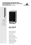
TXA-620CD
Best.-Nr. 17.1290
BEDIENUNGSANLEITUNG
INSTRUCTION MANUAL
MODE D’EMPLOI
ISTRUZIONI PER L’USO
GEBRUIKSAANWIJZING
MANUAL DE INSTRUCCIONES
INSTRUKCJA OBSLUGI
SIKKERHEDSOPLYSNINGER
SÄKERHETSFÖRESKRIFTER
TURVALLISUUDESTA
®
D
Bevor Sie einschalten ...
A
Wir wünschen Ihnen viel Spaß mit Ihrem neuen Gerät
von MONACOR. Dabei soll Ihnen diese Bedienungsanleitung helfen alle Funktionsmöglichkeiten kennen zu
lernen. Die Beachtung der Anleitung vermeidet außerdem Fehlbedienungen und schützt Sie und Ihr Gerät vor
eventuellen Schäden durch unsachgemäßen Gebrauch.
Den deutschen Text finden Sie auf den Seiten 4 – 9.
CH
F
Avant toute mise en service ...
B
Nous vous remercions d’avoir choisi un appareil
MONACOR et vous souhaitons beaucoup de plaisir à
l’utiliser. Cette notice a pour objectif de vous aider à
mieux connaître les multiples facettes de l’appareil et à
vous éviter toute mauvaise manipulation .
CH
GB
We wish you much pleasure with your new unit by
MONACOR. With these operating instructions you will
be able to get to know all functions of the unit. By following these instructions false operations will be avoided,
and possible damage to yourself and your unit due to improper use will be prevented.
You will find the English text on the pages 4 – 9.
I
Voordat u inschakelt ...
B
Wij wensen u veel plezier met uw nieuw toestel van
MONACOR. Met behulp van bijgaande gebruiksaanwijzing zal u alle functiemogelijkheden leren kennen.
Door deze instructies op te volgen zal een slechte werking vermeden worden, en zal een eventueel letsel aan
uzelf en schade aan uw toestel tengevolge van onzorgvuldig gebruik worden voorkomen.
U vindt de nederlandstalige tekst op de pagina’s 16 – 21.
PL
S
Przed Uruchomieniem …
E
Antes de cualquier instalación
Tenemos de agradecerle el haber adquirido un equipo
MONACOR y le deseamos un agradable uso. Este
manual quiere ayudarle a conocer las multiples facetas
de este equipo. La observación de las instrucciones evita
operaciones erróneas y protege Vd. y vuestro aparato
contra todo daño posible por cualquier uso inadecuado.
La versión española se encuentra en las páginas
16 – 21.
DK
Inden De tænder for apparatet ...
Życzymy zadowolenia z nowego produktu MONACOR.
Dzięki tej instrukcji obsługi będą państwo w stanie
poznać wszystkie funkcje tego urządzenia. Stosując się
do instrukcji unikną państwo błędów i ewentualnego
uszkodzenia urządzenia na skutek nieprawidłowego
użytkowania.
Vi ønsker Dem god fornøjelse med Deres nye MONACOR
apparat. Læs oplysningerne for en sikker brug af apparatet før ibrugtagning. Følg sikkerhedsoplysningerne for at
undgå forkert betjening og for at beskytte Dem og Deres
apparat mod skade på grund af forkert brug.
Tekst polski znajduje się na stronach 22 – 24.
Sikkerhedsoplysningerne finder De på side 25.
Förskrift
Vi önskar dig mycket nöje med din nya enhet från
MONACOR. Läs gärna säkerhetsinstruktionerna innan
du använder enheten. Genom att följa säkerhetsinstruktionerna kan många problem undvikas, vilket annars kan
skada enheten.
Du finner säkerhetsinstruktionerna på sidan 25.
2
Prima di accendere ...
Vi auguriamo buon divertimento con il Vostro nuovo apparecchio MONACOR. Le istruzioni per l’uso Vi possono
aiutare a conoscere tutte le possibili funzioni. E
rispettando quanto spiegato nelle istruzioni, evitate di
commettere degli errori, e così proteggete Voi stessi, ma
anche l’apparecchio, da eventuali rischi per uso improprio.
Il testo italiano lo potete trovare alle pagine 10 – 15.
La version française se trouve pages 10 – 15.
NL
Before you switch on ...
FIN
Ennen virran kytkemistä …
Toivomme, että uusi MONACOR-laitteesi tuo sinulle paljon iloa ja hyötyä. Ole hyvä ja lue käyttöohjeet ennen laitteen käyttöönottoa. Luettuasi käyttöohjeet voit käyttää
laitetta turvallisesti ja vältyt laitteen väärinkäytöltä.
Käyttöohjeet löydät sivulta 25.
JACK-LINE
XLR-MIC
VOLUME 1
BASS
TREBLE
VOLUME 3
VOLUME 4
0
0
BASS
TREBLE
1
0
JACK-LINE
XLR-MIC
-5
10
VOLUME 2
-5
+5
BASS
+5
10
R
L
1
-5
-5
+5
2
LIM
PRIORITY MIC 1+2
R
TXA-620CD
INT. CD
(DECK)
+5
3
+5
AMP ON
4
10
-5
+5
MUTE LEVEL
CH 3+4
3
2
0
-5
10
L
TREBLE
4 5
6
0
7
PORTABLE AMPLIFIER
SYSTEM
10
8
9
10
11
➀
22
PROGRAM
STOP/ E J
12
FOLDER
POWER
MP3
CD
13
REPEAT 1
RPT / SHUF
23
24
LEVEL
PLAY / PAUSE
ALL FOLDER SHUFFLE
MEMORY
ENTER
REV
SKIP
25
F.WD
MP3
COMPACT DISC PLAYER
MIN
MAX
26
14
27
ACHTUNG! CAUTION! ATTENTION! ATTENZIONE!
MONACOR® INTERNATIONAL
Vor Öffnen des Gerätes Netzstecker ziehen, Netzleitung
und Netzsicherung nur von Fachpersonal wechseln lassen.
Gerät vor Feuchtigkeit und Hitze schützen. Zulässiger
Einsatztemperaturbereich 0-40 °C. Gerät nur für den
angegebenen Zweck verwenden.
Avant d'ouvrir l'appareil, retirez la fiche secteur d'alimentation.
Toute intervention sur le câble secteur et le fusible secteur
doit être effectuée uniquement par du personnel qualifié.
Protégez l'appareil de l'humidité et de la chaleur. Plage
autorisée de la température d'utilisation 0-40°C. A n'utiliser
que dans le domaine d'application déterminé.
Remove the mains plug before opening the unit. Leave
replacing of the mains supply cord and mains fuse to
qualified service personnel. Protect the unit against moisture
and heat. Permissible operating temperature range 0-40°C.
This product is not intended for use other than stated.
Staccare la spina di rete prima di aprire l'apparecchio, e far
cambiare il cavo di rete ed il fusibile di rete solo da persona
esperta. Proteggere l'apparecchio dall'umidità e dal calore.
Campo della temperatura d'impiego ammessa 0-40 °C.
Usare l'apparecchio solo per lo scopo indicato.
TXA-620CD PORTABLE AMPLIFIER SYSTEM
28
–
FREQUENCY
SERIAL- NO.
863.05 MHz
–
230 V~ /50 Hz /45VA
ACHTUNG! CAUTION! ATTENTION! ATTENZIONE!
F 630 mAL
Gerät in OFF-Stellung nicht vom Netz getrennt! Unit in OFF position not disconnected from the mains! In posizione OFF, I’apparecchio non è separatodalla
rete! En position OFF (arrêt), I’appareil n’est pas coupé du secteur!
+
INPUT
OUTPUT
B
BATTERY
TRANSFER
ON AIR
ON
> 75%
LIM
< 25%
OFF
- CHARGE
RED - CHARGE
GREEN - STANDBY
15
16
a
17
b
h
18
c
MP3
CD
i
1-GROUND
2 PHASE
EXT. SPEAKER
LINE LINK
POWER
ON
3
+
REPEAT 1
j
19
d
e
20
f
21
g
ALL FOLDER SHUFFLE PROGRAM
MEMORY
k
l
ON
POWER AMP
➂
➁
D
A
Bitte klappen Sie die Seite 3 heraus. Sie sehen
dann immer die beschriebenen Bedienelemente
und Anschlüsse.
CH
1
Übersicht der Bedienelemente und
Anschlüsse
1.1 Frontseite
1 Eingangsbuchsen für die Kanäle 1 und 2
(XLR/6,3-mm-Klinken-Kombibuchse):
XLR-Anschluss für ein Mikrofon oder
Klinkenanschluss für ein Audiogerät mit LineAusgang (CD-Spieler, Kassettenrecorder etc.)
2 Lautstärkeregler VOLUME für die Kanäle 1 und 2
Die LED über dem Regler VOLUME 1 leuchtet
bei eingeschaltetem Funkmikrofon.
3 Klangregler BASS und TREBLE jeweils für die
Kanäle 1 und 2
4 Lautstärkeregler VOLUME 3 für den Kanal 3
5 Eingangsbuchsen (Cinch) für Kanal 3 zum Anschluss eines Audiogerätes mit Line-Ausgang
6 Eingangsbuchsen (Cinch) für Kanal 4 zum Anschluss eines Audiogerätes mit Line-Ausgang
Hinweis: Diese Buchsen nur verwenden, wenn
der integrierte CD-Spieler nicht benutzt wird.
7 Lautstärkeregler VOLUME 4 für den Kanal 4
[integrierter CD-Spieler und Cinch-Buchsen (6)]
8 Regler MUTE LEVEL CH 3 + 4 zum Einstellen
der Lautstärkeabsenkung der Kanäle 3 und 4 bei
Mikrofondurchsagen
9 Anzeige-LEDs
PRIORITY MIC 1 + 2, grün
leuchtet, wenn die Lautstärke der Kanäle 3 und
4 automatisch bei einer Mikrofondurchsage
abgesenkt wird
AMP ON, gelb
leuchtet bei eingeschaltetem Gerät
LIM, rot
leuchtet, wenn der integrierte Limiter die Laut-
GB
Please unfold page 3. Then you can always see
the operating elements and connections described.
1
Operating Elements and Connections
1.1 Front panel
1 Input jacks for the channels 1 and 2
(combined XLR/6.3 mm jack):
XLR connection for a microphone or
6.3 mm connection for an audio unit with line output (CD player, tape recorder, etc.)
2 Control VOLUME for the channels 1 and 2
The LED above the control VOLUME 1 lights up
with the wireless microphone switched on.
3 Tone controls BASS and TREBLE, each for the
channels 1 and 2
4 Control VOLUME 3 for channel 3
5 Input jacks (phono) for channel 3 for connection
of an audio unit with line output
6 Input jacks (phono) for channel 4 for connection
of an audio unit with line output
Note: Only use these jacks if the integrated CD
player is not used.
7 Control VOLUME 4 for channel 4
[integrated CD player and phono jacks (6)]
8 Control MUTE LEVEL CH 3 + 4 to adjust the
volume attenuation of channels 3 and 4 in case
of microphone announcements
9 Indicating LEDs
PRIORITY MIC 1 + 2, green
lights up if the volume of channels 3 and 4 is
automatically attenuated in case of a microphone announcement
AMP ON, yellow
lights up with the unit switched on
LIM, red
lights up if the integrated limiter limits the vol-
4
stärke beim Erreichen des maximalen, unverzerrten Pegels begrenzt
10 Klangregler BASS und TREBLE gemeinsam für
die Kanäle 3 und 4
1.2 Rückseite
11 CD-Einzugsschlitz; die CD so weit in den Schlitz
schieben, bis sie automatisch eingezogen wird
12 Taste PROGRAM, um zum Zusammenstellen
einer eigenen Titelfolge in den Programmiermodus zu schalten
13 Ein- /Ausschalter für den CD-Spieler
14 Multifunktionsdisplay (Details siehe Abb. 3)
a Einblendung „CD“ bei Betrieb mit einer AudioCD
b Einblendung „MP3“ bei Betrieb mit einer CD
mit Titeln im MP3-Format
c Einblendungen bei aktivierter Wiederholfunktion – siehe auch Taste RPT/SHUF, Pos. 22
„REPEAT ALL“
Wiederholung aller Titel der CD bzw. einer
programmierten Titelfolge
„REPEAT 1“
Wiederholung des aktuellen Titels
„REPEAT“ (nur bei MP3-CDs)
Wiederholung aller Titel des aktuellen Ordners
d Einblendung „FOLDER“ bei aktiviertem Ordneranwahlmodus – siehe Taste FOLDER,
Pos. 27
e Einblendung „SHUFFLE“ bei Wiedergabe der
Titel in zufallsbedingter Reihenfolge
f Einblendung „PROGRAM“ während des Programmierens einer eigenen Titelfolge
g Einblendung „MEMORY“ beim Abspielen
einer programmierten Titelfolge
h Symbol für den Wiedergabemodus
i Symbol für den Pausenmodus
j nur bei MP3-CDs:
Anzeige der Ordneranzahl auf der CD (im
ume when reaching the maximum, undistorted level
10 Tone controls BASS and TREBLE in common for
channels 3 and 4
1.2 Rear panel
11 CD slot; slide the CD so far into the slot until it is
pulled in automatically
12 Button PROGRAM to switch to the programming
mode to compile an individual title sequence
13 Power switch for the CD player
14 Multifunctional display (details see fig. 3)
a insertion “CD” in case of operation with an
audio CD
b insertion “MP3” in case of operation with a CD
with titles in the MP3 format
c insertions with activated repeat function
– also see button RPT/SHUF, item 22
“REPEAT ALL”
repeat of all titles of the CD or of a programmed title sequence
“REPEAT 1”
repeat of the current title
“REPEAT” (only with MP3 CDs)
repeat of all titles of the current folder
d insertion “FOLDER” with activated folder selecting mode – see button FOLDER, item 27
e insertion “SHUFFLE” in case of replay of the
titles in a random sequence
f insertion “PROGRAM” while programming an
individual title sequence
g insertion “MEMORY” while playing a programmed title sequence
h symbol for the replay mode
i symbol for the pause mode
j only for MP3 CDs:
display of the number of folders on the CD (in
the stop mode) or of the number of the current
folder (in the replay and pause modes)
15
16
17
18
19
20
21
Stopp-Modus) bzw. der Nummer des aktuellen
Ordners (im Wiedergabe- und Pausenmodus)
k Anzeige der Titelanzahl auf der CD (im StoppModus) bzw. der Nummer des aktuellen Titels
(im Wiedergabe- und Pausenmodus)
l Anzeige der bereits gespielten Zeit (Min. : Sek.)
des aktuellen Titels
Halterung für die Netzsicherung;
eine durchgebrannte Sicherung nur durch eine
gleichen Typs ersetzen
Netzbuchse zum Anschluss an eine Steckdose
(230 V~/50 Hz) über das beiliegende Verbindungskabel
Ein-/Ausschalter für das Verstärkerteil
Hinweis: Das Ladeteil ist immer in Betrieb,
sobald das Gerät über die Netzbuchse (16) mit
einer Steckdose verbunden wird.
Ladeanzeige für den internen Akkumulator
> 75 %, grün
leuchtet, wenn der Akku über 75 % geladen ist
< 25 %, rot
leuchtet, wenn die Akkuladung unter 25 %
gefallen ist und der Akku geladen werden sollte
CHARGE, Betriebsanzeige für das Ladeteil
rot: der Akku wird geladen
grün: der Ladevorgang ist beendet
6,3-mm-Klinkenbuchsen LINE LINK INPUT und
OUTPUT zum Betrieb mehrerer Aktivboxen
(siehe Kap. 4.3.3)
6,3-mm-Klinkenbuchse EXT. SPEAKER zum
parallelen Betrieb einer passiven 4-Ω-Lautsprecherbox, z. B. TXB-600
Betriebsanzeigen
TRANSFER ON AIR, grün
ohne Funktion
LIM, rot
leuchtet, wenn der integrierte Limiter die Lautstärke beim Erreichen des maximalen, unverzerrten Pegels begrenzt
POWER AMP ON, gelb
leuchtet bei eingeschaltetem Gerät
k display of the number of titles on the CD (in
the stop mode) or of the number of the current
title (in the replay and pause modes)
l display of the time already played (min. : sec.)
of the current title
15 Support for the mains fuse;
only replace a blown fuse by one of the same type
16 Mains jack for connection to a mains socket
(230 V~/50 Hz) via the supplied connection
cable
17 Power switch for the amplifier part
Note: the charging part is always in operation as
soon as the unit is connected via the mains jack
(16) to a mains socket
18 Charging LEDs for the internal rechargeable battery
> 75 %, green
lights up if the rechargeable battery is charged
more than 75 %
< 25 %, red
lights up if the charge of the rechargeable battery has fallen below 25 % and the rechargable
battery should be charged
CHARGE, power indication for the charging part
red: the rechargeable battery is being charged
green: the charging procedure is terminated
19 6.3 mm jacks LINE LINK INPUT and OUTPUT
for operating several active speaker systems
(see chapter 4.3.3)
20 6.3 mm jack EXT. SPEAKER for parallel operation
of a passive 4 Ω speaker system, e. g. TXB-600
21 Power indications
TRANSFER ON AIR, green
without function
LIM, red
lights up if the integrated limiter limits the volume when reaching the maximum, undistorted
level
POWER AMP ON, yellow
lights up with the unit switched on
22 Taste RPT/SHUF (ENTER), dient:
– zum Anwählen der Wiederholfunktionen und
der Funktion „SHUFFLE“
Grundeinstellung („REPEAT ALL“):
Wiederholung aller Titel der CD bzw. einer
programmierten Titelfolge
erster Tastendruck („SHUFFLE“):
Wiedergabe der Titel in zufallsbedingter
Reihenfolge
nächster Tastendruck:
Funktion „SHUFFLE“ ausgeschaltet, keine
Wiederholfunktion eingeschaltet
nächster Tastendruck („REPEAT 1“):
Wiederholung des aktuellen Titels
nächster Tastendruck („REPEAT“):
Wiederholung aller Titel des aktuellen Ordners (Funktion nur bei MP3-CDs aufrufbar)
nächster Tastendruck:
Zurückschalten auf die Grundeinstellung
– beim Programmieren einer eigenen Titelfolge
zum Bestätigen einer Titelanwahl
23 Taste STOP/EJ:
1. Tastendruck Beenden des Abspielens
2. Tastendruck Auswerfen der CD
24 Taste PLAY/PAUSE zum Umschalten zwischen
Wiedergabe und Pause
25 Pegelregler für den CD-Spieler: den Regler auf
Maximum drehen und die Lautstärke mit dem
Regler VOLUME 4 (7) einstellen
26 SKIP-Tasten für die Titelanwahl, Ordneranwahl
(bei MP3-CDs) und den schnellen Vor- und
Rücklauf innerhalb eines Titels
Titelanwahl
Mit jedem Drücken der Taste F.WD wird ein
Titel vorgesprungen, mit jedem Drücken der
Taste REV ein Titel zurück.
Ordneranwahl (bei MP3-CDs)
Erst die Taste FOLDER (27) drücken [Einblendung „FOLDER“ (d)], dann mit der Vorwärtstaste F.WD oder der Rückwärtstaste REV den
gewünschten Ordner anwählen.
22 Button RPT/SHUF (ENTER), serves:
– to select the repeat functions and the function
“SHUFFLE”
basic setting (“REPEAT ALL”):
repeat of all titles of the CD or of a programmed title sequence
first pressing of button (“SHUFFLE”):
repeat of the titles in a random sequence
next pressing of button:
function “SHUFFLE” switched off, no repeat
function switched on
next pressing of button (“REPEAT 1”):
repeat of the current title
next pressing of button (“REPEAT”):
repeat of all titles of the current folder (function can only be called for MP3 CDs)
next pressing of button:
reset to the basic setting
– while programming an individual title sequence to confirm a title selection
23 Button STOP/EJ:
1st pressing of button to stop the replay
2nd pressing of button to eject the CD
24 Button PLAY/PAUSE for switching between replay and pause
25 Level control for the CD player: turn the control to
maximum and adjust the volume with the control
VOLUME 4 (7)
26 SKIP buttons for the title selection, folder selection (for MP3 CDs) and the fast forward and
reverse within a title
Title selection
Each time the button F.WD is pressed, a title
is advanced, each time the button REV is
pressed, a title is reversed.
Folder selection (for MP3 CDs)
First press the button FOLDER (27) [insertion
“FOLDER” (d)], then select the desired folder
with the forward button F.WD or the reverse
button REV.
1. sichtbare Schäden am Gerät oder an der Netzanschlussleitung vorhanden sind,
2. nach einem Sturz oder Ähnlichem der Verdacht
auf einen Defekt besteht,
3. Funktionsstörungen auftreten.
Geben Sie das Gerät in jedem Fall zur Reparatur
in eine Fachwerkstatt.
schneller Vor-/Rücklauf
Für den Vorlauf die Taste F.WD gedrückt halten, für den Rücklauf die Taste REV.
27 Taste FOLDER für die Anwahl von Ordnern (Dateienverzeichnissen) auf MP3-CDs:
Zum Aktivieren des Ordneranwahlmodus die
Taste FOLDER drücken [Einblendung „FOLDER“ (d)], dann den Ordner mit einer der SKIPTasten (26) anwählen. Zum Deaktivieren des
Ordneranwahlmodus die Taste FOLDER erneut
drücken.
●
Ziehen Sie den Netzstecker nie an der Zuleitung
aus der Steckdose, fassen Sie immer am Stecker
an!
●
Verwenden Sie zum Reinigen nur ein trockenes
weiches Tuch, niemals Chemikalien oder Wasser.
●
Dieses Gerät entspricht der Richtlinie für elektromagnetische Verträglichkeit 89/336/EWG und der
Niederspannungsrichtlinie 73/23/EWG.
Wird das Gerät zweckentfremdet, nicht richtig
angeschlossen, falsch bedient oder nicht fachgerecht repariert, kann keine Garantie für das Gerät
und keine Haftung für daraus resultierende Sachoder Personenschäden übernommen werden.
●
Achtung! Das Gerät wird mit lebensgefährlicher
Netzspannung (230 V~) versorgt. Nehmen Sie deshalb nie selbst Eingriffe im
Gerät vor. Durch unsachgemäßes Vorgehen besteht die Gefahr eines elektrischen Schlages. Außerdem erlischt
beim Öffnen des Gerätes jeglicher
Garantieanspruch.
Soll das Gerät endgültig aus dem Betrieb genommen werden, übergeben Sie es zur umweltgerechten Entsorgung einem örtlichen Recyclingbetrieb.
3
Einsatzmöglichkeiten und Zubehör
28 Lüftungsschlitze; nicht abdecken, damit es im
Gerät nicht zu einer Überhitzung kommt!
2
Hinweise für den sicheren Gebrauch
Beachten Sie auch unbedingt die folgenden Punkte:
●
Verwenden Sie das Gerät nur im Innenbereich.
Schützen Sie es vor Tropf- und Spritzwasser,
hoher Luftfeuchtigkeit und Hitze (zulässiger Einsatztemperaturbereich 0 – 40 °C).
●
Stellen Sie keine mit Flüssigkeit gefüllten Gefäße,
z. B. Trinkgläser, auf das Gerät.
●
Die im Gerät entstehende Wärme muss durch
Luftzirkulation abgegeben werden. Decken Sie
die Lüftungsöffnungen (28) nicht ab.
●
Nehmen Sie das Gerät nicht in Betrieb bzw. ziehen Sie sofort den Netzstecker aus der Steckdose, wenn:
Fast forward/reverse
For the fast forward keep the button F.WD
pressed, for the reverse the button REV.
27 Button FOLDER for the selection of folders (file
directories) on MP3 CDs:
To activate the folder selecting mode, press the
button FOLDER [insertion “FOLDER” (d)], then
select the folder with one of the SKIP buttons
(26). To deactivate the folder selecting mode,
press the button FOLDER again.
28 Ventilation slots; do not cover them to prevent
overheating inside the unit!
2
Attention! The unit is supplied with hazardous
mains voltage (230 V~). Leave servicing to skilled personnel only. Inexpert
handling may cause an electric shock
hazard. Furthermore, any guarantee
claim will expire if the unit has been
opened.
It is essential to observe the following items:
● The unit is suitable for indoor use only. Protect it
against dripping water and splash water, high air
humidity, and heat (admissible ambient temperature range 0 – 40 °C).
● Do not place any vessels filled with liquid, e. g.
drinking glasses, on the unit.
● The heat being generated in the unit has to be
removed via air circulation. Therefore, the air
vents (28) must not be covered.
● Do not set the unit into operation, and immediately
disconnect the mains plug from the mains socket
if
1. there is visible damage to the unit or to the
mains cable,
CH
Der TXA-620CD ist eine Kombination aus Lautsprecherbox, Verstärker mit vier Eingangskanälen, Empfangsteil für ein Funkmikrofon (Übertragungsfrequnz 863,05 MHz) und CD-Spieler. Das Gerät ist
speziell für einen netzunabhängigen Betrieb ausgelegt. Zur Stromversorgung ist ein Akkumulator integriert, der mit dem internen Ladeteil aufgeladen werden kann. Dadurch eignet sich das Gerät ideal für
den mobilen Einsatz zur Beschallung bei Veranstaltungen, Vorträgen etc.
Über die Durchschleifanschlüsse lässt sich der
TXA-620CD mit weiteren Aktivboxen (z. B. TXA-600
von MONACOR) zusammenschalten, um einen
größeren Bereich beschallen zu können. Es kann
aber auch eine passive 4-Ω-Lautsprecherbox parallel betrieben werden (z. B. das im Design passende
Modell TXB-600). Die Eingangskanäle lassen sich
folgendermaßen nutzen:
2. a defect might have occurred after a drop or
similar accident,
3. there are malfunctions.
The unit must in any case be repaired by skilled
personnel.
●
Never pull the mains cable to disconnect the
mains plug from the mains socket, always seize
the plug!
●
For cleaning only use a dry, soft cloth, by no
means chemicals or water.
●
No guarantee claims for the unit and no liability for
any resulting personal damage or material damage will be accepted if the unit is used for other
purposes than originally intended, if it is not correctly connected or operated, or not repaired in an
expert way.
●
If the unit is to be put out of operation definitively,
take it to a local recycling plant for a disposal
which is not harmful to the environment.
●
Important for U. K. Customers!
The wires in the mains lead of the power supply unit
are coloured in accordance with the following code:
green/yellow = earth
blue = neutral
brown = live
Safety Notes
This unit corresponds to the directive 89/336/EEC
for electromagnetic compatibility and to the low voltage directive 73/23/EEC.
D
A
GB
As the colours of the wires in the mains lead of this
appliance may not correspond with the coloured
markings identifying the terminals in your plug,
proceed as follows:
1. The wire which is coloured green and yellow
must be connected to the terminal in the plug
which is marked with the letter E or by the earth
symbol , or coloured green or green and yellow.
2. The wire which is coloured blue must be connected to the terminal which is marked with the
letter N or coloured black.
3. The wire which is coloured brown must be connected to the terminal which is marked with the
letter L or coloured red.
Warning - This appliance must be earthed.
5
D
A
CH
Kanal 1 für ein Funkmikrofon oder
für ein kabelgebundenes Mikrofon oder
für ein Audiogerät mit Line-Ausgang (z. B.
CD-Spieler, Kassettenrecorder)
Kanal 2 für ein kabelgebundenes Mikrofon oder
für ein Audiogerät mit Line-Ausgang
Kanal 3 für ein Audiogerät mit Line-Ausgang
Kanal 4 für den integrierten CD-Spieler oder ein
Audiogerät mit Line-Ausgang
Aus dem Sortiment von MONACOR können z. B.
folgende Funkmikrofone mit dem TXA-620CD verwendet werden:
Typ
Bezeichnung
Bestell-Nr.
Handmikrofon mit
integriertem Sender
TXS-820HT
24.0900
4.1 Aufstellung des Gerätes
Der TXA-620CD kann frei aufgestellt oder über die
Stativhülse auf der Geräteunterseite auf ein PABoxen-Stativ (z. B. PAST-Serie aus dem Sortiment
von MONACOR) gesteckt werden.
Für den Betrieb muss das Gerät nicht aus der
mitgelieferten Transporttasche herausgenommen
werden. Jedoch dürfen die Lüftungsöffnungen (28)
nicht verdeckt sein. Durch Öffnen der Reißverschlüsse sind alle Anschlüsse und Bedienelemente
zugänglich. Die so gelösten Taschenteile können
hochgeklappt und am Klettverschluss fixiert werden.
4.2 Stromversorgung
Die Zulassung für das Gerät ist nach der R + TTERichtlinie (Radio and Telecommunication Technical
Equipment) in den Staaten der Europäischen Union
gültig. Die Zulassungsnummer ist in den technischen Daten angegeben. Für den Betrieb in Staaten
außerhalb der EU fragen Sie bitte Ihren Fachhändler oder die MONACOR-Niederlassung des entsprechenden Landes.
In der Bundesrepublik Deutschland ist die Frequenz 863,05 MHz für den Betrieb von drahtlosen
Audio-Übertragungssystemen freigegeben. Da diese
Frequenz in anderen Ländern der EU für diesen Anwendungszweck möglicherweise nicht zur Verfügung steht, informieren Sie sich bei Betrieb des
Gerätes außerhalb Deutschlands bitte bei Ihrem
Fachhändler oder bei der entsprechenden Behörde
des Landes.
3
3.1 Approval
TXS-820HSE
24.0880
Taschensender mit
Krawattenmikrofon
TXS-820LT
24.0920
Taschensender mit
Kopfbügelmikrofon
TXS-820SX
24.0940
3.1 Zulassung
Applications and Accessories
The TXA-620CD is a combination of a speaker
system, an amplifier with four input channels, a
receiver part for a wireless microphone (transmission frequency 863.05 MHz), and a CD player. The
unit is especially designed for an operation independent of the mains. For the power supply, a
rechargeable battery is integrated which can be
charged with the internal charging part. Thus, the
unit is ideally suited for mobile PA applications in
case of events, lectures, etc.
The feed-through terminals allow interconnection
of the TXA-620CD with other active speaker systems
(e. g. MONACOR TXA-600) for PA application in
large areas. But it is also possible to operate in parallel a passive 4 Ω speaker system (e. g. model
TXB-600 of matching design). The input channels
can be used as follows:
Channel 1 for a wireless microphone or
for a cable-connected microphone or
for an audio unit with line output
(e. g. CD player, tape recorder)
Channel 2 for a cable-connected microphone or
for an audio unit with line output
Channel 3 for an audio unit with line output
Channel 4 for the integrated CD player or an audio
unit with line output
From the product range of MONACOR e. g. the following wireless microphones can be used with the
TXA-620CD:
Type
Hand-held microphone with
integrated transmitter
Pocket transmitter for a headband
microphone, e. g. HSE-110
6
Inbetriebnahme
Die Stromversorgung erfolgt über den integrierten
Akkumulator, der mit dem internen Ladeteil aufgeladen werden kann.
1) Zum Aufladen das beiliegende Netzkabel zuerst
in die Netzbuchse (16) stecken und dann den
Netzstecker in eine Steckdose (230 V~/50 Hz).
2) Die Ladekontrolle CHARGE (18) leuchtet:
rot = der Akku wird geladen
grün = der Ladevorgang ist beendet
Während des Ladens kann das Gerät betrieben
werden, jedoch steht nicht die volle Leistung zur
Verfügung, solange die rote LED „< 25 %“ (18)
leuchtet. Der Ladevorgang verkürzt sich, wenn
das Gerät mit dem Schalter POWER (17) ausgeschaltet ist.
3) Ist der Akku voll geladen, leuchtet die Ladekontrolle CHARGE grün. Bei maximaler Lautstärke
ist dann eine netzunabhängige Betriebsdauer
von bis zu 8 Stunden möglich. Bei einer geringeren Lautstärke verlängert sich die Betriebsdauer.
4) Der Akku sollte wieder geladen werden, wenn die
rote LED „< 25 %“ aufleuchtet.
5) Durch die Ladeautomatik kann der Akku nicht
überladen werden. Jedoch sollte der Netzstecker
aus der Steckdose gezogen werden, wenn der
Taschensender für ein
Kopfbügelmikro z. B. HSE-110
GB
4
Designation
Order No.
TXS-820HT
24.0900
TXS-820HSE
24.0880
Pocket transmitter with
tie-clip microphone
TXS-820LT
24.0920
Pocket transmitter with
headband microphone
TXS-820SX
24.0940
According to the R + TTE regulation (Radio and Telecommunication Technical Equipment) the approval of
the unit is valid in the countries of the European Union.
The approval number is indicated in the specifications.
For the operation in countries outside the EU, please
contact your retailer or the MONACOR subsidiary in
the country where this system will be operated.
In the Federal Republic of Germany, the frequency of 863.05 MHz has been approved for the
operation of wireless audio transmission systems. As
it is possible that this frequency is not available for
this field of application in other countries of the EU,
please contact your retailer or the corresponding authorities of the particular country when this system is
operated outside the Federal Republic of Germany.
4
Setting into Operation
4.1 Setting up the unit
The TXA-620CD can be placed as desired or be
mounted to a PA speaker cabinet stand via the stand
sleeve on the lower side of the unit (e. g. PAST
series of the MONACOR product range).
For operation, it is not necessary to remove the
unit from the supplied transport bag. However, the
ventilation slots (28) must not be covered. By opening the zip-fasteners all connections and operating
elements are accessible. The parts of the bag
opened up can now be folded upwards and fixed at
the velcro fastener.
4.2 Power supply
The power supply is made via the integrated rechargeable battery which is charged with the internal charging part.
1) For charging, first connect the supplied mains
cable to the mains jack (16) and then connect the
mains plug to a mains socket (230 V~/50 Hz).
2) The LED CHARGE (18) lights up:
red = the rechargeable battery is being charged
green = the charging procedure is terminated
Akku voll geladen ist (Anzeige CHARGE leuchtet
grün) und das Gerät längere Zeit nicht benötigt
wird. Anderenfalls wird auch bei ausgeschaltetem Gerät stets ein geringer Strom verbraucht.
4.3 Anschlüsse herstellen
4.3.1 Mikrofone
Wird ein Funkmikrofon verwendet, ist der Kanal 1
hiermit belegt. Zusätzlich kann ein kabelgebundenes Mikrofon über einen XLR-Stecker an die Buchse
XLR-MIC 2 (1) angeschlossen werden. Wird kein
Funkmikrofon eingesetzt, lässt sich auch an den
Kanal 1 ein kabelgebundenes Mikrofon anschließen.
4.3.2 Audiogeräte
Bis zu vier Audiogeräte mit Line-Ausgang, z. B. CDSpieler, Kassettenrecorder, lassen sich an den TXA620CD anschließen. Vorrangig sollten dafür die
Kanäle 3 und 4 verwendet werden, weil diese automatisch bei einer Mikrofondurchsage in der Lautstärke abgesenkt werden können.
Anschluss:
Kanal 1 über die 6,3-mm-Klinkenbuchse JACKLINE 1 (1), wenn kein Funkmikrofon diesen Kanal belegt
Kanal 2 über die 6,3-mm-Klinkenbuchse JACKLINE 2 (1)
Kanal 3 über die Cinch-Buchsen (5)
Kanal 4 über die Cinch-Buchsen (6), wenn der
integrierte CD-Spieler nicht benutzt wird
4.3.3 Mehrere Aktivboxen parallel betreiben
Werden mehrere Aktivboxen (z. B. TXA-600 von
MONACOR) zur Beschallung benötigt, diese über
die Buchsen LINE LINK (19) verbinden:
1) Die Buchse OUTPUT des Hauptgerätes, an dem
alle Audiogeräte und Mikrofone angeschlossen
sind, über ein Audiokabel mit 6,3-mm-Klinkensteckern an die Buchse INPUT des zweiten Gerätes
anschließen.
During the charging the unit can be operated,
however, the full power is not available as long as
the red LED “< 25 %” (18) lights up. The charging
procedure is shortened if the unit is switched off
with the POWER switch (17).
3) If the rechargeable battery is fully charged, the
charging control CHARGE shows green. At maximum volume an operating time independent of
the mains of up to 8 hours is possible. With a
lower volume, the operating time is extended.
4) The rechargeable battery should be charged
again if the red LED “< 25 %” lights up.
5) Due to the automatic charging, the rechargeable
battery cannot be overcharged. However, the
mains plug should be disconnected if the rechargeable battery is fully charged (indication
CHARGE shows green) and the unit is not used
for a longer time. Otherwise, even with the unit
switched off, a low current will always be consumed.
4.3 Making the connections
4.3.1 Microphones
If a wireless microphone is used, channel 1 is reserved by this. In addition a cable-connected microphone may be connected via an XLR plug to the jack
XLR-MIC 2 (1). If no wireless microphone is used, it
is also possible to connect a cable-connected microphone to channel 1.
4.3.2 Audio units
Up to four audio units with line output, e. g. CD
player, tape recorder, can be connected to the
TXA-620CD. Channels 3 and 4 should be used as a
priority because their volume can automatically be
attenuated in case of a microphone announcement.
Connection:
Channel 1 via the 6.3 mm jack JACK-LINE (1) if no
wireless microphone reserves this channel
Channel 2 via the 6.3 mm jack JACK-LINE 2 (1)
2) Die Buchse OUTPUT des zweiten Gerätes mit
der Buchse INPUT des dritten Gerätes verbinden
usw.
3) An den zusätzlichen Geräten stets alle Regler
VOLUME (2, 4, 7) auf „0“ stellen, weil die Lautstärke und der Klang nur über das Hauptgerät
eingestellt werden.
5) Den Klang für die Kanäle 1 und 2 getrennt mit den
Reglern BASS und TREBLE (3) optimal einstellen
sowie den Klang für die Kanäle 3 und 4 gemeinsam mit den Reglern BASS und TREBLE (10).
4.3.4 Passive Lautsprecherbox
Wird zur Beschallung zusätzlich eine Lautsprecherbox (ohne Verstärker) benötigt, kann diese an die
Buchse EXT. SPEAKER (20) angeschlossen werden. Die Impedanz der Lautsprecherbox muss
mindestens 4 Ω betragen. Die Lautsprecherbox
TXB-600, dessen Design dem des TXA-620CD entspricht, ist speziell für diesen Zweck vorgesehen.
6) Erfolgt über Kanal 1 oder 2 eine Mikrofondurchsage, kann dabei die Lautstärke für die Kanäle 3
und 4 automatisch reduziert werden. Dazu die
Stärke der Reduzierung mit dem Regler MUTE
LEVEL CH 3 + 4 (8) einstellen. In der Position „0“
erfolgt keine Lautstärkeabsenkung. Wenn das
Gerät bei einer Durchsage die Lautstärke der
Kanäle 3 und 4 verringert, leuchtet die grüne LED
PRIORITY MIC 1 + 2 (9) auf.
5
7) Nach dem Betrieb das Gerät mit dem Schalter
POWER ausschalten und bei Verwendung eines
Funkmikrofons nicht vergessen, auch dieses
auszuschalten, sonst sind bei dem nächsten
Betrieb dessen Batterien verbraucht.
Bedienung
5.1 Verstärker
1) Vor dem Einschalten alle Regler VOLUME (2, 4,
7) auf „0“ drehen, um Einschaltgeräusche zu vermeiden.
2) Mit dem Schalter POWER (17) das Gerät einschalten. Die gelben LEDs AMP ON (9, 21)
leuchten. Das Verstärkerteil und das Empfangsteil sind in Betrieb.
3) Wird ein Funkmikrofon verwendet, dieses einschalten. Die rote LED über dem Regler
VOLUME 1 (1) leuchtet. Wenn nicht, die Batterie
des Mikrofons überprüfen oder den Abstand zwischen Gerät und Mikrofon verringern. Die Reichweite beträgt ca. 30 m.
4) Alle angeschlossenen Geräte einschalten und
deren Signale mit den entsprechenden Reglern
VOLUME (2, 4, 7) am TXA-620CD mischen oder
nach Bedarf ein- und ausblenden. Die Regler der
nicht benutzten Kanäle stets auf „0“ stellen.
Die roten LEDs LIM (9, 21) leuchten, wenn
der integrierte Limiter die Lautstärke beim Erreichen des maximalen, unverzerrten Pegels be-
Channel 3 via the phono jacks (5)
Channel 4 via the phono jacks (6) if the integrated
CD player is not used
4.3.3 Parallel operation of several active speaker
systems
If several active speaker systems (e. g. MONACOR
TXA-600) are required for PA application, connect
them via the jacks LINE LINK (19).
1) Connect the jack OUTPUT of the main unit to
which all audio units and microphones are connected via an audio cable with 6.3 mm plug to the
jack INPUT of the second unit.
2) Connect the jack OUTPUT of the second unit to
the jack INPUT of the third unit etc.
3) Always set all controls VOLUME (2, 4, 7) of the
additional units to “0” because the volume and
the sound are only set via the main unit.
grenzt. Sollten die LEDs ständig leuchten, die
Lautstärke der entsprechenden Kanäle mit den
Reglern VOLUME verringern.
5.2 CD-Spieler
Es können Audio-CDs, selbst gebrannte Audio-CDs
(Audio CD-R) sowie CDs mit Titeln im MP3-Format
abgespielt werden.
Der CD-Spieler ist mit einem Anti-Schock-Speicher ausgestattet, in den vor der Wiedergabe die
Musik eingelesen wird. Bei einer Störung der CDAbtastung durch Stöße oder Vibration wird die
Musik aus dem Speicher gelesen. So werden Tonunterbrechungen umgangen. Das Anti-Schock-System kann jedoch keine anhaltenden, heftigen Stöße
oder Vibrationen ausgleichen. Aus diesem Grund
muss der CD-Spieler immer stationär betrieben werden, d. h. der TXA-620CD muss bei CD-Betrieb auf
standfestem, unbeweglichem Untergrund stehen
und darf keinen starken Erschütterungen ausgesetzt sein.
Der CD-Spieler belegt den Kanal 4, d. h. an den
Cinch-Buchsen (6) darf während der CD-Wiedergabe kein Signal anliegen.
4)
5)
6)
4.3.4 Passive speaker system
If a speaker system (without amplifier) is additionally
required for PA applications, it may be connected to
the jack EXT. SPEAKER (20). The impedance of the
speaker system must at least be 4 Ω. The speaker
system TXB-600, the design of which corresponds
to that of the TXA-620CD, has especially been provided for this purpose.
7)
5
Operation
reduce the distance between unit and microphone. The range is approx. 30 m.
Switch on all connected units and mix their signals with the corresponding controls VOLUME
(2, 4, 7) on the TXA-620CD or fade them in or out
as required. Always set the controls of the channels not used to “0”.
The red LEDs LIM (9, 21) light up if the integrated limiter limits the volume when reaching
the maximum, undistorted level. If the LEDs
should light up permanently, reduce the volume
of the corresponding channels with the controls
VOLUME.
Adjust the sound for the channels 1 and 2 with
the controls BASS and TREBLE (3) separately in
an optimum way and the sound for the channels
3 and 4 in common with the controls BASS and
TREBLE (10).
If a microphone announcement is made via channel 1 or channel 2, the volume for the channels 3
and 4 can automatically be reduced. For this purpose adjust the extent of the reduction with the
control MUTE LEVEL CH 3 + 4 (8). In position “0”
there is no volume attenuation. If the unit reduces
the volume of channels 3 and 4 during an announcement, the green LED PRIORITY MIC
1 + 2 (9) lights up.
After the operation switch off the unit with the
POWER switch. When using the wireless microphone, remember to switch it off as well otherwise the batteries will be exhausted the next time
the microphone is used.
5.1 Amplifier
1) Prior to switching on, set all controls VOLUME (2,
4, 7) to “0” to prevent switching-on noise.
2) Switch on the unit with the POWER switch (17).
The yellow LEDs AMP ON (9, 21) light up. The
amplifier part and the receiving part are in operation.
3) If a wireless microphone is used, switch it on. The
red LED above the control VOLUME 1 (1) lights
up. If not, check the battery of the microphone or
5.2 CD player
It is possible to play audio CDs, audio CDs you have
burnt yourself (audio CD-R), and CDs with titles in
the MP3 format.
The CD player is equipped with an anti-shock
memory in which the music is read in prior to the
replay. In case of an interference of the CD sampling
by shocks or vibrations the music is read from the
memory. Thus, sound interruptions are prevented.
5.2.1 CD abspielen
1) Zum Einschalten des CD-Spielers den Ein-/Ausschalter POWER (13) betätigen. Auf dem Display
(14) erscheinen nacheinander folgende Anzeigen:
(laden)
(öffnen)
(keine CD) – wenn keine CD eingelegt ist
2) Eine CD mit der Beschriftung nach oben so weit
in den Einzugsschlitz (11) schieben, bis sie automatisch eingezogen wird. Im Display erscheint
(schließen), gefolgt von
, danach wird
entweder „CD“ (a) bei Audio-CDs oder „MP3“ (b)
bei CDs mit Titeln im MP3-Format eingeblendet.
3) Nach dem Einlesen der CD zeigt das Display
kurz die Gesamtanzahl aller Titel (k) und bei
MP3-CDs zusätzlich die Gesamtanzahl aller Ordner (j), in denen sich die MP3-Dateien befinden
(siehe den Hinweis unten und den Hinweis in
Kap. 5.2.3).
Danach wird der erste Titel (k) angezeigt bzw.
bei MP3-CDs der erste Titel (k) des ersten Ordners (j). Soll mit einem anderen als dem ersten
Titel gestartet werden, diesen anwählen, solange
die Zeitangabe (l) für den ersten Titel „- - : - -“
anzeigt, siehe dazu Kap. 5.2.2 bzw. 5.2.3.
Hinweis: Wenn die MP3-CD keine Ordnerstruktur aufweist, fasst der CD-Spieler alle
Titel der CD in einem Ordner (Ordner 1)
zusammen.
4) Die Wiedergabe startet. Während des Abspielens ist das Wiedergabesymbol (h) eingeblendet
und die Zeitangabe (l) zeigt die bereits verstrichene Abspielzeit des Titels an (Min. : Sek.).
5) Den Regler LEVEL (25) auf Maximum drehen und
die gewünschte Lautstärke mit dem Regler
VOLUME 4 (7) einstellen.
6) Mit der Taste PLAY/PAUSE (24) kann zwischen
Wiedergabe und Pause gewechselt werden. Im
Pausenmodus ist das Pausensymbol (i) eingeblendet und die Zeitangabe (l) blinkt.
7) Nach dem Einschalten ist als Grundeinstellung
die Funktion „Wiederholung aller Titel“ aktiviert
However, the anti-shock system cannot equalize
continuous, heavy shocks or vibrations. For this reason the CD player must always be operated in a stationary way, i.e. the TXA-620CD must stand on a
steady, immobile ground and must not be exposed to
heavy shocks.
The CD player reserves channel 4, i.e. during
reproduction of the CD, no signal must be applied to
the phono jacks (6).
D
A
CH
GB
5.2.1 Playing a CD
1) To switch on the CD player, actuate the on/off
switch POWER (13). The following messages are
successively shown on the display (14):
– if no CD has been inserted
2) Slide a CD with the lettering facing upwards so
far into the slot (11) until it is automatically pulled
in. The display shows
, followed by
,
then either “CD” (a) for audio CDs or “MP3” (b)
for CDs with titles in the MP3 format is inserted.
3) After reading in the CD, the display shortly shows
the total number of all titles (k) and for MP3 CDs
in addition the total number of all folders (j) containing the MP3 files (see the note below and the
note in chapter 5.2.3).
Then the first title (k) is shown or for MP3 CDs
the first title (k) of the first folder (j). To start with
another title than the first, select this title as long
as the time indication (l) for the first title shows
“- - : - -”, see chapter 5.2.2 or 5.2.3.
Note: If the MP3 CD does not show a folder
structure, the CD player comprises all titles of the CD in one folder (folder 1).
4) The replay starts. While replaying, the replay
symbol (h) is inserted and the time indication (l)
shows the playing time of the title already
elapsed (min. : sec.).
5) Turn the control LEVEL (25) to maximum and
adjust the desired volume with the control
VOLUME 4 (7).
7
D
A
CH
(siehe dazu Kap. 5.2.6), d. h. die CD wird endlos
wiederholt. Soll das Abspielen vorzeitig beendet
werden, die Taste STOP/EJ (23) drücken. Der
CD-Spieler schaltet dann in den Stopp-Modus.
8) Zum Auswerfen der CD im Stopp-Modus die Taste
STOP/EJ drücken. Das Display zeigt
, die
CD wird herausgefahren und kann entnommen
werden. Sie kann aber auch durch erneutes
Drücken der Taste STOP/EJ wieder eingefahren
werden.
Wird die CD nicht aus dem Einzugsschlitz entnommen, zieht der CD-Spieler sie nach ca. 15 s
wieder automatisch ein.
5.2.2 Titelanwahl
Zur Titelanwahl die jeweilige SKIP-Taste (26) drücken (nicht im Pausenmodus möglich):
Mit jedem Drücken der Taste F.WD wird ein Titel
vorgesprungen.
Mit jedem Drücken der Taste REV wird ein Titel
zurückgesprungen.
Nach der Anwahl des Titels startet seine Wiedergabe.
5.2.3 Ordneranwahl bei MP3-CDs
Bei MP3-CDs mit mehreren Ordnern (Dateienverzeichnissen) kann jeder Ordner direkt angewählt
werden (nicht im Pausenmodus):
1) Die Taste FOLDER (27) drücken. Zur Anzeige,
dass der Ordneranwahlmodus aktiviert ist, erscheint im Display die Einblendung „FOLDER“ (d).
2) Den gewünschten Ordner mit den SKIP-Tasten
(26) anwählen: Mit jedem Drücken der Taste
F.WD wird ein Ordner weitergesprungen. Mit
jedem Drücken der Taste REV wird ein Ordner
zurückgesprungen.
Hinweis: Die Durchnummerierung und damit die
Reihenfolge der Ordner entspricht der
Ordnerstruktur auf der CD: erst alle
Ordner der Hauptebene, dann alle Ordner der 2. Ebene, dann alle Ordner der
3. Ebene usw. Titel auf der Haupte-
GB
6) With the button PLAY/PAUSE (24) it is possible
to change between replay and pause. In the
pause mode, the pause symbol (i) is inserted and
the time display (l) flashes.
7) After switching on, the function “Repeat of all titles” is activated as a basic setting (see chapter
5.2.6), i. e. the CD is repeated continuously. To
stop the replay before the end, press the button
STOP/EJ (23). Then the CD player switches to
the stop mode.
8) To eject the CD in the stop mode, press the button STOP/EJ. The display shows
, the CD is
ejected and can be removed. However, it is also
possible to retract the CD by pressing the button
STOP/EJ again.
If the CD is not removed from the slot, it is
automatically retracted by the CD player after
approx. 15 s.
5.2.2 Title selection
Press the respective SKIP button (26) for title selection (not possible in the pause mode):
Each time the button F.WD is pressed, a title is
advanced.
Each time the button REV is pressed, a title is reversed.
After selection of the title, the replay of this title
starts.
5.2.3 Folder selection for MP3 CDs
For MP3 CDs with several folders (file directories)
each folder can directly be selected (not in the
pause mode):
1) Press the button FOLDER (27). To indicate that
the folder selecting mode has been activated, the
display shows the insertion “FOLDER” (d).
2) Select the desired folder with the SKIP buttons
(26): Each time the button F.WD is pressed, the
unit advances one folder. Each time the button
REV is pressed, the unit reverses one folder.
Note: The numbering and thus the order of the
folders corresponds to the folder structure
8
bene, die keinem Ordner zugeordnet
sind, werden vom CD-Spieler immer zu
Ordner Nr. 1 zusammengefasst und
allen Ordnern vorangestellt.
6) Mit den SKIP-Tasten (26) kann jeder Titel der Titelfolge angewählt werden oder, durch Gedrückthalten der jeweiligen SKIP-Taste, der schnelle Vor-/
Rücklauf innerhalb eines Titels aktiviert werden.
3) Nach der Ordneranwahl startet die Wiedergabe
mit dem ersten Titel des Ordners. Zum Anwählen
eines anderen Titels zuerst den Ordneranwahlmodus durch Drücken der Taste FOLDER (27)
wieder ausschalten [Einblendung „FOLDER“ (d)
erlischt] und den Titel mit einer der SKIP-Tasten
anwählen.
7) Nach dem Abspielen der Titelfolge oder bei einmaligem Drücken der Taste STOP/EJ (23) schaltet der CD-Spieler auf Stopp. Mit der Taste PLAY/
PAUSE (24) kann das Abspielen der Titelfolge
neu gestartet werden.
5.2.4 Schneller Vor-/Rücklauf
Während des Abspielens kann mit den SKIP-Tasten
(26) innerhalb eines Titels schnell vor- oder zurückgefahren werden: Für den schnellen Vorlauf die
Taste F.WD gedrückt halten, für den schnellen
Rücklauf die Taste REV gedrückt halten.
Hinweis: Solange die Taste gedrückt gehalten wird,
läuft die Wiedergabe in normaler Geschwindigkeit weiter, erst nach dem Lösen
der Taste startet die Wiedergabe ab der
mit dem Vor-/Rücklauf erreichten Stelle.
5.2.5 Eigene Titelfolge zusammenstellen
1) Um in den Programmiermodus zu schalten, die
Taste PROGRAM (12) drücken. Im Display erscheinen die Einblendung „PROGRAM“ (f), die
Titelnummer (k) des ersten Titels bzw. bei MP3CDs die Titelnummer (k) des ersten Titels im ersten
Ordner (j) sowie die Speicherplatznummer 1 (l).
2) Den ersten Titel für die gewünschte Titelfolge anwählen – siehe dazu Kap. 5.2.2 oder 5.2.3.
3) Zur Bestätigung der Titelanwahl die Taste ENTER
(22) drücken. Das Display zeigt die Speicherplatznummer 2 (l).
4) Die Bedienschritte 2 und 3 für alle weiteren gewünschten Titel wiederholen, bis die gesamte
Titelfolge programmiert ist.
5) Zum Starten der Titelfolge die Taste PLAY/
PAUSE (24) drücken: Im Display erscheint
„MEMORY“ (g) und die Titelfolge wird abgespielt.
on the CD: First all folders of the main
level, then all folders of the second level,
then all folders of the third level, etc. Titles
on the main level which are not assigned
to a folder are always combined in folder
No. 1 by the CD player and placed ahead
of all folders.
3) After the folder selection, the replay starts with
the first title of the folder. To select another title,
first press the button FOLDER (27) to switch off
the folder selecting mode again [insertion “FOLDER“ (d) is extinguished] and select the title with
one of the SKIP buttons.
5.2.4 Fast forward/reverse
While replaying, fast forward or reverse within a title
is possible with the SKIP buttons (26): For the fast
forward keep the button F.WD pressed, for the fast
reverse keep the button REV pressed.
Note: As long as the button is kept pressed, the
replay runs at standard speed, only after
releasing the button, the replay starts from the
spot reached with forward/reverse.
5.2.5 Compiling an individual title sequence
1) To switch to the programming mode, press the
button PROGRAM (12). The display shows the
insertion “PROGRAM” (f), the title number (k) of
the first title or for MP3 CDs the title number (k) of
the first title in the first folder (j) and the memory
space number 1 (l).
2) Select the first title for the desired title sequence
– see chapter 5.2.2 or 5.2.3.
3) To confirm the title selection, press the button
ENTER (22). The display shows the memory
space number 2 (l).
4) Repeat the operating steps 2 and 3 for all further
desired titles until the entire title sequence has
been programmed.
5) To start the title sequence, press the button PLAY/
PAUSE (24): The display shows “MEMORY” (g)
and the title sequence is replayed.
8) Mit der Taste RPT/SHUF (22) lassen sich folgende Wiederholfunktionen einschalten (siehe dazu
Kap. 5.2.6):
1. Tastendruck: „REPEAT 1“
2. Tastendruck: „REPEAT ALL“
3. Tastendruck: Wiederholung wieder ausgeschaltet
9) Um wieder in den normalen Betriebsmodus
(Abspielen der CD) zurückzukehren, die Taste
PROGRAM (12) drücken. Im Display erlischt
„MEMORY“ (g). Die Titelfolge ist dann gelöscht.
(Auch das Auswerfen der CD führt zu einem
Löschen der Titelfolge.)
5.2.6 Wiederholfunktionen/Funktion „SHUFFLE”
Nach dem Einschalten ist immer „Wiederholung
aller Titel“ aktiviert, d. h. endloses Abspielen der gesamten CD bzw. einer selbst programmierten Titelfolge [Einblendung „REPEAT ALL“].
Durch mehrmaliges Drücken der Taste RPT/
SHUF (22) lassen sich andere Wiederholfunktionen
sowie die Funktion „SHUFFLE“ anwählen. Die gewählte Funktion wird im Display durch die entsprechende „REPEAT“-Einblendung (c) bzw. die Einblendung „SHUFFLE“ (e) angezeigt:
1. Tastendruck (Einblendung „SHUFFLE“):
Funktion „SHUFFLE“: Wiedergabe der Titel in zufallsbedingter Reihenfolge.
Nächster Tastendruck:
Funktion „SHUFFLE“ ausgeschaltet, keine Wiederholfunktion eingeschaltet: Die Titel der CD
bzw. der programmierten Titelfolge werden nach-
6) With the SKIP buttons (26) each title of the title
sequence can be selected or, by keeping the respective SKIP button pressed, the fast forward/reverse within one title can be activated.
7) After playing the title sequence or by pressing
the button STOP/EJ (23) once, the CD player
switches to stop. With the button PLAY/PAUSE
(24) it is possible to start the replay of the title sequence again.
8) With the button RPT/SHUF (22) it is possible to
switch on the following repeat functions (see
chapter 5.2.6):
1st pressing of button: “REPEAT 1”
2nd pressing of button: “REPEAT ALL”
3rd pressing of button: repeat is switched off again
9) To return again to the normal operating mode
(replay of the CD), press the button PROGRAM
(12). The insertion “MEMORY” (g) is extinguished in the display. Then the title sequence is
erased. (The title sequence will also be erased if
the CD is ejected.)
5.2.6 Repeat functions/function “SHUFFLE”
After switching on, always “Repeat of all titles” is
activated, i. e. continuous playing of the entire CD or
of a title sequence programmed individually [insertion “REPEAT ALL”].
By pressing the button RPT/SHUF (22) several
times it is possible to select other repeat functions
and the function “SHUFFLE”. The selected function
is displayed by the corresponding “REPEAT” insertion (c) and the insertion “SHUFFLE” (e):
1st pressing of button (insertion “SHUFFLE”):
function “SHUFFLE”: Repeat of the titles in a random order.
Next pressing of button:
Function “SHUFFLE” switched off, no repeat
function switched on: The titles of the CD or of the
programmed title sequence are successively
replayed, then the CD player switches to stop.
Next pressing of button (insertion “REPEAT 1”)
Repeat of the current title
einander abgespielt, danach schaltet der CDSpieler auf Stopp.
6
Technische Daten
D
Nächster Tastendruck (Einblendung „REPEAT 1“)
Wiederholung des aktuellen Titels
Verstärkerteil
Allgemeine Daten
Ausgangsleistung: . . . . . . 50 WMAX /36 WRMS
Nächster Tastendruck (Einblendung „REPEAT“)
Wiederholung aller Titel des aktuellen Ordners
(Funktion nur bei MP3-CDs aufrufbar)
Frequenzbereich: . . . . . . . 60 – 18 500 Hz
Stromversorgung
Empfangsund Verstärkerteil: . . . . über eingebauten Akku
Ladeteil: . . . . . . . . . . . . 230 V~/50 Hz/45 VA
Nächster Tastendruck (Einblendung „REPEAT ALL“)
Zurückschalten auf die Grundeinstellung „Wiederholung aller Titel“
Eingänge
Mic 1 + 2: . . . . . . . . . . .
Line 1 + 2: . . . . . . . . . . .
Line 3 + 4: . . . . . . . . . . .
Link: . . . . . . . . . . . . . . .
1,5 mV (XLR)
150 mV (6,3-mm-Klinke)
150 mV (Cinch)
650 mV (6,3-mm-Klinke)
Ausgang Link: . . . . . . . . . 650 mV (6,3-mm-Klinke)
5.2.7 Hinweis zu Tonaussetzern und Lesefehlern
Zigarettenrauch dringt leicht durch alle Geräteöffnungen und setzt sich auch auf der Optik des LaserAbtastsystems ab. Dieser Belag kann zu Lesefehlern
und Tonaussetzern führen. Da sich Zigarettenrauch
nicht immer vermeiden lässt (z. B. in der Discothek),
muss das Gerät dann in einer Fachwerkstatt gereinigt werden. Diese Reinigung ist kostenpflichtig,
auch während der Garantiezeit!
Klangregler
4 x Tiefen: . . . . . . . . . . . ±12 dB/40 Hz
4 x Höhen: . . . . . . . . . . ±12 dB/12 kHz
A
CH
Akku-Typ: . . . . . . . . . . . . . wartungsfreier Blei-GelAkku, 12 V/7 Ah
Akku-Betriebsdauer: . . . . bis zu 8 Stunden bei
maximaler Leistung
Einsatztemperatur: . . . . . 0 – 40 °C
Abmessungen (B x H x T): 235 x 450 x 280 mm
Gewicht: . . . . . . . . . . . . . . 9,7 kg
Empfangsteil
Zulassungsnummer: . . . .
0197
!
Empfangsfrequenz: . . . . . 863,05 MHz
Reichweite: . . . . . . . . . . . ca. 30 m
Laut Angaben des Herstellers.
Änderungen vorbehalten.
Diese Bedienungsanleitung ist urheberrechtlich für MONACOR ® INTERNATIONAL GmbH & Co. KG
geschützt. Eine Reproduktion für eigene kommerzielle Zwecke – auch auszugsweise – ist untersagt.
Next pressing of button (insertion “REPEAT”)
Repeat of all titles of the current folder
(function can only be called for MP3 CDs)
Next pressing of button (insertion “REPEAT ALL”)
Return to the basic setting “Repeat of all titles”.
6
Specifications
GB
Amplifier part
General specifications
Output power: . . . . . . . . . 50 WMAX / 36 WRMS
Power supply
receiving part and
amplifier part: . . . . . . . . via built-in rechargeable
battery
charging part: . . . . . . . . 230 V~ / 50 Hz / 45 VA
Frequency range: . . . . . . 60 – 18 500 Hz
5.2.7 Note on sound interruptions and reading
errors
Cigarette smoke easily penetrates through all openings of the unit and settles on the optics of the laser
system. This deposit may cause reading errors and
sound interruptions. As cigarette smoke cannot
always be avoided (e. g. in a discothèque), the unit
must in this case be cleaned by authorized personnel. There is a charge on this cleaning, even during
the warranty time!
Inputs
Mic 1 + 2: . . . . . . . . . . .
Line 1 + 2: . . . . . . . . . . .
Line 3 + 4: . . . . . . . . . . .
Link: . . . . . . . . . . . . . . .
1.5 mV (XLR)
150 mV (6.3 mm jack)
150 mV (phono)
650 mV (6.3 mm jack)
Output Link: . . . . . . . . . . . 650 mV (6.3 mm jack)
Tone controls
4 x bass: . . . . . . . . . . . . ±12 dB / 40 Hz
4 x treble: . . . . . . . . . . . ±12 dB / 12 kHz
Receiving part
Approval number: . . . . . .
Type of rechargeable
battery: . . . . . . . . . . . . . . . maintenance-free
rechargeable lead gel
battery 12 V/ 7 Ah
Operating time of
rechargeable battery: . . . . up to 8 hours at maximum power
Ambient temperature: . . . 0 – 40 °C
Dimensions (W x H x D): . 235 x 450 x 280 mm
0197
!
Received frequency: . . . . 863.05 MHz
Range: . . . . . . . . . . . . . . . approx. 30 m
Weight: . . . . . . . . . . . . . . . 9.7 kg
According to the manufacturer.
Subject to technical modification.
All rights reserved by MONACOR ® INTERNATIONAL GmbH & Co. KG. No part of this instruction manual
may be reproduced in any form or by any means for any commercial use.
9
F
B
Ouvrez le présent livret page 3 de manière à
visualiser les éléments et branchements.
CH
1
lorsque le niveau maximal non distordu est
atteint
10 Egaliseurs BASS et TREBLE ensemble pour les
canaux 3 et 4
Eléments et branchements
1.2 Face arrière
1.1 Face avant
1 Prises d’entrée pour les canaux 1 et 2
(prise combo XLR/jack 6,35) :
branchement XLR pour un micro ou
branchement jack 6,35 pour un appareil audio
avec sortie Ligne (lecteur CD, magnétophone …)
2 Potentiomètres de réglage de volume VOLUME
pour les canaux 1 et 2 ; la LED au-dessus du
potentiomètre VOLUME 1 brille lorsque le micro
sans fil est allumé.
3 Egaliseurs BASS et TREBLE respectivement
pour les canaux 1 et 2
4 Potentiomètre de réglage de volume VOLUME 3
pour le canal 3
5 Prises d’entrée (RCA) pour le canal 3 pour brancher un appareil audio à sortie ligne
6 Prises d’entrée (RCA) pour le canal 4 pour brancher un appareil audio à sortie ligne
Conseil : N’utilisez ces prises que si le lecteur
CD intégré n’est pas utilisé.
7 Potentiomètre de réglage de volume VOLUME 4
pour le canal 4
[lecteur CD intégré et prises RCA (6)]
8 Potentiomètre de réglage MUTE LEVEL CH 3 + 4
pour régler la diminution de volume des canaux
3 et 4 lors d’annonces micro
9 LEDs d’affichage :
PRIORITY MIC 1 + 2, verte
brille si le volume des canaux 3 et 4 est automatiquement diminué lors d’annonces micro
AMP ON, jaune
brille lorsque l’appareil est allumé
LIM, rouge
brille lorsque le limiteur intégré limite le volume
I
Vi preghiamo di aprire completamente la pagina 3.
Così vedrete sempre gli elementi di comando e i
collegamenti descritti.
11 Fente insertion de CD ; poussez le CD dans
la fente jusqu’à ce qu’il soit automatiquement
avalé
12 Touche PROGRAM pour passer en mode programmation pour programmer une suite individuelle de titres
13 Interrupteur POWER Marche/Arrêt pour le lecteur CD
14 Affichage multifonctions (voir détails schéma 3)
a Affichage “CD” pour le fonctionnement d’un
CD audio
b Affichage “MP3” pour le fonctionnement avec
un CD avec des titres au format MP3
c Affichages pour la fonction répétition activée
(voir également touche RPT/SHUF, position 22)
“REPEAT ALL”
répétition de tous les titres du CD ou d’une
suite de titres programmée
“REPEAT 1”
répétition du titre en cours
“REPEAT” (uniquement sur CDs au format
MP3)
répétition de tous les titres du dossier en
cours
d Affichage “FOLDER” avec le mode de sélection de dossier activé (voir touche FOLDER,
position 27)
e Affichage “SHUFFLE” pour la lecture des titres en ordre aléatoire
f Affichage “PROGRAM” pendant la programmation d’une suite individuelle de titres
g Affichage “MEMORY” pour la lecture d’une
suite de titre programmée
15
16
17
18
19
20
21
10 Regolatori toni BASS e TREBLE, comune per i
canali 3 e 4
1.2 Pannello posteriore
1
Elementi di comando e collegamenti
1.1 Pannello frontale
1 Prese d’ingresso per i canali 1 e 2
(prese combi XLR/jack 6,3 mm):
presa XLR per un microfono oppure
presa jack per un apparecchio audio con uscita
Line (lettore CD, registratore a casette ecc.)
2 Regolatore VOLUME per i canali 1 e 2. Il LED
sopra il regolatore VOLUME 1 è acceso se è
stato attivato il radiomicrofono
3 Regolatori toni BASS ed TREBLE per i canali 1
e2
4 Regolatore VOLUME 3 per il canale 3
5 Prese d’ingresso (RCA) per il canale 3 per collegare un apparecchio audio con uscita Line
6 Prese d’ingresso (RCA) per il canale 4 per collegare un apparecchio audio con uscita Line
N. B.: Usare queste prese solo se il lettore CD
integrato non viene utilizzato.
7 Regolatore VOLUME 4 per il canale 4
[lettore CD integrato e prese RCA (6)]
8 Regolatore MUTE LEVEL CH 3 + 4 per impostare l’abbassamento del volume dei canali 3
e 4 durante gli avvisi fatti con il microfono
9 LED di funzionamento
PRIORITY MIC 1 + 2, verde
è acceso quando il volume dei canali 3 e 4 è
abbassato automaticamente durante un avviso
fatto con il microfono
AMP ON, giallo
è acceso quando l’apparecchio è acceso
LIM, rosso
è acceso quando il limiter integrato limita il
volume al raggiungimento del livello massimo,
non distorto
10
11 Fessura di introduzione del CD; inserire il CD finché non viene ritirato automaticamente
12 Tasto PROGRAM per attivare la modalità di programmazione per creare una propria sequenza
di titoli
13 Interruttore on/off POWER per il lettore CD
14 Display multifunzionale (per particolari vedi fig. 3)
a scritta “CD” con un CD audio
b scritta “MP3” nel caso di CD con titoli nel formato MP3
c scritte con funzione di ripetizione attivata
– vedi anche tasto RPT/SHUF, Pos. 22
“REPEAT ALL”
ripetizione di tutti i titoli del CD o della
sequenza programmata
“REPEAT 1”
ripetizione del titolo attuale
“REPEAT” (solo con CD nel formato MP3)
ripetizione di tutti i titoli della cartella attuale
d scritta “FOLDER” con modalità attivata di selezione cartella – vedi tasto FOLDER, Pos. 27
e scritta “SHUFFLE” con riproduzione in ordine
casuale
f scritta “PROGRAM” durante la programmazione di una propria sequenza
g scritta “MEMORY” con riproduzione di una sequenza programmata
h simbolo per la modalità di riproduzione
i simbolo per la modalità di pausa
j solo per CD nel formato MP3:
indicazione del numero delle cartelle sul CD
(nella modalità di Stop) oppure del numero
della cartella attuale (nelle modalità di riproduzione e di pausa)
k indicazione del numero di titoli sul CD (nella
modalità di Stop) oppure del numero del titolo
15
16
17
18
19
20
21
22
h Symbole pour le mode lecture
i Symbole pour le mode pause
j Uniquement sur CDs MP3 :
affichage du nombre de dossiers sur le CD (en
mode stop) ou du numéro du dossier actuel
(en mode lecture ou pause)
k Affichage du nombre de titres sur le CD (en
mode stop) ou du numéro du titre en cours (en
mode lecture ou pause)
l Affichage de la durée déjà lue (min : sec) du
titre en cours
Support fusible de secteur :
tout fusible fondu doit être remplacé par un fusible de même type
Prise secteur pour brancher à une prise secteur
230 V~/50 Hz via le cordon livré
Interrupteur Marche/Arrêt pour l’élément amplificateur
Conseil : l’élément de charge est toujours en
fonctionnement dès que l’appareil est relié à une
prise secteur via la prise (16).
Affichage de charge pour l’accumulateur interne :
> 75 %, vert
brille lorsque l’accumulateur est chargé audelà de 75 %
< 25%, rouge
brille lorsque la charge de l’accumulateur est
sous 25 % et l’accumulateur doit être chargé
CHARGE : témoin de fonctionnement pour l’élément charge
Rouge : l’accumulateur est chargé
Vert : le processus de charge est terminé
Prises jack 6,35 LINE LINK INPUT et OUTPUT
pour le fonctionnement de plusieurs enceintes
actives (voir chapitre 4.3.3)
Prise jack 6,35 femelle EXT. SPEAKER pour un
fonctionnement parallèle d’une enceinte passive
4 Ω, par exemple TXB-600
Témoins de fonctionnement
TRANSFER ON AIR, vert
sans fonction
attuale (nelle modalità di riproduzione e di
pausa)
l indicazione del tempo già trascorso (min. :
sec.) del titolo attuale
Supporto per il fusibile di rete;
sostituire un fusibile difettoso solo con uno dello
stesso tipo
Presa rete per il collegamento ad una presa
(230 V~/50 Hz) con il cavo in dotazione
Interruttore on/off per il modulo amplificatore
N.B.: Il caricabatteria entra in funzione non appena la presa di rete (16) viene collegata con
una presa della rete elettrica.
Indicazione dello stato della batteria interna ricaricabile:
> 75 %, verde
è acceso se la batteria è carica oltre il 75 %
< 25 %, rosso
è acceso se la carica della batteria è inferiore
al 25 %; in questo caso, la batteria dovrebbe
essere ricaricata
CHARGE, spia di funzionamento del caricatore
rosso: la batteria viene caricata
verde: la carica è terminata
Prese jack 6,3 mm LINE LINK INPUT e OUTPUT
per l’impiego di più casse attive (vedi cap. 4.3.3)
Presa jack 6,3 mm EXT. SPEAKER per il funzionamento in parallelo di un diffusore esterno passivo di 4 Ω, p. es. TXB-600
Spia di funzionamento
TRANSFER ON AIR, verde
senza funzione
LIM, rosso
è acceso quando il limiter integrato limita il
volume al raggiungimento del livello massimo,
non distorto
POWER AMP ON, giallo
è acceso quando l’apparecchio è acceso
Tasto RPT/SHUF (ENTER), serve:
– per chiamare le funzioni di ripetizione e la funzione “SHUFFLE”
22
23
24
25
26
LIM, rouge
brille lorsque le limiteur intégré limite le volume
lorsque le niveau maximal non distordu est
atteint
POWER AMP ON, jaune
brille lorsque l’appareil est allumé
Touche RPT/SHUF (ENTER) sert à :
– Sélectionner les fonctions répétition et la fonction “SHUFFLE”
Réglage de base (“REPEAT ALL”)
répétition de tous les titres du CD ou d’une
suite de titres programmée
1ère pression (“SHUFFLE”) :
lecture des titres en ordre aléatoire
Pression suivante :
fonction “SHUFFLE” déconnectée, aucune
fonction répétition activée
Pression suivante (“REPEAT 1”) :
répétition du titre en cours
Pression suivante (“REPEAT”) :
répétition de tous les titres du dossier en
cours (fonction appelable uniquement pour
CDs MP3)
Pression suivante :
retour au réglage de base
– Confirmer, en mode programmation, la sélection d’un titre d’une suite individuelle de titres
Touche STOP/EJ :
1. pression arrêter la lecture
2. pression éjection du CD
Touche PLAY/PAUSE pour commuter entre lecture et pause
Potentiomètre de réglage de volume pour le lecteur CD : tournez le potentiomètre au maximum
et réglez le volume avec le potentiomètre VOLUME 4 (7).
Touches SKIP pour la sélection de titres, de dossiers (uniquement CD MP3) et l’avance et retour
rapides au sein d’un titre
Sélection de titres :
à chaque pression sur la touche F.WD, on
impostazione base (“REPEAT ALL”):
ripetizione di tutti i titoli del CD o della
sequenza programmata
prima pressione del tasto (“SHUFFLE”):
riproduzione in ordine casuale
pressione successiva del tasto:
funzione “SHUFFLE” disattivata, nessuna
funzione di ripetizione è attivata
pressione successiva (“REPEAT 1”):
ripetizione del titolo attuale
pressione successiva (“REPEAT”):
ripetizione di tutti i titoli della cartella attuale
(disponibile solo per CD con MP3)
pressione successiva:
ritorno all’impostazione base
– durante la programmazione di una sequenza
propria, per confermare la scelta di un titolo
23 Tasto STOP/EJ:
1. pressione del tasto termine della riproduzione
2. pressione del tasto espulsione del CD
24 Tasto PLAY/PAUSE per passare fra riproduzione
e pausa
25 Regolatore livello per il lettore CD: girare il regolatore sul massimo e impostare il volume con il
regolatore VOLUME 4 (7)
26 Tasti SKIP per la scelta di un titolo, di una cartella
(CD con MP3) e per il ritorno/avanzamento
veloce all’interno di un titolo
Scelta di un titolo
Con ogni pressione del tasto F.WD si salta
avanti di un titolo, con ogni pressione del tasto
REV si salta indietro di un titolo.
Scelta di una cartella (CD con MP3)
Premere prima il tasto FOLDER (27) [scritta
“FOLDER” (d)], quindi con il tasto avanti F.WD
o indietro REV scegliere la cartella desiderata.
Avanzamento/ritorno veloce
Per l’avanzamento tener premuto il tasto
F.WD, per il ritorno il tasto REV.
avance d’un titre, à chaque pression sur la
touche REV, on recule d’un titre.
Sélection de dossier (uniquement CD MP3) :
enfoncez tout d’abord la touche FOLDER (27)
[affichage “FOLDER” (d)], puis avec la touche
F.WD ou la touche de retour REV, sélectionnez le dossier souhaité.
Avance et retour rapides :
pour l’avance, maintenez la touche F.WD
enfoncée, pour le retour, la touche REV.
27 Touche FOLDER pour la sélection des dossiers
(répertoires des fichiers) sur CDs MP3 :
pour activer le mode de sélection des dossiers,
enfoncez la touche FOLDER [affichage “FOLDER” (d)], puis sélectionnez le dossier avec une
des touches SKIP (26). Pour désactiver le mode
de sélection des dossiers, enfoncez une nouvelle fois la touche FOLDER.
28 Ouïes de ventilation : ne pas obturer pour éviter
toute surchauffe de l’appareil
2
Attention ! L’appareil est alimenté par une tension
dangereuse 230 V~. Ne touchez jamais
l’intérieur de l’appareil car en cas de
mauvaise manipulation, vous pourriez
subir une décharge électrique mortelle.
En outre, l’ouverture de l’appareil rend
tout droit à la garantie caduque.
Respectez scrupuleusement les points suivants :
Cet appareil n’est conçu que pour une utilisation
en intérieur. Protégez-le de tout type de projections d’eau, des éclaboussures, d’une humidité
élevée et de la chaleur (plage de température de
fonctionnement autorisée : 0 – 40 °C).
27 Tasto FOLDER per la selezione delle cartelle
(elenchi dei file) sui CD nel formato MP3:
per attivare la modalità di selezione delle cartelle
premere il tasto FOLDER [si vede “FOLDER”
(d)], quindi selezionare la cartella con uno dei
tasti SKIP (26). Per disattivare la modalità premere di nuovo il tasto FOLDER.
28 Fessure di aerazione; non coprirle per non surriscaldare l’apparecchio!
2
●
Attenzione! Quest’apparecchio funziona con tensione di rete di 230 V~. Non intervenire mai al suo interno; la manipolazione scorretta può provocare delle
scariche pericolose. Se l’apparecchio
viene aperto, cessa ogni diritto di
garanzia.
Durante l’uso si devono osservare assolutamente i
seguenti punti:
● Far funzionare l’apparecchio solo all’interno di
locali. Proteggerlo dall’acqua gocciolante e dagli
spruzzi d’acqua, da alta umidità dell’aria e dal
calore (temperatura d’impiego ammessa fra 0 °C
e 40 °C).
● Non depositare sull’apparecchio dei contenitori
riempiti di liquidi, p. es. bicchieri.
● Dev’essere garantita la libera circolazione dell’aria per dissipare il calore che viene prodotto
all’interno dell’apparecchio. Non coprire in nessun
modo le fessure d’aerazione (28).
● Non mettere in funzione l’apparecchio e staccare
subito la spina rete se:
1. l’apparecchio o il cavo rete presentano dei
danni visibili;
2. dopo una caduta o dopo eventi simili sussiste il
sospetto di un difetto;
La chaleur dégagée par l’appareil doit être évacuée par la circulation d’air. En aucun cas, vous
ne devez couvrir les ouïes de ventilation (28).
Ne faites pas fonctionner l’appareil ou débranchez-le immédiatement du secteur lorsque :
1. des dommages apparaissent sur l’appareil ou
sur le cordon secteur,
2. après une chute ou un cas similaire, vous avez
un doute sur l’état de l’appareil,
3. des défaillances apparaissent.
Dans tous les cas, les dommages doivent être
réparés par un technicien spécialisé.
●
Ne débranchez jamais l’appareil en tirant sur le
cordon secteur, tenez-le toujours par la prise.
●
Pour le nettoyer, utilisez uniquement un chiffon
sec et doux, en aucun cas, de produits chimiques
ou d’eau.
●
Nous déclinons toute responsabilité en cas de
dommages matériels ou corporels consécutifs si
l’appareil est utilisé dans un but autre que celui
pour lequel il a été conçu, s’il n’est pas correctement branché, utilisé ou n’est pas réparé par une
personne habilitée ; de même, la garantie deviendrait caduque.
●
Lorsque l’appareil est définitivement retiré du service, vous devez le déposer dans une usine de
recyclage adaptée pour contribuer à son élimination non polluante.
3
Possibilités d’utilisation et accessoire
F
B
CH
Le TXA-620CD est la combinaison d’une enceinte,
d’un amplificateur avec quatre canaux d’entrée,
d’une partie récepteur pour un micro sans fil (fréquence de transmission 863,05 MHz) et d’un lecteur
CD. L’appareil est spécialement conçu pour un fonctionnement indépendant du secteur. Pour l’alimentation, un accumulateur est intégré, il peut être chargé
avec l’élément de charge interne. Ainsi, l’appareil est
●
●
●
Avvertenze di sicurezza
Quest’apparecchio è conforme alle direttive CE
89/336/CEE sulla compatibilità elettromagnetica e
73/23/CEE per apparecchi a bassa tensione.
En aucun cas, vous ne devez poser d’objet contenant du liquide ou un verre sur l’appareil.
●
Conseils d’utilisation et de sécurité
Cet appareil répond à la norme européenne
89/336/CEE relative à la compatibilité électromagnétique et à la norme européenne 73/23/CEE portant sur les appareils à basse tension.
●
●
●
3
3. l’apparecchio non funziona correttamente.
Per la riparazione rivolgersi sempre ad un’officina
competente.
Staccare il cavo rete afferrando la spina, senza tirare il cavo.
Per la pulizia usare solo un panno morbido,
asciutto; non impiegare in nessun caso prodotti
chimici o acqua.
Nel caso d’uso improprio, di collegamenti sbagliati, d’impiego scorretto o di riparazione scorretta cessa la garanzia per l’apparecchio e non si
assume nessuna responsabilità per eventuali
danni consequenziali a persone o a cose.
Se si desidera eliminare l’apparecchio definitivamente, consegnarlo per lo smaltimento ad un’istituzione locale per il riciclaggio.
I
Possibilità d’impiego
Il TXA-620CD è una combinazione fra cassa acustica, amplificatore con quattro canali d’ingresso,
modulo ricevitore per un radiomicrofono (frequenza
di trasmissione 863,05 MHz) e lettore CD. L’apparecchio è previsto in particolar modo per il funzionamento indipendente dalla rete elettrica. Per l’alimentazione è equipaggiato con una batteria ricaricabile che può essere caricata tramite il caricatore integrato. In questo modo, l’apparecchio è
ideale per impieghi mobili, per esempio per sonorizzare manifestazioni, conferenze ecc.
Attraverso i contatti entra/esci, il TXA-620CD
può essere collegato con altre casse attive (p. es.
TXA-600 di MONACOR) per poter sonorizzare una
zona maggiore. Ma si può collegare in parallelo
anche un diffusore passivo 4 Ω (p. es. il modello
TXB-600 con lo stesso design). I canali d’ingresso
possono essere utilizzati come segue:
11
F
B
CH
idéalement adapté à une utilisation mobile pour la
sonorisation lors de manifestations, exposés etc.
Via les connexions pour repiquage, le TXA620CD peut être commuté avec d’autres enceintes
actives (p. ex. TXA-600 de MONACOR) pour pouvoir sonoriser une zone plus grande. Une enceinte
passive 4 Ω peut également fonctionner en parallèle
(p. ex. le modèle TXB-600 d’un design adapté). Les
canaux d’entrée peuvent être utilisés comme suit :
canal 1 pour un micro sans fil ou
pour un micro relié par câble ou
pour un appareil audio avec sortie ligne
(p. ex. lecteur CD, magnétophone)
canal 2 pour un micro relié par câble, ou
pour un appareil audio avec sortie ligne
canal 3 pour un appareil audio avec sortie ligne
canal 4 pour le lecteur CD intégré ou un appareil
audio avec sortie ligne
Dans la gamme MONACOR, les micros sans fil suivants peuvent être utilisés avec le TXA-620CD :
Type
Désignation
Ref. num.
Micro main avec
émetteur intégré
TXS-820HT
24.0900
Emetteur de poche pour un
micro serre-tête, p. ex. HSE-110
TXS-820HSE
24.0880
Emetteur de poche avec
micro cravate
TXS-820LT
24.0920
Emetteur de poche avec
micro serre-tête
TXS-820SX
24.0940
3.1 Autorisation
L’autorisation pour l’appareil est, selon la directive
R+TTE (Radio and Telecommunication Technical
Equipment), valable dans les pays de l’union européenne. Le numéro d’identification est donné dans
le chapitre des caractéristiques techniques. Pour un
fonctionnement dans des pays non-membres de
l’union européenne, contactez votre revendeur ou la
succursale MONACOR du pays correspondant.
I
canale 1 per un radiomicrofono oppure
per un microfono a cavo oppure
per un apparecchio audio con uscita Line
(p. es. lettore CD , registratore a cassette)
canale 2 per un microfono a cavo oppure
per un apparecchio audio con uscita Line
canale 3 per un apparecchio audio con uscita Line
canale 4 per il lettore CD integrato o per un apparecchio audio con uscita Line
Con il TXA-620CD si possono usare i seguenti
radiomicrofoni del programma MONACOR:
Typo
Microfono a mano con
trasmettitore integrato
Trasmettitore tascabile per microfono headset, p. es. HSE-110
Denominazione
Nr. articolo
TXS-820HT
24.0900
TXS-820HSE
24.0880
Trasmettitore tascabile con
microfono a cravatta
TXS-820LT
24.0920
Trasmettitore tascabile con
microfono headset
TXS-820SX
24.0940
3.1 Omologazione
Secondo la direttiva R+TTE (Radio and Telecommunication Technical Equipment), l’omologazione
dell’apparecchio è valida negli stati dell’Unione europea. Il numero di omologazione è indicato nei dati
tecnici. Per gli stati extracomunitari occorre informarsi presso il rivenditore o la rispettiva filiale
MONACOR.
In Germania, la frequenza 863,05 MHz è libera
per l’uso di sistemi di trasmissione audio senza fili.
Dato che tale frequenza in altri paesi dell’UE potrebbe non essere disponibile occorre informarsi
presso il rivenditore o le autorità competenti se l’apparecchio viene usato fuori dalla Germania.
12
En Allemagne, la fréquence 863,05 MHz a été
approuvée pour le fonctionnement de systèmes de
transmission audio sans fil. Dans la mesure où cette
fréquence peut ne pas être disponible pour ce type
d’utilisation dans d’autres pays de l’union européenne, vous devez vous renseigner auprès de
votre revendeur ou des autorités compétentes du
pays pour un fonctionnement de l’appareil en
dehors de l’Allemagne.
4
Fonctionnement
4.1 Positionnement de l’appareil
Le TXA-620CD peut être posé librement ou placé
sur un pied d’enceinte (par exemple série PAST- de
la gamme MONACOR) via l’insert pour pied situé
sur la face inférieure de l’appareil.
Pour le fonctionnement, l’appareil ne doit pas
être retiré de la sacoche de transport livrée. Cependant, les ouïes de ventilation (28) ne doivent pas
être obturées. En ouvrant les fermetures éclair, tous
les branchements et les éléments sont accessibles.
Les parties de la sacoche ainsi ouvertes peuvent
être relevées et fixées à la fixation velcro.
4.2 Alimentation
L’alimentation s’effectue via l’accumulateur intégré
qui peut être chargé par l’élément de charge interne.
1) Pour charger, reliez le cordon secteur livré tout
d’abord à la prise secteur (16) de l’appareil puis
reliez l’autre extrémité à une prise secteur
230 V~/50 Hz.
2) Le témoin de charge CHARGE (18) brille :
rouge : l’accumulateur est en charge
vert : la charge est terminée
Pendant la charge, l’appareil peut fonctionner
mais la puissance n’est pas disponible dans sa
totalité tant que la LED rouge “< 25 %” (18) brille.
Le processus de charge se réduit si l’appareil est
éteint avec l’interrupteur POWER (17).
4
Messa in funzione
4.1 Collocamento dell’apparecchio
Il TXA-620CD può essere collocato liberamente oppure può essere montato su un supporto per casse
acustiche (p. es. serie PAST del programma
MONACOR) servendosi della bussola per stativo
sul lato inferiore.
Durante il funzionamento, l’apparecchio può
rimanere nella borsa di trasporto. Tuttavia, le fessure di aerazione (28) non devono essere coperte.
Aprendo gli zip, tutti i collegamenti e elementi di
comando sono accessibili. I lembi della borsa possono essere tirati in alto e fissati con il velcro.
4.2 Alimentazione
L’alimentazione avviene tramite la batteria integrata
che può essere ricaricata con il caricatore interno.
1) Per la carica inserire il cavo rete in dotazione
prima nella presa (16) dell’apparecchio e quindi
in una presa di rete (230 V~/50 Hz).
2) La spia di caricamento CHARGE (18) è accesa:
rosso = batteria in carica
verde = carica terminata
Durante la carica, l’apparecchio può essere usato
normalmente; tuttavia non è disponibile tutta la
sua potenza se è acceso il LED rosso “< 25 %”
(18). La carica è tuttavia più rapida se l’apparecchio è spento con l’interruttore POWER (17).
3) Al termine della carica, la spia CHARGE diventa
verde. Con il volume al massimo, si può arrivare
fino a 8 ore di funzionamento indipendente dalla
rete elettrica. Riducendo il volume, la durata
aumenta.
4) Conviene ricaricare la batteria quando si accende il LED rosso “< 25 %”.
5) La carica automatica impedisce la sovraccarica
della batteria. Tuttavia conviene staccare la spina
rete se la batteria è carica (la spia CHARGE è
verde) e se l’apparecchio non viene usato per un
certo periodo. Altrimenti, anche con l’apparecchio spento, si consuma un po’ di corrente.
3) Si l’accumulateur est entièrement chargé, le
témoin de charge CHARGE brille et est vert.
Pour un volume maximal, une durée de fonctionnement de 8 heures au plus, indépendante
du secteur, est possible. Pour un volume plus faible, la durée de fonctionnement augmente.
4) L’accumulateur doit être à nouveau chargé lorsque la LED rouge “< 25 %” brille.
5) Grâce à la charge automatique, l’accumulateur ne
peut pas être en surcharge ; en revanche, la prise
secteur doit être débranchée si l’accumulateur est
entièrement chargé (affichage CHARGE brille,
vert) et si l’appareil n’est pas utilisé pendant une
longue période. Sinon, même si l’appareil est
éteint, un faible courant est toujours consommé.
4.3 Elaboration des branchements
4.3.1 Microphones
Si un micro sans fil est utilisé, le canal 1 est ainsi
réservé. En plus, un micro relié par câble peut être
branché via une fiche XLR à la prise XLR-MIC 2 (1).
Si aucun micro sans fil n’est utilisé, un micro relié
par câble peut être connecté au canal 1.
4.3.2 Appareils audio
On peut relier au TXA-620CD jusqu’à quatre appareils audio avec sortie ligne, par exemple lecteur
CD, magnétophone. Il est conseillé d’utiliser les
canaux 3 et 4 prioritairement car leur volume peut être
automatiquement diminué lors d’une annonce micro.
Branchement :
canal 1 via la prise jack 6,35 JACK-LINE 1 (1) si
aucun micro sans fil ne réserve ce canal
canal 2 via la prise jack 6,35 JACK-LINE 2 (1)
canal 3 via les prises RCA (5)
canal 4 via les prises RCA (6) si le lecteur CD intégré n’est pas utilisé
4.3 Preparare i collegamenti
4.3.1 Microfoni
Se viene usato un radiomicrofono, il canale 1 è
occupato per questo. In più si collegare un microfono supplementare a cavo con la presa XLR-MIC 2
(1) per mezzo di un connettore XLR. Se non viene
usato nessun radiomicrofono, anche al canale 1 si
può collegare un microfono a cavo.
4.3.2 Apparecchi audio
Con il TXA-620CD si possono collegare fino a
quattro apparecchi audio con uscita Line, p. es. lettori CD, registratori a cassette. Per questi si dovrebbero usare preferibilmente i canali 3 e 4 in quanto
possono abbassare il volume automaticamente
durante gli avvisi fatti con il microfono.
Collegamenti:
canale 1 tramite la presa jack 6,3 mm JACKLINE 1 (1), se il canale non è occupato da
un radiomicrofono
canale 2 tramite la presa jack 6,3 mm JACKLINE 2 (1)
canale 3 tramite le prese RCA (5)
canale 4 tramite le prese RCA (6), se il lettore CD
integrato non viene utilizzato
4.3.3 Funzionamento parallelo di più casse attive
Se per la sonorizzazione sono richieste più casse
attive (p. es. TXA-600 di MONACOR), collegarle per
mezzo delle prese LINE LINK (19):
1) Collegare la presa OUTPUT dell’apparecchio
principale, dove sono collegati tutti gli apparecchi
audio e i microfoni, con la presa INPUT del
secondo apparecchio, servendosi di un cavo
audio con connettori jack 6,3 mm.
2) Collegare la presa OUTPUT del secondo apparecchio con la presa INPUT del terzo apparecchio ecc.
3) Portare tutti i regolatori VOLUME (2, 4, 7) degli
apparecchi aggiuntivi sullo “0” perché il volume e
i toni vengono regolati solo dall’apparecchio principale.
4.3.3 Fonctionnement en parallèle de plusieurs
enceintes actives
Si plusieurs enceintes actives (p. ex. TXA-600 de
MONACOR) sont nécessaires pour la sonorisation,
reliez-les via les prises LINE LINK (19) :
1) Reliez la prise OUTPUT de l’appareil principal
auquel tous les appareils audio et les micros sont
reliés, via un cordon audio avec fiches jack 6,35,
à la prise INPUT du deuxième appareil.
2) Reliez la prise OUTPUT du deuxième appareil à
la prise INPUT du troisième appareil etc.
4) Allumez l’ensemble des appareils reliés et mixez
leurs signaux avec les potentiomètres VOLUME
(2, 4, 7) correspondants sur le TXA-620CD ou si
besoin faites un fondu enchaîné. Réglez toujours
les potentiomètres des canaux inutilisés sur “0”.
Les LEDs rouges LIM (9, 21) brillent lorsque
le limiteur intégré limite le volume quand le
niveau maximal non distordu est atteint. Si les
LEDs brillent en continu, diminuez le volume des
canaux correspondants avec les potentiomètres
VOLUME.
3) Mettez toujours l’ensemble des potentiomètres
VOLUME (2, 4, 7) sur “0” pour les appareils supplémentaires car le volume et la tonalité ne se
règlent que via l’appareil principal.
5) Réglez de manière optimale la tonalité pour les
canaux 1 et 2 séparément avec les potentiomètres BASS et TREBLE (3) ainsi que la tonalité
pour les canaux 3 et 4 ensemble avec les potentiomètres BASS et TREBLE (10).
4.3.4 Enceinte passive
Si pour une sonorisation, une enceinte (sans amplificateur) est en plus nécessaire, elle peut être reliée
à la prise EXT. SPEAKER (20). L’impédance de l’enceinte doit être de 4 ohms au moins ; l’enceinte
TXB-600 dont le design correspond à celui du
TXA-620CD est spécialement prévue pour cette utilisation.
6) Si une annonce micro est effectuée via le canal 1
ou le canal 2, le volume pour les canaux 3 et 4
est automatiquement diminué. Réglez pour ce
faire la portée de la diminution avec le potentiomètre MUTE LEVEL CH 3 + 4 (8). Dans la position “0”, il n’y a aucune diminution de volume. Si
l’appareil diminue le volume des canaux 3 et 4
pendant une annonce, la LED verte PRIORITY
MIC 1 + 2 (9) brille.
5
7) Après le fonctionnement, éteignez l’appareil avec
l’interrupteur POWER. Si un micro sans fil est utilisé, n’oubliez pas de l’éteindre également sinon,
lors de la prochaine utilisation, ses batteries
seront mortes.
Fonctionnement
5.1 Amplificateur
1) Avant la mise sous tension, mettez tous les
potentiomètres VOLUME (2, 4, 7) sur “0” pour
éviter tout bruit fort lors de l’allumage.
2) Allumez l’appareil avec l’interrupteur POWER
(17). Les LEDs jaunes AMP ON (9, 21) brillent.
L’élément amplificateur et l’élément récepteur
sont en fonctionnement.
3) Si un micro sans fil est utilisé, allumez-le. La LED
rouge au-dessus du potentiomètre VOLUME 1
(1) brille ; si ce n’est pas le cas, vérifiez la batterie du micro ou diminuez la distance entre l’appareil et le micro. La portée est de 30 m environ.
4.3.4 Diffusore passivo
Se per la sonorizzazione è richiesto un diffusore
(senza amplificatore), questo può essere collegato
con la presa EXT. SPEAKER (20). L’impedenza
dell’altoparlante non deve essere inferiore a 4 Ω. Il
diffusore TXB-600, con il design simile a quello del
TXA-620CD, è previsto proprio per questo scopo.
5
Funzionamento
5.1 Amplificatore
1) Prima di accendere, portare tutti i regolatori
VOLUME (2, 4, 7) sullo “0”, per escludere rumori
di commutazione.
2) Accendere l’apparecchio con l’interruttore POWER
(17). Si accendono i LED gialli AMP ON (9, 21). I
moduli amplificatore e ricevitore sono in funzione.
3) Se si usa un radiomicrofono, accenderlo. Si
accende la spia rossa sopra il regolatore
VOLUME 1 (1). Altrimenti controllare la batteria
del microfono o ridurre la distanza fra apparecchio e microfono. La portata è di 30 metri ca.
4) Accendere tutti gli apparecchi collegati e miscelare i loro segnali sul TXA-620CD servendosi dei
relativi regolatori VOLUME (2, 4, 7) o disinserirli
secondo necessità. Portare sullo “0” i regolatori
dei canali liberi.
I LED rossi LIM (9, 21) si accendono quando il
limiter integrato limita il volume al raggiungimento
del livello massimo, non distorto. Se i LED dovessero rimanere accesi occorre ridurre il volume dei
relativi canali con i regolatori VOLUME.
5) Regolare in modo ottimale i toni separatamente
per i canali 1 e 2 con l’aiuto dei regolatori BASS e
TREBLE (3), mentre i toni per i canali 3 e 4 vengono regolati in comune con i regolatori BASS e
TREBLE (10).
6) Se mediante i canali 1 o 2 si deve effettuare un
avviso con il microfono, il volume dei canali 3 e 4
può essere abbassato automaticamente. Per
5.2 Lecteur CD
Il est possible de lire des CDs audio et des CD-R
audio gravés et des CDs avec titres au format MP3.
Le lecteur CD est doté d’une mémoire anti-chocs
dans laquelle la musique est stockée avant la lecture. En cas d’interruption de la lecture du CD par
des coups ou vibrations, la musique est lue depuis la
mémoire. On évite ainsi les coupures de son. Le
système anti-chocs ne peut cependant pas compenser des vibrations ou chocs forts, permanents. Pour
cette raison, le lecteur CD doit toujours fonctionner
fare ciò impostare l’entità dell’abbassamento con
il regolatore MUTE LEVEL CH 3 + 4 (8). Nella
posizione “0” non si ha nessun abbassamento.
Se l’apparecchio riduce il volume dei canali 3 e 4
durante un avviso, il LED verde PRIORITY MIC
1 + 2 (9) si accende.
de manière fixe, c’est-à-dire que le TXA-620CD doit
se trouver sur une base fixe, immobile lors du fonctionnement du CD et ne doit pas être exposé à de
secousses fortes.
Le lecteur CD configure le canal 4 : aucun signal
ne doit donc être présent pendant la lecture d’un CD
aux prises RCA (6).
3)
5.2 Lettore CD
5.2.1 Riproduzione di un CD
1) Per accendere il lettore CD azionare l’interruttore
on/off POWER (13). Sul display (14) si legge in
successione:
(caricare)
(aprire)
(nessun CD) – se non è inserito nessun
CD
2) Inserire un CD con la scritta rivolta verso l’alto
nella fessura di introduzione (11) finché viene ritirato automaticamente. Sul display si legge
CH
5.2.1 Lecture d’un CD
1) Pour allumer le lecteur CD, activez l’interrupteur
POWER (13) marche/arrêt ; sur l’affichage (14),
les indications suivantes s’affichent :
(charger)
(ouvrir)
(aucun CD) – si aucun CD n’est inséré
2) Placez un CD, inscription sur le dessus, dans la
fente (11), jusqu’à ce qu’il soit automatiquement
avalé. Sur l’affichage
(fermer) est visible,
puis
(charger), puis soit “CD” (a) pour des
CDs audio soit MP3 (b) pour des CDs avec titres
au format MP3.
3) Après lecture du CD, l’affichage indique brièvement le nombre total de titres (k) et pour des CDs
MP3, en plus le nombre total de tous les dossiers
(j) dans lesquels les fichiers MP3 se trouvent
(voir la remarque ci-dessous et la remarque du
chap. 5.2.3).
Ensuite, le premier titre (k) est affiché et pour
des CDs MP3, le premier titre (k) du premier dossier (j). Si vous souhaitez commencer avec un
titre autre que le premier, sélectionnez-le tant
que l’affichage de durée (l) pour le premier titre
“- - : - -” est visible, voir chapitre 5.2.2 ou 5.2.3.
Remarque : si le CD MP3 ne présente pas de
structure du dossier, le lecteur CD
réunit tous les titres du CD dans un
dossier (dossier 1).
4) La lecture démarre ; pendant la lecture, le symbole de lecture (h) s’affiche, l’affichage de durée (l)
indique la durée déjà écoulée du titre (min : sec).
5) Tournez le potentiomètre LEVEL (25) sur le maximum et réglez le volume souhaité avec le potentiomètre VOLUME 4 (7).
7) Dopo l’uso spegnere l’apparecchio con l’interruttore POWER e non dimenticare, se si usa un
radiomicrofono, di spegnere anche questo per
non consumare le sue batterie.
Si possono riprodurre CD-audio, CD masterizzati in
proprio (CD-R audio) nonché CD con titoli nel formato MP3.
Il lettore CD è equipaggiato con una memoria
anti-shock che legge la musica prima della riproduzione. Se la scansione del CD viene disturbata da
scosse o vibrazioni, la musica viene letta dalla
memoria escludendo in questo modo delle interruzioni. Tuttavia, il sistema anti-shock non è in grado di
compensare colpi o vibrazioni violenti e persistenti.
Per questo motivo, il lettore deve essere impiegato
sempre in modo stazionario: nel caso di funzionamento con CD, il TXA-620CD deve essere posto
su una piano stabile, immobile e non deve essere
sottoposto a scosse.
Il lettore CD occupa il canale 4, il ché vuol dire
che durante la riproduzione di un CD, alle prese
RCA (6) non deve essere presente nessun segnale.
F
B
4)
5)
6)
7)
8)
(chiudere), seguito da
, quindi si vede o
“CD” (a) nel caso di un CD audio, o “MP3” (b) nel
caso di un CD con titoli nel formato MP3.
Dopo la scansione del CD, il display indica brevemente il numero totale di tutti i titoli (k) e nel
caso dei CD con MP3 in più il numero totale delle
cartelle (j), in cui si trovano i file MP3 (vedi N.B.
qui sotto e nel capitolo 5.2.3).
A questo punto viene indicato il primo titolo (k)
oppure, nel caso di un CD con MP3, il primo titolo
(k) della prima cartella (j). Se si desidera iniziare
con un titolo diverso occorre selezionarlo finché
l’indicazione del tempo (l) del primo titolo segnala
“- - : - -”, vedi anche capitolo 5.2.2 o 5.2.3.
N.B.: Se il CD con MP3 non è strutturato in cartelle, il lettore CD raccoglie tutti i titoli del
CD in un’unica cartella (cartella 1).
Inizia la riproduzione. Durante la riproduzione si
vede il simbolo di riproduzione (h) e l’indicazione
del tempo (l) fa vedere il tempo già trascorso del
titolo (min. : sec.).
Girare il regolatore LEVEL (25) sul massimo e
impostare il volume desiderato con il regolatore
VOLUME 4 (7).
Con il tasto PLAY/PAUSE (24) si può passare fra
riproduzione e pausa. Nella modalità di pausa si
vede il simbolo di pausa (i), e l’indicazione del
tempo (l) lampeggia.
Dopo l’accensione, come impostazione base è
attivata la funzione “Ripetizione di tutti i titoli”
(vedi anche capitolo 5.2.6): il CD viene ripetuto
senza fine. Per terminare la riproduzione premere il tasto STOP/EJ (23). Il lettore CD passa
nella modalità di Stop.
Per espellere il CD nella modalità di Stop, premere il tasto STOP/EJ. Il display indica
, il
CD esce e può essere prelevato. Lo si può anche
inserire di nuovo premendo ancora il tasto
STOP/EJ.
Se il CD non viene prelevato dalla fessura di
introduzione, il lettore CD lo introduce automaticamente dopo 15 secondi circa.
I
13
F
B
CH
6) Avec la touche PLAY/PAUSE (24), il est possible
de passer de lecture à pause ; en mode pause, le
symbole de pause (i) est affiché et l’indication de
temps (l) clignote.
7) Après l’allumage, la fonction “répétition de tous les
titres” est activée comme réglage de base (voir
chap. 5.2.6) : le CD est lu en continu. Si la lecture
doit être arrêtée avant, enfoncez la touche STOP/
EJ (23), le lecteur CD passe alors en mode stop.
8) Pour éjecter le CD en mode stop, enfoncez la
touche STOP/EJ. L’affichage indique
, le
CD est éjecté et peut être récupéré ; par une nouvelle pression sur la touche STOP/EJ, il peut toutefois être inséré à nouveau.
Si le CD n’est pas retiré de la fente, le lecteur
CD l’insère à nouveau au bout de 15 secondes
environ automatiquement.
5.2.2 Sélection de titre
Pour sélectionner un titre, enfoncez la touche SKIP
(26) correspondante (impossible en mode pause) :
A chaque pression sur la touche F.WD, on
avance d’un titre.
A chaque pression sur la touche REV, on recule
d’un titre.
Après la sélection du titre, sa lecture démarre.
5.2.3 Sélection de dossier pour CDs MP3
Sur les CDs MP3 avec plusieurs dossiers (répertoires de fichiers), chaque dossier peut être sélectionné directement (pas en mode pause) :
1) Enfoncez la touche FOLDER (27) ; pour indiquer
que le mode de sélection de dossier est activé,
“FOLDER” (d) est visible sur l’affichage.
2) Sélectionnez le dossier voulu avec les touches
SKIP (26) ; à chaque pression sur la touche
F.WD, on avance d’un dossier. A chaque pression sur la touche REV, on recule d’un dossier.
Remarque : la numérotation et donc la suite des
dossiers correspond à la structure
des dossiers sur le CD : tout d’abord
tous les dossiers de la plage principale puis tous les dossiers de la
I
5.2.2 Scelta di un titolo
Per scegliere un titolo premere il relativo tasto SKIP
(26) [non è possibile in pausa]:
con ogni pressione del tasto F.WD si salta avanti
di un titolo;
con ogni pressione del tasto REV si salta indietro
di un titolo.
Dopo la scelta del titolo, la riproduzione inizia.
5.2.3 Scelta di una cartella nei CD con MP3
Nei CD con MP3 che contengono più cartelle è possibile chiamare ogni cartella direttamente (non è
possibile in pausa):
1) Premere il tasto FOLDER (27). Per indicare che
è attiva la modalità di selezione di una cartella, il
display segnala “FOLDER” (d).
2) Selezionare la cartella con i tasti SKIP (26): con
ogni pressione del tasto F.WD si salta avanti di
una cartella. Con ogni pressione del tasto REV si
salta indietro di una cartella.
N.B.: La numerazione delle cartelle, e quindi l’ordine in cui appaiono, corrisponde alla struttura delle cartelle sul CD: le prime sono le
cartelle del livello principale, poi quelle del
2. livello, poi quelle del 3. livello ecc. I titoli
del livello principale non assegnati a nessuna cartella vengono raccolti dal lettore
CD nella cartella n. 1 che sta davanti a tutte
le altre cartelle.
3) Dopo la scelta della cartella, la riproduzione inizia
con il primo titolo della cartella. Per chiamare un
altro titolo, disattivare prima la modalità di selezione di una cartella premendo il tasto FOLDER
(27) [la scritta “FOLDER” (d) si spegne] e
scegliere il titolo con uno dei tasti SKIP.
14
plage 2, puis ceux de la plage 3 etc.
Les titres de la plage principale qui
ne sont pas attribués à un dossier
sont toujours réunis par le lecteur
dans le dossier numéro 1 et placés
avant tous les autres dossiers.
3) Une fois le dossier sélectionné, la lecture démarre avec le premier titre du dossier. Pour sélectionner un autre titre, déconnectez dans un premier temps le mode de sélection de dossier en
appuyant sur la touche FOLDER (27) [“FOLDER”
(d) s’éteint sur l’affichage] puis sélectionnez le
titre avec une des touches SKIP.
5.2.4 Avance et retour rapides
Pendant la lecture, il est possible, avec les touches
SKIP (26), d’avancer ou reculer rapidement au sein
d’un titre : pour une avance rapide, maintenez la
touche F.WD enfoncée, pour un retour rapide la touche REV.
Conseil : tant que la touche est maintenue enfoncée, la lecture se poursuit en vitesse normale, lorsque la touche est relâchée, la
lecture démarre à partir de l’endroit atteint
par l’avance/retour.
5.2.5 Programmation d’une suite individuelle
de titres
1) Pour commuter en mode programmation, enfoncez la touche PROGRAM (12). Sur l’affichage
“PROGRAM” (f), le numéro du premier titre (k) ou
sur les CDs MP3 le numéro du premier titre (l)
dans le premier dossier (j) et le numéro de l’emplacement de mémoire 1 (l) sont visibles.
5) Pour démarrer la suite de titres, enfoncez la
touche PLAY/PAUSE (24) : sur l’affichage
“MEMORY” (g) est visible et la suite de titres est
lue.
6) Avec les touches SKIP (26), chaque titre de la
programmation peut être sélectionné ou en maintenant la touche SKIP correspondante enfoncée,
l’avance/ retour rapide au sein d’un titre peut être
activée.
7) Après la lecture de la suite de titres, ou par une
seule pression sur la touche STOP/EJ (23), le
lecteur CD commute sur stop. La lecture de la
suite de titres peut être redémarrée par une pression sur la touche PLAY/PAUSE (24).
8) Avec la touche RPT/SHUF (22), les fonctions de
répétition suivantes peuvent être activées (voir
chapitre 5.2.6).
première pression : “REPEAT 1”
deuxième pression : “REPEAT ALL”
troisième pression : répétition déconnectée
9) Pour revenir au mode de fonctionnement normal
(lecture du CD), enfoncez la touche PROGRAM
(12), sur l’affichage “MEMORY” (g) s’éteint, la
suite de titres est effacée (l’éjection du CD entraîne également l’effacement de la suite de titres).
3) Pour confirmer la sélection, enfoncez la touche
ENTER (22), l’affichage indique le numéro de
l’emplacement de mémoire 2 (l).
5.2.6 Fonctions répétition/fonction “SHUFFLE”
Une fois le lecteur allumé, la fonction “répétition de
tous les titres” est toujours activée, c’est-à-dire lecture continue de tout le CD ou d’une programmation
individuelle d’une suite de titres (affichage “REPEAT
ALL”).
Par plusieurs pressions sur la touche RPT/SHUF
(22), il est possible de sélectionner d’autres fonctions de répétition ainsi que la fonction “SHUFFLE”.
La fonction sélectionnée est repérée sur l’affichage
par “REPEAT” (c) ou “SHUFFLE” (e) :
4) Répétez les points 2 et 3 pour tous les autres titres jusqu’à complète programmation de la suite
de titres.
Première pression (affichage “SHUFFLE”) :
fonction “SHUFFLE” : lecture de tous les titres
dans un ordre aléatoire
5.2.4 Avanzamento/ritorno veloce
Durante la riproduzione, con i tasti SKIP (26) ci si
può muovere velocemente in avanti o indietro all’interno del titolo: per muoversi in avanti tener premuto
il tasto F.WD, per muoversi indietro tener premuto il
tasto REV.
N.B.: Finché si tiene premuto il tasto, la riproduzione continua a velocità normale; solo dopo
aver lasciato il tasto, la riproduzione inizia dal
punto raggiunto in avanti o indietro.
8) Con il tasto RPT/SHUF (22) si possono attivare le
seguenti funzioni di ripetizione (vedi cap. 5.2.6):
1. pressione del tasto: “REPEAT 1”
2. pressione del tasto: “REPEAT ALL”
3. pressione del tasto: ripetizione disattivata
9) Per ritornare alla normale modalità di funzionamento (riproduzione del CD), premere il tasto
PROGRAM (12). Sul display si spegne “MEMORY” (g). La sequenza è così cancellata. (Anche
l’espulsione del CD provoca la cancellazione
della sequenza.)
2) Sélectionnez le premier titre pour la suite de titres
souhaitée – voir chapitre 5.2.2 ou 5.2.3.
5.2.5 Compilare una propria sequenza di titoli
1) Per attivare la modalità di programmazione, premere il tasto PROGRAM (12). Sul display si
vedono “PROGRAM” (f), il numero (k) del primo
titolo o, nel caso di un CD con MP3, il numero (k)
del primo titolo della prima cartella (j) nonché il
numero del posto in memoria 1 (l).
2) Selezionare il primo titolo della sequenza – vedi
capitolo 5.2.2 o 5.2.3.
3) Per confermare la scelta premere il tasto ENTER
(22). Il display indica il numero del posto in
memoria 2 (l).
4) Ripetere i passi 2 e 3 per gli altri titoli fino al termine della programmazione.
5) Per avviare la sequenza premere il tasto PLAY/
PAUSE (24): sul display si vede “MEMORY” (g),
e la sequenza viene riprodotta.
6) Con i tasti SKIP (26) si può selezionare un qualsiasi titolo della sequenza oppure, tenendo premuto il relativo tasto SKIP, si può attivare l’avanzamento/ritorno veloce all’interno del titolo.
7) Alla fine della riproduzione della sequenza, oppure con una pressione del tasto STOP/EJ (23),
il lettore CD va su Stop. Con il tasto PLAY/
PAUSE (24) si può avviare una nuova riproduzione della sequenza.
5.2.6 Funzioni di ripetizione/funzione SHUFFLE
Dopo l’accensione è sempre attiva la “Riproduzione
di tutti i titoli” ovvero la riproduzione senza fine
dell’intero CD o di una sequenza programmata individualmente [scritta “REPEAT ALL”].
Premendo più volte il tasto RPT/SHUF (22), si
possono selezionare altre funzioni di ripetizione
nonché la funzione “SHUFFLE”. La funzione selezionata viene indicata sul display con la scritta
“REPEAT” (c) o “SHUFFLE” (e):
1. pressione del tasto (scritta “SHUFFLE”):
funzione “SHUFFLE”: riproduzione dei titoli in
ordine casuale.
Pressione successiva del tasto:
funzione “SHUFFLE” disattivata, nessuna funzione di ripetizione è attiva: i titoli del CD o della
sequenza programmata vengono riprodotti in
successione; quindi il lettore va su Stop.
Pressione successiva del tasto (scritta “REPEAT 1”)
ripetizione del titolo attuale
Pressione successiva del tasto (scritta “REPEAT”)
ripetizione di tutti i titoli della cartella attuale
(funzione disponibile solo per i CD con MP3)
Pressione successiva del tasto (scritta “REPEAT
ALL”) Ritorno all’impostazione base “Ripetizione di tutti i titoli”
pression suivante :
fonction “SHUFFLE” désactivée : aucune fonction répétition activée : les titres du CD ou de la
suite programmée sont lus les uns après les autres puis le lecteur CD passe sur stop.
pression suivante : (affichage “REPEAT 1”) :
répétition du titre en cours
pression suivante : (affichage “REPEAT”) :
répétition de tous les titres du dossier en cours
(fonction appelable uniquement pour CDs MP3)
pression suivante : (affichage “REPEAT ALL”) :
retour au réglage de base “répétition de tous les
titres”
5.2.7 Remarques sur les coupures du son et les
erreurs de lecture
La fumée de cigarettes s’introduit dans les ouvertures du lecteur et se dépose sur l’optique du système
laser. Cela peut générer des erreurs de lecture et
des coupures de son. On ne peut pas toujours éviter
la fumée de cigarettes (p. ex. en discothèque), confiez impérativement le nettoyage du lecteur à un
technicien spécialisé. Cette opération est à la
charge de l’utilisateur, même lorsque l’appareil est
sous garantie.
6
Caractéristiques techniques
F
Elément amplificateur
Généralités
Puissance de sortie : . . . . 50 WMAX /36 WRMS
Alimentation
Eléments récepteur
et amplificateur : . . . . . . via accumulateur
intégré
Chargeur : . . . . . . . . . . 230 V~/50 Hz/45 VA
Bande passante : . . . . . . . 60 – 18 500 Hz
Entrées
Mic 1 + 2 : . . . . . . . . . . .
Ligne 1 + 2 : . . . . . . . . .
Ligne 3 + 4 : . . . . . . . . .
Link : . . . . . . . . . . . . . . .
1,5 mV (XLR)
150 mV (jack 6,35)
150 mV (RCA)
650 mV (jack 6,35)
Sortie Link : . . . . . . . . . . . 650 mV (jack 6,35)
Egaliseur
4 x Graves : . . . . . . . . . ±12 dB/40 Hz
4 x Aigus : . . . . . . . . . . . ±12 dB/12 kHz
CH
Type d’accumulateur : . . . accumulateur rechargeable plomb gel sans
entretien, 12 V/7 Ah
Durée de fonctionnement
accumulateur : . . . . . . . . . jusqu’à 8 heures sous
puissance maximale
Temp. de fonctionnement : 0 – 40 °C
Dimensions (L x H x P) : . 235 x 450 x 280 mm
Elément récepteur
Numéro d’identification : .
B
0197
!
Fréquence de réception : . 863,05 MHz
Portée : . . . . . . . . . . . . . . 30 m environ
Poids : . . . . . . . . . . . . . . . 9,7 kg
D’après les données du constructeur.
Tout droit de modification réservé.
Notice d’utilisation protégée par le copyright de MONACOR ® INTERNATIONAL GmbH & Co. KG. Toute
reproduction même partielle à des fins commerciales est interdite.
5.2.7 Note su possibili errori di lettura
Il fumo di sigarette penetra facilmente fra tutte le
aperture dell’apparecchio e si deposita sul sistema
ottico della scansione ai raggi laser. Ciò può provocare errori di lettura e buchi nella riproduzione.
Poiché non si può escludere sempre il fumo di sigarette (p. es. in una discoteca), l’apparecchio deve
eventualmente essere pulito in un laboratorio specializzato. Una tale pulizia è a pagamento, anche
durante il periodo di garanzia!
6
Dati tecnici
I
Modulo amplificatore
Dati generali
Potenza d’uscita: . . . . . . . 50 WMAX /36 WRMS
Alimentazione
Modulo ricevitore
e amplificatore: . . . . . . . tramite batteria ricaricabile integrata
Caricatore: . . . . . . . . . . 230 V~/50 Hz/45 VA
Gamma di frequenze: . . . 60 – 18 500 Hz
Ingressi
Mic 1 + 2: . . . . . . . . . . .
Line 1 + 2: . . . . . . . . . .
Line 3 + 4: . . . . . . . . . .
Link: . . . . . . . . . . . . . . .
1,5 mV (XLR)
150 mV (jack 6,3 mm)
150 mV (RCA)
650 mV (jack 6,3 mm)
Uscita Link: . . . . . . . . . . . 650 mV (jack 6,3 mm)
Regolatore toni
4 x bassi: . . . . . . . . . . . ±12 dB/40 Hz
4 x alti: . . . . . . . . . . . . . ±12 dB/12 kHz
Tipo batteria ricaricabile: . al gel di piombo,
senza manutenzione,
12 V/7 Ah
Durata batteria: . . . . . . . . fino a 8 ore a potenza
massima
Temperatura d’esercizio: . 0 – 40 °C
Dimensioni (l x h x p): . . . 235 x 450 x 280 mm
Modulo ricevitore
N. omologazione: . . . . . . .
0197
Peso: . . . . . . . . . . . . . . . . 9,7 kg
!
Frequenza di ricezione: . . 863,05 MHz
Portata: . . . . . . . . . . . . . . ca. 30 m
Dati forniti dal costruttore.
Con riserva di modifiche tecniche.
La MONACOR ® INTERNATIONAL GmbH & Co. KG si riserva ogni diritto di elaborazione in qualsiasi forma
delle presenti istruzioni per l’uso. La riproduzione – anche parziale – per propri scopi commerciali è vietata.
15
NL
Vouw bladzijde 3 helemaal open, zodat u steeds
een overzicht hebt van de bedieningselementen
en de aansluitingen.
1
Overzicht van de bedieningselementen en aansluitingen
1.1 Frontpaneel
1 Ingangsjacks voor de kanalen 1 en 2
(XLR/6,3 mm-combijack):
XLR-aansluiting voor een microfoon of
Stekkeraansluiting voor een audioapparaat met
lijnuitgang (cd-speler, cassetterecorder etc.)
2 Volumeregelaar VOLUME voor de kanalen 1
en 2. De LED via de regelaar VOLUME 1 licht op
bij ingeschakelde radiomicrofoon.
3 Klankregelaar BASS en TREBLE telkens voor
de kanalen 1 en 2
4 Volumeregelaar VOLUME 3 voor het kanaal 3
5 Ingangsjack (Cinch) voor kanaal 3 voor aansluiting op een audioapparaat met lijnuitgang
6 Ingangsjack (Cinch) voor kanaal 4 voor aansluiting op een audioapparaat met lijnuitgang
Aanwijzing: Gebruik deze bus alleen, wanneer
de ingebouwde cd-speler niet wordt gebruikt.
7 Volumeregelaar VOLUME 4 voor het kanaal 4
[ingebouwde cd-speler en cinch-jack (6)]
8 Regelaar MUTE LEVEL CH 3 + 4 voor het instellen van de volumedemping van de kanalen 3 en
4 bij aankondigingen via de microfoon
9 Indicatie-LED’s
PRIORITY MIC 1 + 2, groen
licht op, wanneer het geluidsvolume van de
kanalen 3 en 4 automatisch wordt gedempt bij
aankondigingen
AMP ON, geel
licht op bij ingeschakeld apparaat
LIM, rood
licht op, wanneer de ingebouwde begrenzer
E
Abrir el libro página 3 de manera a visualizar los
elementos y las conexiones.
het geluidsvolume bij het bereiken van het
maximale, onvervormde niveau begrenst
10 Klankregelaar BASS en TREBLE voor de kanalen 3 en 4
1.2 Achterzijde
11 Cd-invoersleuf; schuif de cd in de sleuf tot ze
automatisch wordt ingetrokken
12 Toets PROGRAM voor het schakelen naar de
programmeermodus om een reeks tracks te kunnen samenstellen
13 POWER-schakelaar voor de cd-speler
14 Multifunctioneel display (details zie figuur 3)
a Aanduiding “CD” bij het afspelen van een
audio-cd
b Aanduiding “MP3” bij het afspelen van een cd
met tracks in mp3-formaat
c Aanduidingen bij ingeschakelde herhalingsfunctie – zie ook toets RPT/SHUF, pos. 22
“REPEAT ALL”
Herhaling van alle tracks van de cd resp.
van een zelf geprogrammeerde reeks
tracks
“REPEAT 1”
Herhaling van de huidige track
“REPEAT” (alleen bij mp3-cd’s)
Herhaling van alle tracks in de geselecteerde map
d Aanduiding “FOLDER” bij ingeschakelde mapselectiemodus – zie toets FOLDER, pos. 27
e Aanduiding “SHUFFLE” bij weergave van de
tracks in willekeurige volgorde
f Aanduiding “PROGRAM” tijdens het programmeren van een eigen reeks tracks
g Aanduiding “MEMORY” bij het afspelen van
een geprogrammeerde reeks tracks
h Symbool voor de weergavemodus
i Symbool voor de pauzemodus
15
16
17
18
19
20
21
cuando el nivel máximo (no distorsionado) se
alcanza.
10 Ecualizador BASS y TREBLE junto para los
canales 3 y 4
1
Elementos y conexiones
1.2 Parte trasera
1.1 Parte delantera
1 Tomas de entrada para los canales 1 y 2
(toma combo XLR/jack 6,35):
conexión XLR para un micro o
conexión jack 6,35 para un aparato audio con
salida línea (lector CD, cassette, etc.)
2 Potenciómetro de volumen VOLUME para los
canales 1 y 2; el LED encima del potenciómetro
VOLUME 1 brilla cuando el micro inalámbrico
está conectado.
3 Ecualizador BASS y TREBLE respectivamente
para los canales 1 y 2
4 Potenciómetro de volumen VOLUME 3 para el
canal 3
5 Tomas de entrada (RCA) para el canal 3 para
conectar un aparato audio con salida línea
6 Tomas de entrada (RCA) para el canal 4 para
conectar un aparato audio con salida línea
Consejo: sólo utilizar estas tomas si el lector CD
integrado no está en funcionamiento
7 Potenciómetro de volumen VOLUME 4 para el
canal 4 [lector CD integrado y tomas RCA (6)]
8 Potenciómetro MUTE LEVEL CH 3 + 4 para
regular la disminución de volumen de los canales 3 y 4 durante un anuncio micro.
9 LEDs de visualización:
PRIORITY MIC 1 + 2, verde
Brilla si el volumen de los canales 3 y 4 disminuye automáticamente durante un anuncio
micro.
AMP ON, amarillo
Brilla cuando el aparato está conectado.
LIM, rojo
Brilla si el limitador integrado limita el volumen
16
11 Ranura de CD; deslizar el CD dentro de la
ranura hasta que se introduzca automáticamente
12 Botón PROGRAM para conectar el modo programador para compilar una secuencia individual de títulos
15
13 On/off tecla POWER para el lector CD
16
14 Pantalla multifuncional (detalles en figura 3)
a inserción “CD” en caso de reproducir un CD
audio
b inserción “MP3” en caso de reproducir un CD
con títulos en formato MP3
c inserciones con la función repetición activada:
– ver también el botón RPT/SHUF, artículo 22
“REPEAT ALL”
repetición de todos los títulos del CD o de
una secuencia de títulos programada
“REPEAT 1”
repetición del título actual
“REPEAT” (sólo para CDs MP3)
repetición de todos los títulos del archivo
actual
d inserción “FOLDER” con el modo de selección de archivos activado – ver botón FOLDER, artículo 27
e inserción “SHUFFLE” en caso de reproducir
títulos en una secuencia al azar
f inserción “PROGRAM” mientras se programa
una secuencia individual de títulos
g inserción “MEMORY” mientras se reproduce
una secuencia de títulos programada
h símbolo para el modo de reproducción
i símbolo para el modo pausa
17
18
19
20
21
j alleen bij mp3-cd’s:
Aanduiding van het aantal mappen op de cd
(in de stopmodus) resp. het nummer van de
huidige map (in weergave- en pauzemodus)
k Aanduiding van het totale aantal tracks op de
cd (in stopmodus) resp. het nummer van de
huidige track (in weergave- en pauzemodus)
l Aanduiding van de verstreken speeltijd (min :
sec) van de huidige track
Houder voor de netzekering;
vervang een gesmolten zekering uitsluitend door
een zekering van hetzelfde type
POWER-jack voor aansluiting op een stopcontact (230 V~/50 Hz) met behulp van de bijgeleverde verbindingskabel
POWER-schakelaar voor de versterkermodule
Aanwijzing: De laadmodule is steeds in gebruik
van zodra het apparaat via de POWER-jack (16)
op een stopcontact wordt aangesloten.
Indicatie-LED voor de interne accumulator
> 75 %, groen
licht op, wanneer de accu meer dan 75 % is
geladen
< 25 %, rood
licht op, wanneer de acculading onder 25 % is
gezakt en de accu moet worden geladen
CHARGE, POWER-LED voor de laadmodule
rood: de accu wordt geladen
groen: het laden is beëindigd
6,3 mm-stekkerbus LINE LINK INPUT en OUTPUT voor het gebruik van meerdere actieve luidsprekers (zie hoofdstuk 4.3.3)
6,3 mm-stekkerbus EXT. SPEAKER voor het
parallelle gebruik van een passieve luidsprekerkast van 4 Ω, b.v. TXB-600
POWER-LED’s
TRANSFER ON AIR, groen
zonder functie
LIM, rood
licht op, wanneer de ingebouwde begrenzer
het geluidsvolume bij het bereiken van het
maximale, onvervormde niveau begrenst
j sólo para CDs MP3:
se muestra en pantalla el número de archivos
en el CD (en el modo stop) o el número del
archivo actual (en el modo de reproducción y
pausa)
k se muestra en pantalla el número de títulos
del CD (en el modo stop) o el número del título
actual (en el modo reproducción y pausa)
l se muestra en pantalla el tiempo ya reproducido (min. : sec.) del título actual
Soporte fusible;
todo fusible fundido debe cambiarse solo por un
fusible de mismo tipo
Toma para conectar al 230 V~/50 Hz vía el cable
entregado
Interruptor ON/OFF para el elemento amplificador
Consejo: el elemento de carga funciona siempre cuando el aparato está conectado al 230 V~
vía la toma (16).
Visualización de carga para el acumulador
interno:
> 75 %, verde
brilla cuando el acumulador está cargado por
encima del 75 %.
< 25 %, rojo
brilla cuando la carga del acumulador está por
debajo de 25 %, el acumulador debería cargarse.
CHARGE, testigo de funcionamiento para el elemento carga
Rojo: el acumulador está cargado
Verde: el proceso de carga está acabado
Tomas jack 6,35 LINE LINK INPUT y OUTPUT
para el funcionamiento de varios recintos activos
(ver capítulo 4.3.3)
Toma jack 6,35 hembra EXT. SPEAKER para un
funcionamiento paralelo de un recinto pasivo
4 Ω, por ejemplo TXB-600
Testigos de funcionamiento
TRANSFER ON AIR, verde
Sin función
22
23
24
25
26
22
23
24
25
26
POWER AMP ON, geel
licht op bij ingeschakeld apparaat
Toets RPT/SHUF (ENTER):
– voor het selecteren van de herhalingsfunctie
en de functie SHUFFLE
Basisinstelling (“REPEAT ALL”):
Herhaling van alle tracks van de cd resp.
van een zelf geprogrammeerde reeks tracks
eerste keer drukken op de toets (“SHUFFLE”):
Weergave van de tracks in willekeurige volgorde
volgende druk op de toets:
Functie “SHUFFLE” uitgeschakeld, geen
herhalingsfunctie ingeschakeld
volgende druk op de toets (“REPEAT 1”):
Herhaling van de huidige track
volgende druk op de toets (“REPEAT”):
Herhaling van alle tracks in de geselecteerde map (functie alleen bij mp3-cd’s
beschikbaar)
volgende druk op de toets:
Terugschakelen naar de basisinstelling
– bij het programmeren van een eigen reeks
tracks om een trackselectie te bevestigen
Toets STOP/EJ:
1ste keer drukken
op de toets
Weergave wordt beëindigd
2de keer drukken
op de toets
Cd wordt uitgeworpen
Toets PLAY/PAUSE om tussen afspelen en pauze
om te schakelen
Niveauregelaar voor de cd-speler: draai de regelaar in de maximumstand en stel het geluidsvolume in met de regelaar VOLUME 4 (7)
Toetsen SKIP om tracks en mappen (bij mp3cd’s) te selecteren en om binnen een track snel
vooruit en achteruit te zoeken
Een track selecteren
Telkens u op de toets F.WD drukt, gaat u een
track verder; met de toets REV gaat u telkens
een track terug.
LIM, rojo
Brilla si el limitador integrado limita el volumen
cuando el nivel máximo (no distorsionado) se
alcanza.
POWER AMP ON, amarillo
Brilla cuando el aparato esta conectado.
Botón RPT/ SHUF (ENTER), que sirve:
– para seleccionar las funciones de repetición y
la función “SHUFFLE”
colocación básica (“REPEAT ALL”):
repetición de todos los títulos del CD o de
una secuencia programada de títulos
primera presión del botón (“SHUFFLE”):
repetición de los títulos de una secuencia al
azar
siguiente presión del botón:
función “SHUFFLE” desconectada, ninguna función de repetición está conectada
siguiente presión del botón (“REPEAT 1”):
repetición del título actual
siguiente presión del botón (“REPEAT”):
repetición de todos los títulos del archivo
actual (esta función sólo es aplicable a los
CDs MP3)
siguiente presión del botón:
retorno a la colocación básica
– mientras se programa una secuencia individual de títulos para confirmar una selección
de título
Botón STOP/EJ:
primera presión del botón para parar la reproducción
segunda presión del botón para sacar el CD
Botón PLAY/PAUSE para escoger entre reproducción y pausa
Control LEVEL para el reproductor CD: girar el
control hasta el máximo y ajustar el volumen con
el control VOLUME 4 (7)
Botones SKIP para la selección de títulos, selección de archivos (para CDs MP3) y el rebobinado y avance rápido en un título
Mapselectie (bij mp3-cd’s)
Druk eerst op de toets FOLDER (27) [aanduiding “FOLDER” (d)], selecteer dan met de
toets F.WD of de toets REV de gewenste map.
snel vooruit/achteruit zoeken
Houd de toets F.WD ingedrukt om vooruit te
zoeken, de toets REV om achteruit te zoeken.
27 Toets FOLDER voor het selecteren van mappen
(bestandsmappen) op mp3-cd’s:
Om de mapselectiemodus te activeren, drukt u
op de toets FOLDER [Aanduiding “FOLDER”
(d)], en selecteer dan de map met een van de
toetsen SKIP (26). Om de mapselectiemodus uit
te schakelen, drukt u nogmaals op de toets FOLDER.
28 Ventilatieopening; dek deze niet af, zodat het
apparaat niet oververhit raakt!
●
2
●
Veiligheidsvoorschriften
●
●
●
Dit apparaat is in overeenstemming met de EU-richtlijn 89/336/EEG voor elektromagnetische compatibiliteit en 73/23/EEG voor toestellen op laagspanning.
Opgelet! De netspanning (230 V~) van het apparaat is levensgevaarlijk. Open het apparaat niet, want door onzorgvuldige
ingrepen loopt u het risico van elektrische schokken. Bovendien vervalt elke
garantie bij het eigenhandig openen
van het apparaat.
Let eveneens op het volgende:
● Het apparaat is uitsluitend geschikt voor gebruik
binnenshuis. Vermijd druip- en spatwater, uitzonderlijk warme plaatsen en plaatsen met een hoge
vochtigheid (toegestaan omgevingstemperatuurbereik: 0 – 40 °C).
● Plaats geen bekers met vloeistof zoals drinkglazen etc. op het apparaat.
● De warmte die in het toestel ontstaat, moet door
ventilatie worden afgevoerd. Dek de ventilatieopeningen (28) niet af.
Selección de título:
cada vez que se presiona el botón F.WD, se
avanza un título; cada vez que se presiona el
botón REV, se retrocede un título
Selección de archivos (para CDs MP3):
primero presionar el botón FOLDER (27)
[inserción “FOLDER” (d)], luego seleccionar el
archivo deseado con el botón de avance
F.WD o el de retroceso REV.
Avance/retroceso rápido
para avanzar, mantenga el botón F.WD
pulsada; para retroceder, el botón REV.
27 Botón FOLDER para la selección de archivos
(directorios) en CDs MP3:
Para activar el modo de selección de archivos,
presionar la tecla FOLDER [inserción “FOLDER”
(d)], luego seleccionar el archivo con uno de los
botones SKIP (26). Para desactivar el modo de
selección de archivos, presionar la tecla FOLDER de nuevo.
28 Agujeros de ventilación: no obstruir para evitar
todo sobrecalentamiento del aparato.
2
¡Atención! Este aparato está alimentado par una
tensión peligrosa 230 V~. No manipule nunca el interior del aparato,
podría en caso de manipulación inadecuada, sufrir una descarga eléctrica
mortal. La apertura del aparato, niega
todo derecho de garantía.
Respete escrupulosamente los puntos siguientes:
El aparato está fabricado solo para una utilización
en interior. Protégelo de todo tipo de proyección
de agua, de salpicaduras, de la humedad elevada
NL
Toepassingen en toebehoren
De TXA-620CD combineert luidsprekerkast, versterker met vier ingangskanalen, ontvangstmodule voor
een radiomicrofoon (zendfrequentie 863,05 MHz) en
cd-speler. Het apparaat is speciaal ontworpen voor
netonafhankelijk gebruik. Voor de stroomtoevoer is
een accumulator ingebouwd die met de interne laadmodule kan worden opgeladen. Hierdoor is het
apparaat uitermate geschikt voor mobiel gebruik
zoals het verzorgen van het geluid bij voorstellingen,
voordrachten etc.
Via de doorvoeraansluitingen kunt u de TXA620CD met bijkomende actieve luidsprekers (b.v.
TXA-600 van MONACOR) aaneenschakelen, om
het geluid in een grotere ruimte te verzorgen. U kunt
echter ook een passieve luidsprekerkast van 4 Ω
parallel gebruiken (b.v. het model TXB-600 dat in het
design past). De ingangskanalen kunnen als volgt
worden gebruikt:
●
●
●
●
●
●
Consejos de utilización y seguridad
Este aparato cumple con la normativa europea
89/336/CEE relacionada con la compatibilidad
electromagnética y con la normativa 73/23/CEE
relacionada con los aparatos de baja tensión.
●
3
Schakel het apparaat niet in resp. trek onmiddellijk de stekker uit het stopcontact:
1. het apparaat of het netsnoer zichtbaar beschadigd is,
2. er een defect zou kunnen optreden nadat het
apparaat bijvoorbeeld gevallen is,
3. het apparaat slecht functioneert.
Het toestel moet in elk geval worden hersteld door
een gekwalificeerd vakman.
Trek de stekker nooit met het snoer uit het stopcontact, maar steeds met de stekker zelf!
Verwijder het stof enkel met een droge doek.
Gebruik zeker geen chemicaliën of water.
In geval van ongeoorloofd of verkeerd gebruik,
verkeerde aansluiting, foutieve bediening of van
herstelling door een niet-gekwalificeerd persoon
vervalt de garantie en de verantwoordelijkheid
voor hieruit resulterende materiële of lichamelijke
schade.
Wanneer het apparaat definitief uit bedrijf wordt
genomen, bezorg het dan voor milieuvriendelijke
verwerking aan een plaatselijk recyclagebedrijf.
●
3
y del calor (temperatura de funcionamiento autorizada: 0 – 40 °C).
En ningún caso, debe depositar objetos que contiene líquidos o un vaso encima del aparato.
El calor destacado del aparato debe evacuarse
por una circulación de aire correcta. Los agujeros
de ventilación (28) no deben en ningún caso ser
obstruidos.
No lo haga nunca funcionar y desconéctelo inmediatamente cuando:
1. Daños aparecen en el aparato y en el cable de
red.
2. Después de una caída o accidente similar, el
aparato pueda presentar un defecto.
3. Mal funcionamiento aparece.
En todos los casos, los daños deben repararse
por un técnico cualificado y especializado.
No desconecte nunca el aparato tirando el cable
de red, siempre saque la toma del cable.
Para limpiarlo, utilice solamente un trapo seco y
blando, en ningún caso productos químicos o agua.
Rechazamos todo tipo de responsabilidad en
caso de daños material o personal resultandos si
el aparato se utiliza en otro fin para el cual ha sido
fabricado, si no está correctamente conectado,
utilizado o reparado por una persona habilitada.
Cuando el aparato está definitivamente sacado
del servicio debe depositarlo en una fábrica de
reciclaje de proximidad para contribuir a una eliminación no contaminante.
E
Posibilidades de utilización y accesorios
El TXA-620CD es una combinación de un recinto,
un amplificador de 4 canales de entrada, un elemento receptor para un micro inalámbrico (frecuencia de transmisión 863,05 MHz) y un lector CD. El
aparato está especialmente fabricado para un funcionamiento independiente de la red. Para su alimentación dispone de un acumulador integrado, se
17
NL
kanaal 1 voor een radiomicrofoon of
voor een microfoon met snoer of
voor een audioapparaat met lijnuitgang
(b.v. cd-speler, cassetterecorder)
4
kanaal 2 voor een microfoon met snoer of
voor een audioapparaat met lijnuitgang
De TXA-620CD kan vrij worden opgesteld, of u kunt
hem via de statiefhuls aan de onderzijde van het
apparaat monteren op een PA-luidsprekerstatief
(b.v. PAST-serie uit het gamma van MONACOR).
Voor het gebruik moet het apparaat niet uit de bijgeleverde transporttas worden genomen. De ventilatieopeningen (28) mogen echter niet worden afgedekt. Door de ritssluitingen te openen, zijn alle
aansluitingen en bedieningselementen toegankelijk.
De delen van de tas die u zo losmaakt, kunt u
omhoog klappen en met klittenband bevestigen.
kanaal 3 voor een audioapparaat met lijnuitgang
kanaal 4 voor de ingebouwde cd-speler of een
audioapparaat met lijnuitgang
Uit het gamma van MONACOR kunnen b.v. volgende radiomicrofoons met de TXA-620CD worden
gebruikt:
Type
Beschrijving
Bestelnr.
Handmicrofoon
met ingebouwde zender
TXS-820HT
24.0900
Zakzender voor een
hoofdmicrofoon b.v. HSE-110
TXS-820HSE
24.0880
Zakzender met
dasspeldmicrofoon
TXS-820LT
24.0920
Zakzender met
hoofdmicrofoon
TXS-820SX
24.0940
4.1 Opstelling van het apparaat
4.2 Voedingsspanning
De voedingsspanning gebeurt via de ingebouwde
accumulator die met de interne laadmodule kan
worden geladen.
1) Om op te laden, plugt u het bijgeleverde netsnoer
eerst in de POWER-jack (16) en vervolgens de
netstekker in een stopcontact (230 V~/50 Hz).
2) De controle-LED CHARGE (18) licht op:
rood = de accu wordt geladen
groen = het laden is beëindigd
3.1 Goedkeuringsattest
Het goedkeuringsattest voor het apparaat is geldig
volgens de R + TTE-richtlijn (Radio and Telecommunication Technical Equipment) in de Lidstaten van
de Europese Unie. Het goedkeuringsnummer is vermeld in de technische gegevens. Voor gebruik in
staten buiten de EU wendt u zich tot uw handelaar of
tot het MONACOR-filiaal in het betreffende land.
In de Bondsrepubliek Duitsland is de frequentie
863,05 MHz vrijgegeven voor het gebruik van draadloze audiotransmissiesystemen. Omdat deze frequentie in andere landen van de EU voor dit doel
mogelijk niet beschikbaar is, informeert u bij gebruik
van het apparaat buiten Duitsland bij uw gespecialiseerde handelaar of bij de betreffende bevoegde
instantie in uw land.
E
puede cargar con el elemento de carga interno. Así
este aparato se adapta particularmente a una utilización móvil para la sonorización durante manifestaciones, conferencias, etc.
A través de las conexiones para el pasaje de la
señal, el TXA-620CD puede ser conmutado con
otros recintos activos (por ejemplo TXA-600 de
MONACOR) para poder sonorizar una zona más
grande. Un recinto pasivo de 4 Ω también puede
funcionar en paralelo (p. ej. el modelo TXB-600
adaptado al diseño). Los canales de entrada pueden utilizarse como explicado:
canal 1 para un micro inalámbrico o
para un micro conectado por cable o
para un aparato audio con salida línea
(p. ej. lector CD, cassette)
canal 2 para un micro conectado por cable, o
para un aparato audio con salida línea
canal 3 para un aparato audio con salida línea
canal 4 para lector CD integrado o un aparato
audio con salida Línea.
En la gama MONACOR, p. ej. los micros inalámbricos siguientes se pueden utilizar con el TXA-620CD:
Typo
Referencia
Ref. núm.
Micro de mano con
emisor integrado
TXS-820HT
24.0900
Emisor de petaca para una micro
de cabeza, p. ej. HSE-110
TXS-820HSE
24.0880
Emisor de petaca
con micro de solapa
TXS-820LT
24.0920
Emisor de petaca
con micro de cabeza
TXS-820SX
24.0940
3.1 Autorización
Según la normativa R+TTE (Radio and Telecommunication Technical Equipment), la autorización de
utilización de este aparato es vigente en los países
de la Unión Europea. El número de autorización
está indicado en las características técnicas. Para
18
Ingebruikneming
Tijdens het laden kan het apparaat worden gebruikt, maar is niet het volledige vermogen beschikbaar, zolang de rode “< 25 %” (18) oplicht.
Het opladen wordt verkort, wanneer het apparaat
met de POWER-schakelaar (17) is uitgeschakeld.
3) Als de accu volledig is geladen, licht de controleLED CHARGE groen op. Bij maximaal geluidsvolume is dan een netonafhankelijke bedrijfsduur
van max. 8 uur mogelijk. Bij een kleiner geluidsvolume neemt de gebruiksduur toe.
4) De accu moet opnieuw worden geladen, wanneer de rode LED “< 25 %” oplicht.
5) Door het automatische laadsysteem kan de accu
niet worden overladen. De netstekker van het
apparaat moet evenwel uit het stopcontact wor-
un funcionamiento en un país que no pertenece a la
Unión Europea, debe informarse a cerca de su vendedor o de la empresa MONACOR del país donde
el aparato se utilizará.
En Alemania, la frecuencia 863,05 MHz está
autorizada para el funcionamiento de sistemas de
transmisión audio inalámbricos. En la medida de
que está misma frecuencia no pueda ser disponible
para este mismo tipo de utilización en otros países
de la Unión Europea, debe informarse a cerca de su
vendedor o de las autoridades nacionales competentes para una utilización del aparato en un país de
que sea diferente de Alemania.
4
Funcionamiento
4.1 Instalación del aparato
El TXA-620CD puede colocarse libremente o sobre
un pie de recinto PA (p. ej. la serie PAST-… de la
gama MONACOR) vía el casquillo para pie situado
en la parte inferior del aparato.
Para el funcionamiento, no debe sacar el aparato
de su funda de protección entregada. Pero los agujeros de ventilación (28) no deben obstruirse. Abriendo las cremalleras, todos los conexiones y elementos
son accesibles. Las partes de la bolsa de protección
abiertas se pueden levantar y fijar con el velcro.
4.2 Alimentación
La alimentación se efectúa vía el acumulador integrado que puede cargarse a través del elemento de
carga interno.
1) Para cargar, antes de todo conecte el cable de
red entregado con la toma de red (16) del aparato y conéctelo al 230 V~/50 Hz.
2) El testigo de carga CHARGE (18) brilla:
rojo: el acumulador está en carga
verde: la carga está acabada
Durante la carga, el aparato puede funcionar
pero su potencia no esta disponible en su totali-
den getrokken, wanneer de accu volledig is geladen (LED CHARGE licht groen op) en het apparaat langere tijd niet wordt gebruikt. Anders is er
ook bij uitgeschakeld apparaat steeds een klein
stroomverbruik.
4.3 Het toestel aansluiten
4.3.1 De microfoons
Bij gebruik van een radiomicrofoon is deze aangesloten op kanaal 1. Bovendien kunt u nog microfoon
met snoer via een XLR-stekker aansluiten op de
jack XLR-MIC 2 (1). Wanneer geen radiomicrofoon
wordt gebruikt, kunt u op kanaal 1 ook een microfoon met snoer aansluiten.
4.3.2 Audioapparatuur
Maximaal vier audioapparaten met lijnuitgang, b.v.
cd-speler, cassetterecorder, kunt u op de TXA620CD aansluiten. In de eerste plaats zou u hiervoor de kanalen 3 en 4 moeten gebruiken, omdat
het geluidsvolume hiervan bij aankondigingen via de
microfoon kan worden gedempt.
Aansluiting:
Kanaal 1 via de 6,3 mm-jack JACK-LINE 1 (1), wanneer geen radiomicrofoon dit kanaal gebruikt
Kanaal 2 via 6,3 mm-jack JACK-LINE 2 (1)
Kanaal 3 via de cinch-jacks (5)
Kanaal 4 via de cinch-jacks (6), wanneer de ingebouwde cd-speler niet wordt gebruikt
4.3.3 Meerdere actieve luidsprekers parallel
gebruiken
Indien u meerdere actieve luidsprekers (b.v. TXA-600
van MONACOR) nodig hebt om het geluid te verzorgen, verbind ze dan via de jacks LINE LINK (19):
1) Verbind de jack OUTPUT van het centrale apparaat, waarop alle audioapparatuur en microfoons
zijn aangesloten, via een audiokabel met de
6,3 mm-jack met de jack INPUT van het tweede
toestel.
dad, mientras el LED rojo “< 25 %”(18) brilla. El
proceso de carga reduce si el aparato está apagado con el interruptor POWER (17).
3) Si el acumulador está cargado en su totalidad, el
testigo de carga CHARGE brilla y es de color
verde. Para un volumen máximo, una duración
de funcionamiento de 8 horas como mucho, independiente de la red, es posible. Para un volumen más bajo, la duración de funcionamiento
aumenta.
4) El acumulador debería cargarse de nuevo cuando el LED rojo “< 25 %” brilla.
5) Mediante la carga automática, el acumulador no
puede estar en sobrecarga; en cambio, la toma
debería estar desconectada si el acumulador
está totalmente cargado (visualización CHARGE
brilla, verde) y si el aparato no se utiliza durante
un tiempo. Porque mismo si el aparato está apagado, utilizar siempre un bajo consumo.
4.3 Elaboración de las conexiones
4.3.1 Micros
Si utiliza un micro inalámbrico, el canal 1 se reserva.
A más, un micro conectado por cable puede conectarse vía una toma XLR con la toma XLR-MIC 2 (1).
Si no se utiliza ningún micro inalámbrico, puede
conectar un micro por cable al canal 1.
4.3.2 Aparatos audio
Puede conectar al TXA-620CD hasta 4 aparatos
audio con salida línea, por ejemplo lector CD, cassette. Le aconsejamos utilizar los canales 3 y 4 en
prioridad, porque puede disminuir automáticamente
el volumen durante un anuncio por micro.
Conexión:
canal 1 vía la toma jack 6,35 JACK-LINE 1 (1) si
ningún micro inalámbrico ocupa este canal
canal 2 vía la toma jack 6,35 JACK-LINE 2 (1)
canal 3 vía las tomas RCA (5)
canal 4 a través de los conectores RCA (6) si el
lector CD integrado no se utiliza
2) Verbind de jack OUTPUT van het tweede apparaat met de jacks INPUT van het derde apparaat
etc.
3) Stel op de bijkomende apparaten steeds alle
regelaars VOLUME (2, 4, 7) in op “0”, omdat het
geluidsvolume en de klank alleen via het centrale
apparaat worden ingesteld.
4.3.4 Passieve luidsprekerkast
Indien voor het verzorgen van het geluid nog een
luidsprekerkast (zonder versterker) nodig is, kunt u
deze op de jacks EXT. SPEAKER (20) aansluiten.
De impedantie van de luidsprekerkast moet minstens 4 Ω bedragen. De luidsprekerkast TXB-600,
waarvan het design overeenkomt met dat van TXA620CD, is speciaal voor dit doel ontworpen.
5
Bediening
5.1 Versterker
1) Plaats alle regelaars VOLUME (2, 4, 7) in de
minimumstand, alvorens in te schakelen. Zo vermijdt u inschakelploppen.
2) Schakel het apparaat in met de POWER-schakelaar (17). De gele LED’s AMP ON (9, 21) lichten
op. De versterkermodule en de ontvangstmodule
zijn in gebruik.
3) Als u een radiomicrofoon gebruikt, schakelt u
deze in. De rode LED boven de regelaar VOLUME 1 (1) licht op. Indien niet, controleer dan de
batterij van de microfoon of verklein de afstand
tussen apparaat en microfoon. De reikwijdte bedraagt ca. 30 m.
4) Schakel alle aangesloten apparaten in en meng
hun signalen met de betreffende regelaars
VOLUME (2, 4, 7) op de TXA-620CD, of meng
naar behoeven in en uit. Plaats de regelaars van
de niet gebruikte kanalen steeds in de stand “0”.
De rode LED’s LIM lichten op (9, 21), wanneer
de ingebouwde begrenzer het geluidsvolume bij
het bereiken van het maximale, onvervormde
niveau begrenst. Indien de LED’s continu zouden
oplichten, verminder dan het geluidsvolume van
de betreffende kanalen met de regelaars VOLUME.
5) Stel de klank van de kanalen 1 en 2 afzonderlijk
in met de regelaars BASS en TREBLE (3), en stel
de klank van de kanalen 3 en 4 samen in met de
regelaars BASS en TREBLE (10).
6) Bij aankondigingen via de microfoon op kanaal 1
of 2 kan het geluidsvolume voor de kanalen 3 en
4 automatisch worden gereduceerd. Stel hiervoor de sterkte van de reductie in met de regelaar MUTE LEVEL CH 3 + 4 (8). In de stand “0” is
er geen volumedemping. Wanneer het apparaat
bij een aankondiging het geluidsvolume van de
kanalen 3 en 4 vermindert, dan licht de groene
LED PRIORITY MIC 1 + 2 (9) op.
7) Schakel het apparaat na gebruik uit met de schakelaar POWER, en vergeet bij gebruik van een
radiomicrofoon niet om ook deze uit te schakelen. Anders zijn de batterijen leeg, wanneer u
hem een volgende keer wilt gebruiken.
5.2 Cd-speler
U kunt zowel audio-cd’s en zelfgebrande audio-cd’s
(alleen audio-cd-r) als cd’s met tracks in mp3-formaat afspelen.
De cd-speler is uitgerust met een anti-schokgeheugen, een buffer waarin de muziek vóór afspelen
opgeslagen wordt. Bij een storing van de cd-aftasting als gevolg van schokken of trillingen wordt de
muziek uit het geheugen afgespeeld. Zo worden
geluidsonderbrekingen vermeden. Het anti-schoksysteem kan evenwel geen aanhoudende, hevige
schokken of vibraties elimineren. Daarom moet de
cd-speler steeds stationair worden gebruikt, d.w.z.
de TXA-620CD moet bij cd-gebruik op een stabiele,
vaste ondergrond staan. Vermijd tevens hevige
schokken en stoten.
De cd-speler gebruikt het kanaal 4, d.w.z. dat er
tijdens het afspelen van de cd geen signaal naar de
cinch-jacks (6) mag worden gestuurd.
4.3.3 Funcionamiento en paralelo de varios
recintos activos
Si se necesitan varios recintos activos (p. ej.TXA600 de MONACOR) para la sonorización, conectarlos a través de las conexiones LINE LINK (19):
1) Conecte la toma OUTPUT del aparato principal en
el cual todos los aparatos audio y los micros están
conectados, vía un cable audio con tomas jack
6,35 con la toma INPUT del segundo aparato.
2) Conecte la toma OUTPUT del segundo aparato
con la toma INPUT del tercer aparato etc.
3) Ponga siempre el conjunto de los potenciómetros VOLUME (2, 4, 7) en la posición “0” para los
aparatos suplementarios, porque el volumen y la
tonalidad se regulan solo a través del aparato
principal.
4) Conecte el conjunto de los aparatos y mezcle las
señales con los potenciómetros VOLUME (2, 4,
7) correspondientes en el TXA-620CD o si necesario efectuar un fundido encadenado. Regule
siempre los potenciómetros de los canales no
utilizados en la posición “0”.
Los LEDs rojos LIM (9, 21) brillan si el limitador integrado limita el volumen cuando el nivel
máximo no distorsionado se alcanza. Si los LEDs
brillan en continuo, disminuya el volumen de los
canales correspondientes con los potenciómetros VOLUME.
4.3.4 Recinto pasivo
Si necesita adicionalmente un recinto (sin amplificador) para la sonorización, puede conectarlo a la toma
EXT. SPEAKER (20). La impedancia del recinto
debe ser de 4 Ω como mínimo. El recinto TXB-600
está especialmente fabricado para esta utilización y
se adapta perfectamente al diseño del TXA-620CD.
6) Si efectúa un anuncio micro vía el canal 1 o el
canal 2, el volumen para los canales 3 y 4 se
puede disminuir automáticamente. Regule el
alcance con el potenciómetro MUTE LEVEL
CH 3 + 4 (8). En la posición “0”, no hay ninguna
disminución de volumen. Si el aparato disminuye
el volumen de los canales 3 y 4 durante un anuncio, el LED verde PRIORITY MIC 1 + 2 (9) brilla.
5
Funcionamiento
5.1 Amplificador
1) Antes de la puesta en marcha, ponga todos los
potenciómetros VOLUME (2, 4, 7) en la posición
“0” para evitar todo ruido durante la conexión.
2) Conecte el aparato con el interruptor POWER
(17). Los LEDs amarillos AMP ON (9, 21) brillan.
El elemento amplificador y el elemento receptor
están en funcionamiento.
3) Si utiliza un micro inalámbrico, conéctelo. El LED
rojo encima del potenciómetro VOLUME 1 (1)
brilla; si no es el caso, verifique la batería del
micro o disminuir la distancia entre el aparato y el
micro. El alcance es de 30 m más o menos.
5) Regule de manera óptima la tonalidad para los
canales 1 y 2 separadamente con los potenciómetros BASS y TREBLE (3) y la tonalidad para
los canales 3 y 4 junto con los potenciómetros
BASS y TREBLE (10).
7) Después del funcionamiento, desconecte el aparato con el interruptor POWER. Si utiliza un micro
inalámbrico, no olvide apagarlo también si no,
durante la próxima utilización, las baterías
estarán usadas.
5.2 Lector CD
Es posible reproducir CDs audio, CDs audio creados por usted (CD-R) y CDs con títulos en formato
MP3.
El lector CD está equipado con una memoria
anti-choque de manera que la música se lee antes
de ser reproducida. En caso de interferencia de la
reproducción del CD por choques o vibraciones, la
música es leída de la memoria. Así se previenen
interrupciones de sonido. Aún así, el sistema antichoque no puede compensar vibraciones o choque
5.2.1 De cd afspelen
1) Om de cd-speler in te schakelen, gebruikt u de
POWER-schakelaar (13). Op het display (14)
verschijnen na elkaar volgende meldingen:
(laden)
(openen)
(geen cd) – wanneer geen cd in de lade
is geplaatst
NL
2) Breng een cd met het label naar boven in de cdinvoersleuf (11) aan tot de cd automatisch wordt
ingetrokken. Op het display verschijnt
(sluiten), gevolgd door
, daarna wordt ofwel
“CD” (a) bij audio-cd’s of “MP3” (b) bij cd’s met
tracks in mp3-formaat weergegeven.
3) Na het inlezen van de cd geeft het display kortstondig het totale aantal tracks (k) weer en bij
mp3-cd’s ook het totale aantal mappen (j) waarin
de mp3-bestanden zich bevinden (zie aanwijzing
hieronder en de aanwijzing in hoofdstuk 5.2.3).
Daarna wordt de eerste track (k) weergegeven resp. bij mp3-cd’s de eerste track (k) van de
eerste map (j). Wilt u met een andere track dan
de eerste starten, selecteer deze dan, zolang de
tijdsaanduiding (l) voor de eerste track “- - : - -”
weergeeft, zie hiervoor hoofdstuk 5.2.2 resp.
5.2.3.
Aanwijzing: Wanneer de mp3-cd geen mapstructuur heeft, voegt de cd-speler alle
tracks van de cd in één map (map 1)
samen.
4) De weergave start. Tijdens het afspelen wordt
het weergavesymbool (h) weergegeven en de
tijdsaanduiding (l) geeft de verstreken speeltijd
van de track aan (min : sec).
5) Draai de regelaar LEVEL (25) in de maximumstand en stel het gewenste geluidsvolume in met
de regelaar VOLUME 4 (7).
6) Met de toets PLAY/PAUSE (24) kunt u tussen
afspelen en pauze wisselen. In de pauzemodus
wordt het pauzesymbool (i) weergegeven, en de
tijdsaanduiding (l) knippert.
fuertes o continuos. Por esta razón el CD debe
siempre funcionar en modo estático, por ejemplo el
TXA-620CD debe estar en un lugar fijo e inmóvil y
no debe exponerse a golpes duros.
El lector CD reserva el canal 4: ninguna señal
debe estar presente a los conectores RCA (6)
durante la lectura de un CD.
E
5.2.1 Reproducir un CD
1) Para conectar el lector CD, utilizar la tecla POWER (13) en función on/off. Los siguientes mensajes se muestran sucesivamente en la pantalla
(14):
(cargar)
(abrir)
(ningún CD) – si no se ha insertado
ningún CD
2) Deslizar un CD con las letras mirando hacia
arriba dentro de la ranura (11) hasta que se introduzca automáticamente. Luego la pantalla muestra
(cerrar), seguido de
, luego se inserta “CD” (a) para CDs audio (a) o “MP3” (b)
para CDs con títulos en formato MP3.
3) Después de leer el CD, la pantalla muestra en
breve el número total de todos los títulos (k) y
para un CD MP3 añade el número total de todos
los archivos (j) en los cuales se contienen las
carpetas del MP3 (ver la nota abajo y la nota del
capítulo 5.2.3).
Después el primer título (k) se muestra o para
un CD MP3 el primer título (k) del primer archivo
(j). Para empezar con otro título que no sea el primero, seleccionar el título mientras el indicador
de tiempo (l) para el primer título muestra “- -:- -”,
ver cap. 5.2.2 o 5.2.3.
Nota: si el CD MP3 no muestra una estructura de
archivos, el lector CD comprime todos los
títulos del CD en un solo archivo (archivo 1).
4) La reproducción empieza. Mientras reproduce, el
símbolo de reproducción (h) se inserta y el indicador de tiempo (l) muestra el tiempo de reproducción del título ya transcurrido (min.: sec.).
19
NL
E
7) Na het inschakelen is als basisinstelling de functie “Herhaling van alle tracks” geactiveerd (zie
hiervoor 5.2.6), d.w.z. de cd wordt continu herhaald. Indien u het afspelen wilt onderbreken,
druk dan op de toets STOP/EJ (23). De cd-speler schakelt dan naar de stopmodus.
8) Om de cd in stopmodus uit te werpen, drukt u op
de toets STOP/EJ. Op het display verschijnt
, de cd komt uit de lade geschoven en u
kunt ze wegnemen. U kunt ze opnieuw laden
door opnieuw op de toets STOP/EJ te drukken.
Indien de cd niet uit de invoersleuf wordt
genomen, trekt de cd-speler ze na ca. 15 seconden weer automatisch in.
5.2.2 Een track selecteren
Om een track te selecteren, drukt u op de betreffende toets SKIP (26) [niet mogelijk in de pauzemodus]:
Telkens u op de toets F.WD drukt, gaat u een
track verder.
Telkens u op de toets REV drukt, keert u een
track terug.
Na het selecteren van een track, start de weergave
ervan.
5.2.4 Snel vooruit/achteruit zoeken
Tijdens het afspelen kunt u met de toetsen SKIP
(26) binnen een track snel vooruit of achteruit zoeken: Om op de cd snel vooruit te zoeken, houdt u de
toets F.WD ingedrukt, om snel achteruit te zoeken,
houdt u de toets REV ingedrukt.
Aanwijzing: Zolang u de toets ingedrukt houdt, gebeurt het afspelen aan normale snelheid, pas na het loslaten van de toets
start het afspelen vanaf de plaats die
werd bereikt met snel vooruit/achteruit
zoeken.
5.2.3 Mapselectie bij mp3-cd’s
Bij mp3-cd’s met meerdere mappen (bestandsmappen) kan elke map rechtstreeks worden geselecteerd (niet in de pauzemodus):
1) Druk op de toets FOLDER (27). Om weer te
geven dat de mapselectiemodus is ingeschakeld,
verschijnt op het display de aanduiding “FOLDER” (d).
2) Selecteer de gewenste map met de toetsen SKIP
(26): Telkens u op de toets F.WD drukt, gaat u
een map verder. Telkens u op de toets REV
drukt, keert u een map terug.
Aanwijzing: De doorlopende nummering en bijgevolg de volgorde van de mappen komt
overeen met de mapstructuur op de
cd: eerst alle mappen op hoofdniveau,
dan alle mappen op het 2de niveau,
5.2.5 Eigen trackvolgorde samenstellen
1) Om naar de programmeermodus te schakelen,
drukt u op de toets PROGRAM (12). Op het display verschijnt de melding “PROGRAM” (f), het
tracknummer (k) van de eerste track resp. mp3cd’s het tracknummer (k) van de eerste track in
de eerste map (j) evenals het geheugenplaatsnummer 1 (l).
2) Selecteer de eerste track voor de gewenste
reeks tracks – zie hiervoor hoofdstuk 5.2.2 of
5.2.3.
3) Druk op de toets ENTER (22) om de reeks tracks
te bevestigen. Op het display wordt het geheugenplaatsnummer 2 (l) weergegeven.
4) Herhaal de stappen 2 en 3 voor alle volgende
gewenste tracks tot de volledige reeks tracks is
geprogrammeerd.
5) Girar el control LEVEL (25) hasta el máximo y
ajustar el volumen deseado con el control
VOLUME 4 (7).
6) Con el botón PLAY/PAUSE (24) es posible cambiar entre reproducción y pausa. En el modo
pausa, el símbolo de pausa (i) se inserta y el
tiempo en pantalla (l) parpadea.
7) Después de conectarlo, la función “Repetición de
todos los títulos” está activada como colocación
básica (ver capítulo 5.2.6) es decir el CD se
repite constantemente. Para parar la reproducción antes que finalice, pulsar el botón STOP/EJ
(23). Luego el lector CD conecta el modo stop.
8) Para sacar el CD en el modo stop, pulsar el
botón STOP/EJ. La pantalla muestra
, el
CD es expulsado y puede ser sacado. Aún así
puede reinsertarse de nuevo el CD presionando
otra vez el botón STOP/EJ.
Si el CD no se saca de la ranura, es automáticamente reintroducido por el lector CD después
de 15 seg.
Nota: la numeración y así el orden de los archivos corresponde a la estructura de los
archivos en el CD: primero todos los archivos del nivel principal, luego todos los
archivos de segundo nivel, luego los de
tercer nivel, etc… Los títulos en el nivel
principal que no están asignados a un
archivo siempre son comprimidos al
archivo número 1 por el lector CD y colocados delante de los otros archivos.
5.2.2 Selección de título
Presionar el botón respectivo SKIP (26) para una
selección de título (no es posible en el modo pausa):
Cada vez que el botón F.WD es pulsado, un título
avanza.
Cada vez que el botón REV es pulsado, un título
es retrocedido.
Después de una selección de título, la reproducción
de este título empieza.
5.2.3 Selección de archivos para CDs MP3
Para los CDs MP3 con varios archivos (directorios),
cada archivo puede ser seleccionado directamente
(no en el modo pausa):
1) Pulsar el botón FOLDER (27). Para indicar que el
modo de selección de archivos ha sido activado,
la pantalla muestra la inserción “FOLDER” (d).
2) Seleccionar el archivo deseado con los botones
SKIP (26): cada vez que el botón F.WD es pulsado, un archivo avanza. Cada vez que el botón
REV es pulsado, un archivo es retrocedido.
20
dan alle mappen op het 3de niveau
etc. Tracks op het hoofdniveau die niet
in een map staan, worden door de cdspeler in map 1 samengevoegd en
vóór alle mappen geplaatst.
3) Na de mapselectie start de weergave met de eerste track van de map. Om een andere track te
selecteren, schakelt u de mapselectiemodus
eerst opnieuw uit door op de toets FOLDER (27)
te drukken [aanduiding “FOLDER” (d) verdwijnt]
en selecteer de track met een van de toetsen
SKIP.
3) Después de la selección de archivos, la reproducción empieza con el primer título del archivo.
Para seleccionar otro título, primero pulsar el
botón FOLDER (27) para desconectar el modo
de selección de archivos de nuevo [modo “FOLDER” (d) se apaga] y seleccionar el título con los
botones SKIP.
5.2.4 Avanzar/retroceder rápidamente
Mientras se reproduce, el avance o el retroceso
rápido en un título es posible con los botones SKIP
(26): para avanzar mantener el botón F.WD pulsado,
para el retroceso mantener el botón REV pulsado.
Nota: mientras el botón está mantenido pulsado, la
reproducción se lleva a cabo a velocidad
estándar, sólo después de soltar el botón la
reproducción tiene lugar desde el punto conseguido con el avance/retroceso.
5.2.5 Compilando una secuencia individual de
títulos
1) Para conectar el modo de programación, pulsar
el bóton PROGRAM (12). La pantalla muestra la
inserción “PROGRAM” (f), el número de título (k)
del primer título o para un CD MP3 el número de
título (k) del primer título del primer archivo (j) y el
número del espacio de memoria 1 (l).
2) Seleccionar el primer título para la secuencia de
títulos deseada (ver capítulo 5.2.2 o 5.2.3).
3) Para confirmar la selección de título, pulsar el
botón ENTER (22). La pantalla muestra el número de espacio de memoria 2 (l).
5) Om de reeks tracks te starten, drukt u op de toets
PLAY/PAUSE (24): Op het display verschijnt
“MEMORY” (g) en de reeks tracks wordt afgespeeld.
6) Met de toetsen SKIP (26) kunt u elke track van de
reeks selecteren, of u kunt – door de betreffende
toets SKIP ingedrukt te houden – de functie Snel
vooruit/achteruit zoeken binnen een track inschakelen.
7) Na het afspelen van de tracks of na één keer
drukken op de toets STOP/EJ (23) schakelt de
cd-speler naar de stopstand. Met de toets PLAY/
PAUSE (24) kunt u het afspelen van de reeks
tracks opnieuw starten.
8) Met de toets RPT/SHUF (22) kunt u volgende
herhalingsfuncties inschakelen (zie hiervoor
hoofdstuk 5.2.6):
1ste keer drukken op de toets: “REPEAT 1”
2de keer drukken op de toets: “REPEAT ALL”
3de keer drukken op de toets: herhaling opnieuw
uitgeschakeld
9) Om opnieuw naar de normale bedrijfsmodus terug te keren (afspelen van de cd), drukt u op de
toets PROGRAM (12). Op het display verdwijnt
“MEMORY” (g). De reeks tracks is dan gewist.
(Ook door de cd uit te werpen, kunt u een reeks
tracks wissen.)
5.2.6 Herhalingsfuncties/functie “SHUFFLE”
Na het inschakelen is steeds “Herhaling van alle
tracks” geactiveerd, d.w.z. continu afspelen van
dezelfde cd resp. van een zelf geprogrammeerde
reeks tracks [aanduiding “REPEAT ALL”].
Door meerdere keren op de toets RPT/SHUF
(22) te drukken, kunt u andere herhalingsfuncties
evenals de functie “SHUFFLE” selecteren. De
geselecteerde functie verschijnt op het display door
de aanduiding “REPEAT” (c) resp. “SHUFFLE” (e):
1ste keer drukken op de toets (aanduiding “SHUFFLE”): Functie “SHUFFLE”: Weergave van de
tracks in willekeurige volgorde.
4) Repetir los pasos 2 y 3 para tantos títulos como
se desee hasta que la secuencia entera de títulos sea programada.
5) Para empezar la secuencia de títulos, pulsar el botón PLAY/PAUSE (24): la pantalla muestra “MEMORY” (g) y la secuencia de títulos se reproduce.
6) Con los botones SKIP (26) cada título de la secuencia puede ser seleccionado o, manteniendo el
respectivo botón SKIP presionado, el avance/
retroceso rápido en un título puede ser activado.
7) Después de reproducir la secuencia de títulos o
presionando una vez el botón STOP/EJ (23), el
lector CD se conmuta en Stop. Con el botón
PLAY/PAUSE (24) es posible empezar la reproducción de la secuencia de títulos de nuevo.
8) Con el botón RPT/SHUF (22) es posible de
conectar las siguientes funciones de repetición
(ver cap. 5.2.6):
primera presión del botón: “REPEAT 1”
segunda presión del botón: “REPEAT ALL”
tercera presión del botón: repetición es desconectada de nuevo
9) Para volver de nuevo al modo de función normal
(reproducción del CD), pulsar el botón PROGRAM (12). La inserción “MEMORY” (g) se
apaga en la pantalla. Luego la secuencia de títulos es cancelada. (La secuencia de títulos será
también cancelada si se saca el CD.)
5.2.6 Funciones de repetición/función
“SHUFFLE”
Después de conectar, siempre está activado “Repetición de todos los títulos”, es decir reproducción
continua del CD completo o de una secuencia programada individualmente de títulos (inserción
“REPEAT ALL”).
Pulsando el botón RPT/SHUF (22) unas cuantas
veces es posible seleccionar otras funciones de
repetición y la función “SHUFFLE”. La función escogida es reproducida con la inserción “REPEAT” (c) o
la inserción “SHUFFLE” (e):
Volgende keer drukken op de toets:
Functie “SHUFFLE” uitgeschakeld, geen herhalingsfunctie ingeschakeld: De tracks van de cd
resp. de geprogrammeerde reeks tracks worden
na elkaar afgespeeld, daarna schakelt de cdspeler naar de stopstand.
Volgende druk op de toets: (aanduiding “REPEAT 1”)
Herhaling van de huidige track
Volgende druk op de toets: (aanduiding “REPEAT”)
Herhaling van alle tracks in de geselecteerde
map (functie alleen bij mp3-cd’s beschikbaar)
Volgende druk op de toets: (aanduiding “REPEAT
ALL”)
Terugschakelen naar de basisinstelling “Herhaling van alle tracks”
6
Technische gegevens
5.2.7 Opmerking in verband met klankstoringen
en leesfouten
Sigarettenrook dringt makkelijk in alle openingen
van het apparaat en zet zich ook af op de optische
onderdelen van het laser-aftastsysteem. Deze
aanslag kan leiden tot leesfouten en klankstoringen.
Omdat sigarettenrook niet steeds te vermijden valt
(b.v. in de discotheek), moet de cd-speler door een
gekwalificeerd vakman worden gereinigd. De kosten
voor deze reiniging draagt de koper, ook tijdens de
garantietermijn!
Ontvangstmodule
NL
Versterkermodule
Algemene gegevens
Uitgangsvermogen: . . . . . 50 WMAX /36 WRMS
Voedingsspanning
Ontvangsten versterkermodule: . . via ingebouwde accu
Laadmodule: . . . . . . . . 230 V~/50 Hz/45 VA
Frequentiebereik: . . . . . . . 60 – 18 500 Hz
Ingangen
Mic 1 + 2: . . . . . . . . . . .
Line 1 + 2: . . . . . . . . . .
Line 3 + 4: . . . . . . . . . .
Link: . . . . . . . . . . . . . . .
1,5 mV (XLR)
150 mV (6,3 mm-jack)
150 mV (Cinch)
650 mV (6,3 mm-jack)
Uitgang Link: . . . . . . . . . . 650 mV (6,3 mm-jack)
Equalizer
4 x lage tonen: . . . . . . . ±12 dB/40 Hz
4 x hoge tonen: . . . . . . ±12 dB /12 kHz
Goedkeuringsnummer: . .
0197
Accutype: . . . . . . . . . . . . . onderhoudsvrije loodgelaccu, 12 V/7 Ah
Accugebruiksduur: . . . . . . max. 8 uur bij maximaal
vermogen
Omgevingstemperatuurbereik: . . . . . . . . . . . . . . . 0 – 40 °C
Afmetingen (B x H x D): . . 235 x 450 x 280 mm
Gewicht: . . . . . . . . . . . . . . 9,7 kg
!
Ontvangstfrequentie: . . . . 863,05 MHz
Reikwijdte: . . . . . . . . . . . . ca. 30 m
Opgemaakt volgens de gegevens van de fabrikant.
Wijzigingen voorbehouden.
Deze gebruiksaanwijzing is door de auteurswet beschermd aigendom van voor MONACOR ® INTERNATIONAL
GmbH & Co. KG. Een reproductie – ook gedeeltelijk – voor eigen commerciële doeleinden is verboden.
Primera presión de la tecla (inserción “SHUFFLE”):
función “SHUFFLE”: reproducción de títulos en
orden al azar
Siguiente presión de la tecla:
La función “SHUFFLE” está desactivada, ninguna función de repetición activada: los títulos
del CD o de la secuencia programada de títulos
se reproducen sucesivamente, luego el lector CD
se conmuta en Stop.
La siguiente presión del botón (inserción “REPEAT 1”)
repetición del título actual
La siguiente presión del botón (inserción “REPEAT”)
repetición de todos los títulos del archivo actual
(esta función sólo es aplicable a los CDs MP3).
La siguiente presión del botón (inserción “REPEAT
ALL”)
vuelve a la colocación básica “Repetición de
todos los títulos”
6
Características técnicas
5.2.7 Ojo a los cortes de sonido y errores de
lectura
El humo de los cigarrillos se introduce en todas las
aperturas del lector y se deposita en la óptica del
sistema láser. Puede provocar errores de lectura y
cortes de sonido. No se puede siempre evitar el
humo de cigarrillos (por ejemplo en discoteca), confié imperativamente la limpieza del lector a un técnico especializado. Esta operación está a la carga
del utilizador, mismo cuando el aparato está bajo
garantía.
Frecuencia de recepción: 863,05 MHz
E
Elemento amplificador
Generalidades
Potencia de salida: . . . . . 50 WMAX /36 WRMS
Alimentación
Elementos receptor
y amplificador: . . . . . . . vía acumulador integrado
Cargador: . . . . . . . . . . . 230 V~/50 Hz/45 VA
Gama de frecuencias: . . . 60 – 18 500 Hz
Entradas
Mic 1 + 2: . . . . . . . . . . .
Línea 1 + 2: . . . . . . . . .
Línea 3 + 4: . . . . . . . . .
Link: . . . . . . . . . . . . . . .
1,5 mV (XLR)
150 mV (jack 6,35)
150 mV (RCA)
650 mV (jack 6,35)
Salida Link: . . . . . . . . . . . 650 mV (jack 6,35)
Ecualizador
4 x Graves: . . . . . . . . . . ±12 dB/40 Hz
4 x Agudos: . . . . . . . . . ±12 dB/12 kHz
Elemento receptor
Numero de autorización: .
Tipo de acumulador: . . . . acumulador plomo/gel
sin mantenimiento
12 V/7 Ah
Duración de funcionamiento acumulador: . . . . . hasta 8 horas bajo
potencia máxima
Temp. de funcionamiento: 0 – 40 °C
Dimensiones (L x A x P): . 235 x 450 x 280 mm
Peso: . . . . . . . . . . . . . . . . 9,7 kg
0197
!
Alcance: . . . . . . . . . . . . . . 30 m más o menos
Según datos del fabricante
Nos reservamos el derecho de modificación.
Manuel de instrucciones protegido por el copyright de MONACOR ® INTERNATIONAL GmbH & Co. KG.
Toda reproducción incluida parcial con fines comerciales esta prohibida.
21
PL
Proszę otworzyć instrukcję na stronie 3, aby
móc widzieć opisywane elementy sterujące i
połączenia.
1
Elementy Sterujące i Połączenia
1.1 Panel przedni
1 Gniazda wejść 1 i 2
(XLR/jack 6,3 mm combo jack):
gniazdo XLR do podłączenia mikrofonu lub
gniazdo jack 6,3 mm do podłączenia urządzeń
audio z wyjściem liniowym (odtwarzacz CD,
magnetofon, etc.)
2 Regulator głośności VOLUME dla kanałów 1 i 2
Dioda powyżej regulatora głośności zaświeca
się gdy mikrofon bezprzewodowy jest włączony.
3 Regulatory barwy BASS i TREBLE, wspólne dla
kanałów 1 i 2
4 Regulator głośności VOLUME 3 dla kanału 3
5 Wejścia chinch dla kanału 3 do podłączenia
urządzeń audio z wyjściem liniowym
6 Wejścia chinch dla kanału 4 do podłączania
urządzeń audio z wyjściem liniowym
Uwaga: Używać jedynie tych wejść, jeśli nie wykorzystywany jest zintegrowany odtwarzacz CD.
7 Regulator głośności VOLUME 4 dla kanału 4
[zintegrowany odtwarzacz CD oraz gniazda
wejściowe (6)]
8 Regulator MUTE LEVEL CH 3 + 4 do regulacji
stopnia wyciszenia kanałów 3 i 4 w przypadku
zapowiedzi przez mikrofon
9 Wskaźniki diodowe
PRIORITY MIC 1 + 2, zielony
zaświeca się jeżeli poziom głośności kanałów
3 i 4 jest automatycznie zmniejszany w czasie
zapowiedzi przez mikrofon
AMP ON, żółty
zaświeca się, kiedy urządzenie jest włączone
LIM,czerwony
zaświeca się, kiedy wbudowany limiter ogra-
22
23
24
25
26
22
LIM, czerwony
zaświeca się, gdy wbudowany limiter ogranicza głośność do maksymalnego poziomu
niezakłóconego
POWER AMP ON, żółty
zaświeca się gdy urządzenie jest włączone
Przycisk RPT/SHUF (ENTER), służy do:
– wybrania funkcji powtarzania lub przypadkowego odtwarzania SHUFFLE
podstawowe ustawienie (“REPEAT ALL”):
odtwarzanie wszystkich utworów na płycie
CD, lub zaprogramowanej sekwencji
pierwsze naciśnięcie przycisku (“SHUFFLE”):
powtórne odtworzenie utworów w przypadkowej kolejności
następne naciśnięcie przycisku:
wyłączenie funkcji SHUFFLE, oraz powtarzania
następne naciśnięcie przycisku (“REPEAT 1”):
powtarzanie wybranego utworu
następne naciśnięcie przycisku (“REPEAT”):
powtórne odtworzenie wszystkich utworów
z wybranego folderu (tylko dla mp3)
następne naciśnięcie przycisku:
powrót do ustawień domyślnych
– programowania własnej sekwencji utworów.
Przycisk STOP/EJ:
pierwsze naciśnięcie: zatrzymanie odtwarzania
drugie naciśnięcie: wyjęcie płyty
Przycisk PLAY/PAUSE – przełączanie pomiędzy
odtwarzaniem a pauzą
Regulator poziomu wyjściowego odtwarzacza
CD: ustawić regulator na maksimum a następnie wyregulować głośność całego systemu za
pomocą regulatora VOLUME 4 (7).
Przyciski SKIP – wybieranie utworów, folderów
(tylko dla mp3), szybkie przewijanie utworów do
przodu lub do tyłu
Wybór utworów
Każde naciśnięcie przycisku F.WD powoduje
wybranie kolejnego utworu, natomiast naciśnięcie przycisku REV: poprzedniego utworu.
nicza głośność, kiedy osiąga ona maksymalny, niezniekształcony poziom
10 Regulatory barwy BASS i TREBLE wspólne dla
kanałów 3 i 4
1.2 Panel tylni
11 Kieszeń na płyty CD: wkładać dopóki mechanizm sam automatycznie nie pobierze płyty
12 Przycisk PROGRAM – włączenie trybu programowania, programowanie własnej sekwencji
utworów
13 Włącznik zasilania odtwarzacza
14 Wyświetlacz wielofunkcyjny (szczegóły opisano
na rys. 3)
a wskaźnik “CD” – informuje o pracy z płytami
Audio CD
b wskaźnik “MP3” – informuje o pracy z płytami
zawierającymi utwory w formacie mp3
c wskaźniki informujące o aktywnej funkcji
powtarzania utworów (zob. także opis przycisku RPT/SHUF, pozycja 22)
“REPEAT ALL”
odtwarzanie wszystkich utworów z płyty
CD lub zaprogramowanej sekwencji
“REPEAT 1”
powtarzanie wybranego utworu
“REPEAT” (tylko przy mp3)
powtarzanie wszystkich utworów z wybranego katalogu
d wskaźnik “FOLDER” – informuje o włączeniu
trybu wybierania folderu – patrz także opis
przycisku FOLDER, pozycja 27
e wskaźnik “SHUFFLE” – informuje o włączeniu
trybu przypadkowego odtwarzania utworów
f wskaźnik “PROGRAM” – informuje o włączonym trybie programowania utworów
g wskaźnik “MEMORY” – informuje o odtwarzaniu zaprogramowanej sekwencji
h wskaźnik odtwarzania
i wskaźnik pauzy
Wybieranie folderu (dla mp3)
Nacisnąć przycisk FOLDER (27) [wskaźnik
“FOLDER” (d)], wybrać folder przyciskami
F.WD lub REV.
Szybkie przewijanie do przodu lub do tyłu
Aby przewinąć do przodu, przytrzymać przycisk F.WD, aby przewinąć do tyłu, przytrzymać przycisk REV.
27 Przycisk FOLDER – wybieranie folderów dla płyt
CD z utworami w formacie mp3:
Aby uruchomić tryb wybierania folderów, należy
nacisnąć FOLDER [wskaźnik “FOLDER” (d)],
następnie za pomocą przycisków SKIP (26)
wybrać katalog. Aby wyłączyć ten tryb, nacisnąć przycisk FOLDER ponownie.
28 Otwory wentylacyjne; nie wolno ich zasłaniać,
aby uniknąć przegrzania się urządzenia
15
16
17
18
19
20
21
●
●
●
●
2
Informacje Dotyczące Bezpieczeństwa
Urządzenie odpowiada normie zgodności elektromagnetycznej 89/336/EEC i normie bezpieczeństwa niskonapięciowego 73/23/EEC.
●
Uwaga! Urządzenie zasilane jest prądem elektrycznym o napięciu (230 V~). Wszelkie
naprawy powinny być przeprowadzane
tylko przez osoby do tego upoważnione.
Nieostrożne obchodzenie się z urządzeniem może spowodować porażenie prądem. Wszelkie roszczenia gwarancyjne
nie będą respektowane jeżeli urządzenie zostanie otworzone przez osobę
nieupoważnioną.
●
Należy bezwzględnie przestrzegać poniższych
zasad:
● Urządzenie przeznaczone jest do użytku tylko
wewnątrz pomieszczeń. Należy chronić je przed
zalaniem i wilgocią oraz wysoką temperaturą
(dopuszczalna temperatura otoczenia pracy to
0 – 40 °C).
●
3
j tylko dla utworów w formacie mp3:
wyświetla liczbę folderów zawartych na
płycie CD (w czasie zatrzymania) lub numer
wybranego folderu (w czasie odtwarzania lub
pauzy)
k wyświetla liczbę utworów zawartych na
płycie CD (w czasie zatrzymania) lub numer
wybranego utworu (w czasie odtwarzania lub
pauzy)
l wyświetla aktualny czas odtwarzanego
utworu (min. sek.)
Gniazdo bezpiecznika
przepalony bezpiecznik wolno wymieniać jedynie na bezpiecznik tego samego typu
Gniazdo zasilania (230 V~/50 Hz) do podłączenia do sieci za pomocą załączonego przewodu
Włącznik zasilania wzmacniacza POWER
Uwaga: Część odpowiedzialna za ładowanie
baterii działa zawsze, kiedy urządzenie podłączone jest do sieci
Wskaźnik naładowania baterii wewnętrznej
> 75 %, zielony
zaświeca się, kiedy wbudowana bateria jest
naładowana przynajmniej w 75 %
< 25 %, czerwony
zaświeca się, kiedy poziom naładowania wbudowanej baterii jest niższy niż 25 %, bateria
powinna zostać naładowana
wskaźnik CHARGE, POWER części ładującej
baterię
czerwony: bateria jest ładowana
zielony: proces ładowania został zakończony
Gniazda typu duży jack 6,3 mm LINE LINK
INPUT oraz OUTPUT do podłączania dodatkowych aktywnych zestawów głośnikowych (zob.
rozdz. 4.3.3).
Gniazdo jack 6,3 mm głośnik zewnętrzny do
podłączania równoległego 4 Ω systemu głośnikowego, np.: TXB-600
Wskaźniki POWER
TRANSFER ON AIR, zielony
nie nadaje
Nie wolno stawiać na urządzeniu żadnych naczyń
wypełnionych cieczami, np.: szklanek z napojami.
Ciepło wydzielane przez urządzenie musi być
odprowadzane poprzez cyrkulację powietrza.
W związku z tym nie wolno zakrywać otworów
wentylacyjnych (28).
Nie wolno używać oraz należy natychmiast
odłączyć urządzenie od zasilania:
1. jeżeli widoczne są jakiekolwiek uszkodzenia
urządzenia lub kabla zasialającego,
2. jeżeli urządzenie upadło lub uległo podobnemu wypadkowi, który mógł spowodować
jego uszkodzenie,
3. jeżeli występują nieprawidłowości w działaniu
urządzenia.
W każdym z powyższych przypadków urządzenie
musi zostać poddane naprawie przez odpowiednio wyszkolony personel.
Nie wolno odłączać urządzenia z gniazda sieciowego ciągnąc za kabel zasilający, należy zawsze
chwytać za wtyczkę.
Do czyszczenia urządzenia zawsze używać czystego i suchego kawałka materiału; nigdy nie
należy używać wody, ani środków chemicznych.
Dostawca oraz producent nie ponoszą odpowiedzialności za ewentualnie wynikłe szkody
materialne lub uszczerbki na zdrowiu, jeśli urządzenie było używane niezgodnie z przeznaczeniem, zostało niepoprawnie zainstalowane lub
obsługiwane oraz było poddawane naprawom
przez nieautoryzowany personel.
Jeśli urządzenie nie będzie już nigdy więcej
używane, wskazane jest przekazanie go do miejsca utylizacji odpadów, aby zostało zniszczone
bez szkody dla środowiska.
Zastosowanie i akcesoria
TXA-620CD jest kombinacją zestawu głośnikowego, wzmacniacza z czterema wejściami, odbiornika bezprzewodowego mikrofonu (częstotliwość
nośna 863,05 MHz), oraz odtwarzacza CD. Urzą-
dzenie przeznaczone jest do pracy niezależnej od
zasilania sieciowego. Do zasilania służy wbudowana bateria, która może być ładowana za pomocą
wbudowanego modułu ładującego. Dzięki temu
urządzenie idealnie nadaje się do zastosowań PA,
jak: wykłady, prezentacje etc.
TXA-620CD posiada wejście przepustowe pozwalające na połączenie z innym aktywnym zestawem głośnikowym (np. MONACOR TXA-600) co
daje możliwość nagłośnienia większego obszaru.
Możliwe jest również podłączenie równoległe
pasywnego systemu głośnikowego 4 Ω (np.: odpowiadającego wyglądem urządzenia TXB-600).
Kanały wejściowe mogą być wykorzystywane:
Kanał 1 do mikrofonu bezprzewodowego lub
do mikrofonu podłączonego za pomocą
przewodu lub
do dowolnego urządzenia posiadającego
wyjście liniowe (np.: odtwarzacza CD,
magnetofonu)
Kanał 2 do mikrofonu podłączonego za pomocą
przewodu lub
do dowolnego urządzenia posiadającego
wyjście liniowe
Kanał 3 do dowolnego urządzenia posiadającego
wyjście liniowe
Kanał 4 dla zintegrowanego odtwarzacza CD lub
innego źródła audio o poziomie liniowym.
W ofercie firmy MONACOR znajdują się następujące mikrofony bezprzewodowe współpracujące
z urządzeniem TXA-620CD:
Typ
Oznaczenie
Numer kat.
Mikrofon doręczny z
nadajnikiem
TXS-820HT
24.0900
Nadajnik kieszeniowy dla mikrofonu nagłownego np. HSE-110
TXS-820HSE
24.0880
Nadajnik kieszeniowy z
mikrofonem krawatowym
TXS-820LT
24.0920
Nadajnik kieszeniowy z
mikrofonem nagłownym
TXS-820SX
24.0940
Kanał 2 do gniazda jack 6,3 mm JACK-LINE 2 (1)
Kanał 3 do gniazda PHONO (5)
Kanał 4 do gniazda typu chinch (6), jeśli nie
wykorzystywany jest zintegrowany odtwarzacz CD.
4.3.3 Równoległe połączenie kilku aktywnych
zestawów głośnikowych
Do połączenia kilku aktywnych zestawów głośnikowych (np. MONACOR TXA-600) służy gniazdo LINE
LINK (19).
1) Należy połączyć gniazdo OUTPUT urządzenia,
które ma występować jako urządzenie główne z
gniazdem INPUT pierwszego kolejnego urządzenia za pomocą przewodu zakończonego
wtykami 6,3 mm.
2) Połączyć gniazdo OUTPUT pierwszego kolejnego urządzenia z gniazdem INPUT następnego, itd.
3) Należy zawsze ustawić regulatory głośności
VOLUME (2, 4, 7) kolejnych połączonych urządzeń w pozycji “0”. Kontrola poziomu głośności
odbywa się poprzez regulatory urządzenia
głównego.
4.3.4 Pasywny system głośnikowy
Jeżeli wymagane jest podłączenie dodatkowego
systemu głośnikowego (bez wzmacniacza) można
go podłączyć do gniazda EXT. SPEAKER (20). Impedancja systemu głośnikowego musi wynosić przynajmniej 4 Ω. Zaleca się podłączenie systemu głośnikowego TXB-600, którego wygląd zewnętrzny
współgra z wyglądem urządzenia TXA-620CD.
5
Obsługa
5.1 Wzmacniacz
1) Przed włączeniem urządzenia należy ustawić
wszystkie regulatory głośności VOLUME (2, 4,
7) w pozycji “0” w celu uniknięcia niepotrzebnych trzasków.
3.1 Zezwolenie
Zgodnie z przepisami R + TTE (Radio i Telecommunication Technical Equipment) urządzenie jest
dopuszczone do używania na terenie Unii Europejskiej. Numer zezwolenia znajduje się w danych technicznych. W celu uzyskania informacji dotyczących
zezwolenia na używanie urządzenia poza unią europejską należy skontaktować się z podmiotem prowadzącym sprzedaż urządzeń firmy MONACOR.
4
Podłączenie
4.1 Podłączanie urządzenia
Urządzenie może być umieszczone w dowolnym
miejscu. Może być również umieszczone na statywie dzięki otworowi zamontowanemu w dolnej
części urządzenia (np.: na statywach serii PAST z
oferty produktów firmy MONACOR).
Podczas pracy nie ma obowiązku wyciągania
urządzenia z pokrowca. Należy jednak zadbać, aby
otwory wentylacyjne (28) nie były zasłonięte. Wszystkie złącza i elementy sterowania są dostępne po
rozsunięciu suwaków. Otwartą część pokrowca
można zamocować za pomocą pasków mocujących.
4.2 Zasilanie
Zasilanie urządzenia odbywa się poprzez zintegrowaną baterię, która ładowana jest dzięki wbudowanemu modułowi ładującemu.
1) W celu naładowania baterii należy podłączyć
urządzenie do sieci (230 V~/50 Hz) za pomocą
przewodu zasilającego podłączonego do gniazda zasilającego (16).
2) Wskaźnik ładowania baterii CHARGE (18)
zaświeca się:
czerwony = bateria jest ładowana
zielony = proces ładowania został zakończony
Podczas ładowania możliwe jest korzystanie z
urządzenia, jednakże pełna moc nie jest wykorzystywana dopóki wskaźnik (18) wskazujący
2) Włączyć urządzenie za pomocą włącznika
POWER (17). Wskaźniki pracy AMP ON (9, 21)
zaświecą się w kolorze żółtym. W tym momencie
włączone będą części wzmacniacza oraz odbiornika.
3) Jeżeli ma być używany mikrofon bezprzewodowy. Wskaźnik powyżej regulatora VOLUME 1
(1) zaświeci się w kolorze czerwonym. W przeciwnym wypadku należy sprawdzić baterię mikrofonu lub zmniejszyć dystans pomiędzy urządzeniem, a mikrofonem. Zasięg wynosi około 30 m.
4) Włączyć wszystkie połączone urządzenia i dodać ich sygnały za pomocą odpowiednich regulatorów głośności VOLUME (2, 4, 7) urządzenia
TXA-620CD lub w razie potrzeby zmniejszyć lub
zwiększyć ich poziomy. Regulatory głośności
kanałów nieużywanych zawsze powinny być
ustawione w pozycji “0”.
Wskaźniki LIM (9, 21) zaświecają się jeżeli
wbudowany limiter ogranicza głośność do
maksymalnego, niezniekształconego poziomu.
Jeżeli wskaźnik świeci się ciągle należy zmniejszyć poziom głośności za pomocą odpowiedniego regulatora VOLUME.
5) Dla kanałów 1 i 2 wyregulować osobno barwę
dźwięku za pomocą regulatorów BASS i
TREBLE (3) oraz wspólnie dla kanałów 3 i 4 za
pomocą regulatorów BASS i TREBLE (10).
6) Jeżeli istnieje potrzeba wygłaszania zapowiedzi
poprzez mikrofony podłączone do kanałów 1 i
2, poziom głośności kanałów 3 i 4 może być
automatycznie redukowany. W tym celu należy
wyregulować stopień wyciszenia za pomocą
regulatora MUTE LEVEL CH 3 + 4 (8). Jeżeli jest
on ustawiony w pozycji “0”, nie występuje
redukcja poziomu głośności podczas zapowiedzi. Jeżeli urządzenie redukuje poziom
głośności kanałów 3 i 4 podczas zapowiedzi,
wskaźnik PRIORITY MIC 1 + 2 (9) zaświeca się w
kolorze zielonym.
7) Po zakończeniu pracy należy wyłączyć urządzenie za pomocą włącznika POWER. Jeżeli uży-
poziom naładowania baterii “< 25 %” się świeci.
Proces ładowania skraca się jeżeli urządzenie
jest wyłączone.
3) Jeżeli bateria jest naładowana wskaźnik naładowania CHARGE (16) świeci się w kolorze zielonym. Urządzenie może wtedy być odłączone
od sieci i działać do 8 godzin przy maksymalnym
poziomie głośności. Przy niższym poziomie
głośności czas pracy jest dłuższy.
4) Bateria powinna zostać ponownie naładowana,
kiedy wskaźnik naładowania świeci się w kolorze czerwonym wskazując poziom naładowania baterii “< 25 %”.
5) Urządzenie nie pozwala na przeładowanie baterii. Mimo to urządzenie nie powinno być podłączone do sieci, kiedy bateria jest maksymalnie
naładowana (wskaźnik naładowania CHARGE
świeci się w kolorze zielonym) lub kiedy urządzenie nie jest przez dłuższy czas używane.
W przeciwnym wypadku występować będzie
ciągłe niewielkie zużycie energii.
PL
4.3 Wykonywanie połączeń
4.3.1 Mikrofony
W przypadku użycia mikrofonu bezprzewodowego,
rezerwowany jest dla niego kanał 1. Możliwe jest
dodatkowe podłączenie mikrofonu za pomocą
przewodu zakończonego wtykiem XLR do gniazda
wejściowego kanału 2 XLR-MIC 2 (1). Jeżeli nie jest
używany mikrofon bezprzewodowy, można podłączyć mikrofon przewodowy do gniazda kanału 1.
4.3.2 Urządzenia audio
Do urządzenia TXA-620CD można podłączyć do 4
urządzeń audio. Kanały 3 i 4 powinny być używane
jako priorytetowe ponieważ mogą być one automatycznie wyciszane w przypadku zapowiedzi
przez mikrofon.
Podłączanie:
Kanał 1 do gniazda jack 6,3 mm JACK-LINE 1 (1),
jeżeli kanał nie jest wykorzystywany przez
mikrofon bezprzewodowy
wany był również mikrofon bezprzewodowy
należy również pamiętać o jego wyłączeniu.
W przeciwnym razie jego bateria może być
rozładowana przed kolejnym użyciem.
5.2 Odtwarzacz CD
Umożliwia odtwarzanie oryginalnych płyt audio
CD, nagrywanych samodzielnie (CD-R) lub płyt CD
z utworami w formacie mp3.
Odtwarzacz CD posiada układ anty-wstrząsowy,
zabezpieczający przed przerwami w odtwarzaniu.
Dane są ładowane do pamięci i następnie z niej
odczytywane. Jednak niemożliwa jest praca przy
ciągłych zakłóceniach i wstrząsach. Dlatego też
odtwarzacz CD, tj. TXA-620CD powinien mieć
zawsze zapewnione stabilne, nieruchome podłoże
odizolowane od wstrząsów i wibracji.
Odtwarzacz CD rezerwuje sobie kanał 4, tak
więc w czasie jego używania nie wolno podłączać
sygnałów do gniazd (6).
5.2.1 Odtwarzanie
1) Włączyć odtwarzacz przyciskiem POWER (13).
Na wyświetlaczu (14) kolejno pojawią się napisy:
(ładowanie)
(otwieranie)
(brak płyty CD) jeśli nie włożono płyty CD
2) Wsadzić płytę CD nadrukiem do góry do kieszeni (11), dopóki mechanizm sam nie pobierze
płyty. Na wyświetlaczu pojawi się napis
,
poprzedzony
. W zależności od włożonej
płyty zapalą się wskaźniki “CD” (a) lub
“MP3”(b).
3) Po włożeniu płyty CD, na wyświetlaczu na krótko
pojawi się liczba utworów zawartych na płycie (k)
lub dodatkowo dla płyt z mp3 liczba wszystkich
folderów (j) [zob. opis w rozdz. 5.2.3].
Zostanie wybrany pierwszy utwór na płycie
audio CD (segment k na wyświetlaczu), a dla
płyty z mp3 pierwszy utwór z pierwszego katalogu (segmenty k oraz j). Aby wybrać inny tytuł,
należy to zrobić dopóki na wyświetlaczu wska-
23
PL
zanie czasu (l) dla pierwszego utworu wyświetla
“- -:- -”, zob. rozdz. 5.2.2 lub 5.2.3.
Uwaga: Jeśli płyta CD z utworami mp3 nie
zawiera struktury katalogów, odtwarzacz umieści wszystkie utwory z płyty
w jednym folderze (o numerze 1).
4) Rozpocznie się odtwarzanie, będzie to sygnalizowane wskaźnikiem (h) a na wyświetlaczu
pokaże się aktualny czas utworu (min. : sek.).
5) Ustawić regulator LEVEL (25) na maksimum a
następnie wyregulować głośność całego
systemu za pomocą regulatora VOLUME 4 (7).
6) Przyciskiem PLAY/PAUSE (24) można włączyć
pauzę (na wyświetlaczu sygnalizowane jest to
wskaźnikiem i). W czasie pauzy będzie migał
wskaźnik czasu utworu (l).
1) Nacisnąć przycisk FOLDER (27). Na wyświetlaczu zapali się wskaźnik “FOLDER” (d).
2) Wybrać żądany folder przyciskami SKIP (26).
Przyciskiem F.WD kolejny, przyciskiem REV
poprzedni.
Uwaga: Numeracja folderów odpowiada ich
strukturze na płycie CD. Na początku
foldery z głównego katalogu, następnie podkatalogi z głównego, itd. Utwory z głównego katalogu, które nie są
przyporządkowane do żadnego folderu zostaną przypisane do folderu nr 1
na pierwszym miejscu.
7) Po włączeniu odtwarzacza aktywna będzie
funkcja odtwarzania wszystkich utworów (jako
ustawienie domyślne: patrz rozdział 5.2.6), czyli
ciągłe odtwarzanie zawartości płyty. Aby zatrzymać odtwarzanie i przejść w tryb zatrzymania
należy nacisnąć przycisk STOP/EJ (23).
3) Po wyborze folderu, rozpocznie się odtwarzanie
pierwszego utworu z tego katalogu. Aby wybrać
inny utwór, nacisnąć przycisk FOLDER (27) –
wyłączenie trybu wybierania folderów [wskazanie “FOLDER” (d) zgaśnie]. Wybrać utwór przyciskiem SKIP.
8) Aby wyjąć płytę CD w trybie zatrzymania, należy
nacisnąć przycisk STOP/EJ. Na wyświetlaczu
pojawi się napis
, a płyta wyjedzie z kieszeni. Aby z powrotem wsunąć płytę do środka
należy ponownie nacisnąć przycisk STOP/EJ.
Jeśli płyta nie zostanie całkowicie wyjęta z
kieszeni, odtwarzacz sam automatycznie ją
wsunie z powrotem po około 15 s.
5.2.4 Szybkie przewijanie do przodu/do tyłu
Aby przewinąć szybko do przodu lub do tyłu utwór
należy przytrzymać odpowiedni przycisk SKIP (26):
odpowiednio F.WD lub REV.
Uwaga: Po zwolnieniu przycisku przewijania odtwarzacz rozpocznie normalne odtwarzanie.
5.2.2 Wybór utworów
Aby wybrać utwór należy nacisnąć jeden z przycisków SKIP (26) [nie jest to możliwe w czasie pauzy]:
Każde naciśnięcie przycisku F.WD spowoduje
wybranie kolejnego utworu.
Każde naciśnięcie przycisku REV, spowoduje
wybranie poprzedniego utworu.
5.2.5 Programowanie własnej sekwencji
utworów
1) Aby włączyć tryb programowania, należy nacisnąć przycisk PROGRAM (12). Na wyświetlaczu
zapali się wskaźnik “PROGRAM” (f), numer pierwszego utworu (k) lub dla płyt z mp3 numer
pierwszego utworu (k) oraz numer pierwszego
katalogu (j) a także nr 1 komórki pamięci (l).
Po wybraniu utworu rozpocznie się jego odtwarzanie.
2) Wybrać pierwszy utwór sekwencji – zob. rozdział 5.2.2 lub 5.2.3.
Kolejne naciśnięcie przycisku:
Wyłączona funkcja “SHUFFLE”, oraz powtarzania. Utwory z płyty lub zaprogramowanej sekwencji będą kolejno odtwarzane a następnie
odtwarzacz przejdzie w tryb zatrzymania.
Następne naciśnięcie przycisku (wskaźnik “REPEAT 1”):
Powtórne odtwarzanie wybranego utworu.
Następne naciśnięcie przycisku (wskaźnik “REPEAT”):
Powtórne odtwarzanie wszystkich utworów z
wybranego folderu (tylko dla mp3).
Następne naciśnięcie przycisku (wskaźnik “REPEAT ALL”):
Powrót do ustawień domyślnych.
6
5.2.7 Uwagi dotyczące niepoprawnego odtwarzania dźwięku oraz błędów odczytu
Dym papierosowy w łatwy sposób przechodzi
przez wszelkie otwory urządzenia osadzając się na
elementach optycznych odtwarzacza. Może to
powodować błędy odczytu płyt CD oraz niepoprawne odtwarzanie dźwięku. Ponieważ nie można
zagwarantować użytkowania urządzenia w pomieszczeniach bez dymu papierosowego (np. dyskoteka), należy w tym przypadku zadbać o czyszczenie układu optycznego przez odpowiedni personel.
Takie operacje należy wykonywać nawet w okresie
trwania gwarancji.
24
5.2.3 Wybieranie folderów z utworami mp3
Aby wybrać konkretny folder z utworami mp3 (nie w
czasie pauzy):
3) Zatwierdzić wybór przyciskiem ENTER (22). Na
wyświetlaczu pokaże się nr 2 komórki pamięci (l).
4) Powtarzać kroki od 2 do 3 dla dalszych utworów,
aż do zaprogramowania całej sekwencji.
5) Aby odtworzyć sekwencję, nacisnąć przycisk
PLAY/PAUSE (24): na wyświetlaczu pojawi się
napis “MEMORY” (g).
6) Za pomocą przycisków SKIP (26) można wybrać
odpowiedni utwór z sekwencji lub przewinąć go
szybko do przodu lub do tyłu.
7) Po zakończeniu odtwarzania sekwencji lub po
naciśnięciu jeden raz przycisku STOP/EJ (23)
odtwarzacz przejdzie w tryb zatrzymania. Aby
ponownie odtworzyć sekwencję należy nacisnąć ponownie przycisk PLAY/PAUSE (24).
8) Do włączenia trybów powtarzania należy nacisnąć przycisk RPT/SHUF (22) [zob. rozdział
5.2.6]:
pierwsze naciśnięcie: “REPEAT 1”.
drugie naciśnięcie: “REPEAT ALL”.
trzecie naciśnięcie: wyłączenie trybu powtarzania
9) Aby powrócić no normalnego trybu odtwarzania
należy jeszcze raz nacisnąć przycisk PROGRAM
(12). Zgaśnie wskaźnik “MEMORY” (g). Zaprogramowana sekwencja zostanie skasowana
(skasować sekwencję można także przez
wyjęcie płyty CD.)
5.2.6 Funkcja powtarzania/funkcja “SHUFFLE”
Po włączeniu odtwarzacza aktywna będzie funkcja
odtwarzania wszystkich utworów (jako ustawienie
domyślne), czyli ciągłe odtwarzanie zawartości
płyty (wskaźnik “REPEAT ALL”).
Za pomocą przycisku RPT/SHUF (22) można
wybrać tryb powtarzania lub funkcję “SHUFFLE”.
Wybrana funkcja jest sygnalizowana za pomocą
wskaźników “REPEAT” (c) oraz “SHUFFLE” (e):
Pierwsze naciśnięcie przycisku (wskaźnik “SHUFFLE”):
Funkcja “SHUFFLE”: odtwarzanie utworów w
przypadkowej kolejności.
Dane techniczne
Część wzmacniacza
Moc wyjściowa: . . . . . . . . .
Pasmo przenoszenia: . . . .
Wejścia
Mic 1 + 2: . . . . . . . . . . .
Line 1 + 2: . . . . . . . . . . .
Line 3 + 4: . . . . . . . . . . .
Link: . . . . . . . . . . . . . . . .
Gniazdo Output Link: . . . .
Regulatory barwy
4 x bass: . . . . . . . . . . . .
4 x treble: . . . . . . . . . . .
50 WMAX/36 WRMS
60 – 18 500 Hz
1,5 mV (XLR)
150 mV (jack 6,3 mm)
150 mV (chinch)
650 mV (jack 6,3 mm)
650 mV (jack 6,3 mm)
±12 dB/40 Hz
±12 dB/12 kHz
Część odbiornika
0197 !
Numer zgody: . . . . . . . . . .
Częstotliwość odbioru: . . . 863,05 MHz
Zasięg: . . . . . . . . . . . . . . . . około 30 m
Dane główne
Zasilanie
część odbiornikai
część wzmacniacza: . . . za pomocą wbudowanej baterii
częśc ładująca: . . . . . . . 230 V~/50 Hz/45 VA
Typ baterii: . . . . . . . . . . . . . bezobsługowa bateria
żelowa, ołowiowa
12 V/7 Ah
Czas pracy baterii: . . . . . . do 8 godzin przy maksymalnym poziomie
pracy urządzenia
Dopuszczalna temperatura
otoczenia pracy: . . . . . . . . 0 – 40 °C
Wymiary (Sz. x Wys. x Dł.): . 235 x 450 x 280 mm
Waga: . . . . . . . . . . . . . . . . . 9,7 kg
Zgodnie z danymi producenta.
Może ulec zmianie.
TXA-620CD
Læs nedenstående sikkerhedsoplysninger opmærksomt igennem før ibrugtagning af enheden. Bortset
fra sikkerhedsoplysningerne henvises til den engelske, tyske, franske eller italienske tekst.
DK
●
Undgå at placere væskefyldte genstande, som
f. eks. glas, ovenpå enheden.
●
Varmen, der udvikles i enheden, skal kunne slippe
ud ved hjælp af luftcirkulation. Enhedens ventilationshuller (28) må derfor aldrig tildækkes.
Tag ikke enheden i brug eller tag straks stikket ud
af stikkontakten i følgende tilfælde:
1. hvis der er synlig skade på enheden eller netkablet.
2. hvis der kan være opstået skade, efter at
enheden er tabt eller lignende.
3. hvis der forekommer fejlfunktion.
Enheden skal altid repareres af autoriseret personel.
●
Vigtige sikkerhedsoplysninger
Enheden overholder EU-direktivet vedrørende elektromagnetisk kompatibilitet 89/336/EØF og lavspændingsdirektivet 73 / 23 / EØF.
Forsigtig!
Enheden benytter livsfarlig netspænding (230 V~).
Overlad servicering til autoriseret personel. Forkert
håndtering kan forårsage fare for elektrisk stød.
Desuden bortfalder enhver reklamationsret, hvis
enheden har været åbnet.
●
Tag aldrig stikket ud af stikkontakten ved at
trække i kablet, tag fat i selve stikket.
●
Til rengøring må kun benyttes en tør, blød klud;
der må under ingen omstændigheder benyttes
kemikalier eller vand.
●
Hvis enheden benyttes til andre formål, end den
oprindeligt er beregnet til, hvis den ikke er korrekt
tilsluttet, hvis den betjenes forkert, eller hvis den
Vær altid opmærksom på følgende:
●
Enheden er kun beregnet til indendørs brug. Beskyt den mod vanddråber og -stænk, høj luftfugtighed og varme (tilladt omgivelsestemperatur
0 – 40 °C).
●
ikke repareres af autoriseret personel, omfattes
eventuelle skader ikke af garantien.
Hvis enheden skal tages ud af drift for bestandigt,
skal den bringes til en lokal genbrugsstation for
bortskaffelse.
TXA-620CD
S
Innan enheten tas i bruk, läs noga igenom säkerhetsföreskrifterna. För ytterligare information, läs
den Engelska, Tyska, Franska eller den Italienska
delen av bruksanvisningen.
●
Säkerhetsföreskrifter
●
●
Enheten uppfyller EG-direktiv 89/336/EWG avseende elektromagnetiska störfält samt EG-direktiv
73/23/ EWG avseende lågspänningsapplikationer.
OBS!
Enheten använder livsfarligt hög spänning internt
(230 V~). For att undvika en elektrisk stöt, öppna
aldrig chassit på egen hand utan överlåt all service
till auktoriserad verkstad. Alla garantier upphör att
gälla om egna eller oauktoriserade ingrepp görs i
enheten.
Ge ovillkorligen även akt på följande:
●
●
●
●
Enheten är endast avsedda för inomhusbruk.
Skydda enheten mot vätskor, hög luftfuktighet
och hög värme (tillåten omgivningstemperatur
0 – 40 °C).
Placera inte föremål innehållande vätskor, t. ex.
dricksglass, på enheten.
Värmen som alstras vid användning leds bort
genom självcirkulering. Täck därför aldrig över
enheten eller ställ den så att luftcirkuleringen (28)
försämras.
Använd inte enheten eller ta omedelbart kontakten ur elurtaget om något av följande fel uppstår:
1. Enheten eller elsladden har synliga skador.
2. Enheten är skadad av fall e. d.
3. Enheten har andra felfunktioner.
Enheten skall alltid lagas på verkstad av utbildad
personal.
Drag aldrig ut kontakten genom att dra i sladden
utan ta tag i kontaktkroppen.
Rengör endast med en mjuk och torr trasa, använd aldrig kemikalier eller vatten vid rengöring.
Om enheten används på annat sätt än som avses,
om den inte kopplas in ordentligt, om den används
på fel sätt eller inte repareras av auktoriserad personal upphör alla garantier att gäll. I dessa fall tas
inget ansvar för uppkommen skada på person
eller materiel.
●
Om enheten skall kasseras bör de lämnas in till
återvinning.
TXA-620CD
Ole hyvä ja huomioi aina seuraavat turvallisuutta
koskevat ohjeet ennen laitteen käyttöön ottoa. Katso
käyttöön liittyviä ohjeita Saksan, Englannin, Ranskan tai Italian kielisistä ohjeista, jos tarvitset lisää tietoa laitteen käytöstä.
FIN
●
Älä sijoita laitteen päälle mitään nestettä sisältävää, kuten vesilasia tms.
●
Laitteessa kehittyvä lämpö poistetaan ilmanvaihdolla. Tämän vuoksi laitteen tuuletusaukkoja (28)
ei saa peittää.
Irrota virtajohto pistorasiasta, äläkä käynnistä laitetta, jos:
1. virtajohdossa on havaittava vaurio
2. putoaminen tai muu vastaava vahinko on saattanut aiheuttaa vaurion
3. laitteessa esiintyy toimintahäiriöitä
Kaikissa näissä tapauksissa laite tulee huollattaa
valtuutetussa huollossa.
●
Turvallisuudesta
Tämä laite vastaa direktiiviä 89/336/EEC sähkömagneettisesta yhteensopivuudesta sekä matalajännitedirektiiviä 73/23/EEC.
Huomio!
Tämä laite toimii hengenvaarallisella jännitteellä
(230 V~). Jätä huoltotoimet valtuutetun huoltoliikkeen tehtäväksi. Asiantuntematon käsittely saattaa
aiheuttaa sähköiskun vaaran. Huomioi myös, että
takuu raukeaa, jos laite on avattu.
Huomioi seuraavat seikat:
●
Tämä laite soveltuu vain sisätilakäyttöön. Suojele
laitetta kosteudelta, vedeltä ja kuumuudelta (sallittu ympäröivä lämpötila 0 – 40 °C).
●
Älä koskaan irrota virtajohtoa pistorasiasta johdosta vetämällä.
●
Käytä puhdistamiseen pelkästään kuivaa, pehmeää kangasta. Älä käytä kemikaaleja tai vettä.
●
Laitteen takuu raukeaa, eikä valmistaja, maahantuoja tai myyjä ota vastuuta mahdollisista
välittömistä tai välillisistä vahingoista, jos laitetta
on käytetty muuhun kuin alkuperäiseen käyttötarkoitukseen, laitetta on taitamattomasti käytetty tai
●
kytketty tai jos laitetta on huollettu muussa kuin
valtuutetussa huollossa.
Kun laite poistetaan lopullisesti käytösta, vie se
paikalliseen kierrätyskeskukseen jälkikäsittelyä
varten.
25
®
Copyright © by MONACOR INTERNATIONAL GmbH & Co. KG, Bremen, Germany. All rights reserved. A-0254.99.01.07.2004