1
JOLLY
(Istr. 112/10 - Ed. 2010)
INSTALLAZIONE USO E MANUTENZIONE
INSTALLATION USE AND MAINTENANCE
INSTALLATION USAGE ET ENTRETIEN
INSTALLATION WARTUNG UND BEDIENUNGSANLEITUNG
INSTALACION FUNCIONAMIENTO Y MANTENIMIENTO
EGREGIO CLIENTE,
Ci complimentiamo con Voi per aver preferito una ns. macchina. Siamo certi che questo impianto Vi darà piena
soddisfazione e corrisponderà a lungo alle Vs. esigenze.
Vi trasmettiamo questo opuscolo che riteniamo indispensabile per ottenere sempre il massimo rendimento dal Vs.
impianto.
La direzione, unitamente ai propri collaboratori ed agenti, sarà ben lieta di ricevere eventuali Vs. suggerimenti per
migliorare sempre la sua produzione.
Lieta di poterVi annoverare tra la ns. affezionata Clientela, porgiamo distinti saluti.
La Direzione
DEAR CUSTOMER,
We are grateful you chose our machine and are confident the preference you have shown will ensure your complete
satisfaction.
We have pleasure in enclosing a copy of the instruction manual for your machine. By carefully following the
instructions in the manual you will be able to obtain trouble free operation from your plant, and find valuable
information and suggestions for future requirements.
We welcome any suggestions that may assist us to improve the performance and design of our range of machinery and
we look forward to hearing from you in the future.
It is our sincere wish that you will always remain our satisfied customer. Yours faithfully,
The Management
CHER CLIENT,
Vous avez choisi, de préférence, notre machine. Avec vous, nous nous réjouissons de votre choix judicieux et sommes
sûrs que la machine vous donnera entière et pleine satisfaction.
Consultez le livre d’instructions pour tirer le maximum de votre nouvel outil, Vous y trouverez également des conseils
et des suggestions qui vous seront utiles à l’avenir.
La Direction, les collaborateurs et agents invitent toute suggestions susceptible d’améliorer notre production. D’avance,
nous vous en remercions.
En nous félicitant de compter parmi nos nombreux clients, nous restons à votre service et Vous présentons, cher Client,
nos salutations distinguées.
La Direction
LIEBER KUNDE,
Herzlichen Glückwunsch zu dem Kauf Ihrer neuen Bügelmaschine.
Diese Maschine wurde nach den neusten technischen Erkenntnissen konstruiert und gefertigt.
In Ihrem Interesse bitten wir Sie, vor Inbetriebnahme und Arbeitsbeginn die Bedienungsanleitung Ihres Gerätes
sorgfältig zu lesen, um unnötige Beanstandungen zu vermeiden.
Unsere Mitarbeiter haben alles daran gesetzt, Ihnen hervorragende Qualität zu bieten. Sollten Sie dennoch Fragen zur
Bedienung oder Technik haben stehen wir Ihnen immer gerne zur Verfügung.
Wir danken Ihnen für Ihr Vertrauen und wünschen Ihnen viel Erfolg mit diesem Neuerwerb.
Mit freundlichen Grüßen
Die Direktion
MUY SENOR NUESTRO,
Le damos las gracias por haber elegido nuestra maquina. Estamos seguros que responderà a sus necesidades y le darà
completa satisfacción.
Adjuntamos el manual de funcionamiento y mantenimiento indispensable para garantizar un optimo rendimiento de la
maquina y donde Ud. podrà encontrar todos los consejos necesarios para su bueno mantenimiento futuro.
Tanto la Dirección como los Agentes de venta y Distribuidores le agradeceriamos cualquier consejo para mejorar
nuestra producción.
Contentos de contar Ud, entre nuestros Clientes, aprovechamos la ocasion para saludarle atentamente.
La Dirección
I
i:\gestione istruzione\_smacchiatrici\jolly\_3jolly_it.doc(marzo 00)
I N D I C E
CAPITOLO 1 ....................................................1-1
AVVERTIMENTI PER LA SICUREZZA
DELLE PERSONE E DELLE COSE ..............1-1
CAPITOLO 2 ....................................................2-1
IDENTIFICAZIONE DELLA MACCHINA ..2-1
CAPITOLO 3 ....................................................3-1
INSTALLAZIONE ............................................. 3-1
IMBALLO ................................................................ 3-1
TRASPORTO ........................................................... 3-1
DISIMBALLAGGIO E POSA DELLA MACCHINA
.................................................................................. 3-1
COLLEGAMENTO ARIA COMPRESSA (PER
MACCHINE SENZA COMPRESSORE) ......... 3-2
ALLACCIAMENTO VAPORE E RITORNO
CONDENSA (PER MACCHINE CON GRUPPO
PISTOLA ARIA/VAPORE) ................................ 3-2
COLLEGAMENTO ELETTRICO ........................... 3-2
MONTAGGIO E USO DEL COMPRESSORE (PER
MACCHINE CON COMPRESSORE) .............. 3-3
MONTAGGIO DELLE PISTOLE SMACCHIANTI A
FREDDO E A CALDO ............................................ 3-4
USO DELLA MACCHINA................................ 3-4
VERIFICHE PRELIMINARI ................................... 3-4
ACCENSIONE MACCHINA................................... 3-4
USO DEL TAVOLO E DEL BRACCIO
SMACCHIANTI....................................................... 3-5
USO DELLA CABINA ASPIRANTE ..................... 3-5
USO DELLA PISTOLA SMACCHIANTE ARIAVAPORE .................................................................. 3-5
CONSIGLI UTILI PER LA SMACCHIATURA ..... 3-5
OPERAZIONI DA COMPIERE AL TERMINE
DEL LAVORO.................................................... 3-6
MANUTENZIONE..............................................3-6
MANUTENZIONE SETTIMANALE...................... 3-7
MANUTENZIONE SEMESTRALE/ANNUALE.... 3-7
GUASTI................................................................3-8
GUASTI ALLE PISTOLE SMACCHIANTI A
FREDDO .................................................................. 3-8
GUASTI ALLA PISTOLA SMACCHIANTE ARIA /
VAPORE (SE ESISTENTE) .................................... 3-8
GUASTI AL COMPRESSORE INCORPORATO (SE
ESISTENTE) ............................................................ 3-8
GUASTI ALL’ASPIRATORE ................................. 3-9
RICHIESTA DEI PEZZI DI RICAMBIO ........3-9
ACCANTONAMENTO O DEMOLIZIONE..3-10
CAPITOLO 10 .............................................. 10-1
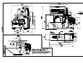
DATI TECNICI, QUOTE DI INGOMBRO,
ALLACCIAMENTI.........................................10-1
CAPITOLO 11 ................................................11-1
SCHEMI ELETTRICI.....................................11-1
CAPITOLO 13 ................................................13-1
DISEGNI PEZZI DI RICAMBIO..................13-1
CAPITOLO 14 ................................................14-1
DISTINTE CODICI.........................................14-1
GB
i:\gestione istruzione\_smacchiatrici\jolly\_4jolly_gb.doc (marzo 00)
I N D E X
CHAPTER 1......................................................1-1
SAFETY PRECAUTIONS................................1-1
CHAPTER 2......................................................2-1
MACHINE IDENTIFICATION.......................2-1
BREAKDOWNS..................................................4-7
BREAKDOWNS TO COLD SPOTTING GUNS .... 4-7
BREAKDOWNS TO THE STEAM/AIR SPOTTING
GUN ......................................................................... 4-7
BREAKDOWNS ON THE BUILT-IN
COMPRESSOR (IF FITTED) .................................. 4-7
EXHAUST FAN BREAKDOWNS.......................... 4-8
ORDERING SPARE PARTS .............................4-8
STORAGE OR DEMOLITION.........................4-9
CHAPTER 4 .....................................................4-1
INSTALLATION................................................ 4-1
CHAPTER 10 .................................................10-1
PACKING................................................................. 4-1
TRANSPORT ........................................................... 4-1
UNPACKING AND LAYING OF THE MACHINE
.................................................................................. 4-1
COMPRESSED AIR CONNECTION (FOR
MACHINE WITHOUT COMPRESSOR) ........ 4-1
STEAM AND CONDENSATION RETURN
CONNECTION (FOR MACHINES WITH
AIR/STEAM SPOTTING GUN) ........................ 4-2
ELECTRICAL CONNECTION ............................... 4-2
CONNECTION AND USE OF THE COMPRESSOR
CHAPTER 11 .................................................11-1
(FOR MACHINE WITH BUILT-IN
COMPRESSOR).................................................... 4-3
CHAPTER 13 .................................................13-1
COLD AND HOT SPOTTING GUNS ASSEMBLING
.................................................................................. 4-3
DRAWING OF SPARE PARTS ....................13-1
TECHNICAL SPECIFICATIONS,
ENCUMBRANCE, CONNECTIONS ...........10-1
ELECTRICAL DIAGRAMS .........................11-1
USE OF THE MACHINE .................................. 4-4
PRELIMINARY CONTROLS ................................. 4-4
START-UP OF THE MACHINE ............................. 4-4
USE OF THE SPOTTING TABLE AND ARM....... 4-4
USE OF THE SUCTION CABIN............................. 4-4
USING THE AIR-STEAM SPOTTING GUN ......... 4-4
TIPS ON STAIN REMOVAL .................................. 4-5
SHUTTING DOWN OF THE MACHINE ....... 4-5
MAINTENANCE................................................ 4-5
WEEKLY MAINTENANCE ................................... 4-6
SIX MONTHLY / YEARLY MAINTENANCE ...... 4-6
CHAPTER 14 .................................................14-1
CODE’S LIST .................................................14-1
F
i:\gestione istruzione\_smacchiatrici\jolly\_5jolly_fr.doc (febbraio 00)
T A B L E D E S
M A T I E R E S
CHAPITRE 1 .....................................................1-1
CONSEILS POUR LA SECURITE DES
PERSONNES ET DES CHOSES......................1-1
CHAPITRE 2 .....................................................2-1
IDENTIFICATION DE LA MACHINE….......2-1
PANNES .............................................................5-7
PANNES AUX PISTOLETS DETACHANTS A
FROID .................................................................... 5-7
PANNES AU PISTOLET DETACHANT AIR /
VAPEUR (OU PRESENT) ..................................... 5-8
PANNES AU COMPRESSEUR INCORPORE (OU
PRESENT).............................................................. 5-8
PANNES A L’ASPIRATEUR ................................ 5-9
COMMANDE DES PIECES DE RECHANGE5-9
STOCKAGE OU DEMOLITION..................5-10
CHAPITRE 5 ..................................................... 5-1
INSTALLATION...............................................5-1
CHAPITRE 10 ................................................ 10-1
EMBALLAGE........................................................ 5-1
TRANSPORT ......................................................... 5-1
DEBALLAGE ET MISE EN PLACE DE LA
MACHINE.............................................................. 5-1
BRANCHEMENT AIR COMPRIME (POUR
MACHINES SANS COMPRESSEUR) .......... 5-1
BRANCHEMENT VAPEUR ET RETOUR
CONDENSAT (POUR MACHINES AVEC
GROUPE PISTOLET AIR/VAPEUR) ............ 5-2
BRANCHEMENT ELECTRIQUE......................... 5-2
MONTAGE ET USAGE DU COMPRESSEUR
CHAPITRE 11 .................................................11-1
(POUR MACHINES AVEC COMPRESSEUR)
CHAPITRE 13 .................................................13-1
................................................................................ 5-3
MONTAGE PISTOLETS DETACHANTS A FROID
ET A CHAUD ........................................................ 5-3
USAGE DE LA MACHINE..............................5-4
VERIFICATIONS PRELIMINAIRES ................... 5-4
DEMARRAGE MACHINE.................................... 5-4
USAGE TABLE ET BRAS DETACHANT ........... 5-4
USAGE CABINE ASPIRANTE............................. 5-4
USAGE PISTOLET DETACHANT AIR-VAPEUR
................................................................................ 5-5
CONSEILS UTILS POUR LE DETACHAGE....... 5-5
OPERATIONS A EFFECTUER A LA FIN DU
TRAVAIL ...........................................................5-5
ENTRETIEN......................................................5-6
ENTRETIEN PAR SEMAINE ............................... 5-6
ENTRETIEN SEMESTRIEL/ANNUEL ................ 5-7
DONNEES TECHNIQUES, COTES DE ENCOMBREMENT, BRANCHEMENTS...........10-1
SCHEMAS ELECTRIQUES ..........................11-1
DESSINS PIECES DE RECHANGE .............13-1
CHAPITRE 14 .................................................14-1
LISTES DES CODES ...............................…...14-1
D
i:\gestione istruzione\_smacchiatrici\jolly\_6jolly_te.doc (febbraio 00)
I N H A L T
KAPITEL 1 .......................................................1-1
SICHERHEITSHINWEISE FÜR PERSONEN
UND GEGENSTÄNDE .....................................1-1
KAPITEL 2 .......................................................2-1
IDENTIFIZIERUNG DER MASCHINE ........2-1
KAPITEL 6 .......................................................6-1
INSTALLATION................................................ 6-1
VERPACKUNG ....................................................... 6-1
TRANSPORT ........................................................... 6-1
AUSPACKEN UND AUFSTELLEN DER
MASCHINE ............................................................. 6-1
DRUCKLUFTANSCHLUSS (FÜR MASCHINEN
OHNE KOMPRESSOR) ...................................... 6-2
DAMPFANSCHLUSS UND KONDENSRÜCKLAUF
(FÜR MASCHINEN MIT LUFT/DAMPF
PISTOLENEINHEIT) .......................................... 6-2
ELEKTRISCHER ANSCHLUSS............................. 6-2
MONTAGE UND GEBRAUCH DES
KOMPRESSORS (FÜR MASCHINEN MIT
KOMPRESSOR) ................................................... 6-3
MONTAGE DER KALT UND WARM
DETACHIERPISTOLEN ......................................... 6-4
GEBRAUCH DER MASCHINE ....................... 6-4
EINLEITENDE KONTROLLEN............................. 6-4
INBETRIEBNAHME ............................................... 6-4
GEBRAUCH DES TISCHES UND DES
DETACHIERARMS................................................. 6-5
GEBRAUCH DER SAUGKABINE......................... 6-5
GEBRAUCH DER DAMPF/
LUFTDETACHIERPISTOLE .................................. 6-5
NÜTZLICHE RATSCHLÄGE FÜR DIE
FLECKENENTFERNUNG ...................................... 6-5
DURCHZUFÜHRENDE BARBEITEN AM
ENDE DES GEBRAUCHS ................................ 6-6
WARTUNG..........................................................6-6
WÖCHENTLICHE WARTUNG ............................. 6-7
HALBJÄHRLICHE/JÄHRLICHE WARTUNG ...... 6-7
STÖRUNGEN......................................................6-9
STÖRUNGEN AN DEN KALTFLECKENENTFERNER-PISTOLEN ..................... 6-9
STÖRUNGEN AN DER DAMPF/LUFT
DETACHIERPISTOLE (SOFERN VORHANDEN)
.................................................................................. 6-9
STÖRUNGEN AM EINGEBAUTEN KOMPRESSOR
(SOFERN VORHANDEN) ...................................... 6-9
BESTELLUNG DER ERSATZTEILE............6-10
AUSSERBETRIEBSETZUNG UND ABBAU 6-11
KAPITEL 10 .................................................. 10-1
TECHNISCHE DATEN, RAUMBEDARF,
ANSCHLÜSSE .................................................10-1
KAPITEL 11 ...................................................11-1
ELEKTRISCHES SCHALTPLAN ................11-1
KAPITEL 13 ...................................................13-1
TEILSCHNITTZEICHNUNGEN DER
ERSATZTEILEN ............................................13-1
KAPITEL 14...................................................14-1
VERZEICHNIS DER CODES.......................14-1
E
i:\gestione istruzione\_smacchiatrici\jolly\_7jolly_sp.doc (febbraio 00)
Í N D I C E
CAPÍTULO 1 ....................................................1-1
ADVERTENCIAS PARA LA SEGURIDAD DE
LAS PERSONAS Y DE LAS COSAS ..............1-1
CAPÍTULO 2 ....................................................2-1
IDENTIFICACIÓN DE LA MÁQUINA…......2-1
CAPÍTULO 7 ....................................................7-1
INSTALACIÓN .................................................. 7-1
EMBALAJE ............................................................. 7-1
TRANSPORTE......................................................... 7-1
DESEMBALAJE Y UBICACIÓN DE LA MÁQUINA
.................................................................................. 7-1
CONEXIÓN AIRE COMPRIMIDO (SOLO PARA
MÁQUINAS SIN COMPRESOR) ..................... 7-1
CONEXIÓN DEL VAPOR Y RETORNO DE
CONDENSADOS (PARA MÁQUINAS CON
GRUPO PISTOLA AIRE/VAPOR) ................... 7-2
CONEXIÓN ELÉCTRICA....................................... 7-2
MONTAJE Y USO DEL COMPRESOR (PARA
MÁQUINAS CON COMPRESOR) ................... 7-3
MONTAJE DE LAS PISTOLAS
DESMANCHADORAS EN FRÍO Y EN CALIENTE
.................................................................................. 7-3
EMPLEO DE LA MÁQUINA ........................... 7-4
VERIFICACIONES PRELIMINARES .................... 7-4
PUESTA EN MARCHA DE LA MÁQUINA .......... 7-4
EMPLEO DE LA MESA Y DEL BRAZO DE
DESMANCHAR ...................................................... 7-4
EMPLEO DE LA CABINA ASPIRANTE ............... 7-5
EMPLEO DE LA PISTOLA DESMANCHADORA
AIRE-VAPOR .......................................................... 7-5
CONSEJOS ÚTILES SOBRE EL DESMANCHADO
.................................................................................. 7-5
OPERACIONES A REALIZAR AL FINAL DEL
TRABAJO ........................................................... 7-6
MANTENIMIENTO ...........................................7-6
MANTENIMIENTO SEMANAL ............................ 7-7
MANTENIMIENTO SEMESTRAL/ANUAL ......... 7-7
AVERÍAS .............................................................7-8
AVERÍAS EN LAS PISTOLAS
DESMANCHADORAS EN FRÍO ........................... 7-8
AVERÍAS EN LA PISTOLA DESMANCHADORA
AIRE / VAPOR (SI SE ENCUENTRA PRESENTE)
.................................................................................. 7-8
AVERÍAS EN EL COMPRESOR INCORPORADO
(SI SE ENCUENTRA PRESENTE)......................... 7-8
AVERÍAS EN EL ASPIRADOR ............................. 7-9
PEDIDO DE REPUESTOS ................................7-9
ALMACENAJE O DEMOLICIÓN.................7-10
CAPÍTULO 10 .............................................. 10-1
DATOS TÉCNICOS, TAMAÑO,
CONEXIONES ................................................10-1
CAPÍTULO 11 ................................................11-1
ESQUEMAS ELÉCTRICOS ........................11-1
CAPÍTULO 13 ................................................13-1
DIBUJOS DE LOS REPUESTOS ..................13-1
CAPÍTULO 14 ................................................14-1
LISTAS DE LOS CÓDIGOS ..........................14-1
Capitolo 7 LISTAS DE LOS códigos...........................14-1
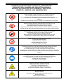
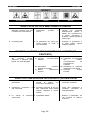
CAPITOLO 1
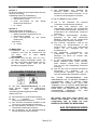
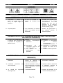
SEGNALI DI PRESCRIZIONE, PERICOLO E INDICAZIONE
PRESCRIPTION, DANGER AND INDICATION SIGNALS
SIGNAUX DE PRESCRIPTION, DANGER ET INDICATION
VERBOTS-, GEBOTS- UND WARNZEICHEN
Divieto di togliere i carter di protezione con impianto funzionante
Do not remove protection covers when machine is working.
Abnahme der Schutzgehäuse bei anlaufender Anlage verboten
Défense d’enlever les couvercles de protection pendant le fonctionnement de la
machine.
Prohibido quitar la tapa de protección durante el funcionamiento de la maquina.
Divieto di eseguire interventi di manutenzione a macchina in moto
Do not effect maintenance when machine is working.
Wartungseinsätze bei anlaufender Anlage verboten
Défense d’exécuter toutes entretiens pendant le fonctionnement de la machine.
Prohibido efectuar todos mantenimientos durante el funcionamiento de la maquina.
Vietata l’apertura del quadro elettrico al personale non autorizzato.
Authorized personnel only can open the electric panel.
Öffnung des Gehäuses für Unbefugte verboten.
Défense d’ouvrir le cadre électrique par le personnel non autorisé.
Prohibido abrir el tablero eléctrico para obreros no autorizados
Vietato utilizzare acqua per spegnere l’incendio.
Do not extinguish with water
Mit Wasser löschen verboten
Défense d’eteindre avec de l’eau.
Prohibido apagar con agua
Obbligo di riposizionare i carter di protezione prima di azionare l’impianto
Protection covers must be put on before using the machine.
Vor Inbetriebsetzung der Anlage Schutzgehäuse wiedereinbauen
Il est obligatoire de remettre le couvercle de protection avant d’actionner la machine.
Está obligatorio reponer las tapas de protección antes que se ponga en marcha la
maquina.
Consultare il manuale d’uso, lo schema elettrico e le procedure.
Consult the instruction’s manual, the electric diagram and procedures.
Betriebsanweisung, Schaltschema und Vorgänge lesen
Consulter le manuel d’emploi.
Consultar el manual d’empleo.
Attenzione pericolo di scottature alle mani
High temperatures! Possibility of burning!
Warnung vor Handverbrennungen
Hautes températures! Danger de brûlures!
Temperaturas elevadas! Peligro de quemaduras!
Quadro in tensione
Danger: electricity
Warnung vor gefährlicher elektrischer Spannung 380 V
Danger électrique
Peligro: Tensión eléctrica
Pag 1-1
CAPITOLO 1
recueil désigné pour le recyclage des rebuts électriques
et électroniques.
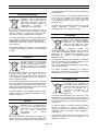
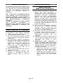
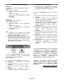
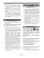
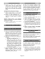
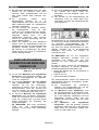
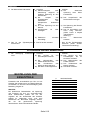
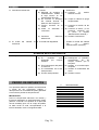
INFORMAZIONI PER LO SMALTIMENTO
DELL’APPARECCHIATURA
L’etichetta con il contenitore di
spazzatura mobile barrato presente
sul prodotto, indica che il prodotto non
deve essere smaltito tramite la
convenzionale
procedura
di
smaltimento dei rifiuti domestici.
Per evitare eventuali danni per l’ambiente e per la
salute umana, il prodotto deve essere separato dagli
altri rifiuti domestici e consegnato al punto di raccolta
designato per il riciclo dei rifiuti elettrici o elettronici.
Le recueil diversifié et le recyclage des pièces de rebut
servent pour la conservation des résources naturelles
et à préserver l’habitat et le salut des gens.
L’écoulement abusif du produit sera poursuivi aux
termes de la loi.
Pour tout autre renseignement concernent les points de
recueils disponibles, s’adresser à l’organisme
compétent local ou au revendeur du produit,
INFORMATION ÜBER ENTSORGUNG VON
ALTGERÄTEN
La raccolta differenziata ed il riciclo degli apparecchi di
scarto servirà a conservare le risorse naturali ed a
salvaguardare l’ambiente e la salute delle persone. Lo
smaltimento abusivo del prodotto sarà perseguito a
norma di legge.
Per maggiori dettagli sui centri di raccolta disponibili
contattare l’ente locale competente o il rivenditore del
prodotto.
INFORMATION FOR THE DISPOSAL OF THE
EQUIPMENT
The label showing the crossed mobile
garbage container on the product,
points out that the product must not be
disposed through the conventional
procedure of disposal of the domestic
waste.
To avoid possible damage to the environment and for
improved human health, the product has to be
separated from the other domestic waste and delivered
to the designated collection point for the recycling of
electric or electronic waste.
Das auf dem Produkt befindliche
Etikett, das eine durchgestrichene
Abfalltonne auf Rädern darstellt,
weist auf das Verbot hin, dieses
Produkt als Hausabfall zu entsorgen.
Um
eventuelle
Umwelt–
und
Gesundheitsschäden zu vermeiden, muß das Produkt
von anderen Hausabfällen getrennt werden und zur
Entsorgung an zuständige Recyclingfirmen bzw.
Sammelorte für Elektro- und Elektronik-Altgeräte
übergeben werden.
Die getrennte Sammlung und Recycling der Altgeräte
dient zur Bewahrung des natürlichen Reichtums und
zum Schutz von Umwelt und Gesundheit.
Eine nicht umweltgerechte Beseitigung des Produkts
wird gesetzlich bestraft.
Für weitere Information betreffend der verfügbaren
Sammelorte, wenden sich an die örtliche zuständigen
Behörden oder an Ihren Produkthändler.
INFORMACIONES POR LA LIQUIDACIÓN DE LA
INSTRUMENTACIÓN
The diversified collection and the recycling of rejected
instruments will serve to preserve the natural resources
and to safeguard the environment and the health of the
people. The unauthorized disposal of the product will be
prohibited according to the local laws.
La etiqueta con el contenedor de
basura móvil barrato presente sobre
el producto, indica que el producto no
tiene que ser eliminado por el
convencional
procedimiento
de
liquidación
de
los
rechazos
domésticos.
For greater details on the available collection centres
please contact the competent local authority or the
retailer of the product.
Para evitar eventuales daños por el entorno y por la
salud humana, el producto tiene que ser separado por
los demás rechazos domésticos y remitidos al punto de
colección designado por el reciclo rechazos eléctricos o
electrónicos.
RENSEIGNEMENTS POUR L’ECOULEMENT DE LA
MACHINE
L’Etiquette avec la poubelle barrée
qu’il y a sur le produit, signifie que le
produit même ne peut pas être écoulé
par
le
canal
conventionnel
d’écoulement
des
ordures
domestiques.
Pour éviter d’éventuels dommages pour l’habitat et le
salut de l’homme, la machine doit être séparée des
autres ordures domestiques et livrée jusqu’au point de
La colección distinta y el reciclo aparatos de descarte
servirá a conservar los recursos naturales y a
salvaguardar el entorno y la salud de las personas. La
liquidación abusiva del producto será perseguida a
norma de ley.
Para mayores detalles sobre los centros de colección
disponible contactar al ente local competente o el
detallista del producto.
Pag. 1-2
ITALIANO
CAPITOLO 3
ITALIANO
Capitolo 3 .
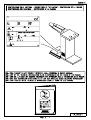
INSTALLAZIONE
DISIMBALLAGGIO E POSA
DELLA MACCHINA
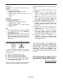
IMBALLO
La macchina può essere imballata in tre modi:
Procedere nel seguente modo:
1) CON FONDALE IN LEGNO E MACCHINA
AVVOLTA IN CELLOPHANE: formato da un
fondale (che ne permette il
sollevamento e
lo spostamento con mezzi meccanici
(paranchi, muletti). La macchina, imbullonata
sul fondale nei piedini d’ancoraggio, è avvolta
con un sacco di polietilene (PE) fissato con
graffette sul fondale.
2) CON INDUPACK: con l’aggiunta di un
involucro in cartone bloccato con regge
metalliche su pallet.
3) SOLO INCARTATURA
TRASPORTO
Subito
al
ricevimento
della
macchina
imballata, notificare per scritto al trasportatore
eventuali danni subiti dall’imballo durante il
trasporto.
Infatti, qualora tali danni abbiano interessato
anche la macchina, l’assicurazione del corriere
risponderà solo se tali danni presunti sono stati
subito segnalati.
Tutte le operazioni di installazione devono
essere eseguite da personale qualificato, munito
delle necessarie protezioni (guanti, protezioni
antinfortunistiche etc.).
Non usare getti di acqua contro la macchina per
nessun motivo ed evitare bruschi movimenti o
urti violenti.
La macchina non deve essere trasportata da
braccia umane, bensì con l'ausilio di muletti o
paranchi meccanici.
Trasportare la macchina completa di imballo nel
luogo più prossimo al punto di installazione e
procedere al suo disimballaggio.
a) Togliere, se esistente, l'indupack munendosi
di appositi attrezzi meccanici.
b) Togliere la copertura in polietilene (PE) che
avvolge la macchina.
c) Verificare che la macchina non abbia subito
danneggiamenti durante il trasporto.
d) Asportare dal fondale tutti gli accessori che
non sono fissati o imbullonati sul bancale
perché, spostando la macchina dal bancale,
possono
cadere
danneggiando
cose,
persone o animali.
e) Togliere i bulloni che fissano i piedini della
macchina sul fondale.
f) Imbragare la macchina con due funi
(verificare che siano idonee al peso totale
della macchina rilevabile dal cartellino dati
tecnici), l'una nella parte posteriore, l'altra
nella parte anteriore della macchina; quindi,
con l'ausilio di un muletto o paranco
meccanico, sollevare la macchina e
posizionarla
nel
luogo
destinato
all'installazione senza più muoverla con
braccia umane.
g) Montare la forma braccio smacchiante “POS.
87“, inserendola nell’apposito supporto posto
sul tavolo “POS. 88“ (vedi pag. 10-5).
h) Montare il telaio poggia-indumenti “POS. 89“
(vedi pag. 10-5) fissandolo con le tre viti in
dotazione agli appositi supporti posti sul
basamento della macchina.
i) Montare l’eventuale lampada “POS.90” (vedi
pag. 10-5) fissando il relativo braccio al
supporto sulla macchina per mezzo delle
apposite viti.
j) Al termine dell'installazione rimontare con
cura i pannelli e le protezioni della macchina.
Devono essere osservate alcune misure di
distanza dalle pareti e dalle altre macchine, al fine
di garantire una lavorazione più scorrevole ed una
perfetta manutenzione. La macchina non
necessita di alcun ancoraggio al pavimento.
Si raccomanda di sistemarla perfettamente in
piano.
Pag. 3-1
ITALIANO
CAPITOLO 3
ITALIANO
b) Venga usato del tubo in ferro o rame del
diametro minimo consigliato (1/2” GAS).
c) I tubi siano a pendenza costante, i raggi
delle curve siano di almeno 50 mm. (≅ 2
inches), non esistano strozzature nella
tubazione e la lunghezza di ciascun tubo
non superi i 2,5 metri (100 inches).
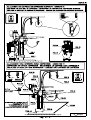
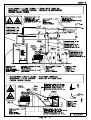
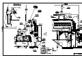
COLLEGAMENTO ARIA
COMPRESSA
(PER MACCHINE SENZA COMPRESSORE)
(VEDI DISEGNO A PAG. 10-3)
La macchina deve essere alimentata con aria
compressa pulita, senza condense né oli, ed
avente una pressione di 8-10 bar (116-145 psi).
Predisporre un tubo in ferro zincato o rilsan da
3/8”GAS fino ad 1 metro dalla macchina.
Alla sua estremità montare un rubinetto a sfera a
3 vie oppure a slitta “POS. 25”.Questo rubinetto
a 3 vie permette di alimentare la macchina
(posizione 1=ON=OK) oppure di disattivarla
(posizione 0=OFF=STOP), scaricando l’aria
rimasta nella macchina attraverso il silenziatore.
In questo modo, qualora fosse necessario
eseguire una qualsiasi manutenzione alla
macchina, si ha la garanzia, ruotando il rubinetto
in posizione 0=OFF=STOP (oppure facendo
scivolare la ghiera), che non esista più alcun
pericolo di natura pneumatica (getti di aria,
movimenti di pistoni, etc.).
Mediante un tubo in rilsan di ∅interno=8mm (≅0,3
inches) resistente ad almeno 20 bar (290 psi) di
pressione, collegare il rubinetto al raccordo
alimentazione aria compressa “POS. 2”.
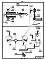
ALLACCIAMENTO VAPORE E
RITORNO CONDENSA
(PER MACCHINE CON GRUPPO PISTOLA
ARIA/VAPORE)
Tutte queste precauzioni sono indispensabili per
evitare risucchi d’acqua e, qualora non fossero
realizzabili,
è
necessario
effettuare
un
collegamento tradizionale, cioè con scaricatore
di condensa, come illustrato nel disegno di pag.
10-4 (figura in alto).
Per quest’ultimo tipo di collegamento, derivare
dalla parte alta della conduttura centrale di vapore
un tubo di ferro da 1/2" GAS e farlo arrivare a 100
cm dalla macchina. All’estremità di questo tubo
montare un rubinetto a sfera “POS. 67”, onde
poter escludere la macchina dall’impianto.
Il collegamento del rubinetto a sfera al raccordo
entrata vapore “POS. 4” si può fare con un tubo
di rame avente un diametro interno di 10 mm,
oppure con un tubo flessibile idoneo per vapore.
Vi ricordiamo che la macchina funziona con
vapore alla pressione di 4-6 bar (60-90 psi)
perciò, se la macchina viene allacciata ad un
generatore di vapore funzionante ad una
pressione più elevata, è necessario installare un
riduttore di pressione.
Collegare al raccordo ritorno condensa “POS. 3”
uno scaricatore di condensa da 1/2" GAS a
secchiello rovesciato con filtro (SPIRAX SARCO
HM 007 oppure JUCKER SA8).
A valle dello scaricatore si deve montare una
valvola di ritegno a clappè onde evitare
contropressioni allo scaricatore.
E’ indispensabile montare un rubinetto a sfera
“POS. 68” sulla tubazione di ritorno condensa
(tubo da 1/2" GAS) onde permettere l’esclusione
della macchina dall’impianto.
COLLEGAMENTO ELETTRICO
(VEDI DISEGNO A PAG. 10-4)
Come illustrato nel disegno di pag. 10-4 (figura in
basso), è possibile collegare la macchina ad una
piccola caldaia in modo diretto, cioè senza
scaricatore.
E’ però indispensabile che:
a) La quota “H” dal pavimento del foro di scarico
condensa “POS. 3” superi di almeno 200 mm
(8 inches) il livello acqua “K” in caldaia,
misurato dallo stesso piano.
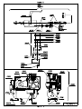
(VEDI DISEGNO A PAG. 10-5)
Accertarsi che la tensione e frequenza di linea
corrispondano a quelle segnate sulla targa dati
tecnici della macchina (vedere pag. 2-1).
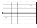
Predisporre una linea elettrica dimensionata
come indicato dalla tabella riportata nel disegno
a pag. 10-5.
Pag. 3-2
ITALIANO
CAPITOLO 3
La linea di corrente dovrà essere dotata di un
interruttore
automatico
magnetotermico
differenziale da 30 mA, con presa e spina ad
interblocco meccanico.
Si fa obbligo, pena la decadenza della garanzia,
di collegare la macchina ad una buona messa a
terra secondo le normative vigenti.
Controllare, prima del collaudo iniziale, che i
morsetti di tutti i componenti elettrici non si siano
allentati durante il trasporto.
Dopo il collegamento, verificare il senso di
rotazione del compressore (solo per macchina
con compressore) e qualora fosse errato,
invertire tra loro due delle tre fasi in ingresso.
N.B.: È indispensabile essere sicuri del corretto
senso di rotazione del compressore, perché, se
ruota
in
senso
errato,
si
danneggia
irreparabilmente. In tali casi il fabbricante non può
accettare richieste di sostituzione in garanzia.
Rimontare tutte le pannellature e le protezioni
della macchina.
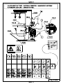
MONTAGGIO E USO DEL
COMPRESSORE
(PER MACCHINE CON COMPRESSORE)
(VEDI DISEGNO A PAG. 10-3)
Disimballare il compressore dalla scatola in cui è
contenuto e conservare con cura le schede
tecniche e di collaudo allegate.
Montare
con
attenzione
il
compressore
imbullonandolo sui quattro piedini in gomma già
fissati sul basamento della macchina.
Collegare il tubetto d’alimentazione dell’aria
compressa dal raccordo della serpentina aria
“POS. 2” al raccordo uscita aria del compressore
“POS. 7”.
Per accendere il compressore sollevare il
pulsante del pressostato “POS. 78” ed azionare
il
pulsante
di
marcia
dell’interruttore
magnetotermico “POS. 79”: il compressore
caricherà aria fino a raggiungere una pressione
massima di 10 bar circa.
Per spegnere il compressore premere il
pulsante del pressostato “POS.78” ottenendo
anche lo scarico automatico della testata del
compressore.
Azionare
il
pulsante
rosso
“POS.80”
dell’interruttore magnetotermico solo a fine
giornata.
NOTE PER L’UTILIZZO
COMPRESSORE:
ITALIANO
DEL
SERBATOIO
Un corretto utilizzo del serbatoio a pressione
d'aria compressa è premessa indispensabile per
garantire la sicurezza; a tale scopo l'utilizzatore
deve ma non solo:
a) Utilizzare correttamente il serbatoio nei limiti
di pressione e di temperatura di progetto che
sono riportati sulla targa del Costruttore e sul
documento di collaudo che deve essere
conservato con cura.
b) Evitare di effettuare saldature sul mantello
cilindrico e sul fondo.
c) Garantirsi che il serbatoio sia sempre
corredato di efficienti e sufficienti dispositivi
di sicurezza e provvedere, in caso di
necessità, alla loro sostituzione con altri di
equivalenti caratteristiche. In particolare la
valvola di sicurezza deve essere applicata
direttamente sul recipiente senza possibilità
di interposizione, deve avere una capacità di
scarico superiore alla quantità di aria che può
essere immessa nel recipiente, essere tarata
e piombata alla pressione di bollo del
serbatoio. Sul manometro, la pressione di
bollo deve essere indicata con un segno
rosso.
d) Evitare scrupolosamente di collocare il
serbatoio in locali non sufficientemente
aerati, in zone esposte a sorgenti di calore e
nelle vicinanze di sostanze infiammabili.
e) Evitare che il serbatoio durante l'esercizio
sia soggetto a vibrazioni che possono
generare rotture per fatica.
f) Scaricare quotidianamente la condensa che
si forma all'interno del serbatoio e verificare
ogni tre mesi l'insorgere di eventuali
corrosioni interne nel serbatoio. Tuttavia lo
spessore effettivo del recipiente dopo la
corrosione non dovrà essere inferiore a 3-4
mm.
g) Agire in ogni caso con senno e
ponderatezza in analogia ai casi previsti.
E'
TASSATIVAMENTE
VIETATA
LA
MANOMISSIONE DEL SERBATOIO ED OGNI
UTILIZZAZIONE IMPROPRIA.
Si rammenta all'utilizzatore che è comunque
tenuto a rispettare le leggi sull'esercizio degli
apparecchi a pressione in vigore nel Paese di
utilizzo.
Pag. 3-3
ITALIANO
CAPITOLO 3
MONTAGGIO DELLE PISTOLE
SMACCHIANTI A FREDDO E A
CALDO
(VEDI DISEGNO A PAG. 10-3)
Montaggio pistole smacchianti a freddo
“POS. 13”, “POS. 21”:
a) Montare il braccio di sostegno delle pistole
sul supporto “POS.18” servendosi dei due
bulloni in dotazione.
b) Collegare i tubetti corti, collegati a ciascuna
pistola, nei relativi raccordi “POS.19” dell’aria
compressa. Collegare anche i tubetti più
lunghi, collegati a ciascuna pistola, ai
serbatoi per prodotti smacchianti fissati sulla
parte posteriore del tavolo.
Montaggio pistole smacchianti aria/vapore:
a) Montare il gruppetto ferrovapor con pistola
aria vapore “POS. 33” sul supporto “POS.17”
servendosi delle due viti in dotazione.
b) Collegare il tubetto di alimentazione dell’aria
compressa dal gruppetto pistola aria vapore
“POS. 91” al raccordo entrata aria
compressa “POS.15”.
Montaggio pistola asciugatrice ad aria
compressa (data in dotazione in alternativa
alla
pistola
elettrica
smacchiante
ad
aria/vapore):
a) Collegare la pistola “POS. 22” al raccordo
entrata aria compressa “POS. 15”.
USO DELLA MACCHINA
VERIFICHE PRELIMINARI
(VEDI DISEGNI PAGG. 10-3, 4)
a) Nel caso di macchina senza compressore
incorporato, controllare che il rubinetto a
sfera di alimentazione aria compressa “POS.
25” sia aperto e scaricare l’eventuale
condensa depositatasi nella tazza filtro aria
compressa, agendo sul relativo rubinetto
“POS. 26”.
ITALIANO
b) Nel caso di macchina con compressore
incorporato:
•
Scaricare
la
condensa
formatasi
nel serbatoio tramite il rubinetto “POS.
70”.
•
Verificare che il livello dell’olio del
monoblocco compressore arrivi alla
mezzaria dell’apposita spia. Qualora ne
mancasse, raboccare il livello con olio
SAE 40 (Q8 VERDI 150S, Agip ACER
150 o similari). Se l’olio introdotto
dovesse superare il livello massimo,
l’eccedenza
verrà
espulsa
dal
compressore attraverso gli sfiatatoi; è
quindi consigliabile non superare tale
livello.
c) Nel caso di macchina con gruppo pistola
aria/vapore, controllare che i rubinetti a
sfera montati sulle tubazioni di alimentazione
vapore “POS. 67” e ritorno condensa “POS.
68” siano aperti.
Inizialmente, con la macchina fredda, il vapore in
arrivo si condenserà rapidamente; è, quindi,
consigliabile attendere qualche minuto prima di
iniziare la lavorazione, affinché tutta la condensa
formata si possa scaricare.
Non
attenendoVi
a
questa
norma,
l’abbondante
condensa
che
si
forma
uscirebbe dalla pistola vapore danneggiando il
capo.
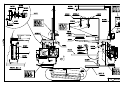
ACCENSIONE MACCHINA
(VEDI DISEGNO A PAG. 10-5)
Procedere nel seguente modo:
a) Accendere l’interruttore generale previsto
sulla linea elettrica di alimentazione.
b) Inserire
l’interruttore
azionamento
aspiratore “POS. 24” o schiacciare il pedale
“POS. 86“ a seconda che si desideri
un’aspirazione continua o a discrezione
dell’operatore.
c) Nel caso di macchina con compressore
incorporato, azionare il pulsante di marcia
dell’interruttore magnetotermico “POS. 79” e
sollevare il pulsante del pressostato “POS.
78”.
d) Nel caso di macchina con gruppo
pistola
aria/vapore,
accendere
l’interruttore “POS. 14“ per poter attivare la
pistola.
Pag. 3-4
ITALIANO
CAPITOLO 3
USO DEL TAVOLO E DEL
BRACCIO SMACCHIANTI
(VEDI DISEGNO PAG. 10-5)
Per lavorare dal braccio smacchiante “POS.87“
occorre ruotarlo al centro del tavolo. Per lavorare
sul tavolo occorre ruotare il braccio in senso
orario per portarlo fuori dalla posizione di lavoro.
USO DELLA CABINA
ASPIRANTE
(VEDI DISEGNO PAG. 13-2)
La cabina aspirante garantisce l’aspirazione dei
vapori dei prodotti chimici e dei saponi detergenti
usati per la smacchiatura.
ITALIANO
b) Premere il pulsante sinistro della pistola per
ottenere la fuoriuscita del vapore. Per i primi
secondi il vapore sarà misto ad acqua; è
quindi necessario scaricare la pistola per
qualche secondo, finché non si sarà ben
riscaldata.
c) Dirigere il getto di vapore sul tessuto a cui è
stato applicato il prodotto smacchiante,
muovendo la pistola in senso rotatorio. Una
abbondante
vaporizzazione
dissolve
istantaneamente le macchie solubili in
acqua.
d) Per asciugare la zona smacchiata, premere
l’eventuale pulsante destro della pistola,
ottenendo la fuoriuscita di aria compressa.
Muovere rapidamente la pistola avanti e
indietro in un movimento a zig-zag, in modo
che l’umidità venga espulsa con l’aria. La
forte aspirazione concentrata favorisce un
rapido asciugamento.
Per mettere in funzione la cabina occorre:
a) Sbloccare il tasto di stop “POS.51” nel caso
fosse bloccato; in tal modo si metterà
immediatamente in funzione l’aspiratore della
cabina “POS.52” e si favorirà l’uso delle
pistole smacchianti a freddo “POS. 13”, “POS.
21”.
b) Accendere
l’interruttore
della
lampada
“POS.50” e ruotare quest’ultima affinché il
fascio luminoso illumini la zona di lavoro.
c) Qualora ci fosse in dotazione la pistola
elettrica
per
smacchiatura
“POS.53”,
collegare la relativa spina elettrica nella
presa “POS.54” per permetterne l’uso.
L’aria aspirata dalla cabina e quella aspirata dal
tavolo e dal braccio smacchiante viene purificata
dal filtro a carboni attivi “POS. 55” ed espulsa
priva di vapori nocivi.
La durata di questo filtro è legata ai prodotti
impiegati e alle ore di lavoro; si raccomanda
comunque di rigenerarlo almeno una volta
all’anno.
USO DELLA PISTOLA
SMACCHIANTE ARIA-VAPORE
Procedere come segue:
a) Sistemare la parte smacchiante sulla punta
del tavolo o della forma per braccio e premere
il pedale di aspirazione “POS. 86” (vedi pag.
10-5).
CONSIGLI UTILI PER LA
SMACCHIATURA
(VEDI DISEGNI PAG. 10-3)
Attenersi ai consigli riportati sui flaconi dei
prodotti per la smacchiatura.
Premesso che i migliori risultati si ottengono con
la pratica che si acquisisce con l’uso, quanto
sotto esposto può anticipare i tempi di
apprendimento:
a) Le pistole smacchianti “POS. 13” e “POS. 21”
devono agire alla distanza di circa ½ cm dal
tessuto. A tale distanza si ottiene la massima
penetrazione della miscela aria-acqua, che,
proiettata sulla parte da smacchiare ad una
pressione di 8-10 bar (116-145 psi), crea una
forza
d’urto
capace
di
asportare
meccanicamente ogni particella estranea al
tessuto. Poichè la smacchiatura si ottiene in
gran parte per effetto dell'azione meccanica
della miscela aria-acqua, è consigliabile
usare la minor quantità di acqua possibile;
ciò
agevola
anche
il
successivo
asciugamento. Per ottenere la massima
azione meccanica con l’impiego del minor
liquido possibile, si deve agire gradualmente
sulla leva della pistola sino ad ottenere
un’uscita spilliforme della miscela aria-acqua.
b) Per macchie particolarmente resistenti o
molto vecchie, si rende indispensabile l’uso
di un buon sapone neutro. Il sapone
cosparso sulla macchia ne favorisce lo
scioglimento e la solubilizzazione.
Pag. 3-5
ITALIANO
c)
d)
e)
CAPITOLO 3
Per macchie particolari la cui natura è
identificata (es. macchie di rossetto,
sangue, vernici, grasso etc.), usare i
prodotti
specifici
forniti
dalle
ditte
specializzate.
Per le operazioni di asciugamento del
tessuto, le pistole asciugatrici “POS. 22” o
“POS. 33” devono essere impugnate in
modo che l’ugello sia perpendicolare ed
appoggiato al tessuto, così da favorire la
massima
penetrazione
senza
inutili
dispersioni. Contemporaneamente occorre
azionare l’aspirazione.
Se ci fosse in dotazione il gruppo pistola
aria/vapore “POS. 33”, può essere usato un
getto di vapore sul tessuto a cui è stato
applicato il prodotto smacchiante in modo
da accelerarne l’azione. Tramite questa
pistola è anche possibile togliere macchie
di leggera entità.
OPERAZIONI DA COMPIERE
AL TERMINE DEL LAVORO
(VEDI DISEGNI A PAGG. 10-3 E 10-4)
a) Nel caso di macchina senza compressore
incorporato, chiudere il rubinetto a sfera
montato sulla rete di alimentazione aria
compressa “POS. 25”.
b) Nel caso di macchina con gruppo
pistola aria/vapore, chiudere i rubinetti a
sfera
montati
sulle
tubazioni
di
alimentazione vapore “POS. 67” e ritorno
condensa
“POS.
68”
e
disinserire
l’interruttore di accensione pistola “POS.14”
(vedi pag. 10-5).
c) Nel caso di macchina con compressore
incorporato, spegnere il compressore
premendo il pulsante del pressostato
“POS. 78”, in tal modo si ottiene lo
scarico automatico della testata del
compressore.
N.B.: Azionare il pulsante rosso “POS. 80”
dell’interruttore magnetotermico solo a fine
giornata.
d) Nel caso di macchina con cabina
aspirante, spegnere l’interruttore della
lampada “POS. 50” e bloccare il tasto di
stop “POS. 51”.
e) Disinserire
l’interruttore
d’azionamento
dell’aspiratore “POS. 24” (vedi pag. 10-5),
quindi l’interruttore generale previsto sulla
linea di alimentazione.
ITALIANO
MANUTENZIONE
Quanto segue è di vitale importanza per avere
una macchina sempre in perfetta efficienza, che
vi darà sempre il massimo rendimento,
evitandovi dispendiosi fermi-macchina.
La prima parte di questa rubrica è divisa in
capitoli a seconda della maggiore o minore
frequenza delle singole manutenzioni.
N.B.:
La
frequenza
da
noi
riportata
(settimanale, mensile, etc.) è indicativa e si
riferisce ad una macchina che lavori in condizioni
“normali”.
Sarete poi Voi stessi a stabilire l’esatta cadenza
delle operazioni di manutenzione, in funzione dei
seguenti parametri:
• quantità di lavoro eseguito dalla macchina;
• pulviscolo nell’aria;
• altre particolari condizioni.
Tutte le operazioni di manutenzione vanno
eseguite a macchina completamente spenta ed
in particolare:
a) L’interruttore generale previsto sulla linea
elettrica deve essere spento e la spina deve
essere tolta dalla presa.
b) Per le macchine senza compressore, deve
essere chiuso il rubinetto di alimentazione
aria compressa “POS.25“ (vedi pag. 10-3) e
deve essere scaricata l’aria rimasta nella
macchina agendo sullo sfiato del filtro “POS.
26” (vedi pag. 10-3).
c) Per le macchine con compressore
incorporato, deve essere scaricata tutta
l’aria compressa accumulata nella macchina
agendo sul rubinetto di scarico “POS. 70”
(vedi pag. 10-4).
d) Per le macchine con gruppo pistola
aria/vapore, devono essere chiusi i rubinetti
a sfera di alimentazione vapore “POS. 67” e
ritorno condensa “POS. 68” (vedi pag.
10-4).
e) Bisogna lasciare raffreddare le parti calde
della macchina (tubi interni, valvole,
eventuale caldaia, etc.) al fine di non
ustionarsi.
Solo seguendo tutte queste precauzioni ed altre
dettate da particolari condizioni contingenti, è
possibile eseguire le manutenzioni sulla
macchina in assoluta sicurezza, ricordandosi
che “la prudenza non è mai troppa”.
Pag. 3-6
ITALIANO
CAPITOLO 3
Per rendere più evidenti i pericoli, abbiamo posto
nei punti critici della macchina, dei simboli adesivi
il cui significato viene spiegato dettagliatamente
nella pagina rossa all'inizio di questo manuale
(“Segnali
di
prescrizione,
pericolo
e
indicazione”).
N.B.: In ogni caso, le manutenzioni devono
essere effettuate solo ed esclusivamente da
personale competente, il quale risponde in
prima persona dell'incolumità propria e di
altre
persone/animali/cose
eventualmente
interessa-te.
La legge, e specialmente le ultime direttive
CEE,
puniscono
severamente
il
proprietario della macchina qualora faccia
eseguire manutenzioni a personale non
competente.
MANUTENZIONE SETTIMANALE
a) Controllare il filtro dell’aria compressa,
scaricare l’acqua, pulire la tazza filtro.
b) Tramite l’apposito rubinetto “POS. 70” (vedi
pag. 10-4), scaricare la condensa che si è
formata all’interno dell’eventuale serbatoio
compressore.
c) Se la macchina è dotata di compressore,
controllare il livello dell’olio nella testata del
compressore. Se necessario, rabboccare il
livello con olio SAE 40 (Agip ACER 150, Q8
VERDI 150 o similari). Consigliamo di
sostituire l’olio dopo un rodaggio di 100 ore
e successivamente ogni 400 ore di
funzionamento effettivo.
d) Pulire il filtro aria della testata ogni 100 ore e
sostituirlo ogni 6 mesi.
e) Scaricare la condensa formatasi nella
serpentina di raffreddamento aprendo il
rubinetto di scarico “POS. 40” (vedi pag.
10-3).
ITALIANO
MANUTENZIONE
SEMESTRALE/ANNUALE
a) Una perfetta aspirazione, attraverso le
reticelle
dei
piani
smacchianti,
è
indispensabile per una buona smacchiatura:
un’eventuale diminuzione dell'aspirazione,
attraverso tali reticelle, pregiudicherebbe
quindi il buon esito della smacchiatura
stessa. Si consiglia pertanto, ogni qualvolta
si notasse una diminuzione nell'aspirazione,
di procedere a smontare le reticelle “POS. 27”
e “POS. 28” (vedi pag. 10-2) e sottoporle ad
un’accurata pulizia liberandone i fori da
eventuali incrostazioni.
b) Pulire il condotto d’aspirazione del tavolo e
del braccio ed il serbatoio separatore
condense “POS. 34” (vedi pag. 10-4)
smontando lo stesso separatore. Effettuare
poi con cura il montaggio dei particolari.
c) Controllare lo stato di conservazione di tutte
le targhette della macchina (di pericolo o
d’istruzione); qualora fossero deteriorate, è
indispensabile
procedere
alla
loro
sostituzione.
d) Solamente per macchine collegate ad una
fonte di vapore: procedere alla pulizia del
filtro posto sulla tubazione di ritorno
condensa.
e) Manutenzione pistole smacchianti a
freddo e vaschette liquidi (vedi disegno
a pag. 13-4): la pulizia dei filtri deve essere
fatta ogni qualvolta si nota una diminuzione
d’afflusso di liquido smacchiante alle pistole.
Procedere come segue:
• Tappare con il dito pollice il foro d’uscita
della miscela aria-prodotto smacchiante.
• Premere
la
leva
della
pistola:
inizialmente verrà richiamata aria, la
quale, non potendo fuoriuscire dall’ugello,
andrà a liberare i filtri dalle ostruzioni
presenti.
Pag. 3-7
ITALIANO
CAPITOLO 3
ITALIANO
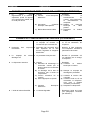
GUASTI
Inconvenienti:
Cause:
Rimedi:
GUASTI ALLE PISTOLE SMACCHIANTI A FREDDO
1. Premendo la leva di comando 1. Il
filtro
dall'ugello fuoriesce solo aria
sull’ingresso
e il liquido arriva ad intervalli.
sporco.
2. La pistola perde.
della
pistola 1. Procedere alla pulizia come
prodotto
è
indicato
nel
paragrafo
"Manutenzione pistole a
freddo”. Se il problema non
si risolve, provvedere a
sostituire il gruppo pompetta,
molle e ago.
2. Le guarnizioni non hanno più 2. Sostituire le guarnizioni e
tenuta oppure le molle si
le molle interne, oppure
sono deformate.
sostituire la pistola.
GUASTI ALLA PISTOLA SMACCHIANTE ARIA / VAPORE (SE
ESISTENTE)
1. Rimedi:
a) Controllare la funzionalità
del
contatto
microinterruttore
ed
eventualmente
sostituirlo.
b) Ripristinare la continuità
b) Interruzione
continuità
elettrica del cavo pistola.
elettrica cavo pistola.
c) Sostituire
bobina
c) Bobina
elettrovalvola
bruciata.
bruciata.
1. Il vapore arriva regolarmente 1. Cause:
alla
macchina
tuttavia,
a) Contatto
premendo il pulsante della
difettoso.
pistola, non esce dall’ugello.
microinterruttore
GUASTI AL COMPRESSORE INCORPORATO (SE ESISTENTE)
1. Perdita
di
pressostato.
aria
2. Insufficiente produzione
aria compressa.
3. La
valvola
scarica l’aria.
di
dal 1. La valvola del pressostato o la 1. Pulire le due valvole, e, se
valvola
di
ritegno
non
necessario, sostituirle.
funzionano correttamente.
di 2. Richiesta eccessiva di aria e/o 2. Pulire filtro aspirazione o
filtro aspirazione della testata
cambiarlo. Controllare la
intasato, segmenti e valvole
resa della testata.
usurate.
sicurezza 3. Pressostato starato.
Pag. 3-8
3. Ritarare il pressostato. Se
non conserva la taratura,
sostituirlo.
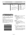
ITALIANO
CAPITOLO 3
4. Interviene il salvamotore.
5. L’olio
della
emulsiona.
testata
ITALIANO
4. Cause:
4. Rimedi:
a) Difficoltà
avviamento
o
a) Controllare la tensione
surriscaldamento dovuto a
elettrica al motore.
bassa tensione ai capi del
motore.
b) Non funziona lo scarico
b) Pulire
la
valvola
di
della testata all’arresto del
scarico del pressostato.
compressore.
c) Eccessiva
tensione
della
c) Controllare la tensione
cinghia.
delle cinghie.
d) Olio non adatto o esaurito.
d) Controllare l'olio e, se
necessario,
sostituirlo.
(vedi punto 2 capitolo
“Manutenzione
settimanale”).
e) Contatti elettrici difettosi
e) Sostituire il salvamotore.
si 5. L’olio si è degradato.
5. Sostituire l’olio della testata
(vedi
paragrafo:
“Manutenzione settimanale”).
GUASTI ALL’ASPIRATORE
1. L’aspiratore non funziona.
1. Cause:
1. Rimedi:
a) La ventola è bloccata da
a) Sbloccare
la
ventola,
corpi estranei.
rimuovendola dai corpi
estranei che la bloccano.
b) Il
microinterruttore
del
b) Sostituire
il
pedale non funziona.
microinterruttore
del
pedale.
c) Il condensatore del motore
c) Sostituire il condensatore
è bruciato.
del motore.
d) Il motore è bruciato.
d) Sostituire il motore.
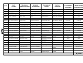
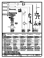
RICHIESTA DEI PEZZI DI
RICAMBIO
I ricambi devono essere ordinati esclusivamente
tramite fax, fornendo codici e descrizioni, al fine di
poter garantire l’invio dei pezzi in tempi brevi.
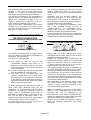
IMPORTANTE:
Per i componenti elettrici con tensione e
frequenza diverse da 220V/230V/240V 50Hz.
(dati da confrontare con quelli della targhetta
dell'articolo guasto) far seguire al codice di
ordinazione la lettera corrispondente alla
tensione desiderata, come da seguente tabella:
Pag. 3-9
A
B
C
D
E
F
G
H
I
L
M
220V/230V 60Hz.
240V 50Hz.
200V 50Hz.
200V 60Hz.
190V 50Hz.
115V 60Hz.
110V 60Hz.
208V 50Hz.
24V 50Hz.
240V 60Hz.
254V 50Hz.
ITALIANO
CAPITOLO 3
Esempio 1:
Occorre una bobina elettrovalvola vapore a
230V/50 Hz.
Dati completi per l’ordine:
• Macchina Modello: Tavolo smacchiante
Tipo..
• Matricola N° 110227
• Codice 04775-bobina elettrovalvola vapore
230V/50 Hz
• N° 1 pezzo
Esempio 2:
Stessa bobina, ma a 254V/50Hz.
Dati completi per l’ordine:
• Macchina Modello: Tavolo smacchiante
Tipo...
• Matricola N° 110228
• Codice
04775/M-bobina
elettrovalvola
vapore 254V/50 Hz
• N° 1 pezzo
N.B.:
1. I particolari che compaiono su questo
manuale senza il numero di codice a fianco,
NON SONO DISPONIBILI a magazzino.
2. La sigla “POS. 90” oppure “POS. 91” etc. che
compare a fianco di alcuni particolari, non ha
nulla a che vedere con il codice di quel
particolare e quindi non deve essere citata
nell’ordinazione dei ricambi.
f)
ITALIANO
Rimontare tutte le pannellature di chiusura
della macchina e rivestirla con un telo per
proteggerla dall'umidità e dalla polvere.
In caso di demolizione agire nel seguente
modo:
a) Scaricare la condensa contenuta nella tazza
filtro aria.
b) Svuotare i serbatoi da ogni residuo di
solvente, raccoglierlo in appositi contenitori e
smaltirlo secondo le norme vigenti.
c) I filtri dell'aria (filtri a carboni attivi, filtri a
paglietta, filtri in nylon) occorre raccoglierli in
appositi contenitori e smaltirli secondo le
norme vigenti.
d) Scaricare l'eventuale serbatoio separatore
condense, assicurandosi che sia privi di
impurità
nocive,
direttamente
nella
fognatura.
e) Rimuovere tutta la componentistica elettrica,
pneumatica, idraulica dai pannelli su cui è
fissata.
f) Raccogliere in appositi contenitori: plastica,
bachelite, ghisa, ferro, rame, ottone, acciaio,
stoffe, gomma etc. e smaltirli secondo le
norme vigenti.
g) Scaricare tutto l’olio contenuto nell’eventuale
compressore
raccoglierlo
in
appositi
contenitori e smaltirlo secondo le norme
vigenti.
ACCANTONAMENTO O
DEMOLIZIONE
In caso di accantonamento per lungo periodo,
occorre scollegare le fonti di alimentazione
idrauliche, elettriche, pneumatiche.
Inoltre occorre:
a) Scaricare la tazza filtro aria compressa.
b) Scaricare
l’eventuale
serbatoio
compressore.
c) Scaricare l’eventuale serbatoio separatore
condense.
d) Pulire i vari tubetti da eventuali tamponi di
calcare.
e) Richiudere tutti i rubinetti a sfera di
alimentazione vapore e di ritorno condensa.
I DATI, LE DESCRIZIONI E LE ILLUSTRAZIONI
CONTENUTI NEL PRESENTE OPUSCOLO
NON SONO IN ALCUN MODO IMPEGNATIVI.
LA FABBRICA SI RISERVA IL DIRITTO DI
APPORTARE, IN QUALSIASI MOMENTO,
TUTTI I CAMBIAMENTI CHE RITERRÀ
OPPORTUNI,
SENZA
L’OBBLIGO
DI
AGGIORNARE IL PRESENTE OPUSCOLO.
Sperando che queste pagine possano
esserVi utili come ci siamo ripromessi,
non ci rimane che augurarVi BUON
LAVORO!
Pag. 3-10
L’UFFICIO TECNICO
ENGLISH
CHA PTER 4
EN GLISH
Capitolo 4 dfdgdhh
INSTALLATION
PACKING
The machine is packed into a special export
cartoon (INDUPACK) fixed on a fumigated
pallet.
TRANSPORT
Upon receipt of the machine packed, you are
kindly requested to immediately report to the
forwarding agent any damage suffered by the
packing during the transport.
In case of damages to the machine as
well,
the
insurance
company
of
the
forwarding agent will be held responsible only if
these
damages
have
been
reported
immediately.
All the installation operations must be
undertaken only by competent personnel
equipped with the necessary protection.
Do not use water jets against the machine for
any reason and avoid sudden movement or
violent blows.
Do not carry the machine by hand, but only
by forklift truck or tackle. It is advisable to
move the machine complete with the packing to
where it is to be installed and then unpack the
machine.
d) Take away from the pallet all the accessories
not fixed or bolted, as they can damage
property, persons or animals when falling
down.
e) Remove the bolts fixing the machine to the
pallet
f) Sling the machine by means of two ropes
(verify that are suitable for the total weight of
the machine), one at the rear and the other
at the front side of machine; then lift it by
means of forklift truck or tackle and place it
where it must be installed, without moving it
by hand.
g) Assemble the stain-removal arm “POS. 87“,
by fitting it in the suitable support placed on
the table “POS. 88“ (see page. 10-5).
h) Assemble the garment holding frame “POS.
89“ (see page. 10-5) and fix it by means
of the three supplied screws onto the
suitable supports placed on the machine
bed.
i) Assemble the lamp, if available, “POS.90”
(see page. 10-5) and fix the relevant support
arm onto the machine by means of the
suitable screws.
j) When installation has been completed,
carefully refit all the panels, protection
devices and the accessories.
Various distances from the walls and other
equipment must be observed during the
installation of the machine in order to ensure
smooth operation and good maintenance.
The equipment does not require any fixing to the
floor.
It is recommended that the equipment should be
installed dead level
COMPRESSED AIR
CONNECTION
UNPACKING AND LAYING OF
THE MACHINE
(FOR MACHINE WITHOUT COMPRESSOR)
(SEE DRAWING PAGE 10-3)
Proceed as following:
a) Remove the indupack by using proper
tools.
b) Remove the plastic protection.
c) Verify that the machine has not suffered
damages during the transport.
The machine needs to be fed with clean
compressed air, without condensation or oil, at a
pressure of 8-10 bars (116-145 psi).
Fit a rilsan or zinc-platted 3/8” GAS pipe to within
1 meter of the machine. Assemble a three-way
ball tap or a sliding tap on its end “POS. 25”.
Page 4-1
ENGLISH
CHA PTER 4
This 3-way ball valve serves to feed the machine
(position 1 = ON = OK) or to turn off the supply
(position 0 = STOP) by discharging the air
remaining in the machine through the silencer.
This ensures that whenever any maintenance is
required, there is the guarantee that there is no
danger from compressed air (jets of air, etc.)
simply by turning the air ball valve to the 0 =
STOP position (or letting the ring nut slip).
Using a rilsan pipe, ∅inside=8mm (≅0,3 inches)
resistant up to a pressure of at least 20 bars
(290 psi), connect the tap to the compressed air
filter “POS. 2” of the machine.
STEAM AND CONDENSATION
RETURN CONNECTION
EN GLISH
The connection between the ball valve and the
machine steam input “POS. 4” can be made
using a copper tube with an internal diameter of
10 mm.
Remember that the machine operates with
steam at a pressure of 4 - 6 bars (58 - 87 psi),
and therefore, if the machine is connected to a
steam generator working at a higher pressure, a
pressure reducer has to be installed.
Connect a 1/2" basin-type condensation, fitted
with a filter (SPIRAX SARCO HM 007 or
JUCKER SA8), to the condensation return
junction drain “POS. 3”. A gate valve must be
fitted after the drain to avoid back pressure.
A ball valve must be fitted on the condensation
return pipe “POS. 68” (1/2" gas pipe) to allow the
isolation of the machine from the plant.
(FOR MACHINES WITH AIR/STEAM SPOTTING
GUN)
ELECTRICAL CONNECTION
(SEE DRAWING PAGE 10-4)
(SEE DRAWING PAGE 10-5)
As illustrated in drawing page 10-4 (figure on the
low), the machine can be directly connected to a
small boiler, without drainage.
As a result, it is imperative that:
a) The height ‘H’ from the floor to the
condensation drainage hole “POS. 3” is
greater than a minimum of 200 mm (8 inches)
from the water level ‘K’ in the boiler, measured
on the same plane.
b) A steel or copper pipe with the recommended
minimum diameter is used (1/2 GAS).
c) The pipes are at a constant angle, with
curves of at least 50 mm (≅2 inches) radius,
that there are no constrictions or narrowing
in the pipes (e.g. tight gate valve connection)
and that the length of each pipe is not greater
than 2.5 metres (=100 inches).
All these precautions are imperative in order to
avoid water being siphoned back into the
equipment. If it is not possible to observe these
precautions, a traditional connection must be
made, using a condensation gate valve, as
illustrated in Drawing page 10-4 (figure on the
top). For this type of connection, take a 1/2"
steel gas pipe from the top of the central steam
conduit and fit it 100 cm from the machine.
Fit a ball valve “POS. 67” to this pipe so as to
isolate the machine from the plant.
Ensure that the mains voltage and phase
correspond with the data given on the machine
specification plate (see page 2-1).
Prepare an electrical line dimensioned as
indicated on the table shown in the drawing on
page 10-5. Insert the cable in the holder “POS.
8”, block it with the collar “POS. 9” and connect
with the clamps to the electrical current.
The electrical supply line must be fitted with an
automatic differential heat safety cut-out switch
30 mA with a mechanical plug and socket block.
The machine as per the rules in force must be
connected to a good earth, or the guarantee will
not be honoured. Before first testing the machine,
check that none of the electrical connectors have
worked loose during transport.
After connection to the electricity supply, check
the rotation direction of the motors (fan). If the
direction is wrong, invert the connection of two
of the three phases supply wires.
N.B.: It is advisable to check the correct rotation
direction of the compressor and of the pump,
otherwise they can be damaged in an
irreparable way. Under these circumstances any
request for replacement of parts under guarantee
cannot be accepted by the manufacturer.
Replace all the panels and protection devices
when the electrical connections have been
completed.
Page 4-2
ENGLISH
CHA PTER 4
EN GLISH
f)
CONNECTION AND USE OF
THE COMPRESSOR
(FOR MACHINE WITH BUILT-IN
COMPRESSOR)
(SEE DRAWING PAGE 10-3)
Unpack the compressor, remove it from its box
and keep the technical and test sheets attached.
Carefully assemble the compressor by bolting it
on the four rubber feet already attached onto the
machine bed.
Connect the compressed air supply pipe from
the fitting of the air coil “POS. 2” to the fitting of
the compressor air outflow “POS. 7”. Switch on
the compressor by pulling the button of the
pressure switch “POS: 78” and press the start-up
button “POS. 79”: in this way the compressor will
load air until a max pressure of 10 bar is reached.
To shut down the compressor and to drain the
compressor head press the button of pressure
switch “POS: 78”
Switch-on the red push-button “POS: 80” of the
magnetotherm switch at the end of the day only.
INSTRUCTION FOR USE OF COMPRESSED
AIR TANK:
To ensure operation of compressed air tanks
under safe conditions, the proper use of same
must be guaranteed.
To this purpose the user should proceed as
follows:
a) Use the tank properly within the rated
pressure and temperature limits stated on
the constructor’s plate and the testing report,
which must be kept with care.
b) Avoid welding on shell and bottom.
c) Assure that the tank is complete with
suitable and adequate safety and control
fittings and replace them with equivalent
ones in case of necessity prior to the
Manufacturer’s consent. In particular, the
safety value must be applied directly to the
tank have a discharge capacity higher than
the air intake and be set and leaded at a
pressure of the tank. The stamp pressure
value on the manometer should be indicated
with a red mark.
d) Avoid storing the tank in badly ventilated
rooms, near heating sources or inflammable
substances.
e) Rule out tank vibrations during operation,
which could cause fatigue failures.
Drain condensation deposits from the tank
dally. An inside corrosion test should be
carried out at quarterly intervals and
intensified if the tanks are used in
conjunction with oil less compressors. The
actual wall thickness of tanks after
corrosion should not be smaller than 3-4
mm.
g) Proceed sensibly and carefully according to
the existing prescriptions.
TAMPERING AND IMPROPER USE OF THE
TANK ARE FORBIDDEN.
The users must comply with the laws on the
operation of pressure equipment in force in the
relative countries.
COLD AND HOT SPOTTING
GUNS ASSEMBLING
(SEE DRAWING PAGE 10-3)
Cold spotting gun assembling “POS. 13”,
“POS. 21”:
a) Assemble the support arm of the guns onto
the support “POS.18” by means of the two
supplied bolts.
b) Connect the short pipes, connected to each
gun, to the relevant fittings “POS.19” of the
compressed air. Connect also the longer
pipes, connected to each gun, to the
cleaner tanks fixed onto the back side of the
table.
Air steam spotting guns assembling:
a) Assemble the small steam-press unit with
the air – steam gun “POS. 33” onto the
support “POS.17” by means of the two
supplied screws.
b) Connect the compressed air supplying pipe
of the air steam gun to the compressed air
inflow fitting “POS.15”.
Compressed air drying gun assembling
(supplied as an alternative to the electric air /
steam spotting gun):
a) Connect the gun “POS. 22” to the
compressed air inflow fitting “POS. 15”.
Page 4-3
ENGLISH
CHA PTER 4
USE OF THE MACHINE
EN GLISH
d) In the case of machine with air/steam
spotting gun, turn on the pistol switch “POS.
14”.
PRELIMINARY CONTROLS
USE OF THE SPOTTING TABLE
AND ARM
(SEE DRAWINGS PAGES 10-3, 4)
a) In the case of machine without built-in
compressor, check that the ball tap for the
compressed air feed “POS. 25” is open and
discharges any condensation deposited in
the compressed air filter bowl by turning the
tap “POS. 26”.
b) In the case of machine with built-in
compressor:
•
Discharges
any
condensation
deposited in the tank, by turning the tap
“POS. 70”.
•
Check that the oil level of the
compressor reaches the central line of
the warning light. If some oil has
leached, add oil SAE 40 (Q8 VERDI
150S, Agip ACER 150 o similar). If oil
exceeds the level-line, the excess will be
blown by the compressor through the
breather and the stuffing box; so it is
advisable not exceed a level.
c) In the case of machine with air/steam
spotting gun, check that the ball valves
fitted on the steam pipe “POS. 67” and on the
condensation return pipe “POS. 68” are open.
At first, when the machine is cold, the steam will
condense rapidly and it is therefore advisable to
wait a few minutes before starting work so that
the condensation can be drained off.
If this is not done, condensation formed will
emerge from the steam pistol, damaging the
garments being processed.
START-UP OF THE MACHINE
(SEE DRAWING PAGE 10-5)
Proceed as following:
a) Turn on the general electrical supply switch.
b) Actuate the switch for the aspirator operation
“POS. 24” or press the pedal “POS. 86”
should a continuous suction be required or
according to the operator’s requirements.
c) In the case of machine with built-in
compressor, lift the pressure switch push
button “POS. 78” and press the heat safety
cut-on switch start button “POS. 79”.
(SEE DRAWING PAGE 10-5)
In order to operate from the spotting arm
“POS.87“ it is necessary to rotate it to the table
centre. In order to operate on the table it is
necessary to rotate the arm clockwise so as to
take it out of the operating position.
USE OF THE SUCTION CABIN
(SEE DRAWING PAGE 13-2)
The suction cabin guarantees the suction of the
chemical product vapours and of the detergents
used for stain removal.
In order to operate the cabin proceed as follows:
a) Release the stop button “POS.51” if it is
blocked, so that the suction device of the
cabin
“POS.52”
will
start
operating
immediately and the use of the cold spotting
guns “POS. 13”, “POS. 21”.will be favoured.
b) Actuate the switch of the lamp “POS.50” and
rotate it so that the light beam illuminates the
operating field.
c) If the electric gun for leather spotting and
cleaning “POS.53” is available connect the
electric plug into the socket “POS.54” so as
to be able to use it.
The air sucked by the cabin and the air sucked
by the spotting table and arm are purified by the
active carbon filter “POS. 55” and expelled free
of any dangerous vapour.
The operating life of this filter depends on the
products used and on the working hours; at any
rate it is recommended to regenerate it at least
once a year.
USING THE AIR-STEAM
SPOTTING GUN
Proceed as follows:
a) Place the part of the item to be cleaned on
the end of the support and press the pedal
“POS. 86” (see page 10-5).
Page 4-4
ENGLISH
CHA PTER 4
b) Press the left button of the gun to release
the steam. For the first few seconds the
steam is mixed with water. Therefore
discharge the pistol for a few seconds until it
is well heated.
c) Distribute the jet of steam onto the stain with
the gun, moving it in rotatory way. Abundant
steaming instantly dissolves water-soluble
stains.
d) If required dry the stained area spray stain
with compressed air by pressing the button
on the right of the gun. Move the gun rapidly
back and forth in a zig-zag motion to
remove the dampness in the stain with the
air. The strong, concentrated vacuum
allows rapid drying.
TIPS ON STAIN REMOVAL
(SEE DRAWINGS PAGE 10-3)
Follow the warnings printed on the containers of
cleaning products.
It is a fact that the best results can be achieved
only by practical experience through use; anyway
the following instructions can be of help:
a) The spotting guns “POS. 13” and “POS. 22”
must be used very close to the cloth (at
about ½ cm) to get the maximum penetration
of water/air mixture into the fibre; this action
should remove any foreign matter from the
cloth. Spot removing depends to the
mechanical
action
of
the
water/air
combination. Therefore water should be
used sparingly , which also helps the drying.
The lever of the gun should be depressed
gradually to obtain a spot-on water/air
combination set to the stain, rotating the gun
action so that removal may be easier.
b) For all difficult or old spots, a neutral soap
should be used to help with the spot removal.
c) For particular stain whose nature is identified
(ex. blood and paint spots) use the specified
products supplied by the qualified suppliers.
d) The drying air gun “POS. 22” or “POS. 33”
should always be brought into contact with
the cloth to allow the maximum penetration
of air without losses.
e) If the air/steam gun unit “POS. 33” is
available, a steam jet can be used onto the
fabric to which the stain remover has been
applied, so as to accelerate its action. By
means of this gun it is also possible to
remove light stains
EN GLISH
SHUTTING DOWN OF THE
MACHINE
(SEE DRAWINGS PAGES 10-3, 4)
a) In the case of machine without
compressor, close the ball tap assembled
on the air compression line “POS. 25”.
b) In the case of machine with air/steam
spotting gun, close the two gate valves
“POS. 67” and “POS: 68” fitted to the steam
line and the condensation return. Turn off
the pistol switch “POS. 14” (see page 10-5).
c) If the machine has an integrated
compressor, turn the compressor off by
pressing the pressure switch “POS. 78”, the
automatic discharge of the compressor
head is performed
NOTE: Actuate the red button “POS. 80” of
the magnet-thermal switch only at the end of
each working day.
d) Disconnect the switch operating the suction
device “POS. 24” (see page 10-5), then the
main switch of the power supply line.
MAINTENANCE
The following instructions are of prime importance
in keeping the machine perfectly efficient,
ensuring its maximum performance, and avoiding
expensive down time.
The first part of this section is divided into
chapters according to periodic maintenance
schedules.
N.B.: The frequency indicated (weekly, monthly,
etc.) is indicative and refers to a machine that
operates under ‘normal’ conditions.
The individual customer has to decide on the
exact frequency of the maintenance work on the
basis of the following guide lines:
• the amount of work done by the machine;
• the amount of dust in the air;
• other local working conditions.
All the maintenance operations must be
undertaken with the machine completely switched
off, and in particular:
a) The general electrical power switch must be
off and the plug removed from the socket.
Page 4-5
ENGLISH
CHA PTER 4
EN GLISH
b) For machine without compressor, the
compressed air ball valve “POS. 25” (see
page 10-3) must be closed and discharged
any
condensation
deposited
in
the
compressed air filter bowl by turning the tap
“POS. 26” (see page 10-3).
c) For machines with built-in compressor, all
the compressed air present in the machine
must be discharged by turning the tap “POS.
70” (see page 10-4).
d) For machine with air/steam spotting gun,
close the two gate valves “POS. 67” and
“POS. 68” fitted to the steam line and the
condensation return (see page 10-4).
e) The hot parts of the machine must be left to
cool (internal pipes, valves, the boiler, if fitted,
etc.) in order to avoid burns.
c) For machine with compressor, check the oil
level and top up if necessary, always using
lubricants similar to that one already in use
(Agip ACER 150, Q8 VERDI 150). We
recommend to replace the oil after 100
running in hours and, after that, every 300
operating hours.
d) Clean the air filter of the head every 100
hours and replace it every 6 months.
e) Discharge the condensation from the cooling
coil by opening the condensation discharge
valve “POS. 40” (see page 10-3).
Only by observing all these precautions, and the
particular conditions relating to the individual
maintenance jobs, is it possible to carry out
maintenance work on the machine with complete
safety. Remember ‘you can never by too
careful’!
In order to make potential dangers more evident,
adhesive symbols have been applied to critical
parts of the machine: the meaning of these
symbols is explained in detail in the red section
at the beginning of this manual (Prescription,
danger and indication signals).
a)
N.B. In any case, the maintenance work must
be undertaken only by competent personnel
who can take personal responsibility for their
own safety and that of other persons,
animals and property. The law, and in
particular the latest EU Directives, severely
punish the owner of a machine who allows
maintenance work to be carried out by nonqualified personnel
d)
SIX MONTHLY / YEARLY
MAINTENANCE
b)
c)
e)
f)
WEEKLY MAINTENANCE
a) Check the air compressor filter, empty the
water deposited in the filter bowl using the
discharge tap.
b) Discharge the condensation from the
compressor tank by opening the condensation
discharge valve “POS. 70” (see page 10-4)
Page 4-6
An efficient vacuum is essential for a good
spotting results. Eventual decrease of
vacuum caused by blocked screen will
effect the spotting results.
Therefore it is advisable every time a suction
decrease is noted, to disassemble the
screen frame “POS. 27” and “POS. 28” (see
page 10-2) and clean them from eventual
impurities.
Clean the suction pipe of the table of the arm
and the condensation separator tank “POS.
34” (see page 10-4)by disassembling the
separator.
Check the condition of all the labels and
plates on the machine (warnings and
instructions). If they are in poor condition,
replace them.
Only for machines connected to a steam
source, clean the filter located onto the
condense return piping.
Maintenance of the cold spotting guns
and of the liquid basins (see drawing page
13-4): clean the filters every time you note
decrease in the flow of the chemical product.
Proceed as follows:
•
Close with the thumb the air/cleaner
mixture outlet nozzle.
•
Press the gun lever: at first air will be
collected, which, being prevented from
flowing out of the nozzle, will remove
clogging from the filters.
ENGLISH
CHA PTER 4
EN GLISH
BREAKDOWNS
Problem:
Causes:
Action:
BREAKDOWNS TO COLD SPOTTING GUNS
1. Pressing the control lever, air 1. Filter is dirty.
is discharged only or the fluid
arrives at intervals.
2. The gun leaks.
1. Clean as indicated in the
paragraph
“Cold
gun
Maintenance”.
Disassemble the knob of
the gun so as to access
the disassembly of the air
fitting and replace the
pump, spring and needle
group.
2. The gaskets are no longer 2. Replace the gun.
tight or the springs are
deformed.
BREAKDOWNS TO THE STEAM/AIR SPOTTING GUN
1. Steam
available
to
the 1. Causes:
1. Action:
machine, but pushing the gun
a) Micro-switch
contact
a) Check the micro-switch
button no steam available
defective.
contact and if necessary
from nozzle.
replace it.
b) Break of the gun cable
b) Check the continuity and
continuity.
repair accordingly.
c) Solenoid valve coil burned.
c) Replace burned coil.
BREAKDOWNS ON THE BUILT-IN COMPRESSOR (IF FITTED)
1. Air leak in the manostat.
2. Insufficient
production
compressed air.
1. The manostat valve or gate 1. Clean the two valves and if
valve is malfunctioning.
necessary replace them.
of 2. Excessive air demand and/or 2. Clean
or
replace
the head exhaust filter is
exhaust filter. Check
blocked, worn valves and air
head performance.
feed tubes.
Page 4-7
the
the
ENGLISH
CHA PTER 4
EN GLISH
3. The safety valve discharges 3. Manostat not calibrated.
air.
or
low
4. Action:
a) Check
the
electricity
supply to the motor.
not
the
b) Clean
the
manostat
discharge valve.
d) Unsuitable
oil,
or
oil
exhausted.
e) Defective electrical contacts.
c) Check the tension of the
belts.
d) Check the oil and replace
it if necessary.
e) Replace the head oil.
4. The motor safety cut-out is 4. Causes:
triggered.
a) Difficult
start
up
overheating due to
voltage to the motor.
b) Head
discharge
functioning
when
compressor is stopped.
c) Belts too tight.
5. The head oil is emulsified.
3. Re-calibrate the manostat.
If it does not remain
calibrated, replace it.
5. The oil is exhausted.
5. Replace the head oil.
EXHAUST FAN BREAKDOWNS
1. The exhaust fan does not 1. Causes:
1. Solutions:
work.
a) The fan is blocked by foreign
a) Unblock
the
fan
by
objects.
removing
the
foreign
bodies that are blocking
it.
b) The micro-switch on the
b) Change the micro-switch
pedal does not work.
on the pedal.
c) The motor condenser is
c) Change
the
motor
burned out.
condenser.
d) The motor is burned out.
d) Change the motor.
ORDERING SPARE PARTS
The spare parts must be ordered only by fax with
codes and descriptions in order to ensure the
rapid despatch of the parts.
IMPORTANT
For electrical components other than for
220V/230V/240V 50 Hz supply (check on the
specification plate of the defective part), add to
the order code the letter corresponding to the
rating required as given in the following table:
Page 4-8
A
B
C
D
E
F
G
H
I
L
M
220V/230V 60Hz.
240V 50Hz.
200V 50Hz.
200V 60Hz.
190V 50Hz.
115V 60Hz.
110V 60Hz.
208V 50Hz.
24V 50Hz.
240V 60Hz.
254V 50Hz.
ENGLISH
CHA PTER 4
Example 1:
An 230V 50 Hz coil steam solenoid valve is
required.
Complete order information:
• Machine model: Spotting Table Type .....
• Registration No. 110227
• Code No. 04775 - coil steam solenoid valve
230V/50 Hz
• 1 piece
Example 2:
The same coil, but 254V, 50 Hz.
Complete order information:
• Machine model: Spotting Table Type .....
• Registration No. 110228
• Code No. 04775/M coil steam solenoid
valve 254V/50 Hz
• 1 piece
N.B.
1. The parts that appear in this manual without
an accompanying code number ARE NOT
AVAILABLE from stock.
2. The codes “POS. 90” or “POS. 91” etc. that
appear next to some parts have nothing to do
with the spare part code for these parts, and
should not therefore be quoted in orders for
spare parts.
STORAGE OR DEMOLITION
EN GLISH
In case of demolition of the machine, proceed as
follows:
a) Remove the condense contained in the air
filter pan.
b) Empty the tanks of any residual solvent,
collect it into the suitable containers and
discard it in compliance with the regulations in
force.
c) The air filters (active carbon filters, mesh wire
filters, nylon filters) should be collected into
the suitable containers and discarded in
compliance with the regulations in force.
d) Empty the condense separator tank, if
available, making sure that it is free of any
dangerous material, and discard it directly into
the sewage.
e) Remove all the electric, pneumatic and
hydraulics components from the panels where
they are fixed.
f) Collect into proper container the following
parts: plastic, bakelite, cast iron, iron, copper,
brass, steel, fabrics, rubber etc. and take
them away according to the rules in force.
g) Discharge all the oil contained in the
compressor, if any, collect it into the suitable
containers and discard it in compliance with
the regulations in force.
In case of a long period storage, it is necessary to
disconnect the hydraulics, electric and pneumatic
feeding sources.
THE SPECIFICATIONS, THE DESCRIPTIONS
AND THE ILLUSTRATIONS CONTAINED IN
THIS BOOKLET ARE NOT IN ANY WAY
BINDING. DUE TO CONTINUOUS RESEARCH
AND DEVELOPMENT TO IMPROVE OUR
PRODUCTS, THE MANUFACTURER MAY
ALTER SPECIFICATIONS WITHOUT PREVIOUS
NOTICE.
a)
b)
c)
d)
e)
We trust that these few pages will be of
use to you and wish you ‘Buon lavoro!’ as
we say in Italy — May your work go well!
Drain the air inside the air filter cup.
Drain the compressor tank (if existing).
Drain the condensation tank (if existing).
Clean all connections removing any scaling.
Turn off all the steam feeding valves and the
of condensation return valve.
Carefully refit all the panels of the machine and
cover it with a cloth to shelter from the humidity.
Page 4-9
Technical Office
FRANCAIS
CHAPITRE 5
FRANCAIS
Capitolo 5 .
INSTALLATION
EMBALLAGE
La machine est emballée dans un carton export
spécial (INDUPACK) fixé sur une palette fumiguée:
TRANSPORT
À la livraison de la machine emballée, nous Vous
prions de notifier immédiatement par écrit au
transporteur les dommages éventuels subis par
l’emballage pendant le transport.
Dans le cas où ces dommages auraient intéressé
la machine, en effet, l’assurance du courrier
répondra seulement si les dommages présumés
ont été signalés immédiatement.
Toutes opérations d’installation doivent être
exécutées par du personnel qualifié, muni des
protections nécessaires (gants, protections contre
les accidents, etc.). N’utiliser pas de jets d’eau
contre la machine pour aucune raison, et éviter les
mouvements soudains ou les chocs violents.
La machine ne doit être jamais transportée à bras,
mais avec l’aide de chariots élévateurs et palans
mécaniques.
Transporter la machine encore complètement
emballée jusqu’à l’endroit le plus proche au point
d’installation et procéder au déballage.
DEBALLAGE ET MISE EN PLACE
DE LA MACHINE
d) Enlever du fond tous les accessoires qui ne
sont pas fixés ou boulonnés sur la palette,
puisque quand la machine est déplacée, ils
peuvent tomber et endommager les choses,
les personnes ou les animaux.
e) Enlever les boulons qui fixent les pieds de la
machine sur le fond.
f) Elinguer la machine avec deux cordes
(vérifier qu’elles sont appropriées pour le
poids total de la machine, qui peut être relevé
de la plaquette données techniques), l’une du
côté postérieur et l’autre du côté antérieur de
la machine; enfin, à l’aide d’un chariot
élévateur ou d’un palan mécanique, soulever
la machine et la positionner dans l’endroit
destiné à l’installation sans plus la déplacer à
bras.
g) Monter la forme bras détachant “POS. 87“, en
l’insérant dans le support positionné sur la
table “POS. 88“ (voir à la page 10-5).
h) Monter le châssis porte-vêtements “POS. 89“
(voir page 10-5) et le fixer, avec les trois vis
fournies, dans les supports appropriés
positionnés sur le bâti de la machine.
i) Monter l’éventuelle lampe “POS.90” (voir
page 10-5) et fixer le bras relatif au support
sur la machine au moyen des vis.
j) À
la
fin
de
l'installation,
remonter
soigneusement
les
panneaux
et
les
protections de la machine.
Il faut observer quelques mesures de distance
des parois et des autres machines, afin
d’assurer des opérations plus fluides et un
entretien parfait.
La machine ne nécessite d’aucun ancrage au sol.
Nous Vous recommandons de la poser sur une
surface parfaitement plane.
BRANCHEMENT AIR COMPRIME
(POUR MACHINES SANS COMPRESSEUR)
(VOIR DESSIN A LA PAGE 10-3)
Procéder de la manière suivante:
a) Enlever l'indupack en utilisant des outils
mécaniques appropriés.
b) Enlever la couverture en polyéthylène (PE) qui
enveloppe la machine.
c) Vérifier que la machine n’a subi aucun
dommage pendant le transport.
La machine doit être alimentée avec de l’air
comprimé propre, sans condensat ni huiles,
ayant une pression de 8-10 bars (116-145 psi).
Disposer un tuyau en fer zingué ou Rilsan de
3/8”GAS jusqu’à 1 mètre de la machine.
À son extrémité, monter un robinet a sphère à 3
voies, ou à chariot “POS. 25”.
Page 5-1
FRANCAIS
CHAPITRE 5
Ce robinet à 3 voies permet d’alimenter la
machine (position 1=ON=OK), ou de la désactiver
(position 0=OFF=STOP) en déchargeant l’air qui
reste dans la machine par le silencieux. De cette
manière, dans le cas où il faudrait exécuter
n’importe quelle opération d’entretien sur la
machine, Vous aurez la garantie qu’ il n’y a plus
aucun danger de nature pneumatique (jets d’air,
mouvements des pistons, etc.) lors que le robinet
est tourné en position 0=OFF=STOP (ou si la frette
a été glissée).
Au moyen d’un tuyau en Rilsan de ∅ interne =
8mm (≅ 0,3 pouces) résistant au moins à 20 bars
(290 psi) de pression, brancher le robinet au
raccord alimentation air comprimé “POS. 2”.
BRANCHEMENT VAPEUR ET
RETOUR CONDENSAT
(POUR MACHINES AVEC GROUPE PISTOLET
AIR/VAPEUR)
FRANCAIS
À l’extrémité de ce tuyau, monter un robinet à
sphère “POS. 67”, afin d’exclure la machine du
reste de l’installation.
Le branchement du robinet à sphère au raccord
entrée vapeur “POS. 4” peut être réalisé avec un
tuyau en cuivre ayant un diamètre interne de 10
mm, ou avec un tuyau flexible approprié pour la
vapeur.
Nous Vous rappelons que la machine fonctionne
avec de la vapeur à la pression de 4-6 bars (6090 psis) et pourtant, si la machine est branchée à
un générateur de vapeur qui fonctionne à une
pression plus élevée, il faut installer un réducteur
de pression.
Brancher au raccord retour condensat “POS. 3”
une soupape décharge condensat de 1/2" GAS à
“ seau inversé ” avec filtre (SPIRAX SARCO HM
007 ou JUCKER SA8).
En aval de la décharge il faut monter une
soupape de retenue à clapet afin d’éviter les
contre-pressions sur la soupape de décharge.
Il est indispensable de monter un robinet à
sphère “POS. 68” sur les conduits de retour
condensat (tuyau de 1/2" GAS) pour avoir la
possibilité d’exclure la machine du reste de
l’installation.
(VOIR DESSIN A LA PAGE 10-4)
Comme illustré dans le dessin à la page 10-4
(figure au bas de la page), on peut brancher la
machine à une petite chaudière de manière
directe, c’est à dire sans décharge.
Il est en tout cas nécessaire que:
BRANCHEMENT ELECTRIQUE
a) La cote du sol “H” du trou de décharge
condensat “POS. 3” soit supérieure d’au
moins 200 mm (8 pouces) au niveau d’eau “K”
dans la chaudière, mesuré sur le même plan.
b) Il soit utilisé un tuyau en fer ou cuivre, au
diamètre minimum conseillé (1/2” GAS).
c) Les tuyaux aient une pente constante, les
rayons des coudes soient d’au moins 50 mm.
(≅ 2 pouces), il n’y ait aucun étranglement
dans les conduits et la longueur de chaque
tuyau ne soit pas supérieure à 2,5 mètres
(100 pouces).
(VOIR DESSIN A LA PAGE 10-5)
Toutes ces précautions sont indispensables pour
empêcher les remous d’eau et, s’elles ne sont
pas réalisables, il faut effectuer un branchement
traditionnel, c’est à dire avec une décharge du
condensat, comme illustré dans le dessin à la
page 10-4 (figure en haut de la page).
Pour ce dernier type de branchement, dériver de
la partie haute du conduit central vapeur un tuyau
en fer de 1/2" GAS et le poser jusqu’à 100 cm de
la machine.
S’assurer que la tension et la fréquence de ligne
correspondent à celles indiquées sur la plaquette
données techniques de la machine (voir à la page
2-1).
Disposer une ligne électrique dimensionnée
comme indiqué par le tableau illustré dans le
dessin à la page 10-5.
La ligne du courant devra être équipée avec un
interrupteur
automatique
magnétothermique
différentiel de 30 mA, avec prise et fiche à
interbloc mécanique.
Il est obligatoire, sous peine de déchéance de la
garantie, de brancher la machine à une bonne
mise à la terre selon les normes en vigueur.
Contrôler, avant de l’essai initial, que les bornes de
tous les composants électriques ne sont pas
desserrés après le transport.
Après la connexion, vérifier le sens de rotation du
compresseur (seulement pour machine avec
compresseur) et, dans le cas qu’il soit incorrect,
invertir deux des trois phases d’entrée.
Page 5-2
FRANCAIS
CHAPITRE 5
N.B.: Il est indispensable de s’assurer du sens de
rotation correct du compresseur, puisque s’il
tourne dans un sens incorrect, il s’endommage
irréparablement. Dans ces cas là, le producteur ne
peut pas accepter les demandes de remplacement
en garantie.
Remonter tous les panneaux et les protections de
la machine.
MONTAGE ET USAGE DU
COMPRESSEUR
(POUR MACHINES AVEC COMPRESSEUR)
(VOIR DESSIN A LA PAGE 10-3)
Déballer le compresseur de la boite où il est
contenu et conserver avec soin les fiches
techniques et d’essai jointes.
Monter soigneusement le compresseur en le
boulonnant sur les quatre pieds en caoutchouc
déjà fixés sur le bâti de la machine.
Brancher le tube d’alimentation de l’air comprimé
du raccord du serpentin air “POS. 2” au raccord
sortie air du compresseur “POS. 7”.
Pour démarrer le compresseur, soulever le
poussoir du pressostat “POS. 78” “POS. 79”: le
compresseur chargera de l’air jusqu’à atteindre
une pression maximale d’environ 10 bars.
Pour arrêter le compresseur, appuyer sur le
poussoir du pressostat “POS.78” ; cette opération
obtient aussi la décharge automatique de la tête
du compresseur.
Utiliser le poussoir rouge “POS.80” de
l’interrupteur magnétothermique seulement à la
fin de la journée.
c) S’assurer que le réservoir soit toujours
équipé avec des dispositifs de sécurité
suffisants et efficients et pourvoir, en cas de
nécessité, à leur remplacement avec des
autres
ayants
des
caractéristiques
équivalentes. En particulier, la soupape de
sûreté doit être appliquée directement sur le
réservoir
sans
aucune
possibilité
d’interposition; elle doit avoir une capacité de
décharge supérieure à la quantité d’air
disponible dans le réservoir et doit être tarée
et plombée à la pression de marque du
réservoir. Sur le manomètre, la pression de
marque doit être indiquée par un signe rouge.
d) Eviter attentivement de placer le réservoir
dans des endroits pas suffisamment airés,
dans des zones exposées aux sources de
chaleur et en proximité de substances
inflammables.
e) Eviter que le réservoir soit assujetti à des
vibrations pendant l’usage, qui peuvent
générer des ruptures causées par la fatigue.
f) Décharger tous les jours le condensat qui se
produit à l'intérieur du réservoir et vérifier
tous les trois mois la présence d’éventuelles
corrosions internes dans le réservoir.
Cependant, l’épaisseur effective du réservoir
après la corrosion ne devra pas être
inférieure à 3-4 mm.
g) Agir en tout cas avec prudence et pondération
par rapport aux cas prévus.
IL
EST
ABSOLUMENT
INTERDIT
D’INTERVENIR SUR LE RÉSERVOIR ET DE
L’UTILISER IMPROPREMENT.
Nous rappelons à l’utilisateur qu’il est en tout cas
obligé à respecter les lois sur l'usage des appareils
à pression en vigueur dans le Pays d’utilisation.
NOTES POUR L’USAGE DU RÉSERVOIR DU
COMPRESSEUR:
L’usage correct du réservoir à pression de l’air
comprimé c’est la chose indispensable pour
garantir la sécurité; dans ce but, l'utilisateur doit
observer, entre les autres, les renseignements
suivants:
a) Utiliser correctement le réservoir dans les
limites de pression et de température de
projet qui sont mentionnées sur la plaquette
du producteur et sur le document d’essai, qui
doit être conservé avec soin.
b) Eviter d’effectuer des soudures sur la jupe
cylindrique et sur le fond.
FRANCAIS
MONTAGE PISTOLETS
DETACHANTS A FROID ET A
CHAUD
(VOIR DESSIN A LA PAGE 10-3)
Montage pistolets détachants à froid “POS.
13”, “POS. 21”:
a) Monter le bras de soutien des pistolets sur le
support “POS.18” en utilisant les deux
boulons fournis.
Page 5-3
FRANCAIS
CHAPITRE 5
b) Brancher les tubes courts, connectés à
chaque pistolet, dans les raccords relatifs
“POS.19” de l’air comprimé. Brancher aussi
les tubes plus longs, connectés à chaque
pistolet, aux réservoirs pour produits
détachants fixés sur la partie postérieure de
la table.
Montage pistolets détachants air/vapeur:
a) Monter le petit groupe fer à vapeur avec
pistolet air/vapeur “POS. 33” sur le support
“POS.17” en utilisant les deux vis fournies.
b) Brancher le tube d’alimentation de l’air
comprimé du petit groupe pistolet air/vapeur
“POS. 91” au raccord entrée air comprimé
“POS.15”.
Montage pistolet séchoir à air comprimé
(fourni en alternative au pistolet électrique
détachant à air/vapeur):
a) Brancher le pistolet “POS. 22” au raccord
entrée air comprimé “POS. 15”.
USAGE DE LA MACHINE
VERIFICATIONS PRELIMINAIRES
Au début, quand la machine est froide, la vapeur
qui arrive se condensera rapidement; nous
conseillons pourtant d’atteindre quelques minutes
avant de commencer les opérations, de manière
que tout le condensat formé puisse se décharger.
Si Vous manquez d’observer cette norme, le
condensat abondant qui se forme sortira du
pistolet vapeur et endommagera le vêtement.
DEMARRAGE MACHINE
(VOIR DESSIN A LA PAGE 10-5)
Procéder dans la manière suivante:
a) Allumer l’interrupteur général prévu sur la
ligne électrique d’alimentation.
b) Insérer l’interrupteur démarrage aspirateur
“POS. 24” ou appuyer sur la pédale “POS.
86“, si Vous désirez une aspiration continue
ou à discrétion de l’opérateur.
c) Dans le cas de machine avec compresseur
incorporé, appuyer sur le poussoir de marche
de l’interrupteur magnétothermique “POS. 79”
et soulever le poussoir du pressostat “POS.
78”.
d) Dans le cas de machine avec groupe
pistolet air/vapeur, allumer l’interrupteur
“POS. 14“ pour activer le pistolet.
(VOIR DESSINS AUX PAGES 10-3, 4)
a) Dans le cas de machine sans compresseur
incorporé, contrôler que le robinet à sphère
d’alimentation air comprimé “POS. 25” est
ouvert et décharger l’éventuel condensat
déposé dans le godet filtre air comprimé, en
agissant sur le robinet relatif “POS. 26”.
b) Dans le cas de machine avec compresseur
incorporé:
•
Décharger le condensat formé dans le
réservoir par le robinet “POS. 70”.
•
Vérifier que le niveau de l’huile du
monobloc compresseur arrive à la moitié
de la lampe témoin appropriée. Au cas où
il manque de l’huile, remplir le niveau
avec de l’huile SAE 40 (Q8 VERDI 150S,
Agip ACER 150 ou similaires). Si l’huile
introduit excède le niveau maximum,
l’excès sera expulsé du compresseur par
les évents; nous conseillons pourtant de
ne pas dépasser ce niveau.
c) Dans le cas de machine avec groupe
pistolet air/vapeur, contrôler que les
robinets à sphère montés sur les conduits
d’alimentation vapeur “POS. 67” et retour
condensat “POS. 68” sont ouverts.
FRANCAIS
USAGE TABLE ET BRAS
DETACHANT
(VOIR DESSIN A LA PAGE 10-5)
Pour travailler avec le bras détachant “POS.87“, il
faut le tourner au centre de la table.
Pour travailler sur la table, il faut tourner le bras
dans le sens des aiguilles d’une montre pour le
porter au dehors de la position de travail.
USAGE CABINE ASPIRANTE
(VOIR DESSIN A LA PAGE 13-2)
La cabine aspirante garantit l’aspiration des
vapeurs des produits chimiques et des savons
détergents usés pour le détachage.
Pour démarrer la cabine, il faut:
a) Débloquer le poussoir de stop “POS.51”
dans le cas où il soit bloquée; de cette façon
il s’actionnera immédiatement l’aspirateur de
la cabine “POS.52” et il se facilitera l’usage
des pistolets détachants à froid “POS. 13”,
“POS. 21”.
Page 5-4
FRANCAIS
CHAPITRE 5
b) Allumer l’interrupteur de la lampe “POS.50” et
la tourner jusqu’à illuminer la zone de
travail.
c) Dans le cas où il y à le pistolet électrique pour
détachage “POS.53”, brancher sa fiche dans
la prise “POS.54” pour son utilisation.
a)
L’air aspiré de la cabine, de la table et du bras
détachant est purifié par le filtre à charbons actifs
“POS. 55” et expulsé sans vapeurs nocives.
La durée de ce filtre est liée aux produits utilisés
et aux heures de travail; nous recommandons en
tout cas de le régénérer au moins une fois par
année.
USAGE PISTOLET DETACHANT
AIR-VAPEUR
b)
Procéder comme ensuite:
a) Positionner la partie détachante sur la pointe
de la table ou de la forme pour bras et
appuyer sur la pédale d’aspiration “POS. 86”
(voir page 10-5).
b) Appuyer sur le poussoir gauche du pistolet
pour obtenir la sortie de la vapeur. Pour les
premières
secondes
la
vapeur
sera
mélangée avec de l’eau ; il est pourtant
nécessaire de décharger le pistolet pour
quelques secondes, jusqu’à quand il sera
bien chauffé.
c) Diriger le jet de vapeur sur le tissu sur lequel
le produit à détacher a été appliqué, avec un
mouvement
rotatif
du
pistolet.
Une
vaporisation
abondante
dissolve
instantanément les taches solubles en eau.
d) Pour sécher la zone détachée, appuyer sur
l’éventuel poussoir droite du pistolet, et
obtenir la sortie de l’air comprimé. Déplacer
rapidement le pistolet avec un mouvement à
zigzag, de manière que l’humidité soit
expulsée avec l’air. La forte aspiration
concentrée facilite un séchage rapide.
CONSEILS UTILS POUR LE
DETACHAGE
c)
d)
e)
FRANCAIS
Les pistolets détachants “POS. 13” et “POS.
21” doivent agir à une distance d’environ ½
cm du tissu. A cette distance, l’on obtient
une pénétration maximale du mélange
air-eau, qui est projeté sur la partie à
détacher avec une pression de 8-10 bars
(116-145 psi), et donc un impact capable
d’enlever mécaniquement chaque particule
étrangère du tissu. Du moment que le
détachage est obtenu en grande partie par
effet de l'action mécanique du mélange aireau, nous Vous conseillons d’user la plus
petite quantité d’eau possible; ceci facilite
aussi le séchage successif. Pour obtenir le
maximum d’action mécanique avec l’usage
de la plus petite quantité de liquide possible,
il faut agir graduellement sur le levier du
pistolet jusqu’à obtenir une sortie du mélange
air-eau des dimensions d’une aiguille.
Pour des taches particulièrement résistantes
ou très vielles, il est indispensable d’utiliser
un bon savon neutre. Le savon répandu sur
la tache en facilite la dissolution et la
solubilisation.
Pour des taches particulières, dont la nature
est identifiée (par exemple, taches de bâton,
sang, peinture, gras etc.), utiliser les produits
spécifiques fournis par les producteurs
spécialisés.
Pour les opérations de séchage du tissu, les
pistolets séchoirs “POS. 22” ou “POS. 33”
doivent être empoignés de manière que leur
bec soit perpendiculaire et appuyé sur le
tissu, pour faciliter la pénétration maximale
sans dispersions inutiles, il faut actionner
simultanément l’aspiration.
Dans le cas où le groupe pistolet air/vapeur
“POS. 33” est fourni, on peut utiliser un jet de
vapeur sur le tissu sur lequel le produit
détachant a été appliqué, de manière d’en
accélérer l’action. Par ce pistolet on peut
aussi éliminer les taches les plus légères.
OPERATIONS A
EFFECTUER A LA FIN DU
TRAVAIL
(VOIR DESSINS AUX PAGES 10-3 ET 10-4)
(VOIR DESSINS A LA PAGE 10-3)
Observer les renseignements mentionnés sur
les flacons des produits pour le détachage.
Attendu que les meilleurs résultats peuvent être
obtenus avec l’expérience que l’on acquière avec
l’usage, les conseils suivants peuvent accélérer
les temps d’apprentissage.
a) Dans le cas de machine sans compresseur
incorporé, serrer le robinet à sphère monté
sur le réseau d’alimentation air comprimé
“POS. 25”.
b) Dans le cas de machine avec groupe
pistolet air/vapeur, serrer les robinets à
sphère montés sur les conduits d’alimentation
vapeur “POS. 67” et retour condensat “POS.
68” et débrancher l’interrupteur d’allumage du
pistolet “POS.14” (voir page 10-5).
Page 5-5
FRANCAIS
CHAPITRE 5
c) Dans le cas de machine avec compresseur
incorporé, arrêter le compresseur en
appuyant sur le poussoir du pressostat “POS.
78”, de manière à obtenir la décharge
automatique de la tête du compresseur.
N.B.: Utiliser le poussoir rouge “POS. 80” de
l’interrupteur magnétothermique seulement à
la fin de la journée.
d) Dans le cas de machine avec cabine
aspirante, arrêter l’interrupteur de la lampe
“POS. 50” et bloquer le bouton de stop “POS.
51”.
e) Débrancher l’interrupteur de démarrage de
l’aspirateur “POS. 24” (voir à la page 10-5), et
enfin l’interrupteur général prévu sur la ligne
d’alimentation.
ENTRETIEN
Les renseignements suivants sont d’importance
vitale pour avoir une machine toujours
parfaitement efficiente, qui Vous donnera le
maximum de performance et Vous évitera des
arrêts de production très dispendieux.
La première partie de cette section est divisée
en chapitres, selon une majeure ou mineure
fréquence de chaque opération d’entretien.
N.B.: La fréquence que nous avons indiquée (par
semaine, mensuelle, etc.) est indicative et elle
concerne une machine qui travaille en conditions
“normales”. Vous pouvez établir vous-mêmes la
cadence exacte des opérations d’entretien, en
fonction des paramètres suivants:
• Quantité du travail exécuté par la machine;
• Poudres dans l’air;
• Autres conditions particulières.
Toutes opérations d’entretien doivent être
exécutées en s’assurant que la machine est
complètement arrêtée, et en particulier:
a) L’interrupteur général prévu sur la ligne
électrique doit être éteint et la fiche doit être
débranchée de la prise.
b) Pour les machines sans compresseur, il
faut serrer le robinet d’alimentation air
comprimé “POS.25“ (voir à la page 10-3) et
décharger l’air qui reste dans la machine en
agissant sur le décharge du filtre “POS. 26”
(voir à la page 10-3).
FRANCAIS
c) Pour les machines avec compresseur
incorporé, il faut décharger tout l’air
comprimé accumulé dans la machine en
agissant sur le robinet de décharge “POS. 70”
(voir à la page 10-4).
d) Pour les machines avec groupe pistolet
air/vapeur, il faut serrer les robinets à sphère
d’alimentation vapeur “POS. 67” et de retour
condensat “POS. 68” (voir à la page 10-4).
e) Il faut laisser refroidir les parties chaudes de
la machine (tuyaux internes, soupapes,
chaudière éventuelle, etc.) afin de ne pas se
brûler.
Seulement si Vous observez toutes ces
précautions, et les autres suggérées par des
conditions contingentes particulières, on peut
exécuter les opérations d’entretien sur la machine
dans une sécurité absolue, et en se rappelant que
“on n’est jamais trop prudent”.
Pour mieux mettre en évidence ces dangers,
nous avons placé des etiquettes autocollantes
sur les points critiques de la machine, dont la
signification est expliquée en détail à la page
rouge au début de ce manuel (“Signaux de
prescription, danger et indication”).
N.B.: En tout cas, les entretiens doivent être
effectués exclusivement par du personnel
compétent, qui répond personnellement de sa
propre intégrité et de celle des autres
personnes/animaux/choses
éventuellement
intéressées. La loi, et notamment les dernières
directives de la CEE, punit sévèrement le
propriétaire de la machine s’il fait exécuter des
entretiens par du personnel non compétent.
ENTRETIEN PAR SEMAINE
a) Contrôler le filtre air comprimé, décharger
l’eau, nettoyer le godet filtre.
b) En utilisant le robinet approprié “POS. 70”
(voir à la page 10-4), décharger le condensat
qui se forme à l’intérieur de l’éventuel
réservoir compresseur.
c) Si la machine est équipée avec un
compresseur, contrôler le niveau de l’huile
dans la tête du compresseur. S’il est
nécessaire, remplir au bord avec de l’huile
SAE 40 (Agip ACER 150, Q8 VERDI 150 ou
similaires). Nous Vous conseillons de
remplacer l’huile après un rodage de 100
heures et, successivement, tous les 400
heures de fonctionnement effectif.
Page 5-6
FRANCAIS
CHAPITRE 5
d) Nettoyer le filtre air de la tête toutes les 100
heures et le remplacer tous les 6 mois.
e) Décharger le condensat qui se forme dans le
serpentin de refroidissement en ouvrant le
robinet de décharge “POS. 40” (voir à la page
10-3).
ENTRETIEN
SEMESTRIEL/ANNUEL
a) Une aspiration parfaite par les petits filets des
plans détachants est indispensable pour un
bon détachage: une diminution éventuelle de
l'aspiration par ces filets compromettrait
pourtant le bon résultat du détachage même.
Nous Vous conseillons pourtant, chaque fois
Vous
observez
une
diminution
dans
l'aspiration, de procéder à démonter les filets
“POS. 27” et “POS. 28” (voir à la page 10-2)
et les soumettre à un nettoyage soigné pour
en libérer les trous des incrustations
éventuelles.
FRANCAIS
b) Nettoyer le conduit d’aspiration de la table et
du bras et le réservoir séparateur condensat
“POS. 34” (voir à la page 10-4) en démontant
le séparateur même. Effectuer enfin avec
soin le montage des composants.
c) Contrôler l’état de conservation de toutes
plaquettes de la machine (de danger ou
d’instruction); dans le cas où elles soient
détériorées, il est indispensable de procéder
à leur remplacement.
d) Seulement pour machines branchées à une
source de vapeur: procéder au nettoyage du
filtre placé sur les conduits de retour du
condensat.
e) Entretien pistolets détachants à froid et
cuvettes liquides (voir dessin à la page
13-4): Le nettoyage des filtres doit être
effectué chaque fois Vous observez une
diminution du flux de liquide détachant aux
pistolets. Procéder comme ensuite:
• Boucher avec le doigt pouce le trou de
sortie du mélange air-produit détachant.
• Appuyer sur le levier du pistolet: au début,
il sera entraîné de l’air qui ne peut sortir
par le bec et pourtant ira libérer les filtres
des obstructions présentes.
PANNES
Inconvénients:
Causes:
Remèdes:
PANNES AUX PISTOLETS DETACHANTS A FROID
1. Quand l’on appuie sur le levier 1. Le filtre du pistolet sur l’entrée 1. Procéder
au
nettoyage
de contrôle, il sorte seulement
produit est sale.
comme indiqué dans le
de l’air du bec alors que le
paragraphe
"Entretien
liquide arrive irrégulièrement.
pistolets à froid”. Si le
problème ne se résolve pas,
remplacer le groupe petite
pompe – ressorts – aiguille.
2. Le pistolet perd.
2. Les garnitures n’ont plus de 2. Remplacer les garnitures et
tenue ou les ressorts sont
les ressorts internes ou
déformées.
remplacer le pistolet.
Page 5-7
FRANCAIS
CHAPITRE 5
FRANCAIS
PANNES AU PISTOLET DETACHANT AIR / VAPEUR (OU PRESENT)
1. La
vapeur
arrive 1. Causes:
1. Remèdes:
régulièrement à la machine,
a) Contact
micro-interrupteur
a) Contrôler
le
cependant, quand l’on appuie
défectueux.
fonctionnement
du
sur le poussoir du pistolet, elle
contact micro-interrupteur
ne sorte pas du bec
et
éventuellement
le
remplacer.
b) Interruption
continuité
b) Rétablir
la
continuité
électrique câble pistolet.
électrique
du
câble
pistolet.
c) Bobine électrovalve brûlée.
c) Remplacer
la
bobine
brûlée.
PANNES AU COMPRESSEUR INCORPORE (OU PRESENT)
1. Perte d’air du pressostat.
2. Production d’air
insuffisante.
3. La
soupape
décharge l’air.
1. La soupape du pressostat ou 1. Nettoyer les deux soupapes
la soupape de retenue ne
et, s’il est nécessaire, les
fonctionnent pas correctement.
remplacer.
comprimé 2. Demande d’air excessive et/ou 2. Nettoyer le filtre aspiration
filtre aspiration de la tête
ou le remplacer. Contrôler la
bouché, segments et soupapes
performance de la tête.
déteriorées.
de
sûreté 3. Le pressostat n’est plus taré.
3. Re-tarer le pressostat. S’il
ne maintient pas le tarage,
le remplacer.
4. Le disjoncteur intervient.
4. Causes:
4. Remèdes:
a) Difficultés de démarrage ou
a) Contrôler
la
tension
surchauffe causée par la
électrique au moteur.
tension basse aux extrémités
du moteur.
b) La décharge de la tête ne
b) Nettoyer la soupape de
fonctionne pas à l’arrêt du
décharge du pressostat.
compresseur.
c) Tension excessive de la
c) Contrôler la tension des
courroie.
courroies.
d) Huile inapproprié ou épuisé.
d) Contrôler l’huile et, s’il est
nécessaire, le remplacer.
(Voir point 2 chapitre
“Entretien par semaine”).
e) Contacts
électriques
e) Remplacer le disjoncteur.
défectueux.
5. L’huile de la tête s’émulsifie.
5. L’huile est dégradée.
Page 5-8
5. Remplacer l’huile de la tête
(voir paragraphe: “Entretien
par semaine”).
FRANCAIS
CHAPITRE 5
FRANCAIS
PANNES A L’ASPIRATEUR
1. L’aspirateur
pas.
ne
fonctionne 1. Causes:
1. Remèdes:
a) L’hélice est bloquée par des
a) Débloquer l’hélice, en
corps étrangers.
enlevant
les
corps
étrangers
qui
la
bloquent.
b) Le micro-interrupteur de la
b) Remplacer
le
micropédale ne fonctionne pas.
interrupteur
de
la
pédale.
c) Le condenseur du moteur est
c) Remplacer le condenseur
brûlé.
du moteur.
d) Le moteur est brûlé.
d) Remplacer le moteur.
COMMANDE DES PIECES
DE RECHANGE
Les
pièces
de rechange doivent être
commandées exclusivement par télécopie en
fournissant codes et descriptions afin de garantir
l’envoi des pièces dans un temps bref.
IMPORTANT:
Pour les composants électriques avec tension et
fréquence différente de 220V/230V/240V 50Hz.
(comparer ces donnés avec celles sur la
plaquette de l’article en panne), il faut
mentionner, après le code de commande, la
lettre correspondante à la tension désirée,
comme dans le schéma suivant:
A
B
C
D
E
F
G
H
I
L
M
220V/230V 60Hz.
240V 50Hz.
200V 50Hz.
200V 60Hz.
190V 50Hz.
115V 60Hz.
110V 60Hz.
208V 50Hz.
24V 50Hz.
240V 60Hz.
254V 50Hz.
Exemple 1:
Vous voulez commander une bobine électrovalve
vapeur à 230V/50 Hz.
Données complètes pour la commande:
• Machine Modèle: Table détachante Type...
• N° de série 110227
• Code 04775-bobine électrovalve vapeur
230V/50 Hz
• N° 1 pièce
Exemple 2:
Même bobine, mais à 254V/50Hz.
Données complètes pour la commande:
• Machine Modèle: Table détachante Type...
• N° de série 110228
• Code 04775/M-bobine électrovalve vapeur
254V/50 Hz
• N° 1 pièce
N.B.:
1. Les composants qui paraissent dans ce
manuel sans le numéro de code à côté, NE
SONT PAS DISPONIBLES dans notre
magasin.
2. Le sigle “POS. 96” ou “POS. 97” etc. qui
paraît à côté de certains composants, ne fait
pas partie du code de ce composant là et
pourtant il ne doit pas être mentionné dans la
commande des pièces de rechange.
Page 5-9
FRANCAIS
CHAPITRE 5
STOCKAGE OU
DEMOLITION
Dans le cas de stockage pour une période
prolongée, il faut débrancher les sources
d’alimentation
hydrauliques,
électriques,
pneumatiques.
Il faut en outre:
a) Décharger le godet filtre air comprimé.
b) Décharger
le
réservoir
compresseur
éventuel.
c) Décharger le réservoir séparateur condensat
éventuel.
d) Nettoyer les petits tuyaux des éventuels
tampons calcaires.
e) Resserrer tous les robinets à sphère
d’alimentation
vapeur
et
de
retour
condensat.
f) Remonter tous les panneaux de fermeture
de la machine et l’envelopper dans une toile
pour la protéger de l’humidité et de la
poudre.
Dans le cas de démolition, agir de la manière
suivante:
FRANCAIS
e) Enlever tous les composants électriques,
pneumatiques, hydrauliques des panneaux
où ils sont fixés.
f) Ramasser plastique, bakélite, fonte, fer,
cuivre, laiton, acier, étoffes, caoutchouc
dans les récipients appropriés et les traiter
selon les normes en vigueur.
g) Décharger toute l’huile contenue dans
l’éventuel compresseur, le recueillir dans
des récipients appropriés et le traiter selon
les normes en vigueur.
LES DONNEES, LES DESCRIPTIONS ET LES
ILLUSTRATIONS CONTENUES DANS LE
PRESENT MANUEL NE SONT D’AUCUNE
MANIERE ENGAGEANTES.
LE PRODUCTEUR SE RESERVE LE DROIT
D’APPORTER, A CHAQUE MOMENT, TOUS
LES
CHANGES
QU’IL
CONSIDERERA
OPPORTUNES,
SANS
OBLIGATION
DE
METTRE A JOUR CE MANUEL.
Nous espérons que ces pages peuvent
Vous être utiles comme nous nous
sommes proposés, et enfin nous Vous
souhaitons un BON TRAVAIL!
a) Décharger le condensat contenu dans le
godet filtre air.
b) Vider les réservoirs de tous résidus de
solvant, le recueillir dans des récipients
appropriés et le traiter selon les normes en
vigueur.
c) Les filtres air (filtres à charbons actifs, filtres
à filet, filtres en nylon) doivent être recueillis
dans des récipients appropriés et traités
selon les normes en vigueur.
d) Décharger directement dans les égouts
l'éventuel réservoir séparateur condensat,
en s’assurant qu’il est privé d’impuretés
nocives.
Page 5-10
LE BUREAU TECHNIQUE
DEUTSCH
KAPITEL 6
DEUTSCH
Capitolo 6 ....
INSTALLATION
VERPACKUNG
Die Maschine wird in einem Sonderexportkarton
(INDUPACK) verpackt und auf einer (mit
Fumigation) behandelten Holzpalette befestigt.
TRANSPORT
Gleich beim Erhalt der verpackten Maschine sind
sofort alle an der Verpackung auffälligen
Beschädigungen, die möglicherweise während
des
Transports
geschehen
sind,
dem
Transportunternehmen schriftlich mitzuteilen.
Werden dann auch an der Maschine Schäden
festgestellt, vergütet diese die Versicherung des
Transportunternehmers, sofern vorher Meldung
erstattet wurde.
Alle
Installationsarbeiten
müssen
von
fachkundigen Personen durchgeführt werden, die
mit dem entsprechenden Schutz ausgerüstet sind
(Handschuhe, Unfallschutzmaßnahmen u.s.w.).
Die Maschine darf mit Wasser, egal aus welchem
Grund, nicht in Berührung kommen, ruckartige
Bewegungen und Schläge sind zu vermeiden
Die Maschine darf nicht per Hand transportiert
werden, dazu sind Hubkarren oder mechanische
Flaschenzüge zu verwenden.
Die Maschine vollständig verpackt in die
unmittelbare Nähe des Ortes bringen, wo sie
installiert werden sollte, erst dann auspacken.
AUSPACKEN UND AUFSTELLEN
DER MASCHINE
Wie folgt vorgehen:
a) Die
Indupack-Verpackung
beseitigen,
indem man sich mit den entsprechenden
mechanischen Mitteln ausrüstet.
b) Die Polyäthylenumhüllung (PE), mit der die
Maschine eingewickelt ist, entfernen.
c) Sicherstellen, daß die Maschine während des
Transports nicht beschädigt wurde.
d) Von der Basis alle nicht befestigten oder
angeschraubten Zubehöre entfernen, da
diese beim Abheben der Maschine von der
Palette fallen könnten, wobei Gegenstände
beschädigt, Personen oder Tiere verletzt
werden könnten.
e) Die Schrauben, mit welchen die Füsschen
der Maschine auf der Basis befestigt sind,
entfernen.
f) Die Maschine mit zwei Seilen umschlingen
(sich vorher vergewissern, daß sie dem
Gesamtgewicht der Maschine, welches auf
dem Hinweisschild mit den technischen
Daten steht, standhalten können).
Eine Schlinge um den hinteren, die andere
um den vordere Teil der Maschine legen,
dann mit Hilfe eines Hubkarrens oder eines
mechanischen
Flaschenzuges
die
Maschine hochheben und an den Ort
stellen, an dem sie installiert werden sollte,
ohne daß sie noch per Hand bewegt
werden muß.
g) Die Form des Fleckenentfernerarms, "POS.
87", montieren, indem er in den dazu
bestimmten Halter am Tisch, "POS.88",
(siehe Seite 10-5) gesteckt wird.
h) Den Rahmen für die Ablage des Bügelguts,
"POS.89" (siehe Seite 10-5), montieren.
Diesen mit den drei mitgelieferten Schrauben
an den vorgesehenen
Haltern am
Untergestell der Maschine anbringen.
i) Die eventuell vorhandene Lampe, "POS. 90"
(siehe Seite 10-5), montieren, indem der
entsprechende Arm am Halter an der
Maschine, mit den dafür vorgesehenen
Schrauben, befestigt wird.
j) Am Ende der Installation sorgfältig die
Abdeck-platten
und
Schutzvorrichtungen
montieren.
Es müssen gewisse Abstände von der Mauer
und anderen Maschinen berücksichtigt werden,
so
daß
ein
reibungsloser
Arbeitsvorgang gewährleistet ist und die perfekte
Wartung.
Die Maschine muß am Boden nicht verankert
werden.
Wichtig ist, daß die Maschine exakt eben steht.
Seite 6-1
DEUTSCH
KAPITEL 6
DEUTSCH
c) Die Schläuche gleichmäßige Neigungen
aufweisen,
und
der
Krümmungsradius
mindestens 50 mm. (≅ 2 Inches) beträgt, daß
keine Knicke vorhanden sind und die Länge
eines jeden einzelnen Schlauches die 2,5 m
(100 Inches) nicht überschreitet.
DRUCKLUFTANSCHLUSS
(FÜR MASCHINEN OHNE KOMPRESSOR)
(SIEHE ZEICHNUNG AUF SEITE. 10-3)
Die Maschine muß mit reiner Druckluft versorgt
werden, ohne Kondenswasser und ohne Öl, und
der Druck muß 8-10 bar (115-145 psi) betragen.
Einen verzinkten Eisenschlauch vorbereiten oder
RILSAN zu 3/8 GAS bis 1 Meter von der
Maschine. An seinem Ende einen Dreiweg- oder
Schlitten-Kugelhahn anbringen, "POS. 25".
Dieser Dreiweghahn erlaubt die Versorgung
(1=ON=OK)
oder
das
Ausschalten
(0=OFF=STOP) der Maschine, indem die, in der
Maschine
verbliebene
Luft,
durch
den
Geräuschdämpfer abgeführt wird.
Dreht man den Hahn in Position 0=OFF=STOP
(oder lässt man die Nutmutter gleiten), besteht
die Gewissheit, daß im Falle einer erforderlichen
Wartung keine Gefahr pneumatischer Art (
Luftstoß, Bewegung der Kolben u.s.w.) zu
befürchten ist. Mittels eines RILSAN Schlauches
mit internem Durchmesser von 8 mm (=~0,3
Inches) und einem Druckwiderstand von
mindestens 20 bar (290 psi), den Hahn mit dem
Verbindungsstück der Versorgung für die
Druckluft, "POS.2", anschließen.
DAMPFANSCHLUSS UND
KONDENSRÜCKLAUF
(FÜR MASCHINEN MIT LUFT/DAMPF
PISTOLENEINHEIT)
(SIEHE ZEICHNUNG AUF SEITE 10-4)
Alle diese Vorkehrungen sind notwendig, damit
keine Wassersoge auftreten.
Sind diese Vorkehrungen aber nicht realisierbar,
ist ein herkömmlicher Anschluß notwendig, das
heißt mit Kondensablaß, wie auf der Abbildung
von Seite 10-4 gezeigt (Figur oben).
Für diesen letztgenannten Anschluß einen
Eisenschlauch mit 1/2" GAS vom oberen Teil der
zentralen Dampfleitung ableiten, bis zu 100 cm
von der Maschine.
Am Ende dieses Schlauchs einen Kugelhahn
montieren, "POS. 67", so daß die Maschine von
der Anlage ausgeschlossen werden kann.
Der Anschluß des Kugelhahns an das
Verbindungsstück
für
den
Dampfeingang,
"POS.4", kann mit einem Kupferschlauch
erfolgen, mit internem Durchmesser von 10 mm
oder mit einem biegsamen, für Dampf
geeigneten Schlauch.
Wir möchten sie daran erinnern, daß die
Maschine mit einem Dampfdruck von 4 – 6 bar
(60-90 psi) funktioniert. Wird diese an einen
Generator
mit
höherer
Druckleistung
angeschlossen, ist ein Druckreduzierer zu
installieren.
Am Verbindungsstück des Kondensrücklaufs,
"POS. 3", einen Kondensablauf zu 1/2" GAS,
mit umgekehrtem Eimer, mit Filter anschließen
(SPIRAX SARCO HM 007 oder JUCKER SA8).
Unterhalb am Ablauf muß ein Rückschlagventil
mit Klappe montiert werden, um den Gegendruck
beim Ablauf zu vermeiden.
Unbedingt muß ein Kugelhahn am Schlauch für
den Kondensrücklauf "POS. 68" (Schlauch zu
1/2" GAS) montiert werden, um die Maschine von
der Anlage ausschließen zu können.
Wie auf der Abbildung von Seite 10-4 (Figur
unten) gezeigt wird, kann die Maschine auf
direkte Weise an einen kleinen Kessel
angeschlossen werden, das heißt ohne Ableiter.
Es ist jedoch unumgänglich, daß:
a) Die Quote “H” von der Auslauföffnung des
Kondenswassers am Boden, "POS.3",
mindestens um 200 mm (8 Inches) den
Wasserstand “K” im Kessel übersteigt, ab
gleichem Grund gemessen.
b) Ein Eisen oder Kupferschlauch verwendet
wird,
mit
dem
empfohlenen
Mindestdurchmesser (1/2” GAS).
ELEKTRISCHER ANSCHLUSS
(SIEHE ZEICHNUNG AUF SEITE 10-5)
Sich vergewissern, daß die Spannung und die
Linienfrequenz
mit
den
Angaben
des
Typenschildes übereinstimmen (siehe Seite 2-1).
Eine dimensionierte elektrische Linie vorsehen,
laut den Angaben in der Tabelle von der
Zeichnung auf Seite 10-5.
Seite 6-2
DEUTSCH
KAPITEL 6
Die Stromlinie ist mit einem automatischen,
magnetometrischen
Differenzialschalter
zu
versehen, zu 30 mA, mit mechanisch verblockter
Steckdose und Stecker.
Es ist Pflicht die Maschine, entsprechend den
bestehenden
Vorschriften
zu
erden,
im
gegenteiligen Fall wird die Garantie aufgehoben.
Vor Beginn der Abnahme ist zu kontrollieren, ob
sich während des Transports die Klemmen aller
elektrischen Bestandteile gelockert haben.
Nach dem Anschluß die Drehrichtung des
Kompressors kontrollieren (nur bei Maschinen
mit Kompressor) und bei falscher Drehung zwei
von den drei Eingangsphasen umhängen.
ZU BEACHTEN: Es ist wichtig, daß man
Gewissheit über die korrekte Drehrichtung des
Kompressors hat, denn wenn er sich falsch dreht,
bedeutet das einen nicht wieder gutzumachenden
Schaden und unter diesen Umständen, kommt
die Garantie für eine Entschädigung nicht auf.
Erneut
alle
Abdeckungen
und
Schutzvorrichtungen der Maschine montieren.
MONTAGE UND GEBRAUCH
DES KOMPRESSORS
(FÜR MASCHINEN MIT KOMPRESSOR)
(SIEHE ZEICHNUNG AUF SEITE 10-3)
Den Kompressor aus seiner Verpackung
nehmen
und
sorgfältig
die
technischen
Datenblätter
und
Abnahmedokumente
aufbewahren. Mit Sorgfalt den Kompressor
montieren, indem er an den vier Gummifüßchen
festgeschraubt
wird,
die
bereits
am
Maschinenuntergestell angebracht sind.
Den Versorgungsschlauch für die Druckluft vom
Verbindungsstück der Luftserpentine, "POS.2",
an das Verbindungsstück für den Luftauslauf des
Kompressors, "POS.7" anschließen.
Um den Kompressor in Gang zu setzten, den
Knopf des Druckwächters "POS. 78" heben, und
den Druckknopf für die Inbetriebsetzung des
Schalters
des
Magnetometers
"POS.79"
betätigen, auf diese Weise ladet der Kompressor
Luft, bis zu einem Maximaldruck von ungefähr 10
bar Um den Kompressor außer Betrieb zu setzen,
den Druckknopf des Druckwächters drücken
"POS. 78", dabei erfolgt automatisch die
Entladung des Kompressorkopfes.
Den roten Druckknopf "POS. 80" des
magnetometrischen Schalters nur am Ende eines
Arbeitstages gebrauchen.
DEUTSCH
HINWEISE FÜR DEN GEBRAUCH
KOMPRESSOR-DRUCKBEHÄLTERS:
DES
Der fachgerechte Gebrauch des Druckbehälters
für Druckluft ist die Voraussetzung für Sicherheit,
dafür muß die Bedienungsperson nachstehende
Hinweise befolgen, aber nicht nur:
a) Der Druckbehälter ist in Bezug auf Druck
und
Temperatur
entsprechend
Projektentwurf zu benützen. Respektieren
sie die Daten auf der Hinweistafel des
Herstellers
und
konsultieren
sie
die
Abnahmeunterlagen,
die
sorgfältig
aufzubewahren sind.
b) Vermeiden
sie
Schweißarbeiten
am
Zylindermantel und am Kesselboden.
c) Stellen sie sicher, daß der Druckbehälter
immer mit wirksamen und ausreichenden
Sicherheitsvorkehrungen
ausgestattet
ist
und daß, im Bedarfsfall, Ersatzteile mit
gleichen
technischen
Eigenschaften
verwendet werden. Insbesondere muß das
Sicherheitsventil
direkt
am
Behälter
angebracht sein, ohne Zwischenschaltung,
seine Ablaßkapazität muß höher sein als die
im Behälter gespeicherte Luft, er muß
geeicht und die Druckmarke auf den Tanks
plombiert sein. Am Druckmesser muß der
Markendruck mit einem roten Zeichen
angegeben sein.
d) Es ist wichtig, darauf zu achten, daß der
Druckbehälter in gut gelüfteten Räumen
aufgestellt wird, in entsprechend großen
Abständen von Wärmequellen und weit
entfernt von brennbaren Substanzen.
e) Verhindern, daß der Druckbehälter während
des Betriebs Vibrationen ausgesetzt ist, die
Schäden verursachen können.
f) Täglich ist das Kondenswasser das sich im
Inneren des Druckbehälters gebildet hat
auszuleeren und in Abständen von drei
Monaten kontrollieren, ob sich intern Rost
gebildet hat. Darauf achten, daß die effektive
Wandstärke des Behälters, nach der
Rostentfernung, immer noch mindestens 3-4
mm beträgt.
g) In jedem Fall mit Vernunft und Überlegung
handeln
DIE
BESCHÄDIGUNG
UND
DER
UNANGEMESSENE
GEBRAUCH
DES
DRUCKBEHÄLTERS IST STRICKT VERBOTEN
Der Verbraucher wird daran erinnert, daß er
verpflichtet ist die Gebrauchsvorschriften von
unter Druck stehenden Geräten, entsprechend
den in Kraft stehenden, landesbezogenen
Vorschriften, zu respektieren.
Seite 6-3
DEUTSCH
KAPITEL 6
MONTAGE DER KALT UND
WARM DETACHIERPISTOLEN
(SIEHE ZEICHNUNG AUF SEITE 10-3)
Montage der Kalt-Fleckenentfernerpistolen
“POS. 13”, “POS. 21”:
a) Den Stützarm der Pistolen, mit den zwei
mitgelieferten Schrauben, am Halter "POS.
18" montieren.
b) Die kurzen Schläuche, die an jeder
einzelnen Pistole angebracht sind, an die
entsprechenden Verbindungsteile, "POS.19",
der Druckluft, anschließen. Auch die längeren
Schläuche, die an jeder Pistole angebracht
sind,
an
die
Behälter
mit
dem
Fleckenentfernermittel,
die
sich
am
rückwärtigen Teil des Tisches befinden,
anschließen.
Montage der Dampf/Luft-Detachierpisttole:
a) Low Boy Einheit mit der Dampfpistole, "POS.
33", auf den Halter, "POS.17", montieren.
Dafür die zwei mitgelieferten Schrauben
verwenden.
b) Den Schlauch für die Versorgung von
Dampfluft
der
Dampfluftpistoleneinheit,
"POS.91", an das Verbindungsstück für den
Dampflufteingang, "POS. 15", anschließen.
Montage der mit Druckluft funktionierenden
Trockenpistole (bei der Ausstattung in
Alternative
zur
elektrischen
Dampf/Luftdetachierpistole):
a) Die
Pistole,
"POS.22",
an
das
Verbindungsstück des Drucklufteingangs,
"POS.15", anschließen.
GEBRAUCH DER
MASCHINE
EINLEITENDE KONTROLLEN
(SIEHE ZEICHNUNGEN AUF SEITE. 10-3, 4)
a) Im Fall einer Maschine ohne eingebautem
Kompressor, kontrollieren, ob der Kugelhahn
für die Versorgung von Druckluft, "POS. 25",
offen ist und das eventuell abgelagerte
Kondenswasser in der Filtertasse der
Druckluft ableitet.
DEUTSCH
Dafür den entsprechenden Hahn, "POS. 26",
benützen.
b) Im Fall einer Maschine mit eingebautem
Kompressor:
•
Das Kondenswasser ablassen, das sich
im Behälter abgelagert hat, mit dem
Hahn "POS. 70".
•
Kontrollieren, daß der Ölstand des
Monoblock
Kompressors
bis
zur
Mittellinie
der
dafür
bestimmten
Kontrolle reicht. Sobald Öl fehlt, mit Öl
SAE 40 (Q8 VERDI 150S, Agip ACER
150 oder ähnlichem, nachfüllen). Wenn
das nachgefüllte Ö; den Maximalstand
übersteigt, wird der Überschuß vom
Kompressor durch die Entlüfterklappe
ausgestoßen, folglich ist ratsam, den
richtigen Ölstand einzuhalten.
c) Bei einer Maschine mit Luft/Dampf
Pistoleneinheit
kontrollieren,
daß
die
Kugelhähne offen sind, die auf den
Schläuchen
für
die
Dampfversorgung,
"POS.67"
und
den
Kondensrücklauf,
"POS.68", montiert sind,.
Zu Beginn, bei kalter Maschine, kondensiert der
ausströmende Dampf rasch; es ist daher ratsam,
einige Minuten zu warten, bis mit der Arbeit
begonnen wird, so daß das gesamte gebildete
Kondenswasser auslaufen kann.
Wird diese Regel nicht berücksichtigt, würde das
in Überfluß aus der Pistole ausströmende
Kondenswasser das Bügelgut beschädigen.
INBETRIEBNAHME
(SIEHE ZEICHNUNG AUF SEITE. 10-5)
Wie folgt vorgehen:
a) Den Hauptschalter der elektrischen Zuleitung
einschalten.
b) Den Schalter für die Inbetriebsetzung der
Absaugung, "POS. 24", einschalten oder das
Pedal, "POS.86" drücken, je nachdem ob ein
anhaltendes Saugen oder das Saugen mit
Unterbrechung gewünscht wird.
c) Handelt es sich um eine Maschine mit
eingebautem
Kompressor,
den
Anlaßdruckknopfschalter
des
magnetometrischen Schalters, "POS 79",
betätigen
und
den
Druckknopf
des
Druckwächters, "POS.78", heben.
d) Handelt es sich um eine Maschine mit
Dampf /Luft Pistoleneinheit, den Schalter,
"POS. 14", einschalten, um die Pistole in
Gang zu setzen.
Seite 6-4
DEUTSCH
KAPITEL 6
GEBRAUCH DES TISCHES UND
DES DETACHIERARMS
(SIEHE ZEICHNUNG AUF SEITE 10-5)
Um auf dem Detachierarm, "POS.87", zu
arbeiten, muß man ihn in die Mitte des Tisches
drehen. Um auf dem Tisch zu arbeiten, muß der
Arm im Uhrzeigersinn gedreht werden, um ihn aus
der Arbeitsposition zu bringen.
GEBRAUCH DER SAUGKABINE
(SIEHE ZEICHNUNG AUF SEITE 13-2)
Die Saugkabine ermöglicht das Aufsaugen der
Dämpfe der chemischen Mittel, sowie das der
Reinigungsseifen die für die Entfernung von
Flecken benützt werden.
Um die Kabine in Gang zu setzen muß man:
a) Die Stoptaste, "POS.51", entblocken, sofern
sie blockiert ist; auf diese Weise schaltet
sich umgehend der Sauger der Kabine, "POS
52", ein und ermöglicht den Gebrauch der
Kalt-Detachierpistolen, "POS. 13", "POS.21".
b) Den Schalter der Lampe einschalten, "POS.
50", und diese so lange drehen, bis daß der
Lichtstrahl die zu bearbeitende Stelle
beleuchtet.
c) Sofern die Maschine mit einer elektrischen
Pistole
für
die
Fleckenentfernung
ausgerüstet ist, "POS.53", den Stecker,
"POS.54", in die elektrische Steckdose
stecken, um sie benützen zu können.
Die aus der Kabine aufgesaugte Luft, vom Tisch
und dem Detachierarm wird vom Aktivkohlefilter,
"POS.55", gereinigt und frei von schädlichen
Dämpfen ausgestoßen.
Die Wirkungsdauer dieses Filters hängt von den
verwendeten Produkten ab und von den
Arbeitsstunden;
es
ist
auf
jeden
Fall
empfehlenswert ihn zumindest einmal im Jahr
aufzufrischen.
GEBRAUCH DER DAMPF/
LUFTDETACHIERPISTOLE
Wie nachstehend handeln:
a) Gefleckter Teil auf die Spitze des Tisches
oder die Form für den Arm geben und das
Pedal für das Aufsaugen, "POS.86", drücken
(siehe Seite 10-5).
DEUTSCH
b) Den linken Druckknopf der Pistole drücken
um den Dampf auszulösen. In den ersten
Sekunden wird der Dampf mit Wasser
vermischt sein, das erfordert das Entladen
der Pistole für einige Sekunden, bis daß sie
gut erwärmt ist.
c) Den Dampfstrahl auf das zu behandelnde
Gewebe
richten,
auf
welches
ein
Fleckenentfernungsmittel gegeben wurde
und die Pistole kreisförmig bewegen. Eine
ausreichende
Dampfmenge
löst
augenblicklich wasserlösliche Flecke.
d) Um die behandelte Stelle zu trocknen, den
eventuell vorhandenen rechten Druckknopf
der Pistole, für die Druckluft, drücken. Die
Pistole rasch nach vor und zurück bewegen,
zick- zackartig, so daß die Feuchtigkeit durch
die Druckluft beseitigt wird. Das starke
konzentrierte Aufsaugen unterstützt das
rasche Trocknen.
NÜTZLICHE RATSCHLÄGE FÜR
DIE FLECKENENTFERNUNG
(SIEHE ZEICHNUNG AUF SEITE 10-3)
Sich an die Hinweise halten die auf den Flakonen
angegeben sind.
Die besten Resultate erzielt man nach einer
gewissen Periode aufgrund Erfahrung.
Die nachstehenden Ratschläge sollen eine
zusätzliche Hilfe für schnelles Erlernen sein.
a) Die Detachierpistolen, "POS. 13" und "POS.
21", haben bei einem Abstand von ½ cm,
vom Gewebe, zu wirken. Bei diesem
Abstand hat man die optimale Einwirkung
der Luft-Wasser Mischung, welche auf die zu
behandelnde Stelle mit einer Stärke von 8-10
bar (116-145 psi) aufgetragen wird und durch
die Stoßkraft imstande ist, auf mechanische
Weise Fremdkörper aus dem Gewebe zu
entfernen.
b) Da
man
die
Fleckenentfernung
größtenteils
durch
die
mechanische
Aktion der Luft-Wasser Mischung erzielt,
ist
ratsam
die
kleinstmögliche
Wassermenge
zu
benützen,
was
nachträglich
auch
eine
rasche
Trockenlegung ermöglicht. Um zu einer
bestmöglichen mechanische Wirkung, bei
geringstem Einsatz von Flüssigkeit zu
gelangen, muß man schrittweise am Hebel
der Pistole intervenieren, bis daß man einen
nadelfeinen Strahl der Luft-Wasser Mischung
erreicht.
Seite 6-5
DEUTSCH
KAPITEL 6
c) Bei besonders hartnäckigen oder sehr alten
Flecken, ist der Gebrauch einer guten
neutralen Seife empfehlenswert. Die auf
dem Fleck verteilte Seife erleichtert sein
Auflösen.
d) Für
besondere
Flecken,
deren
Beschaffenheit
bekannt
ist
(z.
B.
Lippenstiftflecke, Blut, Farbe, Fett u.s.w.) die
dafür bestimmten Mittel von spezialisierten
Herstellern verwenden.
e) Für das Trocknen des Gewebes, müssen
die
Trockenpistolen,
"POS.
22
oder
"POS. 33", so in die Hand genommen werden,
daß die Düse senkrecht auf das Gewebe
aufgesetzt
werden
kann,
um
das
bestmögliche Eindringen, ohne unnützen
Verlust, zu erlangen. Gleichzeitig muß der
Sauger betätigt werden.
f) Sofern der Apparat mit einer Dampf/Luft
Einheit, "POS. 33", ausgestattet ist, kann ein
Dampfstrahl auf das mit Fleckenentfermittel
behandelte Gewebe geziehlt werden, um
die Wirkung zu beschleunigen. Mit dieser
Pistole können auch leicht zu behandelnde
Flecken beseitigt werden.
DURCHZUFÜHRENDE
BARBEITEN AM ENDE DES
GEBRAUCHS
(SIEHE ZEICHNUNGEN AUF DEN SEITEN 10-3
UND 10-4)
a) Im Fall einer Maschine ohne eingebautem
Kompressor, den Kugelhahn schließen, der
auf dem Versorgungsnetz für Dampfluft,
"POS. 25", montiert ist.
b) Im Fall einer Maschine mit einer Dampf/
Luft
Pistoleneinheit,
die
Kugelhähne
schließen, die auf den Versorgungsschläuchen für Dampf, "POS. 67" und dem
Kondensrücklauf, "POS. 68", montiert sind
und den Schalter der Pistoleneinschaltung,
"POS. 14", ausschalten (siehe Seite 10-5).
c) Im Fall einer Maschine mit eingebautem
Kompressor, den Kompressor ausschalten,
wobei der Druckknopf des Druckwächters,
"POS. 78", gedrückt wird. Auf diese Weise
erfolgt automatisch die Entladung des
Kompressorkopfes.
ZU BEACHTEN: Den roten Druckknopf,
80",
des
magnetometrischen
"POS.
Schalters, nur am Ende eines Arbeitstages
betätigen.
DEUTSCH
d) Im Fall einer Maschine mit Aufsaugkabine,
den Schalter der Lampe, "POS. 50",
ausschalten und die Stoptaste, "POS. 51",
blockieren.
e) Den Schalter für die Inbetriebsetzung der
Absaugung, "POS. 24" (siehe Seite 10-5),
ausschalten und dann den Hauptschalter der
Versorgungslinie.
WARTUNG
Nachstehendes ist von fundamentaler Wichtigkeit
für eine immer perfekt funktionierende Maschine
mit maximaler Leistungsfähigkeit und der
Vermeidung von kostspieligem Arbeitsausfall.
Der erste Teil dieses Verzeichnisses ist nach
Kapiteln aufgeteilt; für oft durchzuführende
Wartungen und solche, die weniger oft
vorzunehmen sind.
ZU BEACHTEN: Die von uns angegebene
Häufigkeit (wöchentlich, monatlich u.s.w.) ist
hinweisend und bezieht sich auf eine
Maschine die unter "normalen" Bedingungen
arbeitet.
Es liegt an ihnen, anhand der nachstehenden
Richtlinien festzulegen, in welchen Abständen
die Wartungsarbeiten durchzuführen sind:
• Menge der Arbeiten die von der Maschine zu
bewältigen sind.
• Staub in der Luft;
• andere besondere Umstände.
Alle Wartungsarbeiten müssen bei vollkommen
abgeschalteter Maschine durchgeführt werden.
Besondere Hinweise:
a) Der
Hauptschalter
der
elektrischen
Zuleitung muß ausgeschaltet sein und der
Stecker aus der Steckdose gezogen.
b) Für Maschinen ohne Kompressor, muß
der Versorgungshahn für die Druckluft "POS.
25" geschlossen sein (siehe Seite 10-3) und
die in der Maschine verbliebene Luft muß
ausgelassen werden, indem man den
Entlüfter des Filter betätigt, "POS. 26" (siehe
Seite 10-3).
c) Bei
Maschinen
mit
eingebautem
Kompressor, muß die gesamte Druckluft
abgelassen werden die sich in der Maschine
bildet, wofür der Auslaufhahn betätigt wird,
"POS. 70" (siehe Seite 10-4).
Seite 6-6
DEUTSCH
KAPITEL 6
d) Für
Maschinen
mit
Dampf/Luft
Pistoleneinheit, müssen die Kugelhähne
der Dampfversorgung, "POS. 67", und dem
Kondensrücklauf, "POS.68", geschlossen
sein (siehe Seite 10-4).
e) Noch heiße Teile der Maschine abkühlen
lassen
(interne
Schläuche,
Ventile,
eventueller
Kessel,
u.s.w.)
um
Verbrennungen vorzubeugen.
Nur
unter
Berücksichtigung
aller
dieser
Vorkehrungen, ist die Intervention an der
Maschine
unter
absoluter
Sicherheit
gewährleistet. Sich immer daran erinnern, "daß
man nie vorsichtig genug sein kann".
Um Gefahren deutlicher erkennen zu können,
haben wir Symbole aufgeklebt, deren Bedeutung
ausführlich auf der roten Seite, am Anfang
dieses
Handbuchs,
erklärt
ist
("Verbots-, Gebots- und Warnzeichen").
ZU BEACHTEN: Unter allen Umständen dürfen
Wartungsarbeiten ausschließlich nur von
fachkundigem Personal durchgeführt werden,
welche für die eigene Sicherheit, als auch die
Sicherheit anderer Personen, Gegenstände
oder Tiere verantwortlich sind, die mit der
Maschine in Berührung kommen könnten. Das
Gesetz, und insbesondere die neuesten EURichtlinien, strafen jene Maschinenbesitzer,
welche die Wartung von nicht kompetenten
Personen durchführen lassen.
WÖCHENTLICHE WARTUNG
a) Den Filter der Druckluft kontrollieren, das
Wasser ausleeren und die Filtertasse
reinigen.
b) Durch den dafür vorgesehenen Hahn,
"POS. 70" (siehe Seite 10-4), das
Kondenswasser,
das
sich
intern
im
vorhandenen Behälter des Kompressors
gebildet hat, ausleeren.
c) Ist die Maschine mit einem Kompressor
ausgestattet,
den
Ölstand
im
Kompressorkopft kontrollieren. Wenn nötig
Öl nachfüllen mit SAE 40 (Agip ACER 150,
Q8 VERDI 150 oder ähnlichen Öltypen). Es
ist empfehlenswert nach einer Einlaufzeit von
100 Stunden einen Ölwechsel vorzunehmen
und dann alle 400 Stunden effektiver
Funktionsstunden.
d) Den Luftfilter des Kompressorkopfes nach
100 Stunden reinigen und nach sechs
Monaten ersetzen.
DEUTSCH
e) Das Kondenswasser, das sich in der
Abkühlserpentine gebildet hat ausleeren,
dafür den Auslaufhahn, "POS. 40" (siehe
Seite 10-3), benützen.
HALBJÄHRLICHE/JÄHRLICHE
WARTUNG
a) Das perfekte Saugen durch die Gitter der
Fleckenentfernerflächen ist Voraussetzung
für eine gute Fleckenentfernung: die
eventuelle Verminderung der Saugkraft durch
diese Gitter, beeinträchtigt das gute Resultat
der Fleckenentfernung. Es ist daher
empfehlenswert, immer dann wenn eine
verminderte Saugkraft festgestellt wird, die
Gitter, "POS. 27" und "POS. 28" (siehe Seite
10-2) abzumontieren und sie sorgfältig zu
reinigen,
indem
die
Freiräume
von
eventuellen
vorhandenen
Verkrustungen
befreit werden.
b) Die Saugleitung des Tisches und des Arms
und des Trennbehälters für Kondenswasser,
"POS. 34" (siehe Seite 10-4), reinigen. Dazu
den Kondensatbehälter abmontieren. Nach
der Reinigung sorgfältig die einzelnen Teile
wieder montieren.
c) Den
allgemeinen
Zustand
aller
Maschinenschilder (Gefahrenhinweise und
Gebrauchsanleitungen)
der
Maschine
kontrollieren und wenn sie beschädigt sind,
ersetzen.
d) Nur bei Maschinen die an einer Dampfquelle
angeschlossen sind muß der Filter, der am
Kondensrücklauf angebracht ist, gereinigt
werden.
e) Für die Wartung der Kaltdetachierpistolen
und
der
Flüssigkeitsbecken
(siehe
Zeichnung auf Seite 13-4): Die Reinigung
der Filter muß immer dann vorgenommen
werden, wenn der verminderte Zustrom von
Fleckenentfernerflüssigkeit zu den Pistolen
bemerkt wird.
Wie nachstehend beschrieben handeln:
•
Mit dem Daumen die Ausgangsöffnung
für
die
Luft/Fleckenentfernermittel
Mischung zuhalten.
•
Den Hebel der Pistole drücken: vorerst
wird Luft gefordert, welche, nachdem sie
nicht aus den Düsen ausgeblasen werden
kann, die Filter von vorhandenen
Verstopfungen befreit.
Seite 6-7
DEUTSCH
KAPITEL 6
DEUTSCH
STÖRUNGEN
Störungen:
Ursachen:
Abhilfe:
STÖRUNGEN AN DEN KALT-FLECKENENTFERNER-PISTOLEN
1. Wird
der
Steuerungshebel 1. Der
Pistolenfilter
beim 1. Die Reinigung vornehmen,
gedrückt, kommt durch die
Produkteingang ist verunreinigt.
wie im Absatz "Wartung
Düse nur Luft und die
der
Kaltdetachier-Pistolen"
Flüssigkeit
kommt
nach
beschrieben.
Sollte
das
Abständen.
nichts nützen, die kleine
Pumpeneinheit, die Federn
und die Nadel ersetzen.
2. Die Pistole tropft.
2. Die Dichtungen halten nicht 2. Die internen Dichtungen
mehr oder die Federn sind
und Federn ersetzen oder
verformt.
die Pistole.
STÖRUNGEN AN DER DAMPF/LUFT DETACHIERPISTOLE (SOFERN
VORHANDEN)
1. Dampf gelangt regulär an die 1. Ursachen:
1. Abhilfen:
Maschine, doch drückt man
a) Der
Kontakt
des
a) Die
Funktionstüchtigkeit
am Druckknopf der Pistole,
Mikroschalters ist beschädigt.
des
Mikroschalters
kommt er nicht aus der Düse.
prüfen und wenn nötig
ersetzen.
b) Unterbrechung
der
b) Die elektrische Kontinuität
elektrischen Kontinuität des
des Pistolenkabels wieder
Pistolenkabels.
herstellen.
c) Die Spule des Elektroventil ist
c) Die durchgebrannte Spule
durchgebrannt.
ersetzen.
STÖRUNGEN AM EINGEBAUTEN KOMPRESSOR (SOFERN
VORHANDEN)
1. Luftverlust
Druckwächter.
beim 1. Das Ventil des Druckwächters 1. Die beiden Ventile reinigen
oder
das
Rücklaufventil
oder wenn nötig ersetzen.
funktionieren nicht richtig.
2. Unzureichende Produktion von 2. Zu großer Bedarf an Luft 2. Den
Saugfilter
reinigen
Druckluft.
und/oder der Saugfilter des
oder ersetzen. Die Leistung
Zylinderkopfes ist verstopft,
des
Zylinderkopfes
Segmente
und
Ventile
kontrollieren.
abgenützt.
3. Das
Sicherheitsventil
Luft ab.
lässt 3. Der Druckwächter ist verstellt.
Seite 6-8
3. Den
Druckwächter
neu
eichen. Verstellt er sich
wieder, ist er zu ersetzen.
DEUTSCH
KAPITEL 6
4. Der Motorschutz interveniert.
5. Das Öl des
emulsioniert.
DEUTSCH
4. Ursachen:
4. Abhilfen:
a) Startschwierigkeit
oder
a) Die
elektrische
Überhitzung
aufgrund
zu
Spannung beim Motor
niedriger Spannung an den
kontrollieren.
Motorenden.
b) Der
Auspuff
des
b) Das Auspuffventil des
Zylinderkopfes
beim
Druckwächters reinigen.
Abschalten
des
Kompressors
funktioniert
nicht.
c) Zu hohe Spannung bei den
c) Die Spannung der Riemen
Riemen.
kontrollieren.
d) Ungeeignetes
Öl
oder
d) Das Öl kontrollieren und
Ölmangel.
wenn
nötig
wechseln.
(Siehe Punkt 2 Kapitel
"Wöchentliche
Wartung").
e) Elektrische
Kontakte
e) Den
Motorschutz
beschädigt.
ersetzen.
Zylinderkopfes 5. Das Öl hat sich zersetzt.
5. Das Öl des Zylinderkopfes
wechseln (siehe Absatz:
"Wöchentliche Wartung").
STÖRUNGEN AN DER ABSAUGUNG
1. Die Absaugung
nicht.
funktioniert 1. Ursachen:
a) Das
Laufrad
ist
Fremdkörpern blockiert.
1. Abhilfen:
a) Das Laufrad von den
Fremdkörpern,
die
es
blockieren, befreien.
b) Der
Mikroschalter
des
b) Den Mikroschalter des
Pedals funktioniert nicht.
Pedals ersetzen.
c) Der
Kondensator
des
c) Den Kondensator des
Motors ist durchgebrannt.
Motors ersetzen.
d) Der Motor ist durchgebrannt.
d) Den Motor ersetzen.
BESTELLUNG DER
ERSATZTEILE
Ersatzteile sind ausschließlich per Fax und mit
Hingabe aller Kodenummer und Beschreibungen
zu bestellen, so daß eine rasche Erledigung Ihrer
Bestellung möglich ist.
WICHTIG:
Bei elektrischen Bestandteilen mit Spannung
und Frequenz die sich von 220V/230V/240V
50Hz unterscheiden (Daten die mit den
Angaben auf der Hinweistafel des defekten
Artikels zu vergleichen sind), muß dem
Bestellcode der Buchstabe beigefügt werden,
der
mit
der
gewünschten
Spannung
übereinstimmt. Siehe nachstehende Tabelle:
Seite 6-10
von
A
B
C
D
E
F
G
H
I
L
M
220V/230V 60Hz.
240V 50Hz.
200V 50Hz.
200V 60Hz.
190V 50Hz.
115V 60Hz.
110V 60Hz.
208V 50Hz.
24V 50Hz.
240V 60Hz.
254V 50Hz.
DEUTSCH
KAPITEL 6
Beispiel 1:
Es wird eine Spule für das Dampf Elektroventil mit
230V 50 Hz benötigt.
Vollständige Daten für die Bestellung:
• Maschinenmodell: Detachiertisch Typ..
• Kennnummer 110227
• Code 04775-Spule für das Dampf
Elektroventil 230V/50 Hz
• N° 1 Stück
Beispiel 2:
Gleiche Spule aber 254V/50Hz.
Vollständige Daten für die Bestellung:
• Maschinenmodell: Detachiertisch Typ …..
• Kennnummer: 110228
• Code 04775/M-Spule für das Dampf
Elektroventil
254V/50 Hz
• N° 1 Stück
ZU BEACHTEN.:
1. Einzelheiten die in diesem Handbuch
aufgeführt, sind ohne die Codenummer auf
der
Seite,
sind
im
Lager
NICHT
VERFÜGBAR.
2. Die Zeichen “Pos. 90” oder “Pos. 91” u.s.w.,
die neben einigen Einzelheiten stehen, hat
mit dem Code dieses Bestandteils nichts zu
tun und dürfen folglich nicht bei der
Bestellung angegeben werden.
AUSSERBETRIEBSETZUNG
UND ABBAU
Im Fall einer Außerbetriebsetzung für eine
lange Periode, müssen die hydraulischen,
elektrischen
und
pneumatischen
Versorgungsquellen abgehängt werden.
Weiters muß man:
a) Die Filtertasse für die Druckluft ausleeren.
b) Den
eventuell
vorhandenen
Kompressorbehälter ausleeren.
c) Den eventuell vorhandenen Behälter für die
Trennung von Kondenswasser ausleeren.
d) Die verschiedenen Schläuche von eventuell
vorhandenen Kalktampons befreien.
e) Alle Kugelhähne für die Dampfversorgung
und den Kondensrücklauf schließen.
f)
DEUTSCH
Alle Abdeckplatten zum Schließen der
Maschine wieder montieren und die
Maschine mit einer Decke zudecken, um sie
vor Staub und Feuchtigkeit zu schützen.
Im Fall von Abbau wie folgt handeln:
a) Das in der Filtertasse der Druckluft
vorhandene Kondenswasser ausleeren.
b) Aus dem Tank jeglichen Rest von
Lösungsmittel ausleeren. Die Lösungsmittel
in dafür bestimmten Behältern sammeln und
entsprechend den bestehenden Richtlinien
entsorgen.
c) Die Luftfilter (Aktivkohlefilter, Strohfilter,
Nylonfilter) in den dafür bestimmten
Behältern sammeln und sie entsprechend
den bestehenden Richtlinien entsorgen.
d) Den eventuell vorhandenen Tank für die
Trennung von Kondenswasser in den
Ausguß leeren; vorher muß sichergestellt
werden, ob die Füssigkeit frei von
Schadstoffen ist.
e) Alle elektrischen, pneumatischen, und
hydraulischen
Komponenten
von
den
Paneelen, auf denen sie montiert sind,
abmontieren.
f) In den entsprechenden Behältern Plastik,
Bakelit, Gußeisen, Eisen, Kupfer, Messing,
Stahl, Gewebe, Gummi u.s.w. sammeln
und sie nach den bestehenden Richtlinien
entsorgen.
g) Alles Öl, das noch im eventuell vorhandenen
Kompressor
ist
ausleeren,
es
in
entsprechenden Behältern sammeln und
nach den bestehenden Richtlinien entsorgen.
DIE
DATEN,
BESCHREIBUNGEN
UND
ABBILDUNGEN DIE IN DIESEM HANDBUCH
AUFSCHEINEN, SIND IN KEINER WEISE
BINDEND. DIE FABRIK HÄLT SICH VOR
JEDERZEIT ALLE ALS NÖTIG EMPFUNDENEN
ÄNDERUNGEN VORNEHMEN ZU KÖNNEN,
OHNE DASS SIE VERPFLICHTET IST DAS
VORLIEGENDE
HANDBUCH
AUF
DEN
LETZTEN STAND ZU BRINGEN.
Wir hoffen, daß ihnen diese Seiten von
Nutzen sein werden, so wie wir es uns
versprechen und so bleibt nur noch
IHNEN GUTE ARBEIT ZU WÜNSCHEN!
Seite 6-10
DAS TECHNISCHE BÜRO
ESPAÑOL
CAPÍTULO 7
INSTALACIÓN
EMBALAJE
La máquina esté embalada en un carton especial
(INDUPACK) fijado sobre un palet fumigado.
TRANSPORTE
Inmediatamente luego de la recepción de la
máquina embalada, notificar por escrito al
transportador, eventuales daños sufridos por el
embalaje durante el transporte.
En efecto, cuando tales daños hayan interesado
también la máquina, el agente de seguro del
transportador responderá solo si estos presuntos
daños fueron señalados inmediatamente.
Todas las operaciones de instalación deben ser
efectuadas por personal calificado, equipado con
las
protecciones
necesarias
(guantes,
protecciones anti-accidentes, etc.)
Por ningún motivo usar chorros de agua contra
la máquina y evitar movimientos bruscos o
choques violentos.
La máquina no debe ser transportada por
brazos humanos, sino con el auxilio de carros
elevadores o aparejos mecánicos.
Transportar la máquina completa con el
embalaje en el lugar más cercano al punto de
instalación y proceder a su desembalaje.
DESEMBALAJE Y UBICACIÓN
DE LA MÁQUINA
ESPAÑOL
d) Quitar del fondo todos los accesorios que no
están fijados o abulonados sobre el bancal y
que, desplazando la máquina del bancal,
pueden caer dañando cosas, personas o
animales.
e) Quitar los bulones que fijan los pies de la
máquina sobre el fondo.
f) Embragar la máquina con dos correas
(verificar que sean adecuadas al peso total
de la máquina verificable en el cartel de los
datos técnicos), una en la parte posterior, la
otra en la parte anterior de la máquina;
entonces, con el auxilio de un carro elevador
o un aparejo mecánico, levantar la máquina y
ubicarla en el lugar destinado a la instalación
sin moverla con fuerza humana.
g) Montar la forma brazo quitamanchas “POS.
87”,
introduciéndola
en
el
soporte
correspondiente ubicado sobre la mesa “POS.
88” (ver la pág. 10-5).
h) Montar el armazón apoya-prendas “POS.
89” (ver la pág. 10-5), fijándolo con los tres
tornillos en dotación a los soportes
correspondientes ubicados en la base de la
máquina.
i) Montar la luz “POS. 90”, (ver la pág. 10-5),
fijando el brazo correspondiente al soporte
sobre la máquina por medio de los tornillos
correspondientes.
j) Al final de la instalación volver a montar con
cuidado los paneles y las protecciones de la
máquina.
Deben observarse algunas medidas de distancia
desde las paredes y desde las otras máquinas,
con la finalidad de garantizar una trabajo más
fácil y un mantenimiento perfecto.
La máquina no necesita ningún tipo de anclaje al
suelo.
Se recomienda ubicarla perfectamente en plano.
CONEXIÓN AIRE COMPRIMIDO
(SOLO PARA MÁQUINAS SIN COMPRESOR)
(VER LOS DIBUJOS EN LA PÁG. 10-3)
Proceder de la siguiente manera:
a) Quitar l'indupack equipándose con aparejos
mecánicos.
b) Quitar la cubierta en polietileno (PE) que
envuelve la máquina.
c) Verificar que la máquina no haya sufrido
daños durante el transporte.
La máquina debe ser alimentada con aire
comprimido limpio, sin condensaciones ni
aceites, y con una presión de 8-10 bar (116145 psi)
Preparar un tubo de hierro galvanizado o rilsan
de 3/8” Gas hasta un metro de la máquina.
Al final del tubo montar un grifo a esfera con 3
vías o con carro “POS. 25”.
Pág. 7-1
ESPAÑOL
CAPÍTULO 7
Esta llave con 3 vías permite alimentar la
máquina (posición 1= ON = OK) o desactivarla
(posición 0 = OFF = STOP) descargando el aire
que ha permanecido en la máquina a través del
silenciador.
De esta manera, cuando fuera necesario
efectuar cualquier mantenimiento a la máquina,
se garantiza que, girando el grifo en posición 0 =
OFF = STOP (o haciendo deslizar la virola), que
no exista más ningún peligro de naturaleza
neumática (chorros de aire, movimientos de los
pistones, etc.).
Mediante un tubo en rilsan de Ø interno=8 mm
(=0,3 pulgadas), resistente a por lo menos 20
bar (290 psi) de presión, conectar el grifo a la
unión de alimentación del aire comprimido
“POS. 2”.
CONEXIÓN DEL VAPOR Y
RETORNO DE CONDENSADOS
(PARA MÁQUINAS CON GRUPO PISTOLA
AIRE/VAPOR)
ESPAÑOL
Para este último tipo de conexión, derivar desde
la parte alta de la cañería central del vapor, un
tubo de hierro de ½” GAS y hacerlo llegar a 100
cm., de la máquina. En la extremidad de este
tubo, montar una llave a esfera “POS. 67”, para
poder excluir la máquina de la instalación.
La conexión de la llave a esfera a la unión de
entrada del vapor “POS. 4” se puede hacer con
un tubo de cobre con un diámetro interno de 10
mm. O con un tubo flexible adecuado para vapor.
Les recordamos que la máquina funciona con
vapor a la presión de 4 –6 bar (60 – 90 psi) por lo
tanto, si la máquina se conecta a un generador
de vapor que funciona a una presión más
elevada, es necesario instalar un reductor de
presión. Conectar al racor de retorno de
condensados “POS. 3”, un purgador de ½” GAS
con un recipiente volcado con filtro (SPIRAX
SARCO HM 007 o JUCKER SA8).
Después del purgador se debe montar una
válvula de retención de clapeta para evitar
contrapresiones al purgador.
Es indispensable montar una llave a esfera en la
cañería de retorno de condensados “POS. 68”,
(tubo de ½” GAS) para permitir la exclusión de la
máquina de la instalación.
(VER LOS DIBUJOS EN LA PÁG. 10-4)
CONEXIÓN ELÉCTRICA
Como se ilustra en el dibujo de la pág. 10-4,
(figura de abajo), es posible conectar la máquina
a una pequeña caldera de manera directa, es
decir, sin purgador.
Pero es indispensable que:
a) La altura “H” desde el suelo al orificio de
descarga de condensados “POS. 3”, supere
por lo menos 200 mm (8 pulgadas) el nivel
del agua “K” en caldera, medido desde el
mismo plano.
b) Se emplea el tubo de hierro o cobre con un
diámetro mínimo aconsejado (1/2” GAS).
c) Los tubos tengan una pendiente constante,
los radios de las curvas a por lo menos 50
mm.
(=
2
pulgadas),
no
existan
obstrucciones en las cañerías y la longitud
de cada tubo no supere los 2,5 metros (100
pulgadas).
Todas estas precauciones son indispensables
para evitar absorciones de agua y, cuando no
fueran realizables, es necesario efectuar una
conexión tradicional, es decir con purgador de
condensados, como se ilustra en el dibujo de la
pág. 10-4 (figura de arriba).
(VER EL DIBUJO EN LA PÁG. 10-5)
Asegurarse de que la tensión y la frecuencia de
línea correspondan a aquellas señaladas en la
placa de los datos técnicos de la máquina (ver la
pág. 2-1).
Preparar una línea eléctrica dimensionada como
se indica en la tabla indicada en el dibujo en la
pág. 10-5. La línea de corriente deberá estar
equipada
con
un
interruptor
automático
magnetotérmico diferencial de 30 mA, con toma
y enchufe con interbloqueo mecánico.
Es obligatorio, bajo pena de la decadencia de la
garantía, conectar la máquina a una buena
puesta a tierra según las normas vigentes.
Controlar antes de la puesta en marcha inicial,
que los bornes de todos los componentes
eléctricos no se hayan aflojados durante el
transporte. Luego de la conexión, verificar el
sentido de rotación del compresor (solo para
máquinas con compresor) y, cuando fuera errado,
invertir entre sí dos de las tres fases en ingreso.
Pág. 7-2
ESPAÑOL
CAPÍTULO 7
NOTA: Es indispensable estar seguros del
correcto sentido de rotación del compresor,
porque si gira en sentido equivocado, se daña
irrepara-blemente. En tales casos el fabricante
no puede aceptar pedidos de sustitución bajo
garantía.
Volver a montar todos los paneles y las
protecciones de la máquina.
MONTAJE Y USO DEL
COMPRESOR
(PARA MÁQUINAS CON COMPRESOR)
(VER EL DIBUJO DE LA PÁG. 10-3)
Desembalar el compresor de la caja en la cual
está contenido y conservar con cuidado las
tarjetas técnicas y de prueba adjuntas.
Montar con atención el compresor abulonado
sobre los cuatro pies en goma ya fijados sobre
la base de la máquina.
Conectar el tubo de alimentación del aire
comprimido de la unión de la serpentina aire
“POS. 2”, a la unión de salida del aire del
compresor “POS. 7”.
Para encender el compresor, levantar el
pulsador del presostato “POS. 78” y accionar el
pulsador
de
marcha
del
interruptor
magnetotérmico “POS. 79”: el compresor
cargará aire hasta alcanzar una presión máxima
de 10 bar aproximadamente.
Para apagar el compresor presionar el pulsador
del presostato “POS.78” obteniendo también la
purga automática del cabezal del compresor.
Accionar el pulsador rojo “POS.80” del interruptor
magnetotérmico solo al final de la jornada.
NOTAS PARA EL USO DEL TANQUE
COMPRESOR:
Un uso correcto del tanque a presión del aire
comprimido es una premisa indispensable para
garantizar la seguridad; con tal finalidad el
usuario debe pero no solo:
a) Utilizar correctamente el tanque en los
límites de presión y de temperatura de
proyecto que se indican en la placa del
Constructor y en el documento de ensayo
que debe ser conservado con cuidado.
b) Evitar efectuar soldaduras en la cubierta
cilíndrica y en el fondo.
ESPAÑOL
c) Garantizarse que el tanque esté siempre
equipado con eficientes y suficientes
dispositivos de seguridad y proveer, en caso
de necesidad, a su sustitución con otros con
características equivalentes. En particular la
válvula de seguridad debe ser aplicada
directamente sobre el recipiente sin
posibilidad de interposición, debe tener una
capacidad de descarga superior a la
cantidad de aire que puede ser introducida
en el recipiente, estar tarada y emplomada a
la presión de sello del tanque. En el
manómetro, la presión de sello debe estar
indicada con una señal roja.
d) Evitar escrupulosamente colocar el tanque
en locales insuficientemente aireados, en
zonas expuestas a fuentes de calor y en las
cercanías de sustancias inflamables.
e) Evitar que el tanque durante el ejercicio esté
sujeto a vibraciones que puedan generar
roturas por fatiga.
f) Descargar cotidianamente la condensación
que se forma en el interior del tanque y
verificar cada tres meses, que no surjan
eventuales corrosiones internas en el tanque.
Pero el espesor efectivo del recipiente luego
de la corrosión no deberá ser inferior a 3-4
mm.
g) Actuar en cualquier caso con juicio y
ponderación en analogía a los casos
previstos.
ESTÁ ABSOLÚTAMENTE PROHIBIDA LA
MANUMISIÓN DEL TANQUE Y CUALQUIER
USO INAPROPIADO.
Se recuerda al usuario que igualmente está
obligado a respetar las leyes sobre el ejercicio de
los aparatos a presión en vigencia en el País de
uso.
MONTAJE DE LAS PISTOLAS
DESMANCHADORAS EN FRÍO Y
EN CALIENTE
(VER EL DIBUJO EN LA PÁG. 10-3)
Montaje de las pistolas desmanchadoras en
frío “POS. 13”, “POS. 21”:
a) Montar el brazo de sostén de las pistolas en
el soporte “POS. 18”, sirviéndose de dos
bulones en dotación.
Pág. 7-3
ESPAÑOL
CAPÍTULO 7
b) Conectar los tubos cortos, conectados a cada
pistola, en las uniones correspondientes
“POS. 19”, del aire comprimido. Conectar
también los tubos más largos, conectados a
cada pistola, a los tanques para productos
desmanchadoras fijados en la parte posterior
de la mesa.
Montaje de las pistolas desmanchadoras
aire/vapor:
a) Montar el grupo plancha a vapor con la
pistola aire/vapor “POS. 33”, en el soporte
“POS. 17”, sirviéndose de los dos tornillos en
dotación.
b) Conectar el tubo de alimentación del aire
comprimido del grupo pistola aire vapor
“POS 91”, a la unión de ingreso del aire
comprimido “POS. 15”.
ESPAÑOL
Si el aceite introducido debiera superar
el nivel máximo, la excedencia será
expulsada por el compresor a través de
los expurgues; por lo tanto se aconseja no
superar tal nivel.
c) En el caso de máquina con grupo pistola
aire/vapor, controlar que las llaves a esfera
montadas en las cañerías de alimentación
del vapor “POS. 67” y retorno de
condensados “POS. 68”, estén abiertos.
Al comienzo, con la máquina fría, el vapor en
llegada se condensará rápidamente; por lo tanto
se aconseja esperar algunos minutos antes de
comenzar la trabatar, para que toda el
condensado formado se pueda descargar.
No ateniéndose a esta norma, la condensación
abundante que se forma saldría de la pistola
vapor dañando la prenda.
Montaje de la pistola secadora con aire
comprimido (dada en dotación en alternativa
de la pistola eléctrica desmanchadoras a
aire/vapor):
a) Conectar la pistola POS. 22” a la unión de
ingreso del aire comprimido “POS. 15”.
PUESTA EN MARCHA DE LA
MÁQUINA
(VER EL DIBUJO EN LA PÁG. 10-5)
Proceder de la siguiente manera:
EMPLEO DE LA MÁQUINA
VERIFICACIONES
PRELIMINARES
(VER LOS DIBUJOS EN LAS PÁG. 10-3, 4)
a) En el caso de máquina sin compresor
incorporado, controlar que la llave a esfera
de alimentación del aire comprimido “POS.
25”, esté abierta y descargar la condensación
que se haya depositado en la taza del filtro
del aire comprimido, actuando sobre la llave
correspondiente “POS. 26”.
b) En el caso de máquina con compresor
incorporado:
•
Descargar la condensación que se haya
formado en el tanque a través de la llave
“POS. 70”.
•
Verificar que el nivel del aceite del
monobloque compresor llegue a la mitad
de la señal luminosa. Cuando faltara,
rellenar el nivel con aceite SAE 40 (Q8
VERDI 150S, Agip ACER 150 o
similares).
a) Encender el interruptor general previsto en la
línea eléctrica de alimentación.
b) Encender el interruptor de accionamiento del
aspirador “POS. 24” o presionar el pedal
“POS. 86” según que se desee una
aspiración continua o a discreción del
operador.
c) En el caso de máquina con compresor
incorporado, accionar el pulsador de
marcha del interruptor magnetotérmico
“POS. 79” y levantar el pulsador del
presostato “POS. 78”.
d) En el caso de máquina con grupo pistola
aire/vapor, encender el interruptor “POS. 14“
para poder activar la pistola.
EMPLEO DE LA MESA Y DEL
BRAZO DE DESMANCHAR
(VER EL DIBUJO EN LA PÁG. 10-5)
Para trabajar con el brazo de desmanchar “POS.
87”, es necesario girarlo en el centro de la mesa.
Para trabajar sobre la mesa, es necesario girar
el brazo en sentido horario para llevarlo fuera de
la posición de trabajo.
Pág. 7-4
ESPAÑOL
CAPÍTULO 7
EMPLEO DE LA CABINA
ASPIRANTE
(VER EL DIBUJO DE LA PÁG. 13-2)
La cabina aspirante garantiza la aspiración de los
valores de los productos químicos y de los
jabones detergentes usados para el quitado de
las manchas.
Para poner en funcionamiento la cabina es
necesario:
a) Desbloquear la tecla de stop “POS. 51” en el
caso en el cual fuera bloqueado; de tal
manera se podrá inmediatamente en función
el aspirador de la cabina “POS. 52” y se
favorecerá el empleo de las pistolas
quitamanchas en frío “POS. 13” , “POS. 21”.
b) Encender el interruptor de la luz “POS.50” y
girar esta última hasta que el haz luminoso
ilumine la zona de trabajo.
c) Cuando existiera en dotación la pistola
eléctrica para el quitado de las manchas
“POS. 53”, conectar el enchufe eléctrico
correspondiente en la toma “POS. 54” para
permitir el empleo.
El aire aspirado de la cabina y aquel aspirado de
la mesa y del brazo de desmanchar, es purificado
por un filtro con carbones activos “POS. 55” y
expulsado sin vapores nocivos. La duración de
este filtro está relacionada con los productos
empleados y a las horas de trabajo; se
recomienda igualmente regenerarlo por lo menos
una vez al año.
EMPLEO DE LA PISTOLA
DESMANCHADORA AIRE-VAPOR
Proceder como sigue:
a) Ubicar la parte quitamanchas en la punta de
la mesa o de la forma para el brazo y
presionar el pedal de aspiración “POS. 86”
(ver la pág. 10-5).
b) Presionar el pulsador izquierdo de la pistola
para obtener la salida del vapor. Durante los
primeros segundos el vapor será mezclado
con el agua; por lo tanto es necesario
descargar la pistola por algunos segundos,
hasta que no se habrá calentado bien.
c) Dirigir el chorro de vapor sobre la tela a la
cual
se
ha
aplicado
el
producto
quitamanchas, moviendo la pistola en sentido
rotatorio.
ESPAÑOL
Una
vaporización
abundante
disuelve
instantáneamente las manchas solubles en
agua.
d) Para secar la zona desmanchada, presionar
el pulsador derecho de la pistola obteniendo
la salida del aire comprimido. Mover
rápidamente la pistola hacia adelante y hacia
atrás en un movimiento en zig-zag, de
manera tal que la humedad sea expulsada
con el aire. La fuerte aspiración concentrada
favorece un secado rápido.
CONSEJOS ÚTILES SOBRE EL
DESMANCHADO
(VER LOS DIBUJOS EN LA PÁG. 10-3)
Atenerse a los consejos indicados en los
frascos de los productos para el quitado de las
manchas.
Teniendo como premisa que los mejores
resultados se obtiene con la práctica que se
adquiere con el uso, lo expuesto más abajo
puede abreviar los tiempos de aprendizaje:
a) Las pistolas quitamanchas “POS. 13” y
“POS. 21” deben actuar a la distancia de
aproximadamente ½ cm de la tela. A tal
distancia se obtiene la máxima penetración
de la mezcla aire-agua, que proyectada
sobre la parte da desmanchar a una presión
de 8-10 bar (116-145 psi), crea una fuerza de
choque capaz de quitar mecánicamente cada
partícula extraña a la tela. Ya que el quitado
de las manchas se obtiene en gran parte por
efecto de la acción mecánica de la mezcla
aire-agua, se aconseja usar la menor
cantidad de agua posible; esto agiliza
también el secado sucesivo. Para obtener la
máxima acción mecánica con el empleo del
menor líquido posible, se debe actuar
gradualmente sobre la palanca de la pistola
hasta obtener una salida uniforme de la
mezcla aire-agua.
b) Para manchas particularmente resistentes o
muy viejas, se hace indispensable el uso de
un buen jabón neutro. El jabón colocado
sobre la mancha favorece la eliminación y la
solubilización.
c) Para manchas particulares cuya naturaleza
es identificada (por ej. Manchas de lápiz de
labio, sangre, pintura, grasa, etc.), usar los
productos específicos provistos por las
empresas especializadas.
Pág. 7-5
ESPAÑOL
CAPÍTULO 7
d) Para las operaciones de secado de la tela,
las pistolas secadores “POS. 22” o “POS.
33”, deben ser empuñadas en modo tal que
el inyector esté perpendicular y apoyado a la
tela, en modo tal de favorecer la máxima
penetra-ción
sin
dispersiones
inútiles.
Contemporáneamente es necesario accionar
el aspirador.
e) Si existiera en dotación el grupo pistola
aire/vapor “POS. 33”, puede ser usado un
chorro de vapor sobre la tela a la cual fue
aplicado el producto quitamanchas en modo
tal de acelerar la acción. A través de ésta
pistola es posible también quitar las
manchas leves.
OPERACIONES A
REALIZAR AL FINAL DEL
TRABAJO
(VER LOS DIBUJOS EN LAS PÁG. 10-3 Y
10-4)
a) En el caso de máquina sin compresor
incorporado, cerrar la llave a esfera
montada sobre la red de alimentación del
aire comprimido “POS. 25”.
b) En el caso de máquina con grupo pistola
aire/vapor, cerrar las llaves a esfera
montadas en las cañerías de alimentación
del vapor “POS. 67” y retorno de
condensados “POS. 68” y desconectar el
interruptor de encendido de la pistola “POS.
14”, (ver la pág. 10-5)
c) En el caso de máquina con compresor
incorporado,
apagar
el
compresor
presionando el pulsador del presostato
“POS. 78”, de tal manera se obtiene la
descarga automática del cabezal del
compresor.
NOTA: Accionar el pulsador rojo “POS. 80”
del interruptor magnetotermico solo al final
de la jornada.
d) En el caso de la máquina con cabina
aspirante, apagar el interruptor de la luz
“POS. 50” y bloquear la tecla de stop “POS.
51”.
e) Desconectar el interruptor de accionamiento
del aspirador “POS. 24”, (ver la pág. 10-5),
luego el interruptor general previsto en la
línea de alimentación.
ESPAÑOL
MANTENIMIENTO
Lo siguiente es de vital importancia para tener
una máquina siempre en perfecta eficiencia,
que les dará siempre el máximo rendimiento,
evitándoles costosas detenciones de la máquina.
La primera parte de ésta sección está dividida
en capítulos según la mayor o menor frecuencia
de cada uno de los mantenimientos.
NOTA: La frecuencia indicada por nosotros
(semanal, mensual, etc.), es indicativa y se
refiere a una máquina que trabaje en
condiciones “normales”.
Serán Uds. Mismos a establecer la frecuencia
exacta de las operaciones de mantenimiento, en
función de los siguientes parámetros:
• Cantidad de trabajo efectuado por la máquina;
• Polvo en el aire;
• Otras condiciones particulares.
Todas las operaciones de mantenimiento deben
ser efectuadas con la máquina completamente
apagada y en particular:
a) El interruptor general previsto sobre la línea
eléctrica debe ser apagado y el enchufe
debe ser fuera de la toma.
b) Para las máquinas sin compresor, debe
estar cerrada la llave de alimentación del aire
comprimido “POS. 25”, (ver la pág. 10-3) y
debe estar descargado el aire que ha
permanecido en la máquina actuando sobre
el expurgue del filtro “POS. 26” (ver la pág.
10-3)
c) Para las máquinas con compresor
incorporado, debe ser descargado todo el
aire comprimido acumulado en la máquina
actuando sobre el grifo de descarga “POS.
70” (ver la pág. 10-4).
d) Para las máquinas con grupo pistola
aire/vapor, deben estar cerrados las llaves
con esfera de alimentación del vapor ”POS.
67”, y retorno de condensados ”POS. 68”,
(ver la pág. 10-4).
e) Es necesario dejar enfriar las partes
calientes de la máquina (tubos internos,
válvulas, eventual caldera, etc.), con la
finalidad de no provocar quemaduras.
Pág. 7-6
ESPAÑOL
CAPÍTULO 7
Siguiendo solamente estas precauciones y otras
dictadas
por
particulares
condiciones
contingentes,
es
posible
efectuar
los
mantenimientos sobre la máquina en absoluta
seguridad, recordándose que “la prudencia
nunca es demasiada”.
Para evidenciar aún más los peligros, hemos
ubicado en los puntos críticos de la máquina,
símbolos adhesivos cuyo significado se explica
detalladamente en la página roja al comienzo de
éste manual (“Señales de prescripción, peligro
y indicación”).
NOTA:
De
todas
maneras,
los
mantenimientos deben ser efectuados solo y
exclusivamente por personal competente, el
cual responde en primera persona sobre la
seguridad
propia
y
de
las
otras
personas/animales/cosas
eventualmente
interesadas. La ley, y especialmente las
últimas
directivas
CEE,
castigan
severamente al propietario de la máquina
cuando hiciera efectuar mantenimientos a
personal no competente.
MANTENIMIENTO SEMANAL
a) Controlar el filtro del aire comprimido,
descargar el agua, limpiar la taza del filtro.
b) A través del grifo correspondiente “POS. 70”
(ver
la
pág.
10-4),
descargar
la
condensación que se ha formado en el
interior del tanque del compresor.
c) Si la máquina está equipada con compresor,
controlar el nivel del aceite en el cabezal del
compresor. Si es necesario, rellenar el nivel
con aceite SAE 40 (Agip ACER 150, Q8
VERDI 150 o similares). Aconsejamos
sustituir el aceite luego de un rodaje de 100
horas y sucesivamente cada 400 horas de
funcionamiento efectivo.
d) Limpiar el filtro del aire del cabezal cada 100
horas y sustituirlo cada 6 meses.
e) Descargar la condensación que se ha
formado en la serpentina de enfriamiento
abriendo el grifo de descarga “POS. 40” (ver
la pág. 10-3).
ESPAÑOL
MANTENIMIENTO
SEMESTRAL/ANUAL
a) Una aspiración perfecta a través de las
redes de los planos quitamanchas es
indispensable para un buen quitado de
manchas: una eventual disminución de la
aspiración a través de tales redes
perjudicaría por lo tanto el buen resultado del
mismo desmanchado. Se aconseja por lo
tanto, cada vez que se notara una
disminución de la aspiración, proceder a
desmontar las redes “POS. 27” y “POS. 28”
(ver la pág. 10-2) y someterlas a una
limpieza cuidadosa liberando los orificios de
eventuales incrustaciones.
b) Limpiar el conducto de aspiración de la
mesa y del brazo y del tanque separador de
las condensaciones “POS. 34” (ver la pág.
10-4) desmontando el mismo separador.
Efectuar luego con cuidado, el montaje de las
partes.
c) Controlar el estado de conservación de
todas las placas de la máquina (de peligro o
de
instrucción);
cuando
estuvieran
deterioradas, es indispensable proceder a su
sustitución.
d) Solamente para máquinas conectadas a una
fuente de vapor: proceder a la limpieza del
filtro ubicado sobre la cañería de regreso de
la condensación.
e) Mantenimiento de las pistolas desmanchadoras en frío y de los recipientes
de los líquidos (ver el dibujo en la pág. 134): La limpieza de los filtros debe ser hecha
cada vez que se nota una disminución del
flujo de líquido quitamanchas en las pistolas.
Proceder como sigue:
•
Tapar con el dedo pulgar el orificio de
salida de la mezcla del aire-producto
quitamanchas.
•
Presionar la palanca de la pistola: al
comienzo se solicitará aire, el cual, no
pudiendo salir del inyector, irá a liberar
los filtros de las obstrucciones presentes.
Pág. 7-7
ESPAÑOL
CAPÍTULO 7
ESPAÑOL
AVERÍAS
Inconvenientes:
Causas:
Soluciones:
AVERÍAS EN LAS PISTOLAS DESMANCHADORAS EN FRÍO
1. Presionando la palanca de 1. El filtro de la pistola en el 1. Proceder a la limpieza como
mando del inyector sale solo
ingreso del producto está
se indica en el párrafo
aire y el líquido llega a
sucio.
“Mantenimiento
de
las
intervalos.
pistolas en frío”. Si el
problema no se resuelve,
proveer a sustituir el grupo
bomba, resorte y aguja.
2. La pistola pierde.
2. Las guarniciones no retienen 2. Sustituir las guarniciones y
más o los resortes se han
los resortes internos, o
deformado.
sustituir la pistola.
AVERÍAS EN LA PISTOLA DESMANCHADORA AIRE / VAPOR (SI SE
ENCUENTRA PRESENTE)
1. El vapor llega regularmente a 1. Causas:
1. Soluciones:
la máquina pero, presionando
a) Contacto
microinterruptor
a) Controlar la funcionalidad
el pulsador de la pistola, no
defectuoso.
del
contacto
sale de inyector
microinterruptor
y
eventualmente sustituirlo.
b) Interrupción
de
la
b) Restablecer la continuidad
continuidad eléctrica del
eléctrica del cable de la
cable de la pistola.
pistola.
c) La
bobina
de
la
c) Sustituir la bobina quemada.
electroválvula
está
quemada.
AVERÍAS EN EL COMPRESOR INCORPORADO (SI SE ENCUENTRA
PRESENTE)
1. Pérdida
de
presóstato.
aire
2. Insuficiente
producción
aire comprimido.
3. La válvula de
descarga el aire.
del 1. La válvula del presóstato o la 1. Limpiar las dos válvulas, y si
válvula de retención no
es necesario, sustituirlas.
funcionan correctamente.
de 2. Solicitud excesiva de aire y/o 2. Limpiar el filtro de aspiración
filtro de aspiración del cabezal
o cambiarlo. Controlar el
tapado, segmentos y válvulas
rendimiento del cabezal.
deterioradas.
seguridad 3. Presostato destarado.
Pág. 7-8
3. Retrasar el presostato. Si no
conserva el taraje, sustituirlo.
ESPAÑOL
CAPÍTULO 7
4. Interviene el salvamotor.
5. El aceite
emulsiona.
del
cabezal
ESPAÑOL
4. Soluciones.
4. Causas:
a) Controlar
la
tensión
a) Dificultad de arranque o
eléctrica al motor.
recalentamiento debido a
la baja tensión en las
extremidades del motor.
b) Limpiar la válvula de purga
b) No funciona la descarga
del presostato.
del cabezal durante la
detención del compresor.
c) Controlar la tensión de las
c) Tensión excesiva de la
correas.
correa.
d) Controlar el aceite y si es
d) Aceite no adecuado o
necesario, sustituirlo (ver
consumido.
el
punto
2
capítulo
“Mantenimiento semanal”).
e) Sustituir el salvamotor.
e) Contactos
eléctricos
defectuosos.
se 5. El aceite está degradado.
5. Sustituir el aceite del cabezal
(ver
el
párrafo:
“Mantenimiento semanal”).
AVERÍAS EN EL ASPIRADOR
1. El aspirador no funciona.
1. Causas:
a) El
ventilador
bloqueado
por
extraños.
1. Soluciones:
a) Desbloquear el ventilador,
removiéndolo
de
los
cuerpos extraños que lo
bloquean.
b) El microinterruptor del pedal
b) Sustituir el microinterruptor
no funciona.
del pedal.
c) El condensador del motor
c) Sustituir el condensador del
está quemado.
motor.
d) El motor está quemado.
d) Sustituir el motor.
está
cuerpos
PEDIDO DE REPUESTOS
Los repuestos deben ser pedidos exclusivamente
a través de fax proveyendo códigos y
descripciones con la finalidad de poder garantizar
el envío de las piezas en tiempos breves.
IMPORTANTE:
Para los componentes eléctricos con tensión y
frecuencia diferentes de 220V/230V/240V 50Hz.
(datos a confrontar con aquellos de la placa del
artículo averiado) junto con el código de pedido,
se debe enviar la carta correspondiente a la
tensión deseada, como en la siguiente tabla:
Pág. 7-9
A
B
C
D
E
F
G
H
I
L
M
220V/230V 60Hz.
240V 50Hz.
200V 50Hz.
200V 60Hz.
190V 50Hz.
115V 60Hz.
110V 60Hz.
208V 50Hz.
24V 50Hz.
240V 60Hz.
254V 50Hz.
ESPAÑOL
CAPÍTULO 7
Ejemplo 1:
Es necesaria una bobina electroválvula vapor a
230V/50 Hz.
Datos completos para el pedido:
• Máquina Modelo: Mesa desmanchadora
Tipo…
• Matrícula N° 110227
• Código 04775-bobina electroválvula vapor
230V/50 Hz.
• N° 1 pieza
Ejemplo 2:
Misma bobina, pero a 254V/50Hz.
Datos completos para el pedido:
• Máquina Modelo: Mesa desmanchadora
Tipo…
• Matrícula N° 110228
• Código 04775/M-bobina electroválvula
vapor 254v/50 Hz
• N° 1 pieza
NOTA:
1. Las partes que aparecen en este manual sin
el número de código al lado, NO SE
ENCUENTRAN
DISPONIBLES
en
el
almacen.
2. La sigla “POS. 90” o “POS. 91” etc. que
aparece al lado de algunas piezas, no tiene
nada que ver con el código de aquellas
piezas y por lo tanto no debe ser citado
durante el pedido de los repuestos.
ALMACENAJE O
DEMOLICIÓN
En caso de almacenaje por un largo período, es
necesario
desconectar
las
fuentes
de
alimentación
hidráulicas,
eléctricas
y
neumáticas.
a) Descargar la taza filtro aire comprimido.
b) Descargar el eventual tanque compresor.
c) Descargar el eventual tanque separador de
condensados.
d) Limpiar los diferentes tubos de eventuales
tapones de calcáreo.
e) Cerrar todos las llaves a esfera de
alimentación del vapor y de retorno de
condensados.
f)
ESPAÑOL
Volver a montar todos los paneles de cierre
de la máquina y cubrirla con una tela para
protegerla de la humedad y del polvo.
En caso de demolición actuar de la siguiente
manera:
a) Descargar los condensados contenidos en la
taza del filtro del aire.
b) Vaciar los tanques de cualquier residuo de
solvente, recogerlo en los recipientes
adecuados y eliminarlos según las normas
vigentes.
c) Los filtros del aire (filtros con carbones
activos, filtros en red, filtros en nylon), es
necesario recogerlos en los recipientes
correspondientes y eliminarlos según las
normas vigentes.
d) Descargar del tanque separador de los
condensados, directamente en el asiento,
asegurándose
de
que
no
contenga
impurezas nocivas.
e) Remover todos los componentes eléctricos,
neumáticos, hidráulicos de los paneles en
los cuales están fijados.
f) Recoger el plástico, la baquelita, el hierro
fundido, de hierro, cobre, latón, acero, telas,
goma,
etc.
en
los
recipientes
correspondientes y eliminarlos según las
normas vigentes.
g) Descargar todo el aceite contenido en el
compresor, recogerlo en los recipientes
correspondientes y eliminarlo según las
normas vigentes.
LOS DATOS, LAS DESCRIPCIONES Y LAS
ILUSTRACIONES
CONTENIDAS
EN
EL
PRESENTE MANUAL, NO SON DE NINGUNA
MANERA CONDICIONANTES, LA FÁBRICA SE
RESERVA EL DERECHO DE BRINDAR, EN
CUALQUIER MOMENTO, ACTUALIZACIONES
AL PRESENTE MANUAL.
Esperando que éstas páginas puedan
serles
útiles,
como
nos
hemos
prometido, no nos queda que desearles
BUEN TRABAJO!
Pág. 7-10
LA OFICINA TÉCNICA
POS.
XX
"POS. 8"
XX
"POS. 8"
DATI
TECNICI
TECHNICAL
SPECIFICATIONS
DONNES
TECHNIQUES
TECHNISCHE
DATEN
DATOS
TECNICOS
AUTONOMA
SELF-CONTAINED
AUTONOME
SELBSTANDIGE
AUTONOMA
ALLAC. CENTRALI
CENTRAL SUPPLIES
BRANCH. CENTRALES
ZENTRALANSCHLUSSE
CONEXION CENTRAL
Alimentazione elettrica
Required power
Courant
Elektrischer Anschluss
Alimentación eléctrica
230/1/50Hz
_
Alimentazione elettrica
compressore
Required power
compressor
Courant compresseur
Elektrischer Anschluss
Kompressor
Alimentación eléctrica
compresor
230/400V/3+N/50Hz
240/415V/3+N/50H
_
"POS. 4"
Alimentazione vapore
Steam inlet
Arrivée vapeur
Dampfanschluss
Alimentación de vapor
_
3/8"
"POS. 3"
Ritorno condensa
Return outlet
Retour
Kondensrücklauf
Retorno de condensados
_
1/2"
"POS. 2"
Alimentazione aria
Air inlet
Alimentation air
Lufteingang
Alimentación de aire
Ø int. 8 mm.
Ø int. 8 mm.
Vacuum outlet
Décharge aspirateur
Absaugungsausgang
Tubo salida de aspirador
Ø 100 mm.
Ø 100 mm.
Betriebsdampfdruck
Presión de trabajo vapor
_
4÷6 bar (56÷87 psi)
8÷10 bar (116÷145 psi)
8÷10 bar (116÷145 psi)
_
3÷5 Kg/h
150-200 litri / min
150-200 litri / min
410 m³/h
410 m³/h
"POS. 33" Tubo scarico aspiratore
Pressione esercizio
vapore
XX
Steam working pressure Pression travail vapeur
Pressione esercizio aria Air working pressure
Pression travail air
Betriebsluftdruck
Presión de trabajo aire
Consumo vapore
Steam consumption
Consommation vapeur
Dampfverbrauch
Consumo de vapor
Consumo aria
Air consumption
Consommation air
Luftverbrauch
Consume de aire
Scarico aria aspiratore
Vacuum air drain
Décharge air aspiration
Absaugentluftgung
Salida aire aspirador
Motore aspiratore
Vaccum motor
Moteur aspirateur
Absaugungsmotor
Motor aspirador
0.25 Kw / 0.33 hp
_
Motore compressore
Compressor motor
Moteur compresseur
Kompressormotor
Motor compresor
2.2 Kw / 3 hp
_
Peso netto
Net weight
Poids net
Nettogewicht
Peso neto
71 Kg
53 Kg
Peso lordo con fondale
Pallet gross weight
Poids brut avec palette
en bois
Bruttogewicht mit palette
Peso bruto (palet de
madera)
78 Kg
60 Kg
Peso lordo con gabbia
Gross weight (crate)
Poids brut (claire-voie)
Bruttogewicht
(Verschlag)
Peso bruto (jaula)
100 Kg
82 Kg
Peso lordo con cassa
Gross weight (box)
Poids brut (caisse)
Bruttogewicht (Kiste)
Peso bruto (caja)
137 Kg
127 Kg
Peso compressore
Compressor weight
Poids du compresseur
Kompressorgewicht
Peso compresor
46 Kg
_
Dimensioni imballo
Overall dimensions
Dimensions emballage
Verpackungsabmessung Dimensiones de
en
embalaje
144x163x110 cm
144x163x110 cm
Volume
Volume
Volume
Volumen
Volumen
0.99 m³
0.99 m³
Altri voltaggi a richiesta
Other voltages by
request
Autres voltages sur
demande
Andere Gewünschte
Stromspannungen
Otro voltaje bajo
demanda
M_0168/1
CODICE
ITALIANO
ENGLISH
FRANCAISE
DEUTSCH
ESPAÑOL
00060
MOLLA REGGI NEBULIZZATORE
SPRING FOR WATER SPRAY
RESSORT POUR NEBULISATEUR
ZUGFEDERN FÜR VERNEBLER
MUELLA SOPORTE PULVERIZADOR
00269
LAMIERA COPERTURA BRACCIO
SMACCHIANTE FORMA F6
COVER FOR SPOTTING SHAPE F 6
TOLE DE COUVERTURE POUR BRAS
DETACHANTE F 6
BEZUG DES F6 FORMTEIL
CHAPA COBERTURA FORMA F 6
GROUP LIQUID TANK
GROUPE RESERVOIR x LIQUIDES
CHEMIKALIENBEHÄLTER
GRUPO COMPLETO DEPOSITO POR
PRODUCTOS
00902/1 GR. VASCHETTA LIQUIDI
01028
RETINA COPERTURA F6 INOX
F 6 PUNCHED PLATE & METAL MESH
GRILLE POUR BRAS
NETZ FÜR F6
ENREJADO COBERTURA FORMA F6
01029
LAMIERA CORPO FORMA F6
COVERING PLATE FOR F 6 SHAPE
TOLE COUVERTURE JEANNETTE F 6
F 6 KÖRPERBLECH
CHAPA COBERTURA FORMA F6
01048
PISTOLA ARIA
AIR GUN
PISTOLET AIR
LUFTPISTOLE
PISTOLA AIRE
01076
CORNICE PUNTA TAVOLO X F.7
TABLE POINT FRAME
CADRE POUR POINTE TABLE F 7
TISCHSPITZE RAHMEN F 7
MOLDURA PUNTA MESA
01077
RETE PUNTA TAVOLO
NET
GRILLE
NETZ FÜR TISCHSPITZE
ENREJADO PUNTA MESA
01085
VALVOLA CLAPPE' 3/8"
CHECK VALVE 3/8"
SOUPAPE A CLAPET 3/8
RÜCKSCHLAGVENTIL 3/8"
VALVULA DE RETENCION 3/8"
01087
TAZZA FILTRO 3/8"
FILTER CUP 3/8
VERRE DE FILTRE 3/8
LUFT-WASSERABSCHEIDER
TAZA FILTRO 3/8"
01089
TUBO RILSAN Ø 6x4 AZZURRO
"RILSAN" HOSE Ø 6X4 BLUE
TUYAU "RILSAN" Ø 6X4 BLEU
KUNSTSTOFFSCHLAUCH Ø 6X4 BLU
TUBO "RILSAN" Ø 6X4 AZUL
01089/2 TUBO RILSAN Ø 6x4 COLORE NERO
"RILSAN" HOSE Ø 6X4 BLACK
TUYAU "RILSAN" Ø 6X4 NOIR
RILSAN SCHLAUCH Ø 6X4 SCHWARZ
TUBO "RILSAN" Ø 6X4 NEGRO
01089/4 TUBO RILSAN Ø 6x4 NEUTRO
"RILSAN" HOSE Ø 6X4 NEUTRAL
TUYAU "RILSAN" Ø 6X4 NEUTRE
RILSAN SCHLAUCH Ø 6X4 NEUTRAL
TUBO "RILSAN" Ø 6X4 NEUTRO
KONDENSATABSCHEIDER
BOTELLA DE CONDENSADOS X GFV
01090
BOMBOLINA GFV FP 62
CONDENSATE SEPARATOR FOR GFV
SEPARATEUR DE CONDENSE x GFV
01129
VALVOLA SICUREZZA PER
COMPRESSORE
SAFETY VALVE 1/2 x COMPRESSOR
SOUPAPE DE SURETE COMPRESSEUR SICHERHEITSVENTIL
01130
MANOMETRO x COMPRESSORE DA 120 ATE
MANOMETER 1-20 ATEx COMPRESSOR MANOMETRE 1-20 x COMPRESSEUR
KOMPRESSORMANOMETER
MANOMETRO POR COMPRESOR 1-20
ATE.
01132
PRESSOSTATO COMPRESSORE
PRESSURE SWITCH FOR
COMPRESSOR
PRESSOSTAT POUR COMPRESSEUR
DRUCKWÄCHTER FÜR KOMPRESSOR
PRESOSTATO COMPRESOR
01601
TUBO ASPIRAZIONE Ø 152
"BAUDEN" HOSE Ø 150
TUBE "BAUDEN" Ø 150
BAUDEN SCHLAUCH Ø 150
TUBO "BAUDEN" Ø 150
01702
INTERRUTTORE MAGNETOTERMICO
TERMIC MAIN SWITCH
INTERRUPTEUR
WÄRMESCHALTER
INTERRUPTOR MAGNETO-TERMICO
01705
SERPENTINA RAFFRED. ARIA
AIR COOLING COIL
SERPENTIN REFROIDISSEMENT AIR
LUFTKUEHLERSCHLANGE
SERPENTINA ENFRIAMIENTO AIRE
01787
ELETTROVALVOLA B12 Ø 2,3
V.220/50 SOLENOID VALVE B12 220/50
ELECTROVANNE B12 220/50
MAGNETVENTIL BEINSCHLITTEN B12
ELECTROVALVULA B12
VALVULA SEGURIDAD COMPRESOR
CODICE
ITALIANO
ENGLISH
FRANCAISE
DEUTSCH
ESPAÑOL
01929
TUBO VAPORE CALZATO
COVERED VERSION STEAM HOSE
TUYAU VAPEUR RECOUVERT
BEZOGENES DAMPFSCHLAUCH
TUBO VAPOR
01947
MANICOTTO GOMMA x ASPIRATORE
RUBBER COUPLING FOR VACUUM
MANCHON EN CAOUTCHOU
POURASPIRATEUR
MUFFE FÜR ABSAUGUNG
MANGUITO DE GOMA POR ASPIRADOR
01954
MICRO PER PEDALE C4AZN3
PEDAL MICROSWITCH
MICROINTERRUPTEUR PEDAL
PEDAL MIKROSCHALTER
MICRO POR PEDAL
SOCKET 10 A. (ILME) COMPLETE CURVED
PRISE 10 A. COMPLETE COURBE
(ILME)
KURVE STECKDOSE 10A ILME
KOMPLETT
ENCHUFE ILME 10A COMPLETA
CURVA
01982/K PRESA ILME 10A COMPLETA CURVA
02119
FUSIBILE 6,3A 05 X 20
FUSE 5x20 6,3A
FUSIBLE 5x20 6,3A
SICHERUNG 5X20 6,3A
FUSIBLE 6,3A. 5X20
02121
BILANCIATORE FLEX 1-2 KG.1-2
BALANCER 1,4-2,3
BALANCIER
BALANCER 1,4-2,3
TENSOR PARA SUSPENSION
PLANCHADE MANO
02151
COCLEA ASSEMBLATA
ARCHIMEDES SCREW
PELLETEUSE HELICOIDALE
SCHNECKE
CARACOL
02230
INTERRUTT.BIPOLARE TASTO VERDE
MAIN SWITCH GREEN
INTERRUPTEUR GENERAL VERT
HAUPTSCHALTER-GRÜN
INTERRUPTOR BIPOLAR VERDE
02267
PORTAFUSIBILE CASSETTA
FUSE HOLDER
TABLEAU DES FUSIBLES BOITE
SICHERUNGSHALTERUNG
PORTA FUSIBLE
02328
PROTEZIONE MICRO PEDALE
PEDAL MICROSWITCH PROTECTION
PROTECTION MICRO PEDAL
PEDALMIKROSCHUTZ
PROTECCION MICRO PEDAL
02421
PISTOLA INGRAS.VERNIC.PELLI E
GREASING AND SPRAY PAINTING GUN PISTOLET POUR GRAISSAGE ET
FOR LEATHER
TEINTURE CUIRS ET RENNE
ABSCHMIERPISTOLE
PISTOLA BARNIZADO PIELES
02467
PORTAGOMMA 1/8"
HOSE HOLDER 1/8"
BRANCHEMENT/INSERTION TUYAU
GUMMIUNTERLAGE 1/8
SOPORTE TUBO GOMA 1/8"
02503
BRACCIO REGGI PISTOLA
GUN SUPPORT
BRAS SUPPORT PISTOLET
PISTOLENHALTER
BRAZO SUSPENSION PISTOLAS
02701
LAMPADA MARINER 1X18W+LAMPADA
LAMP STYLE 18 WATT.
LAMPE STYLE 18 WATT.
LAMPE STYLE 18 WATT.
LAMPARA STYLE 18 WATT.
02717
ASPIRATORE SPOTMASTER V.220/50
VACUUM UNIT FOR SPOTMASTER
ASPIRATEUR POUR SPOTMASTER
SPOTMASTER ABSAUGUNG V.220/50
ASPIRADOR "SPOTMASTER" 220/50
02773
RUOTA SCIOLTA 40X16 FORO 7 +
BUSSOLETTA
ROLLER 40x16
ROULETTE 40x16
RAD 40X16 FO7
RUEDA 40X16
02809
FORCELLA COMMUTAZIONE
FORK
FOURCHE DE COMMUTATION
UMSCHALTUNGSGABEL
HORQUILLA DE COMMUTACION
03016
TEFLON GOMITO BRACCIO Ø 70 -
TEFLON GASKET FOR ARM Ø 70
JOINT TEFLON COUDE BRAS Ø 70
TEFLON 218,5X10/10 Ø 70 ARM
TEFLON JUEGO BRAZO Ø 70
03028
AMMORTIZZATORE COMPRESSORE
COMPRESSOR SHOCK ABSORBER
AMORTISSEUR POUR COMPRESSEUR
STOSSDAEMPFER KOMPRESSOR
AMORTIGUADOR DE COMPRESOR
03105
FLANGIA SUPPORTO FORMA
SMACCHIANTE
SUPPORT FLANGE OF SPOTTING
SHAPE
FLASQUE SUPPORT JEANNETTE DE
DETACHAGE
HALTERUNGSFLANSCH FÜR
DETACHIERFORM
ARANDELA SOPORTE FORMA DE
DESMANCHADO
03149
GR.SUPPORTO FORMA SMACCHIANTE
SUPPORT GROUP FOR SPOTTING
SHAPE
GROUPE SUPPORT JEANNETTE DE
DETACHAGE
HALTERUNGSVORRICHTUNG FÜR
DETACHIERFORM
GRUPO SOPORTE FORMA DE
DESMANCHADO
CODICE
ITALIANO
ENGLISH
FRANCAISE
DEUTSCH
ESPAÑOL
03310
TUBO ASP. ALLUMINIO Ø 120
ALUMINIUM PIPE Ø 120
TUYAU Ø 120
ALUMINIUM ROHR Ø 120
TUBO ASPIRACION DE ALUMINIO
03317
CONNETTORE CABLATO C1766.01
CONNECTOR COD. C1766.01
CONNECTEUR COD. C1766.01
VERBINDER COD.C1766.01
CONECTOR COD. C1766.01
03531
VALVOLA UNIDIREZ.1/4"08DE ORS4
ONE-WAY VALVE 1/4"
VANNE 1/4"
EINWEG-VENTIL 1/4"
VALVULA UNIDIRECCIONAL 1/4"
03534
TUBO ALLUMINIO Ø 105
ALUMINIUM PIPE Ø 105
TUYAU EN ALUMINUM Ø 105
ALU-ROHR Ø 105
TUBO DE ALUMINIO Ø 105
03588
COMPRESSORE NORME CEE - HP 3 NS 3HP COMPRESSOR CEE RULES
DIS 3588.2/1
3588.2/1
3 PS KOMPRESSOR GEMÄß EWG
VORSCHRIFTEN - DIS. 3588.2/1
COMPRESOR 3HP NORMAS CEE DIS.
3588.2/1
03659
TESTATA COMPRESSORE HP3
COMPRESSOR HEAD 3HP
TETE COMPRESSEUR 3HP
KOMPRESSORZYLINDERKOPF 3 PS
CABEZA COMPRESOR 3HP
03712
FILTRO ARIA COMPRESSORE HP3
AIR FILTER FOR 3HP COMPRESSOR
FILTRE AIR POUR COMPRESSEUR3HP
3 PS KOMPRESSOR LUFTFILTER
FILTRO AIRE POR COMPRESOR 3HP
03714
MOTORE COMPRESSORE HP3
COMPRESSOR MOTOR HP3
MOTEUR COMPRESSEUR HP3
KOMPRESSOR MOTOR HP3
MOTOR DE COMPRESOR HP3
03715
VALVOLA RITEGNO COMP.HP 1-1,5
CHECK VALVE FOR COMPRESSOR
SOUPAPE DE RETENUE
COMPRESSEUR
RÜCKSCHLAGVENTIL KOMPRESSOR
VALVULA DE RETENCION COMPRESOR
04136
PULSANTE FUNGO SBLOCCO VZ 065R
RELEASING MUSHROOM BUTTON
POUSSOIR DEBLOCAGE VZ 065R
RESET PILZKNOPF VZ 065R
PULSADOR DESBLOQUEO VZ 065R
04364
PALETTA BRACCIO SALDATA
BLADE FOR ARM
AUBAGE POUR BRAS
GESCHWEISSTE ARMSCHAUFEL
PALETA PARA BRAZO
04657
PROTEZIONE BOMBOLINA FP62
PROTECTION FOR CONDENSATE SEPARATOR FP62
PROTECTION DU SEPARATEUR DE
CONDENSAT FP62
BESCHÜTZUNG FÜR DAMPFFLASCHE
FP63
PROTECCION DE BOTELLA DE CONDENSADOS FP62
04915
PISTOLA VAPORE 1 PULSANTE
STEAM GUN (1 BUTTON)
PISTOLET VAPEUR (1 POUSSOIR)
DAMPFPISTOLE (1-KNOPF)
PISTOLA VAPOR (1 PULSADOR)
04916
PISTOLA ARIA/VAPORE 2 PULSANTI
STEAM/AIR GUN (2 BUTTONS)
PISTOLET AIR-VAPEUR AVEC 2
POUSSOIRS
DAMPFLUFTPISTOLE (2-KNOPF)
PISTOLA AIRE/VAPOR CON 2
PULSADORES
05016
INTERRUTTORE LAMPADA GW20571
LIGHT SWITCH GW20571
INTERRUPTEUR LAMPE GW20571
SCHALTER FÜR LAMPE GW20571
INTERRUPTOR LUZ GW20571
05130
MICTROINTERRUTTORE-RIF.003
MICROSWITCH FOR GUN
MICROINTERRUPTEUR PISTOLET
MIKROSCHALTER FÜR PISTOLE
MICROINTERRUPTOR PISTOLA
05204
CAVO ELETT.PISTOLA VAP.1 VIA
ELECTRIC CABLE FOR STEAM GUN
CABLE ELECTRIQUE PISTOLET A
VAPEUR
KABEL FÜR DAMPFPISTOLE
CABLE ELECTRICO PISTOLA VAPOR
05205
CAVO ELETT.PISTOLA VAP.2 VIE
ELECTRIC CABLE FOR STEAM/AIR
GUN
CABLE ELECTRIQUE POUR PISTOLET
AIR/VAPEUR
KABEL FÜR DAMPFLUFTPISTOLE
CABLE ELECTRICO PARA PISTOLA
AIRE/VAPOR
05350
ELETTR.VAPORE 230/50 NS.TIPO 2
SOLENOID VALVE 150/R D.2,8
V.230/50HZ.
ELECTROVANNE 150/R D.2,8
V.230/50HZ.
DAMPFVENTIL 150/R D. 2,8
HZ
ELECTROVALVULA 150/R D.2,8
V.230/50HZ.
COIL V.230/50 FOR SOLENOID VALVE
150/R
BOBINE V.230/50 POUR VANNE 150/R
SPULE V230/50 FÜR
DAMPFVENTIL150/R
BOBINA V.230/50 POR VALVULA 150/R
INTERCHANGEABLE NOZZLE
BUSE INTERCHANGEABLE
AUSWECHSELBARE DÜSE
PICO INTERCAMBIABLE
05350/1 BOBINA 230/50 X EV.NS.TIPO 2
05381
UGELLO INTERCAMBIABILE 1-2 VIE
PISTOLA VAPORE
DIS. COMPRESSEUR NORMES CEE - 3HP
DIS. 3588.2/1
V230/50
CODICE
ITALIANO
ENGLISH
FRANCAISE
DEUTSCH
ESPAÑOL
05436
CUSTODIA MICROINT.VERDE X
PISTOLA
MICROSWITCH HOUSING GREEN FOR
GUN
ETUI POUR MICROINTERRUPTEUR
VERT POUR PISTOLET
MIKROSCHALTERKAPSEL FÜR
PISTOLE - GRÜN
FORRO DE MICROINTERRUPTOR
VERDE PARA PISTOLA
05611
VALVOLA SFERA MF 1/4"
BALL VALVE MF 1/4"
VANNE A SPHERE MF 1/4"
KUGELVENTIL MF 1/4"
VALVULA ESFERICA MF 1/4"
05630
SPILLO COMPL.DI GUARNIZIONE E
MOLLA X EV/150R
PIN + GASKET + SPRING FOR
150/R
EPINGLE + JOINT + RESSORT
POURVANNE 150/R
NADEL + DICHTUNG + FEDER FÜR
DAMPFVENTIL 150/R
NUCLEO + JUNTA + MUELLE PARA
VALVULA 150/R
05639
PISTOLA A TRAZIONE MODELLO 3
SPOTTING GUN MOD. 3
PISTOLET A FROID MOD. 3
KALTDETACHIERPISTOLE MOD.3
PISTOLA DESMANCHADORA EN FRIO
MOD. 3
COLD SPOTTING GUN MOD. 3
PISTOLET A FROID MOD.3
KALTDETACHIERPISTOLE MOD.3
MESSING
PISTOLA EN FRIO MOD. 3
05639/OT PISTOLA A TRAZIONE MOD.3 OTTONE
VALVE
05683
KIT POMPETTA-OR-AGO-MOLLA X
PISTOLA TRAZIONE MOD. 3
KIT PUMP-OR-NEDDLE-SPRING FOR
SPOTTING GUN
JEU POMPE-OR-AIGUILLE-RESSORT
POUR PISTOLET A FROID
SATZ PUMPE-OR-NADEL-FEDER
PISTOLE MOD. 3
05684
KIT FILTRO-GUARNIZ.TEFLON X
PISTOLA TRAZIONE MOD. 3
KIT FILTER-TEFLON GASKET FOR
SPOTTING GUN
JEU FILTRE-JOINT TEFLON POUR
PISTOLET A FROID
SATZ FILTER-TEFLON DICHTUNG FÜR SERIE FILTRO-JUNTAS EN TEFLON
PISTOLE MOD. 3
PARA PISTOLA EN FRIO
05936
TELA REGGINDUMENTI
GARMENT TRAY CLOTH
HOUSSE BERCEAU
AUFFANGSTUCH
FUNDA SOPORTE GENEROS
06165
BOTTIGLIA ART.PL 324
BOTTLE
BOUTEILLE
FLASCHE
BOTELLA
06394
PLAFONIERA STANDARD 1X36
LAMP 1X36
LAMPE AU NEON 1X36
LAMPE
LAMPARA 1X36
06399
CAVO COMPLETO DI INTERRUTORE X
LAMPADA
SWITCH WITH ELECTRIC WIRE
LAMP
INTERRUPTEUR AVEC CABLE ELEC.
POUR LAMPE
KABEL KOMPLETT MIT SCHALTER X
LAMPE
CABLE COMPLETO CON
INTERRUPTORPARA LUZ
06703
VENTOLA Ø 270MM. X MEC 71
VACUUM WHEEL Ø 270 X MEC 71
TURBINE ASPIRATEUR Ø 270 X MEC 71
LAUFRAD FÜR SAUGER Ø 270 X MEC 71 TURBINA ASPIRADOR Ø 270 X MEC 71
06705
DISCO CHIUSURA COCLEA X MOTORE
MEC 71
CLOSING DISC FOR FAN HOUSING
DISQUE DE FERMETURE
SCHNECKE-SCHEIBE D.270
06793
MOTORE KW0,25 230/1/50 MEC71
MOTOR KW 0,25 V.230/1/50 MEC71
MOTEUR KW 0,25 V.230/1/50 HZ. MEC71 SAUGMOTOR KW 0,25 V.230/1/50HZ
MOTOR KW 0,25 V.230/1/50 MEC71
20267
FORMA SMACCHIANTE F.6
SPOTTING SHAPE F6
JEANNETTE DETACHANTE F6
F6 DETACHIERFORM
FORMA DE DESMANCHADO F6
50961
PROFILO GOMMA PUNTA TAVOLA
SMACCHIANTE
RUBBER PROFILE FOR POINT OF
SPOTTING TABLE
CONTOUR EN CAOUTCHOUC POINTE
TABLE A DETACHER
GUMMI-PROFIL
PERFIL DE GOMA POR PUNTA MESA
DESMANCHADORA
54214
BUSSOLE OTTONE
BRASS BUSH
DOUILLE EN LAITON
MESSINGHUELSE
BRUJULA EN LATON
54299
GOMITO MF Ø 100 PLASTICA
PLASTIC ELBOW MF Ø 100
COUDE EN PLASTIQUE Ø 100
KUNSTSTOFFWINKEL Ø 100
CODO MF Ø 100 PLASTICO
54346
MOLLA VALVOLA DEVIATRICE
SPRING FOR DEFLECTION VALVE
RESSORT VANNE DE DEVIATON
FEDER FÜR ABLENKSVENTIL
MUELLE VALVULA DESVIACION
55117
GR.VENTILATORE JOLLY A
FAN GROUP
GROUPE VENTILATEUR
VENTILATORGRUPPE
GRUPO VENTILADOR
60586
PRESSORE A MOLLA 2205-1605-10
PRESSING SPRING ELEMENT 22051605-10
ELEMENT PRESSANT PAR RESSORT
2205-1605-10
FEDERDRšCKSTšCK 2205-1605-10
PIEZA A MUELLE 2205-1605-10
FOR
FÜR SERIE BOMBA-OR-AGUJION-MUELLE
PARA PISTOLA EN FRIO
DISCO CIERRE CARACOL D. 270