1
D
F
S
Bedienungsanleitung
Operating manual
Notice d’emploi
Návod k obsluze
Gebruiksaanwijzing
Instrukcja obsługi
Användarhandbok
ST 720
R PE
R ISO
M
mA
LEAK
ON/OFF
T.-Nr. 10019353.02/ 02-2011
BENNING ST 720
press 2 sec.
IPE
IB
RPE
RISO
IPE (Ers.)
RISO
IB (Ers.)
IPE (Diff.)/IB (Dir.)
250 V
500 V
30 mA
RCD
3
Phase
RISO
250 V/500 V
FI/RCD
Test
RPE
IPE (Dir.)
230 V AC
DIN VDE 0701-0702, BGV A3, ÖVE/ÖNORM E 8701, NEN 3140
Prüfling während der Prüfung einschalten
Switch on test object during test
DFS
J
9
K
ST 720
R PE
R ISO
M
mA
LEAK
8
ON/OFF
press 2 sec.
IPE
IB
2
RPE
RISO
IPE (Ers.)
RISO
IB (Ers.)
IPE (Diff.)/IB (Dir.)
250 V
500 V
30 mA
RCD
3
Phase
RISO
250 V/500 V
FI/RCD
Test
RPE
IPE (Dir.)
5
4
3
230 V AC
7
6
DIN VDE 0701-0702, BGV A3, ÖVE/ÖNORM E 8701, NEN 3140
Prüfling während der Prüfung einschalten
Switch on test object during test
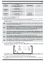
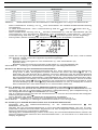
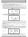
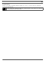
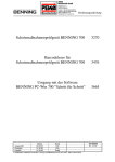
Bild 1:
Fig. 1: Fig. 1:
Obr. 1:
Gerätefrontseite
Appliance front face
Partie avant de l’appareil
Přední strana přístroje
Fig. 1:
Rys. 1:
Bild 1: Voorzijde van het apparaat
Panel przedni przyrządu
Framsida
9
J
K
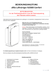
Bild 2:
Fig. 2: Fig. 2:
Obr. 2:
Geräteoberseite
Top side of the device
Face supérieure de l'appareil
Horní strana přístroje
02/ 2011
Fig. 2:
Rys. 2:
Bild 2: Bovenaanzicht apparaat
Górna strona urządzenia
Ovansida
BENNING ST 720
DFS
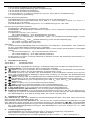
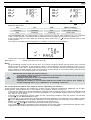
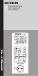
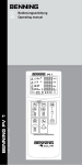
Bild 3:
Fig. 3: Fig. 3:
Obr. 3:
Fig. 3:
Rys. 3:
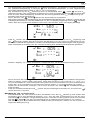
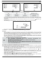
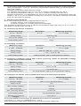
Bild 3: Spannungsmessung an externer Schutzkontaktsteckdose
Voltage measurement on external shock-proof socket
Mesure de tension sur une prise de courant de sécurité
externe
Měření napětí na externí zásuvce s ochranným
kontaktem
Spanningsmeting aan externe
veiligheidswandcontactdoos
Pomiar napięcia na zewnętrznym gniazdku wtykowym z
zestykiem ochronnym
Spänningsmätning på externa uttag
ST 720
LN
LE
NE
V
V
ON/OFF
press 2 sec.
IPE
IB
RPE
RISO
IPE (Ers.)
RISO
IB (Ers.)
IPE (Diff.)/IB (Dir.)
250 V
500 V
30 mA
RCD
3
Phase
RISO
250 V/500 V
FI/RCD
Test
RPE
IPE (Dir.)
230 V AC
DIN VDE 0701-0702, BGV A3, ÖVE/ÖNORM E 8701, NEN 3140
Prüfling während der Prüfung einschalten
Switch on test object during test
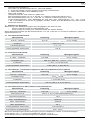
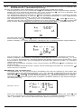
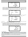
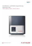
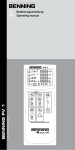
Bild 4:Prüfung von Geräten der Schutzklasse I (Geräte
mit Schutzleiter und berührbaren leitfähigen Teilen
die am Schutzleiter angeschlossen sind)
Fig. 4:Testing of devices of protection class I (devices
with protective conductor and accessible
conductive parts which are connected to the
protective conductor)
Fig. 4: Contrôle des appareils de la classe de protection
I (les appareils avec conducteur de protection et
avec des pièces touchables conductrices qui sont
connectées au conducteur de protection)
Obr. 4: Zkoušení zařízení třídy ochrany I (zařízení s
ochranným vodičem a vodivými díly nechráněnými
proti doteku, připojenými k ochrannému vodiči)
Fig. 4: Testen van apparaten van beschermklasse I
(apparaten met aardegeleider en aanraakbare
geleidende onderdelen die op de aardegeleider
zijn aangesloten)
Rys. 4: Testy urządzeń klasy ochronnej I (urządzenia
z przewodami ochronnymi i dotykającymi się i
przewodzącymi częściami, które są podłączone do
kabla ochronnego)
Bild 4: Test av utrustning med skyddsklass I (utrustning
med skyddsledare och åtkomstbara ledande delar
anslutna till skyddsledaren)
02/ 2011
ST 720
R PE
R ISO
M
mA
LEAK
ON/OFF
press 2 sec.
RPE
RISO
IPE
IB
RISO
230 V AC
IPE (Ers.)
IB (Ers.)
IPE (Diff.)/IB (Dir.)
250 V
500 V
30 mA
RCD
3
Phase
RISO
250 V/500 V
FI/RCD
Test
RPE
IPE (Dir.)
DIN VDE 0701-0702, BGV A3, ÖVE/ÖNORM E 8701, NEN 3140
Prüfling während der Prüfung einschalten
Switch on test object during test
BENNING ST 720
DFS
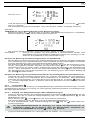
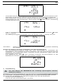
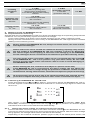
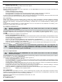
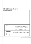
Bild 5:Prüfung von Geräten der Schutzklasse II
(Schutzisolierte Geräte ohne Schutzleiter und mit
berührbaren leitfähigen Teilen) bzw. Prüfung von
Geräten der Schutzklasse III (Schutzkleinspannung)
Fig. 5:Testing of devices of protection class II (shock-proof
devices without protective conductor and with
accessible conductive parts) and testing of devices of
protection class III (safety extra-low voltage)
Fig. 5: Contrôle des appareils de la classe de protection
II (appareils à double isolation sans conducteur
de protection et avec des pièces touchables
conductrices) et contrôle des appareils de la classe
de protection III (basse tension de protection)
Obr. 5: Zkoušení zařízení třídy ochrany II (zařízení s
ochrannou izolací bez ochranného vodiče a s
vodivými díly nechráněnými proti doteku) nebo
zkoušení zařízení třídy ochrany III (malé bezpečné
napětí)
Fig. 5: Testen van apparaten van beschermklasse II
(apparaten met randaarding zonder aardegeleider
en met aanraakbare geleidende onderdelen) resp.
testen van apparaten van beschermklasse III
(veiligheidslaagspanning)
Rys. 5: Testowanie urządzeń II klasy ochronnej (urządzenia
z izolacją ochronną bez kabla ochronnego i z
dotykającymi się i przewodzącymi częściami) lub
testowanie urządzeń III klasy ochronnej (małe
napięcie ochronne)
Bild 5: Test av utrustning med skyddsklass II (skyddsisolerad
utrustning utan skyddsledare och med åtkomstbara
ledande delar) resp. test av utrustning med
skyddsklass III (skyddsklenspänning)
ST 720
R ISO
M
mA
LEAK
ON/OFF
press 2 sec.
IPE
IB
RPE
RISO
IPE (Ers.)
RISO
IB (Ers.)
IPE (Diff.)/IB (Dir.)
250 V
500 V
30 mA
RCD
3
Phase
RISO
250 V/500 V
FI/RCD
Test
RPE
IPE (Dir.)
230 V AC
DIN VDE 0701-0702, BGV A3, ÖVE/ÖNORM E 8701, NEN 3140
Prüfling während der Prüfung einschalten
Switch on test object during test
Bild 6a: Prüfung von Geräteanschlussleitungen mit Kaltgerätestecker
Fig. 6a: Testing of device connecting cables with IEC connector
Fig. 6a:Contrôle des câbles de connexion d'appareil avec fiche mâle CEI
Obr. 6a: Zkouška připojovacích kabelů zařízení s připojovací zástrčkou
Fig. 6a: Testen van netvoedingskabels met apparaatstekker
Rys. 6a: Test kabli przyłączeniowych urządzeń z wtyczkami zimnych urządzeń
Bild 6a: Test av nätkablar med IEC-kontakt
ST 720
R PE
R ISO
M
ON/OFF
press 2 sec.
IPE
IB
RPE
RISO
IPE (Ers.)
RISO
IB (Ers.)
IPE (Diff.)/IB (Dir.)
250 V
500 V
30 mA
RCD
3
Phase
RISO
250 V/500 V
FI/RCD
Test
RPE
IPE (Dir.)
230 V AC
DIN VDE 0701-0702, BGV A3, ÖVE/ÖNORM E 8701, NEN 3140
Prüfling während der Prüfung einschalten
Switch on test object during test
02/ 2011
BENNING ST 720
DFS
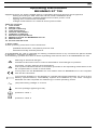
Bild 6b: Prüfung von Leitungen, Mehrfachverteilern und Leitungsroller
Fig. 6b: Testing of lines, multiple distributors and cable reels
Fig. 6b: Contrôle de câbles, de câbles de distribution multiple et
d'enrouleurs de câble
Obr. 6b: Zkoušení kabelů, vícenásobných rozvaděčů a kabelových cívek
Fig. 6b: Testen van kabels, verdeeldozen en kabelhaspels
Rys. 6b: Testowanie kabli, rozdzielnic wielokrotnych i bębnów kablowych
Bild 6b: Test av kablar, flerfördelare och kabeltrummor
ST 720
R PE
R ISO
M
ON/OFF
press 2 sec.
RPE
RISO
IPE
IB
RISO
230 V AC
IPE (Ers.)
IB (Ers.)
IPE (Diff.)/IB (Dir.)
250 V
500 V
30 mA
RCD
3
Phase
RISO
250 V/500 V
FI/RCD
Test
RPE
IPE (Dir.)
DIN VDE 0701-0702, BGV A3, ÖVE/ÖNORM E 8701, NEN 3140
Prüfling während der Prüfung einschalten
Switch on test object during test
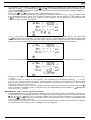
Bild 7:
Fig. 7:
Fig. 7:
Obr. 7:
Fig. 7:
Rys. 7:
Bild 7:
Prüfung von FI/RCD Schutzschalter (IΔN 30 mA)
RCD Testing (IΔN 30 mA)
Contrôle des dispositifs différentiels «RCD » (IΔN 30 mA)
Měření proudových chráničů RCD (IΔN 30 mA)
Testen van RCD veiligheidsschakelaar (IΔN 30 mA)
Kontrola wyłączników różnicowo-prądowych RCD (IΔN 30 mA)
Test av RCD skyddsströmställare (IΔN 30 mA)
ST 720
ms
0°
ON/OFF
press 2 sec.
IPE
IB
RPE
RISO
IPE (Ers.)
RISO
IB (Ers.)
IPE (Diff.)/IB (Dir.)
250 V
500 V
30 mA
RCD
3
Phase
RISO
250 V/500 V
FI/RCD
Test
RPE
IPE (Dir.)
230 V AC
DIN VDE 0701-0702, BGV A3, ÖVE/ÖNORM E 8701, NEN 3140
Prüfling während der Prüfung einschalten
Switch on test object during test
02/ 2011
BENNING ST 720
DFS
Bild 8:
Fig. 8:
Fig. 8:
Obr. 8:
Fig. 8:
Rys. 8:
Bild 8:
Prüfung 3-phasiger Prüfobjekte unter
Betriebsbedingung (isolierte Aufstellung des
Prüflings)
Testing three-phase test objects under
operating conditions (test sample placed on
insulated surface)
Contrôle des appareils triphasés sous
conditions de fonctionnement (mise en place
isolée de l'objet de contrôle)
Měření 3fázových zařízení při provozních
podmínkách (zařízení je izolačně oddělené)
Testen 3-fasige testobjecten onder
bedrijfsomstandigheden (geïsoleerde plaatsing
van het testobject)
Kontrola obiektów trójfazowych pod warunkiem
działania (próbka badana połozona na
izolowanej podstawce)
Test av 3-fasigt testobjekt under
driftförhållanden (isolerad uppställning av
testobjektet)
ST 720
R PE
R ISO
M
mA
LEAK
ON/OFF
press 2 sec.
IPE
IB
RPE
RISO
IPE (Ers.)
RISO
IB (Ers.)
IPE (Diff.)/IB (Dir.)
250 V
500 V
30 mA
RCD
3
Phase
RISO
250 V/500 V
FI/RCD
Test
RPE
IPE (Dir.)
230 V AC
DIN VDE 0701-0702, BGV A3, ÖVE/ÖNORM E 8701, NEN 3140
Prüfling während der Prüfung einschalten
Switch on test object during test
Bild 9:
Fig. 9:
Fig. 9:
Obr. 9:
Fig. 9:
Rys. 9:
Bild 9:
Batterie-/ Sicherungswechsel
Battery/ fuse replacement
Remplacement des piles/ fusibles
Výměna baterií/ pojistek
Vervanging van de batterijen/ smeltzekeringen
Wymiana baterii/ bezpiecznika
Batteri- /säkringsbyte
02/ 2011
BENNING ST 720
Option:
044140
044141
D
Bedienungsanleitung
BENNING ST 720
Gerätetester zur sicherheitstechnischen Prüfung ortsveränderlicher elektrischer Geräte/ Betriebsmittel
- Prüfung elektrischer Geräte gemäß DIN VDE 0701-0702, ÖVE/ ÖNORM E 8701
- Prüfung von Leitungsrollern, Mehrfachverteilern und Kaltgeräteleitungen
- Auslösezeitmessung von FI/RCD Schutzschalter
- Spannungsmessung an externer Schutzkontaktsteckdose
Inhaltsverzeichnis
1. Benutzerhinweise
2. Sicherheitshinweise
3. Lieferumfang
4. Gerätebeschreibung
5. Allgemeine Angaben
6. Umgebungsbedingungen
7. Elektrische Angaben
8. Prüfen mit dem BENNING ST 720
9. Instandhaltung
10.Umweltschutz
1.Benutzerhinweise
Diese Bedienungsanleitung richtet sich an
-
-
Elektrofachkräfte (EF), befähigte Personen und
Elektrotechnisch unterwiesene Personen (EuP)
Das BENNING ST 720 ist zur Messung in trockener Umgebung vorgesehen (näheres hierzu im
Abschnitt 6: Umgebungsbedingungen).
In der Bedienungsanleitung und auf dem BENNING ST 720 werden folgende Symbole verwendet:
Warnung vor elektrischer Gefahr!
Steht vor Hinweisen, die beachtet werden müssen, um Gefahren für Menschen zu
vermeiden.
Achtung Dokumentation beachten!
Das Symbol gibt an, dass die Hinweise in der Bedienungsanleitung zu beachten
sind, um Gefahren zu vermeiden.
Dieses Symbol auf dem BENNING ST 720 bedeutet, dass das BENNING ST 720
konform zu den EU-Richtlinien ist.
Dieses Symbol erscheint in der Anzeige für entladene Batterien. Sobald das
Batteriesymbol blinkt, tauschen Sie umgehend die Batterien gegen neue Batterien
aus. Geladene Batterien sind auch für die Messung im Netzbetrieb notwendig.
(AC) Wechsel- Spannung oder Strom.
Erde (Spannung gegen Erde).
02/ 2011
Schutzklasse I
Schutzklasse II
BENNING ST 720
1
D
2. Sicherheitshinweise
Das Gerät ist gemäß
DIN VDE 0404 Teil 1 und 2
DIN VDE 0411 Teil 1/ EN 61010 Teil 1
DIN VDE 0413 Teil 1/ EN 61557 Teil 1, 2, 4 und 10
gebaut und geprüft und hat das Werk in einem sicherheitstechnisch einwandfreien Zustand verlassen. Um diesen Zustand zu erhalten und einen gefahrlosen Betrieb sicherzustellen, muss
der Anwender die Hinweise und Warnvermerke beachten, die in dieser Anleitung enthalten sind.
Fehlverhalten und Nichtbeachtung der Warnungen kann zu schwerwiegenden Verletzungen
oder zum Tode führen.
Extreme Vorsicht bei Arbeiten um blanke Leiter oder Hauptleitungsträger. Ein
Kontakt mit Leitern kann einen Elektroschock verursachen.
Das BENNING ST 720 darf nur in Stromkreisen der Überspannungskategorie II
mit max. 300 V Leiter gegen Erde benutzt werden.
Beachten Sie, dass Arbeiten an spannungsführenden Teilen und Anlagen
grundsätzlich gefährlich sind. Bereits Spannungen ab 30 V AC und 60 V DC
können für den Menschen lebensgefährlich sein.
Das Gerät darf nur an ein Einphasen-Netz 230 V, 50 Hz mit einer Vorsicherung 16 A
angeschlossen werden. Beachten Sie, dass die maximale Schaltleistung/Lampenlast der Prüfsteckdose des BENNING ST 720, siehe Abschnitte 7.4 und 7.5., nicht
überschritten wird. Eine Überschreitung kann zur Auslösung der Sicherungen
und zur Beschädigung des BENNING ST 720 führen. Beschädigungen aufgrund
einer Überlast sind von möglichen Garantieansprüchen ausgeschlossen.
Vermeiden Sie wiederholte Schutzleiter- und Berührungsstrommessungen mit
30 Sekunden Messdauer an Prüfobjekten mit hoher Stromaufnahme (16 A).
Eine wiederholte Messung bei maximaler Last (16 A) kann das Geräteinnere
und somit auch die Geräteoberfläche erwärmen.
Die Messung des Schutzleiterwiderstandes kann durch parallel geschaltete
Impedanzen von zusätzlichen Betriebsstromkreisen und durch Ausgleichsströme verfälscht werden.
Die Messung des Schutzleiter- und Isolationswiderstandes darf nur an spannungslosen Anlageteilen durchgeführt werden.
Vor jeder Inbetriebnahme überprüfen Sie das Gerät und die Leitungen auf
Beschädigungen.
Ist anzunehmen, dass ein gefahrloser Betrieb nicht mehr möglich ist, ist das Gerät außer
Betrieb zu setzen und gegen unbeabsichtigten Betrieb zu sichern.
Es
-
-
-
-
-
ist anzunehmen, dass ein gefahrloser Betrieb nicht mehr möglich ist,
wenn das Gerät oder die Messleitungen sichtbare Beschädigungen aufweisen,
wenn das Gerät nicht mehr arbeitet,
nach längerer Lagerung unter ungünstigen Verhältnissen,
nach schweren Transportbeanspruchungen,
wenn das Gerät oder die Messleitungen feucht sind.
Um eine Gefährdung auszuschließen
- berühren Sie die Leitungen nicht an den blanken Messspitzen,
- stecken Sie die Leitungen in die entsprechend gekennzeichneten Buchsen
am Messinstrument
Wartung:
Das Gerät nicht öffnen, es enthält keine durch den Benutzer wartbaren Komponenten. Reparatur und Service kann nur durch qualifiziertes Personal erfolgen.
Reinigung:
Das Gehäuse regelmäßig mit einem Tuch und Reinigungsmittel trocken
abwischen. Kein Poliermittel oder Lösungsmittel verwenden.
3. Lieferumfang
Zum Lieferumfang des BENNING ST 720 gehören:
3.1 ein Stück BENNING ST 720,
02/ 2011
BENNING ST 720
2
D
3.2 ein Stück Prüfleitung mit Abgreifklemme,
3.3 ein Stück Kaltgeräteleitung (IEC-Adapterleitung)
3.4 ein Stück Netzanschlussleitung
3.5 ein Stück Kompakt-Schutztasche,
3.6 sechs Stück 1,5 V Mignon-Batterien/ Typ AA, IEC LR6 zur Erstbestückung
3.7 eine Bedienungsanleitung.
Hinweis auf Verschleißteile:
-Das BENNING ST 720 enthält zwei Sicherungen zum Überlastschutz:
Zwei Stück Sicherungen Nennstrom 16 A, 250 V, F, Trennvermögen ≥ 500 A, D = 5 mm, L =
20 mm (T. Nr. 10019440)
- Das BENNING ST 720 benötigt sechs 1,5-V-Batterien/Typ AA, IEC LR6
Hinweis auf optionales Zubehör:
- Prüfplaketten „Nächster Prüftermin“, 300 Stück
- Messadapter für dreiphasige Verbraucher (passiv, ohne netzspannungsabhängige Schalteinrichtungen)
zur Messung von RPE, RISO und IEA:
- 16 A CEE-Kupplung - 16 A Schukostecker (044122)
- 32 A CEE-Kupplung - 32 A Schukostecker (044123)
- Messadapter für dreiphasige Verbraucher (aktiv, mit netzspannungsabhängigen Schalt
einrichtungen)
zur Messung von RPE und IPE (direkte Messung) unter Funktionsbedingung:
- 16 A CEE 3-phasig aktiv (044140)
- 32 A CEE 3-phasig aktiv (044141)
alternativ:
- Leckstromzange BENNING CM 9 zur Messung von Differenz-, Schutzleiter- und Laststrom
an ein- und dreiphasigen Verbrauchern (044065)
- Messadapter für Leckstromzange BENNING CM 9, Leiter einzeln herausgeführt und doppelt
isoliert:
- 16 A Schukokupplung - 16 A Schukostecker (044131)
- 16 A CEE-Kupplung - 16 A CEE-Stecker (044127)
- 32 A CEE-Kupplung - 32 A CEE-Stecker (044128)
- Prüfprotkoll-Formulare “Prüfung elektrischer Geräte” können Sie kostenlos downloaden unter www.benning.de
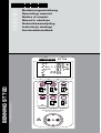
4. Gerätebeschreibung
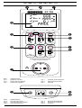
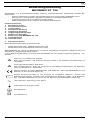
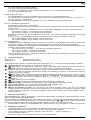
siehe Bild 1:
Gerätefrontseite
siehe Bild 2:
Geräteoberseite
Die in Bild 1 und 2 angegebenen Anzeige- und Bedienelemente werden wie folgt bezeichnet:
1 Prüfsteckdose, zum Anschluss des zu prüfenden Gerätes,
2
-Taste, Prüfung von Geräten der Schutzklasse I (Geräte mit Schutzleiter und berührbaren leitfähigen Teilen, die am Schutzleiter angeschlossen sind),
3
-Taste, Prüfung von Geräten der Schutzklasse II (Schutzisolierte Geräte ohne Schutzleiter und mit berührbaren leitfähigen Teilen) bzw. Prüfung von Geräten der Schutzklasse III
(Schutzkleinspannung),
4
-Taste, Prüfung des Schutzleiterstromes (Differenzmessung) bzw. Berührungsstromes
(direkte Messung) unter Funktionsbedingung (Prüfling wird mit Netzspannung versorgt)
5
-Taste, Reduzierung der Prüfspannung auf 250 VDC bzw. 500 VDC für Isolationswiderstandsmessung
6
-Taste, Prüfung von 30 mA FI/RCD-Schutzschaltern
7
-Taste, Prüfung 3-phasiger Geräte unter Funktionsbedingung
8 Digitalanzeige, zeigt den Prüffortschritt und einzelne Messergebnisse,
9 4 mm Prüfbuchse, zum Anschluss der Prüfleitung mit Abgreifklemme
J Kaltgerätestecker (IEC-Stecker), zum Anschluss der Kaltgeräteleitung
K Netzanschlussbuchse, zum Anschluss der Netzspannung (230 V, 50 Hz), zur Spannungsmessung an externer Schutzkontaktsteckdose bzw. zum Anschluss der Messsignalleitung
des Messadapters 16 A CEE 3-phasig aktiv/ 32 A CEE 3-phasig aktiv.
5. Allgemeine Angaben
Das BENNING ST 720 führt elektrische Sicherheitsüberprüfungen nach DIN VDE 0701-0702,
BGV A3 und ÖVE/ ÖNORM E8701 aus.
Eigenständig überprüft das BENNING ST 720 die Art des angeschlossenen Prüfobjekts und gibt
dem Benutzer einen Hinweis bei unkorrekter Auswahl der Prüfablaufs [2...3]: Voreingestellte
Grenzwerte und Messergebnisse mit gut/ schlecht Aussage erleichtern die Bewertung der Prüfung.
- Bei voller Batteriekapazität ermöglicht das BENNING ST 720 eine Anzahl von ca. 2500
Geräteprüfungen.
6. -
-
-
Umgebungsbedingungen
Das BENNING ST 720 ist für Messungen in trockener Umgebung vorgesehen.
Barometrische Höhe bei Messungen: Maximal 2000 m
Überspannungskategorie/ Aufstellungskategorie: IEC 61010-1 → 300 V Kategorie II,
02/ 2011
BENNING ST 720
3
D
-
-
-
-
-
Verschmutzungsgrad: 2,
Schutzart: IP 40 (DIN VDE 0470-1, IEC/ EN 60529)
4 - erste Kennziffer: Schutz gegen kornförmige Fremdkörper
0 - zweite Kennziffer: Kein Wasserschutz,
EMC: EN 61326-1,
Arbeitstemperatur und relative Luftfeuchte:
Bei Arbeitstemperatur von 0 °C bis 30 °C: relative Luftfeuchte kleiner 80 %,
Bei Arbeitstemperatur von 31 °C bis 40 °C: relative Luftfeuchte kleiner 75 %,
Lagerungstemperatur: Das BENNING ST 720 kann bei Temperaturen von - 25 °C bis
+ 65 °C (Luftfeuchte 0 bis 80 %) gelagert werden. Dabei sind die Batterien aus dem Gerät
herauszunehmen.
7. Elektrische Angaben
Bemerkung: Die Messgenauigkeit wird angegeben als Summe aus
- einem relativen Anteil des Messwertes und
- einer Anzahl von Digit (d.h. Zahlenschritte der letzten Stelle).
Diese Messgenauigkeit gilt bei Temperaturen von 18 °C bis 28 °C und einer relativen Luftfeuchtigkeit kleiner 80 %.
7.1Schutzleiterwiderstand
Messbereich
Auflösung
0,05 Ω - 19,99 Ω
0,01 Ω
Messgenauigkeit
5 % ± 2 Digit
Prüfstrom:
> 200 mA (2 Ω)
Leerlaufspannung:
4V-9V
Voreingestellter Grenzwert:
0,3 Ω
7.2Isolationswiderstand
Messbereich
Auflösung
Messgenauigkeit
0,1 MΩ - 19,99 MΩ
0,01 MΩ
5 % ± 2 Digit
Prüfspannung:
250 VDC/ 500 VDC, + 20 %, - 0 %
Prüfstrom:
> 1 mA, < 2 mA bei 2 kΩ
Voreingestellter Grenzwert:
1 MΩ (SK I), 2 MΩ (SK II)
7.3 Schutzleiter- und Berührungsstrom über Ersatzableitstromverfahren
Messbereich
Auflösung
Messgenauigkeit
0,25 mA - 19,99 mA
0,01 mA
5 % ± 2 Digit
Prüfspannung:
40 VAC, 50 Hz
Prüfstrom:
< 10 mA bei 2 kΩ
Voreingestellter Grenzwert:
3,5 mA (SK I), 0,5 mA (SK II)
7.4 Schutzleiterstrom über Differenzstromverfahren
Messbereich
Auflösung
Messgenauigkeit
0,25 mA - 19,99 mA
0,01 mA
5 % ± 2 Digit
Nennspannung:
230 V ± 10 % (wie Netzeinspeisung)
Bemessungsstrom:
16 A
Max. Schaltleistung:
3000 VA
Max. Lampenlast:
1000 W
Max. Messdauer:
30 s
Voreingestellter Grenzwert:
3,5 mA (SK I)
Fremdspannungsfestigkeit:
max. 276 V
Bei nicht-sinusförmiger Stromversorgung ist ein zusätzlicher Fehler zu berücksichtigen:
Crest-Factor von > 1,4 bis 2,0 zusätzlicher Fehler + 0,4 %
Fremdfelder können das Messergebnis zusätzlich beeinflussen.
02/ 2011
BENNING ST 720
4
D
7.5 Berührungsstrom über direktes Messverfahren
Messbereich
Auflösung
Messgenauigkeit
0,1 mA - 1,99 mA
0,01 mA
5 % ± 2 Digit
Nennspannung:
230 V ± 10 % (wie Netzeinspeisung)
Bemessungsstrom:
16 A
Max. Schaltleistung:
3000 VA
Max. Lampenlast:
1000 W
Max. Messdauer:
30 s
Voreingestellter Grenzwert:
0,5 mA (SK II)
Fremdspannungsfestigkeit:
max. 276 V
Bei nicht-sinusförmiger Stromversorgung ist ein zusätzlicher Fehler zu berücksichtigen:
Crest-Factor von >1,4 bis 2,0, zusätzlicher Fehler + 3,1 %
7.6Leitungstest
- Messung des Schutzleiterwiderstandes gemäß 7.1
- Messung des Isolationswiderstandes gemäß 7.2
- Leitungsbruchprüfung von Außenleiter (L) und Neutralleiter (N)
- Kurzschlussprüfung von Außenleiter (L) und Neutralleiter (N)
7.7 Auslösezeitmessung von FI/RCD Schutzschalter
Messbereich
Auflösung
Messgenauigkeit
10 ms - 500 ms
1 ms
5 % ± 2 Digit
Prüfstrom/ Polarität:
30 mA sinusförmig/ 0° und 180°
Voreingestellter Grenzwert:
200 ms
7.8Schutzleiterstrom über direktes Messverfahren (3-phasige Prüfobjekte unter Betriebsbedingung)
Messbereich
Auflösung
Messgenauigkeit
0,25 mA - 9,99 mA
0,01 mA
5 % ± 2 Digit
Nennspannung:
3 x 400 V ± 10 % (wie Netzeinspeisung)
Bemessungstrom:
16 A bzw. 32 A
Voreingestellter Grenzwert:
3,5 mA
7.9 Spannungsmessung an externer Schutzkontaktsteckdose
Messbereich
Auflösung
Messgenauigkeit
Überlastschutz
50 V - 270 VAC
1V
5 % ± 2 Digit
300 V
Anzeige:
- Spannung zwischen Außenleiter (L) und Neutralleiter (N)
- Spannung zwischen Außenleiter (L) und Erdleiter (PE)
- Spannung zwischen Neutralleiter (N) und Erdleiter (PE)
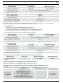
7.10 Grenzwerte gemäß DIN VDE 0701-0702, bzw. ÖVE/ ÖNORM E 8701-1
Hinweis:
Voreingestellte Grenzwerte in Fettdruck sind im BENNING ST 720 hinterlegt.
Schutzklasse I
Schutzleiter
widerstand
RPE
02/ 2011
Schutzklasse II, III
Für Leitungen mit einem
Bemessungsstrom ≤ 16 A:
≤ 0,3 Ω bis 5 m Länge,
je weitere 7,5 m: zusätzlich 0,1 Ω,
max. 1 Ω,
Für Leitungen mit höheren
Bemessungsströmen gilt der berechnete ohmsche Widerstandswert
BENNING ST 720
Leitungsprüfung
≤ 0,3 Ω
(siehe SK I)
5
D
Isolationswiderstand
RISO
Schutzleiterstrom
IEA/ ILEAK
Berührungsstrom
IEA/ ILEAK
≥ 1 MΩ
≥ 2 MΩ für den Nachweis
der sicheren Trennung (Trafo)
≥ 0,3 MΩ bei Geräten mit
Heizelementen
≥ 2 MΩ (SK II),
≥ 0,25 MΩ (SK III),
≥ 1 MΩ
≤ 3,5 mA
an leitfähigen Teilen mit
PE-Verbindung
1 mA/ kW bei Geräten mit
Heizelementen P > 3,5 kW
≤ 0,5 mA
an leitfähigen Teilen ohne
PE-Verbindung
≤ 0,5 mA
an leitfähigen
Teilen ohne
PE-Verbindung
8. Prüfen mit dem BENNING ST 720
8.1 Vorbereiten der Prüfung
Benutzen und lagern Sie das BENNING ST 720 nur bei den angegebenen Lager- und Arbeitstemperaturbedingungen, vermeiden Sie dauernde Sonneneinstrahlung.
- Angaben von Nennspannung und Nennstrom auf den Sicherheitsmessleitungen überprüfen.
- Starke Störquellen in der Nähe des BENNING ST 720 können zu instabiler Anzeige und zu
Messfehlern führen.
Vor jeder Inbetriebnahme überprüfen Sie das Gerät, die Leitungen und das
Prüfobjekt auf Beschädigungen.
Beachten Sie, dass die maximale Schaltleistung/Lampenlast der Prüfsteckdose
des BENNING ST 720, siehe Abschnitte 7.4 und 7.5., nicht überschritten
wird. Eine Überschreitung kann zur Auslösung der Sicherungen und zur
Beschädigung des BENNING ST 720 führen. Beschädigungen aufgrund einer
Überlast sind von möglichen Garantieansprüchen ausgeschlossen.
Der Stecker der Netzanschlussleitung ist in die Buchse K des BENNING ST 720
nur in einer Position einsteckbar (siehe weiße Markierung). Üben Sie auf den
Stecker der Netzanschlussleitung keine Kraft aus, um Beschädigungen am
BENNING ST 720 zu vermeiden.
Vor Prüfbeginn ist das Prüfobjekt einzuschalten. (Netzschalter ein)
Bei Anschluss des BENNING ST 720 an Netzspannung wird das Prüfobjekt während
der Schutzleiter-/ Berührungsstrommessung mit Netzspannung versorgt. Kontrollieren Sie die ordnungsgemäße Funktion des Prüfobjektes während der Messung!
Zur Beginn der Prüfung ist zu prüfen, ob der gewählte Prüfablauf zur
Schutzklasse des angeschlossenen Prüfobjektes stimmt.
8.1.1 Ein-, Ausschalten des BENNING ST 720
- Durch gleichzeitiges betätigen der Tasten 2 + 3 für ca. 3 Sekunden wird das
BENNING ST 720 eingeschaltet, Signaltöne bestätigen dies. Erneutes drücken der Tasten
schaltet das Gerät aus.
-
Das BENNING ST 720 schaltet sich nach ca. 2 Minuten selbstständig ab. (APO, AutoPower-Off). Es schaltet sich wieder ein, wenn die Tasten 2 + 3 betätigt werden. Ein
Signalton signalisiert die selbsttätige Abschaltung des Gerätes.
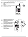
8.1.2 Prüfung der Netzspannung an externer Schutzkontaktsteckdose
- Schließen Sie die Netzanschlussleitung an die Netzanschlussbuchse
BENNING ST 720 an.
02/ 2011
BENNING ST 720
K
des
6
D
-
-
Schließen Sie den Schukostecker an die zu überprüfende Schutzkontaktsteckdose an. Bei
anliegender Netzspannung wird die Spannungsmessung automatisch gestartet.
Abhängig der Außenleiterlage (rechts oder links) der Schutzkontaktsteckdose werden die
Spannungspotentiale zwischen den Anschlussklemmen L, N und PE für ca. 3 Sekunden im
Display angezeigt.
oder
-
Falls die Spannungspotentiale innerhalb nachfolgender Grenzwerte liegen, erscheint ein
neben den LN-, LE- und NE-Symbolen.
LN
195 V - 253 V
LE
195 V - 253 V
NE
< 30 V
LN
oder
195 V - 253 V
LE
< 30 V
NE
195 V - 253 V
Es werden nur die Spannungspotentiale zwischen den einzelnen Anschlüssen
L, N und PE gemessen. Die Messung gibt keine Aussage über die fachgerechte
Installation der Schutzkontaktsteckdose. Kein Warnhinweis bei gefährlicher
Berührungsspannung des PE-Leiters!
Das BENNING ST 720 darf nicht dauerhaft an Netzspannung angeschlossen
werden.
-
Nach 3 Sekunden schaltet das BENNING ST 720 automatisch in den Bereitschaftsmodus
zurück.
siehe Bild 3:
Spannungsmessung an externer Schutzkontaktsteckdose
8.1.3Prüfablauf
Das BENNING ST 720 führt elektrische Sicherheitsüberprüfungen nach DIN VDE 0701-0702
bzw. ÖVE/ ÖNORM E 8701 aus. Ausführliche Informationen zu den Prüfungen und Grenzwerten
sind den Normen in der aktuellen Fassung zu entnehmen.
Eigenständig überprüft das BENNING ST 720 die Art des angeschlossenen Prüfobjekts und gibt
den Benutzer einen Hinweis bei falsch vorgewähltem Prüfablauf [2...3].
Hinweis:
- Das BENNING ST 720 kann Prüfungen im Batteriebetrieb und im Netzbetrieb mit Anschluss
der 230 V Netzspannung durchführen. Im Batteriebetrieb ist zu beachten, dass die Messung
des Schutzleiter- und Berührungsstromes im Ersatzableitstromverfahren durchgeführt
wird. Dieses Verfahren ist für Prüfobjekte geeignet, die keine netzspannungsabhängigen
Schaltelemente (z.B. Netzteile) enthalten.
- Ist der interne Aufbau des Prüfobjekts unbekannt oder enthält das Prüfobjekt
netzspannungsabhängige Schaltelemente, ist die Prüfung im Netzbetrieb mit Anschluss der
230 V Netzspannung durchzuführen. Sobald das BENNING ST 720 über die Buchse K mit
Netzspannung versorgt wird, erfolgt die Schutzleiterstrom-/Berührungsstrommessung automatisch
im Differenzstrom-/direkten Messverfahren unter Betriebsbedingungen des Prüfobjekts.
- Die Prüfspannung für die Isolationswiderstandsmessung ist gemäß Norm auf 500 VDC
voreingestellt. Für Prüfobjekte mit integrierten Überspannungsableitern und für elektronische
Geräte bei denen Bedenken gegen eine Prüfspannung von 500 VDC besteht, kann die
Prüfspannung über
-Taste 5 auf 250 VDC reduziert werden.
8.2Prüfung elektrischer Geräte/ Betriebsmittel nach DIN VDE 0701-0702, bzw. ÖVE/
ÖNORM E 8701
Vor Prüfbeginn ist das Prüfobjekt einer Sichtprüfung zu unterziehen, bei evtl.
Beschädigungen ist die Prüfung abzubrechen.
8.2.1 Prüfung von Geräten der Schutzklasse I
Prüfung von Geräten mit Schutzleiter und berührbaren leitfähigen Teilen, die am Schutzleiter
angeschlossen sind.
- Das Prüfobjekt muss an die Prüfsteckdose 1 des BENNING ST 720 angeschlossen werden.
- Stecken Sie den 4 mm Sicherheitsstecker der Prüfleitung mit Abgreifklemme in die 4 mm Sicherheitsbuchse 9 und stellen Sie eine Verbindung mit einem Metallteil des Prüfobjekts her.
02/ 2011
BENNING ST 720
7
D
-
-
-
-
-
Für Netzbetrieb (Schutzleiterstrom im Differenzverfahren, Prüfobjekt in Funktion!) Stecker
der Netzanschlussleitung in Buchse K und Schutzkontaktstecker in eine abgesicherte
Schutzkontaktsteckdose (230 V, 50 Hz, 16 A) einstecken.
Die Prüfspannung der RISO-Messung kann im Bedarfsfall über
-Taste 5 auf 250 VDC
reduziert werden. Die eingestellte Prüfspannung wird kurzzeitig im Display 8 eingeblendet.
Eine erneute Tastenbetätigung schaltet auf die voreingestellte 500 VDC Prüfspannung um.
Schalten Sie das Prüfobjekt ein.
Durch drücken der
-Taste 2 startet der automatische Prüfablauf.
Die Prüfung beginnt mit der Messung des Schutzleiterwiderstandes RPE. Falls RPE größer als der
zulässige Grenzwert ist, wird der Messwert von RPE im Display angezeigt und ein
erscheint
neben dem RPE-Symbol. Der Abbruch wird durch den Hinweis „FAIL“ im Display bestätigt.
-
Falls RPE kleiner als der zulässige Grenzwert ist, wird der Messwert von RPE angezeigt und
ein
erscheint neben dem RPE-Symbol. Die Messung von RPE wird nun wiederholt mit vertauschter Polarität durchgeführt und der höchste Messwert beider Messungen wird angezeigt.
Nach bestandener Prüfung von RPE wird die Prüfung des Isolationswiderstandes gestartet.
-
Sollte im Display „Lo LOAD“ erscheinen, überprüfen Sie, ob das Prüfobjekt eingeschaltet ist.
-
-
Durch drücken der Taste 2 wird bei zu geringer Last (RL-N > 6 kΩ) der Prüfablauf fortgesetzt.
Sollte im Display „HIGH LOAD“ erscheinen, weist dies auf eine zu hohe Last (RL-N << 14 Ω, ILast >
16 A) im Prüfobjekt hin. Eventuell besteht die Gefahr eines Kurzschlusses bzw. eines Erdschlusses.
Prüfen Sie, ob im Prüfobjekt ein Kurzschluss zwischen Außen- (L) und Neutralleiter (N) vorliegt.
Sollte kein Kurzschluss vorliegen, kann durch drücken der Taste 2 der Prüfablauf fortgesetzt werden.
Falls der Isolationswiderstand RISO größer als der zulässige Grenzwert ist, erscheint ein
neben dem RISO-Symbol.
-
-
BENNING ST 720 im Netzbetrieb:
- Das BENNING ST 720 unterbricht den Prüfablauf nach der RISO-Messung und fordert den
Anwender durch eine blinkende Anzeige „ILEAK“ auf, die 230 V Netzspannung auf die Prüfsteckdose 1 zu schalten. Vergewissern Sie sich, dass der Prüfling gesichert ist und drücken
Sie die
-Taste 4, um den Schutzleiterstrom im Differenzstromverfahren zu messen.
- Die Messung des Schutzleiterstromes (Differenzstromverfahren) startet nur bei korrekt anliegender Netzspannung.
02/ 2011
BENNING ST 720
8
D
Schritt 1 von 2:
-
Nach einer Messzeit von 5 Sekunden oder durch eine erneute Betätigung der Taste 4 wird
das Netz umgepolt und der Schutzleiterstrom wird mit umgepolter Netzspannung („L/N“ –
„N/L") gemessen. Der höchste Messwert beider Messungen wird angezeigt.
Schritt 2 von 2:
-
-
Falls der Schutzleiterstrom kleiner als der zulässige Grenzwert ist, erscheint ein
neben
dem ILEAK-Symbol.
Die Gesamtprüfung gilt als bestanden, wenn das Symbol „PASS“ im Display erscheint.
alternativ:
BENNING ST 720 im Batteriebetrieb (ohne Netzversorgung):
- Ebenso erscheint ein
neben dem IEA-Symbol, falls der Schutzleiterstrom IEA (Ersatzableitstromverfahren) kleiner als der zulässige Grenzwert ist.
- Die Prüfung gilt als bestanden, wenn das Symbol „PASS“ im Display erscheint.
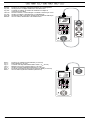
siehe Bild 4:Prüfung von Geräten der Schutzklasse I (Geräte mit Schutzleiter und berührbaren leitfähigen Teilen die am Schutzleiter angeschlossen sind)
Hinweis zur Messung des Schutzleiterwiderstandes:
-
Die Messung des Schutzleiterwiderstandes RPE kann alternativ auch als Dauermessung (max. 4 Min.) durchgeführt werden. Drücken Sie hierzu die Taste 2 für ca. > 5
Sekunden bis das Symbol im Display erscheint. Bewegen Sie die Anschlussleitung
des Prüfobjektes über die komplette Länge, um eine Schwachstelle oder einen Bruch in
der Schutzleiterbahn festzustellen. Das BENNING ST 720 erfasst fortlaufend den aktuellen Messwert im Display und hinterlegt den Maximalwert im Speicher. Durch erneuten
Druck auf die Taste 2 wird die Messung mit vertauschter Polarität durchgeführt. Eine
erneute Betätigung der Taste 2 zeigt den Maximalwert von RPE im Display an und führt
den Prüfablauf, wie unter Abschnitt 8.2.1 beschrieben, weiter fort.
Hinweis zur Messung des Schutzleiterstromes im Netzbetrieb:
-
Die Messung des Schutzleiterstromes ILEAK kann alternativ auch als Dauermessung
(max. 30 Sekunden) durchgeführt werden. Drücken Sie hierzu die Taste 4 für ca. > 5
Sekunden, um die Dauermessung zu starten. Nach 30 Sekunden erfolgt die Umpolung
der Netzspannung („L/N“ – „N/L") automatisch. Durch eine frühere Betätigung der Taste 4 kann die Umpolung der Netzspannung manuell durchgeführt bzw. die Messung
durch eine weitere Betätigung der Taste 4 beendet werden.
Hinweis zur Messung des Berührungsstromes:
-
Berührbare leitfähige Teile, die nicht mit dem Schutzleiter verbunden sind, sind gemäß
Abschnitt 8.2.2 zu prüfen. Das BENNING ST 720 muss für die Messung des Berührungsstromes (direktes Verfahren) mit 230 V Netzspannung betrieben werden.
-
Bei der Berührungsstrommessung im direkten Messverfahren darf kein Teil des Prüfobjektes eine Verbindung zum Erdpotential haben. Das Prüfobjekt ist isoliert aufzustellen.
Ansonsten könnten Ableitströme gegen Erde das Messergebiss beeinflussen.
02/ 2011
BENNING ST 720
9
D
8.2.2Prüfung von Geräten der Schutzklasse II (Schutzisoliert) und von Geräten der
Schutzklasse III (Schutzkleinspannung)
Prüfung von Geräten ohne Schutzleiter und mit berührbaren leitfähigen Teilen.
- Das Prüfobjekt muss an die Prüfsteckdose 1 des BENNING ST 720 angeschlossen werden.
- Stellen Sie eine Verbindung zwischen der 4 mm Prüfbuchse 9 und einem Metallteil des
Prüfobjekts mittels der Prüfleitung mit Abgreifklemme her.
- Für Netzbetrieb (Berührungsstrom im direkten Verfahren, Prüfobjekt in Funktion!) Stecker
der Netzanschlussleitung in Buchse K und Schutzkontaktstecker in eine abgesicherte
Schutzkontaktsteckdose (230 V, 50 Hz, 16 A) einstecken.
- Die Prüfspannung der RISO-Messung kann im Bedarfsfall über
-Taste 5 auf 250 VDC
reduziert werden. Die eingestellte Prüfspannung wird kurzzeitig im Display 8 eingeblendet.
Eine erneute Tastenbetätigung schaltet auf die voreingestellt 500 VDC Prüfspannung um.
-
-
-
Schalten Sie das Prüfobjekt ein.
Durch drücken der
-Taste 3 startet der automatische Prüfablauf.
Sollte im Display „Lo LOAD“ erscheinen, überprüfen Sie, ob das Prüfobjekt eingeschaltet ist.
-
-
Durch drücken der Taste 3 wird bei zu geringer Last (RL-N > 6 kΩ) der Prüfablauf fortgesetzt.
Sollte im Display „HIGH LOAD“ erscheinen, weist dies auf eine zu hohe Last (RL-N << 14 Ω,
ILast > 16 A) im Prüfobjekt hin. Eventuell besteht die Gefahr eines Kurzschlusses bzw. eines
Erdschlusses. Prüfen Sie, ob im Prüfobjekt ein Kurzschluss zwischen Außen- (L) und Neutralleiter (N) vorliegt.
Sollte kein Kurzschluss vorliegen, kann durch drücken der
-Taste 3 der Prüfablauf fortgesetzt werden.
Falls der Isolationswiderstand RISO größer als der zulässige Grenzwert ist, erscheint ein
neben dem RISO-Symbol.
-
-
BENNING ST 720 im Netzbetrieb:
- Das BENNING ST 720 unterbricht den Prüfablauf nach der RISO-Messung und fordert den
Anwender durch eine blinkende Anzeige „ILEAK“ auf, die 230 V Netzspannung auf die Prüfsteckdose 1 zu schalten. Vergewissern Sie sicher, dass der Prüfling gesichert ist und drücken Sie die
-Taste 4, um den Berührungsstrom ILEAK (direktes Verfahren) zu messen.
- Die Messung des Berührungsstromes im direkten Verfahren startet nur bei korrekt anliegender Netzspannung.
Schritt 1 von 2:
-
ach einer Messzeit von 5 Sekunden oder durch eine erneute Betätigung der Taste 4 wird
N
das Netz umgepolt und der Berührungsstrom wird mit umgepolter Netzspannung („L/N“ –
„N/L") gemessen. Der höchste Messwert beider Messungen wird angezeigt.
02/ 2011
BENNING ST 720
10
D
Schritt 2 von 2:
-
-
Falls der Berührungsstrom kleiner als der zulässige Grenzwert ist, erscheint ein
neben
dem ILEAK-Symbol.
Die Gesamtprüfung gilt als bestanden, wenn das Symbol „PASS“ im Display erscheint.
alternativ:
BENNING ST 720 im Batteriebetrieb (ohne Netzversorgung):
- Ebenso erscheint ein
neben dem IEA-Symbol, falls der Berührungsstrom IEA (Ersatzableitstromverfahren) kleiner als der zulässige Grenzwert ist.
- Die Prüfung gilt als bestanden, wenn das Symbol „PASS“ im Display erscheint.
siehe Bild 5:Prüfung von Geräten der Schutzklasse II (Schutzisolierte Geräte ohne
Schutzleiter und mit berührbaren leitfähigen Teilen) bzw. Prüfung von Geräten der Schutzklasse III (Schutzkleinspannung)
Hinweis zur Messung des Berührungsstromes im Netzbetrieb:
- Bei der Berührungsstrommessung im direkten Messverfahren darf kein Teil des Prüfobjektes
eine Verbindung zum Erdpotential haben. Das Prüfobjekt ist isoliert aufzustellen. Ansonsten
könnten Ableitströme gegen Erde das Messergebnis beeinflussen.
- Die Messung des Berührungsstromes ILEAK kann alternativ auch als Dauermessung (max.
30 sec.) durchgeführt werden. Drücken Sie hierzu die Taste 4 für ca. > 5 Sekunden um
die Dauermessung zu starten. Nach 30 Sekunden erfolgt die Umpolung der Netzspannung
(„L/N“ – „N/L") automatisch. Durch eine frühere Betätigung der Taste 4 kann die Umpolung
der Netzspannung manuell durchgeführt bzw. die Messung durch eine weitere Betätigung
der Taste 4 beendet werden.
Hinweis zur Messung des Isolationswiderstandes bei Prüfobjekten des Schutzklasse III:
- Aufgrund des voreingestellten Grenzwertes von 2 MΩ für Prüfobjekte der Schutzklasse II,
ist bei der Prüfung von Prüfobjekten der Schutzklasse III zu beachten, dass Messwerte
zwischen den Grenzwerten von 2 MΩ (SK II) bis 0,25 MΩ (SK III) mit einem
neben dem
RISO-Symbol dargestellt werden. In diesem Fall ist der Messwert von der befähigten Person
zu beurteilen.
8.2.3Leitungstest
Der Leitungstest kann zur Prüfung von Kaltgeräteleitungen (Geräteanschlussleitungen mit Kaltgerätekupplung) als auch zur Prüfung von Leitungsroller, Mehrfachverteilern und Verlängerungsleitungen genutzt werden.
8.2.3.1 Prüfung von Kaltgeräteleitungen (IEC-Adapterleitungen)
- Entfernen Sie den Stecker der Netzanschlussleitung aus Buchse K des BENNING ST 720.
- Schließen Sie die zu prüfende Kaltgeräteleitung über den Kaltgerätestecker J an das
BENNING ST 720 an.
- Durch drücken der
-Taste 2 startet der automatische Prüfablauf.
- Die Prüfung beginnt mit der Messung des Schutzleiterwiderstandes RPE.
- Je nach Grenzwertüber- oder -unterschreitung wird ein
oder ein
neben dem RPESymbol angezeigt.
-
Der Schutzleiterwiderstand ist abhängig von Länge und Querschnitt der zu
prüfenden Leitung. Es ist möglich, dass das Messergebnis akzeptabel ist,
obwohl das BENNING ST 720 ein
neben RPE darstellt.
Typische Widerstandswerte von Leitungen sind der Tabelle 1 zu entnehmen.
02/ 2011
BENNING ST 720
11
D
Querschnitt
Länge
1,0 mm²
1,5 mm²
2,5 mm²
5m
0,1 Ω
0,06 Ω
0,04 Ω
10 m
0,2 Ω
0,12 Ω
0,08 Ω
25 m
0,5 Ω
0,3 Ω
0,2 Ω
50 m
1,0 Ω
0,6 Ω
0,4 Ω
Tabelle 1:
-
-
-
-
Widerstandwerte des Schutzleiters in Abhängigkeit von Länge und Querschnitt
Nach bestandener Prüfung von RPE wird automatisch die Isolationswiderstandsmessung
durchgeführt.
Je nach Grenzwertüber- oder -unterschreitung wird ein
oder ein
neben dem RISOSymbol angezeigt.
Nach bestandener Prüfung von RISO wird der Außenleiter (L) und der Neutralleiter (N) auf
Leitungsbruch und Kurzschluss überprüft. Eine bestandene Leitungsbruch- und Kurzschlussprüfung wird über ein
neben dem
und dem Symbol „Good“ angezeigt.
Das Symbol „PASS“ bestätigt die erfolgreiche Prüfung des kompletten Prüfablaufs.
- Sollte die Leitungsbruch- oder die Kurzschlussprüfung nicht bestanden sein, wird an Stelle
des Symbol „Good“ eines der folgende Symbole angezeigt:
- Symbol „OPEN“:
Bestätigt den Leitungsbruch von Außenleiter (L) oder Neutralleiter (N)
- Symbol „Shor“:
Bestätigt den Kurzschluss zwischen Außenleiter (L) und Neutralleiter (N)
siehe Bild 6a: Prüfung von Geräteanschlussleitungen mit Kaltgerätestecker
Hinweis zur Messung des Schutzleiterwiderstandes:
-
Die Messung des Schutzleiterwiderstandes RPE kann alternativ auch als Dauermessung (max. 3 Min.) durchgeführt werden. Drücken Sie hierzu die Taste 2 für ca. > 5
Sekunden bis das Symbol im Display erscheint. Bewegen Sie die Anschlussleitung
des Prüfobjektes über die komplette Länge, um eine Schwachstelle oder einen Bruch in
der Schutzleiterbahn festzustellen. Das BENNING ST 720 erfasst fortlaufend den aktuellen Messwert im Display und hinterlegt den Maximalwert im Speicher. Durch erneuten
Druck auf die Taste 2 wird die Messung mit vertauschter Polarität durchgeführt. Eine
erneute Betätigung der Taste 2 zeigt den Maximalwert von RPE im Display an und führt
den Prüfablauf wie unter Abschnitt 8.2.3.1 beschrieben weiter fort.
8.2.3.2 Prüfung von Leitungsroller, Mehrfachverteilern und Verlängerungsleitungen
- Entfernen Sie den Stecker der Netzanschlussleitung aus Buchse K des BENNING ST 720.
- Schließen Sie die im Lieferumfang befindliche Kaltgeräteleitung (IEC-Adapterleitung) an
den Kaltgerätestecker J des BENNING ST 720 an.
- Die zu prüfende Leitung wird an die Prüfsteckdose 1 und den Schukostecker der Kaltgeräteleitung angeschlossen.
- Durch drücken der Taste 2 startet der automatische Prüfablauf.
- Der weitere Prüfablauf entspricht dem Prüfablauf von Abschnitt 8.2.3.1.
siehe Bild 6b: Prüfung von Leitungen, Mehrfachverteilern und Leitungsroller
8.3 Prüfung von FI/RCD Schutzschalter mit 30 mA Nennfehlerstrom
- Schließen Sie die Netzanschlussleitung an die Netzanschlussbuchse K des
BENNING ST 720 an.
- Stecken Sie den Schutzkontaktstecker in eine Schutzkontaktsteckdose, die vom zu überprüfenden FI/RCD-Schutzschalter abgesichert ist. Bei anliegender Netzspannung wird die
Spannungsmessung automatisch gestartet.
- Abhängig der Außenleiterlage (rechts oder links) der Schutzkontaktsteckdose werden die
Spannungspotentiale zwischen den Anschlussklemmen L, N und PE für ca. 2 Sekunden im
Display angezeigt.
02/ 2011
BENNING ST 720
12
D
oder
-
Durch drücken der
-Taste 6 wird bei korrekter Netzspannung (Symbole "LN" und "LE"
im Display) die Prüfung des FI/RCD-Schutzschalters gestartet.
LN
LE
NE
Netzspannung
Blinkend
Blinkend
AUS
Keine Netzspannung
AUS
Blinkend
Blinkend
Erdfehler
- Das BENNING ST 720 erzeugt einen Fehlerstrom von 30 mA mit positiver (0°) bzw. negativer (180°) Anfangspolarität. Der FI/RCD-Schutzschalter löst aus und die Auslösezeit wird
gemessen.
- Falls die Auslösezeit kleiner als der Grenzwert (200 ms) ist, erscheint ein
neben der
Auslösezeit.
- Die Prüfung gilt als bestanden, wenn das Symbol „PASS“ im Display erscheint.
- Die Prüfung ist mit umgekehrter Anfangspolarität zu wiederholen.
siehe Bild 7: Prüfung von FI/RCD Schutzschalter (IΔN = 30 mA)
Hinweis:
- Durch Erzeugung eines Fehlerstromes von 30 mA wird nachgewiesen, dass der FI/RCD
Schutzschalter bei erreichen des Nennfehlerstromes auslöst. Sollte der Grenzwert der
maximalen Berührungsspannung von 50 V überschritten werden, wird das Symbol „UB >
50 V“ in dem Display eingeblendet und die Prüfung wird gestoppt.
- Bei der Prüfung von mobilen FI/RCD-Schutzschaltern ist zu beachten, dass der mobile FI/
RCD-Schutzschalter an eine Schutzkontaktsteckdose angeschlossen wird, die nicht über
einen FI/RCD-Schutzschalter abgesichert ist.
c
Die Messung kann beeinflusst werden durch:
- Eine eventuell vorhandene Spannung zwischen Schutzleiter der
Schutzkontaktsteckdose und Erde
- Ableitströme im Stromkreis hinter dem FI/RCD-Schutzschalter
- Weitere Erdungseinrichtungen
- Betriebsmittel, die hinter dem FI/RCD-Schutzschalter angeschlossen sind
und eine Verlängerung der Auslösezeit verursachen, z.B. Kondensatoren
oder umlaufende Maschinen
8.4 Prüfung 3-phasiger Prüfobjekte unter Betriebsbedingung
Die Prüfung 3-phasiger Prüfobjekte erfolgt mit den optionalen Messadaptern 16 A CEE 3-phasig
aktiv (044140) bzw. 32 A CEE 3-phasig aktiv (044141).
- Stecken Sie den CEE-Stecker des Prüfobjektes in die CEE-Kupplung des Messadapters
und schließen Sie den CEE-Stecker des Messadapter an ein abgesichertes Versorgungsnetz (3 x 400 V, N, PE, 50 Hz, 16 A/32 A).
- Die Messsignalleitung des Messadapters ist mit der Netzanschlussbuchse K des
BENNING ST 720 zu verbinden.
- Stecken Sie den 4 mm Sicherheitsstecker der Prüfleitung mit Abgreifklemme in die 4 mm
Sicherheitsbuchse 9 des BENNING ST 720 und stellen Sie eine Verbindung mit einem Metallteil des Prüfobjekts her.
- Stellen Sie sicher, dass der Prüfling gesichert ist und schalten Sie den Prüfling ein.
- Durch drücken der
-Taste 7 startet der automatische Prüfablauf.
- Sollte eine Berührungsspannung an dem Metallteil des Prüfobjekts anliegen, wird die Messung abgebrochen und folgender Warnhinweis im Display eingeblendet:
02/ 2011
BENNING ST 720
13
D
-
-
Andernfalls startet die Messung des Schutzleiterwiderstandes RPE mit automatischer Polaritätsumkehr und der höchste Messwert beider Messungen wird im Display eingeblendet.
Nach bestandener Prüfung von RPE erfolgt die Messung des Schutzleiterstromes ILEAK als
Dauermessung für max. 30 Sekunden. Durch drücken der
-Taste 7 kann die Messung
vorzeitig beendet werden.
- Falls der Schutzleiterstrom kleiner als der zulässige Grenzwert ist, erscheint ein
neben
dem ILEAK-Symbol.
- Die Gesamtprüfung gilt als bestanden, wenn das Symbol „PASS“ im Display erscheint.
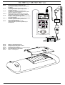
siehe Bild 8: Prüfung 3-phasiger Prüfobjekte unter Betriebsbedingung (isolierte Aufstellung
des Prüflings)
Hinweis zur Prüfung 3-phasiger Prüfobjekte unter Betriebsbedingung:
- Die Schutzleiterstrommessung erfolgt über einen Stromwandler im Schutzleiter des
Messadapters. Das Prüfobjekt ist isoliert aufzustellen. Kein Teil des Prüfobjektes darf eine
Verbindung zum Erdpotential haben. Ansonsten könnten Ableitströme gegen Erde das
Messergebiss beeinflussen.
- Eine Betätigung der Taste 7 ohne vorherigen Anschluss des Messadapters an das
BENNING ST 720 führt zu folgendem Warnhinweis im Display:
9. Instandhaltung
Vor dem Öffnen das BENNING ST 720 unbedingt spannungsfrei machen!
Elektrische Gefahr!
Die Arbeit am geöffneten BENNING ST 720 unter Spannung ist ausschließlich Elektrofachkräften vorbehalten, die dabei besondere Maßnahmen zur Unfallverhütung treffen müssen.
So machen Sie das BENNING ST 720 spannungsfrei, bevor Sie das Gerät öffnen:
- Schalten Sie das Prüfgerät aus
- Trennen Sie alle Anschlussleitungen vom Gerät
02/ 2011
BENNING ST 720
14
D
9.1 Sicherstellen des Gerätes
Unter bestimmten Voraussetzungen kann die Sicherheit im Umgang mit dem BENNING ST 720
nicht mehr gewährleistet sein; zum Beispiel bei:
- Sichtbaren Schäden am Gehäuse,
- Fehlern bei Messungen,
- Erkennbaren Folgen von längerer Lagerung unter unzulässigen Bedingungen und
- Erkennbaren Folgen von außerordentlicher Transportbeanspruchung.
In diesen Fällen ist das BENNING ST 720 sofort abzuschalten, von den Prüfstellen zu entfernen
und gegen erneute Nutzung zu sichern.
9.2 Reinigung
Reinigen Sie das Gehäuse äußerlich mit einem sauberen und trockenen Tuch (Ausnahme spezielle Reinigungstücher). Verwenden Sie keine Lösungs- und/ oder Scheuermittel, um das Gerät
zu reinigen. Achten Sie unbedingt darauf, dass das Batteriefach und die Batteriekontakte nicht
durch auslaufendes Batterie-Elektrolyt verunreinigt werden.
Falls Elektrolytverunreinigungen oder weiße Ablagerungen im Bereich der Batterie oder des Batteriegehäuses vorhanden sind, reinigen Sie auch diese mit einem trockenen Tuch.
9.3 Batteriewechsel
Vor dem Öffnen das BENNING ST 720 unbedingt spannungsfrei machen!
Elektrische Gefahr!
Das BENNING ST 720 wird durch sechs 1,5 V-Mignon-Batterien/Typ AA (IEC LR6) gespeist.
Ein Batteriewechsel ist erforderlich, wenn in der Anzeige 8 das Batteriesymbol erscheint.
So wechseln Sie die Batterien (siehe Bild 9):
- Schalten Sie das BENNING ST 720 aus.
- Legen Sie das BENNING ST 720 auf die Frontseite und lösen Sie die Schraube vom Batteriedeckel.
- Heben Sie den Batteriedeckel (im Bereich der Gehäusevertiefungen) vom Unterteil ab.
- Heben Sie die entladenen Batterien aus dem Batteriefach.
- Legen Sie dann die Batterien in die dafür vorgesehenen Stellen im Batteriefach (achten Sie
bitte unbedingt auf die korrekte Polung der Batterien).
- Rasten Sie den Batteriedeckel an das Unterteil an, und ziehen Sie die Schraube an.
siehe Bild 9:
Batterie-/ Sicherungswechsel
Leisten Sie Ihren Beitrag zum Umweltschutz! Batterien dürfen nicht in den
Hausmüll. Sie können bei einer Sammelstelle für Altbatterien bzw. Sondermüll
abgegeben werden. Informieren Sie sich bitte bei ihrer Kommune.
9.4Sicherungswechsel
Vor dem Öffnen das BENNING ST 720 unbedingt spannungsfrei machen!
Elektrische Gefahr!
Das BENNING ST 720 wird durch zwei eingebaute Sicherungen (16 A, 250 V, F, D = 5 mm, L =
20 mm), (10019440) vor Überlastung geschützt.
So wechseln Sie die Sicherungen (siehe Bild 9):
- Schalten Sie das BENNING ST 720 aus.
- Legen Sie das BENNING ST 720 auf die Frontseite und lösen Sie die Schraube vom
Batteriedeckel.
- Heben Sie den Batteriedeckel (im Bereich der Gehäusevertiefungen) vom Unterteil ab.
- Heben Sie ein Ende der defekten Sicherung seitlich mit einem Schlitzschraubendreher aus
dem Sicherungshalter.
- Entnehmen Sie die defekte Sicherung vollständig aus dem Sicherungshalter.
- Setzen Sie die neue Sicherung ein. Verwenden Sie nur Sicherungen mit gleichem Nennstrom,
gleicher Nennspannung, gleichem Trennvermögen, gleicher Auslösecharakteristik und
gleichen Abmessungen.
- Rasten Sie den Batteriedeckel an das Unterteil an, und ziehen Sie die Schraube an.
siehe Bild 9: Batterie-/Sicherungswechsel
9.5Kalibrierung
Um die angegebenen Genauigkeiten der Messergebnisse zu erhalten, muss das Gerät regelmäßig durch unseren Werksservice kalibriert werden. Wir empfehlen ein Kalibrierintervall von
einem Jahr. Senden Sie hierzu das Gerät an folgende Adresse:
Benning Elektrotechnik & Elektronik GmbH & Co. KG
Service Center
Robert-Bosch-Str. 20
D – 46397 Bocholt
9.6Ersatzteile
Sicherungen F 16 A, 250 V, Trennvermögen ≥ 500 A, D = 5 mm, L = 20 mm, T.Nr. 10019440
02/ 2011
BENNING ST 720
15
D
10.Umweltschutz
Bitte führen Sie das Gerät am Ende seiner Lebensdauer den zur Verfügung stehen
den Rückgabe- und Sammelsystemen zu.
02/ 2011
BENNING ST 720
16
Operating instructions
BENNING ST 720
Appliance tester for safety-related testing of portable electrical devices and equipment
- testing according to DIN VDE 0701-0702, ÖVE/ ÖNORM E 8701
- testing of cable reels, multiple distributors and IEC power cords
- tripping time measurement of RCDs
- voltage measurement on external shock-proof socket
Table of contents
1. User notes
2. Safety note
3. Scope of delivery
4. Unit description
5. General information
6. Ambient conditions
7. Electrical specifications
8. Measuring with the BENNING ST 720
9.Maintenance
10. Environmental note
1. User notes
These operating instructions are intended for
-
-
qualified electricians, competent persons and
electrotechnically trained persons
The BENNING ST 720 is intended for making measurements in dry environment (More details
in Section 6. “Ambient conditions”).
The following symbols are used in these operating instructions and on the BENNING ST 720:
Warning of electrical danger!
Indicates instructions which must be followed to avoid danger to persons.
Important, comply with the documentation!
The symbol indicates that the information provided in the operating instructions must
be complied with in order to avoid risks.
This symbol on the BENNING ST 720 means that the BENNING ST 720 complies
with the EU directives.
This symbol appears on the display to indicate discharged batteries. As soon as the
battery symbol flashes, immediately replace the batteries by new ones. Charged
batteries are also required for measuring in mains operating mode.
(AC) Alternating voltage or current.
Ground (Voltage against ground).
02/ 2011
protection class I
protection class II
BENNING ST 720
17
2. Safety note
The instrument is built and tested in accordance with
DIN VDE 0404 part 1 and 2
DIN VDE 0411 part 1/ EN 61010 part 1
DIN VDE 0413 part 1/ EN 61557 part 1, 2, 4 and 10
and has left the factory in perfectly safe technical state.
To maintain this state and ensure safe operation of the appliance tester, the user must observe
the notes and warnings given in these instructions at all times. Improper handling and nonobservance of the warnings might involve severe injuries or danger to life.
WARNING! Be careful when working with bare conductors or main line carrier!
Contact with live conductors will cause an electric shock!
The BENNING ST 720 may be used only in power circuits within the overvoltage
category II with a conductor for 300 V AC max. to earth.
Remember that work on electrical components of all kinds is dangerous. Even
low voltages of 30 V AC and 60 V DC may be dangerous to human life.
m
The device must be connected to a single-phase mains with 230 V, 50 Hz,
pre-fuse 16 A only. Please make sure not to exceed the maximum breaking
capacity/ lamp load of the test socket of the BENNING ST 720 (see chapters 7.4
and 7.5). Exceeding the values might cause tripping of the fuses and damaging
of the BENNING ST 720. Damages due to overload are excluded from possible
warranty claims.
m
Do not carry out repeated protective conductor or contact current
measurements with a measuring duration of 30 seconds at test objects with
high current consumption (16 A). Repeated measurements at maximum load
(16 A) might heat up the inside of the device and thus also its surface.
m
The protective conductor resistance measurement might be distorted by
impedances connected in parallel of additional operating circuits and by
transient currents.
Measurements of the protective conductor resistance and of the insulating
resistance must be carried out at idle system parts only.
Before starting the appliance tester up, always check it for signs of damage.
Should it appear that safe operation of the appliance tester is no longer possible, it should be
shut down immediately and secured to prevent it being switched on accidentally.
It may be assumed that safe operation is no longer possible:
- if the instrument show visible signs of damage
- if the appliance tester no longer functions
- after long periods of storage under unfavourable conditions
- after being subjected to rough transport
- the device is exposed to moisture.
In order to prevent danger
- do not touch the bare measuring probe tips of the measuring leads,
- plug the leads into the correspondingly marked jacks at the measuring
instrument
Maintenance:
Do not open the tester, because it contains no components which can be
repaired by the user. Repair and service must be carried out by qualified
personnel only!
Cleaning:
Regularly wipe the housing by means of a dry cloth and cleaning agent. Do not
use any polishing agents or solvents!
3. Scope of delivery
The scope of delivery for the BENNING ST 720 comprises:
3.1 One BENNING ST 720,
3.2 One test lead with alligator clip,
3.3 One IEC power cord (IEC adapter cable)
02/ 2011
BENNING ST 720
18
3.4 One mains connection cable
3.5 One compact protective pouch,
3.6 Six 1.5-V-batteries/ type AA (IEC LR6) fitted in the unit as initial equipment,
3.7 One operating manual
Parts subject to wear:
- The BENNING ST 720 is provided with two fuses for overload protection:
two fuses with a nominal current of 16 A, 250 V, F, breaking capacity ≥ 500 A, D = 5 mm, L =
20 mm (part no. 10019440)
- The BENNING ST 720 is supplied by six 1.5 V batteries/ type AA (IEC LR6).
Note on optional accessories:
- Test badges "next test", 300 pieces
- Measuring adapter for three-phase loads (passive, without mains voltage-dependent switching devices)
for RPE, RISO (insulating resistance) and IEA (alternative leakage current) measurements:
- 16 A CEE coupling - shock-proof plug (044122)
- 32 A CEE coupling - shock-proof plug (044123)
- Measuring adapter for three-phase loads (active, with mains voltage-dependent switching
devices)
for RPE and IPE measurements (direct measurement) under operating conditions:
- 16 A CEE adapter, three-phase, active (044140)
- 32 A CEE adapter, three-phase, active (044141)
As an alternative:
- BENNING CM 9 leakage current clamp for measuring the differential current, protective
conductor current and load current of single-phase and three-phase loads (044065)
- Measuring adapter for BENNING CM 9 leakage current clamp, conductors led through individually, with double insulation:
- 16 A shock-proof coupling - 16 A shock-proof plug (044131)
- 16 A CEE coupling - CEE plug (044127)
- 32 A CEE coupling - CEE plug (044128)
- Test certificate forms for "Testing of electrical devices" are available for download free of
charge at www.benning.de
4. Unit description
See figure 1:
Appliance front face
See figure 2:
Top side of the device
The display and operator control elements specified in Fig. 1 and 2 are designated as follows:
1 test socket, for connecting the device to be tested,
2
-key, testing of devices of protection class I (devices with protective conductor and accessible conductive parts which are connected to the protective conductor),
3
-key, testing of devices of protection class II (shock-proof devices without protective conductor and with accessible conductive parts) and testing of devices of protection class III
(safety extra-low voltage),
4
-key, testing the protective conductor current (differential measurement) or contact current
(direct measurement) under operating conditions (test sample is supplied with mains voltage)
5
-key, reducing the testing voltage to 250 VDC or 500 VDC for measuring the insulating
resistance
6
-key, testing of 30 mA RCDs
7
-key, testing of three-phase devices under operating conditions
8 Digital display, indicates the test progress and individual measuring results,
9 4 mm test socket, for connecting the test lead with alligator clip
J IEC connector, for connecting the IEC power cord
K Mains connection socket, for connecting the mains voltage (230 V, 50 Hz), for voltage
measurement at external shock-proof socket or for connecting the measuring signal cable
of the measuring adapter (16 A CEE adapter, three-phase, active/ 32 A CEE adapter, threephase, active)
5. General information
The BENNING ST 720 is intended for electrical safety tests according to DIN VDE 0701-0702,
BGV A3 and ÖVE/ ÖNORM E8701.
Automatically, the BENNING ST 720 verifies the type of the connected test object and informs
the user in case of incorrect selection of the testing procedure [2...3]: preset limiting values and
measuring results with "pass/ fail" information make it easier to evaluate the test.
- At full battery capacity, the BENNING ST 720 allows to carry out approx. 2,500 device tests.
6.
-
-
-
-
-
Ambient conditions
The BENNING ST 720 is intended for making measurements in dry environment.
Maximum barometric elevation for making measurements: 2000 m,
Over voltage category/ setting category: IEC 61010-1 → 300 V category II,
Contamination class: 2,
Protection class: IP 40 (DIN VDE 0470-1 IEC/ EN 60529)
02/ 2011
BENNING ST 720
19
-
-
-
IP 40 means: Protection against access to dangerous parts and protection against solid impurities of a diameter > 1 mm, (4 - first index). No protection against water, (0 - second index).
EMC: EN 61326-1
Operating temperature and relative humidity:
For operating temperatures from 0 °C to 30 °C: relative humidity less than 80 %
For operating temperatures from 31 °C to 40 °C: relative humidity less than 75 %
Storage temperature: The BENNING ST 720 can be stored at any temperature within the
range of - 25 °C to + 65 °C (relative humidity from 0 to 80 %). The battery should be removed
from the instrument for storage.
7. Electrical specifications
Note: The measuring accuracy is specified as the sum of
- a relative fraction of the measured value and
- a number of digits (i.e. counting steps of the last digit).
This specified measuring accuracy is valid for temperatures within the range of 18 °C to 28 °C
and relative humidity lower than 80 %.
7.1 Protective conductor resistance
Measuring range
Resolution
0.05 Ω - 19.99 Ω
0.01 Ω
Measuring accuracy
5 % ± 2 digits
Testing current:
> 200 mA (2 Ω)
open-circuit voltage:
4V-9V
Preset limiting value:
0.3 Ω
7.2 Insulating resistance
Measuring range
Resolution
Measuring accuracy
0.1 MΩ - 19.99 MΩ
0.01 MΩ
5 % ± 2 digits
Testing voltage:
250 VDC/ 500 VDC, + 20 %, - 0 %
Testing current:
> 1 mA, < 2 mA at 2 kΩ
Preset limiting value:
1 MΩ (protection class I), 2 MΩ (protection class II)
7.3Protective conductor current and contact current by means of alternative leakage
current measurement method
Measuring range
Resolution
0.25 mA - 19.99 mA
0.01 mA
Testing voltage:
Measuring accuracy
5 % ± 2 digits
40 VAC, 50 Hz
Testing current:
< 10 mA at 2 kΩ
Preset limiting value:
3.5 mA (protection class I), 0.5 mA (protection class II)
7.4 Protective conductor current (differential current measurement method)
Measuring range
Resolution
Measuring accuracy
0.25 mA - 19.99 mA
0.01 mA
5 % ± 2 digits
Nominal voltage:
230 V ± 10 % (as mains feed-in)
Rated current:
16 A
Max. breaking capacity:
3000 VA
Max. lamp load:
1000 W
Max. measuring duration:
30 seconds
Preset limiting value:
3.5 mA (protection class I)
Resistance to external
voltages:
max. 276 V
For non-sinusoidal current supply, an additional error has to be considered:
crest factor of > 1.4 to 2.0, additional error + 0.4 %
External magnetic fields might influence the measuring result additionally.
02/ 2011
BENNING ST 720
20
7.5 Contact current (direct measurement method)
Measuring range
Resolution
Measuring accuracy
0.1 mA - 1.99 mA
0.01 mA
5 % ± 2 digits
Nominal voltage:
230 V ± 10 % (as mains feed-in)
Rated current:
16 A
Max. breaking capacity:
3000 VA
Max. lamp load:
1000 W
Max. measuring duration:
30 seconds
Preset limiting value:
0.5 mA (protection class II)
Resistance to external
voltages:
max. 276 V
For non-sinusoidal current supply, an additional error has to be considered:
crest factor of > 1.4 to 2.0, additional error + 3.1 %
7.6 Cord test
- measurement of the protective conductor resistance according to 7.1
- measurement of the insulating resistance according to 7.2
- line break testing of the external conductor (L) and the neutral conductor (N)
- short-circuit testing of the external conductor (L) and the neutral conductor (N)
7.7 Tripping time measurement of RCDs
Measuring range
Resolution
Measuring accuracy
10 ms - 500 ms
1 ms
5 % ± 2 digits
Testing current/ polarity:
30 mA sinusoidal/ 0° and 180°
Preset limiting value:
200 ms
7.8Protective conductor current (direct measurement method) of three-phase test objects under operating conditions
Measuring range
Resolution
Measuring accuracy
0.25 mA - 9.99 mA
0.01 mA
5 % ± 2 digits
Nominal voltage:
3 x 400 V ± 10 % (as mains feed-in)
Rated current:
16 A respectively 32 A
Preset limiting value:
3.5 mA
7.9 Voltage measuring on external shock-proof socket
Measuring range
Resolution
Measuring accuracy
Overload protection
50 V - 270 VAC
1V
5 % ± 2 Digit
300 V
Display:
- voltage between the external conductor (L) and the neutral conductor (N)
- voltage between the external conductor (L) and the ground conductor (PE)
- voltage between the neutral conductor (N) and the ground conductor (PE)
7.10 Limiting values according to DIN VDE 0701-0702 and ÖVE/ ÖNORM E 8701-1
Note:
Limiting values preset in bold are stored in the BENNING ST 720.
Protection class I
Protective conductor resistance
RPE
02/ 2011
Protection class II, III
for cords with rated current ≤ 16 A:
≤ 0.3 Ω up to a length of 5 m,
per further 7.5 m:
additional 0.1 Ω, max. 1 Ω,
For cords with higher rated currents
the calculated ohmic resistance value
applies.
BENNING ST 720
Line test
≤ 0.3 Ω
(see protection class I)
21
Insulating
resistance
RISO
Protective conductor current
IEA/ ILEAK
Contact current
IEA/ ILEAK
≥ 1 MΩ
≥ 2 MΩ for proving safe
disconnection (transformer)
≥ 0.3 MΩ for devices with heating
element
≥ 2 MΩ
(protection class II),
≥ 0.25 MΩ
(protection class III),
≥ 1 MΩ
≤ 3.5 mA
on conductive parts with
PE connection
1 mA/ kW for devices with heating
elements P > 3.5 kW
≤ 0.5 mA
on conductive parts without
PE connection
≤ 0.5 mA
on conductive parts
without PE connection
8. Measuring with the BENNING ST 720
8.1 Preparations for measuring
Operate and store the BENNING ST 720 only at the specified storage and operating temperatures
conditions. Do not permanently expose the device to sunlight.
- Check rated voltage and rated current details specified on the safety measuring leads.
- Strong sources of interference in the vicinity of the BENNING ST 720 might lead to unstable
readings and measuring errors.
Before starting the BENNING ST 720, always check the device, the lines and the
test object for damages.
Please make sure not to exceed the maximum breaking capacity/ lamp load of
the test socket of the BENNING ST 720 (see chapters 7.4 and 7.5). Exceeding
the values might cause tripping of the fuses and damaging of the BENNING
ST 720. Damages due to overload are excluded from possible warranty claims.
The plug of the mains connection cable can be connected with the socket K
of the BENNING ST 720 in one position only (see white mark). Do not exert
force to the plug of the mains connection cable in order to avoid damaging of
the BENNING ST 720.
Before starting the test, switch the test object on (mains switch ON).
If the BENNING ST 720 is connected to the mains voltage, the test object will
be supplied with mains voltage during the protective conductor/ contact current
measurement. During measurement, check the test object for proper functioning!
At the beginning of the test it has to be checked whether the selected testing
procedure complies with the protection class of the connected test object.
8.1.1 Switching the BENNING ST 720 ON/ OFF
- Press and hold the keys 2 and 3 for approx. 3 seconds to switch the BENNING ST 720 on.
Acoustic signals confirm that the device is switched on. Press the keys again to switch the
device off.
-
After approx. 2 minutes, the BENNING ST 720 switches off automatically (APO, Auto
Power-Off). It switches on again when the keys 2 and 3 are pressed. An acoustic signal
indicates that the device has switched off automatically.
8.1.2 Testing the mains voltage on external shock-proof socket
- Connect the mains connection cable to the mains connection socket K of the BENNING ST 720.
- Connect the shock-proof plug to the shock-proof socket to be tested. With the mains voltage
being applied, the voltage measurement will start automatically.
- Depending on the external conductor position (right or left) of the shock-proof socket, the
02/ 2011
BENNING ST 720
22
voltage potentials between the connecting terminals L, N and PE will be shown on the display for approx. 3 seconds.
or
-
If the voltage potentials are within the following limiting values, there will be a
"LN", "LE" and "NE" symbols.
LN
195 V - 253 V
LE
195 V - 253 V
NE
< 30 V
LN
or
next to the
195 V - 253 V
LE
< 30 V
NE
195 V - 253 V
Only the voltage potentials between the individual connections L, N and PE are
measured. The measurement does not provide any information on the proper
installation of the shock-proof socket. There will be no warning in case of a
dangerous contact voltage of the PE conductor!
The BENNING ST 720 must not be permanently connected to the mains voltage!
- After approx. 3 seconds, the BENNING ST 720 automatically switches to stand-by mode.
See figure 3:
Voltage measurement on external shock-proof socket
8.1.3 Testing procedure
The BENNING ST 720 is intended for electrical safety tests according to DIN VDE 0701-0702
and ÖVE/ ÖNORM E 8701. Please refer to the current version of the standards for detailed
information concerning the tests and limiting values.
Automatically, the BENNING ST 720 verifies the type of the connected test object and informs
the user in case of incorrect preselection of the testing procedure [2...3].
Note:
- The BENNING ST 720 can be used for tests in battery operating mode and in mains operating mode with connection of a mains voltage of 230 V. In battery operating mode, it has
to be observed that the protective conductor current and contact current measurement is
carried out by means of the alternative leakage current measurement method. This method
is appropriate for test objects which do not contain any mains voltage-dependent switching
elements (e.g. mains supply units).
- If the internal structure of the test object is not known or if it contains mains voltage-dependent switching elements, the test has to be carried out in mains operating mode with connection of a mains voltage of 230 V. As soon as the BENNING ST 720 is supplied with mains
voltage via the jack K, the protective conductor current/ contact current measurement will
be carried out automatically by means of the differential current/ direct measurement method
under operating conditions of the test object.
- The testing voltage for insulating resistance measurement is preset to 500 VDC according
to the applicable standard. For test objects with integrated overvoltage arresters and for
electronic devices for which there are objections regarding a testing voltage of 500 VDC, the
testing voltage can be reduced to 250 VDC by means of the
-key 5.
8.2 Testing of electrical devices / equipment according to DIN VDE 0701-0702 and ÖVE/
ÖNORM E 8701
Prior to test, a visual inspection of the test object has to be carried out. In case
of possible damages, the test must be stopped.
8.2.1 Testing of devices of protection class I
Testing of devices with protective conductor and accessible conductive parts which are connected to the protective conductor.
- Connect the test object to the test socket 1 of the BENNING ST 720.
- Plug the 4 mm safety plug of the test lead with alligator clip into the 4 mm safety socket 9
and establish a connection with a metal part of the test object.
- For mains operating mode (protective conductor current by means of differential current
measurement method, test object in operation!): Connect the plug of the mains connection cable with the socket K and the shock-proof plug with a protected shock-proof socket
(230 V, 50 Hz, 16 A).
02/ 2011
BENNING ST 720
23
- If necessary, the testing voltage of the RISO (insulating resistance) measurement can be
reduced to 250 VDC by means of the
-key 5. The selected testing voltage is briefly shown
on the display 8. Press the key again to switch back to the preset testing voltage of 500 VDC.
- Switch the test object on.
- Press the
-key 2 to start the automatic testing procedure.
- The test starts with measuring the protective conductor resistance RPE. If RPE is higher than
the admissible limiting value, the measured value of RPE will be shown on the display and
a
will appear next to the RPE symbol. "FAIL" appears on the display to confirm that the
measurement has been stopped.
-
If RPE is lower than the admissible limiting value, the measured value of RPE is shown and
a
appears next to the RPE symbol. Now, the RPE measurement is carried out again with
reversed polarity and the highest measured value of both measurements will be displayed.
After the RPE test has been passed, the test of the insulating resistance is started.
-
If "Lo LOAD" is shown on the display, please check whether the test object is switched on.
-
Press the key 2 to continue the testing procedure in case of the load being too low (RL-N
> 6 kΩ).
If "HIGH LOAD“ is shown on the display, this indicates an excessive load (RL-N << 14 Ω,
ILAST (ILOAD) > 16 A) of the test object. There might be danger of a short-circuit or of an earth
fault. Check whether there is a short-circuit between the external conductor (L) and neutral
conductor (N) of the test object.
If there is no short-circuit, you can continue with the testing procedure by pressing the key 2.
If the insulating resistance RISO is higher than the admissible limiting value, a
appears
next to the RISO symbol.
-
-
-
BENNING ST 720 in mains operating mode:
- The BENNING ST 720 interrupts the testing procedure after the RISO (insulating resistance)
measurement and requests the user to switch the mains voltage of 230 V to the test socket
1 by showing a flashing "ILEAK" symbol. Make sure that the test sample is protected and
press the
key 4 to measure the protective conductor current by means of the differential
current measurement method.
- The protective conductor current measurement (differential current measurement method)
only starts as soon as the mains voltage is correct applied.
02/ 2011
BENNING ST 720
24
step 1 of 2:
-
After a measuring time of 5 seconds or by pressing the key 4, mains polarity will be reversed
and the protective conductor current will be measured with reversed mains voltage ("L/N" "N/L"). The highest measured value of both measurements will be displayed. (step 2 of 2)
step 2 of 2:
-
-
If the protective conductor current is lower than the admissible limiting value, a
shown next to the ILEAK symbol.
The overall test is considered to be passed, if "PASS" is shown on the display.
will be
As an alternative:
BENNING ST 720 in battery operating mode (without mains supply):
- Similarly, a
will be shown next to the IEA symbol, if the protective conductor current IEA (alternative leakage current measurement method) is lower than the admissible limiting value.
- The test is considered to be passed, if "PASS" is shown on the display.
See figure 4:
Testing of devices of protection class I (devices with protective conductor and accessible conductive parts which are connected to the protective
conductor)
Note on measuring the protective conductor resistance:
-
Alternatively, the measurement of the protective conductor resistance RPE can be carried out as permanent measurement (max. 4 minutes). For this purpose press the key
2 for approx. > 5 seconds until the symbol appears on the display. Check the connecting line of the test object by bending it over the entire length in order to detect
weak points or a break of the protective conductor. The BENNING ST 720 continuously
records the current measured value on the display and stores the maximum value in the
memory. By pressing the key 2 again, the measurement is carried out with reversed
polarity. Press the key 2 again to indicate the maximum value of RPE on the display and
to continue the testing procedure as described in section 8.2.1.
Note on measuring the protective conductor current in mains operating mode:
- Alternatively, the measurement of the protective conductor current ILEAK can be carried out
as permanent measurement (max. 30 seconds). Press the key 4 for approx. > 5 seconds
to start permanent measurement. After 30 seconds, the polarity of the mains voltage will be
reversed automatically ("L/N" - "N/L"). By pressing the key 4 earlier, the mains voltage polarity reversal can be activated manually and by pressing the key 4 again, the measurement
can be stopped.
Note on measuring the contact current:
- Accessible conductive parts which are not connected with the protective conductor have to
be tested as described in section 8.2.2. For measuring the contact current (direct measurement method), the BENNING ST 720 has to be operated with a mains voltage of 230 V.
- During contact current measurement by means of the direct measurement method, no part
of the test object must have a connection to the earth potential. The test object must be
02/ 2011
BENNING ST 720
25
placed onto an insulated surface. Otherwise, leakage currents to earth might influence the
measuring result.
8.2.2
Testing of devices of protection class II (shock-proof) and of devices of protection class III K (safety extra-low voltage)
Testing of devices without protective conductor and with accessible conductive parts
- Connect the test object to the test socket 1 of the BENNING ST 720.
- Establish a connection between the 4 mm test socket 9 and a metal part of the test object
by means of the test lead with alligator clip.
- For mains operating mode (contact current by means of the direct measurement method,
test object in operation!): Connect the plug of the mains connection cable with the socket K
and the shock-proof plug with a protected shock-proof socket (230 V, 50 Hz, 16 A).
- If necessary, the testing voltage of the RISO (insulating resistance) measurement can be
reduced to 250 VDC by means of the
-key 5. The selected testing voltage is briefly shown
on the display 8. Press the key again to switch back to the preset testing voltage of 500 VDC.
-
-
-
Switch the test object on.
Press the
key 3 to start the automatic testing procedure.
If "Lo LOAD" is shown on the display, please check whether the test object is switched on.
-
Press the key 3 to continue the testing procedure in case of the load being too low (RL-N
> 6 kΩ).
If "HIGH LOAD“ is shown on the display, this indicates an excessive load (RL-N << 14 Ω,
ILAST (ILOAD) > 16 A) of the test object. There might be danger of a short-circuit or of an earth
fault. Check whether there is a short-circuit between the external conductor (L) and neutral
conductor (N) of the test object.
If there is no short-circuit, you can continue with the testing procedure by pressing the
-key 3.
If the insulating resistance RISO is higher than the admissible limiting value, a
appears
next to the RISO symbol.
-
-
-
BENNING ST 720 in mains operating mode:
- The BENNING ST 720 interrupts the testing procedure after the RISO (insulating resistance)
measurement and requests the user to switch the mains voltage of 230 V to the test socket
1 by showing a flashing "ILEAK" symbol. - Make sure that the test sample is protected and
press the
-key 4 to measure the contact current ILEAK (direct measurement method).
- The contact current by means of the direct measurement method only starts as soon as the
mains voltage is correct applied.
step 1 of 2:
-
After a measuring time of 5 seconds or by pressing the key 4, mains polarity will be reversed and the contact current will be measured with reversed mains voltage ("L/N" - "N/L").
The highest measured value of both measurements will be displayed. (step 2 of 2)
02/ 2011
BENNING ST 720
26
step 2 of 2:
-
-
If the contact current is lower than the admissible limiting value, a
will be shown next to
the ILEAK symbol.
The overall test is considered to be passed, if "PASS" is shown on the display.
As an alternative:
BENNING ST 720 in battery operating mode (without mains supply):
- Similarly, a
will be shown next to the IEA symbol, if the contact current IEA (alternative
leakage current measurement method) is lower than the admissible limiting value.
- The test is considered to be passed, if "PASS" is shown on the display.
See figure 5:
Testing of devices of protection class II (shock-proof devices without protective conductor and with accessible conductive parts) and testing of devices of protection class III (safety extra-low voltage)
Note on measuring the contact current in mains operating mode:
- During contact current measurement by means of the direct measurement method, no part
of the test object must have a connection to the earth potential. The test object must be
placed onto an insulated surface. Otherwise, leakage currents to earth might influence the
measuring result.
- Alternatively, the measurement of the contact current ILEAK can be carried out as permanent
measurement (max. 30 seconds). Press the key 4 for approx. > 5 seconds to start permanent measurement. After 30 seconds, the polarity of the mains voltage will be reversed
automatically ("L/N" - "N/L"). By pressing the key 4 earlier, the mains voltage polarity reversal can be activated manually and by pressing the key 4 again, the measurement can be
stopped.
Note on measuring the insulating resistance for test objects of protection class III:
- Due to the preset limiting value of 2 MΩ for test objects of protection class II, for the testing
of test objects of protection class III it has to be observed that measured values between
the limiting values of 2 MΩ (protection class II) and up to 0.25 MΩ (protection class III) are
indicated with a
next to the RISO symbol. In this case, the measured value has to be
evaluated by a competent person.
8.2.3 Cord test
The cord test can be used both for the testing of IEC power cords (device connecting cables
with IEC coupler) and for the testing of cable reels, multiple distributors and extension cables.
8.2.3.1 Testing of IEC power cords (IEC adapter cables)
- Disconnect the plug of the mains connection cable from the socket K of the BENNING ST 720.
- Connect the IEC power cord to be tested to the BENNING ST 720 by means of the IEC connector J.
- Press the
key 2 to start the automatic testing procedure.
- The test starts with measuring the protective conductor resistance RPE.
- Depending on whether the value is higher or lower than the limiting value, a
or a
is
indicated next to the RPE symbol.
-
The protective conductor resistance depends on the length and cross-section
of the line to be tested. It is possible that the measuring result is acceptable
although the BENNING ST 720 indicates a
next to the RPE symbol.
Please refer to Table 1 for typical resistance values of lines.
02/ 2011
BENNING ST 720
27
Cross-section
Length
1.0 mm²
1.5 mm²
2.5 mm²
5m
0.1 Ω
0.06 Ω
0.04 Ω
10 m
0.2 Ω
0.12 Ω
0.08 Ω
25 m
0.5 Ω
0.3 Ω
0.2 Ω
50 m
1.0 Ω
0.6 Ω
0.4 Ω
Table 1:Resistance values of the protective conductor depending on length and cross-section
-
-
-
-
After the RPE test has been passed, the measurement of the insulating resistance is carried
out automatically.
Depending on whether the value is higher or lower than the limiting value, a
or a
is
indicated next to the RISO symbol.
After the RISO test has been passed, the external conductor (L) and the neutral conductor
(N) are checked for line breaks and short-circuits. A passed test regarding line breaks and
short-circuits is indicated by a
next to the
and the "Good“ symbol.
The "PASS" symbol confirms successful testing of the entire testing procedure.
-
If the test regarding line breaks and short-circuits has failed, one of the following symbols is
indicated instead of the "Good" symbol:
- "OPEN" symbol:
confirms a line break of the external conductor (L) or neutral conductor (N)
- "Shor" symbol:
confirms a short-circuit between the external conductor (L) and the neutral conductor
(N)
See figure 6a: Testing of device connecting cables with IEC connector
Note on measuring the protective conductor resistance:
-
Alternatively, the measurement of the protective conductor resistance RPE can be carried out as permanent measurement (max. 3 minutes). For this purpose press the key
2 for approx. > 5 seconds until the symbol appears on the display. Check the connecting line of the test object by bending it over the entire length in order to detect
weak points or a break of the protective conductor. The BENNING ST 720 continuously
records the current measured value on the display and stores the maximum value in the
memory. By pressing the key 2 again, the measurement is carried out with reversed
polarity. Press the key 2 again to indicate the maximum value of RPE on the display and
to continue the testing procedure as described in section 8.2.3.1.
8.2.3.2 Testing of cable reels, multiple distributors and extension cables
- Disconnect the plug of the mains connection cable from the socket K of the BENNING ST 720.
- Connect the IEC power cord (IEC adapter cable) included in the scope of delivery to the IEC
connector J of the BENNING ST 720.
- Connect the line to be tested to the test socket 1 and to the shock-proof socket of the IEC
power cord.
- Press the key 2 to start the automatic testing procedure.
- The further testing procedure corresponds to the testing procedure described in section
8.2.3.1.
See figure 6b: Testing of lines, multiple distributors and cable reels
8.3 Testing RCDs with a nominal fault current of 30 mA
- Connect the mains connection cable to the mains connection socket K of the BENNING ST 720.
- Make sure to connect the shock-proof plug with a shock-proof socket which is protected by
the RCD to be tested. With the mains voltage being applied, the voltage measurement will
start automatically.
- Depending on the external conductor position (right or left) of the shock-proof socket, the
voltage potentials between the connecting terminals L, N and PE will be shown on the display for approx. 2 seconds.
02/ 2011
BENNING ST 720
28
or
-
-
-
-
With correct mains voltage ("LN" and "LE" symbols on the display), press the
start the RCD test.
-key 6 to
LN
LE
NE
Mains voltage
Flashing
Flashing
OFF
No mains voltage
OFF
Flashing
Flashing
Earth fault
The BENNING ST 720 generates a fault current of 30 mA with positive (0°) or negative
(180°) initial polarity. The RCD will be tripped and the tripping time will be measured.
If the tripping time is less than the limiting value (200 ms), a
will be shown next to the
tripping time.
The test is considered to be passed, if "PASS" is shown on the display.
- Repeat the test with reversed initial polarity.
See figure 7:
Testing of RCD (IΔN 30 mA)
Note:
- By generating a fault current of 30 mA, it is proven that the RCD will trip when the nominal
fault current is reached. If the limiting value of the maximum contact voltage of 50 V is exceeded, the "UB > 50 V" symbol will be shown on the display and the testing will be stopped.
- When testing mobile RCDs, make sure that the mobile RCD is connected with a shock-proof
socket which is not protected by an own RCD.
c
Measurement might be influenced by:
- a possibly existing voltage between the protective conductor of the shockproof socket and earth
- leakage currents in the circuit behind the RCD
- further earthing equipment
- equipment which is connected behind the RCD and which will cause a
longer tripping time, e.g. capacitors or rotating machines
8.4 Testing three-phase test objects under operating conditions
Three-phase test objects are tested by means of the optional measuring adapters 16 A CEE,
three-phase, active (044140) or 32 A CEE, three-phase, active (044141).
- Connect the CEE plug of the test object with the CEE coupling of the measuring adapter and
connect the CEE plug of the measuring adapter to a protected supply mains (3 x 400 V, N,
PE, 50 Hz, 16 A/ 32 A).
- Connect the measuring signal cable of the measuring adapter with the mains connection
socket K of the BENNING ST 720.
- Connect the 4 mm safety plug of the test lead with alligator clip with the 4 mm safety socket
9 of the BENNING ST 720 and establish a connection with a metal part of the test object.
- Make sure that the test sample is protected and switch it on.
- Press the
key 7 to start the automatic testing procedure.
- If a contact voltage is applied to the metal part of the test object, measurement will be interrupted and the following warning will be shown on the display:
02/ 2011
BENNING ST 720
29
-
-
-
-
Otherwise, the measurement of the protective conductor resistance (RPE) will be started with
automatic polarity reversal and the highest measured value of both measurements will be
shown on the display.
After the RPE test has been passed, the test of the protective conductor current ILEAK will be
carried out as permanent measurement for max. 30 seconds. Press the
key 7 to finish
early the measurement.
If the protective conductor current is lower than the admissible limiting value, a
shown next to the ILEAK symbol.
The overall test is considered to be passed, if "PASS" is shown on the display.
See figure 8:
will be
Testing three-phase test objects under operating conditions (test sample
placed on insulated surface)
Note on testing three-phase test objects under operating conditions:
- The protective conductor current measurement will be carried out by means of a current
transformer in the protective conductor of the measuring adapter. The test object must be
placed onto an insulated surface. No part of the test object must have a connection to the
earth potential. Otherwise, leakage currents to earth might influence the measuring result.
- When pressing the key 7 without previously connecting the measuring adapter to the BENNING ST 720, the following warning will be shown on the display:
9.Maintenance
Before opening the BENNING ST 720, make sure that it is free of voltage!
Electrical danger!
Work on the opened BENNING ST 720 under voltage must be carried out by skilled electricians with special precautions for the prevention of accidents only!
Make sure that the BENNING ST 720 is free of voltage as described below before opening the
instrument:
02/ 2011
BENNING ST 720
30
-
-
Switch the tester off.
Remove all connecting cables from the object.
9.1 Securing the instrument
Under certain circumstances safe operation of the BENNING ST 720 is no longer ensured, for
example in the case of:
- Visible damage of the casing.
- Incorrect measurement results.
- Recognisable consequences of prolonged storage under improper conditions.
- Recognisable consequences of extraordinary transportation stress.
In such cases the BENNING ST 720 must be switched off immediately, disconnected from the
measuring points and secured to prevent further utilisation.
9.2Cleaning
Clean the exterior of the housing with a clean dry cloth (exception: special cleaning wipers).
Avoid using solvents and/ or scouring agents for cleaning the instrument. It is important to make
sure that the battery compartment and battery contacts are not contaminated by leaking electrolyte.
If electrolyte contamination or white deposits occur in the area of the batteries or battery compartment, clean them too with a dry cloth.
9.3 Battery replacement
Before opening the BENNING ST 720, make sure that it is free of voltage!
Electrical danger!
The BENNING ST 720 is supplied by means of six 1.5 V batteries/ type AA (IEC LR6).
A battery replacement (see Figure 9) is required, if the battery symbol appears on the display
unit 8.
Proceed as follows to replace the batteries:
- Switch the BENNING ST 720 off.
- Put the BENNING ST 720 face down and unscrew the screw of the battery compartment cover.
- Lift off the battery compartment cover (in the area of the housing slots) from the bottom part
of the battery compartment.
- Remove the discharged batteries from the battery compartment.
- Then, insert the new batteries into the battery compartment at the provided places (please
observe correct polarity of the batteries).
- Lock the battery compartment cover into place on the bottom part and tighten the screw.
See figure 9:
Battery/ fuse replacement
m
Make your contribution to environmental protection! Do not dispose of
discharged batteries in the household garbage. Instead, take them to a
collecting point for discharged batteries and special waste material. Please
inform yourself in your community.
9.4 Fuse replacement
Before opening the BENNING ST 720, make sure that it is free of voltage!
Electrical danger!
The BENNING ST 720 is protected against overload by means of two built-in fuses (16 A, 250 V,
F, D = 5 mm, L = 20 mm) (10019440).
Proceed as follows to replace the fuse (see Figure 9):
- Switch the BENNING ST 720 off.
- Put the BENNING ST 720 face down and unscrew the screw of the battery compartment cover.
- Lift off the battery compartment cover (in the area of the housing slots) from the bottom part
of the battery compartment.
- Laterally lift one side of the defective fuse off the fuse holder by means of a slotted screwdriver.
- Completely remove the defective fuse from the fuse holder.
- Insert the new fuse. Only use fuses of the same nominal current, nominal voltage, nominal
breaking capacity, tripping characteristic and dimensions.
- Lock the battery compartment cover into place on the bottom part and tighten the screw.
See figure 9:
Battery/ fuse replacement
9.5Calibration
To maintain the specified accuracy of the measurement results, the instrument must be recalibrated at regular intervals by our factory service. We recommend a recalibration interval of one
year. Send the appliance to the following address:
BENNING Elektrotechnik & Elektronik GmbH & Co. KG
Service Centre
Robert-Bosch-Str. 20
D - 46397 Bocholt
02/ 2011
BENNING ST 720
31
9.6 Spare parts
Fuses F 16 A, 250 V, breaking capacity ≥ 500 A, D = 5 mm, L = 20 mm, part no. 10019440
10. Environmental note
At the end of the product’s useful life, please dispose of the device at collection
points provided in your community.
02/ 2011
BENNING ST 720
32
Benning Elektrotechnik & Elektronik GmbH & Co. KG
Münsterstraße 135 - 137
D - 46397 Bocholt
Phone: +49 (0) 2871 - 93 - 0 • Fax: +49 (0) 2871 - 93 - 429
www.benning.de • E-Mail: [email protected]