1
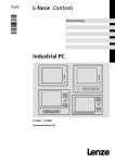
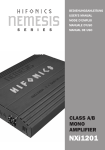
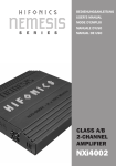
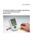
deutsch / english PP50 DSP PLUG & PLAY 5-Kanal Verstärker mit integriertem DSP 5-Channel Amplifier with integrated DSP Herzlichen Glückwunsch! Sehr geehrter Kunde, Wir gratulieren Ihnen zum Kauf dieser hochwertigen HELIX-Endstufe. HELIX setzt mit der PP50 DSP neue Maßstäbe im aufstrebenden Plug & Play Markt. Dabei profitieren Sie als Kunde direkt von unserer nahezu 30 jährigen Erfahrung in der Forschung und Entwicklung von Audiokomponenten. Dieser Plug & Play-Verstärker wurde von uns nach neuesten technischen Erkenntnissen entwickelt und zeichnet sich durch hervorragende Verarbeitung und eine überzeugende Anwendung ausgereifter Technologien aus. Viel Freude an diesem Produkt wünscht Ihnen das Team von AUDIOTEC FISCHER Allgemeine Hinweise Allgemeines zum Einbau von HELIX-Komponenten Um alle Möglichkeiten des Produktes optimal ausschöpfen zu können, lesen Sie bitte sorgfältig die nachfolgenden Installationshinweise. Wir garantieren, dass jedes Gerät vor Versand auf seinen einwandfreien Zustand überprüft wurde. Vor Beginn der Installation unterbrechen Sie den Minusanschluss der Autobatterie. Wir empfehlen Ihnen, die Installation von einem Einbauspezialisten vornehmen zu lassen, da der Nachweis eines fachgerechten Einbaus und Anschlusses des Gerätes Voraussetzung für die Garantieleistungen sind. Installieren Sie Ihren PP50 DSP Verstärker an einer trockenen Stelle im Auto und vergewissern Sie sich, dass der Verstärker am Montageort genügend Kühlung erhält. Montieren Sie das Gerät nicht in zu kleine, abgeschlossene Gehäuse ohne Luftzirkulation oder in der Nähe von wärmeabstrahlenden Teilen oder elektronischen Steuerungen des Fahrzeuges. Im Sinne der Unfallsicherheit muss der Verstärker professionell befestigt werden. Dieses geschieht über Schrauben, die in eine Montagefläche eingeschraubt werden, die wiederum genügend Halt bieten muss. Bevor Sie die Schrauben im Montagefeld befestigen, vergewissern Sie sich, dass keine elektrischen Kabel und Komponenten, hydraulische 2 Bremsleitungen, der Benzintank etc. dahinter verborgen sind. Diese könnten sonst beschädigt werden. Achten Sie bitte darauf, dass sich solche Teile auch in der doppelten Wandverkleidung verbergen können. Allgemeines zum Anschluss des PP50 DSP Verstärkers Der PP50 DSP Verstärker darf nur in Kraftfahrzeuge eingebaut werden, die den 12V-Minuspol an Masse haben. Bei anderen Systemen kann die HELIX PP50 DSP und die elektrische Anlage des Kfz beschädigt werden. Verwenden Sie zur Verbindung der HELIX PP50 DSP mit dem Autoradio ausschließlich das beiliegende HELIX-Anschlusskabel! Die Verwendung eines anderen Kabels kann zu Schäden an ihrer Anlage führen. Die Sicherung am Anschlusskabel darf nur mit dem gleichen Wert (20A) ersetzt werden, um eine Beschädigung des Gerätes zu verhindern. Höhere Werte können zu gefährlichen Folgeschäden führen. Die Kabelverbindungen müssen so verlegt sein, dass keine Klemm-, Quetsch- oder Bruchgefahr besteht. Bei scharfen Kanten (Blechdurchführungen) müssen alle Kabel gegen Durchscheuern gepolstert sein. Ferner darf das Versorgungskabel niemals mit Zuleitungen zu Vorrichtungen des Kfz (Lüftermotoren, Brandkontrollmodulen, Benzinleitungen etc.) verlegt werden. Anschluss- und Bedienelemente 1 2 3 4 1 Subwoofer-Ausgang 4 Zum Anschluss eines passiven Plug & Play Subwoofers 2 AUX-Eingang 5 3,5mm Klinkenbuchse zum Anschluss von z.B. Navi, Telefon, iPod etc. 5 HELIX Plug & Play Connector Verwenden Sie nur das HELIX Originalkabel zum Anschluss der PP50 DSP Remote Der Remote-Anschluss kann sowohl als Ein- oder Ausgang benutzt werden 3 AUX Gain Levelregler zur Anpassung der Eingangsempfindlichkekit des AUX-Eingangs 6 6 7 Subwoofer Volume Levelregler zur Anpassung der Subwoofer- lautstärke MODE/DIP Schalter Mit Hilfe der MODE/DIP Schalter lässt sich die Werkseinstellung des DSP verändern 8 Control Input 8 7 Multifunktionsanschluss - für das „USB Interface“ & das „Bluetooth Interface“ 9 9 10 11 Status LED Die Status-LED zeigt den Betriebszustand des DSP an 10 Control Taster Taster zum Umschalten oder Löschen der Setups 11 Micro-SD Kartenleser Kartenleser zum Aufspielen der fahrzeugspezifischen Setups 3 Inbetriebnahme und Funktionen 1 Subwoofer Ausgang Die Buchse dient zum Anschluss eines passiven Plug & Play Subwoofers (z.B. PP 7E, Art. Nr. H632612). Bei Verwendung eines Subwoofers empfehlen wir die Spannungsversorgung der PP50 DSP nach Punkt 4b anzuschließen. 2 AUX-Eingang 3,5 mm Klinkenbuchse zum Anschluss eines Navigationsgeräts, iPods, MP3-Players, etc. Der intelligente AUX-Eingang der PP50 DSP erkennt die eingehenden Signale externer Geräte automatisch. Nach Anschluss eines externen Gerätes wird dessen Signal wiedergegeben und das Radiosignal gemutet. Sollte länger als ca. 3 Sekunden kein Signal am AUX-Eingang anliegen, so schaltet der Verstärker automatisch wieder auf das Radiosignal um. Beachten Sie bitte, dass die PP50 DSP das Signal bei zu geringer Eingangslautstärke nicht mehr erkennen kann und dadurch wieder auf Radiobetrieb umschaltet. Die Lautstärke für die Wiedergabe des AUX-Eingangs kann mit Hilfe des Reglers „AUX Gain“ eingestellt werden. Hinweis: Bei fahrzeugspezifischen Setups lässt sich der Betriebsmodus des AUX-Eingangs mit Hilfe des MODE/DIP-Schalters Nr. 6 zwischen Navigationsmodus und MP3-Modus umschalten. 3 AUX Gain Über den AUX-Gain Levelregler wird die Eingangsempfindlichkeit des AUX-Eingangs angepasst. Somit können Sie die Lautstärke des AUX-Eingangs einstellen. Achtung: Seien Sie vorsichtig bei der Einstellung der Lautstärke. Überhöhte Pegel, die sich durch einen verzerrten Klang bemerkbar machen, können die Lautsprecher beschädigen. 4 HELIX Plug & Play Connector Die Buchse dient zum Anschluss des mitgelieferten Kabelbaums. Verwenden Sie zur Verbindung des HELIX PP50 DSP Verstärkers mit dem Autoradio ausschließlich das beiliegende HELIX-Anschlusskabel! 4 Achtung: Die Verwendung anderer oder ähnlicher Kabel kann zur Zerstörung des Verstärkers, des Autoradios oder der angeschlossenen Lautsprecher führen! 5 Remote Der Remote-Anschluss kann sowohl als Eingang oder Ausgang benutzt werden. Sollte sich der PP50 DSP Verstärker nicht über das Autoradio einschalten lassen, können Sie den 6,3 mm Flachstecker als Remote-Eingang benutzen. Als Ausgang dient er zur Ansteuerung weiterer Komponenten wie z.B. eines aktiven Subwoofers. 6 Subwoofer Volume Dieser Levelregler dient zur Lautstärkeeinstellung des angeschlossenen Subwoofers. Hinweis: Sollte der Pegel des Subwoofers zu laut sein, können Sie mit Hilfe dieses Reglers die Lautstärke verringern. 7 MODE/DIP Schalter Mit Hilfe der Mode Schalter lässt sich die Werkseinstellung des DSP verändern. Sobald ein fahrzeugspezifisches Setup geladen wurde, haben diese Schalter andere Funktionen als bei den „Factory-Setups“. Siehe Seite 10/11. Hinweis: Bei Verwendung von nachgerüsteten Lautsprechern achten Sie bitte darauf, dass der MODE/DIP-Schalter Nr. 1 auf die richtige Lautsprecherimpedanz eingestellt ist. 8 Control Input Dieser Multifunktionseingang dient zum Anschluss des optional erhältlichen „HELIX Optical & USB Interface“ sowie des „HELIX Optical & Bluetooth Interface“. 9 Status-LED Die Status-LED zeigt das aktuelle Setup des DSP an. Leuchtet die LED grün ist Setup 1 (af1) geladen. Bei Setup 2 (af2) leuchtet die LED orange. Sollte sich kein Setup im Speicher der PP50 DSP befinden, blinkt die LED rot. 10 Control-Taster Mit Hilfe des Control-Tasters lässt sich zwischen den Setups „af1“ und „af2“ umschalten. Zudem lässt sich der interne Speicher mit diesem Taster komplett löschen. Zum Umschalten zwischen den Setups muss der Taster eine Sekunde gedrückt werden. Das Umschalten wird durch einmaliges rotes Blinken der Status-LED (9) angezeigt. Wird der Taster länger als 5 Sekunden gedrückt, werden die gespeicherten Setups komplett gelöscht. Das Löschen wird durch rotes Dauerblinken der Status-LED (9) angezeigt. ACHTUNG: Nach dem Löschen der Setups kann die PP50 DSP keine Audio-Signale mehr wiedergeben, bis neue Setups eingespielt wurden. Hinweis: Die PP50 DSP wird werksseitig mit ZWEI unterschiedlichen Setups ausgeliefert. Im ersten Speicherbereich (af1) befindet sich das „PC-ToolSetup“, das für die Kommunikation mit dem „HELIX Optical & USB Interface“ benötigt wird und im zweiten Speicherbereich (af2) befindet sich das „Factory-Setup“, welches mit Hilfe der MODE/DIPSchalter (7) konfiguriert werden kann 11 MicroSD Kartenleser Über den Micro-SD Kartenleser lassen sich die fahrzeugspezifischen Setups in die PP50 DSP kopieren. Nachdem die MicroSD Karte eingesteckt wurde, wird die Setup-Datei automatisch in die PP50 DSP kopiert. Der Kopiervorgang wird durch ein rotes Blinken der Status-LED (9) angezeigt und ist beendet, wenn diese wieder grün bzw. orange leuchtet. Nachdem die Datei kopiert wurde, muss die MicroSD Karte wieder entfernt werden. ACHTUNG: Entfernen sie die MicroSD Karte nicht während des Kopiervorgangs. Die PP50 DSP kann zwei verschiedene Setup-Dateien verwalten. Die Setup-Dateien sind mit den Endungen „.af1“ bzw. „.af2“ gekennzeichnet. Mit Hilfe des Control-Tasters (10) lässt sich zwischen den Setups umschalten. Hinweis: Es darf sich immer nur eine Setup-Datei „af1“ oder „af2“ auf der Micro-SD Karte befinden. Die fahrzeugspezifischen Setups erhält man über die Internetseite www.audiotec-fischer.com 5 Einbau und Installation Der HELIX PP50 DSP Verstärker wird wie nachfolgend beschrieben an das Autoradio angeschlossen. Achtung: Für die Durchführung der nachfolgenden Schritte werden Spezialwerkzeuge und Fachwissen benötigt. Um Anschlussfehler und Beschädigungen zu vermeiden, fragen Sie im Zweifelsfall Ihren Fachhändler und beachten Sie zwingend die allgemeinen Anschluss- und Einbauhinweise (siehe Seite 2). 1. Nachdem das Radio mit Hilfe der entsprechenden Werkzeuge ausgebaut ist, trennen Sie den Fahrzeugkabelbaum vom Autoradio. Verbinden Sie den Fahrzeugkabelbaum anschließend mit den ISO-Kupplungen des HELIX-Anschlusskabels, siehe Abb. 3 1 . 2. Verbinden Sie die ISO-Stecker des HELIX-Anschlusskabels mit dem Autoradio, siehe Abb. 3 2 . Je nach Fahrzeugtyp benötigen Sie hierfür gegebenenfalls einen fahrzeugspezifischen Adapter. Überprüfen Sie bitte anhand der Audiotec-FischerFahrzeugliste, ob Sie zum Anschluss der PP50 DSP einen zusätzlichen Adapter benötigen. Dieses können Sie online unter www.audiotec-fischer.com in der Sektion Plug & Play überprüfen. 3. Verbinden Sie das HELIX-Anschlusskabel mit der HELIX PP50 DSP, siehe Abb.3 3 . 4. In Bezug auf die Stromversorgung der PP50 DSP gibt es zwei Alternativen, die nachfolgend unter 4a und 4b beschrieben sind. 6 4a. Stromversorgung über den Kabelbaum des Fahrzeugs: Je nach Fahrzeugtyp können die Anschlüsse für Zündplus und Dauerplus vertauscht sein. Die PP50 DSP darf ihre Stromversorgung jedoch nicht über die Zündleitung beziehen, da sonst die Kfz-Elektronik beschädigt werden kann. Aus diesem Grund muss vor der endgültigen Inbetriebnahme die Zuordnung von Zündplus und Dauerplus an den Leitungen E (gelb) und F (blau) mit einem Voltmeter überprüft werden. Dauerplus ist die Leitung, an der auch bei ausgeschalteter Zündung eine Spannung von 12V messbar ist. Verbinden Sie nach erfolgter Messung das Kabel G mit dem Dauerplus (siehe Abb.4a). Die Plusleitung des Kabelbaums ist in der Regel mit max. 20A abgesichert. Sollten Sie sich bezüglich der Zuordnung nicht sicher sein, fragen Sie Ihren Fachhändler. 4b.Direkte Stromversorgung über Batterie: Lässt sich der Strombedarf der PP50 DSP nicht über den Fahrzeugkabelbaum decken (max. 20 A), so haben Sie die Möglichkeit, die Stromversorgung der PP50 DSP direkt über die Autobatterie anzuschließen. Trennen Sie dafür die Kabelverbindungen H (Masse) und I (+12V). Das Massekabel muss anschließend (mit Hilfe einer Kabelverlängerung, min. 1,5mm²) an einem blanken, von Lackresten befreiten Massepunkt des Kfz-Chassis angeschlossen werden. Vor dem Anschluss des +12VVersorgungskabels an das Bordnetz muss die Autobatterie abgeklemmt werden. Das +12VVersorgungskabel ist am Pluspol der Batterie anzuschließen. Die Plusleitung sollte in einem Abstand von max. 30 cm von der Batterie mit einer Hauptsicherung (20 A) abgesichert werden. Die nun freien Leitungen J sind einzeln zu isolieren. Die Autobatterie ist nun wieder anzuschließen (siehe Abb.4b). Optimierung der Lautstärkeeinstellung: Schalten Sie das Autoradio ein und drehen Sie die Lautstärke langsam auf. Sobald Sie ein Verzerren der Lautsprecher wahrnehmen, sind Sie bei der maximalen Lautstärke angekommen. Um den Regelbereich des Radios zu vergrößern, können Sie mit Hilfe der MODE/DIP-Schalter Nr. 3 und Nr. 4 (Siehe S. 10) die Ausgangslautstärke der PP50 DSP um 2 dB verringern. Sofern Ihr Autoradio bis zur maximalen Lautstärke aufgedreht ist und es zu keinen Verzerrungen kommt, können Sie mit Hilfe der DIP-Schalter die Ausgangslautstärke des Verstärkers um 2 dB oder 4 dB erhöhen. Nutzen Sie diese Funktion nur mit Vorsicht und erhöhen Sie die Lautstärke in jedem Fall schrittweise um jeweils 2 dB, um Schäden an den Lautsprechern zu vermeiden. Warnhinweis: Der PP50 DSP-Verstärker hat evtl. eine höhere Leistung als das original Autoradio. Die meisten werksseitigen Lautsprecher können das problemlos verkraften. Seien Sie jedoch bitte vorsichtig mit der Einstellung der Lautstärke. Überhöhte Lautstärken, die sich durch einen verzerrten Klang bemerkbar machen, können die Lautsprecher beschädigen. Abb. 3 3 2 1 Als Beispiel hier abgebildet ist eine PP20 DSP. Die Installationsanweisung gilt ebenso für die PP50 DSP. Abb. 4a G F E F G E Auslieferungszustand Abb. 4b J I H 7 Installation von fahrzeugspezifischen Setups Die PP50 DSP bietet die Möglichkeit, den internen DSP des Verstärkers im Handumdrehen auf einen bestimmten Fahrzeugtypen einzustellen. Dazu benötigen Sie lediglich eine MicroSD oder MicroSDHC Speicherkarte. Es spielt keine Rolle, ob sich auf dieser Speicherkarte noch weitere Daten (Fotos einer Digitalkamera, etc.) befinden. Bitte achten Sie jedoch darauf, dass sich auf der Speicherkarte nur eine einzige Setup-Datei (af1 bzw. af2-Datei) befindet. Die 3 wichtigsten Schritte: 8 1. Laden Sie sich auf der Seite www.audiotec fischer.com ein fahrzeugspezifisches Setup herunter. Die Setup-Dateien finden Sie links unter „plug & play“. Anschließend wählen Sie Ihren PP-Verstärker aus und zuletzt Ihre Fahrzeug marke und Ihr Modell. www.audiotec-fischer.com 2. Speichern Sie das heruntergeladene Setting auf der MicroSD Karte ab. Sie benötigen weniger als 200 kB freien Speicherplatz. Bitte achten Sie darauf, dass sich nur ein Setup auf der Speicherkarte befindet, dabei ist es egal ob es sich um eine af1 oder af2-Datei handelt. Hinweis: Alle fahrzeugspezifischen Setups haben die Dateiendung „.af2“. Das Dateiformat „.af1“ wird nur für Updates der Betriebssoftware genutzt. MicroSD Speicherkarte 3. Zuletzt stecken Sie die Speicherkarte in den dafür vorgesehen MicroSD Kartenleser an der PP50 DSP. Die Status-LED wird nun für einige Sekunden rot blinken. Anschließend ist das Setup geladen und in der PP50 DSP gespei chert. Werksseitig sowie bei fahrzeugspezifi schen Settings sollte die Status-LED anschließend orange leuchten. Sofern Sie die Betriebssoftware aktualisiert oder den Verstärker mit Hilfe des PC-Tools eingestellt haben, leuchtet die Status LED grün. MicroSD-Slot PP50 DSP Anschluss und Installation des HELIX Optical & USB Interface Die PP50 DSP ermöglicht den Anschluss des HELIX Optical & USB Interfaces, um die PP50 DSP mit Hilfe des „PP50 DSP PC-Tools“ frei zu konfigurieren. Die Software stellt alle DSP Funktionen übersichtlich und bedienerfreundlich zur Verfügung, so dass Sie diese individuell einstellen können. Die Software sowie deren Bedienungsanleitung können Sie auf www.audiotec-fischer.com kostenlos herunterladen. Bevor Sie die Software zusammen mit der PP50 DSP verwenden können, müssen Sie zuerst das „HELIX Optical & USB Interface“ installieren. Um eine reibungslose Installation zu gewährleisten, beachten Sie bitte folgende Schritte: Voraussetzungen für die Verwendung des HELIX Optical & USB Interfaces und dem PC-Tool Wichtig: Stellen Sie sicher, dass das „HELIX Optical & USB Interface“ noch nicht an Ihren PC angeschlossen ist. Kontaktieren Sie dieses erst, wenn die Software vollständig installiert wurde! Laden Sie immer die aktuellste Version des PCTools herunter, um einen fehlerfreien Betrieb zu gewährleisten. In der ersten Speicherbank (af1) der PP50 DSP befindet sich die Setup-Datei, die die Kommunikation mit dem Interface und dem PC-Tool ermöglicht. Sollte diese Datei aus Versehen gelöscht werden oder nicht mehr ordnungsgemäß funktionieren, können Sie diese Datei auf der Homepage www.audiotec-fischer.com in der Rubrik Downloads PP50 DSP Setups Factory Setups herunterladen und mit Hilfe der Anleitung auf Seite 8 installieren. Softwareinstallation: 1. Laden Sie die Software von der oben genannten Homepage herunter. Sie finden die Software in der Rubrik „Downloads“. 2. Entpacken Sie die Datei auf Ihrer Festplatte. Wichtig: Dieser Ordner darf nicht auf einem mo bilen Datenträger (z.B. USB-Stick) gespeichert werden, sondern ausschließlich nur auf der Fest platte. 3. Nun starten Sie durch einen Doppelklick zunächst die Datei „USB driver.exe“, um den Treiber für das Interface zu installieren. Diese Treiber installation ist zwingend erforderlich bevor Sie das Programm „PP50 DSP PC-Tool.exe“ starten. Hinweis: Die Installation kann bis zu 1 Minute dauern. Anschluss des Interfaces: 1. Schließen Sie den roten Stecker des „HELIX Optical & USB Interface“ an den roten „CONTROL INPUT“ der PP50 DSP an. Hinweis: Der Stecker kann nur in einer Richtung aufgesteckt werden. Versuchen Sie nicht mit Gewalt den Stecker ver kehrt herum in den „CONTROL INPUT“ einzu stecken. 2. Schließen Sie den USB-Stecker des Interfaces an einen freien USB-Port Ihres PCs an. 3. Schalten Sie die PP50 DSP über Ihr Autoradio ein. Die PP50 DSP ist nun richtig konfiguriert und kann mit der Software bedient und eingestellt werden. Eine ausführliche Bedienungsanleitung zur Bedienung des HELIX PP50 DSP PC-Tools finden Sie auf www.audiotec-fischer.com Nach der Treiberinstallation ist die Software zur Nutzung bereit. Nun kann das Interface angeschlossen werden. 9 Funktionsübersicht der MODE / DIP-Schalter Die MODE bzw. DIP-Schalter der PP50 DSP dienen dazu einige Grundfunktionalitäten einzustellen. Des Weiteren können auch die wichtigsten Einstellung des DSP über die Schalter aktiviert und verändert werden. Somit haben Sie die Möglichkeit, mit Hilfe dieser Schalter die PP50 DSP nach Ihren Wünschen zu konfigurieren. Sobald Sie ein fahrzeugspezifisches Setup in die PP50 DSP geladen haben, wird ein Großteil dieser Schalter deaktiviert, da sich die Einstellung schon in der Setup-Datei befinden. Sobald Sie ein fahrzeugspezifisches Setup oder ein Setup mit dem HELIX PP50 DSP PC-Tool erstellt haben, ändern sich die Funktionen der DIP-Schalter grundlegend. Wichtig: Sollten Sie Front- und/oder Rear-Lautsprecher mit einer Impedanz von 2 Ohm verwenden, achten Sie darauf, dass der Schalter 1 auf ON steht, da es sonst zu Fehlfunktionen des Verstärkers kommen kann. Funktionalität der MODE / DIP-Schalter mit dem „Factory-Setup“ (werksseitig installliert) Lautsprecherimpedanz Front / Rear Kanäle Schalter 1 OFF = 4 Ohm ON = 2 Ohm (Die Subwoofer-Kanäle sind dauerhaft 2 Ohmstabil) Hochpassfilter Front-Kanäle Schalter 13 Schalter 144 OFF OFF OFF ON ON OFF ON ON Hochpassfilter Rear-Kanäle Schalter 2 OFF= Subwoofer aktiviert ON = Subwoofer deaktiviert Schalter 15 Schalter 164 OFF OFF OFF ON ON OFF ON ON Lautstärkeanpassung Subwoofer Schalter 3 Schalter 17 Subwoofer Stummschaltung OFF OFF ON ON Schalter 4 OFF ON OFF ON =Lautstärke +/- 0 dB =Lautstärke + 4 dB =Lautstärke - 2 dB =Lautstärke + 2 dB Entzerrfilter Schalter 5 Schalter 6 Schalter 7 Schalter 8 Schalter 9 Schalter 10 ON ON ON ON ON ON = = = = = = +3dB bei 16 kHz -5dB bei 4,5 kHz Q=3,5 -5dB bei 1,8 kHz Q=7 +4dB bei 1 kHz Q=4 -5dB bei 200 Hz Q=7 +3dB bei 60 Hz Laufzeitkorrektur Schalter 11 Schalter 12 OFF OFF OFF ON ON OFF ON ON 10 = deaktiviert = Kleinwagen = mittlere Größe = große Fahrzeuge Trennfrequenz = linear = 100 Hz / 12 dB = 75 Hz / 12 dB = 50 Hz / 12 dB OFF ON = = Trennfrequenz = linear = 100 Hz / 12 dB = 75 Hz / 12 dB = 50 Hz / 12 dB 12 dB Flankensteilheit 24 dB Flankensteilheit Schalter 18 Schalter 19 Schalter 20 Trennfreq. OFF OFF OFF = linear OFF OFF ON = 120 Hz OFF ON OFF = 100 Hz OFF ON ON = 90 Hz ON OFF OFF = 80 Hz ON OFF ON = 70 Hz ON ON OFF = 60 Hz ON ON ON = 50 Hz Funktionalität der MODE / DIP-Schalter mit einem fahrzeugspezifischen Setup oder einem PC-Setup Lautsprecherimpedanz Schalter 1 OFF = 4 Ohm ON = 2 Ohm (Die Subwoofer-Kanäle sind dauerhaft 2 Ohmstabil) Subwoofer Wahlschalter Schalter 5 OFF= PP 7E, PP 7S ON = PP 5E Hinweis: Für einen optimalen Klang ist die korrekte Einstellung dieses Schalters sehr wichtig. AUX-Modus Schalter 6 OFF= MP3-Modus ON = Navigationsmodus Subwoofer Stummschaltung Schalter 2 OFF= Subwoofer aktiviert ON = Subwoofer deaktiviert Hinweis: Sobald der Subwoofer über diesen Schalter deaktiviert wird, werden gleichzeitig auch die vorhandenen Hochpassfilter für die Front- und Rear-Kanäle deaktiviert. Dadurch wird die Basswiedergabe der restlichen Lautsprecher verbessert. MP3-Modus = AUX-Eingangssignal wird über die Front- und Rear-Kanäle wiedergegeben, der Eingang wird beim Anliegen eines Signals aktiviert. Navigationsmodus = AUX-Eingangssignal wird über die Front-Kanäle wiedergegeben, der Eingang wird beim Anliegen eines Signals aktiviert und die Lautstärke der Rear-Lautsprecher um 20dB abgesenkt. Lautstärkeanpassung Schalter 3 OFF OFF ON ON Schalter 4 OFF =Lautstärke +/- 0 dB ON =Lautstärke + 4 dB OFF =Lautstärke - 2 dB ON =Lautstärke + 2 dB Optischer 48 kHz-Eingang (benötigt Interface) Schalter 7 OFF= optischer Eingang deaktiviert ON = optischer Eingang aktiviert anstatt Highlevel-Eingang Schalter 8 - 20 keine Funktion MODE / DIP-Schalter 11 Technische Daten Ausgangsleistung RMS / Max: • Front/Rear Kanäle an 4 Ohm: . ...................................4 x 35 / 70 Watt • Plug & Play Subwoofer an 2 Ohm: .............................1 x 160 / 320 (4 x 40 / 80) Watt • Front/Rear Kanäle an 2 Ohm: . ...................................4 x 50 / 70 Watt Frequenzbereich..............................................................10 Hz - 22.000 Hz Bass Boost.......................................................................3 dB / 60 Hz Hochpass.........................................................................50 / 75 / 100 Hz Tiefpass............................................................................50 - 120 Hz Klirrfaktor (THD)...............................................................< 0,01% Geräuschspannungsabstand...........................................> 103 dB Dämpfungsfaktor..............................................................> 100 Eingangsimpedanz...........................................................44 Ohm Unterspannungserkennung:.............................................9,6 Volt (max. 5 Sek. bis hinab zu 6 Volt) Überspannungserkennung...............................................17 Volt Sicherung.........................................................................20 A Abmessungen (H x B x T)................................................42 x 176 x 120 mm Gewicht netto...................................................................785 g zusätzliche Features........................................................geregeltes Netzteil, Start-Stop-Fähigkeit, interner 56 Bit DSP Garantiehinweis Die Garantieleistung entspricht der gesetzlichen Regelung. Von der Garantieleistung ausgeschlossen sind Defekte und Schäden, die durch Überlastung, unsachgemäße Behandlung entstanden sind. Eine Rücksendung kann nur nach vorheriger Absprache in der Originalverpackung, einer detaillierten Fehlerbeschreibung und einem gültigen Kaufbeleg erfolgen. Technische Änderungen und Irrtümer vorbehalten! Für Schäden am Fahrzeug oder Gerätedefekte, hervorgerufen durch Bedienungsfehler des Gerätes, können wir keine Haftung übernehmen. Alle HELIX Verstärker sind sowohl mit einer E-Kennzeichnung als auch einer CE-Kennzeichnung versehen. Damit sind die Geräte für den Betrieb in Fahrzeugen innerhalb der Europäischen Union (EU) zertifiziert. 12 Das offizielle HELIX plug & play-Zubehör HELIX Optical & USB Interface Die Schnittstelle zwischen PP50 DSP und Ihrem Computer: Die Software ist kostenlos unter www.audiotec-fischer.com erhältlich! HELIX PP 7E HELIX AC Der perfekt auf die PP50 DSP abgestimmte Subwoofer! Adapter für mehr als 2.500 Fahrzeugtypen 13 Congratulations! Dear Customer, Congratulations on your purchase of this highquality HELIX-product. We wish you many hours of enjoyment with your new HELIX PP50 DSP. With the PP50 DSP, HELIX is once again setting new standards in the evolving Plug & Play market. Yours, AUDIOTEC FISCHER General instructions General installation instructions for HELIXcomponents General instruction for connecting the HELIX PP50 DSP amplifier To prevent damage to the unit and possible injury, read this manual carefully and follow all instructions for installation. This product has been checked for proper function prior to shipping and is guaranteed against manufacturing defects. The HELIX PP50 DSP may only be installed in vehicles which have a negative ground electrical system. Any other system could cause damage to the amplifier and the electrical system of the vehicle. Before starting your installation, disconnect the batterys negative terminal to prevent damage to the unit, fire and/or risk of injury. For a proper performance and to ensure full warranty coverage, we urge you to have this product installed by an authorized HELIX dealer. Use only the provided HELIX cable for connection of the PP50 DSP. The use of other cables can result in the damage of the amplifier, the head unit / radio or the connected loudspeakers! Install your HELIX PP50 DSP in a dry location where there is sufficient air circulation for proper cooling of the equipment. The amplifier should be secured to a solid mounting surface using proper mounting hardware. Before mounting, carefully examine the area around and behind the proposed installation location to insure that there are no electrical cables or components, hydraulic brake lines or any part of the fuel tank located behind the mounting surface. Failure to do so may result in unseen damage to these components and possible costly repairs to the vehicle. 14 Prior to installlation, plan the wire routing to avoid any possible damage to the wire harness. All cabling should be protected against possible crushing or pinching hazards. Also avoid routing cables close to potentional noise sources such as electric motors, high power accessories and other vehicle harnesses. The fuse may only be replaced by an identical value fuse (20 A) to avoid damage of the amplifier. Connectors and control units 1 2 3 4 1 Subwoofer Output For connecting a passive Plug & Play subwoofer 4 5 2 AUX Input 3.5 mm jack for connecting e.g. a navigation system, telephone, iPod, etc. 5 HELIX Plug & Play Connector Use only the HELIX original Cable to connect your PP50 DSP! Remote The remote connector can be used as either input or output 3 AUX Gain Level controls to adjust input sensitivity of the AUX Input 6 6 7 Subwoofer Volume Level control to adjust the subwoofer loudness MODE/DIP Switches To modify the DSP factory settings 8 Control Input 8 7 Multifunctional connector for „USB Interface“ & „Bluetooth Interface“ 9 9 10 11 Status LED The LED shows the operation mode of the DSP 10 Control Pushbutton To modify or delete setups 11 MicroSD Slot MicroSD Card reader to copy vehicle specific setups to the PP50 DSP 15 Initial start-up and functions 1 Subwoofer Output This output provides for the connection of a passive plug & play subwoofer (e.g. PP 7E). When using a subwoofer, we recommend to connect the PP50 DSP directly to a 12 Volt source. Refer to connection instructions in section 4b, page 18. 2 AUX Input The intelligent AUX input of the PP50 DSP automatically detects input signals of external devices. After connection of an external device to the PP50 DSP, its signal is detected and the radio signal will be muted. If there is no signal for more than 3 seconds from the AUX input, the amplifier automatically switches back to the radio signal. Please note: The PP50 DSP will not detect the signal if the volume of the external device is too low. The input sensitivity of the AUX input can be adjusted using the level control „AUX Gain“. Please note: When using car-specific setup-files, the AUX operation mode can be switched between MP3 and navigation mode via MODE/DIP-Switch no. 6 (AUX mode). 3 AUX Gain This control is used to adjust the input sensitivity of the AUX input. Attention: Care should be taken when setting the sensitivity. An improperly set input gain can result in direct damage to the loudspeakers. 4 HELIX Plug & Play Connector This connector is used to connect the provided PP50 DSP wiring harness to the vehicle. Attention: The use of any other cables can result in damage of the amplifier, the head unit/car radio and/or the connected loudspeakers! 5 Remote The remote connector can be used as either an input or an output. If the PP50 DSP cannot be switched on via the car radio harness, you can use the remote terminal as an input by connecting it to a switched 12+ source. 16 When using it as an output, it can control other external devices such as an amplified subwoofer by providing a turn-on signal. 6 Subwoofer Volume This control is used to adjust the output volume of the connected subwoofer. Please note: If the volume of the subwoofer is too high, it can be decreased with this knob. 7 MODE/DIP Switch Via these switches the DSP configuration can be modified manually. After loading a car-specific setup file, these switches will have limited functions. Refer to pages 22 / 23 for more information. Please note: If using aftermarket loudspeakers ensure that MODE/DIP-Switch no. 1 is set to the correct speaker impedance. 8 Control Input This multifunctional input is used to connect the „HELIX Optical & USB Interface“ as well as the „HELIX Optical & Bluetooth Interface“. 9 Status-LED The Status-LED indicates the current active DSPsetup. Green means that setup 1 (af1) is loaded, orange means that setup 2 (af2) is loaded.A flashing red light indicates that no setup is loaded. 10 Control Pushbutton The control pushbutton allows the user to switch between two loaded setup profiles, „af1“ and „af2“. To switch between the setups, the button must be pressed and held for 1 second. Switching is indicated by a singular red flash of the Status-LED (9). Pressing the button for 5 seconds completely erases the internal memory. This is indicated by a constant flashing of the Status-LED (9). Attention: After erasing the setups from memory the PP50 DSP will not reproduce any audio output. Please note: The PP50 DSP is delievered in factory mode with TWO different setup files. The first memory area (af1) is loaded with the „PC-Tool-Setup“, which is needed for the communication between the „HELIX Optical & USB Interface“ and PP50 DSP. The seconed memory area (af2) is loaded with the „Factory-Setup“-file, which is needed for the configuration of the DSP using the onboard the MODE/ DIP-Switches. Please note: Do not store more than one setup file („af1“ or „af2“) on the MicroSD card at a time. You can download the car-specific setup files on www.audiotec-fischer.com (Germany/Europe) or www.Helixhifi.com (U.S.A.) for free. 11 MicroSD Card reader The MicroSD Card reader allows the user to copy vehicle specific setups to the PP50 DSP. After having inserted the MicroSD Card, the setup file will be automatically copied to the PP50 DSP. While the copying is in progress, the Status-LED (9) flashes red. It changes to green once the process is finished. Attention: Do not remove the MicroSD Card while the copy process is in progress. The PP50 DSP can manage two different setup files. They are marked with the file extensions „.af1“ and „.af2“. The files can be switched between using the Control Pushbutton (10). 17 Installation The HELIX PP50 DSP must be connected to the head unit (radio) as follows: Caution: Carrying out the following steps will require special tools and technical knowledge. In order to avoid connection mistakes and/or damage, ask your dealer for assistance if you have any questions and follow all instructions in this manual. It is recommended that this unit be professionally installed only by an authorized HELIX dealer. 1. After removing the radio from the dash, disconnect the vehicle harness from the radio. Next, connect the vehicle harness to the ISO terminals of the HELIX cable harness, (Fig. 3). 2. Connect the ISO terminals of the HELIX cable harness to the radio, (Fig. 3). Depending on your vehicle type, you may need a vehicle specific adapter harness. Please check our vehicle-list in the plug & play section on www.audiotec-fischer.com (Germany/Europe) or www.Helixhifi.com (U.S.A.) for finding out if an additional adapter for installing the PP50 DSP is needed. 3. Connect the HELIX cable harness to the PP50 DSP, (Fig. 3). 4. There are two alternatives which are described in sections 4a and 4b to connect the PP50 DSP to power. 4a. Power supply via vehicle cable harness: The PP50 DSP is designed to be powered using the 12V and ground connections found in the vehicles radio harness. Depending on the vehicle type, the connections for switched positive and constant positive can be different. The PP50 DSP must not be powered using the switched positive connection as this might result in damage to the vehicle‘s electronic circuits. Verification of switched positive and constant positive must be made prior to activation of the unit at connections E (yellow) and F (blue) with a voltmeter (Refer to Fig. 4a). The constant positive wire is identified by a reading of 12V when the vehicle is turned off. After measuring, connect cable G to the constant positive connection (compare Fig. 4a). If using a vehicle specific adapter harness, the wiring confi18 guration will be correct for the vehicle you are connecting to. If you are unable to identify the appropriate wires, please ask your dealer for help. 4b.Direct power supply via the battery: If the power supply of the PP50 DSP cannot be provided via the vehicle cable harness (max. 20 A), you can connect the PP50 DSP directly to the car battery. To do so, disconnect connections H (ground) and I (+12V). Next, the ground cable should be connected to a common ground reference point (this is located where the negative terminal of the battery is grounded to the metal body of the vehicle), or to a prepared metal location on the vehicle chassis, i.e. an area which has been cleaned of all paint residues. Prior to this step, Before you undergo this step, disconnect the car batterys negative terminal. Connect the +12V power cable to the positive terminal of the battery. The positive wire from the battery to the PP50 DSP harness connection should have an inline fuse (20 A) at a distance of no more than 12 inches (30 cm) from the battery. Insulate the now unused connections of the PP50 DSP wire harness J . You can now reconnect the car battery (Refer to Fig. 4b). Optimizing the loudspeaker setting Turn the car radio on and the volume up gradually. Maximum volume has been reached when loudspeaker distortion becomes audible. To increase the volume range of the radio use the MODE / DIP switches nos. 3 and 4 (refer to page 22) to reduce the output volume of the PP50 DSP by -2 dB. If your radio is at maximum volume without any distortion being audible, you can use the MODE / DIP switches to increase the amplifier output volume by +2 dB or +4 dB. Be careful when using this function. Only increase the volume gradually by +2 dB at a time to prevent loudspeaker damage. Caution: The PP50 DSP might have more power than your head unit / radio. Most factory system loudspeakers can cope with this easily. However, be very careful with the volume control. Excessive volumes can result in a distorted sound and can damage the vehicles loudspeakers. Fig. 3 3 2 1 A PP20 DSP is shown here as an example. Installation instructions for this model also apply to the PP50 DSP. Fig .4a G F E F G E Delivery status Fig .4b J I H 19 Installation of specific vehicle types setup files The PP50 DSP offers the easy option of configuring the internal DSP amplifier to a specific vehicle type. All you need is a MicroSD or MicroSDHC memory card. The card may contain other data such as photos from a digital camera, however, note that it may contain only one setup file (af1 or af2 file) at a time. Profile installation steps: 1. Access the „plug & play“ section of the Audiotec Fischer (Germany/Europe) or Helixhifi (U.S.A.) website. Select your model „PP50 DSP amplifier“ and finally your vehicle make and model. Download and save the file to your computer. www.audiotec-fischer.com 2. Transfer the downloaded setting onto your MicroSD card. You’ll need less than 200 kB of free memory space. Make sure there’s only one setup file on the card. This may be af1 or af2. Note: All vehicle-specific setup files will have an „.af2” ending. The file format „.af1“ is only used for operating software updates. MicroSD card 3. Finally, insert the card into the MicroSD slot of the PP50 DSP. The status LED will blink red for a few seconds. The setup file is then loaded and saved in the PP50 DSP. The status LED lights orange once the file has been fully loaded. If you’re updating the operating software or adjusting the amplifier using the „PC-Tool“, the status LED will show green. MicroSD-Slot PP50 DSP 20 Connection and installation of HELIX Optical & USB Interface The HELIX Optical & USB Interface can be connected to the PP50 DSP so that it can be freely configured using the PP50 DSP PC Tool. The software displays all DSP functions in a user-friendly format so that they can each be adjusted as desired. The software and associated installation instructions can be downloaded from www.audiotec-fischer.com free of charge. You must install the HELIX Optical & USB Interface before you can use the software with the PP50 DSP. Use the following steps to ensure a smooth installation. Pre-conditions for the use of the HELIX Optical & USB Interface and the PC-Tool Important: Interface connection: Make sure the HELIX Optical & USB Interface is not connected to your PC prior to software installation. Connect and use it only after the software has been completely installed on your computer. To ensure fault-free operation, always use the latest PC Tool version available. The setup file that communicates with the interface and the PC tool is pre-loaded in the first memory bank (af1) of the PP50 DSP. If it is inadvertently deleted or does not function correctly, it can be downloaded from the home page www.audiotec-fischer.com under Downloads PP50 DSP Setups Factory Setups and installed using the Instructions on page 20. 1. Connect the red HELIX Optical & USB Interface plug to the red CONTROL INPUT on the PP50 DSP. Note: The plug can only be inserted in one direction. Do not try to insert it incorrectly by forceas damage will occur. Software installation: 2. Connect the interface USB plug to a USB port on your PC. 3. Switch the PP50 DSP on via your car radio. The PP50 DSP is now correctly configured and can be operated and adjusted using the software. Note: Comprehensive operating instructions for the HELIX PP50 DSP PC Tool can be downloaded from www.audiotec-fischer.com 1. Download the software from the home page previously mentioned from under the „Download“ section to your computers hard drive. 2. Unzip the file on your hard drive. Important: This folder may not be on a portable storage device such as a USB thumb drive - it must be saved on the hard drive. 3. Double click the USB driver.exe file to start it and install the interface driver. This must be done before the „PP50 DSP PC-Tool.exe„ program is started. Note: The installation may last up to one minute. The software is ready for use once the driver installation has completed. The interface can now be connected. 21 MODE/DIP switches functionalities The PP50 DSP MODE/DIP switches can be used to set basic functions. Major DSP settings can be activated and changed using the switches. Note: Most of these switches are deactivated once you’ve installed a vehicle-specific setup file into the PP50 DSP as the necessary settings are included as part of the setup file. Also, if you’ve created a setup file using the HELIX PP50 DSP PC Tool or you are using a vehicle specific setup file, the DIP switch functions change. Important: If you use front or rear loudspeakers with an impedance of 2 Ohms, make sure that Switch 1 is set to ON, otherwise the amplifier may malfunction. Functionality of the MODE/DIP-Switches with the „factory setup“ Speaker load front / rear channels Switch 1 OFF = 4 Ohms ON = 2 Ohms (Subwoofer channels can always handle 2 Ohms loads) Highpass filter front channels Switch 13 OFF OFF ON ON OFF ON OFF ON cutoff frequency = linear = 100 Hz / 12 dB = 75 Hz / 12 dB = 50 Hz / 12 dB Highpass filter rear channels Subwoofer mute Switch 15 Switch 2 OFF= Subwoofer activated ON = Subwoofer deactivated Switch 14 OFF OFF ON ON Switch 16 OFF ON OFF ON cutoff frequency = linear = 100 Hz / 12 dB = 75 Hz / 12 dB = 50 Hz / 12 dB Amplifier gain Switch 3 OFF OFF ON ON Subwoofer Switch 4 OFF ON OFF ON =amp. gain +/- 0 dB =amp. gain + 4 dB =amp. gain - 2 dB =amp. gain + 2 dB Filter settings for front / rear channels Switch 5 Switch 6 Switch 7 Switch 8 Switch 9 Switch 10 ON ON ON ON ON ON = = = = = = + 3dB at 16 kHz - 5dB at 4,5 kHz Q=3,5 - 5dB at 1,8 kHz Q=7 + 4dB at 1 kHz Q=4 - 5dB at 200 Hz Q=7 + 3dB at 60 Hz Time alignment Switch 11 OFF OFF ON ON 22 Switch 12 OFF ON OFF ON = deactivated = small cars = mid sized cars = large cars Switch 17 OFF=12 dB slope ON =24 dB slope Switch 18 Switch 19 OFF OFF OFF OFF ON ON ON ON OFF OFF ON ON OFF OFF ON ON Switch 20 cutoff freq. OFF ON OFF ON OFF ON OFF ON = linear = 120 Hz = 100 Hz = 90 Hz = 80 Hz = 70 Hz = 60 Hz = 50 Hz Functionality of the MODE/DIP-Switches with „car-specific setup“ or „PC-setup“ Speaker load front / rear channels Switch 1 OFF = 4 Ohms ON = 2 Ohms Subwoofer type selector Switch 5 OFF= PP 7E, PP 7S ON = PP 5E (Subwoofer channels can always handle 2 Ohms load) Note: The correct setting of this switch is essential to optimal sound reproduction. Subwoofer mute AUX input mode Switch 2 Switch 6 OFF= Subwoofer activated ON = Subwoofer deactivated OFF= MP3 mode ON = Navigation mode Note: If the subwoofer has been deactivated using this switch, any existing high-pass filters for the front and rear channels will also be deactivated. This improves bass reproduction of the remaining loudspeakers. MP3-Mode = AUX input signal will be routed to front and rear channels, input will be activated when signal on the input is detected. Amplifier gain Switch 3 Switch 4 OFF ON OFF ON OFF OFF ON ON =amp. gain +/- 0 dB =amp. gain + 4 dB =amp. gain - 2 dB =amp. gain + 2 dB Navigation mode = AUX input signal will be routed to front channels only, input will be activated when signal on the input is detected, rear channels still have radio signal with - 20 dB muting. Optical input 48 kHz (Interface required) Switch 7 OFF= optical input deactivated ON = optical input activated instead of highlevel input Switch 8 - 20 Disabled MODE / DIP-Switch 23 Technical Data Cont. power rating RMS / max: • Front / Rear Channel at 4 Ohms: . ..............................4 x 35 / 70 Watts • Plug & Play Subwoofer at 2 Ohms: . ...........................1 x 160 / 320 (4 x 40 / 80) Watts • Front / Rear channels at 2 Ohms: . .............................4 x 50 / 70 Watts Frequency range..............................................................10 Hz - 22.000 Hz Bass Boost.......................................................................3 dB / 60 Hz Highpass..........................................................................50 / 75 / 100 Hz Lowpass...........................................................................50 - 120 Hz Total harmonic distortion (THD)........................................< 0,0,01% Signal to noise ratio..........................................................> 103 dB Damping factor.................................................................> 100 Input impedance...............................................................44 Ohms Under-voltage-detection...................................................9,6 Volts (max. 5 sec. down to 6 Volts) Over-voltage-detection.....................................................17 Volts Fuse.................................................................................20 A Dimensions (H x W x D)...................................................42 x 176 x 120 mm / 1,65 x 6,93 x 4,73“ Weight net........................................................................785 g Additional features............................................................regulated power supply, start-stop capability, internal 56 Bit DSP Warranty Disclaimer The limited warranty comply with legal regulations. Failures or damages caused by overload or improper use are not covered by the warranty. Please return the defective product only with a valid proof of purchase and a detailed malfunction description. Technical specifications are subject to change! Errors are reserved! For damages on the vehicle and the device, caused by handling errors of the device, we can’t assume liability. All HELIX Amplifiers are tagged with a E-Certification Number and also a CE-Certification Mark. Thereby these devices are ceritified for a use inside vehicles inside the European Union (EU). Audiotec Fischer GmbH Gewerbegebiet Lake II · Hünegräben 26 · D-57392 Schmallenberg Tel.: +49 2972 9788 0 · Fax: +49 2972 9788 88 E-mail: [email protected] · Internet: www.audiotec-fischer.com