1
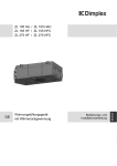
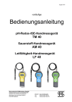
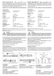
Operating instructions
Bedienungsanleitung
HygroMaxx
R/S/M
Humidity / temperature measurement instrument
for climatic control systems
Feuchte / Temperatur Messinstrument zur
Steuerung und Regelung von Klimaanlagen
www.novasina.com
-1-
© Novasina AG 2012
Printed in Switzerland
-2-
Technical data subject to modification
Technische Änderungen vorbehalten
Product description................................................................................................................... 4
Scope of delivery...................................................................................................................... 4
Safety....................................................................................................................................... 4
Installation................................................................................................................................ 4
Startup...................................................................................................................................... 5
Configuration possibilities......................................................................................................... 6
System status signals............................................................................................................... 7
Technical support..................................................................................................................... 7
Device versions........................................................................................................................ 7
Accessories.............................................................................................................................. 7
Technical data ......................................................................................................................... 8
Spare parts .............................................................................................................................. 8
Factory settings........................................................................................................................ 8
-3-
English
Table of contents
1. Product description
3. Safety
English
The Novasina HygroMaxx R, S and M transmitters
are robust precision measuring instruments for the
use in climate control systems (HVAC). They measure permanently up to 3 times per second the relative
air humidity and temperature, display the values on
a big LCD screen and give an accurate analogue
output signals for both parameters.
For measurements in rooms the HygroMaxx S is
recommended and the HygroMaxx R and M for duct
or external measurements.
Special features :
•Big LC-Display for RH & T contemporaneously
•Easy and intuitive menu (3 buttons)
•2 analogue outputs for %RH & Temp.
(U/I) freely scalable
•Adjustment capabilities
%RH & T (3 points for RH / 1 point for T)
•Average value display
(1/4 : 1 : 3 h : displayed for 5 sec.)
•Password protection for all settings
•Switch to Aout U / I and display °C or °F
•Permanent online monitoring of all functions
• The instruments leave the factory in a faultless
condition. No imappropriate manipulations or
modifications are allowed. Please consider all
notices and warning signs on the instrument and
in this operating manual.
• The HygroMaxx instrument has been developed
only for the measurement of fresh air within
the defined specifications. Use and run the instrument only for this purpose. In case of other
utilisation beyond the intended use, the supplier
declines all eventually caused damages. All risks
are assumed by the user.
• The installation work shall be only done by skilled
personnel (electrician).
• The HygroMaxx instrument may only be operated under the specified operating conditions (see
page xx).
• Anywhere faults may occur and cause damages
to material and people, additional safety precautions have to be implemented. In case of any
faults, the defined operating conditions have to
be assured (e.g. limit switch etc.).
• The HygroMaxx instrument is not adequate for
the installation in rooms with explosion hazard.
• The professional installation has to be effected
by observance of the local electrical installation
regulations as well as this operating manual.
• The HygroMaxx contains ESD-sensitive parts.
Please follow the indicated safety measures.
HygroMaxx R
HygroMaxx S
• Use only original Novasina accessories and
spare parts.
• Without any written approval by Novasina no adaptations and modifications shall be undertaken
on the HygroMaxx.
HygroMaxx M 4. Installation
General :
1.Read carefully this operating manual prior to start
with the installation of the HygroMaxx.
2. Scope of delivery
The HygroMaxx R/S/M delivery contains:
• RH/T measuring instrument including
sensor for room, duct or extended version
• Strain relief plate including screw set and
pcs distance holder
• Operating manual
• Mounting instructions
4
2.Check the performance data on the label fixed
on the instrument and make sure that they correspond with your application. Is the instrument
suitable for your application?
3.Choose the adequate mounting place according
to the application and specifications.
Check the completeness of the delivery. Incomplete deliveries will be replaced by your Novasina distributor.
-4-
4.Respect unconditionally the device specifications
and the maximum permissible concentration of
chemical burden in working environments.
English
5.Avoid to expose the instrument and the sensing
element to a corrosive environment.
Mounting :
1. Remove the bottom of the instrument. If needed
up to 4 holes can be broken through for the
mounting to a wall using screws. For mounting
to an air duct you may use the Novasina duct
flange. In this case the 4 holes shall remain
closed. Only this way the impermeability of the
housing can be assured.
2. In case of unevenness of a wall, please use
the delivered 4 distance holders for screwing the
housing to the wall.
3. Pull the cables through the housing bottom. Prior
to this operation break through the membrane.
Use a needle for punching small holes in the
membrane.
4.For a strain relief use the delivered strain relief
plate.
5. After drilling the holes in the wall and fixing the
dowels, the housing bottom can be now screwed
to the wall.
6. Screw now the cables to the core connectors.
Follow the diagram of the electrician and the
connection diagram of the instrument.
7. Check the wiring carefully before you plug the
connectors to the housing cover with integrated
electronics.
8. Lead the cover to the upper fastener and click the
cover laterally on the bottom housing part. Check
that the cover is well fixed on the bottom part.
9.After switching on the power supply, the HygroMaxx announces the functioning on the display.
Electrical
connection :
EMC notice :
1. Disturbing circuits of measurement or analysis
units have to be separated by open ground.
2. Avoid whenever possible the parallel guidance of
measurement circuits and power electro cables.
3. Shield if necessary the measurement circuits
and connect the shielding only one-sided to the
defined ground.
4. Unshielded circuits shall be always twisted by
pairs and kept as short as possible.
Recommended wiring :
Power supply : 24 VDC +/- 25%
Single cord of 0.5...0.75 mm2 (22 ... 18 AWG) with
PVC isolation or corresponding 2-fold cable.
AOUT : 0...10 VDC / 0... 20 mA
Single cord of 0.25...0.5 mm2 (24 ... 20 AWG) twisted
eventually shielded with PVC isolation or corresponding 2/3/4-fold cables.
5. Startup
Before you start the system, please check the wiring
of the power supply and the configuration of the
analogue outputs (U/I switch).Close the housing
cover of the HygroMaxx before you switch on the
power supply.
Check the fuse protection of the power supply according to the local regulations. Voltages over +35VDC
lead to a destruction of the instrument.
This device is factory calibrated and has a basic
accuracy of +/- 3.0 % RH (option +/- 1.5 % RH with
factory calibration certificate).
After switching on the power supply an automatic
startup *S TST* is performed. On the upper LCD line
the actual software version appears for 2 seconds.
Afterwards the measurement is started immediately
and the actual air humidity and temperature is displayed. In case of any faults on hard- or software
the system reports an „Error“ message with an error
code. The system disposes of an online monitoring
that reports faults immediately.
The analogue outputs are protected against shortcircuits, not against external supply though.
6. Configuration possibilities
The HygroMaxx instrument is delivered in operational status. At best the analogue outputs and the
display options have to be configured. Thereto the
HygroMaxx disposes of an intuitive menu structure,
which can be started with the „Enter“ button.
-5-
Operation :
English
ENTER : -> Menu and submenu
pushing for 2 sec. for measur. mode
[ ↑ ]* : -> Menu up, increases the
flashing digit
[ ↓ ]* : -> Menu down, decreases the
flashing digit
* Average function in measuring mode
Following menu points can be selected :
•
•
•
•
Measuring mode (standard display)
Calibration (adjustment) of RH
Calibration (adjustment) of T
Adjustment of analogue outputs
(U : 0...10V / 2...10V I : 0...20 mA / 4...20 mA)
and free scalable ranges
• Switching the unit °C or °F
• Button lock (password protection)
Each menu point can be selected with [ ↑ ], [ ↓ ]
Measuring mode :
In order to switch from a menu point to the measuring mode press the „Enter“ button for min. 2
seconds. The measuring mode is activated automatically 2 minutes after the last button activation.
The RH and T value are displayed at the contemporaneously. In case of any faults the error code is
shown instead of the temperature.
If you want to display the average RH or T value
of you may push the [ ↓ ] button in the measuring
mode. After this operation the average value of the
last 1/4 hour (1 arrow on the upper right corner of
the LCD). Pushing twice shows the average of 1h
and 3 times the one of 3 hours. After 3 seconds the
arrows disappear and the system switches back to
the measuring mode.
Calibration RH :
You can access this menu point by pressing ENTER
2 times and then [ ↓ ].
It is possible to adjust 3 RH points (Low/Medium/
High) individually. Thereby there are no range limits.
-6-
E.g. an adjustment is performed using a SAL-SC
33% humidity standard.
• Put the SAL-SC 33% RH with mounted Adapter „CH“ over the sensor probe after shaking
and visually checking it. Make sure that the
cylinder fits tightly on the sensor probe head.
• Wait at least 30 minutes (necessary for reaching a RH equilibrium inside the cylinder).
The environmental temperature shall not vary
during this time.
• Go ahead by pressing the ENTER button to
activate the adjustment mode -> „*CAL RH“
• Intercalate the humidity value using the table
label on the SAL-SC according to the actual
environment temperature (displayed on the
HygroMaxx)
• Press the ENTER button again to go to the adjustment menu -> „CAL 1“. By pressing ENTER
again, you activate the parameter setting function. The first digit flashes and you can change
the value of the digit by pressing [ ↑ ] or [ ↓ ].
(Press ENTER again for proceeding to the next
digit)
• Once you have finished all digits, press ENTER
-> the system asks if you want to save the
calibration and proposes „no SAVE“.
• Press [ ↑ ], [ ↓ ] to change to „YES“ and then
ENTER to store the data.
• The adjustment of CAL 1 is now finished. For
the next CAL point please repeat the same
procedure with the next SAL-SC standards for
CAL 2 and CAL 3.
Calibration temperature T :
The temperature adjustment can be done at 1 point
(offset of the temperature curve)
The procedure is the same as for the RH calibration.
The set point can also be cancelled with the „CAL
CLR“ function. (offsett range +/- 4.0 °C)
With the „Exit“ function the menu point can be left.
Analogue outputs :
The analogue output range can be scaled and the
range can be set (0....? / 2,4...?).
„Range L“ : low humidity value.
-> Normally = 0.0 % RH
-> Normally = 100.0 % RH
„Range H“ : High humidity value.
„Range L“ : Low temperature value
-> Normally = -20.0 °C
„Range H“ : High temperature value
-> Normally = 80.0 °C
(ANA OUT switch to 4..20mA I)
0 % RH 100 % RH
-20 °C +80°C
-> 4 mA
-> 20 mA AOUT 1
-> 4 mA
-> 20 mA AOUT 2
„ANA OUT“ : outputs can be varied depending on
the position of the „Aout“ switch :
[ ↓ ] : 0...10V / 0...20mA or 2...10V / 4...20mA
Settings display :
In this menu point can you adjust the contrast
(0...9) of the LCD display and the temperature unit
can be changed from °C (ISO unit) to US unit °F.
The commutation is done by the buttons [ ↑ ], [ ↓ ].
7. System status signals
*S TST“:
*DONE“:
*CODE?“ :
*---.-“
:
*SPACE“:
*RANGE“ :
*Power“ :
*FATAL“:
*DATA“
:
power ON reset
action effected successfully
password input necessary
sensor element fault
CAL points to close (2.0%RH)
range overstepping
operating voltage out of limits
fatal error
not enough data for moving average
Error messages :
A severe error is always shown with a error code on
the display. This code is important for a later failure
analysis. Please indicate in such cases always the
failure code.
8. Technical support
Settings & activation
Password :
In the factory setting the password is deactivated.
You can activate the 4-digit password independently.
Attention : The password activation happens
immediately after setting the code >< „0000“. Don’t
forget the password! The password reset can be only
done by a reset to factory settings and therefore all
configuration data will be cancelled!
Reset to factory settings :
All parameters, including the password code will be
set back to factory settings. This function is activated
as following :
• Switch off the power supply
• Push and keep pushed the [ ↑ ] button and
switch on again the power supply of the
HygroMaxx.
• The following text is displayed on the LCD :
„FA SET?“
• Select with the buttons [ ↑ ], [ ↓ ] „YES“
• „DONE“ is displayed and the instrument is
being restarted. Thus the instrument is reset to
the factory settings.
Novasina has a worldwide well developed distribution network. This partners offer a continuous technical support and are available at any time. Please
report any failure to your local Novasina distributor.
You can find the address on www.novasina.com.
9. Device versions
Denomination article no.
HygroMaxx S 252 3054
HygroMaxx R 252 3129
HygroMaxx M 252 3130
Measurement ranges:
T: -20 ... +80°C
%RH
: 0 ...100 %RH
10. Accessories
• Duct mounting plate with sensor clamp
• Factory calibration 3 points %RH / 1 point T
• Novasina humidity standards SAL-SC :
SAL-SC 11%RH
SAL-SC 33%RH
SAL-SC 53%RH
SAL-SC 75%RH
SAL-SC 84%RH
SAL-SC 90%RH
111 0885
111 0855
111 0857
111 0859
251 8965
111 0896
( SAL-SC 90% needs > 6h!! for a
stable humidity equilibrium )
• Adapter „CH“ to SAL-SC 110 7345
• Thermo styrobox
111 1302
-7-
English
Example :
11. Technical data
English
Type
HygroMaxx S
HygroMaxx R HygroMaxx M
Article no.
252 3054
252 3129 252 3130
Power supply
24 VDC +/- 25 % ( no galvanic isolation input-output )
Power consumption
min. 20 mA
typ. 50 mA
max. 90 mA
( current outputs )
Measuring range
-20... +80 °C
0...100.0 % RH
Operating range
0... +50°C ( electronics )
-20... +80°C
( sensor )
fresh air measuring
( max. permissible chemical burden to be respected )
Humidity/temperature sensor
digital capacitive humidity and temperature measuring system
Measurement accuracy / standard +/- 0.4 °C
( at 25°C )
+/- 1.2 °C
( 0...+50°C )
+/- 3.0 % RH ( 20...80 %RH )
+/- 5.0 % RH
( 0... 100 %RH )
Accuracy / factory calibration
+/- 0.2 °C
( at cal. point ) +/- 0.5 °C
( 0...+50°C )
(3 point %RH and 1 point Temp.) +/- 1.5 % RH ( 10...90 %RH )
+/- 4.0 % RH
( 0... 100 %RH )
Measurement hysteresis humidity
+/- 0.1°C
( 0...+50°C )
+/- 1.0 % RH
Measurement interval
330 ... 500 ms Temperature influence on measurement typical 0.06 % RH / °C
Analogue output resolution
typical 5 mV : 5 uA
Analogue output accuracy
typical 0.05% FS ( full scale )
Housing protection
IP 54
Housing material
POM
Sensor protection
IP 54 (with optional polymer membrane filter for S-type,standard for R- and M-type)
Sensor material
stainless steel / POM
Storage temperature range
5... + 55°C not condensing
EMC - CE tests
EN 61326-1 / EN 61326/A1 / EN 61010-1
Information
to Novasina
humidity standards :
12. Spare parts
Denomination
Article no.
Lower part housing 252 3135
Room sensor
Duct sensor
Remote sensor
connector set
252 3131
252 3132
252 3133
252 3134
Novasina humidity standards are
high efficient and easy to handle
humidity generators, which are
based on a chemical-physical
basis of saturated salt solutions.
The cylindric SAL-SC can be put
over the sensor element and are
generting inside its hollow space
an accurate relative humidity as
stated on its label. The SAL-SC a r e
multiple use standards and can be easily checked
visually and maintained by adding distilled water if
necessary. Please follow the following instructions
for a safe handling of the standards :
UKAS certified humidity standards :
SAL-SC 11% / UKAS
111 1044
SAL-SC 33% / UKAS
111 1037
SAL-SC 53% / UKAS
111 1040
SAL-SC 75% / UKAS
111 1035
SAL-SC 90% / UKAS
111 1032
( SAL-SC 90% needs min. 6h
for RH equilibrium )
Check visually the SAL-SC according the attached
information sheet.
• Use the Adapter „CH“ for assuring an absolutely tight
13. Factory settings
Display
temp. : -20... +80°C
humidity:
0... 100.0 % RH
AOUT 1 : temp. :
4... 20 mA / -20...+80°C
AOUT 2 : humidity : 4... 20 mA / 0...100% RH
Password
:
“0000” -> deactivated
Factory calibration : precalibrated (standard)
Optional calibration :
“CAL RH” L/M/H ( 3 points )
“CAL T”
( 1 point )
-8-
fitting of the SAL-SC onto the sensor head.
• Each SAL-SC has to be adapted to the environmental
temperature (room/duct temp.) prior to the use
• During the humidity check and adjustment the environmental temperatur may not vary
(max.
+/- 0,1°C)
• Avoid any infiltration of air during the checking and
adjustment operation (closed windows, doors)
• Shake the SAL-SC before use
• The slots of the sensor head have to be completely
inside the hollow space of the SAL-SC
• Consult the humidity table on the SAL-SC label for a
correct calibration and adjustement procedure
Inhaltsverzeichnis
Produkt Beschreibung.............................................................................................................. 10
Lieferumfang........................................................................................................................... 10
Sicherheit................................................................................................................................. 10
Installation................................................................................................................................ 10
Inbetriebnahme........................................................................................................................ 11
Konfigurationsmöglichkeiten.................................................................................................... 12
Systemmeldungen................................................................................................................... 13
Technischer Support................................................................................................................. 13
Geräteversionen....................................................................................................................... 13
Zubehör.................................................................................................................................... 13
Technische Daten .................................................................................................................... 14
Ersatzteile ................................................................................................................................ 14
Deutsch
Werkseinstellungen.................................................................................................................. 14
-9-
1. Produkt Beschreibung
3. Sicherheit
Der Novasina HygroMaxx R, S und M Transmitter
ist ein robustes Präzisions-Messinstrument für den
Einsatz in klimatechnischen Steuerungs- und Regelsystemen. Es misst permanent bis zu 3 mal pro
Sekunde die relative Luftfeuchte sowie die aktuelle
Lufttemperatur und gibt den Messwert auf eine
grosse LCD Anzeige und parallel dazu auf zwei
hochpräzisen analogen Ausgängen aus.
Für Messungen in Räumen kommt der HygroMaxx
S, für Messungen in Klimakanälen der - R, sowie
-M auch für externe Messung zum Einsatz.
Deutsch
Besondere Eigenschaften :
• Grosses LCD für gleichzeitige Anzeige von
%rH & Temperatur
• Einfache intuitive Menüführung (3 Tasten)
• 2 analoge Ausgänge für Messgrösse %rH und
Temperatur (U oder I), frei skalierbar
• Möglichkeit der Justierung von %rH und Temperatur (3 Punkte %rH / 1 Punkt Temp.)
• Mittelwert Anzeige
(1/4 : 1 : 3 h Anzeige für 3 sek.)
• Passwort-Schutz für alle Einstellungen
• Umschaltung Aout U / I und der Anzeige °C/°F
• Permanente Onlineüberwachung sämtlicher
Funktionen
• Dieses Gerät hat das Werk in sicherheitstechnisch einwandfreiem Zustand verlassen. Es dürfen keinenfalls unsachgemässe Mani-pulationen
oder Veränderungen erfolgen. Beachten sie alle
Hinweis und Warnschilder auf dem Instrument
und in der Bedienungs-anleitung.
• Der HygroMaxx ist ausschliesslich zur Messung
von Atemluft innerhalb der Spezifikationen entwickelt worden. Verwenden und
Betreiben
Sie dieses Instrument aus-schliesslich für diesen
Zweck. Eine andere oder darüber hinaus gehende Benutzung gilt als nicht bestimmungsgemäss.
Der Hersteller/Lieferant haftet nicht für mögliche
entstandene Schäden. Das Risiko trägt allein der
Anwender.
• Die Montage- und Installationsarbeiten dürfen
nur durch ausgewiesenes Fachpersonal (Elektriker oder Fachkraft mit gleichwertiger Ausbildung)
ausgeführt werden.
• Der HygroMaxx darf nur unter den spezifizierten
Betriebsbedingungen betrieben werden (siehe
Seite xx).
• Überall dort, wo auftretende Fehler oder Fehlfunktionen grosse Material- oder Personenschäden verursachen können, sind zusätzliche
Schutz- sowie externe Sicherheitsvorkehrungen
zu treffen, so dass im Fehlerfall ein definierter
Betriebszustand gewährleistet wird (z.B. Grenzwertschalter usw.).
• Der HygroMaxx ist nicht für den Einsatz in explosionsgefährdeten Räumen geeignet.
HygroMaxx R
HygroMaxx S
• Die fachgerechte Installation soll durch
Beachtung der lokalen Elektro Installationsvorschriften sowie dieser Bedienungsanleitung erfolgen.
• Der HygroMaxx enthält ESD-empfindliche Bauteile. Beachten Sie bitte die entsprechenden
Sicherheitsmassnahmen.
HygroMaxx M • Verwenden Sie ausschliesslich Original-Zubehör
und Ersatzteile von Novasina.
• Ohne schriftliche Genehmigung seitens Novasina dürfen am HygroMaxx keine An- und
Umbauten vorgenommen werden.
2. Lieferumfang
Der HygroMaxx R/S/M enthält:
• RH/T Messinstrument inklusive
Sensor in Raum-, Kanal- bzw. ext. Version
• Zugentlastungsplatte inklusive
Schrauben-Set und 4 Stk. Distanzhalter
• Bedienungsanleitung
• Montageanleitung
4. Installation
Überprüfen Sie die Vollständigkeit des Lieferumfangs.
Unvollständige Lieferungen können von Ihrer Novasina
Vertretung umgehend ergänzt werden.
- 10 -
Allgemeines :
1.Vor der Installation des HygroMaxx Instruments
ist die Bedienungsanleitung sorgfältig zu lesen.
2.Überprüfen Sie die Leistungsdaten auf dem
Leistungsschild des Instruments und ob diese
für Ihre Anwendung geeignet ist.
Montage :
1. Entfernen Sie zuerst den Boden des Instruments.
Bei Bedarf können maximal 4 Durch-brüche für
die Montage an einer Wand oder am Lüftungskanal ausgebrochen werden. Bei der Montage
an einem Lüftungskanal mittels Novasina Kanalflansch sollten die Durchbrüche geschlossen
bleiben. Nur so kann die Gehäusedichtigkeit
gewährleistet bleiben.
2. Bei Unebenheit der Montagewand können
zusätzlich die 4 Distanzhalter montiert werden.
3. Führen Sie die entsprechenden Kabel über die
im Boden vorhandene Membrane ein, indem Sie
kleine Löcher mit einer spitzigen Anreisnadel in
die Membrane stechen und danach die Kabel
(nur Einfach -Isolation) durch die Löcher stossen.
4.Für eine Kabel-Zugentlastung bitte die Zugentlastungsplatte verwenden.
5. Nach dem Setzen der Dübel bzw. bohren der
entsprechenden Löcher in der Wand kann der
Boden angeschraubt werden.
6. Nun können die Kabel auf die Stecker
mit
Aderendhülsen geschraubt werden.
Dazu beachten Sie bitte die entsprechenden
Elektroschemas des Planers bzw. des Instruments.
7. Überprüfen Sie die Verkabelung genau, bevor
die Stecker auf den Deckel mit der integrierten
Elektronik angeschlossen werden.
8. Führen Sie den Deckel in die oberen Halterungen
ein und klicken Sie ihn seitlich auf den Boden ein.
Überprüfen Sie den korrekten Sitz.
9.Nach dem Einschalten der Speisespannung
meldet sich der HygroMaxx über die Anzeige.
Elektrische
Anschlüsse :
EMV Hinweise :
1. Störungsaussendende Leitungen von Messoder Auswerteinheiten sind räumlich zu
trennen.
2. Vermeiden Sie, wo immer möglich die parallel
Führung von Messleitungen und LeistungsElektrokabeln.
3. Schirmen Sie, wenn nötig, die Messleitungen
ab und verbinden Sie den Schirm nur einseitig
mit einem definierten Massepotential.
4. Ungeschirmte Leitungen immer paarweise
verdrillen und möglichst kurz halten.
Empfohlene Verkabelung :
Speisung : 24 VDC +/- 25%
Einzel-Litzen von 0.5...0.75 mm2 (22 ... 18 AWG)
mit PVC Isolation oder entsprechende 2-fach
Litzenkabel.
AOUT : 0...10 VDC / 0... 20 mA
Einzel-Litzen von 0.25...0.5 mm2 (24 ... 20 AWG)
verdrillt evtl. geschirmt mit PVC Isolation oder
entsprechende 2/3/4-fach Litzenkabel.
5. Inbetriebnahme
Überprüfen Sie bitte vor der Inbetriebnahme noch
einmal die richtige Speisungsverdrahtung und die
Konfiguration der analogen Ausgänge (U/I Schalter).
Schliessen Sie den Deckel des HygroMaxx bevor
Sie die Stromversorgung einschalten.
Überprüfen Sie die Absicherung der Speisung
gemäss den geltenden lokalen Vorschriften. Spannungen über +35VDC führen zur Zerstörung des
Messinstruments!
Der HygroMaxx ist werkskalibriert auf eine Grundgenauigkeit von +/- 3.0 % rH. (Option +/- 1.5 % rH
mit Werkszertifikat).
Nach dem Einschalten der Speisespannung erfolgt
ein automatischer Startup *S TST* des Instruments.
Auf der oberen Zeile der Anzeige wird für 2 Sekunden die aktuelle Software Version angezeigt.
Danach wird sofort die Messung gestartet und
die aktuelle relative Luftfeuchte und Temperatur
angezeigt. Bei allfälligen Fehlern der Hard- oder
Software meldet sich das System mit „Error“ und
einem Fehler-Code. Das Gerät verfügt über eine
Online Überwachung, welche Fehler sofort meldet.
Die analogen Ausgänge sind gegen Kurzschluss,
jedoch nicht gegen Fremd-Einspeisung geschützt.
- 11 -
Deutsch
3.Wählen Sie den geeigneten Montagestandort
je nach Applikation und Spezifikation (evtl. in
Zusammenarbeit mit dem Planer) aus.
4.Beachten Sie unbedingt, dass die Geräte-spezifikationen und die MAK-Werte (maximale Arbeits
Konzentration für chemische Belastungen für
Handwerkberufe) übereinstimmen.
5.Vermeiden Sie, dass das Instrument und der
Sensor einer ätzenden Umgebungsluft ausgesetzt wird.
6. Konfigurationsmöglichkeiten
Der HygroMaxx wird funktionsbereit ausgeliefert.
Allenfalls müssen die analogen Ausgänge sowie
die Anzeigeoptionen für die Anwendung konfiguriert
werden. Dazu verfügt das Instrument über eine
intuitive Menüstruktur, die über die Taste „Enter“
gestartet wird.
Bedienung :
ENTER : -> Menü und Untermenüs
2 Sek. drücken für Wechsel
[ ↑ ]* : -> Menü nach oben, erhöht die
blinkende Ziffer
[ ↓ ]* : -> Menü nach unten, verringert die
blinkende Ziffer
* Average Funktion im Messmodus
Folgende Menü Punkte können aufgerufen werden:
Deutsch
Messmodus (Standard & Mittelwert Anz.)
Kalibration (Justierung) der rel. Feuchte
Kalibration (Justierung) der Temperatur
Justierung der analogen Ausgänge
(U: 0,2...10V - I: 0,4...20 mA)
und freie Skalierung der Bereiche
• Umschaltung Einheit °C oder °F
• Tastensperrcode (Passwortschutz)
•
•
•
•
Jeder Menüpunkt kann über [ ↑ ], [ ↓ ] angewählt
werden.
Messmodus :
Um von einem Menüpunkt direkt in den Messmodus
zu kommen drücken Sie für mind. 2 Sek. die „Enter“
Taste. Der Messmodus wird 2 Min. nach dem letzten Tastendruck automatisch aktiviert. Es werden
gleichzeitig die relative Luftfeuchte und Temperatur
(in °C od. °F) angezeigt. Bei Fehlern wird anstelle
der Temperatur ein Fehlercode angezeigt.
Soll der arithmetische Mittelwert der rel. Luftfeuchte
rsp. der Temperatur angezeigt werden, so kann im
Messmodus die Taste [ ↓ ] gedrückt werden. Es
erscheint dann der Mittelwert der letzten 1/4 h (1Pfeil
rechts oben auf der LCD). Zweimaliges drücken
zeigt den Mittelwert von 1h und 3-maliges drücken
den Mittelwert der letzten 3h an. Nach rund 3 sek.
erlöschen alle Pfeile und das System geht in den
aktuellen Messmodus über.
- 12 -
Kalibration RH :
Sie erreichen diesen Menüpunkt indem Sie ENTER
-> „*CAL RH“ -> ENTER -> „CAL 1“ -> ENTER
drücken.
Es besteht die Möglichkeit 3 Feuchte Messpunkte
(1: Low / 2: Medium / 3 : High) einzeln zu justieren.
Dabei bestehen keine Einschränkungen.
Als Bsp. wird im folgenden die Justierung mittels
eines SAL-SC 33% aufgezeigt.
• Stülpen Sie das SAL-SC 33% rH zusammen
mit dem Adapter „CH“ über den Sensor nach
dem Sie das SAL-SC entsprechend visuell
überprüft und geschüttelt haben. Vergewissern
Sie sich, dass der Zylinder dicht über dem
Sensor liegt.
• Warten Sie mind. 30 min. (nötig für Ausgleich
der Feuchte im Innern des Zylinders). Dabei
darf die Umgebungstemperatur möglichst nicht
ändern (SAL-SC 90%RH >3h warten!).
• Gehen Sie durch drücken der ENTER Taste
um in den Änderungsmode zu gelangen
• Lesen Sie auf der Tabelle des SAL-SC den erzeugten Feuchtewert bei der entsprechenden
Raumtemperatur ab (auf HygroMaxx). Ev. ist
es nötig den Wert entsprechend zu interpolieren.
• Stellen Sie nun mit den Tasten [ ↑ ], [ ↓ ] den
gewünschten Feuchtewert ein (ENTER für die
nächste Ziffer!)
• Nach der letzten Ziffer erscheint die Anzeige
„no SAVE?“ Durch drücken der Tasten [ ↑ ],
oder [ ↓ ] wechseln sie auf „YES SAVE?“ und
schliessen Sie die Funktion mit der ENTER
Taste ab (kurz erscheint „*DONE*“ auf der
Anzeige).
• Der Justierpunkt „CAL 1“ ist nun beendet.
Kalibration Temperatur :
Die Justierung der Temperaturmessung erfolgt nur
in 1 Punkt (Offsetverschiebung der Temp. Kurve)
Die Vorgehensweise ist gleich wie bei der Kalibration
RH. Auch hier kann ein eingegebener Punkt mittels
der weiteren Menü-Funktion „CAL CLR“ einfach
gelöscht werden. (Bereich +/- 4.0 °C)
Mit „Exit“ verlassen Sie diesen Menüpunkt wieder.
Analoge Ausgänge :
In dieser Funktion kann die Skalierung der analogen
Ausgänge sowie der Bereich 0....10V/0...20mA oder
2...10V/4...20mA eingestellt werden.
„Range L“ : Unteren % RH Feuchtewert
-> Normalerweise = 0.0 % RH
Beispiel : (ANA OUT : 4 - 20 / Schalter I)
0.0 % RH -> 4 mA
100.0 % RH -> 20 mA AOUT 1
- 20.0 °C -> 4 mA
+80.0 °C -> 20 mA AOUT 2
„ANA OUT“ : Ausgänge können abhängig von der
Schalterstellung „Aout“ verändert werden:
[↓] U : 0 - 10V <-> 2 - 10V
I : 0 - 20mA <-> 4 - 20mA
Einstellung Display :
In diesem Menüpunkt kann einerseits der Kontrast
der LCD Anzeige, sowie die Einheit der Temperatur
von °C (ISO Einheit) auf das US Format °F umgeschaltet werden. Die Umschaltung erfolgt durch
drücken der Tasten [ ↑ ], [ ↓ ].
Einstellung & Aktivierung
Passwort :
Werkseitig ist das Passwort deaktiviert. Sie können
ein Passwort (4 Ziffern) selbständig aktivieren.
Achtung : Die Aktivierung des Passwortes erfolgt
durch setzen des Codes >< „0000“ und aktivieren
im Menü „Lock“ spätestens jedoch nach 2 Min
(ohne Bedienung). Notieren Sie Ihr Passwort.
Das Rücksetzen des Passworts kann nur über die
Werksrücksetzfunktion erfolgen. Damit werden auch
alle Konfigruationsdaten gelöscht und die Werkseinstellungen übernommen.
Menü : *KEYLO -> ENTER -> CODE -> ENTER
-> Setzen des Passwortes -> [ ↑ ] LOCK
& ENTER -> Passwort aktiviert *DONE*
Rücksetzung auf Werkseinstellungen :
Alle Parameter inkl. Passwort Code werden auf die
Werkseinstellung zurückgesetzt. Diese Funktion
wird folgendermassen aktivitert :
• Schalten Sie die Speisespannung aus.
• Drücken und halten Sie bei ausgeschalteter
Speisung die [ ↑ ] Taste und schalten Sie die
Speisung des HygroMaxx wieder ein.
• Auf der Anzeige erscheint folgender Text :
„FA SET?“
• Selektieren Sie mit den Tasten [ ↑ ], [ ↓ ]
„YES“
• „DONE“ wird angezeigt und das Instrument
neu gestartet. Das Gerät ist somit auf die
Werkseinstellungen zurück gesetzt.
7. Systemmeldungen
*S TST“ :
*DONE“ :
*CODE?“:
*---.-“
:
*SPACE“:
*RANGE“:
*Power“ :
*FATAL“ :
*DATA“ :
Power ON reset
Aktion erfolgreich ausgeführt
Eingabe Passwort nötig
Sensor Element defekt
CAL Punkte liegen zu nahe (2.0%RH)
Bereichsüberschreitung
Betr.Spannung ausserhalb der Limiten
Schwerwiegender Fehler
Zu wenig Daten für Moving Average
Fehler-Meldungen :
Ein schwerwiegender Fehler wird zusammen mit
einem Fehlercode angezeigt. Dieser ist für die
Fehleranalyse wichtig. Bitte übermitteln Sie uns in
solchen Fällen immer auch den Fehlercode.
8. Technischer Support
Novasina hat weltweit ein gut ausgebautes Vertreternetz, welches mit versierten Technikern einen
jederzeit präsenten Service anbietet. Melden Sie allfällige Störungen Ihrem lokalen Novasina-Vertreter.
www.novasina.com.
9. Geräteversionen
Bezeichnung
Artikel Nr.
HygroMaxx S
HygroMaxx R
HygroMaxx M
252 3054
252 3129
252 3130
Messbereich T :
%RH
Betriebsbereiche :
Elektronik / Gehäuse
Sensor (ext. / Kanal)
:
:
-20 ... +80°C
: 0 ... 100 %RH
0... +50°C
-20... +80°C
10. Zubehör
• Kanalmontageplatte mit Sensorklemmung
• Werkskalibrierung 3 Pkte %RH / 1 Pkt Temp.
• Novasina Feuchte Standards SAL-SC :
SAL-SC 11%RH
SAL-SC 33%RH
SAL-SC 53%RH
SAL-SC 75%RH
SAL-SC 84%RH
SAL-SC 90%RH 111 0885
111 0855
111 0857
111 0859
251 8965
111 0896
( SAL-SC 90% braucht eine Wartezeit von
-> zu 6h für das Feuchtegleichgewicht)
• Adapter „CH“ zu SAL-SC 110 7345
• Thermo Styrobox (Isolation) 111 1302
- 13 -
Deutsch
„Range H“ : Oberen % RH Feuchtewert
-> Normalerweise = 100.0 % RH
„Range L“ : Unteren Temperaturwert
-> Normalerweise = -20.0 °C
„Range H“ : Oberen Temperaturwert
->Normalerweise = +80.0 °C
11. Technische Daten
Typ
Artikel-Nr.
Versorgungsspannung
Stromverbrauch
Messbereich
Einsatzbereich
Feuchte/Temperatur Sensor
Messgenauigkeit Standard Messgenauigkeit Option
( mit 3 Pkt RH / 1 Pkt T Werksjustierung )
Messhysterese Temperatur / Feuchte
Messintervall
Temperatureinfluss auf Messung
Auflösung der analogen Ausgänge
Genauigkeit der analogen Ausgänge
Schutzklasse Gehäuse
Material Gehäuse
Schutzklasse Sensor
Material Sensor
Lager-Temperaturbereich
EMV - CE Prüfungen
HygroMaxx S
HygroMaxx R HygroMaxx M
252 3054
252 3129
252 3130
24 VDC +/-25% ( keine galv.Ioslation von Ein & Ausgang )
min. 20 mA
typisch 50 mA
max. 80 mA
( Stromausgänge )
-20... +80°C
0... 100.0 % RH
0... +50°C
( Elektronik ) -20... +80°C
( Sensor )
Atemluft Messung
( MAK Werte eingehalten )
Digitales kapazitives Feuchte- / Temperatur-Messsystem
+/- 0.4 °C
( bei 25°C )
+/- 1.2 °C
( 0...+50°C )
+/- 3.0 % RH ( 20...80 % RH )
+/- 5.0 % RH
( 0... 100 % RH )
+/- 0.2 °C
( bei 25°C ) +/- 1.0 °C
( 0...+50°C )
+/- 1.5 % RH ( 10...90 % RH )
+/- 4.0 % RH ( 0... 100 % RH )
+/- 0.1°C
+/- 1.0 % RH
330 ... 500 ms
typisch 0.06 % RH / °C
typisch 5 mV : 5 uA
typisch 0.05% FS ( vom gesamten Messbereich )
IP 54
POM
IP 54 ( mit Polymer Membranfilter für S-Typ als Option, standard for R- und M-Typ )
Rostfreier Edelstahl / POM
5... + 55°C nicht kondensierend !
EN 61326-1 / EN 61326/A1 / EN 61010-1
Informationen zu den
Novasina Feuchte Standards:
12. Ersatzteile
Deutsch
Bezeichnung
Novasina Feuchte Standards sind
äusserst effiziente, einfach zu handhabende „Feuchte Generatoren“ die auf
chemisch- physikalischer Basis von
gesättigten Salzlösungen basieren.
Die zylinderförmigen SAL-SC können
über den Sensor gesteckt werden und
erzeugen im Inneren eine präzise relative Luftfeuchte. Diese Werte sind auf
der am Zylider aufgeklebten Etikette
ersichtlich. Die SAL-SC mehrmals verwendet werden
und lassen sich einfach und schnell visuell überprüfen
und warten (nachfüllen von VE- Wasser). Bitte beachten
Sie folgende Punkte für eine sichere und sachgemässe
Anwendung :
Artikel Nr.
Gehäuseboden
252 3135
Raumsensor 252 3131
Kanalsensor 252 3132
Ext. Sensor 3m
252 3133
Steckerset 252 3134
UKAS zertifizierte Feuchte-Standards :
SAL-SC 11% / UKAS
111 1044
SAL-SC 33% / UKAS
111 1037
SAL-SC 53% / UKAS
111 1040
SAL-SC 75% / UKAS
111 1035
SAL-SC 90% / UKAS
111 1032
Überprüfen sie visuell das SAL-SC gemäss den FeuchteStandards beigelegtem Informationsblatt.
( SAL-SC 90% braucht eine Wartezeit
bis zu 6h für das Feuchtegleichgewicht !! )
13. Werkseinstellungen
Anzeige : Temp. : -20... +80°C
Feuchte :
0... 100.0% RH
AOUT 1 : Temp. :
4... 20 mA / -20...+80°C
AOUT 2 : Feuchte:
4... 20 mA / 0...100% RH
Passwort
:
“0000” -> deaktiviert
Werksjustierung : vorkalibriert (standard)
Opt. Kalibrierung : “CAL RH” L/M/H
( 3 Pkt )
“CAL T”
( 1 Pkt )
- 14 -
• Verwenden Sie den Adapter „CH“ für einen dichten
und festen Sitz des SAL-SC auf dem Sensor.
• Jedes SAL-SC muss vor der Verwendung auf die
entsprechende Umgebungstemperatur gebracht
werden (z.B. Lagerung in Raum)
• Während der Überprüfung und Justierung darf die
Umgebungstemperatur nicht variieren. (+/- 0,1°C)
• Vermeiden Sie Zugluft am System während der
Überprüfung
• Schütteln Sie das SAL-SC kräftig unmittelbar vor
dem Gebrauch.
• Die Schlitze des Sensors müssen unbedingt vollständig von SAL-SC befinden.
• Konsultieren Sie unbedingt die auf dem SAL-SC
aufgeklebte Tabelle für eine korrekte Justierung.
- 15 -
Deutsch
We would like to thank you for your confidence and hope you will enjoy and obtain successful measurements with the HygroMaxx instrument and its manifold
options.
In case of any further questions, Novasina and its agencies will be happy to
advise you at any time.
Manufacturer :
Novasina AG
Neuheimstrasse 12
CH - 8853 Lachen SZ
Switzerland
Tel. : +41/ (0)55-642-67-67
Fax.: +41/ (0)55-642-67-70
Internet : www.novasina.com
E- Mail : [email protected]
www.novasina.com
- 16 -
Your Novasina Team
252 3179 / 300’000’251.02
Technical changes possible
Technische Änderungen vorbehalten
Modifications techniques sous réserve