1
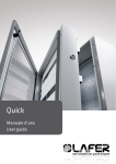
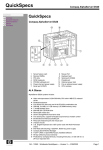
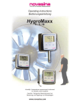
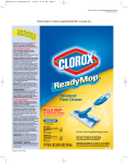
COMMERCIAL MICROWAVE OVEN
EM-S1000
EM-E1000
SERVICE MANUAL
CAUTION
Before servicing the oven, read the “Safety Precautions” section on page 2 of this manual.
SPECIFICATIONS
CONTENTS
MODEL EM-S1000
Power Source:
Max. Output Power:
Cavity Size:
Overrall Dimensions:
Net Weight:
230V AC, 50Hz
1000 watts
0.8 cu-ft
520(W)x412(D)x296(H)mm
17 kgs
Model EM-E1000
Power Source:
Max. Output Power:
Cavity Size:
Overall Dimensions:
Net Weight:
230V AC, 50Hz
1000 watts
1.0 cu-ft
520(W) x 412(D)x296(H)mm
17 kgs
Safety Precautions.......................................................................Cover
Installation Instructions ........................................................................2
General Information.............................................................................2
Microwave Radiation Test ...................................................................2
Safety Precautions for Disassembly and Repair.................................3
Description & Function of Components...............................................3
Electrical Operation .............................................................................4
Door & Interlock Adjustments ..............................................................4
Component Test Procedures ...............................................................5
Disassembly & Replacement of Parts.................................................6
Wiring Diagram ...................................................................................9
Schematic Diagram ............................................................................10
Exploded View ..................................................................................11-16
Exploded View Parts List...................................................................17-18
Product Code No.
NOTICE
EM-S1000 ECO 1-437-602-04
EM-S1000 EUK 1-437-602-05
EM-E1000
This service information is intended for use by a service technician who is familiar with proper and safe procedures to be followed
when repairing any electrical or gas appliance and who is equipped with proper tools and testing devices. Repairs covered in this
publication and made by uninformed persons can result in hazards developing due to improper assembly or adjustment. While making such repairs, persons not having the proper background may subject themselves to the risk of injury or electrical shock which
can be serious or even fatal.
A. If the oven is operative prior to servicing, a microwave emission check should be performed prior to servicing the oven.
B. Inform the manufacturer, importer, or assembler of any certified oven unit found to have a microwave emission level in excess
of 5 mW/cm2. Repair any unit found to have excessive emission levels at no cost to the owner (see 21 CFR 1004.2) and attempt
to ascertain the cause of the excessive leakage. The owner of the unit should be instructed not to use the unit until the oven
has been brought into compliance.
C. If the oven operates with the door open: 1) tell the user not to operate the oven and 2) contact the manufacturer and/or importer
and CDRH immediately.
D. Remember to connect the monitor switch after replacement and to check interlock/monitor continuity.
IMPORTANT NOTE TO THE CONSUMER
The manufacturer will not be responsible for injury or property damage arising from service performed by anyone other than authorized Service Centers. If you perform service on your own products, you must assume responsibility for personal injury or property
damage which may result.
02-03
REFERENCE NO. SM-2400012
PRECAUTIONS TO BE OBSERVED BEFORE AND
DURING SERVICING TO AVOID POSSIBLE EXPOSURE TO EXCESSIVE MICROWAVE ENERGY
(a) Do not operate or allow the oven to be
operated with the door open.
(b) Make the following safety checks on all
ovens to be serviced before activating
the magnetron or other microwave
source and make repairs as necessary:
(1 ) Interlock operation, (2) proper door
closing, (3) seal and sealing surfaces
(arcing, wear, and other damage), (4)
damage to or loosening of hinges and
INSTALLATION INSTRUCTIONS
IMPORTANT: BEFORE
THE
UNIT
IS
INSTALLED, INSPECT THE
OVEN AND DETERMINE IF ANY
OF THE FOLLOWING DAMAGE
CONDITIONS EXIST.
1. The door does not close firmly against the
door support because the door is warped or
the hinge is damaged.
2. Either the door seals or the trim is damaged.
3. If there is any visible damage to the oven.
If any of the above conditions exist, DO NOT
OPERATE THE OVEN. Call your local authorized service representative.
If none of the above conditions exist, proceed
with properly installing the oven.
A minimum clearance of 3” on both sides and 1”
on top and rear must be observed. This will
allow proper internal ventilation of the unit. Also,
do not remove the legs because of the possibility of restricting the ventilation.
WARNING
ELECTRICAL GROUNDING INSTRUCTIONS
latches, (5) evidence of dropping or
abuse.
(c) Before turning on microwave power for
any service test or inspection within the
microwave generating compartments,
check the magnetron, waveguide or
transmission line, and cavity for proper
alignment, integrity, and connections.
d) Any defective or misadjusted components in the interlock, monitor, door seal,
and microwave generation and transmission systems shall be repaired, replaced,
or adjusted by procedures described in
this manual before the oven is released
to the owner.
(e) A microwave leakage check to verify
compliance with the Federal performance
standard should be performed on each
oven prior to release to the owner.
Check all code rules and regulations for connecting the appliance to be certain the installation conforms with all local, municipal and state codes as
well as local utility regulations.
2. The door seals or door trim are damaged.
3. If there is any visible damage to the oven.
Where a two-prong wall receptacle is encountered, it is the personal responsibility of the user
to contact a qualified electrician and have it
replaced with a properly grounded three-prong
wall receptacle in accordance with the National
Electrical Codes.
DO NOT use a two-prong adapter, since proper
grounding is not assured even if the ground wire
or metal tab is connected to the outlet box.
The use of an extension cord is not recommended. However,if it is necessary to use an
extension cord, it must be a type s, with 3 number 14 wires and have a 3 prong grounded plug.
The extension cord should not drape over a
countertop where it can be pulled on or tripped
over accidentally.
Under no circumstances should the rounded
ground prong be removed from the plug.
Failure to comply with the above could result in
a serious shock hazard .
GENERAL INFORMATION
This appliance is equipped with a three-prong
grounding plug for your protection against shock
hazard and must be plugged directly into a
properly grounded receptacle.
Use a properly polarized and grounded three
hole receptacle as is required by NATIONAL
ELECTRICAL CODES on all new construction.
NOTE: APPLIANCE MUST BE GROUNDED
3-PRONG GROUNDING PLUG
WALL RECEPTACLE
POWER SUPPLY CORD
WITH 3-PRONG
GROUNDING PLUG
For the safety of the user, it is required that all
major appliances requiring electricity for operation be electrically grounded in accordance with
the National Electrical Code ANSI C1-1981.
IMPORTANT:
BEFORE PROCEEDING,
THE FOLLOWING INFORMATION MUST BE
CAREFULLY READ TO AVOID POSSIBLE
EXPOSURE TO MICROWAVE RADIATION.
Before servicing the oven, unplug the oven,
remove the cabinet and take a continuity reading of the interlock switches to assure they are
operating properly.
Refer to the Component Test Section in this
service manual.
Also, it is very important to insure that the door
seals are not damaged. If a microwave leakage
instrument is available, check the oven for any
possible microwave leakage.
Do not operate the oven if the following conditions exist.
1. The door does not close firmly against the
door support because of the door being
warped or the hinge is damaged.
2
Do not operate the oven if the front frame of the
oven is dirty or if the interlocks are loose.
Microwave leakage may be present if these
conditions exist.
Do not operate the oven if:
1. any door gaskets or trim surrounding the oven
door or control panel are missing.
2. the waveguide and oven cavity are not intact.
3. the door does not close properly.
Avoid operating the oven if known components
in the interlock, oven door or microwave generting
transmission assembly are defective. They must
be replaced.
After the above precautions have been taken,
proceed with normal repair procedures.
Remember that high voltage is present, so
use caution to avoid electrical shock.
MICROWAVE RADIATION TEST
NOTE: A MICROWAVE LEAKAGE CHECK
SHOULD BE PERFORMED AFTER ANY
REPAIRS OR ADJUSTMENTS HAVE BEEN
MADE ON THE DOOR, FRONT FRAME
AND/OR INTERLOCK SWITCHES,
IMPORTANT: IF THE READING IS OVER 2
mW/cm2, REFER TO THE DOOR AND INTERLOCK ADJUSTMENTS SECTION IN THIS MANUAL. THE DOOR IS DESIGNED FOR LEAKAGE
2
OF LESS THAN 1 mW/cm , ADJUSTMENTS
SHOULD BE MADE TO BRING ALL READINGS
2
TO BELOW 1 mW/cm .
The microwave leakage measurement equipment manufacturers presently acceptable are
NARDA, SIMPSON and HOLADAY. More information on these units can be obtained from the
respective equipment manufacturers.
TO PERFORM MICROWAVE LEAKAGE CHECK:
1. Fill 275 milliliters or 9 ounces of tap water
in a 2 cup measuring cup.
2. Place the container in the center of the
oven cavity on the glass tray.
3. Set power control for microwave “Cook”
(high) or 100% operation. Set timer for 3
minutes.
4. Close the door securely and start the oven.
5. Perform the proper adjustment and operations check with the microwave leakage
meter (refer to the operation instructions
with the meter). Check the oven by moving
the probe, starting at the top right-hand
side of the door, clockwise no faster than
one inch per second, back to the starting
position. Also, a check over the entire visual screen must be made.
no heating power.
An open filament lead or “dead” filament transformer will give the same indication as an open
filament in the magnetron. This possibility
should be eliminated before the magnetron is
considered open.
(4)
INTERNAL PLATE CATHODE SHORT
A shorted magnetron will give the same indications as the loss of vacuum.
(5)
MODING
Moding occurs when the magnetron momentarily operates at a different frequency and a higher voltage than designed. Moding results in low
heating power. Moding is usually caused by the
cathode losing emission characteristics.
LOW POWER
Low emission will result in low cooking power.
Food will require a longer than normal cooking
time. It can be detected by a lower than normal
water temperature rise.
LOW EMISSION
Caused by “wearout” of the emission characteristics of the directly heated cathode. The
tube current does not get high enough to cause
the tube to oscillate with normal line voltage.
Everything will appear normal, but the tube will
not heat.
SAFETY PRECAUTIONS FOR DISASSEMBLY AND REPAIR
Probe Speed: One inch per second (max.)
IMPORTANT:
MICROWAVE
LEAKAGE
CHECK MUST BE PERFORMED ON THE
REAR VENTS AND SIDE VENTS.
NOTE: THE METER PROBE MUST BE
HELD APPROXIMATELY TWO INCHES
FROM THE POINT OF MEASUREMENT. THIS
IS ACCOMPLISHED BY THE USE OF A TWOINCH (5 cm) PLASTIC SPACER THAT IS SUPPLIED WITH THE METER. IT IS NORMALLY
ATTACHED TO THE PROBE.
6. The maximum allowable microwave leakage level is 5mW/cm2 by government standard.
IMPORTANT: IF THE READING IS OVER 2
mW/cm2, REFER TO THE DOOR AND INTERLOCK ADJUSTMENTS SECTION IN THIS MANUAL. THE DOOR IS DESIGNED FOR LEAKAGE
2
OF LESS THAN 1 mW/cm , ADJUSTMENTS
SHOULD BE MADE TO BRING ALL READINGS
2
TO BELOW 1 mW/cm .
-Cautions to be observed when troubleshooting.
Unlike many other appliances, the microwave
oven is a high-voltage, high-current piece of
equipment. It is completely safe during normal
operation. However, carelessness in servicing
the oven can result in an electric shock or possible danger from a short circuit.
You are asked to observe the following precautions carefully.
(1) Always remove the power plug from the outlet before servicing.
(2) Use an insulated screwdriver and wear rubber gloves when servicing the high voltage side.
(3) Discharge the high voltage capacitor before
touching any oven components or wiring.
1. Check the grounding.
Do not operate on a 2-wire extension
cord. The microwave oven is designed to
be used when grounded. It is imperative,
therefore, to make sure it is grounded
properly before beginning repair work.
MAGNETRON FAILURE MODES
LOSS OF VACUUM
This is a case where the tube has had the vacuum envelope destroyed and air has entered
the tube. This will cause internal arcing. With
continued use, the transformer will eventually
fail and the circuit fuse will blow.
OPERATION FAULTS
OPEN FILAMENTS
A magnetron with an open filament will produce
(6)
high voltage capacitor. When replacing or
checking parts, create a short between
oven chassis and the negative high terminal of the high voltage capacitor, by using
a properly insulated screwdriver to discharge it.
When the 10 Amp. fuse is blown out due
to the operation of the monitor switch,
replace primary and secondary interlock
switches, monitor switch and relay 2.
After repair or replacement of parts, make
sure that the screws are properly tightened, and all electrical connections are
tightened.
Do not operate without cabinet.
DESCRIPTION & FUNCTION OF COMPONENTS
FAN MOTOR
The fan motor drives a blower fan which draws
cool air through the back of the oven. This cool
air is directed through the air ducts surrounding
the magnetron tube to cool the magnetron.
Some of the air is then exhausted directly
through the bottom vents.
However, a portion of this air is channeled
through the cavity to remove the steam and
vapors given off from heating food.
OVEN LIGHT
The oven light illuminates the interior of the
cavity so the food can be visually examined
through the door.
POWER TRANSFORMER
The purpose of the power transformer is to provide the filament voltage for heating the magnetron filaments as well as to produce the high
voltage needed for magnetron tube operation.
During a cook cycle, the ‚230 Volts AC applied
to the primary winding is converted to approximately 3.22 Volts AC on the filament winding.
The same 230 Volts AC primary input is converted to approximately 2070 Volts AC on the
high voltage secondary winding of the power
transformer.
CAUTIONS: AFTER REMOVING THE CABINET, DISCHARGE THE CAPACITOR BY
PLACING AN INSULATED SCREWDRIVER
ACROSS THE TERMINALS.
PRIMARY
SWITCH
(UPPER)
INTERLOCK
The primary protective switch (interlock) is activated by the latch when the door is closed. The
switch, in the open position when the door is
open, interrupts the current to the magnetron.
Closing the door will close the interlock switch
and normal operations can be continued.
SECONDARY (LOWER) INTERLOCK
SWITCH
Short
2.
Warning about the electric charge in
the high voltage capacitor.
For about 60 seconds after the operation
stops, an electric charge remains in the
3
The secondary protective interlock switch is
located behind the front control panel and is activated when the door is closed. When the door is
open, this switch will interrupt the circuit.
MONITOR
SWITCH
(MIDDLE)
INTERLOCK
This interlock switch disables the control panel
if the door is open or the catch is out of adjustment or the primary interlock switch fails.
If for some reason the primary switch and secondary switch stick in the closed position and
the door were to be opened, the circuit would
be shorted through the normally closed safety
switch. This would blow the fuse.
If there appears to be an interlock switch problem, but the fuse is not blowing, refer to the
Component Test Procedure Section in this
service manual.
NOTE:IF THE INTERLOCK SWITCHES ARE
REPLACED, THE CATCH MUST BE ADJUSTED. SEE DOOR AND INTERLOCK ADJUSTMENTS SECTION FOR PROPER ADJUSTMENT PROCEDURE. DEFECTIVE SWITCHES
SHOULD BE DESTROYED TO PREVENT
POSSIBLE FUTURE USE.
IMPORTANT: IF AT ANY TIME THE OVEN
FUSE BLOWS DUE TO AN OVEN FAULT, OR
THE CIRCUIT BREAKER TRIPS AFTER BEING
RESET ONE
TIME WITH THE HOUSE
CIRCUIT UNLOADED EXCEPT FOR THE
OVEN, THE INTERLOCK SWITCHES MUST
BE REPLACED AS A GROUP. THIS IS
BECAUSE THE SHORT CIRCUIT CURRENTS
WILL HAVE DAMAGED THESE IMPORTANT
SWITCHES.
MAGNETRON THERMAL PROTECTOR
The magnetron thermal protector located on
the magnetron is designed to prevent an overheated condition in the tube due to fan failure,
obstructed air ducts, etc.
Under normal operating conditions, the thermal
protector remains closed. However, If abnormally high temperatures within the magnetron
approach a critical level, the thermal protector
will interrupt the circuit to the magnetron. When
the magnetron has cooled to a safe operating
temperature, the thermal protector closes and a
cook (or defrost) cycle can be resumed.
HALF-WAVE VOLTAGE DOUBLER CIRCUIT
The half-wave rectification circuit consists of a
diode package and a single capacitor. The 2070
Volts AC from the high voltage secondary winding is rectified to approximately 3680 Volts DC
(peak voltage) needed for magnetron operation.
1. Diode - a diode is a solid state device that
allows current flow in one direction, but prevents current flow in the opposite direction.
2. Capacitor - a capacitor is able to store electric energy, as well as pass AC and block DC
current.
WATER TEMPERATURE RISE CHECK
The following procedure should be followed
when low power is suspected in the oven but all
other operations, including cooking light operation, appear normal.
Power output of the magnetron can be measured by performing a water temperature rise
check. This test will require a quart glass cup
and an accurate mercury thermometer or thermocouple-type temperature tester. For accurate results the following procedure must be followed carefully.
1. Fill a measuring cup with one quart of tap
water and measure temperature of the
water with a thermometer or thermocouple
tester. Stir the temperature probe through
the water until the temperature stabilizes.
Record the temperature of the water and
remove the temperature probe.
2. Place the measuring cup in the oven and put
the oven into the cook (high) cycle for exactly
two (2) minutes. Allow the water to heat.
3. Remove cup from the oven and again measure temperature making sure to stir the temperature probe through the water until maximum temperature is recorded.
4. Subtract the cold water temperature from
the hot water temperature. The result should
be 25°F±4°F, or between 21°F to 29°F rise
in temperature. If the water temperature is
accurately measured and tested for the
required time period, the test result will indicate if the magnetron tube has low power
output (low rise in water temperature) which
would extend cooking time, or high power
output (high rise in water temperature)
which would reduce cooking time.
Because cooking times can be adjusted to
compensate for power output, the magnetron
tube assembly should be replaced only if the
water temperature rise test indicates a power
output well beyond the normal limits. This test
is only accurate if the power supply line voltage
is 120 Volts while the oven is operating.
ALTERNATE TEST-METRIC
Use same procedure as in preceding paragraphs except as noted.
1. Use 1000 ML water.
2. Timer for two minutes.
3. Same
4. Water temperature will be between 8°F to
12°F higher.
ELECTRICAL OPERATION
By closing the door, the primary and secondary
interlock switches close and monitor switch
opens. The closed switches allow line voltage to
flow through the 20 amp fuse to interlock to
magnetron thermal switch. At this point, line
voltage splits and power is applied to primary
side of high voltage transformer, oven cavity
light, fan motor, and timer.
To complete the circuit, two things must happen
to energize the above Components. The timer
must be set, which will close timer contacts,
and the door must be closed, which activates
the interlock switches. At this time, line voltage
to neutral is applied across high voltage primary, timer, oven light, and fan.
The 230 Volt AC input to the primary winding of
the power transformer is converted to approximately 2070 Volts AC output from the high voltage secondary winding. At the same time, the
filament secondary winding of the power transformer provides 3.32 Volts AC to heat the magnetron filaments.
The 2070 Volts AC output from the power transformer high voltage secondary winding is sent
to a half-wave doubling circuit comprised of a
single diode and capacitor where approximately 4140 Volts DC (peak voltage) is provided to
the magnetron tube.
The negative 4140 Volts DC applied to the
cathode of the magnetron tube causes the
4
magnetron to oscillate and produce the 2450
MHz cooking frequency.
The microwave energy produced by the magnetron tube is channeled through a waveguide
into the cavity past the diffuser and finally into a
cavity where the load is placed to be heated.
When the timer has completed the selected
cooking time, the timer switch opens. The circuits are open to the light, timer, fan motor, and
power transformer, and the microwave energy
is no longer produced. Five beeps signal the
end of the cook cycle.
DOOR & INTERLOCK ADJUSTMENTS
DOOR ADJUSTMENTS
The door adjustment on all microwave ovens is
very important to prevent any excessive leakage. The microwave leakage levels should be
checked after all door, interlock switches and
associated repairs are made. See the
Microwave Radiation Test Section in this manual for proper testing procedures.
The following door adjustments must be followed.
LATCH & CATCH ASSEMBLY ADJUSTMENTS
CAUTION: AFTER REMOVING THE CABINET, DISCHARGE
THE CAPACITOR BY
PLACING AN INSULATED SCREWDRIVER
ACROSS THE TERMINALS.
To make proper latch and catch assembly
adjustment:
1. Disconnect the power to the unit, remove
the cabinet and discharge the capacitor by
placing an insulated screwdriver across the
terminals.
2. Open the door.
3. Loosen the screws that secure the plastic
interlock bracket until the assembly can
be moved freely back and forth.
4. Hold the door closed securely.
5. Move the plastic catch toward the door until
it stops and door is latched. Next, move the
catch toward the back panel making sure it
is snug against door latch. Check by opening and closing the door. Using an ohmmeter, place the leads of the meter across the
terminals of the monitor switch. As the door
is opened, your meter should show a short,
as the door is closed it should show an
open circuit.
6. Tighten and secure the plastic bracket with
screws.
7. To be totally sure that switches are functioning properly, see Primary, Secondary
Interlock Switch and Monitor Switch Test
Procedures.
DO NOT ATTEMPT TO ADJUST INTERLOCK
SWITCHES WITH OVEN ENERGIZED. IF
THIS WARNING IS NOT OBSERVED, HIGH
LEVELS OF MICROWAVE LEAKAGE MAY
BE PRESENT.
NOTE:
Test: Ohmmeter check from MSC to MSNC
indicates short circuit.
3. If the switch does not operate as described
above, replace all the switches and relay2.
Repeat the above tests.
cabinet removed, discharge the capacitor
with an insulated screwdriver.
2. With alligator clips, connect a meter capable
of measuring at least 230V AC, across the
input terminals to the transformer.
COMPONENT TEST PROCEDURES
230V AC
IF
THE
INTERLOCKS
ARE
REPLACED, THEY MUST BE
ADJUSTED. SEE INTERLOCK
ADJUSTMENTS SECTION FOR
PROPER ADJUSTMENT PROCEDURE.
PRIMARY
(UPPER)
SWITCH TEST
INTERLOCK
1. Disconnect power to the unit. Remove the
cabinet and discharge the capacitor.
2. With the ohmmeter set on the RX1 scale,
take continuity readings as noted below.
A) Condition: Door open
Test: Ohmmeter check from LC to MSC
indicates open circuit.
B) Condition: Door closed
Test: Ohmmeter check from LC to MSC
indicates short circuit.
3. If the switch does not operate as described
above, replace all the switches and relay2.
Repeat the above tests.
SECONDARY (LOWER) INTERLOCK
SWITCH TEST
1. Disconnect power to the unit, remove the
cabinet and discharge the capacitor.
2. With the ohmmeter set on the RX1 scale,
take continuity readings as noted below.
A) Condition: 1)Door open
Test: Ohmmeter check from SISC to
SISNO indicates open circuit.
B) Condition: Door closed
Test: Ohmmeter check from SISC to
SISNO indicates short circuit.
3. If the switch does not operate as described
above, replace
all the switches and
relay2. Repeat the above tests.
WARNING:FOR CONTINUED PROTECTION
AGAINST EXCESSIVE RADIATION EMISSION REPLACE ONLY WITH PARTS AS
DESCRIBED IN THE PARTS LIST
CAUTION: WHEN REPLACING THESE
SWITCHES, USE ONLY FACTORY REPLACEMENT PARTS. REPLACING WITH ANY
OTHER PART WILL VOID THE WARRANTY
AND MAY CAUSE INJURY TO THE USER.
HIGH VOLTAGE COMPONENT OPERATIONAL TEST
In this section we have tried to lay these tests
out in a logical sequence so that you can isolate any suspected high voltage problem.
1. Unplug oven from its power source.
2. After removing the cabinet discharge the
capacitor by shorting the two capacitor terminals together with an insulated screwdriver.
3. Visually check the high voltage wiring for
proper connections. Refer to wiring diagram for proper wiring sequence.
CAUTIONS: HIGH VOLTAGES ARE PRESENT DURING THE COOK (HIGH) CYCLE,
SO EXTREME CAUTION SHOULD BE
OBSERVED. WHEN TESTS ARE COMPLETE,
ALWAYS UNPLUG THE OVEN FROM ITS
POWER SOURCE AND DISCHARGE THE
CAPACITOR.
NOTE: DO NOT TOUCH ANY OVEN COMPONENTS OR WIRING DURING OVEN
OPERATION.
INTERLOCK
POWER TRANSFORMER TESTS
TRANSFORMER INPUT VOLTAGE
CHECK
1. Disconnect power to the unit. Remove the
cabinet and discharge the capacitor.
2. With the ohmmeter set on the RX1 scale,
take continuity readings as noted below.
A) Condition: Door open
Test: Ohmmeter check from MSC to MSNC
indicates open circuit.
B) Condition: Door closed
An operational test can be made in order to
determine whether or not primary power is
being applied to the transformer.
CAUTION: APPROXIMATELY 1840V AC IS
PRESENT AT THE HIGH VOLTAGE TERMINAL OF POWER TRANSFORMER DURING
COOK CYCLE. OBSERVE CAUTION AT ALL
TIMES.
1. With the oven power cord unplugged and
MONITOR (MIDDLE)
SAFETY SWITCH TEST
5
3. Plug oven in and set for regular cook operation. If all primary circuits are functioning
properly, 230V should be applied and measured across transformer.
PRIMARY
FILAMENT WINDING
(CATHODE)
1
2
F
LOW VOLTAGE - 3.35V AC
FA
HIGH CURRENT
FILAMENT VOLTAGE CHECK
An operational test can be made in order to
determine the amount of filament voltage produced by the power transformer.
CAUTION: APPROXIMATELY 2070 VOLTS AC
ARE PRESENT AT THE HIGH VOLTAGE TERMINAL OF THE POWER TRANSFORMER
DURING COOK (HIGH CYCLE). OBSERVE
CAUTION AT ALL TIMES.
1. With oven power cord unplugged and cabinet removed, discharge the capacitor with
an insulated screwdriver.
2. Remove the high voltage lead that connects the capacitor to the high voltage terminals.
NOTE: DURING TEST OPERATION, KEEP
METER, HANDS, ETC., WELL
AWAY FROM THE HIGH VOLTAGE
TERMINALS OF THE POWER
TRANSFORMER.
3. With alligator clips, connect a meter capable of measuring up to 10 Volts AC across
the magnetron filament terminals.
4. Apply power to the oven and put the oven
into cook (high) cycle to get a filament voltage reading. A normal indication should be
approximately 2.8 to 3.75 Volts AC. Unplug
the oven before disconnecting the meter
leads.
5. If a normal 2.8 to 3.75 Volts AC reading
was indicated on the meter, go to step 6.
6. If the input voltage is normal, but no filament voltage is present, replace the power
transformer.
7. If filament voltage is normal, unplug the
power cord, discharge the capacitor, reinstall the high voltage lead and refer to the
Magnetron Filament Test.
PRIMARY
FILAMENT WINDING
(CATHODE)
F
LOW VOLTAGE - 3.35V AC
FA
HIGH CURRENT
1. Set volt ohmmeter to read ohms using
RX10,000 or higher scale.
2. Check resistance between the diode terminals. Reverse leads and check again.
There should be considerable difference
(minimum of 1/2 of scale) between the two
readings, approximately a 10 to 1 ratio. If
reversing the leads does not change the
reading, replace the diode.
The diode may be checked in the unit, but one
lead must be removed. Some high impedance
vacuum tube (V.T.M.) or solid state (F.E.T.)
meters may show an acceptable diode as
defective. These meters will normally show
high ohms (open) in both lead positions.
NOTE: METERS WITH LESS THAN A 6 OR
HIGH VOLTAGE WINDING CONTINUITY
CHECK - POWER TRANSFORMER
One side of the power transformer high voltage
secondary winding is connected to oven chassis ground. The other end of the high voltage
secondary has one terminal with a red lead.
Since approximately 2070 Volts AC are present
at the high voltage secondary terminal during a
cook (high) cycle, it is not recommended that
the high voltage measurements be attempted.
Normally, a continuity check of high voltage
secondary winding will be sufficient to determine the condition of the secondary winding.
1. With oven unplugged, discharge the
capacitor and remove the high voltage lead
from the power transformer high voltage
secondary terminal.
2. With an ohmmeter set on the RX1 scale,
measure the resistance between the high
voltage terminal of the power transformer
and oven chassis ground. The reading
should indicate around 80 ohms.
3. If extremely low resistance is indicated, or
if extremely high or infinite resistance is
indicated with the continuity test, replace
the power transformer. A shorted transformer will blow the fuse.
MAGNETRON FILAMENT TEST
Disconnect the high voltage leads from the
KV
MAGNETRON
CAPACITOR
CHASSIS
magnetron filament terminals. Measure the
resistance across the two magnetron filament
terminals with the ohmmeter set on RX1. If a
normal resistance of less than 1 ohm between
magnetron terminals is indicated on the meter,
make a Power Transformer Test.
If high resistance or infinite resistance is indicated between the magnetron terminals,
replace the magnetron assembly.
DIODE CHECK
TRANSFORMER
KV
MAGNETRON
CAPACITOR
CHASSIS
9 VOLT BATTERY ARE USUALLY NOT ADEQUATE FOR CHECKING THE FRONT-TOBACK RESISTANCE OF THE DIODE. THE
METER SHOULD BE CHECKED WITH A
DIODE KNOWN TO BE GOOD BEFORE
JUDGING A DIODE TO BE DEFECTIVE
BECAUSE OF AN INFINITE RESISTANCE
READING IN BOTH DIRECTIONS.
If continuity is indicated in both directions, or if
an infinite resistance is read in both directions,
the diode is probably defective and should be
replaced.
If the diode check is normal, go to Magnetron
Check.
CAPACITOR TESTS
If the capacitor is open, no high voltage is available to the magnetron. A shorted capacitor normally causes high line current, which should
trip the wall circuit breaker or blow the line fuse.
An ohmmeter can be used to check for a shorted or open capacitor.
1. With an ohmmeter set on the highest scale,
measure the resistance between the two
capacitor terminals. The meter should indicate continuity between the terminals for a
short time and should indicate an open circuit once the capacitor is charged.
Reversing the meter leads should give the
same indication.
2. If the ohmmeter indicates continuity
between the capacitor terminals at all
times, or if no meter deflection occurs at all,
the capacitor should be replaced.
NOTE: THE OHMMETER SHOULD BE SET
ON THE HIGHEST RESISTANCE
SCALE WHEN MAKING A CAPACITOR CHECK. CAPACITORS WITH
INTERNAL RESISTOR CAN SHOW
A RESISTANCE AS LOW AS TWO
(2) MEGOHMS.
MAGNETRON THERMAL PROTECTOR
DIODE
TRANSFORMER
KV
MAGNETRON
CAPACITOR
CHECKING H.V. DIODES - ALTERNATIVE METHOD
DIODE
TRANSFORMER
DIODE
b. If bulb lights normally both ways when
leads are reversed, diode is shorted.
c. A normal diode will produce a dim light
when the leads are placed on the diode in one
direction.
Before making any checks get a known good
diode and make a test for comparison.
Many times the diode you check as open is
probably good. We have found that many of
you are checking them out on the wrong scale
of your meter, or that your meter is physically
not able to check the H.V. diodes we use in our
microwave ovens.
We are, therefore, providing an alternate test
method for checking diodes in which you do not
need a meter. All you need is a jumper cord and
a 40 watt light bulb.
A simple test set up like this will easily check
H.V. diodes.
40W
The test procedure is:
1. Connect an alligator clip to each terminal of
diode.
2. Plug in cord.
a. If the bulb doesn’t light, the diode is open.
6
CHASSIS
TEST
Unless an overheat condition exists, a continuity check across the thermal protector contacts
should indicate a closed circuit. The thermal
protector opens at approximately 150-C (302F) if used.
DISASSEMBLY & REPLACEMENT OF
PARTS
CABINET REMOVAL
1. Disconnect the power cord from the wall
outlet.
2. Remove the screws from the rear edges of
the case. When replacing screws, make
sure at least one screw has a star washer or
serrated head on it for proper grounding.
3. Slide the cabinet back about one inch.
4. Lift the cabinet from the unit.
2. Remove the screw(s) from capacitor
mounting bracket and swing it out of the
way.
3. If replacement capacitor is used, replace
wire for wire.
4. To reassemble, reverse the above procedure. It is important for high voltage clearance that the capacitor be firmly seated.
For proper capacitor testing procedure, see
Component Test Procedures.
POWER TRANSFORMER REMOVAL
NOTE: ALL DISASSEMBLY AND REPLACEMENT OF PARTS BEGINS WITH THE CABINET REMOVED.
CAUTION: UNPLUG THE OVEN AND DISCHARGE THE CAPACITOR BEFORE
REMOVING ANY OF THE COMPONENTS.
IMPORTANT: DO NOT OPERATE THE OVEN IF:
- THE DOOR DOES NOT FIT PROPERLY.
- THE WAVEGUIDE AND OVEN ARE NOT
INTACT.
- THE R-F GASKET IS MISSING. (THE R-F
GASKET IS LOCATED AROUND THE DOME
OF THE MAGNETRON TUBE TO PREVENT
ANY LEAKAGE BETWEEN THE MAGNETRON TUBE AND THE WAVEGUIDE.)
HIGH VOLTAGE DIODE REMOVAL
1 . Discharge the capacitor by shorting across
each terminal.
2. Remove one lead from capacitor.
3. Remove screw which holds other lead with
offset screwdriver.
4. Replace wire for wire, if replacement is
used. (Observe proper diode polarity.) The
arrow on diode should point to the capacitor bracket.
5. To reinstall, reverse above procedure.
FAN ASSEMBLY REMOVAL
1 . Disconnect the two lead wires from the fan
motor.
2. Remove fan shroud by removing shroud
mounting screws.
3. Remove the two motor assembly mounting
screws secured to the back cabinet.
4. The entire fan assembly can then be
removed.
5. Remove the fan blade by pulling the fan
blade from the motor shaft.
6. To reassemble and install, reverse the
above procedure. Be sure to glue the fan
1. Unplug the power cord, remove the outer
case and discharge the capacitor.
2. Disconnect all the leads to the transformer,
primary, secondary and filament. Remove
the support bracket at the top of the transformer.
3. Remove mounting screws from the underside of the chassis that fastens the transformer and lift the transformer out.
4. To reinstall, reverse the above procedure. It
is important that screws be tight since they
are the ground return for the high voltage
winding.
REMOVAL OF THE OVEN
SOCKET/ LIGHT BULB
LIGHT
1. Unplug the power cord. Remove the outer
cabinet and discharge the capacitor.
2. Remove the socket/bulb mounting screw.
3. Remove socket/bulb assembly. Remove
wires from socket/ bulb terminals.
NOTE: BULB IS PART OF SOCKET AND
MUST BE REPLACED AS AN ASSEMBLY.
4. Replace wires on terminals of new socket
and replace socket/bulb by reinstalling the
mounting screw.
REPLACING THE FUSE
IMPORTANT:
IF THE 10 AMP FUSE
BLOWS, REFER TO THE TESTING PROCEDURE. DO NOT REPLACE IT UNTIL THE
PROBLEM IS CORRECTED. ALSO, IF AT ANY
TIME THE OVEN FUSE BLOWS DUE TO AN
OVEN FAULT, OR THE CIRCUIT BREAKER
TRIPS AFTER BEING RESET ONCE WITH THE
HOUSE CIRCUIT UNLOADED (EXCEPT FOR
THE OVEN), THE INTERLOCK SWITCHES
MUST BE REPLACED AS A GROUP. THIS IS
BECAUSE THE SHORT CIRCUIT WILL HAVE
DAMAGED THESE IMPORTANT SWITCHES.
SEE INTERLOCK SWITCH REMOVAL.
NOTE: IF INTERLOCKS HAVE BEEN
REPLACED, IT IS VERY IMPORTANT TO
MAKE A MICROWAVE LEAKAGE CHECK OF
THE DOOR. SEE THE MICROWAVE LEAKAGE SECTION IN THIS MANUAL.
Noise Filter
THE NOISE
FILTER
blade onto the motor shaft.
CAPACITOR REMOVAL
1. Discharge the capacitor.
7
1. Unplug the power cord, remove the outer
cabinet and discharge the capacitor.
2. Remove the fuse.
3. A blown fuse can be diagnosed with an
ohmmeter.
4. Replace with a 10 Amp fuse.
NOTE: USE ONLY A NORMAL-BLOW 20
AMP TUBULAR CERAMIC FUSE SUCH AS
THE LITTELFUSE 3140120 20A. DO NOT
USE A SLOW BLOW FUSE.
INTERLOCK AND MONITOR SWITCH
REMOVAL
If for any reason one of the interlock switches
fail, all three must be replaced as a group.
1. Unplug the power cord, remove the outer cabinet
and discharge the capacitor. Open the door.
2. Remove the air guide from the front side of
the magnetron. The air guide is secured to
the right side of the oven cavity with a 2
piece plastic pin.
3. The switches are all mounted on a single
plastic bracket and are held in position with
plastic tabs.
4. Remove screws holding plastic switch
bracket to oven chassis.
5. After the switch bracket has been removed,
the tabs can be seen. By applying slight
pressure, the switch will release from the
switch bracket.
6. Remove switches and replace wire for wire.
Reverse above to reinstall.
CAUTION: WHEN REPLACING THE INTERLOCK SWITCHES, BE SURE THE MOUNTING TABS ARE NOT BROKEN, BENT OR
OTHERWISE DEFICIENT IN THEIR ABILITY
TO PROPERLY RETAIN THE INTERLOCK
SWITCHES.
IMPORTANT: DO NOT OPERATE THE OVEN
UNTIL THE INTERLOCKS ARE PROPERLY
ADJUSTED. SEE DOOR AND INTERLOCK
ADJUSTMENTS SECTIONS.
IMPORTANT: THE INTERLOCK SWITCHES
MUST MEET STRICT FEDERAL REQUIREMENTS FOR RELIABLE OPERATION. IT IS
EXTREMELY IMPORTANT THAT ANY QUESTIONABLE SWITCHES BE REPLACED WITH
THE EXACT SAME TYPE OBTAINED FROM
THE FACTORY SERVICE PARTS DIVISION.
DEFECTIVE SWITCHES MUST BE RENDERED INOPERATIVE BY TWISTING ONE
OF THE TERMINALS.
TURNTABLE OR STIRRER
AND DRIVE REMOVAL
MOTOR
1. Unplug the power cord, remove the outer
cabinet and discharge the capacitor.
2. Remove the glass tray and plastic turntable
assembly from the oven cavity. (MODEL EM-E1100)
3. Turn the oven upside down. Remove the
motor access cover. Upon initial service,
the cover, which is an integral part of the
bottom plate, must be cut free. Use wire
cutters to cut the 4 integral tabs. Be careful
of sharp edges.
4. Remove the 2 screws securing the motor.
Withdraw the motor and disconnect the
2 lead wires from the motor.
5. Reverse the above procedure to reinstall
new parts., note the following:
6. Replace the motor access cover by engaging the long tab into the slot provided
on the bottom plate and secure the other
end with an M4 self tapping screw.
DOOR ASSEMBLY REMOVAL
1. Disconnect power from the unit, remove
the cabinet and discharge the capacitor.
2. Open the door and carefully remove the
choke cover. Remove door.
3. Reverse the above procedure to install the
new door assembly.
4. The microwave sealing strips located on
the door must not be removed or damaged.
NOTE: AFTER REPAIRS HAVE BEEN
MADE, IT IS VERY IMPORTANT TO MAKE A
MICROWAVE LEAKAGE CHECK OF THE
DOOR. SEE THE MICROWAVE RADIATION
TEST SECTION IN THIS MANUAL.
mal protector terminals.
3. Remove the thermal protector mounting
screw.
4. Remove the thermal protector.
5. Reverse procedure to replace.
CONTROL
PANEL
ASSEMBLY
REMOVAL AND REPLACEMENT
MAGNETRON ASSEMBLY REMOVAL
1. Unplug the power cord. remove the cabinet
and discharge the capacitor. Open the
door.
2. Remove screw securing control panel to
front of oven chassis.
3. To reassemble, reverse the above process.
If provided, be sure to reinstall the green
ground wire under screw.
1. Unplug the power cord, remove the cabinet
and discharge the capacitor.
2. Remove the air guides and thermal protector from the magnetron.
ELECTRONIC CONTROLLER ASSEMBLY REMOVAL
CHOKE
COVER
DOOR
PLASTIC
HINGE
WASHER
IMPORTANT:
AFTER THE DOOR HAS
BEEN REPLACED, THE INTERLOCKS MUST
BE ADJUSTED PROPERLY. SEE INTERLOCK
ADJUSTMENTS SECTION BEFORE OPERATING THE OVEN.
1. Disconnect power from the unit. Remove
the cabinet and discharge the capacitor.
2. Remove screw at top that holds the control
panel to the oven chassis.
3. Controller can be replaced by removing
screws through rear of control panel and
replacing with new control, wire for wire.
Reverse above steps to reinstall.
4. NOTE: The only replaceable parts on the
controller are the complete PCB assembly
and the keyboard assembly. No other parts
are available.
5. When replacing a keyboard assembly, be
sure to attach it to the PCB panel.
THERMAL PROTECTOR REMOVAL
1. Unplug the power cord, remove the outer
cabinet and discharge the capacitor.
2. Disconnect the connectors from the ther-
8
3. Remove the four magnetron mounting
screws from the side of oven cavity.
4. Disconnect wire leads from magnetron and
replace on new magnetron, wire for wire.
5. Reverse the above procedure to reinstall
new magnetron and reassemble.
NOTE: DO NOT LOSE SCREWS, THEY
ARE M4 METRIC.
IMPORTANT: DO NOT OPERATE THE OVEN
WITH THE MAGNETRON DISASSEMBLED
FROM THE WAVEGUIDE.
IMPORTANT: MAKE SURE WIRE GASKET IS
PRESENT BEFORE INSTALLING MAGNETRON.
AC230V
50Hz
9
Ground
Fuse
10A
TP2
TP4
Noise Filter Unit
TP1
TP3
Wiring Diagram
TP2 TP1
TP7
TP6
1 3
CN2
CL
Fan
Relay 2
MAG
BM
Blower
Motor
INR
Relay 1 Relay 2 Relay 3
Secondary
Interlock
Switch
COM
Relay 3
T/T
Motor
TT
COM
Relay 1
Cavity
Light
NC
Primary
Oven
Thermal Interlock Monitor
Switch
Switch
Switch
Inrush Resistor
1
2
3
CN1 4
5
6
7
8
9
MGT
Thermal
Switch
Key Board
Transfer
HV
Fuse
Capacitor
Conditions:
Door
Diode
Closed
Magnetron
10
EM-S1000
2
1
2
11
10
5
7
6
14
7
3
13
4
12
9
7
- 11 -
8
EM-E1000
2
1
2
11
10
5
7
15
6
7
3
13
14
4
12
16
9
7
- 12 -
8
EM-S1000 & EM-E1000
5
3
4
1
2
2
2
6
15
8
7
25
24
13
21
16
19
9
25
22
10
20
14
23
11
17
2
18
12
- 13 -
EM-S1000 & EM-E1000
1
3
5
6
4
2
3
- 14 -
EM-S1000 & EM-E1000
4
3
8
5
2
1
7
6
This illustration for reference only. Door Assembly must be replaced.
No individual parts are available except items 1, 3, 7 and 8.
- 15 -
EM-S1000 & EM-E1000
4
6
3
2
1
5
- 16-
Parts List for EM-S1000
Page No. Service Code
P11
1 MO-M1206
P11
2 JT1T4x8
P11
3 MO-A0760
P11
4 MO-R0790
P11
5 MO-R0791
P11
6 MO-E0240
P11
7 MO-S0075K
P11
8 MO-S1137
P11
9 4x8 PCTC
P11
10 MO-S0795K187
P11
11 3x6 PSTC
P11
12 432-0-2210-06200-A
P11
13 MO-E0231
P11
14 4x8DC1TN
P13
1 MO-G1854
P13
2 4x8 TSTC/S
P13
3 MO-S0795K187
P13
4 MO-E0081
P13
5 3x6 PSTC
P13
6 MO-M1044
P13
7 MO-S0688
P13
8 MO-S0555
P13
9 MO-R0439
P13
10 MO-M0993
P13
11 MO-S0856
P13
12 MO-S0954
P13
13 MO-S0603
P13
14 MO-R0235N
P13
15 MO-S1126
P13
16 4x8 HCTC
P13
17 MO-R0471
P13
18 MO-S0557A
P13
19 MO-R0625S
P13
20 MO-R0653
P13
21 MO-S1109
P13
22 MO-S1110
P13
23 MO-S1109
P13
24 4x8 TB1TN/C
P13
25 4x8 TC1TC
P14
1 MO-S1140
P14
2 5x10 HCTC
P14
3 MO-M1063
P14
4 MO-R0546
P14
5 MO-R0765
P14
6 4x8 TSTC/B
P14
7 MO-S1138
P14
8 4 x 8 TCITC
P15
1 MO-A0795
P15
2 MO-A0499
P15
3 MO-R0606
P15
4 MO-E0179
P15
5 MO-R0626
P15
6 MO-M1018
P15
7 MO-D2290
P15
8 4X5 TRUSS B1
P16
1 MO-D2289
P16
2 MO-S1119
P16
3 MO-A0780
P16
4 MO-M1186
P16
5 MO-M1187
P16
6 3x8 BBTC
Name
Body
Screw
Cavity Assy
Cover (R)
Cover (L)
Mica Plate
Rivet
Gear Motor [ T/T motor ]
Screw
Oven Thermostat
Screw
Stirrer Assy
Shelf Assy
Screw
Power Supply Cord
Screw
M.G.T Thermostat
Thermo Sheet
Screw
M.G.T. Guide
Noise Filter
Fuse 250V 10A
Fan Casing
Capacitor Holder
Capacitor
Diode
Motor Complete [ Fan Motor ]
Fan
Magnetron
Screw
Air Guide
Lamp 240V 20W
Switch Bracket
Switch Lever
Primary Interlock Switch
Interlock Monitor Switch
Door Switch
Screw
Screw
Transformer
Screw
Bottom Plate
Foot (R)
Foot (F)
Screw
Cement Resistor
Screw
Door Assy
Door Main Frame Assy
Choke Cover
Door Inner Film
Door Hook
Door Spring
Handle
Tapping Screws
Control Plate [Switch Panel]
Keyboard
PCB Complete [ PCB Main board ]
Decoration Plate D
Decoration Plate E
Screw
17
Qty
1
5
1
1
1
1
6
1
2
1
4
1
1
2
1
5
1
2
4
1
1
1
1
1
1
1
1
1
1
4
1
1
1
1
1
1
1
2
8
1
2
1
2
2
4
1
1
1
1
1
1
1
1
1
2
1
1
1
1
1
3
Factory Code No.
MO-M1206
JT1T4x8
MO-A0760
MO-R0790
MO-R0791
MO-E0240
MO-S0075K
MO-S1137
4x8 PCTC
MO-S0795K187
3x6 PSTC
432-0-2210-06200-A
MO-E0231
4x8DC1TN
MO-G1854
4x8 TSTC/S
MO-S0795K187
MO-E0081
3x6 PSTC
MO-M1044
MO-S0688
MO-S0555
MO-R0439
MO-M0993
MO-S0856
MO-S0954
MO-S0603
MO-R0235N
MO-S1126
4x8 HCTC
MO-R0471
MO-S0557A
MO-R0625S
MO-R0653
MO-S1109
MO-S1110
MO-S1109
4x8 TB1TN/C
4x8 TC1TC
MO-S1140
5x10 HCTC
MO-M1063
MO-R0546
MO-R0765
4x8 TSTC/B
MO-S1138
4 x 8 TCITC
MO-A0795
MO-A0499
MO-R0606
MO-E0179
MO-R0626
MO-M1018
MO-D2290
4X5 TRUSS B1
MO-D2289
MO-S1119
MO-A0780
MO-M1186
MO-M1187
3x8 BBTC
Parts List for EM-E1000
Page No. Service Code
P11
1 MO-M1207
P11
2 JT1T4x8
P11
3 MO-A0761
P11
4 MO-R0790
P11
5 MO-R0791
P11
6 MO-E0241
P11
7 MO-S0075K
P11
8 MO-S1028
P11
9 4x8 PCTC
P11
10 MO-S0795K187
P11
11 3x6 PSTC
P11
12 MO-R0688
P11
13 MO-R0674
P11
14 MO-R0689
P11
15 MO-S0563
P11
16 MO-R0132
P13
1 MO-G1854
P13
2 4x8 TSTC/S
P13
3 MO-S0795K187
P13
4 MO-E0081
P13
5 3x6 PSTC
P13
6 MO-M1044
P13
7 MO-S0688
P13
8 MO-S0555
P13
9 MO-R0439
P13
10 MO-M0993
P13
11 MO-S0856
P13
12 MO-S0954
P13
13 MO-S0603
P13
14 MO-R0235N
P13
15 MO-S1126
P13
16 4x8 HCTC
P13
17 MO-R0471
P13
18 MO-S0557A
P13
19 MO-R0625S
P13
20 MO-R0653
P13
21 MO-S1109
P13
22 MO-S1110
P13
23 MO-S1109
P13
24 4x8 TB1TN/C
P13
25 4x8 TC1TC
P14
1 MO-S1140
P14
2 5x10 HCTC
P14
3 MO-M1063
P14
4 MO-R0546
P14
5 MO-R0765
P14
6 4x8 TSTC/B
P14
7 MO-S1138
P14
8 4 x 8 TCITC
P15
1 MO-A0795
P15
2 MO-A0499
P15
3 MO-R0606
P15
4 MO-E0179
P15
5 MO-R0626
P15
6 MO-M1018
P15
7 MO-D2290
P15
8 4X5 TRUSS
P16
1 MO-D2289
P16
2 MO-S1119
P16
3 MO-A0780
P16
4 MO-M1186
P16
5 MO-M1187
P16
6 3x8 BBTC
Name
Body
Screw
Cavity Assy
Cover (R)
Cover (L)
Mica Plate
Rivet
Gear Motor [ T/T motor ]
Screw
Oven Thermostat
Screw
Coupling
Rilling Arm
Roller
Shelf [ Glass Tray ]
Special Washer [ Thrust Washer ]
Power Supply Cord
Screw
M.G.T Thermostat
Thermo Sheet
Screw
M.G.T. Guide
Noise Filter
Fuse 250V 10A
Fan Casing
Capacitor Holder
Capacitor
Diode
Motor Complete [ Fan Motor ]
Fan
Magnetron
Screw
Air Guide
Lamp 240V 20W
Switch Bracket
Switch Lever
Primary Interlock Switch
Interlock Monitor Switch
Door Switch
Screw
Screw
Transformer
Screw
Bottom Plate
Foot (R)
Foot (F)
Screw
Cement Resistor
Screw
Door Assy
Door Main Frame Assy
Choke Cover
Door Inner Film
Door Hook
Door Spring
Handle
Tapping Screws
Control Plate [Switch Panel]
Keyboard
PCB Complete [ PCB Main board ]
Decoration Plate D
Decoration Plate E
Screw
18
Qty
1
5
1
1
1
1
6
1
2
1
4
1
1
3
1
1
1
5
1
2
4
1
1
1
1
1
1
1
1
1
1
4
1
1
1
1
1
1
1
2
8
1
2
1
2
2
4
1
1
1
1
1
1
1
1
1
2
1
1
1
1
1
3
Factory Code No.
MO-M1207
JT1T4x8
MO-A0761
MO-R0790
MO-R0791
MO-E0241
MO-S0075K
MO-S1028
4x8 PCTC
MO-S0795K187
3x6 PSTC
MO-R0688
MO-R0674
MO-R0689
MO-S0563
MO-R0132
MO-G1854
4x8 TSTC/S
MO-S0795K187
MO-E0081
3x6 PSTC
MO-M1044
MO-S0688
MO-S0555
MO-R0439
MO-M0993
MO-S0856
MO-S0954
MO-S0603
MO-R0235N
MO-S1126
4x8 HCTC
MO-R0471
MO-S0557A
MO-R0625S
MO-R0653
MO-S1109
MO-S1110
MO-S1109
4x8 TB1TN/C
4x8 TC1TC
MO-S1140
5x10 HCTC
MO-M1063
MO-R0546
MO-R0765
4x8 TSTC/B
MO-S1138
4 x 8 TCITC
MO-A0795
MO-A0499
MO-R0606
MO-E0179
MO-R0626
MO-M1018
MO-D2290
4X5 TRUSS
MO-D2289
MO-S1119
MO-A0780
MO-M1186
MO-M1187
3x8 BBTC