1
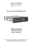
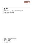
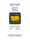
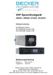
Mode S Transponder
Einblockgerät / Single Block Unit BXP 6401-X-(XX)
und Bediengerät / and Control Unit CU 6401-1-(XX)
Bedienungsanleitung
Operating Instructions
Ausgabe / Issue Januar/y 2006
Artikel-Nr. / PN 0591.823-071
Becker Flugfunkwerk GmbH • Baden-Airpark B 108 • 77836 Rheinmünster • Germany
Telefon / Telephone +49 (0) 7229 / 305-0 • Fax +49 (0) 7229 / 305-217
http://www.becker-avionics.de • e-mail: [email protected]
Bedienung/Operation XPDR Mode S
Inhaltsverzeichnis / Table of Contents
Seite / Page
1.
Wichtig ............................................................................................................................................. 4
2.
Einleitung ......................................................................................................................................... 4
2.1 Sicherheitshinweise .......................................................................................................................... 4
2.2 Liste der Abkürzungen ...................................................................................................................... 5
3.
Bedienung ........................................................................................................................................ 6
3.1 Bedien- und Anzeigeelemente .......................................................................................................... 6
3.2 Bedienungsanleitung ........................................................................................................................ 8
4.
Transponderbeschreibung .............................................................................................................. 17
4.1 Geräte-Zulassungen ....................................................................................................................... 17
5.
Systembeschreibung ...................................................................................................................... 18
6.
Technische Daten........................................................................................................................... 19
6.1 BXP 6401-X-(XX)............................................................................................................................ 19
6.2 CU 6401-1-(XX) .............................................................................................................................. 21
7.
Reparaturhinweise .......................................................................................................................... 22
7.1 Gerätehandbücher.......................................................................................................................... 22
1.
Important ........................................................................................................................................ 23
2.
Introduction..................................................................................................................................... 23
2.1 Safety information........................................................................................................................... 23
2.2 List of abbreviations........................................................................................................................ 24
3.
Operation ....................................................................................................................................... 25
3.1 Controls and indicators ................................................................................................................... 25
3.2 Operating instructions..................................................................................................................... 27
4.
Transponder description ................................................................................................................. 35
4.1 Equipment approvals ...................................................................................................................... 35
5.
System description ......................................................................................................................... 36
6.
Technical data ................................................................................................................................ 37
6.1 BXP 6401-X-(XX)............................................................................................................................ 37
6.2 CU 6401-1-(XX) .............................................................................................................................. 39
7.
Repair instructions .......................................................................................................................... 40
7.1 Equipment manuals........................................................................................................................ 40
© Copyright bei / by Becker Flugfunkwerk GmbH 77836 Rheinmünster / Germany
Alle Rechte vorbehalten. All rights reserved.
Technische Änderungen vorbehalten. Subject to technical changes.
Seite/Page 2 von/of 42
Bedienung/Operation XPDR Mode S
Abbildungen / IIlustrations
Abbildung 1:
Frontansicht BXP 6401-X-(XX) und CU 6401-1-(XX) ........................................................ 6
Abbildung 2:
Einschalt-Anzeige............................................................................................................. 8
Abbildung 3:
AI-Anzeige ....................................................................................................................... 9
Abbildung 4:
FN-Anzeige ...................................................................................................................... 9
Abbildung 5:
Flight-Level-Anzeige......................................................................................................... 9
Abbildung 6:
Fehler-Anzeige und Warnungs-Anzeige.......................................................................... 10
Illustration 1:
Front panel of BXP 6401-X-(XX) and CU 6401-1-(XX) .................................................... 25
Illustration 2:
Start-up indication .......................................................................................................... 27
Illustration 3:
AI indication ................................................................................................................... 28
Illustration 4:
FN indication .................................................................................................................. 28
Illustration 5:
Flight level indication ...................................................................................................... 28
Illustration 6:
Error indication and warning indication............................................................................ 29
Seite/Page 3 von/of 42
Bedienung/Operation XPDR Mode S
1.
Wichtig
Lesen Sie diese Bedienungsanleitung aufmerksam durch, bevor Sie den Transponder
BXP 6401-1-(XX) Class 1 bzw. den BXP 6401-2-(XX) Class 2 oder das Bediengerät CU
6401-1-(XX) in Betrieb nehmen.
Bewahren Sie diese Bedienungsanleitung sorgfältig auf. Sie enthält wichtige Sicherheitsund Bedienungsanweisungen für den Transponder und für das Bediengerät.
2.
Einleitung
Vielen Dank für den Kauf des Becker Mode S Transponders oder des Bediengerätes. Der
Transponder bzw. das Bediengerät kann im Instrumentenbrett oder in der Bedienkonsole
von Luftfahrzeugen installiert werden und ist leicht zu bedienen.
Zur vollen Nutzung der Möglichkeiten Ihres Transponders lesen Sie bitte diese
Bedienungsanleitung vollständig durch, bevor Sie mit der Bedienung beginnen. Wenn Sie
irgendwelche Fragen hinsichtlich der Bedienung des Gerätes haben, dann wenden Sie
sich an den nächst gelegenen Becker-Werksvertreter oder an den Becker-Kundendienst.
Die Hervorhebungen VORSICHT, ACHTUNG und ANMERKUNG haben folgende
Bedeutung:
VORSICHT
Ungenaues Befolgen oder Nichtbefolgen von Anweisungen oder Verfahren
kann zu Verletzungen oder tödlichen Unfällen führen.
ACHTUNG
Ungenaues Befolgen oder Nichtbefolgen von Anweisungen oder Verfahren
kann zu Fehlfunktionen oder zur Beschädigung des Gerätes führen.
ANMERKUNG Besonderheit, auf die aufmerksam gemacht werden soll.
2.1 Sicherheitshinweise
ACHTUNG:
•
Der Einbau des Mode S Transponders und des Bediengerätes in ein Luftfahrzeug
darf grundsätzlich nur durch eine autorisierte Installationsfirma (LTB) erfolgen.
Dabei sind immer die landesspezifischen Vorschriften zu beachten.
•
Die Programmierung des Adress-Modules AM 6400-1 mit der ICAO 24-bit-Adresse
des Luftfahrzeuges darf nur in der Installationsfirma (LTB) oder im Herstellerwerk
durchgeführt werden.
•
Gerät nicht einschalten, bevor Motoren bzw. Triebwerke gestartet sind. Gerät
ausschalten, bevor Motoren bzw. Triebwerke abgestellt werden.
Seite/Page 4 von/of 42
Bedienung/Operation XPDR Mode S
•
Die Nutzung des Gerätes in Umgebungstemperaturen unter -20°C und über +70°C
ist zu vermeiden.
•
Die Installationsfirma (LTB) hat sicherzustellen, dass mit dem Transponder das
entsprechende Adressmodul AM 6400-1 installiert ist und dass das Adressmodul
korrekt programmiert wurde.
2.2 Liste der Abkürzungen
AA
ADLP
AI
ALT
ATC
BIT
CBIT
CCS
CS
EASA
ELS
EHS
FAA
FL
FN
GICB
GND
ICAO
IBIT
ID
IDT
IFR
Lfz
LTB
MTL
ON
PBIT
PN
R
SBY
SEL
SI
SPI
SSR
STO
TN
VFR
XPDR
Aircraft Address, 24-bit ICAO (Luftfahrzeugadresse, 24-bit ICAO)
Avionics Data Link Processor (Luftfahrt-Datenübertragungs-Prozessor)
Aircraft Identifier (Tail Number)
Altitude or transponder ALT mode (Höhe oder Höhenübertragungsbetrieb)
Air Traffic Control (Luftverkehr-Kontrolle)
Built-In Test (Selbsttest)
Continuous Built-In Test (kontinuierlicher Selbsttest)
Company Call Sign (Fluggesellschafts-Rufzeichen)
Call Sign (Rufzeichen)
European Aviation Safety Agency
Elementary Surveillance (Grundüberwachung)
Enhanced Surveillance (erweiterte Überwachung)
Federal Aviation Administration
Flight Level (Flugebene)
Flight Number (Flugnummer)
Ground Initiated Comm-B (von der Bodenstation initiierte Übertragung)
Ground (Boden)
International Civil Aviation Organization
Initiated Built-In Test (ausgelöster Selbsttest)
Identifier (Kennzeichen)
Ident (Identifikation)
Instrument Flight Rules (Instrumentenflugregeln)
Luftfahrzeug
Luftfahrttechnischer Betrieb
Minimum Triggering Level (Auslöseschwelle)
Transponder ON mode (Transponder eingeschaltet)
Power-on Built-In Test (Einschalt-Selbsttest)
Part Number (Teilenummer)
Reply (Antwort)
Standby mode (Bereitschaftsbetrieb)
Selection (Auswahl)
Surveillance Identifier (Kennzeichen der Überwachungsanlage)
Spezieller Impuls zur Identifikation des Lfz
Secondary Surveillance Radar (Sekundär-Überwachungs-Radar)
Store (speichern)
Tail Number (Luftfahrzeug-Nummer)
Visual Flight Rules (Sichtflugregeln)
Kurzbezeichnung für Transponder
Seite/Page 5 von/of 42
Bedienung/Operation XPDR Mode S
3.
Bedienung
3.1 Bedien- und Anzeigeelemente
Abbildung 1: Frontansicht BXP 6401-X-(XX) und CU 6401-1-(XX)
Seite/Page 6 von/of 42
Bedienung/Operation XPDR Mode S
Funktion der Bedien- und Anzeigelemente:
Ref. zu
Abb. 1
Bedien- und
Anzeigelemente
Beschreibung
Funktion
A
Betriebsartenschalter
Drehwahlschalter mit 4
Raststellungen
Position OFF: Transponder ist ausgeschaltet
Position SBY: Betriebsbereitschaft ist
eingeschaltet
Position ON: Betriebsart A/S ist
eingeschaltet. Die Übertragung der
Höhen-Information wird unterdrückt
Position ALT: Betriebsart A/C/S ist
eingeschaltet und die HöhenInformation wird übertragen
B
Drehschalter
Optischer Dreh-Impulsgeber Drehschalter zur Änderung der
(Drehfunktion von C)
Einstellungen (16-stufig)
C
Taster
Drucktaste
(Druckfunktion von B)
Tastendruck bewirkt den Sprung von
Digit zu Digit (zwecks Einstellungen)
oder von einem Menü zum nächsten;
allgemein verwendet als Eingabetaste
D
IDT
Drucktaster
Aktiviert den Identifizierungsimpuls
(SPI) für ca. 18 Sekunden zusätzlich
zum Antwort-Code ; während dieser
Zeit wird „ID“ im LC-Display angezeigt
E
Display, Teil 1
2-zeilige LC-Anzeige
Anzeige der folgenden Informationen:
- Code-Anzeige in der oberen Reihe
- Flight-Level in der unteren Reihe
- versch. Infos in der unteren Reihe
- zusätzliche Anzeigen linksseitig
(siehe auch Ref. H)
F
STO
Drucktaster
Speichert die eingestellten und
geänderten Werte
G
SEL
Drucktaster
Öffnet das Menü
H
Display, Teil 2
LC-Anzeige
Anzeige von zusätzlichen Indikatoren,
(R für Reply, ID für Ident, ALT für XPDR
Betriebsart ALT oder ON für XPDR
Betriebsart ON, FL für Flight-Level)
J
VFR
Drucktaster
Aktiviert den vorgewählten VFR-Code
in der unteren Display-Zeile
Seite/Page 7 von/of 42
Bedienung/Operation XPDR Mode S
3.2 Bedienungsanleitung
A.
Einschalten des Gerätes (Vorflugkontrolle)
(1)
Bordnetz einschalten (kontrollieren, ob der Schutzschalter (circuit breaker)
eingeschaltet ist.
ACHTUNG:
Gerät nicht einschalten, bevor Motoren bzw. Triebwerke gestartet sind. Gerät
ausschalten, bevor Motoren bzw. Triebwerke abgestellt werden.
(2)
B.
Transponder mit dem Betriebsartenschalter (A) von OFF auf SBY schalten,
dabei folgt automatisch für 2 Sekunden ein Einschalttest (PBIT) des Gerätes.
Siehe auch Abschnitt B für die Inbetriebnahme.
Inbetriebnahme
Mit dem Einschalten wird das Gerät in Betrieb genommen. Die Software initialisiert
das Gerät und führt den Einschalttest (PBIT) aus. Während dieser Zeit sieht die
Display-Anzeige wie folgt aus:.
Abbildung 2: Einschalt-Anzeige
Wenn nach Ablauf des Einschalttestes keine Fehlermeldung im Display erscheint,
dann schaltet der Transponder in den vom Betriebsartenschalter (A) bestimmten
Mode.
C.
CODE-Anzeige
Der Transponder-Code wird in den Betriebsarten SBY, ON und ALT in der oberen
Display-Zeile angezeigt.
D.
Luftfahrzeugidentifikation / Flugnummer
Abhängig von den Konfigurationseinstellungen wird das Lfz-Kennzeichen (AI) oder
die Flugnummer (FN) in der unteren Display-Zeile wie folgt angezeigt:
Seite/Page 8 von/of 42
Bedienung/Operation XPDR Mode S
Abbildung 3: AI-Anzeige
Abbildung 4: FN-Anzeige
E.
Flugebene (Flight-Level)
Der Flight-Level wird in der Betriebsart ALT in der unteren Display-Zeile angezeigt
(Höhe = FL x 100 in ft):
Abbildung 5: Flight-Level-Anzeige
F.
Selbsttests des Gerätes (BITs)
Die folgenden, verschiedenen Tests sind im Transponder integriert oder können am
Transponder ausgelöst werden:
(1)
Der IBIT (Initiated Built-In Test) kann mit dem gleichzeitigen Drücken der Tasten (F)
und (G) in jeder Betriebsart aktiviert werden (ausgenommen im KonfigurationMode). Der Test startet mit dem Drücken der zweiten Taste.
Der IBIT funktioniert wie folgt in allen Betriebsarten:
Der Test startet mit allen verfügbaren Testroutinen einschließlich der Sendertestroutine. Während des Tests wird “IBIT” im Display angezeigt. Der Testablauf
dauert nicht länger als 1 Sekunde. Wenn der IBIT erfolgreich war, schaltet der
Transponder sofort zurück in die angewählte Betriebsart. Während dem IBIT
werden keine anderen Schalterbetätigungen anerkannt.
Seite/Page 9 von/of 42
Bedienung/Operation XPDR Mode S
Negative IBIT-Ergebnisse werden im Display mit “FAILURE” angezeigt. Der
Transponder kann nicht in die Betriebsarten ON oder ALT geschaltet werden, wenn
irgendein Fehler gefunden wurde.
(2)
Der CBIT (Continuous Built-In Test) arbeitet wie folgt:
Der CBIT bewirkt eine Überwachung während des Transponder-Betriebes.
Negative CBIT-Ergebnisse werden im Display mit “FAILURE” angezeigt. Der
Transponder kann nicht in die Betriebsarten ON oder ALT geschaltet werden, wenn
irgendein Fehler gefunden wurde.
(3)
Der PBIT (Power-on Built-In Test) funktioniert wie folgt:
Der Tranponder hat einen Einschalt-Selbsttest (PBIT). Während dem PBIT werden
keinen anderen Schalterbetätigungen anerkannt.
Während dem PBIT befindet sich der Transponder in der Betriebsart Standby
(SBY), dies wird aber nicht im Display angezeigt. Die Anzeige der Betriebsart im
Display erfolgt sofort nach Beendigung des PBIT.
Negative Ergebnisse werden im Display mit “FAILURE” angezeigt. Der
Transponder kann nicht in die Betriebsarten ON oder ALT geschaltet werden, wenn
irgendein Fehler gefunden wurde.
Der PBIT dauert nicht länger als 1 Sekunde. Wenn der Test erfolgreich war,
schaltet der Transponder sofort in die angewählte Betriebsart.
Abbildung 6: Fehler-Anzeige und Warnungs-Anzeige
Seite/Page 10 von/of 42
Bedienung/Operation XPDR Mode S
G.
Auswahlmodus
Um in den Auswahlmodus zu gelangen, die SEL-Taste drücken (G) und den
Schalter (B) drehen. Im Auswahlmodus werden zusätzliche Informationen in der
unteren Display-Zeile angezeigt. Einige der Daten sind veränderbar, andere sind
nur lesbar:
G.1
VFR 4096 Code - Einstellung
veränderbar; siehe Abschnitt G.2
AI
Lfz-Kennzeichen
(Lfz-Nummer)
fest; lesbar nur aus dem Adressmodul
(kann ersetzt werden durch FN)
Wenn kein gültiger AI gespeichert ist,
wird “- - - - - - - -“ angezeigt.
FN
Flugnummer oder Flug- veränderbar; siehe Abschnitt G.1,
gesellschafts-Rufzeichen kann ersetzt werden durch AI (fest)
mit Auswahl “AI DEF”
AA
Lfz-Adresse
(24-bit ICAO)
fest; lesbar nur aus dem Adressmodul
(einmalig vergebene Nr. für jedes Luftfahrzeug)
MA
max. Geschwindigkeit
fest; lesbar nur aus dem Adressmodul
AT
Lfz-Typ
fest; lesbar nur aus dem Adressmodul
CFG Konfiguration
nur im SBY-Betrieb verfügbar; siehe Abschnitt L
INS
nur im SBY-Betrieb verfügbar;
gesichert durch Passwort
Installationseinstellung
Lfz-Identifikation (AI oder FN)
mit Flugplan:
Definition aus dem Flugplan:
z.B. Flugnummer oder Fluggesellschafts-Rufzeichen
ohne Flugplan (VFR):
Lfz-Kennzeichen (Rufzeichen)
Die AI-Anzeige in der unteren Display-Zeile ist nur im Konfigurations-Menü in den
Betriebsarten SBY und ON anwählbar. Das Lfz-Kennzeichen (fest) ist in jeder
Betriebsart nach Drücken der SEL-Taste (G) und dem Drehen des Schalters (B)
sichtbar. Der Standardwert für den AI ist das Lfz-Kennzeichen, er ist im
Adressmodul gespeichert.
Wenn ein Flugplan existiert, so ist zu prüfen, welches AI-Kennzeichen verwendet
werden soll. Wenn eine Flugnummer zugeteilt wurde, so muss diese benutzt
werden. Wird ein Fluggesellschafts-Rufzeichen zugeordnet, so ist dies zu
verwenden. Zu sehen ist dies in der unteren Display-Zeile. Das AI wird im EEPROM
vom Bedienkopf gespeichert. In diesem Fall ändert sich die Anzeige von AI zu FN
(Flugnummer). Wenn das Lfz-Kennzeichen zugeteilt wird, ändert sich nichts, da
dies die Standard-Einstellung vom Adressmodul ist.
Seite/Page 11 von/of 42
Bedienung/Operation XPDR Mode S
Einstellung der Flugnummer:
(1)
Taste SEL (G) drücken, um in den Auswahlmodus zu gelangen.
(2)
Schalter (B) drehen bis der AI angezeigt wird.
(3)
Taste (C) drücken, um zur FN umzuschalten. Der Cursor steht auf dem
ersten Zeichen.
(4)
Schalter (B) drehen, um das Zeichen zu ändern.
(5)
Taste (C) drücken, um mit dem Cursor das nächste Zeichen anzuwählen.
(6)
Schritte 4 und 5 wiederholen, bis die Flugnummer eingestellt ist.
(7)
Wenn die Flugnummer aus weniger als 7 Zeichen besteht, so ist das Ende
der Nummer anzuwählen und die restlichen Stellen mit Leerzeichen
aufzufüllen.
(8)
Änderungen mit der Taste STO (F) abspeichern. Zum Verlassen der
Einstellungsprozedur ohne Abspeicherung die Taste SEL (G) drücken.
ANMERKUNG:
Das Lfz-Kennzeichen bzw. die Flugnummer besteht aus max. 7 Zeichen
(linksbündig). Striche oder Leerstellen sollen in der Nummer nicht eingeschlossen
sein. Wenn die Flugnummer aus weniger als 7 Zeichen besteht, so sind die übrig
gebliebenen Stellen an der rechten Seite mit Leerzeichen aufzufüllen.
Zurückschalten zum Standard-AI:
(1)
Taste SEL (G) drücken, um in den Auswahlmodus zu gelangen.
(2)
Schalter (B) drehen bis zur Anzeige FN=XXXXXXXX.
(3)
Taste (C) einmal drücken zur Anzeige von ”FN=AI DEF” (invertiert).
(4)
Die Einstellung AI=DEF kann mit der Taste STO (F) gespeichert werden.
Änderung der Flugnummer:
(1)
Taste SEL (G) drücken.
(2)
Schalter (B) drehen, bis FN angezeigt wird.
(3)
Taste (C) zweimal drücken, um in den FN Änderungsmodus zu gelangen.
(4)
Änderung der FN wie oben beschrieben durchführen.
Seite/Page 12 von/of 42
Bedienung/Operation XPDR Mode S
G.2
Voreinstellung des VFR-Codes
Taste SEL (G) drücken, um in den Konfigurationsmodus zu gelangen (Auswahl
wird im Display in der linken, unteren Ecke unter der Betriebsart angezeigt).
(1)
Schalter (B) drehen bis zur Display-Anzeige VFR=XXXX.
(2)
Taste (C) einmal drücken ⇒ linkes Digit vom Code ist invertiert.
(3)
Nun kann das Digit mit Schalter (B) geändert werden.
(4)
Taste (C) wieder drücken ⇒ nächstes linkes Digit vom Code ist invertiert.
(5)
Das nächste Digit kann mit Schalter (B) geändert werden.
(6)
usw. für die nächsten Digits.
(7)
Fünfter Druck auf Taste (C) ⇒ das erste Digit ist wieder invertiert.
(8)
Änderungen können jederzeit mit der Taste STO (F) gespeichert werden, in
diesem Fall wird die Invertierung gestoppt.
(9)
Ein VFR-Code, der auf diesem Wege voreingestellt wurde, kann wie in
Abschnitt I. beschrieben, aktiviert werden.
(10)
Für die Inversion ist eine Auszeit von 10 Sekunden vorgegeben, wenn
keine Aktion ausgeführt wird. Es wird nichts abgespeichert, solange die
Taste STO (F) nicht gedrückt wird.
ANMERKUNG:
Es ist möglich, das Einstellungsverfahren mit dem Druck auf die Taste SEL (G)
jederzeit zu verlassen, dann ist der angewählte Modus verfügbar. Die Anzeige SEL
im Display geht zurück auf die Anzeige der Betriebsart. Wenn die Taste STO (F)
nicht betätigt wurde, dann wird auch keine vorgenommene Änderung gespeichert.
H.
Flugbetrieb im Modus A/C/S (Antwortcode und Höhencode)
(1)
Wenn von ATC die Aufforderung kommt, einen Code zu senden, z.B.
„squawk“, dann ist der Transponder mit dem Betriebsartenschalter (A) in
Stellung ALT zu schalten.
ANMERKUNGEN:
•
Dies macht aber nur Sinn, wenn an den Transponder ein codierter
Höhenmesser angeschlossen ist. Wenn nicht, so ist der ATC mitzuteilen,
dass der Modus C nicht verfügbar ist („mode charlie not available“).
Seite/Page 13 von/of 42
Bedienung/Operation XPDR Mode S
•
(2)
In Ausnahmefällen ist die Höhenübertragung auszuschalten, d.h. der
Transponder ist mit dem Betriebsartenschalter (A) auf ON zu schalten.
Der Transponder antwortet mit dem eingestellten Code und übermiittelt der
ATC auf Modus C-Abfragen die Flughöhe des Lfz. Ein „R“ im Display links
neben dem Code signalisiert eine Transponderantwort (Reply).
ANMERKUNG:
Wenn der Code geändert werden soll, dann ist der Transponder in die
Betriebsart Standby (SBY) zu schalten. Ansonsten könnte möglicherweise
ein Code mit einer speziellen Bedeutung ausgesendet werden (siehe
Abschnitt K, z.B. Entführung eines Lfz), was unerwünschte Folgen haben
würde.
(3)
Nach Aufforderung durch ATC “squawk ident” ist die Ident-Taste (D) kurzzeitig zu drücken. Damit wird für ca. 18 Sekunden ein zusätzlicher ,spezieller
Impuls (SPI) gesendet, der eine eindeutige Identifizierung des Lfz auf dem
Radarschirm der ATC ermöglicht. Während dieser Zeit erscheint im Display
linksseitig die Anzeige „ID“.
(4)
In einem normalen Einbau wird der Blind-Encoder mit Betriebsspannung
versorgt, wenn der Transponder sich in einer der drei Betriebsarten SBY,
ON oder ALT befindet.
Ein Blind-Encoder benötigt möglicherweise eine Aufwärmzeit (bis zu einigen
Minuten). Deshalb den Transponder sofort nach dem Starten der Motoren
oder Triebwerke in Stellung SBY schalten, obwohl ein mit Halbleitern
bestückter Transponder selbst keine Aufwärmzeit benötigt.
I.
Aktivierung des VFR-Codes
(1)
Taste VFR (J) drücken. Der voreingestellte Code wird angezeigt. Nach 3
Sekunden wird der angezeigte VFR-Code aktiv und überschreibt den früher
eingestellten Code.
(2)
Durch erneutes Drücken der zuvor betätigten Taste (J) innerhalb von 3
Sekunden wird der früher eingestellte Antwortcode wieder aktiv.
ANMERKUNG:
Bei Auslieferung des Gerätes ist die VFR-Taste noch nicht mit einem Code belegt.
Deshalb erscheint bei Betätigung dieser Taste für 0,5 Sekunden “----” in der CodeAnzeige, anschließend schaltet der Transponder auf den zuvor aktiven Code
zurück.
Seite/Page 14 von/of 42
Bedienung/Operation XPDR Mode S
J.
Internes und externes Ident
Der spezielle Identifizierungssimpuls (SPI) kann durch Drücken der Taste IDT (D)
am Bedienkopf oder über den entsprechenden externen Eingang des Transponders
ausgelöst werden.
Wenn der spezielle Identifizierungsimpuls ausgelöst wurde, dann erscheint die
Anzeige “ID” im Display, solange der SPI aktiv ist.
K.
Spezielle Codierungen für Luftnotfälle
(1)
(2)
Für bestimmte Luftnotfälle wurden spezielle Codierungen festgelegt, die in
Zusammenhang mit der Art des Notfalles bestehen:
•
7500 Entführung eines Luftfahrzeuges
•
7600 Ausfall von Funkverbindungen
•
7700 Notfall an Bord, der eine unmittelbare Gefahr für das Luftfahrzeug
darstellt.
Die Code-Auswerteeinrichtungen der Radaranlagen alarmieren automatisch
die Controller an den Radarschirmen, sobald einer dieser speziellen Codes
empfangen wird.
Seite/Page 15 von/of 42
Bedienung/Operation XPDR Mode S
L.
Konfigurations-Modus
Der Konfigurations-Modus ist nur im Standby-Betrieb verfügbar. Um in den
Konfigurations-Modus zu gelangen, ist die Taste SEL (G) zu drücken und der
Schalter (B) zu drehen, bis „CFG“ in der unteren Zeile des Display erscheint.
Verfügbare Optionen sind in der folgenden Tabelle definiert.
Auswahl mit Taste (C)
Auswahl mit
Drehschalter (B)
0%
BRIGHTNESS
(nur wenn der Dimmer-Eingang …
im Installationsmenü auf „none“ 50 %
…
eingestellt ist)
100%
Merkmale
ILLUM CURVE
(nur wenn externe Beleuchtungskontrolle im Installationsmenü eingestellt ist)
VIEW CONFIG
DEVICE INFO
Speichertaste (F)
Standard
speichern
speichern
speichern
speichern
speichern
speichern der Änderung
AI IN SBY
Standard
ON
OFF
AI IN ON
Standard
ON
OFF
FL IN ALT
Standard
ON
OFF
nur Ansicht
CU VER
CORE VER
FPGA VER
DEV TYPE
SERIAL NB
nicht unterstützt
ANMERKUNG: Wenn eine Art nicht verfügbar ist, gibt es keine Anzeige in diesem Feld.
Seite/Page 16 von/of 42
Bedienung/Operation XPDR Mode S
4.
Transponderbeschreibung
Der Mode S Transponder und das Bediengerät sind bordseitige Bestandteile der
Flugsicherungskontrolle (Air Traffic Control). Sie arbeiten nach dem Sekundär-RadarPrinzip und ermöglichen der ATC die Ortung, Identifizierung und Flugverfolgung von
Luftfahrzeugen.
Der Mode S Transponder besitzt folgende Merkmale:
•
Im selektiven Modus (Mode S) kann die Bodenkontrolle den Transponder individuell
über eine spezielle ICAO-24-bit Adresse abfragen, welche eindeutig für das
entsprechende Luftfahrzeug vergeben wurde.
•
Unterstützung des SI-Codes
•
Verfügbare Register für die Grundüberwachung (ELS) und die erweiterte
Überwachung (EHS)
•
Extented Squitter-Übertragung
•
Fähigkeit, zusätzliche Daten zu übertragen
Inhärente Funktionen:
•
Mode A - Betrieb , wobei der am Transponder eingestellte 4096-Code als Antwort
auf die Abfrage einer Bodenstation zurückgesendet wird.
•
Mode C - Betrieb, wobei zusätzlich zu den Möglichkeiten von Mode A noch die
verschlüsselte Flughöhe übertragen wird. Die Flughöhe wird durch den
entsprechenden Flight-Level (Höhe in 100 ft-Schritten) im Display angezeigt. Der
Höhencode wird dem Transponder von einem codierten Höhenmesser oder BlindEncoder zugeführt.
•
Ein spezieller Identifizierungsimpuls (SPI) kann durch Drücken der IDT-Taste im
A/C-Betrieb und im Mode S aktiviert werden.
•
Selbsttests (BITs). Im Transponder integriert sind ein automatischer Einschalttest
(PBIT), ein am Frontpanel auslösbarer Selbsttest (IBIT) und ein kontinuierlicher
Test (CBIT) während des Betriebes.
4.1 Geräte-Zulassungen
EASA.210.322
* FAA
ETSO-2C112a
TSO-C112
* anstehend
Seite/Page 17 von/of 42
Bedienung/Operation XPDR Mode S
5.
A.
Systembeschreibung
Mode A/C SSR
SSR Mode A/C nutzen den im Luftfahrzeug eingebauten Transponder, um auf Abfragen
der Bodenstation mit einem 4096-Code (Mode A) zu antworten und die Höheninformation
(Mode C) in 100 ft. -Schritten zu übertragen.
In Mode A wird der, von der ATC angeforderte Code von der Lfz-Besatzung im Cockpit
über das Frontpanel des Transponders eingegeben.
Die Position des Luftfahrzeuges in Bezug auf die Bodenstation wird von den, bei XPDRAntworten gemachten Bereichs- und Azimut-Messungen bestimmt.
B.
Mode S SSR
Mode S ist eine Erweiterung des gegenwärtigen SSR, das die selektive Adressierung von
einzelnen Luftfahrzeugen erlaubt. Außerdem können zusätzliche Daten vom Luftfahrzeug
zum Boden übertragen werden.
Jedem, mit einem Mode S Transponder ausgerüsteten Luftfahrzeug wird eine eindeutige
24-bit ICAO Lfz-Adresse zugeteilt. Mit Nutzung der selektiven Abfragefähigkeit sind SSR
Mode S-Sensoren in der Lage, ein Luftfahrzeug über seine eindeutige 24-Bit Lfz-Adresse
zuerst zu bestimmen und dann selektiv abzufragen. Dies verbessert die Fähigkeit der
ATC, ein Lfz in der Luft als auch am Boden zu überwachen, bedeutend.
Der Fortschritt von Mode S liegt in der Verwendung der selektiven Adressierung von
Luftfahrzeugen, was technische Vorteile gegenüber dem konventionellen Sekundär-Radar
bietet, so z. B. reduzierte FRUIT und Interferenzen.
Der Mode S Transponder unterstützt den Überwachungs-Kennzeichen-Code (SI) mit
temporärer, selektiver Aussperrung von bestimmten Abfragen auf Anweisung.
Weiterhin unterstützt der Mode S Transponder den Flug-Status (Luft oder am Boden) und
die Flughöhe in 25 ft.- Schritten, abhängig vom Raster der Datenquelle.
C.
Squitter
Dieser Mode S Transponder ist in der Lage, erfasste Squitter und erweiterte Squitter zu
übertragen. Squitter ist die Aussendung eines vorgegebenen Transponder-Formates,
ohne die Notwendigkeit einer Abfrage.
D.
Höhenmessausrüstung
Es ist erforderlich, dass der Höhenmesser einen Kodierer für die Höhenauswertung
beinhaltet. In den meisten Fällen wird deshalb entweder ein Luftdatencomputer oder ein
kodierter Höhenmesser eingesetzt werden.
Seite/Page 18 von/of 42
Bedienung/Operation XPDR Mode S
6.
Technische Daten
6.1 BXP 6401-X-(XX)
Versorgungsspannung
10.0 V bis 33.0 V DC
typische Stromaufnahme bei
50 Mode S Antworten / sec. + Squitter:
0,37 A bei 14 V (Beleuchtung aus)
0,22 A bei 28 V (Beleuchtung aus)
0,43 A bei 14 V (Beleuchtung max.)
0,25 A bei 28 V (Beleuchtung max.)
im Standby-Betrieb:
0,22 A bei 14 V (Beleuchtung aus)
0,14 A bei 28 V (Beleuchtung aus)
0,28 A bei 14 V (Beleuchtung max.)
0,16 A bei 28 V (Beleuchtung max.)
Panelbeleuchtung
Dimmer-Eingang
Beleuchtungsstromaufnahme
max. 1 mA bei 28V
Beleuchtungsfarbe (Display + Tasten) weiß
Serielle Schnittstelle
RS 422
Datenübertragungsfähigkeit
255 GICB Register
Einschaltzeit
2 sec. (einschließlich interner Selbsttest)
Interne Absicherung
F5A
Externe Absicherung
5 A (Class 1)
3 A (Class 2)
Betriebstemperaturbereich
- 20° C bis + 55° C (kurzzeitig + 70° C)
Lagertemperaturbereich
- 55° C bis+ 85° C
Betriebshöhe
50000 ft. max. (Class 1)
15000 ft. max. (Class 2)
Betriebsarten
Mode A/C/S, abhängig von der Abfrage
Mode S
Class 1 oder 2, Level 2es
- erweiterte Squitter - Fähigkeit
- Überwachungskennzeichen (SI-Code)
Seite/Page 19 von/of 42
Bedienung/Operation XPDR Mode S
Empfangsfrequenz
1030 MHz ± 0,1 MHz (Mode A/C)
1030 MHz ± 0,01 MHz (Mode S)
Empfindlichkeit (MTL)
- 74 dBm ± 3 dB (für 90 % Antwortrate
in Mode A/C und 99 % in Mode S)
Sendefrequenz
1090 MHz ± 1 MHz
Sendeleistung (Class 1)
≥ 125 W (+ 21 dBW) am Antennenfußpunkt und ≥ 250 W am Geräteausgang
Sendeleistung (Class 2)
≥ 70 W (+ 18.5 dBW) am Antennenfußpunkt und ≥ 140 W am Geräteausgang
Antwortcode (Mode A)
ICAO Codierungssystem mit 4096
Antwortmöglichkeiten (Oktalcode)
Höhencode (Mode C)
ICAO Codierungssystem 100 ft. - Schritte
von -1000 bis 62700 ft.
Höhencode (Mode S)
25 ft. oder 100 ft. - Schritte
(abhängig von der Quelle)
Mechanische Abmesssungen:
- Frontplatte
61,3 x 61,3 mm (H x B)
(2.413 x 2.413 inch)
- Instrumentendurchmesser
58 mm (2¼ inch)
- Gehäusetiefe
ohne Antennenbuchse
mit Antennenbuchse
mit Adressmodul
Gewicht
192 mm (7.599 inch)
206 mm (8.110 inch)
239 mm (9.409 inch)
ca. 0,8 kg
Seite/Page 20 von/of 42
Bedienung/Operation XPDR Mode S
6.2 CU 6401-1-(XX)
Versorgungsspannung
10,0 bis 33,0 V DC
typische Stromaufnahme
0,045 A bei 14 V (Beleuchtung aus)
0,034 A bei 28 V (Beleuchtung aus)
0,138 A bei 14 V (Beleuchtung max.)
0,080 A bei 28 V (Beleuchtung max.)
Panelbeleuchtung
Dimmer-Eingang
Beleuchtungsstromaufnahme
max. 1 mA bei 28 V
Beleuchtungsfarbe (Display + Tasten) weiß
Steuerungs-Schnittstelle
RS 422
Einschaltzeit
2 sec. (einschließlich internem Selbsttest)
Interne Absicherung
F1A
Externe Absicherung
1A
Betriebshöhe
50000 ft. max.
Betriebstemperaturbereich
- 20° C bis + 55° C (kurzzeitig + 70° C)
Lagertemperaturbereich
- 55° C bis + 85° C
Mechanische Abmessungen:
- Frontplatte
61,3 x 61,3 mm (H x B)
(2.413 x 2.413 inch)
- Instrumentendurchmesser
58 mm (2¼ inch)
- Gehäusetiefe
65 mm (2.559 inch)
Gewicht
0,22 kg
Seite/Page 21 von/of 42
Bedienung/Operation XPDR Mode S
7.
Reparaturhinweise
Sollte ein Gerätefehler auftreten, so wenden Sie sich bitte an den nächst gelegenen BeckerWerksvertreter, Händler oder an den Becker-Zentralkundendienst. Die ausgefüllte
Fehlerbeschreibung verkürzt die Reparaturzeiten und senkt somit die entstehenden Kosten.
Diese Bedienungsanleitung ersetzt nicht die nachstehend aufgeführten Gerätehandbücher
(Manuals).
7.1 Gerätehandbücher
zu beziehen vom Hersteller oder vom Becker-Werksvertreter:
BXP 6401-X-(XX) Installation and Operation
BXP 6401-X-(XX) Maintenance and Repair
CU 6401-1-(XX) Installation and Operation
CU 6401-1-(XX) Maintenance and Repair
BXP 6402-XR-(XX) Installation and Operation
BXP 6402-XR-(XX) Maintenance and Repair
Control Interface Protocol BXP 6402-XR-(XX)
Data Transfer Interface Protocol BXP 640X-XX-(XX)
Seite/Page 22 von/of 42
Artikel-Nr. 0584.053-071
Artikel-Nr. 0584.061-071
Artikel-Nr. 0584.096-071
Artikel-Nr. 0584.101-071
Artikel-Nr. 0584.071-071
Artikel-Nr. 0584.088-071
Artikel-Nr. 0590.241-071
Artikel-Nr. 0590.258-071
Bedienung/Operation XPDR Mode S
1.
Important
Please read these operating instructions carefully before operating the single block
transponders BXP 6401-1-(XX) class 1, BXP 6401-2-(XX) class 2 and the control unit CU
6401-1-(XX).
Keep these operating instructions carefully. They contain important safety and operating
instructions for the Mode S transponder and the control unit .
2.
Introduction
Thank you for purchasing the Becker ATC Mode S transponder or control unit. The
transponder and the control unit respectively can be installed in the instrument panel and
is easy to operate.
To fully utilise the capabilities of your transponder, please read the operating instructions
carefully before you start operating the set.
If you have any questions regarding the operation of the transponder, please get in touch
with your nearest Becker Dealer or with the Becker Customer Service.
The WARNING, CAUTION and NOTE highlights have the following meanings:
WARNING
Failure to comply, or incorrect compliance, with these instructions or
procedures can lead to injuries or fatal accidents.
CAUTION
Failure to comply, or incorrect compliance, with these instructions or
procedures can lead to malfunctions or to the damage to equipment.
NOTE
Feature to which attention should be drawn.
2.1 Safety information
CAUTIONS:
•
The installation of the Mode S transponder into an aircraft may be carried out only
by an authorized installation company. The country specific regulations always have
to be observed.
•
The programming of the address module AM 6400-1 with the ICAO 24-bit address
of the aircraft must be carried out only at an installation company or in the
manufacturer factory.
•
Do not switch on the unit before the aircraft engines are started. Switch off the unit
before the engines are shut down.
Seite/Page 23 von/of 42
Bedienung/Operation XPDR Mode S
•
Do not operate the unit under ambient temperatures below -20°C and above +70°C.
•
The installation company has to make sure that the corresponding address module
AM 6400-1 is installed with the transponder and that the address module is
programmed correctly.
2.2 List of abbreviations
AA
ADLP
AI
ALT
ATC
BIT
CBIT
CCS
CS
EASA
ELS
EHS
FAA
FL
FN
GICB
GND
ICAO
IBIT
ID
IDT
IFR
MTL
ON
PBIT
PN
R
SBY
SEL
SI
SPI
SSR
STO
TN
VFR
XPDR
Aircraft Address (24-bit ICAO)
Avionics Data Link Processor
Aircraft Identifier (tail number)
Altitude or transponder ALT mode
Air Traffic Control
Built-In Test
Continuous Built-In Test
Company Call Sign
Call Sign
European Aviation Safety Agency
Elementary Surveillance
Enhanced Surveillance
Federal Aviation Administration
Flight Level
Flight Number
Ground Initiated Comm-B
Ground
International Civil Aviation Organization
Initiated Built-In Test
Identifier
Ident (Identification)
Instrument Flight Rules
Minimum Triggering Level
Transponder ON mode (without altitude transmission)
Power-on Built-In Test
Part Number
Reply
Standby mode
Selection
Surveillance Identifier
Special Position Identification Pulse
Secondary Surveillance Radar
Store
Tail Number
Visual Flight Rules
Transponder
Seite/Page 24 von/of 42
Bedienung/Operation XPDR Mode S
3.
Operation
3.1 Controls and indicators
Illustration 1: Front panel of BXP 6401-X-(XX) and CU 6401-1-(XX)
Seite/Page 25 von/of 42
Bedienung/Operation XPDR Mode S
Function of controls and indicators:
Ref. to Controls and
illustr. 1 Indicators
Description
Function
A
Rotary switch with 4
positions
OFF position: Transponder is switched
off
Mode selector
SBY position: Standby mode is
switched on
ON position: Mode A/S is switched on.
Transmission of altitude information is
suppressed
ALT position: Mode A/C/S is switched
on and the altitude information is
transmitted
B
Rotary switch
Rotary optical encoder
(rotary mode of C)
Rotary switch to change settings
(16 steps per turn)
C
Button
Push-button
(mode of B)
Push to jump from digit to digit for
settings or from one menu to the next;
generally used as an enter key
D
IDT
Push-button
Activates the Special Identifier (SPI) in
addition to the reply code for approx. 18
seconds; during this time “ID” appears
in the LC display
E
Display, part 1
2-line LCD display
Displays the following information:
- code indication in the top row
- flight level in the bottom row
- various information in the bottom row
- additional indicators on the left side
(see Ref. H)
F
STO
Push-button
Stores the selected values to the
settings
G
SEL
Push-button
Opens the menu
H
Display, part 2
LCD indicators
Displays additional indicators, (R for
reply, ID for Ident, ALT for XPDR ALT
mode or ON for XPDR ON mode, FL for
flight level)
J
VFR
Push-button
Activates VFR code in the upper row of
the display
Seite/Page 26 von/of 42
Bedienung/Operation XPDR Mode S
3.2 Operating instructions
A.
Switching on the unit (pre-flight check)
(1)
Check that the circuit breaker is set and switch on the aircraft power supply.
CAUTION:
Do not switch on the unit before the aircraft engines are started. Switch off the unit
before the engines are shut down.
(2)
B.
Using mode switch (A), switch the transponder from OFF to SBY. A Power-on Built-In Test (PBIT) then follows automatically for 1 second.
Start-up see also section B.
Start-up
On power-up, the device starts. The software initiates circuits and performs PBIT.
During that time the display looks as follows.
Illustration 2: Start-up indication
After the PBIT has elapsed and no error-message is shown in the display, the
transponder switches to the mode set by the mode switch (A).
C.
CODE display
Transponder’s code is displayed in the top line in modes SBY, ON and ALT.
D.
Aircraft identification / Flight number
Depending on the configuration settings, the Aircraft Identification (AI) or Flight
Number (FN) is displayed in the bottom line as follows:
Seite/Page 27 von/of 42
Bedienung/Operation XPDR Mode S
Illustration 3: AI indication
Illustration 4: FN indication
E.
Flight level
Flight level is displayed in ALT mode in the bottom line of the display (altitude = FL x
100 in ft):
Illustration 5: Flight level indication
F.
Selftests of the unit (BITs)
The following different tests are integrated in the transponder or can be triggered at the
transponder:
(1)
The IBIT (Initiated Built-In Test) can be activated in any mode (excluding the
configuration mode) with the push of (F) and (G) at the same time. The action
starts with the leading edge of the second pushed button.
The IBIT works as follows in all modes:
The test starts with all available test routines including the transmitter test routine.
During the test, “IBIT” is indicated on the display. The test takes not longer than 1
second. If the IBIT was successful, the XPDR switches immediately into the chosen
operating mode. During the IBIT any action from other switches is not recognized.
Seite/Page 28 von/of 42
Bedienung/Operation XPDR Mode S
Negative results of the IBIT are indicated on the display with “FAILURE”. The
transponder may be not switched into ON or ALT mode if any failure was
found.
(2)
The CBIT (Continuous Built-In Test) works as follows:
The continuous BIT acts as a kind of watchdog during operation. Negative results of
the CBIT are indicated on the display with “FAILURE”. In this case the
transponder may be not switched into ON or ALT mode if any failure was found.
(3)
The PBIT (Power-on Built-In Test) works as follows:
The XPDR has a power-on BIT after switching on. During the PBIT any actions
from other switches are not accepted.
During the PBIT the XPDR is in the SBY mode but this is not indicated on the
display. The operating mode indication on the display starts immediately after
finalisation of the PBIT.
Negative results are indicated on the display with “FAILURE”. The transponder
may be not switched into ON or ALT mode if any failure was found.
The PBIT takes not longer than 1 second. If the test was successful, the XPDR switches immediately into the chosen operating mode.
Illustration 6: Error indication and warning indication
Seite/Page 29 von/of 42
Bedienung/Operation XPDR Mode S
G.
Selection mode
Press SEL button (G) and rotate encoder (B) for selection. In selection mode
additional information is displayed in the bottom line of the display. Some of the
data are editable, some are read only:
G.1
VFR 4096 code presetting
editable; see section G.2
AI
Aircraft Identifier
(Tail Number)
fixed; read only from address module
(can be replaced by FN)
If no valid AI is stored, “- - - - - - - -“ is displayed.
FN
Flight Number or
Company Call Sign
editable; see section G.1,
can be replaced by AI (fixed) by selecting “AI DEF”
AA
Aircraft Address
(24-bit ICAO)
fixed; read only from address module
(unique number for each aircraft)
MA
Maximum Airspeed
fixed; read only from address module
AT
Aircraft Type
fixed; read only from address module
CFG Configuration
available in SBY mode only; see section L
INS
available in SBY mode only;
protected by password
Installation setup
Aircraft Identification (AI or FN)
With flight plan:
The definition out of the flight plan:
e.g. Flight Number or Company Call Sign
Without flight plan (VFR): Tail Number (Call Sign)
The indication of AI in the bottom line of the display is in mode SBY and ON only if
selected in configuration menu. The Aircraft Identifier (fixed) is available in any
mode after pressing SEL button (G) and turning the rotary encoder (B). The default
value for AI is the Tail Number of the aircraft and is stored in the Address Module.
If a flight plan exists, it has to be checked, which AI has to be used. If a Flight
Number is assigned it has to be entered. If a Company Call Sign is mentioned, this
has to be entered. To enter it see below. It will be stored in the EEPROM of the
control head. In this case the indication on the display changes to FN (Flight
Number). If the Call Sign (Tail Number) is mentioned, no change, as it is the default
setting from the Address Module.
Seite/Page 30 von/of 42
Bedienung/Operation XPDR Mode S
Setting the flight number:
(1)
Press SEL button (G) to enter the select mode.
(2)
Rotate (B) until AI is displayed.
(3)
Push (C) to switch to FN. The cursor is set on the first character.
(4)
Rotate (B) to change this character.
(5)
Push (C) to set the cursor to the next character.
(6)
Repeat steps 4 and 5 until the flight number is entered.
(7)
If the flight number consists of less than 7 characters, put a space at the end
to fill the remaining characters with spaces.
(8)
Store the changes with STO button (F). For leaving the setting procedure
without storing, push the SEL button (G).
NOTE:
Aircraft Identifier / Flight Number consists of max. 7 characters (on the left-hand side
oriented). No dashes or spaces shall be included. If the FN consists of less than 7
characters, the remaining characters on the right side shall be filled with spaces.
Switching back to default AI:
(1)
Press SEL button (G) to enter the select mode.
(2)
Rotate (B) to the indication FN=XXXXXXXX.
(3)
First push on (C) indicates ”FN=AI DEF” (inverted).
(4)
Can be set to AI=DEF with STO button (F).
Changing the flight number:
(1)
Press SEL button (G).
(2)
Rotate (B) until FN is displayed.
(3)
Push (C) twice to enter the FN editing mode.
(4)
Change the FN as described above.
Seite/Page 31 von/of 42
Bedienung/Operation XPDR Mode S
G.2
VFR code presetting
Press the SEL button (G) to get into configuration mode (selection is indicated in
the left bottom corner of the display under the operating mode indication).
(1)
Rotate (B) to the indication VFR=XXXX.
(2)
First push to button (C) ⇒ left digit of the code is inverted.
(3)
Now the digit can be changed with (B).
(4)
Second push to button (C) ⇒ next left digit of the code is inverted.
(5)
The next digit can be changed with (B)
(6)
and the same for next digits.
(7)
Fifth push to button (C) ⇒ again first digit is inverted.
(8)
Changes can be stored with STO button (F) at any time, inversion stops
in this case.
(9)
A VFR code that was preset in this way can be activated as described in
chapter I.
(10)
A timeout for inversion (10 sec) is introduced if no action happens. Nothing
stored, as long as (F) is not pressed.
NOTE:
It is possible to leave the setting procedure with SEL button (G) at any time and the
chosen mode is available then. Indication SEL on the display changes back to
mode indication. If STO button (F) was not used, no change has been stored.
H.
Flight operation in Mode A/C/S (reply code and altitude code)
(1)
When ATC requests the transmission “squawk”, switch the transponder to
ALT using mode switch (A).
NOTES:
•
This only makes sense if the transponder is connected to a coding
altimeter. If not, tell ATC that you do not have mode C (“mode charlie not
available”).
•
In exceptions the altitude has to be turned off, i.e. switch the transponder
to ON using mode switch (A).
Seite/Page 32 von/of 42
Bedienung/Operation XPDR Mode S
(2)
The transponder replies using the selected Code and in response to mode C
interrogation it transmits the altitude of the aircraft to ATC. A “R” on the left
next to the Code on the display signals the transponder replies.
NOTE:
Switch the transponder to Stand-by (SBY), if the Code has to be changed.
Otherwise if could happen that a Code with a special meaning (see chapter
K, e.g. highjack) will be transmitted and unwanted actions could take place.
(3)
After a “squawk ident” request from ATC, press Ident button IDT (D)
briefly. This transmits an additional special pulse (SPI) for approx. 18
seconds, which enables the aircraft to be clearly identified on the radar
screen of the controller. “ID” appears on the left side in the LC display during
this time.
(4)
In a normal installation the blind encoder is powered if the transponder is
switched in one of the three modes SBY, ON or ALT.
A blind encoder possibly needs a warm-up time (sometimes several
minutes).
Therefore, although the solid state transponder needs no warm-up time, turn
the transponder to SBY immediately after starting the engine.
I.
VFR code activation
(1)
Press the VFR push-button (J). The preselected code is then displayed.
After 3 seconds, the displayed code gets active and overwrites the previously-set reply code.
(2)
Pressing push-button (J) again within 3 seconds reactivates the previously-set reply code.
NOTE:
When the unit is delivered, the VFR button is not assigned a code. This means that
if this button is pressed for 0.5 seconds, “----” is shown in the code display and the
transponder then switches back to the previously-active code.
J.
Internal and external Ident
The special identifier pulse (SPI) can be triggered by pressing “IDT” button on the
control panel or from external input located on the transponder.
If special identifier pulse has been triggered, then “ID” is displayed on the display
as long as SPI is active.
Seite/Page 33 von/of 42
Bedienung/Operation XPDR Mode S
K.
Special codings for air emergency
(1)
(2)
L.
Special codings, which depend on the type of incident, are stipulated for
certain air emergencies:
•
7500 Hijacking
•
7600 Loss of communications
•
7700 Emergency on board which constitutes an immediate danger to the
aircraft
The code evaluation devices of the radar systems automatically alarm the
controllers at the radar screens immediately if one of these special codes is
received.
Configuration mode
The configuration mode is available from SBY mode only. To get into configuration
mode press button SEL (G), turn rotary encoder (B) until “CFG” appears in the
bottom row of the display. Available options are defined in the following table.
Select with push-button (C)
BRIGHTNESS
(only if dimming input is set to
“none” in installation menu)
ILLUM CURVE
(only if external illumination
control is set in the installation
menu)
VIEW CONFIG
DEVICE INFO
Select with rotary
switch (B)
0%
…
50 %
…
100%
Characteristics
Store button (F)
default
store
store
store
store
store
store to change
AI IN SBY
default
ON
OFF
AI IN ON
default
ON
OFF
FL IN ALT
default
ON
OFF
view only
CU VER
CORE VER
FPGA VER
DEV TYPE
SERIAL NB
NOTE: If no type is available, this field indicates nothing.
Seite/Page 34 von/of 42
not supported
Bedienung/Operation XPDR Mode S
4.
Transponder description
The Mode S transponder and the control unit are the airborne components of the Air
Traffic Control (ATC). It functions in accordance with the secondary radar principle and
allows air traffic control to locate, identify and track aircraft.
The Mode S transponder provides the following features:
•
In the selective mode (Mode S), the Ground Control can interrogate the transponder
individually using the ICAO-24-bit address, which is unique to the particular aircraft.
•
Support of the SI code (Surveillance Identifier)
•
Register capability for elementary surveillance (ELS) and enhanced surveillance
(EHS)
•
Extended squitters transmission
•
Data link capability
Inherent features:
•
Mode A - in this mode, the 4096 character code set on the control head is sent as a
reply to interrogation from a ground station.
•
Mode C - in this mode, the encoded altitude is sent in addition to the possibilities of
mode A. The corresponding flight level to the altitude is indicated on the display,
delivered by encoding altimeter or blind encoder to the unit.
•
A special identifier pulse (SPI) can be activated by pressing the IDT button in Mode
A/C and Mode S.
•
Selftests (BITs). The Initiated Built-In Test (IBIT), the Continuous Built-In Test
(CBIT) and the Power-on Built-In Test (PBIT) are integrated in the transponder.
4.1 Equipment approvals
EASA.210.322
* FAA
ETSO-2C112a
TSO-C112
* Pending
Seite/Page 35 von/of 42
Bedienung/Operation XPDR Mode S
5.
A.
System description
Mode A/C SSR
SSR Mode A/C uses the aircraft transponder to respond to interrogations from the ground
to provide a 4096-code identity code (Mode A) and pressure altitude information, in 100
feet increments (Mode C).
The mode A code is entered by aircrew via a transponder control panel in the cockpit.
Mode C pressure altitude information is derived from an encoding altimeter or blind
encoder.
The plan position of the aircraft, with respect to the ground interrogator, is determined from
range and azimuth measurements made on the transponder replies.
B.
Mode S SSR
Mode S is an extension of current SSR, which permits selective addressing of individual
aircraft. Additional data may be also extracted from the aircraft.
Each Mode S equipped aircraft is assigned a unique ICAO 24-bit aircraft address. Using
the selective interrogation capability of Mode S, SSR Mode S sensors are able to first
acquire and then selectively interrogate a specific aircraft via its unique 24-bit aircraft
address. This significantly improves the ability of ATC to monitor and guide an aircraft,
airborne as well as on the ground.
The feature of Mode S resides in the use of selective addressing of aircraft which offers
technical advantages over conventional Secondary Surveillance Radar, such as reducing
FRUIT and garbling.
The Mode S transponder supports the Surveillance Identifier (SI) code with temporary
selective lockout of specific interrogators on command.
Furthermore, the Modes S transponder supports the flight status (airborne or on the
ground) and the flight level, in 25 foot increments depending on the resolution of the data
source.
C.
Squitter
This Mode S transponder is capable of transmitting acquisition squitters and extended
squitters. Squitter is a transmission of a specified transponder format without the need to
be interrogated.
D.
Altitude measuring equipment
The altitude measuring equipment is required to drive an encoder for the purpose of
altitude reporting, therefore in most cases the altitude measuring equipment will be either
an air data computer, or an encoding altimeter.
Seite/Page 36 von/of 42
Bedienung/Operation XPDR Mode S
6.
Technical data
6.1 BXP 6401-X-(XX)
Supply voltage
10.0 V to 33.0 V DC
Typical consumption
50 mode S replies/sec. + squitter:
0.37 A at 14 V (illumination off)
0.22 A at 28 V (illumination off)
0.43 A at 14 V (illumination max.)
0.25 A at 28 V (illumination max.)
in standby mode:
0.22 A at 14 V (illumination off)
0.14 A at 28 V (illumination off)
0.28 A at 14 V (illumination max.)
0.16 A at 28 V (illumination max.)
Panel illumination
control input
Illumination control current
max. 1 mA at 28V
Illumination color (display and buttons) white
Serial interfaces
RS 422
Data link capability
255 GICB registers
Power-up time
2 s (including internal self-test)
Internal fuse protection
F5A
External fuse protection
5 A (class 1)
3 A (class 2)
Operating temperature range
- 20° C to + 55° C (short-time + 70° C)
Storage temperature range
- 55° C to + 85° C
Operating altitude
50000 ft. max. (class 1)
15000 ft. max. (class 2)
Operating modes
Mode A/C/S,
depending on interrogation
Mode S
Class 1 or 2, Level 2es
- extended squitter capability
- surveillance identifier (SI code)
Seite/Page 37 von/of 42
Bedienung/Operation XPDR Mode S
Receive frequency
1030 MHz ± 0.1 MHz (mode A/C)
1030 MHz ± 0.01 MHz (mode S)
Sensitivity (MTL)
- 74 dBm ± 3 dB (for 90 % reply rate in
mode A/C and 99 % in mode S)
Transmit frequency
1090 MHz ± 1 MHz
Transmit power (class 1)
≥ 125 W (+ 21 dBW) at antenna end
terminal and ≥ 250 W at unit output
Transmit power (class 2)
≥ 70 W (+ 18.5 dBW) at antenna end
terminal and ≥ 140 W at unit output
Reply code (mode A)
ICAO coding system with 4096
pulse reply possibilities (octal code)
Altitude code (mode C)
ICAO coding system 100 ft. steps
from -1000 to 62700 ft.
Altitude code (mode S)
25 ft. or 100 ft. steps
(depending on source)
Mechanical dimensions :
- Front panel
61.3 x 61.3 mm (H x W)
(2.413 x 2.413 inch)
- Instrument size diameter
58 mm (2¼ inch)
- Case depth
without antenna socket
with antenna socket
with address module
Weight
192 mm (7.599 inch)
206 mm (8.110 inch)
239 mm (9.409 inch)
approx. 0.8 kg (1.764 lb)
Seite/Page 38 von/of 42
Bedienung/Operation XPDR Mode S
6.2 CU 6401-1-(XX)
Supply voltage
10.0 to 33.0 V DC
Typical consumption
0.045 A at 14 V (illumination off)
0.034 A at 28 V (illumination off)
0.138 A at 14 V (illumination max.)
0.080 A at 28 V (illumination max.)
Panel illumination
control input
Illumination control current
max. 1 mA at 28 V
Illumination color (display and buttons) white
Control interface
RS 422
Power-up time
2 s (including internal self-test)
Interernal fuse protection
F1A
External fuse protection
1A
Operating altitude
50000 ft. max.
Operating temperature range
- 20° C to + 55° C (short-time + 70° C)
Storage temperature range
- 55° C to + 85° C
Mechanical dimensions:
- Front panel
61.3 x 61.3 mm (H x W)
(2.413 x 2.413 inch)
- Instrument size diameter
58 mm (2¼ inch)
- Case depth
65 mm (2.559 inch)
Weight
0.22 kg (0.485 lb)
Seite/Page 39 von/of 42
Bedienung/Operation XPDR Mode S
7.
Repair instructions
If an equipment fails, the unit may be send to a Becker Dealer or the Becker customer
service together with a description of the fault. The completed fault description shortens the
repair times and hence lowers the resultant costs.
These operating instructions do not replace the equipment manuals listed below.
7.1 Equipment manuals
to be purchased from the manufacturer or Becker Dealer:
BXP 6401-X-(XX) Installation and Operation
BXP 6401-X-(XX) Maintenance and Repair
CU 6401-1-(XX) Installation and Operation
CU 6401-1-(XX) Maintenance and Repair
BXP 6402-XR-(XX) Installation and Operation
BXP 6402-XR-(XX) Maintenance and Repair
Control Interface Protocol BXP 6402-XR-(XX)
Data Transfer Interface Protocol BXP 640X-XX-(XX)
Seite/Page 40 von/of 42
Article-No. 0584.053-071
Article-No. 0584.061-071
Article-No. 0584.096-071
Article-No. 0584.101-071
Article-No. 0584.071-071
Article-No. 0584.088-071
Article-No. 0590.241-071
Article-No. 0590.258-071
Bedienung/Operation XPDR Mode S
Fehlerbeschreibung
Gerätetyp: ………………………………………… Seriennummer: ……………………
Lfz-Typ: ………………………………………………………………………………………
Kurze Beschreibung des Fehlers:
…………………………………………………………………………………………………
…………………………………………………………………………………………………
………………….………………………………………………………………………………
…………………………………………………………………………………………………
…………………………………………………………………………………………………
…………………………………………………………………………………………………
………………………………………………………………………………………………….
Tritt der Fehler nur zeitweise auf, so bitten wir um folgende Angaben:
Der Fehler erscheint erst nach einer Betriebszeit von . . . . . Minuten.
Der Fehler tritt nur bei bestimmten Umweltbedingungen auf:
bei Kälte
bei Wärme
bei Feuchte
bei Vibrationen
Der Fehler ist drehzahlabhängig und tritt über/unter . . . . . . . . U/min auf.
Für Rückfragen erreichen Sie mich unter folgender Adresse:
……………………………………………………..……
…………………………………………………………..
Zwischen 8 Uhr und 16 Uhr bin ich
unter folgender Telefonnummer
erreichbar:
…………………………………………………………gesch.: …………………………………….
…………………………………………………………privat: …………………………………….
Seite/Page 41 von/of 42
Bedienung/Operation XPDR Mode S
Fault description
Unit type: …………………………………………… Serial number: ……………………
Aircraft type: …………………………………………………………………………………
Brief description of the fault:
…………………………………………………………………………………………………
…………………………………………………………………………………………………
………………….………………………………………………………………………………
…………………………………………………………………………………………………
…………………………………………………………………………………………………
…………………………………………………………………………………………………
………………………………………………………………………………………………….
Should the fault only occur sporadically, please answer the following questions:
The fault occurs after . . . . . minutes of operation.
The fault occurs under the following environmental conditions:
low temperature
high temperature
high humidity
vibration
The fault is engine speed-dependent and occurs above/below . . . . . . . . rpm.
Should any problem arise, I may be contacted under the following address:
……………………………………………………..……
…………………………………………………………..
I am available between 8 a.m.
and 4 p.m. under the following
telephone number:
…………………………………………………………office:
…………………………………….
…………………………………………………………private: …………………………………….
Seite/Page 42 von/of 42