1
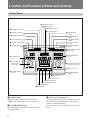
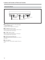
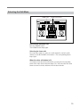
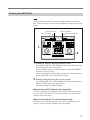
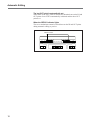
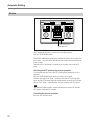
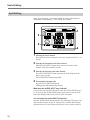
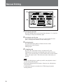
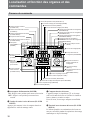
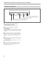
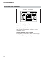
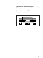
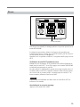
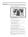
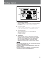
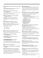
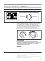
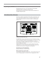
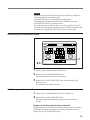
3 SYNCHRO (Synchronization) selector
Selects the way to synchronize by frame pulse.
ON/CF: This unit counts color frames to synchronize
the player and the recorder.
ON: Synchronizes the recorder and the player
regardless of the color frame.
OFF: Does not control synchronization.
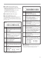
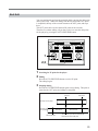
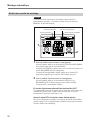
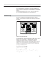
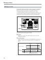
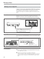
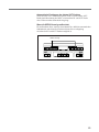
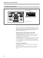
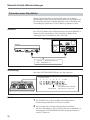
Right side
ON
Bit
6
5
4
3
2
1
0
Bit
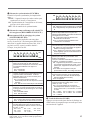
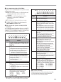
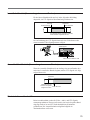
Maximum preroll time is set. When this bit is set
to ON, the preroll time is set to 10 seconds even
though the PREROLL selector is set to 7 seconds.
ON: 10 sec.
OFF: 7 sec.
6
The entry of the edit point resets the time counter
to 00:00:00:00 automatically. This bit is available
when CTL or RTC is selected with the TC/RTC/
CTL selector.
ON: The time counter is set to 00:00:00:00
when the first edit point is entered.
OFF: No automatic reset.
5
The beep sounds when any key is pressed or
when the tape passes the edit points during
preview or automatic editing.
ON: The beep sounds.
OFF: No beep sound.
4
Set this switch to OFF.
3
Where to output the CUE signal is selected.
ON: The CUE signal is output after the IN point.
OFF: The CUE signal is output before the IN
point.
2, 1, 0
CUE OUT start position is set.
These bits determine when the CUE signal is
output after/before the IN point: 0 to 7 seconds.
(0: OFF 1: ON)
000: 0 sec.
001: 1 sec.
010: 2 sec.
011: 3 sec.
100: 4 sec.
101: 5 sec.
110: 6 sec.
111: 7 sec.a)
3
2
1
0
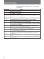
Meaning
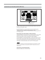
6
CTL display mode is selected. This bit setting is
available only when you set the RECORDER and
PLAYER TC/RTC/CTL selectors to CTL or RTC.
ON: The time data is displayed
between 00:00:00:00 and 23:59:59:24.
OFF: The time data is displayed
between –9:59:59:24 and +9:59:59:24.
5
The operation after the servo-mechanisms cannot
be locked is selected.
ON: Even though the unit failed to servo-lock, it
begins editing.
OFF: The unit does not begin editing until the
servo-mechanisms are locked.
4
The operation after the unit fails in synchronizing
the recorder with the player is selected. When
you set the SYNCHRO selector to ON or ON/CF,
this setting is available.
ON: The unit will synchronize again with the
accuracy of no frame slipping. When it finally
cannot, the unit does not begin editing.
OFF: Even if the recorder is not synchronized
with the player, the editing begins.
3
Synchronization begins depending on the player’s
or recorder’s operation.
ON: Player (The time base corrector must be
installed in the player.)
OFF: Recorder
2, 1, 0
These bits determine the edit timing during editing
between –1 and –7 frames. (0: OFF 1: ON)
000: The edit timing is automatically detected.
When the error whose number is 11 occurred,
select another one.
001: –1 frames
010: -2 frames
011: –3 frames
100: –4 frames
101: –5 frames
110: –6 frames
111: –7 frames
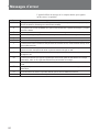
Meaning
7
4
Signal standard is set.
ON: PAL or SECAM system VTR
OFF: NTSC or PAL-M system VTR
ON
OFF
5
7
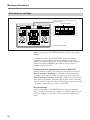
Left side
7
6
OFF
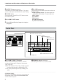
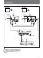
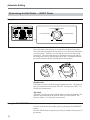
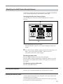
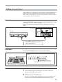
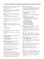
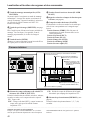
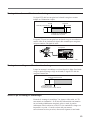
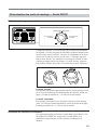
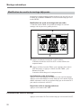
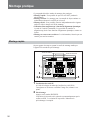
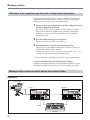
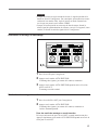
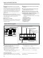
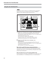
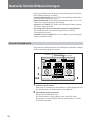
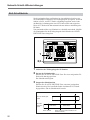
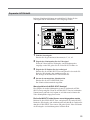
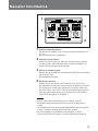
4 RECORDER TC/RTC/CTL selector
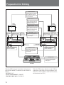
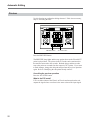
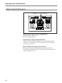
5 SYSTEM PRESET DIP switches
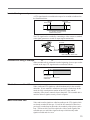
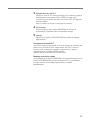
The default settings are all OFF (0) except for bit 7 of
the right DIP switches as illustrated. For the U.S.A.
model, bit 7 is set to OFF, and for the European model,
bit 7 is set to ON.
7
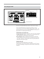
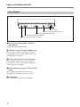
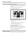
6 LEARN button
Press the button to detect the pinch on delay time of
the connected VTRs after turning on the unit.
a) When bit 7 of the left DIP switches is set to ON, 10 sec.
is selected as the CUE OUT start position.
9