1
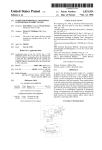
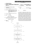
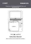
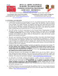
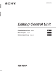
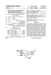
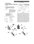
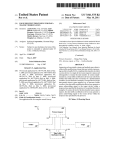
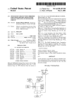
United States Patent [19]
4,430,652
[11]
[45]
Rothenbuhler et al.
[54] REMOTE CONTROL SYSTEM
[56]
Feb. 7, 1984
References Cited
U.S. PATENT DOCUMENTS
[75]
Invent0r8= Dan _E- Rothenbuhler, Acme; Galen
A-B1ery,Jr-, Belllngham, both of
4,038,590 7/1977 Knowlton .................... .. 340/825.69
4,178,549 12/1979 Ledenbach et al.
340/825.69
Wash.
4,197,525
4/1980 Biery et al. ................... .. 340/825.65
Primary Examiner-—Donnie L. Crosland
[73] Assignee:
Rothenbuhler Engineering Co.,
Attorney, Agent, or Firm——Christensen, O’Connor,
Sedro-Woolley, Wash.
Johnson & Kindness
[57]
ABSTRACT
A remote control system capable of utilizing manually
encoded signals is disclosed. The system is particularly
[21] APPI- N04 325,016
.
_
suitable for use in the logging industry because it is
[22] Flled'
Nov' 25’ 1981
capable of utilizing standardized whistle signals for both
remove control and audible signalling purposes. The
[51]
Int. Cl.3 ............................................ .. G08C 19/00
System includes a transmitter for transmitting a manu
[52]
U.S. Cl. ........................ .. IMO/825.69; 340/825.72;
ally encoded signal. The control signal is received by a
340/825.57; 340/82564; 340/870_21;
receiver and is decoded by a decoder that reduces the
34()/870.24; 375/23; 375/95; 212/160
manually encoded signal to a digitized signal. The digi
[5 8]
Field of Search .................... .. 340/ 825.69, 825.72,
tiled signal is compared with a set of reference digitized
340/ 825.6, 825.63, 825.64, 825.65, 825.57,
825.58, 82575, 539, 870,19, 870,24, 870,23,
signals, and if a match is found, a corresponding output
control signal is applied to a controlled device such as a
870.21, 870.2, 870.22; 375/23, 22, 25, 69, 75, 95,
96, 94; 370/8-9; 455/38, 70, 603; 212/160;
214/DIG. 2
//z
5/6/4444
WWW
/0
/
v
W/VIII/f/Z?
‘
‘V
yarder.
'
20 Claims, 11 Drawing Figures
A;
f
[Eff/V56
a 20
/
Z4
Z0
f
A,1 MTV/$4M
02700512 ‘ X 95W! 9
Adi/£2!
26
f/i/t/lll/t/é w/o/
?éV/[E
j
22
‘v (m[1!p
MM;
/
2‘
US. Patent
Feb. 7, 1984
257/12” 70 b’fé/A/ Ma 54)
Sheet 5 of7
4,430,652
1
4,430,652
2
of a remote control system having a coding scheme
REMOTE CONTROL SYSTEM
based on manually generated whistle signals.
Accordingly, it is an object and purpose of the pres
ent invention to provide an apparatus for utilizing man
The present invention is generally related to remote 5 ually encoded signals in a remote control system. More
speci?cally, it is an object of the invention to provide an
control systems and, more particularly, to remote con
FIELD OF‘THE INVENTION
trol systems that utilize manually encoded signals which
are decoded to provide corresponding output control
apparatus for utilizing manually encoded whistle signals
in a remote control system for use in the logging indus
signals and to execute predetermined control functions.
try.
It is also an object to achieve the foregoing objects in
BACKGROUND OF THE INVENTION
The logging industry is one area in which the use of
a remote control system wherein signals are manually
manually encoded signals has evolved extensively.
Such signals are known in the trade as whistle signals
and are employed as a means of communication be
tween workers in the ?eld. As the name implies, the
encoded according to a predetermined coding scheme,
and wherein such signals are decoded to execute prede
termined control functions.
It is another object of the invention to provide a
remote control system wherein manually encoded sig
signals consist of predetermined sequences of long and
nals are decoded to execute predetermined control
short whistle blasts produced by a whistle, horn, or
other audible signalling device. Typically, the audible
are also utilized to produce audible signals that repre
signalling device is remotely actuated by radio-fre
quency (RF) signals from a manually actuated transmit
ter held by a worker. Each signal represents a speci?c
instruction from one worker to another and usually
pertains to the operation of a speci?c type of machin
ery. For example, standardized whistle signals are used
to indicate a desired operation of yarding lines and
associated yarders used in yarding operations.
In addition to communicating instructions from one
worker to another, whistle signals serve an important
safety function in alerting other workers in the vicinity
of immediately impending changes in the operation of
the machinery. In this regard, workers in the logging
industry are cognizant of the standardized whistle sig
nals and rely on such signals for forewarning of changes
in the operation of the machinery. In recognition of this
safety aspect of the use of whistle signals, various states
and regulatory agencies have promulgated laws and
regulations mandating the use of standardized whistle
signals in logging operations.
In recent years the advantages of remote control
functions, and wherein the manually encoded signals
sent and serve to announce the control functions being
executed.
These and other objects will be apparent on consider
ation of the ensuing description of the invention and the
accompanying drawings.
SUMMARY OF THE INVENTION
In accordance with the present invention, a remote
control system includes a transmitting means for trans
~mitting a manually encoded signal consisting of a se
quence of pulses and interpulse spaces, a receiving
means for receiving the signal, and a decoding means
for decoding the received signal and applying a corre
sponding output control signal to a controlled device.
The decoding means includes ?rst means for measuring
the durations of the pulses as well as the durations of the
interpulse spaces. The decoding means further includes
second means for digitizing the pulse and space dura
tions by comparing the durations of successive pulses
and discriminating between long and short pulses and
by likewise comparing the durations of successive
spaces and discriminating between long and short
spaces, to thereby produce a digital representation of
the manually encoded signal. Finally, the decoding
systems, usually radio control systems, have become
apparent in the logging industry. The advent of such
systems has been complicated, however, by the neces
means includes a third means for correlating the digital
sity of adhering to the use of manually generated, stan 45 representation with a plurality of reference digital rep
dardized whistle signals for indicating the desired oper
resentations each corresponding to one of a plurality of
ations of logging machinery. Although there are vari
predetermined output control signals and for selecting
ous well known types of remote control systems that
could be adapted to provide remote control of logging
equipment, there has not been previously available a
one of the output control signals upon determination of
a match between the digital representation and one of
the reference digital representations, and fourth means
remote control system having a coding scheme based on
standard whistle signals. In large part this is due to the
fact that the whistle signals are manually generated and
controlled device.
In a preferred embodiment of the invention, the ?rst
are thus subject to some variation from one worker to
means, second means and third means are incorporated
for supplying the selected output control signal to the
another, as well as variation in a given signal when 55 in a digital computer that executes the timing, digitizing
produced at different times by an individual worker.
and correlating functions in accordance with a prede
For example, there may be signi?cant variation in dura
termined computer program. In such an embodiment,
tion of the individual whistle blasts making up the sig
the digital representation includes one or more digital
nal, as well as variation in the durations of the interven
words and each reference digital representation in
ing pauses, or spaces, between whistle blasts. Also, 60 cludes one or more corresponding reference digital
there may be a signi?cant variation in the relative .
words. If a match is found between the word or words
lengths of long and short whistle blasts, as well as varia
in the digital representation and the word or words in a
reference digital representation, the decoding means
tions in the relative durations of the intervening long
selects the corresponding output control signal and
and short spaces. Although such variation does not
ordinarily pose any problem with respect to communi 65 supplies that signal to the controlled device.
In accordance with another aspect of the invention,
cation and understanding between workers in the ?eld,
who compensate for such variation as a matter of
pulses are determined to be either long or short by
course, it has heretofore prevented the implementation
comparing the duration of each pulse with the average
4,430,652
3
duration of the longest and shortest pulses, and spaces
are likewise determined to be either long or short by
comparing the duration of each space with the average
duration of the longest and shortest spaces.
In another aspect of the invention, all of the pulses are
?rst compared to determine if the duration of the lon
gest pulse is greater than the'duration of the shortest
4,197,525, issued Apr. 8, 1980, to Biery et al., both of
which are assigned to the assignee of the present inven
tion and both of which are hereby incorporated by
reference.
,
The audible signalling device 16 produces an audible
“whistle” signal that corresponds to the manually en
coded signal. Ordinarily, the receiver 14 and the de
coder 18, and possibly also the signalling device 16, are
pulse by more than a predetermined amount, for exam
ple, by a factor of two. If the longest pulse is not greater
than the shortest pulse by more than such an amount, it
is assumed that all pulses are short pulses and the system
incorporated in a single receiving unit, although they
decodes the signal accordingly. If the longest pulse is
longer than the shortest pulse by more than the prede
termined amount, then the longest and shortest pulse
are illustrated separately for the purpose of this descrip
tion. The decoder 18 decodes the received, manually
encoded signal and applies a predetermined output con
durations are averaged and the pulses are evaluated as
being either long or short, as noted above. This proce
dure effectively takes into account the substantial differ
ence in average pulse lengths commonly observed in
manually encoded signals consisting of a sequence of
like pulses.
4
as disclosed in US. Pat. No. Re. 27,044, reissued Feb. 2,
1971 to Rothenbuhler et al. and in US. Pat. No.
trol signal 20 to a controlled device 22 through an inter
face device 24. Controlled device 22 may consist of any
one of various types of machinery that may be advanta
geously remoted controlled, for example, a yarding line
assembly. In FIG. 1, the output control signal 20 is
20 represented by a wide arrow to indicate that there are
These and other aspects and advantages of the inven
multiple connections between the decoder 18 and the
controlled device 22 through the interface device 24,
with the decoder 18 actuating various functions of the
tion will become more apparent on consideration of the
following detailed description of a preferred embodi
ment and the accompanying ?gures.
BRIEF DESCRIPTION OF THE DRAWINGS
FIG. 1 is a schematic block diagram of a preferred
embodiment of the remote control system of the present
controlled device 22 depending on the particular en
25 coded signal received. A second wide arrow 26 repre
sents a set of feedback connections between the con
trolled device 22 and the decoder 18 through the inter
face device 24, which feedback connections provide
signals to the decoder that positively indicate the states
of the various functions under remote control.
The signalling switch 12 may be a simple spring
invention including a decoder;
FIG. 2 is a schematic illustration of an exemplary
manually encoded signal;
FIG. 3 is a block diagram of the decoder;
FIG. 4 is a simpli?ed flow chart illustrating the se
biased ON/OFF switch that is selectively opened and
closed so as to cause the transmitter 10 to produce a
quential operation of the remote control system while
manually encoded signal such as that represented sche
under computer program control;
35 matically in FIG. 2. Such a signal consists of a sequence
FIGS. 5A-5B are a more detailed ?ow chart of the
of pulses 30 that are separated by intervening spaces 32.
operation of the decoder under main program control;
For a time corresponding to the duration of each pulse,
FIGS. 6A-6B are a ?ow chart illustrating the opera
tion of the decoder while under control of a REDUCE
resenting the duration of successive pulses and spaces in
the audible signalling device 16 is actuated to produce a
whistle blast, and for a time corresponding to the dura
tion of each space, the audible signalling device 16 is
deactuated and therefore silent. The durations of both
the pulses 30 and spaces 32 are variable. In accordance
with the standard system of whistle signals used in the
the manually encoded signal;
logging industry, the pulses 30 are either short or long
subroutine;
FIG. 7 is a schematic representation of memory loca
tions in the decoder used for storage of count data rep
FIG. 8 is a schematic representation of REF 1 and 45 in duration, and the spaces 32 are likewise either short
REF 2 memory locations in the decoder and a NUM
or long. The long spaces correspond generally to pauses
BER register in the decoder which contain a digital
between groups of pulses, whereas the short spaces
representation of the manually encoded signal in FIG.
generally correspond to the spacing between pulses in
each pulse group. Termination of the whistle signal is
FIG. 9 is a schematic representation of a table in 50 signi?ed by an excessively long space 33 (whose dura
memory in the decoder which contains a plurality of
tion is greater than that of any of the interpulse spaces
reference digital representations'each corresponding to
32) following any of pulses 30.
2; and,
'
a predetermined output control signal from the remote
control system.
DETAILED DESCRIPTION OF THE
PREFERRED EMBODIMENT
Referring to FIG. 1, a preferred embodiment of the
remote control system includes a transmitter 10 that is
The durations of both the pulses 30 and the spaces 32
are ordinarily somewhat variable due to the fact that
55
actuated by a signalling switch 12 so as to emit a manu 60
ally encoded signal 13 modulated in an appropriate
they are manually generated and thus subject to human
variation in their timing. The decoding of such a signal,
notwithstanding the variability in pulse and space dura
tions, is accomplished by the decoder in a manner de
scribed more fully below.
In the preferred embodiment, the decoder 18 includes
a suitably programmed digital computer such as the
manner on a RF carrier. Signal 13 is received by a
eight-bit, single-chip microcomputer sold by Intel Cor
receiver 14 that demodulates the manually encoded
signal and applies it to both an audible signalling device
poration of Santa Clara, Calif. and identi?ed by the
Model No. 8748. Details regarding the operation and
16 and to a decoder 18. Preferably, the transmitter and
tion and demodulation of the manually encoded signal
programming of the 8748 microcomputer are set forth
in a user’s manual published by Intel Corporation in
1978 under the title “MCS-48 Microcomputer User’s
by means of a scheme known as “two-tone sequential”
Manual”. With reference now to FIG. 3, the decoder of
the receiver are constructed so as to provide modula
5
4,430,652
6
crocomputer that consist of a clock, a CPU, a program
memory, a data memory, a timer/event counter, and a
that corresponds to an unacceptably long whistle blast
duration, ordinarily approximately one second. If the
count is too large, then it is determined that the pulse is
plurality of I/O ports. The clock provides appropriate
too long and represents an aberrant signal and a return
the preferred embodiment includes a single-chip mi
is made to the start of the main program. If the count in
clock signals to the CPU, and the CPU, the program
the COUNTER register is not too large and the pulse is
memory, the data memory, the timer/event counter,
and the I/O ports are interconnected by appropriate
still present (as detected in step 107), the microcom
puter returns to the DELAY subroutine and continues
data and address buses and appropriate control lines. A
incrementing the count in the COUNTER register at
set of program instructions required for the operation of
the decoder is stored in the program memory (and de 10 2.5 millisecond intervals.
Upon termination of the pulse as detected in step 107,
cribed hereinafter with reference to FIGS. 4, 5A, 5B,
a determination is made in step 108 as to whether the
6A and 6B) and all data storage and computations are
carried out in the data memory (with a portion of the
data memory being described hereinafter with refer
ence to FIGS. 7, 8 and 9). The manually encoded signal
count in the COUNTER register is too small. If the
count is too small, for example, less than a predeter
through the I/O ports, as are the signals on feedback
mined minimum count corresponding to approximately
50 milliseconds, the pulse is ignored and the microcom
puter returns to step 103 wherein the COUNTER regis
connections 26 from the controlled device 22 through
ter is reset to zero. This step of the program effectively
from receiver 14 is provided to the microcomputer
interface device 24. The I/O ports are also connected to
prevents spurious momentary pulses from being consid
a plurality of control relays 34 by interconnections 36,
ered as valid pulses.
Upon termination of the ?rst pulse and after af?rma
tive determination that the duration of the pulse as de
termined by the count in the COUNTER register is
put control signal 20 (in the form of relay contact clo
neither too long nor too short, the count in the
sures) to the controlled device 22 through interface
25 COUNTER register (step 109) is stored in a memory
device 24.
and the signals on interconnections 36 cause control
relays 34 to assume various states so as to provide out
FIG. 4 is a simpli?ed flow chart illustrating the oper
ation of the decoder 18 under program control. Upon
start-up of the decoder, the microcomputer places all
location indicated by the current value of the
POINTER register, which in the ?rst instance is a ?rst
memory location set aside for recording of count data.
-A schematic representation of how the memory loca
control relays 34 in a desired initial state. The mi
crocomputer then waits for a signal from receiver 14. 30 tions for count data are con?gured and sequentially
loaded is shown in FIG. 7.
Upon receipt of a signal, the durations of the pulses 30
The POINTER and NUMBER registers are also
and the intervening spaces 32 are successively mea‘
incremented in step 109. In the ?rst instance, the
sured. Upon detection of the end of a whistle signal, the
POINTER register thus will point to a second memory
measured durations of the pulses and spaces are digi
tized into short and long pulses and spaces, and corre 35 location for count data and the NUMBER register thus
sponding digital words are assembled. The digital
words are compared with entries in a look-up table in
the data memory until a match is found. Upon ?nding a
match, the microcomputer executes corresponding in
will contain a count of one. In the next step 110, a deter
mination is made as to whether the count in the NUM
BER vregister is too large by comparing the count with
a predetermined maximum count. As can be appreci
structions on the basis of an address located in the look 40 ated, the count in the NUMBER register represents the
up table by causing control relays 34 to assume those
number of pulses thus far received in the whistle signal.
states representing the output control signal required
for the Whistle signal.
If the maximum number of whistle blasts in any stan
dardized whistle signal is eight, the predetermined max
imum count is eight.
A more detailed flow chart is set forth in FIGS.
Provided the count in the NUMBER register is not
5A-5B and 6A-6B. Brie?y, FIGS. 5A-5B illustrate the 45
too large, the COUNTER register is reset to zero in
operation of the decoder under main program control,
step 111, and the duration of the ensuing space is mea
whereas FIGS. 6A-6B illustrate the operation of the
sured in steps 112, 113 and 114. In this regard, the
decoder under control of a major subroutine entitled
REDUCE. Referring to FIG. 5A, upon start-up of the
DELAY subroutine is again implemented in step 112.
decoder a STOP signal is generated in step 101 so as to
cause each of the control relays 34 to be placed in a
desired initial state. The microcomputer then enters a
As with the pulses, there is a limit set on the maximum
In the next step 104, the presence or absence of an en
large and a pulse is absent, the microcomputer contin
coded signal is detected, as indicated by receipt of a
pulse from the receiver 14. If a pulse is detected, the
ues to pass through the DELAY subroutine to incre
ment the count in the COUNTER register at 2.5 milli
microcomputer enters a subroutine denoted DELAY
second intervals. Upon the detection of a pulse in step
(step 105), in which the count in the COUNTER regis
114, a determination is made in step 115 so as to whether
permissible duration of a valid space, for example, one
second. If the count in the COUNTER register exceeds
a predetermined maximum count corresponding to this
routine identi?ed as BEGIN. In step 102, a register
maximum permissible duration, a determination is made
dedicated for use as a pointer, which is hereinafter re
ferred to as the POINTER register, is set to a predeter 55 in step 113 that the whistle signal has ended and the
microcomputer proceeds directly to the routines shown
mined initial value. Also, a second dedicated register,
in FIG. 5B. If the count is not too large, a determination
referred to hereinafter as the NUMBER register, is
is made in step 114 as to whether a pulse is present. As
reset to zero. In the next step 103, a register referred to
long as the count in the COUNTER register is not too
hereinafter as the COUNTER register is reset to zero.
ter is incremented by one after the elapse of 2.5 millisec 65 the count in the COUNTER register is too small. This
determination effectively prevents the registering of
onds. After each increment, a determination is made in
spurious momentary gaps in a pulse as valid spaces. If
step 106 as to whether the count in the COUNTER
such a spurious gap (usually less than 50 milliseconds) is
register is greater than a predetermined maximum count
7
4,430,652
detected, i.e., if the countin the COUNTER register is
less than a predetermined minimum count correspond
ing to the spurious gap, the POINTER register is decre
mented (step 117) and the count in the thus-pointed
8
the determination in step 122 will always be negative
since there always will be at least one pulse in each
whistle signal. Then, an accumulator is reset to zero
the previous pulse) is stored in the COUNTER register.
(step 123) and an LRG routine is entered in which the
duration of the longest pulse is determined. This is done
by sequentially comparing the pulse counts stored in the
The function of this step in the program is to restart the
memory locations with the current count in the accu
timing of the previous pulse at the previous count there
for as the microcomputer returns to step 105.
Assuming that the count in the COUNTER register
is not too small, i.e., that a valid interpulse space has
been detected and timed, the count in the COUNTER
register is stored (step 116) at the memory location
indicated by the POINTER register, which for the ?rst
than the count in the accumulator, the determination in
step 124 is negative so that the memory address in the
POINTER register is stored in a register identi?ed as
R1 (step 125). Then the pulse count from the memory
memory location for count data (which is the count for
space is the second memory location for count data.
The POINTER register is then incremented and the
microcomputer returns to step 103 to begin timing the
next pulse. It will be seen from the discussion thus far
that as the microcomputer continues to loop through
that portion of the BEGIN routine starting at step 103,
the durations of successive pulses and interpulse spaces
mulator. More speci?cally, if a pulse count is not less
location pointed to by the pointer (i.e., pointed to by the
address in R1) is placed in the accumulator (step 126). If
a pulse count is less than the count in the accumulator,
the determination in step 124 is af?rmative so that the
microcomputer skips step 125 and proceeds directly to
step 126. The POINTER register is then incremented
by two (step 127) so as to skip the next memory location
and to point to the memory location containing the
count of the next pulse. Also, the count in the
are measured and the corresponding counts are stored
COUNTER register is decremented by one. A determi
in successive memory locations for count data. At the
nation is then made in step 128 as to whether the count
same time, the count in the NUMBER register indicates
in the COUNTER register is zero. If not, the mi
the total number of pulses received.
25
crocomputer returns to step 124 and compares the next
Upon determining that a complete whistle signal has
pulse count with the count in the accumulator. The
been received, by detecting an excessive number of
pulses in step 110 or by detecting an excessively long
space in step 113, the microcomputer enters a routine
identi?ed as TERMINATE (FIG. 5B), during the ?rst
step of which (118) registers identi?ed as REF 1 and
REF 2 are reset to zero, and a FLAG bit is reset to zero.
The microcomputer then enters (step 110) a subroutine
identi?ed as REDUCE, set forth in FIGS. 6A and 6B,
in which the durations of the pulses and spaces in the
whistle signal are reduced to ?rst and second digital
words, respectively, representing the sequence of long
microcomputer thereafter continues to loop through
that portion of the LRG routine including steps 124,
125, 126, 127 and 128 until all pulse counts have been
compared and the count in the COUNTER register is
zero. At this time, the count in the accumulator is stored
in a register denoted R4 (step 129). RegisterR4 thus
contains a count corresponding to the duration of the
longest pulse in the whistle signal.
The microcomputer then reinitializes the
COUNTER and POINTER registers in steps 130 and
131. As before, the count in the COUNTER register is
and short pulses and the sequence of long and short
spaces in the whistle signal.
Referring to FIG. 6A, during the ?rst step 120 of the
set to the count in the NUMBER register less the
FLAG bit, which in the ?rst pass is equal to zero. Like
microcomputer through the REDUCE subroutine, the
the accumulator, the microcomputer proceeds in step
count in the COUNTER register is equal to the number
of pulses in the whistle signal since the FLAG bit was
register in register R1. In the ?rst instance, register R1
reset in step 118 (FIG. 5B).
The POINTER register is initialized (step 121) at a
beginning value corresponding to the address of the
will therefore contain the memory address for the ?rst
memory location. In the next step 135 the count in the
?rst memory location is loaded into the accumulator. In
wise, the POINTER register is set to its beginning value
REDUCE subroutine the count in the COUNTER
plus the value of the ?ag bit. Thus, in the ?rst pass the
register is set to the count in the NUMBER register less
POINTER register again points to the ?rst memory
the value of the FLAG bit. As will be seen from the
location. In the next step 132 the accumulator is set to
discussion below, the count in the COUNTER register
in the REDUCE subroutine is equal to the number of 45 its maximum count.
Thereafter, the microcomputer enters a SML routine
pulses in the signal when the pulse durations are being
in which the duration of the shortest pulse is deter
reduced, and is equal to the number of spaces when the
mined. In step 133, the count in the memory location
space durations are being reduced. The FLAG bit can
pointed to by the POINTER register, which corre
be conveniently used to set the count in the COUNTER
sponds in the ?rst instance to the duration of the ?rst
register for either pulses or spaces since the number of
pulse, is compared with the count in the accumulator. If
spaces in any whistle signal is always exactly one less
the count in the ?rst memory location is less than that in
than the number of pulses. Upon the ?rst pass of the
?rst memory location for count data, plus the value of
the FLAG bit. In the ?rst pass of the microcomputer
through the REDUCE subroutine, the POINTER reg
ister points to the ?rst memory location which contains
the count corresponding to the duration of the ?rst
134 to store the memory address in the POINTER
the next step 136, the POINTER register is incremented
by two to point to the memory location for the next
pulse count, and the COUNTER register is decre
mented by one. A check is made in step 137 to deter
mine whether the count in the COUNTER register is
pulse.
zero. If not, additional pulse counts need to be com
In the next step 122 of the REDUCE subroutine, a 65 pared and the microcomputer continues to loop
through that portion of the SML routine that has been
determination is made as to whether the count in the
COUNTER register equals zero. Upon the ?rst pass of
described until all pulse counts have been compared and
the microcomputer through the REDUCE subroutine,
the count in the COUNTER register is zero. The count
4,430,652
representing the duration of the shortest pulse is then
10
position in step 143. In the event that the ?rst pulse is a
loaded into the accumulator in step 138.
At this time, the accumulator contains a count repre
long pulse, register R1 will therefore contain “10”, and
in the event that the ?rst pulse is a short pulse, register
R1 will therefore contain “00”. Also in step 148, the
POINTER register is incremented by two to point to
the memory location for the next pulse count and the
COUNTER ‘register is decremented by one. A determi
senting the duration of the shortest signal pulse and
register R4 contains a count representing the duration
of the longest pulse. These counts are compared in
' succeeding steps to determine whether the whistle sig
nal consists of both long and short whistle blasts, or
nation is then made in step 149 as to whether the count~
consists of a sequence of blasts which although they
in the COUNTER register is zero. If not, additional
may vary somewhat in duration, are intended to repre
pulse counts need to be classi?ed and the microcom
sent a sequence of blasts of uniform duration. In this
puter continues to loop through the ASMBL routine
regard, it is noted that it is sometimes dif?cult to deter
until all pulse counts have been classi?ed and the count
mine whether a sequence of whistle blasts of uniform
in the COUNTER register is zero. At this time, the
length is intended to represent a sequence of short blasts
count in register R1 comprises a pulse word that is
or a sequence of long blasts. However, in the logging 15 right-justi?ed and that represents the sequence of long
industry, there is no standardized whistle signal corre
and short pulses in the Whistle signal, with a one repre
sponding to a sequence of long whistle blasts, so that if
senting a long pulse and a zero representing a short
a sequence of uniform whistle blasts is detected it can
pulse. An exemplary pulse Word for the whistle signal
safely be assumed to represent a sequence of short whis
illustrated in FIG. 2 which consists of a long blast, a
tle blasts.
short blast, two long blasts, and a short blast is accord
In step 139, the count in the accumulator is multiplied
by two. A determination is then made in step 140 (FIG.
ingly “00010110”, assuming that register R1 is an eight
bit register. Thereafter, the microcomputer returns to
6B) as to whether the count in the accumulator is too
the main program.
large, i.e., as to whether the accumulator has over
When the microcomputer exits from the REDUCE
?owed. If so, it is determined that all pulses in the whis 25 subroutine in step 119 (FIG. 5B) and then proceeds to
tle signal are short so that the microcomputer resets
step 150, it should be noted that the pulse word in regis
register R1 to zero (step 140A) and returns to its main
ter RI contains either all zeroes (in the event that the
program.
whistle signal is invalid or in the event that all pulses in
If the count in the accumulator is not too large, the
-the whistle signal are short) or a sequence of ones and
count in the accumulator is then compared with the
zeroes (in the event that at least one pulse in the whistle
count in register R4 in step 141. If the count in the
signal is long). In step 150, the pulse word in register R1
accumulator is greater than that in register R4, then the
is stored in a memory location identi?ed as REF 1 (as
shortest pulse is more than half as long as the longest
shown in FIG. 8 for the whistle signal in FIG. 2) and
pulse. In this situation, it is assumed that there is not a
the FLAG bit is complemented (i.e., set to one). There
signi?cant difference between the durations of the whis 35 after, the microcomputer again proceeds in step 151 to
tle blasts and that the whistle signal accordingly consists
enter the REDUCE subroutine. During this second
of a sequence of short whistle blasts, so that the mi
pass through the REDUCE subroutine, the duration of
crocomputer returns to the main program after ?rst
the longest space is determined, the duration of the
resetting register R1 in step 140A.
shortest space is determined, and these durations (repre
If the count in the accumulator is not greater than the 40 sented respectively by counts in the accumulator and in
count in register R4, then it is assumed that there are
register R4) are compared to determine if there is a
signi?cant difference between these durations. If a sig
ni?cant difference is determined, then it is noted that
both long and short pulses in the whistle signal and in
the next step 142 the average of the longest pulse dura
tion (the count in register R4) and the shortest pulse
both interpulse spaces (short spaces) and pauses (long
duration (the count in the memory location whose 45 spaces) are present in the whistle signal. The average
memory address is in register R1) is determined. This
space duration is then determined and the space dura
average pulse duration (or count) is loaded into register
tions are classi?ed as either long or short by comparing
R4 and is used in the ensuing steps to discriminate be
them with the average space duration. Once having
tween long and short pulses.
classi?ed the space durations, a second digital or
In the next steps 143 and 144, the COUNTER and 50 “space” word is assembled in register R1 that represents
POINTER registers are again reinitialized, and in the
the sequence of long and short spaces in the whistle
next step 145, the register R1 is reset to zero. The mi
signal.
crocomputer then enters a routine identi?ed as ASMBL
wherein a ?rst or “pulse” digital word representing the
sequence of long and short pulses in the whistle signal is
assembled.
An inquiry is made in step 146 as to whether the
count in the memory location pointed to by the
POINTER register is greater or less than the count in
register R4, i.e., whether the ?rst pulse is a long or a
short pulse. If the determination in step 146 is affirma
tive, the count in register R1 is incremented by one in
55
Although the operation of the microcomputer when
passing through the REDUCE subroutine in step 151 is
similar to that previously described for step 119, the
following differences should be noted. First, the count
in the COUNTER register is set to the count in the
NUMBER register less the value of the FLAG bit in
step 120. Since the FLAG bit has now been set (in step
150) the count in the COUNTER register is therefore
equal to the number of spaces in the whistle signal. In
step 121, the POINTER register is initialized at a begin
ning value corresponding to the address of the first
memory location for count data, plus the value of the
step 147. If the determination in step 146 is negative, the
count in register R1 is unchanged. Therefore, if the ?rst
pulse is a long pulse, the rightmost location in register 65 FLAG bit. Since the FLAG bit has now been set, the
R1 contains a one, and if the ?rst pulse is a short pulse,
POINTER register points to the second memory loca
the rightmost location in register R1 contains a zero.
tion which contains the count corresponding to the
The count in register R1 is then shifted left by one
duration of the ?rst space (if any). If the whistle signal
11
4,430,652
contains a single pulse, the determination in step 122 is
affirmative (i.e., there are no spaces) whereby register
R1 is reset to zero in step 122A (so that the space word
therein includes all zeros) and the microcomputer there
after returns to its main program. Second, the count in
the accumulator (which is the count of the shortest
space) is multiplied by two in step 139. A determination
is then made in step 140 (FIG. 6B) as to whether the
count in the accumulator is too large. If so, it is deter
mined that all spaces in the whistle signal are short so
that the microcomputer resets register R1 to zero (step
140A) and returns to its main program. If the count in
the accumulator is not too large, the count in the accu
mulator is then compared with the count in register R4
(which is the count of the longest space) in step 141. If
the count in the accumulator is greater than that in
register R4, then the shortest space is more than half as
12
ing output signal is provided to control relays 34 and
thus to the controlled device and the performance of
the controlled device in providing the required control
actions is monitored by detecting the signals on feed
back connections 26. After execution of the instruction,
the microcomputer returns to the BEGIN routine
(FIG. 5A) and awaits another whistle signal.
If no match is found between the pulse word in REF
1 and the reference pulse word in the ?rst entry in the
table for an'output control signal, then the POINTER
register is incremented three times in steps 161, 162 and
163 to point to the first entry for the next output control
signal in the table and the count in register R4 is decre
mented. Likewise, if no match is found between either
the space word in REF 2 with the reference space word
in the second entry or the count in the NUMBER regis
ter with the reference number in the third entry, the
POINTER register is incremented an appropriate num
ber of times to point to the ?rst entry for the next output
long as the longest space. In this situation, it is assumed
that there is not a signi?cant difference between the
durations of the spaces and that the whistle signal ac 20 control signal in the table and the count in register R4 is
decremented.
cordingly consists of a sequence of short spaces so that
Each time the count in register R4 is decremented, a
the microcomputer returns to the main program after
determination is made (step 164) as to whether the
?rst resetting register R1 in step 140A.
count in register R4 is zero. If the determination in step
Upon exiting from its second pass through the RE
DUCE subroutine in step 151, the microcomputer then 25 164 is negative, the entire look-up table has not been
searched and the microcomputer continues to return to
(step 152) stores the space word in register R1 in a
and loop through that portion of the CORRELATE
memory location identi?ed as REF 2. For the whistle
subroutine starting at step 154 until a complete match is
signal illustrated in FIG. 2 in which there are two short
found. If no complete match is found after the entire
spaces, a long space, and a short space, the space word
accordingly stored in REF 2 is “00000010” as illustrated 30 look-up table has been searched, the determination in
step 164 is affirmative and the microcomputer returns to
in FIG. 8.
the BEGIN routine without providing any output con
When the microcomputer has stored the pulse and
trol signal.
space words in REF 1 and REF 2, respectively, the
It will be appreciated that the system just described
microcomputer enters a subroutine identi?ed as COR
RELATE in which the pulse and space words and the 35 effectively converts whistle signals generated by a
worker in the ?eld to output control signals that control
count in the NUMBER register are compared with
various functions of a remotely controlled device. The
corresponding reference words in a look-up table stored
system accommodates ordinary human variation in the
in the data memory. In the preferred embodiment, there
duration of the whistle blasts as well as the intervening
are four successive entries in the look-up table for each
output control signal (see FIG. 9). The ?rst and second 40 gaps between such blasts, yet nevertheless rejects whis
tle signals that are unreasonably inconsistent with whis
entries contain reference pulse and space words, the
tle signals as they are generally recognized in the ?eld.
third entry contains a reference number representing
For example, any whistle blast that is either too short or
the number of pulses in the reference pulse word in the
too long is rejected, as is any intervening gap that is
?rst entry, and the fourth entry contains an address in
the data memory at which will be found an instruction 45 either too short or too long. Nevertheless, the system is
capable of accommodating substantial variation be
which when executed causes the microcomputer to
supply the corresponding output control signal to the
control relays.
tween the lengths of short and long whistle blasts as
well as the lengths of short and long intervening spaces.
In step 153 of the CORRELATE subroutine, a count
is stored in register R4 corresponding to the number of
ence to a preferred embodiment, it will be understood
Although the present invention is described by refer
that various modi?cations, alterations and substitutions
output control signals in the look-up table. Also, the
can be made without departing from the spirit of the
POINTER register is loaded with the address of the
invention. Accordingly, the scope of the invention is
?rst entry in the look-up table (which will be the ad
defined by the following claims.
dress containing the ?rst reference pulseword). In the
The embodiments of the invention in which an exclu
next step 154-, the pulse word in REF 1 is compared 55
sive property or privilege is claimed are de?ned as
with the reference pulse word thus addressed. If there is
follows:
a match, the POINTER register is incremented (step
155) to the second entry and the space word in REF 2
is compared (step 155) with the reference space word
1. A remote control system comprising:
transmitting means for transmitting a manually en
thus addressed. If there is a match, the POINTER regis
ter is again incremented (step 157) and the count in the
coded signal consisting of a sequence of pulses and
NUMBER register is compared (step 158) with the
receiving means for receiving said manually encoded
reference number thus addressed. If there is a match,
the POINTER register is again incremented (step 159)
to the fourth entry which contains the address in the 65
data memory for the instruction for the corresponding
output control signal. That instruction is executed by
the microcomputer in step 160 wherein the correspond
interpulse spaces;
signal; and,
decoding means for decoding the manually encoded
signal received by said receiving means, said de
coding means including ?rst means for determining
the duration of each pulse and each interpulse
space, second means for digitizing the duration of
13
4,430,652
14
8. The remote control system de?ned in claim 7
wherein each said set of three reference digital words
further includes a fourth reference digital word repre
each pulse and each interpulse space so as to form
a digital representation of said manually encoded
signal, third means for correlating said digital rep
resentation with a plurality of reference digital
senting the corresponding output control signal and
representations each corresponding to one of a
wherein said third means is operative to select the cor
plurality of predetermined output control signals
responding output signal represented by said fourth
and for selecting one of said output control signals
upon determination of a match between said digital
representation and one of said plurality of refer
ence digital representations, and, fourth means for
supplying said selected output control signal to a
controlled device.
reference digital word in a set upon determination of a
complete match between said three digital words and
the three reference digital words in that set.
9. The remote control system de?ned in claim 1
wherein said manually encoded signal is a whistle signal
used in the logging industry and wherein said plurality
of reference digital representations consist of standard
ized whistle signals used in the logging industry.
2. The remote control system de?ned in claim 1
wherein said second means classi?es said pulses and said
10. The remote control system de?ned in claim 9
wherein said transmitting means transmits said whistle
signal by modulating said whistle signal on a RF carrier
and wherein said receiving means receives said whistle
spaces into long and short pulses and long and short
spaces and forms said digital representation as consist
ing of a digital sequence representing the sequence of
long and short pulses in said manually encoded signal
and a digital sequence representing the sequence of long
and short spaces in said manually encoded signal.
3. The remote control system de?ned in claim 2
signal by demodulating said whistle signal from said RF
wherein said second means determines the durations of
the longest and shortest pulses in said manually encoded
signal and determines the average pulse duration
wherein said system further comprises audible signal
ling means for providing an audible signal correspond
ing to the whistle signal received by said receiving
thereof, and wherein said second means classi?es said
means.
pulses into long and short pulses by comparing the
12. The remote control system de?ned in claim 1
wherein said ?rst means, said second means and said
carrier.
11. The remote control system defined in claim 9
duration of each pulse with said average pulse duration.
‘third means are incorporated in a digital computer and
4. The remote control system defined in claims 2 or 3
wherein said second means determines the durations of
the longest and shortest spaces in said manually en
wherein their respective timing, digitizing and correlat
ing functions are executed by said computer under pro
gram control.
coded signal and determines the average space duration
thereof, and wherein said second means classi?es said
13. A decoding means for decoding a manually en
coded signal consisting of a sequence of pulses and
interpulse spaces, said decoding means including ?rst
means for determining the duration of each pulse and
each interpulse space, second means for digitizing the
spaces into long and short spaces by comparing the
duration of each space with said average space dura
tion.
5. The remote control system de?ned in claim 3
durations of each pulse and each interpulse space so as
to form a digital representation of said manually en
wherein said second means further determines whether
the duration of the longest pulse is greater than the
duration of the shortest pulse by more than a predeter
mined amount and classi?es said pulses as being of uni
coded signal, and third means for correlating said digital
representation with a plurality of reference digital rep
form duration in the event that the duration of the lon
resentations each corresponding to one of a plurality of
gest pulse is not greater than the duration of the shortest
predetermined decoder output signals and for selecting
one of said decoder output signals upon determination
6. The remote control system de?ned in claim 2 45 of a match between said digital representation and one
of said plurality of reference digital representations.
wherein said digital representation includes a set of
14. The decoding means de?ned in claim 13 wherein
three digital words, a ?rst one of said digital words
said second means classi?es said pulses and said spaces
consisting of a sequence of bits representing the se
into long and short pulses and long and short spaces and
quence of long and short pulses in said manually en
forms said digital representation as consisting of a digi
coded signal, a second one of said digital words consist
tal sequence representing the sequence of long and short
ing of a sequence of bits representing the sequence of
pulse by said predetermined amount.
pulses in said manually encoded signal and a digital
sequence representing the sequence of long and short
spaces in said manually encoded signal.
long and short spaces in said manually encoded signal,
and a third one of said digital words representing the
number of pulses in said manually encoded signal.
7. The remote control system de?ned in claim 6 55
wherein each of said plurality of reference digital repre
sentations includes a set of three reference digital
words, a ?rst one of said reference digital words con
sisting of a sequence of bits representing a sequence of
long and short pulses, a second one of said reference 60
digital words consisting of a sequence of bits represent
ing a sequence of long and short spaces, and a third one
of said reference digital words representing a number of
pulses, and wherein said third means successively com
15. The decoding means de?ned in claim 14 wherein
said second means determines the durations of the lon
gest and shortest pulses in said manually encoded signal
and determines the average pulse duration thereof, and
wherein said second means classi?es said pulses into
long and short pulses by comparing the duration of each
pulse with said average pulse duration.
16. The decoding means de?ned in claims 14 or 15
wherein said second means determines the duration of
the longest and shortest spaces in said manually en
pares said digital representation with said plurality of
reference digital representations until a complete match
65 coded signal and determines the average space duration
is found between said set of three digital words and a set
spaces into long and short spaces by comparing the
of three reference digital words.
duration of each space with average space duration.
thereof, and wherein said second means classi?es said
15
4,430,652
16
17. The decoding means de?ned in claim 14 wherein
19. The decoding means de?ned in claim 18 wherein
said second means further determines whether the dura
each of said plurality of reference digital representa
tion of the longest pulse is greater than the duration of
tions includes a set of three reference digital words, a
?rst one of said reference digital words consisting of a
sequence of bits representing a sequence of long and
short pulses, a second one of said reference digital
the shortest pulse by more than a predetermined
amount and classi?es said pulses as being of uniform
duration in the event that the duration of the longest
pulse is not greater than the duration of the shortest
words consisting of a sequence of bits representing a
sequence of long and short spaces, and a third one of
pulse by said predetermined amount.
said reference digital words representing a number of
18. The decoding means de?ned in claim 14 wherein
said digital representation includes a set of three digital
words, a ?rst one of said digital words consisting of a
pulses, and wherein said third means successively com
sequence of bits representing the sequence of long and
short pulses in said manually encoded signal, a second
is found between said set of three digital words and a set
pares said digital representation with said plurality of
reference digital representations until a complete match
of three reference digital words.
20. The decoding means de?ned in claim 13 wherein
one of said digital words consisting of a sequence of bits
said manually encoded signal is a whistle signal used in
the logging industry and wherein said plurality of refer
ence digital representations consist of standardized
representing the sequence of long and short pulses in
said manually encoded signal, and a third one of said
digital words representing the number of pulses in said
manually encoded signal.
whistle signals used in the logging industry.
20
25
30
35
45
50
55
65
*
‘4K
*
*
*