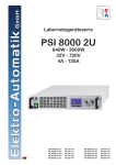
1
Bedienungsanleitung
Instruction Manual
EA-PSI 800 R
Abb. ähnlich / Figure similar to actual product
1000W / 1500W
PSI 880-40R :
PSI 880-60R :
PSI 8360-10R :
PSI 8360-15R :
21 540 407
21 540 408
21 540 409
21 540 410
DE
Impressum
Elektro-Automatik GmbH & Co. KG
Helmholtzstrasse 31-33
41747 Viersen
Germany
Telefon: 02162 / 37850
Fax: 02162 / 16230
Web: www.elektroautomatik.de
Mail: [email protected]
© Elektro-Automatik
Nachdruck, Vervielfältigung oder auszugsweise,
zweckentfremdete Verwendung dieser Bedienungsanleitung sind verboten und können bei Nichtbeachtung rechtliche Schritte nach sich ziehen.
Sicherheitshinweise
• Der Querschnitt der Lastanschlußkabel muß für
den maximalen Ausgangsstrom des jeweiligen
Gerätes ausgelegt sein!
• Der Netzanschluss darf nur von entsprechendem
Fachpersonal ausgeführt werden!
• Es ist sicherzustellen, daß keine Gegenstände in
die Lüftungsöffnungen gelangen!
• Die Lufteinlässe und Luftaustritte sind immer frei
und sauber zu halten!
• Um eine ausreichende Kühlung zu gewährleisten
ist auf die korrekte Einbaurichtung und auf die
Einhaltung eines ausreichenden Abstandes zu
anderen Teilen zu achten!
• Das Gerät ist vor direkter Sonneneinstrahlung und
Feuchtigkeit zu schützen!
• Das Abdeckblech des Schnittstelleneinschubs ist
bei nicht bestückter Schnittstellenkarte unbedingt
zu montieren, um ein Hineingreifen in das Gerät
zu verhindern!
Bedienungsanleitung
PSI 800 R Serie
Stand: 11.05.2015
3
DE
Inhaltsverzeichnis
Seite
1.Allgemeines........................................................................................................................................... 5
1.1Einleitung........................................................................................................................................ 5
1.2Sichtprüfung................................................................................................................................... 5
1.3Lieferumfang................................................................................................................................... 5
2.Installation.............................................................................................................................................. 5
2.1Montage.......................................................................................................................................... 5
2.2Netzanschluß.................................................................................................................................. 5
2.3 Anschluß DC-Ausgang und Fernfühlung........................................................................................ 5
2.4 Anschluß Analoge Schnittstelle...................................................................................................... 6
3.Funktionsbeschreibung.......................................................................................................................... 6
3.1Allgemein........................................................................................................................................ 6
3.2 Fernfühlung (Remote sense) ......................................................................................................... 6
3.3 Überspannungsschutz (OVP) ........................................................................................................ 6
3.4 Wiedereinschaltung nach Netzausfall............................................................................................ 6
3.5 Übertemperaturabschaltung (OT)................................................................................................... 6
3.6Unterspannungsüberwachung........................................................................................................ 7
3.7 Konfigurierbare Spannungsprofile.................................................................................................. 7
3.8Bedienorte...................................................................................................................................... 7
3.9 Technische Daten........................................................................................................................... 8
3.10 Mechanische Zeichnungen............................................................................................................. 9
4.Bedienung.............................................................................................................................................11
4.1 Bedien- und Anzeigeeinheit...........................................................................................................11
4.2 Spannungsprofil auswählen..........................................................................................................11
4.3 Spannungsprofil anpassen........................................................................................................... 12
4.4 Stromsollwert einstellen................................................................................................................ 12
4.5 Direktes Einstellen der Sollspannung........................................................................................... 12
4.6 Das Menü..................................................................................................................................... 12
4.7Alarme ......................................................................................................................................... 14
5.Fernsteuerung...................................................................................................................................... 14
5.1 Über digitale Schnittstelle............................................................................................................. 14
5.2 Über analoge Schnittstelle............................................................................................................ 14
6. Weitere Anwendungen......................................................................................................................... 16
6.1Reihenschaltung........................................................................................................................... 16
6.2Parallelschaltung.......................................................................................................................... 16
7.Sonstiges............................................................................................................................................. 17
7.1 Zubehör und Optionen.................................................................................................................. 17
7.2Firmwareaktualisierung................................................................................................................ 17
7.3 Ersatzableitstrommessung nach VDE 0701................................................................................. 17
© 2006, Elektro-Automatik GmbH & Co. KG
Irrtümer und Änderungen vorbehalten
4
Stand: 11.05.2015
Bedienungsanleitung
PSI 800 R Serie
DE
Beschreibung
1.
Allgemeines
1.1 Einleitung
Das microcontrollergesteuerte Einbaunetzgerät der
Serie PSI 800 R ist sowohl für den Festspannungsbetrieb im normalen Industrieeinsatz als auch für
einen variablen Spannungsbetrieb konzipiert.
Die Netzgeräte der Serie PSI800R sind für die
Wandmontage bestimmt und verfügen über eine
Kühlung durch einen temperaturgesteuerten Lüfter.
Aufgrund der vielfältigen Einstellmöglichkeiten und
der flexiblen, leistungsgeregelten Ausgangsstufe
können verschiedene Spannungen bei gleichbleibender, maximaler Ausgangsleistung ausgewählt
werden. So kann mit nur einem Gerät ein breites
Anwendungsspektrum abgedeckt werden.
Zum Schutz angeschlossener Verbraucher sind die
Geräte mit einem Überspannungsschutz (OVP) ausgestattet, der bei Auftreten dev Leistungsausgang
abschaltet. Selbiges geschieht bei zu hoher Gerätetemperatur (OT). Nach Abkühlung des Gerätes
wird der Leistungsausgang automatisch wieder
eingeschaltet.
Die Geräte verfügen standardmäßig über eine analoge Schnittstelle. Optional können die Geräte auch
über steckbare, digitale Schnittstellenkarten wie
RS232, USB oder CAN gesteuert und überwacht
werden.
1.2 Sichtprüfung
Das Gerät ist nach der Lieferung auf Beschädigungen zu überprüfen. Sind Beschädigungen erkennbar, darf das Gerät nicht angeschlossen werden.
Sollten Beschädigungen oder technische Fehler
erkennbar sein, so sollte unverzüglich der Händler
verständigt werden, der das Gerät geliefert hat.
1.3 Lieferumfang
1 x Netzgerät
1 x Gedruckte Bedienungsanleitung
1 x Montagekit
Bedienungsanleitung
PSI 800 R Serie
2.
Installation
2.1 Montage
Das Gerät ist für die Wandmontage konzipiert und
so zu montieren, daß die Lüftungsein- und auslässe
sich in vertikaler Richtung befinden und mindestens
15cm Abstand über und unter dem Gerät eingehalten werden. Das beiliegende Montagekit enthält
Montagestreifen, die am Gerät entweder vertikal
oder horizontal befestigt werden und Bohrungen für
Schrauben bis 5mm Gewinde bieten. Siehe auch
Maßzeichnung auf Seite 9.
2.2 Netzanschluß
Alle Modelle sind mit einer aktiven PFC (Power Factor Correction) ausgerüstet und verfügen somit über
einen weiten Eingangsspannungsbereich. Sie können mit AC-Eingangsspannungen von 90V bis 264V
und einer Frequenz von 45Hz bis 65Hz betrieben
werden. Der Netzanschluss erfolgt an der 3poligen
Netzanschlußklemme „Power Input“, die sich auf der
Vorderseite oben befindet. Der Anschluß muß entsprechend des Aufdruckes auf der Frontplatte des
Gerätes erfolgen und ist von einer Elektrofachkraft
unter Berücksichtigung der Sicherheitsbestimmungen durchzuführen. Der Leitungsquerschnitt der
Netzleitung muß dem Eingangsstrom des anzuschließenden Gerätes entsprechen. Es ist bei der
Installation zu berücksichtigen, daß das Gerät über
keinen eigenen Netzschalter verfügt. Der Netzeingang des Gerätes ist über eine im Sicherungshalter
neben der Netzanschlußklemme befindliche Feinsicherung von T16A, Typ 5x20mm, abgesichert.
2.3 Anschluß DC-Ausgang und Fernfühlung
Der DC-Ausgang und die Fernfühlungseingänge
sind an der Vorderseite nebeneinander angebracht
und sind vom selben Typ Klemmverbinder, der einen
Kabelquerschnitt von 0,08mm² (28 AWG) bis 4mm²
(12 AWG) aufnehmen kann. Es sind, wenn möglich,
Aderendhülsen zu benutzen.
Vorgehensweise:
Stand: 11.05.2015
5
DE
Beschreibung
2.4 Anschluß Analoge Schnittstelle
Die 12polige Klemme der Analogschnittstelle ist in
Press-Klemm-Technik gehalten und für Kabelquerschnitte von 0,1mm² (26 AWG) bis 0,5mm² (20 AWG)
geeignet. Es sind, wenn möglich, Aderendhülsen zu
benutzen.
Niemals die Massen DGND oder AGND der analogen Schnittstelle mit dem Minusausgang einer
externen Steuereinheit verbinden, wenn dieser
bereits mit dem Minusausgang des Gerätes
verbunden ist! Es entsteht eine Masseschleife
und es kann Laststrom über die Steuerleitungen
fließen und das Gerät sowie die Steuereinheit
beschädigt werden! Um das zu vermeiden kann
eine Sicherung in die „schwache“ Masseleitung
integriert werden.
Vorgehensweise:
Ob die Fernfühleingänge genutzt werden, wird von
dem Gerät selbständig erkannt.
Werden die Fernfühleingänge nicht genutzt, können
diese unbeschaltet bleiben. Eine Verbindung zu den
Ausgangsklemmen des Netzgerätes ist nicht erforderlich. Der Leitungsquerschnitt der Senseleitungen
ist unkritisch.
3.3 Überspannungsschutz (OVP)
Die Ausgangsspannung kann hinsichtlich einer
Überspannung überwacht werden. Die Überspannung kann im Menü des angewählten Spannungssystems eingestellt werden. Überschreitet die Spannung an dem eingeschalteten Leistungsausgang die
eingestellte OVP-Schwelle, wird innerhalb kürzester
Zeit der Leistungsausgang abgeschaltet. Im Display
wird der Alarm angezeigt. Der Alarm muß mit Taste
quittiert werden, bevor der Leistungsausgang
wieder eingeschaltet werden kann.
Der Alarm wird ebenfalls über den digitalen Ausgang
„ERROR“ der analogen Schnittstelle signalisiert, bis
er quittiert wird.
3.4 Wiedereinschaltung nach Netzausfall
Nach einem Netzausfall rekonstruiert das Gerät alle
vorherigen Einstellungen.
3.
Funktionsbeschreibung
3.1 Allgemein
Das Netzgerät ist auf 0V Ausgangsspannung und
100% Ausgangsstrom voreingestellt.
Die Ausgangsspannung wird hinsichtlich der einstellbaren Unter- und Überspannungsschwellen
überwacht.
Über die Bedien- und Anzeigeeinheit kann das Netzgerät eingestellt und überwacht werden. Alternativ
dazu kann es über die integrierte, analoge Schnittstelle oder eine optionale, nachrüstbare digitale
Schnittstellenkarte ferngesteuert werden.
3.2 Fernfühlung (Remote sense)
Um Spannungsabfälle auf den Lastkabeln kompensieren zu können, stehen Fernfühleingänge
(Sense) zur Verfügung. Werden die Fernfühleingänge entsprechend des Frontplattenaufdrucks
direkt und polrichtig mit der Last verbunden, können
Spannungsverluste bis einem gewissen Grad kompensiert werden. Siehe technische Daten.
6
Stand: 11.05.2015
Die Wiedereinschaltung des Leistungsausgangs
nach einem Netzausfall, kann im Menü über den
Parameter „Power ON = OFF“ abgewählt werden.
Mit der Einstellung „Power ON = restore“, erfolgt
bei Netzwiederkehr die Wiederherstellung des
Zustandes des Leistungsausgangs wie vor dem
Netzausfall.
3.5 Übertemperaturabschaltung (OT)
Die Geräte sind mit einer internen Temperaturüberwachung ausgestattet.
Wird eine bestimmte Innentemperatur überschritten,
führt dieses zur Abschaltung des Ausganges und einer Alarmmeldung. Der Alarm wird über die analoge
Schnittstelle vom Ausgang ERROR signalisiert und
in der Anzeige als Symbol dargestellt.
Eine automatische Wiedereinschaltung kann nach
Abkühlung des Gerätes erfolgen. In der Anzeige
wird während der bestehenden Übertemperatur die
kommende, ©automatische
Wiedereinschaltung
des
2006, Elektro-Automatik
GmbH & Co. KG
Irrtümer
und
Änderungen
vorbehalten
Ausgangs mit „auto ON“ angezeigt.
Nach dem Wiedereinschalten bleibt die Meldung
„OT“ in der Anzeige und am Ausgang ERROR der
analogen Schnittstelle bis zur Quittierung mit Taste
bestehen.
Die Wiedereinschaltung nach Ende der Übertemperaturphase kann im Menü über den Parameter
„OT disappear = OFF“ abgewählt werden.
Bedienungsanleitung
PSI 800 R Serie
3.6 Unterspannungsüberwachung
Die Überwachung der Unterspannung erfolgt über
zwei Unterspannungsschwellen. Die Überwachung
wird 250ms nach dem Einschalten des Leistungsausgangs aktiv und reagiert immer erst nach >1s,
damit kurzzeitige Spannungseinbrüche nicht zum
versehentlichen Abschalten des Ausganges führen.
Falls nach dem Einschalten die Ausgangsspannung unter der 1. Unterspannungsschwelle („UV
warning“) liegt, wird eine Warnung ausgegeben.
Eine Warnung
wird in der Anzeige angezeigt
und muß dort quittiert werden, da sie, auch wenn
der Alarm nicht mehr anliegt, weiterhin angezeigt
wird. Eine Unterspannung im System kann so nicht
unbemerkt bleiben. Nach dem Quittieren und falls
kein Alarmzustand mehr besteht, verschwindet die
Meldung aus der Anzeige.
Die 2. Unterspannungsschwelle („UV shutdown“)
generiert, falls durch die Ausgangsspannung unterschritten, einen Alarm und somit eine Abschaltung
des Leistungsausgangs. Der Alarm wird auch über
den Ausgang ERROR der analogen Schnittstelle
signalisiert. Erst nach dem Quittieren des Alarms
kann der Leistungsausgang wieder eingeschaltet
werden.
PSI880-40R / PSI880-60R
3.7 Konfigurierbare Spannungsprofile
Es stehen mehrere vorkonfigurierte Spannungsprofile zur Verfügung, siehe die Tabellen unten. Das erste
Spannungsprofil erlaubt die Einstellung von 0V bis
zur Nennausgangsspannung. Alle anderen Spannungsprofile haben einen eingeschränkt einstellbaren Spannungsbereich. Desweiteren können bei
allen Spannungsprofilen der max. Ausgangsstrom,
die OVP-Schwelle und die beiden Unterspannungsschwellen verändert werden. Die Spannungsprofile
sind abhängig von der entsprechenden Nennspannung des jeweiligen Netzgeräts.
3.8 Bedienorte
Bedienorte sind die Zugriffsmöglichkeiten auf das
Gerät. Bei dieser Serie gibt es mehrere Bedienorte,
die dem Anwender durch einen Statustext in der
Anzeige mitgeteilt werden:
• local - wird durch den Anwender manuell aktiviert
mit Taste
. In diesem Zustand kann das Gerät
nicht ferngesteuert werden. Die anschließende
Freigabe und gleichzeitiges Beenden von local
mit der Taste
ermöglicht Fernsteuerung
wieder, jedoch wird diese nicht automatisch wieder
aktiviert.
• remote - das Gerät wird durch eine der steckbaren digitalen Schnittstellen ferngesteuert und
manueller Eingriff ist nicht möglich. Wechsel auf
local, durch Drücken der Taste
am Gerät,
beendet remote.
• extern - das Gerät wird die integrierte, analoge
Schnittstelle ferngesteuert und manueller Eingriff
Spannungsbereiche
ist nicht möglich. Wechsel auf local, durch Drücken
Profil
1
2
3
4
5
der Taste
am Gerät, beendet extern.
PSI8360-10R / PSI8360-15R
Spannungsbereiche
Profil
1
2
3
4
5
Name
0..80V
12V
24V
36V
48V
U adj max
80.00V 14.40V 28.80V 43.20V 57.60V
U adj min
0.00V
9.60V 19.20V 28.80V 38.40V
U output
88.00V 12.00V 24.00V 36.00V 48.00V
I output
0.. Inenn 0.. Inenn 0.. Inenn 0.. Inenn 0.. Inenn
OVP
88.00V 13.20V 26.40V 39.60V 52.80V
UV warning
0.00V
0.00V
0.00V
0.00V
0.00V
UV alarm
0.00V
0.00V
0.00V
0.00V
0.00V
Name
0..360V
24V
48V
60V
U adj max
360.00V 28.80V 57.60V 72.00V
U adj min
0.00V 19.20V 38.40V 48.00V
U output
0.00V 24,00V 48.00V 60.00V
I output
0.. Inenn 0.. Inenn 0.. Inenn 0.. Inenn
OVP
396.00V 26.40V 52.80V 66.00V
UV warning
0.00V
0.00V
0.00V
0.00V
UV alarm
0.00V
0.00V
0.00V
0.00V
Profil
1
Name
0..360V
U adj max
360.00V
U adj min
0.00V
U output
0.00V
I output
0.. Inenn
OVP
396.00V
UV warning
0.00V
UV alarm
0.00V
Spannungsbereiche
2
3
4
24V
48V
60V
28.80V 57.60V 72.00V
19.20V 38.40V 48.00V
24,00V 48.00V 60.00V
0.. Inenn 0.. Inenn 0.. Inenn
26.40V 52.80V 66.00V
0.00V
0.00V
0.00V
0.00V
0.00V
0.00V
110V
132.00V
88.00V
110.00V
0.. Inenn
121.00V
0.00V
0.00V
6
220V
264.00V
176.00V
220.00V
0.. Inenn
242.00V
0.00V
0.00V
nicht veränderbar
PSI8360-10R / PSI8360-15R
e
4
5
36V
48V
3.20V 57.60V
8.80V 38.40V
6.00V 48.00V
Inenn 0.. Inenn
9.60V 52.80V
0.00V
0.00V
0.00V
0.00V
DE
Beschreibung
5
110V
132.00V
88.00V
110.00V
0.. Inenn
121.00V
0.00V
0.00V
6
220V
264.00V
176.00V
220.00V
0.. Inenn
242.00V
0.00V
0.00V
nicht veränderbar
Bedienungsanleitung
PSI 800 R Serie
Stand: 11.05.2015
7
DE
Beschreibung
3.9 Technische Daten
PSI 880-40R
Netzeingang
Eingangsspannung
Frequenz
Leistungsfaktorkorrektur
PSI 8360-10R
PSI 880-60R
PSI 8360-15R
90….264V
90….264V
90….264V
90….264V
45….65Hz
45….65Hz
45….65Hz
45….65Hz
>0.99
>0.99
>0.99
>0.99
Eingangsstrom bei 230V und Vollast
ca. 4.8A
ca. 4.8A
ca. 7.5A
ca. 7.5A
Eingangsstrom bei 100V und Vollast
ca. 11.4A
ca. 11.4A
ca. 11.4A
ca. 11.4A
16A
16A
16A
16A
80V
0V…UNenn
360V
0V…UNenn
80V
0V…UNenn
360V
0V…UNenn
Sicherung
Ausgang - Spannung
Nennspannung UNenn
Einstellbereich
Genauigkeit*
<0.2%
<0.2%
<0.2%
<0.2%
Stabilität bei 10-90% Last
Stabilität bei ±10% ∆ UE
<0.05%
<0.05%
<0.05%
<0.05%
<0.02%
<10mVPP
<5mVRMS
<0.02%
<30mVPP
<12mVRMS
<0.02%
<10mVPP
<5mVRMS
<0.02%
<30mVPP
<12mVRMS
Restwelligkeit (BWL 20MHz)
Ausregelung 10-100% Last
<2ms
<2ms
<2ms
<2ms
max. 2V
max. 8V
max. 2V
max. 8V
Einstellbereich
40A
0…INenn
10A
0…INenn
60A
0…INenn
15A
0…INenn
Genauigkeit*
Stabilität bei 0-100% ∆ UA
<0.2%
<0.2%
<0.2%
<0.2%
<0.15%
<0.15%
<0.15%
<0.15%
<0.05%
<100mAPP
<0.05%
<15mAPP
<0.05%
<100mAPP
<0.05%
<15mAPP
1000W
1000W
1500W
1500W
1000W
1000W
1000W
1000W
0.001kW
0.001kW
0.001kW
0.001kW
93%
93%
93%
93%
Ausregelung Fernfühlung
Ausgang - Strom
Nennstrom
Stabilität bei ±10% ∆ UE
Restwelligkeit (BWL 20MHz)
Ausgang - Leistung
Nennleistung
Nennleistung bei UE <150V
Aulösung der Anzeige
Wirkungsgrad
Verschiedenes
Betriebstemperatur
0….50°C
0….50°C
0….50°C
0….50°C
Lagertemperatur
-20….70°C
-20….70°C
-20….70°C
-20….70°C
Luftfeuchtigkeit
<80%
<80%
<80%
<80%
Gehäusemaße (BxHxT)
90x360x240mm
90x360x240mm
90x360x240mm
90x360x240mm
Einbaumaße (BxHxT), mindestens
90x400x350mm
90x400x350mm
90x400x350mm
90x400x350mm
6.4kg
6.4kg
6.6kg
6.6kg
21540407
21540409
21540408
21540410
Gewicht
Artikel Nr.
Spannungsfestigkeit Ausgang<->Gehäuse
500V DC
Spannungsfestigkeit Eingang<->Ausgang
4200V DC
Sicherheit
EN 60950
EMV-Normen
EN 61204, EN 55022 Klasse B
Überspannungskategorie
2
Schutzklasse
1
2
Verschmutzungsgrad
<2000m
Betriebshöhe
Analoge Programmierung
0…5V oder 0…10V, umschaltbar
Eingangsbereich
©<0.2%
2006, Elektro-Automatik GmbH & Co. KG
Irrtümer und Änderungen vorbehalten
Genauigkeit
* Bezogen auf den jeweiligen Nennwert
Alle Werte sind typische Werte
8
Stand: 11.05.2015
Bedienungsanleitung
PSI 800 R Serie
DE
Beschreibung
3.10 Mechanische Zeichnungen
Hinweis:
Das Bild zeigt ein Gerät ohne eingebaute, digitale
Schnittstelle. Bei Nutzung der analogen oder einer
digitalen Schnittstelle ist rechts neben dem Gerät
ausreichend Platz für Kabel vorzusehen.
Bild 1. Vorderseite
Bedienungsanleitung
PSI 800 R Serie
Stand: 11.05.2015
9
DE
Beschreibung
© 2006, Elektro-Automatik GmbH & Co. KG
Irrtümer und Änderungen vorbehalten
Bild 2. Ansicht von rechts mit analoger und dig. Schnittstelle
10
Stand: 11.05.2015
Bedienungsanleitung
PSI 800 R Serie
DE
Bedienung des Gerätes
4.
Bedienung
4.1 Bedien- und Anzeigeeinheit
4.1.1
Aufteilung der Betriebsanzeige
Die Anzeigeeinheit teilt sich auf in die Anzeige
der Ausgangswerte, der Sollwerte, des Zustands
des Leistungsausgangs und den Anzeigen der
Tastenfunktionen.
Die Funktion der Tasten wechselt interaktiv mit den
möglichen Einstellungen und den ausgewählten
Seiten. Die Symbole zeigen an, welche Funktionen
die Taste unterhalb zurzeit hat.
4.2 Spannungsprofil auswählen
Hinweis: Wechsel des Spannungsprofil und Veränderungen daran sind nur möglich bei Ausgang = aus!
Nach Betätigung der Taste
in der Betriebsanzeige kann aus den verschiedenen Spannungsprofilen eins ausgewählt werden.
In der oberen linken Hälfte des Displays werden alle
relevanten Informationen zur Ausgangsspannung
angezeigt. In großer Schrift wird der Ausgangswert
der Spannung dargestellt. Direkt darunter steht
der gewählte Sollwert. Sofern das Leistungsteil auf
den Sollwert der Spannung regelt, erscheint rechts
neben dem Ausgangswert „CV“.
In der rechten oberen Hälfte des Displays stehen
entsprechend der Anzeige der Ausgangsspannung
der Ausgangswert und der Sollwert des Stroms.
„CC“ wird eingeblendet, wenn der gestellte Stromsollwert den Ausgangsstrom begrenzt.
Unterhalb des Bereiches für die Ausgangsspannung
wird die aktuelle abgegebene Leistung angezeigt.
Der Zustand des Leistungsausgangs, Meldungen
(Alarme, Warnungen, einfache Meldungen) und der
Bedienort (siehe Abschnitt 3.8) werden im rechten
unteren Bereich des Displays angezeigt.
Bedienungsanleitung
PSI 800 R Serie
Hinweis: Nur das erste Spannungsprofil (hier im
Beispiel: 0-65V) bietet bei einen uneingeschänkten Einstellbereich der Sollspannung. Alle anderen
Spannungsprofile können nur in einem bestimmten
Bereich verändert werden.
Über die
Tasten wird das gewünschte
Spannungsprofil markiert. Mit der
Taste wird
dieses übernommen und in die Hauptanzeige zurückgesprungen. Es stellen sich nun die Sollwerte
auf die im Spannungsprofil festgelegten Werte ein.
Stand: 11.05.2015
11
DE
Bedienung des Gerätes
Wenn stattdessen die Taste
betätigt wird,
werden die Einstellungen des markierten Spannungsprofils eingeblendet.
4.3 Spannungsprofil anpassen
Der Parameter, der eingestellt werden soll, kann
über die
Tasten ausgewählt werden. Über
kann der markierte Parameter verändert werden und über die
Taste werden die Einstellungen übernommen. Über die Taste
wird in
die nächsthöhere Ebene zurückgesprungen, ohne
daß ein Parameter verstellt wird. Die Einstellungen
bleiben dann unverändert.
4.5 Direktes Einstellen der Sollspannung
Aus der Hauptanzeige heraus kann der Spannungssollwert auch direkt über die Taste
eingestellt
werden, ohne das entsprechende Spannungsprofil
zu verändern.
Analog zur Einstellung eines Parameters wird über
die Taste
der eingestellte Wert verworfen, mit
der Taste
kann die Position der Markierung
verschoben werden, über die Tasten
und
kann der Wert an der markierten Stelle um
eins erhöht oder verringert werden und über Taste
wird der Sollwert übernommen und gestellt.
Ändern der Parameter
Über dieTasten
und
kann nun der
Wert der angezeigten Stelle erhöht oder verringert
werden. Über die Taste
kann die Markierung
verschoben werden.
4.6 Das Menü
Über die Taste
in der Betriebsanzeige wird in
das Menü für die allgemeine Geräteeinstellung gewechselt.Die Werkseinstellung der entsprechenden
Parameter ist im Diagramm auf der nächsten Seite
dargestellt.
Über die Taste
wird in die nächsthöhere Ebene
zurückgesprungen, ohne daß die Änderung übernommen wird. Nur wenn das Menü mit der
Taste verlassen wird, werden die Einstellungen
übernommen.
4.6.1
Menüpunkt „General settings“
4.4 Stromsollwert einstellen
Der Stromsollwert kann nur indirekt, aber für jedes
Spannungsprofil separat eingestellt werden. Siehe
Abschnitt „4.3 Spannungsprofil anpassen“.
Zustand nach einer Netzabschaltung
Unter dem Menüpunkt „General Settings“ kann das
Zustand des Leistungsausganges nach einer Netzabschaltung, einer Übertemperaturabschaltung, sowie die Hintergrundbeleuchtung konfiguriert werden.
Power ON (Voreinstellung: restore)
Nach dem Einschalten des Netzgerätes oder einer
Netzwiederkehr nach einem Netzspannungsausfall wird der Leistungsausgang, falls er zuletzt
eingeschaltet war, wieder eingeschaltet, sofern die
Einstellung Power ON auf restore steht. Mit der
Einstellung Power ON = OFF bleibt der Leistungsausgang des© Netzgerätes
ausgeschaltet.
2006, Elektro-Automatik
GmbH & Co. KG
Irrtümer und Änderungen vorbehalten
Zustand nach einer Übertemperaturabschaltung
OT disappear (Voreinstellung: autoON)
Sollte nach einer Übertemperaturabschaltung eine
automatische Wiedereinschaltung des Leistungsausgangs gewünscht sein, muss die Einstellung auf
auto ON stehen. Ansonsten bleibt bei der Einstellung
OFF der Leistungsausgang abgeschaltet.
12
Stand: 11.05.2015
Bedienungsanleitung
PSI 800 R Serie
DE
Bedienung des Gerätes
Hintergrundbeleuchtung
Backlight (Voreinstellung: Delay 60s)
Wenn Backlight = Delay 60s eingestellt wurde, wird
die Hintergrundbeleuchtung des Displays nach dem
Einschalten und nach jeder Betätigung einer Taste
für 60s eingeschaltet.
Soll die Hintergrundbeleuchtung dauerhaft eingeschaltet bleiben, ist Backlight = ON einzustellen.
4.6.2
Menüpunkt „Analogue interface“
Die analogen Eingänge und Ausgänge können sowohl im Bereich 0..5V als auch 0..10V für je 0...100%
Nennwert arbeiten. Im Bereich 0..5V halbiert sich
die Auflösung und Genauigkeit.
Analogue in/out (Voreinstellung: 0...10V)
Wenn Analogue voltage = 0...10V eingestellt wird,
arbeiten sowohl die analogen Eingänge wie auch die
analogen Ausgänge in einem Bereich von 0...10V
für 0...100% Nennwert, ungeachtet des gewählten
Spannungsprofils. Entsprechend verhält sich das
Gerät bei einer Einstellung Analogue voltage =
0...5V in dem Bereich von 5V. Ist dieser gewählt,
werden bei Spannungen >5V die Ausgangswerte
auf 100% gehalten (clipping).
Bedienungsanleitung
PSI 800 R Serie
Hinweis: analoge Fernsteuerung nur bei gewähltem
Spannungsprofil 1. Ansonsten wird der Alarm EXT
gemeldet.
Digital inputs (Voreinstellung: LOW)
Die digitalen Eingänge und Ausgänge können sowohl als low-aktives Signal als auch als high-aktives
Signal arbeiten.
Ein auf LOW eingestellter Eingang löst die Funktion,
die der Signalname beschreibt, aus wenn der Eingang
gegen GND geschaltet wird, während ein auf HIGH
eingestellter Eingang bei einer Eingangsspannung >
5V reagiert.
Digital outputs (Voreinstellung: LOW)
Falls sich der Zustand einstellt, den der Signalname
beschreibt, wird ein auf LOW eingestellter Ausgang
gegen GND geschaltet und ein auf HIGH eingestellter Ausgang nach High-Potential geschaltet. Siehe
technische Daten der analogen Schnittstelle.
Stand: 11.05.2015
13
DE
Bedienung des Gerätes
4.6.3
Menüpunkt „Communication“
Falls das Netzgerät mit einer digitalen Schnittstelle
ausgerüstet ist, werden unter diesem Menüpunkt
die Einstellungen für die verwendete Schnittstellenkarte vorgenommen. Die Einstellungsparameter
der unterschiedlichen Schnittstellenkarten werden in
der Bedienungsanleitung zu der Schnittstellenkarte
erläutert.
4.6.4
Menüpunkt „Options“
Unter dem Menüpunkt Options kann das Gerät
auf die Werkseinstellungen zurückgesetzt und die
Tastenfunktionen für die Einstellung der Parameter
mittels eines PIN-Code gesperrt werden.
Reset configuration
Wird nach der Sicherheitsabfrage „Are you sure?“,
YES gewählt, werden nach der Bestätigung alle
einstellbaren Parameter auf die Herstellerwerte
zurückgesetzt. Bei einer Einstellung NO, bleiben
nach der Bestätigung die vorher eingestellten Werte
unverändert.
Nach einem Zurücksetzen der Konfiguration muß
in dem jeweils benutzen Spannungsprofil der Wert
für „U output“ einmal bestätigt werden.
Lock setup
Nach der Eingabe eines vierstelligen PIN-Codes
werden nach Bestätigung nur die Tastenfunktionen,
die für die Einstellung der Parameter notwendig
sind, gesperrt. Für jede der vier Stellen können
Werte von 0 - 15 eingegeben werden. Eine Freischaltung der Tastenfunktionen ist nur durch die
erneute Eingabe des korrekten PIN-Codes oder
durch das Zurücksetzen auf die Herstellerwerte
(Reset configuration) möglich. Achtung: wird Reset
configuration ausgeführt werden alle Einstellungen
auf die Herstellereinstellungen zurückgesetzt.
4.7 Alarme
Das Gerät zeigt verschiedene Alarme durch das
Symbol
zusammen mit einem Kürzel an, und als
Signal „ERROR“ (Pin 9) der integrierten, analogen
Schnittstelle an.
Diese Fehler müssen vom Anwender mittels Taste
quittiert werden. Bei Fehlern, die den Ausgang
abschalten (OT, OVP) kann dieser nach dem Quittieren wieder eingeschaltet werden.
Einzige Ausnahme ist hier der OT-Alarm, wo sich der
Ausgang nach Abkühlung von der Überhitzung automatisch wieder einschalten kann, wenn im Menü
in „General settings“ die Einstellung „OT disappear
= auto ON“ gewählt wurde.
14
Stand: 11.05.2015
4.7.1
Alarmtypen
OT - Übertemperatur durch Überhitzung
OVP - Überspannungsfehler (intern oder extern)
EXT - Fernsteuerungsfehler
Hinweise:
• Bei Auftreten von OT und OVP wird der Ausgang
ausgeschaltet, egal ob manuelle Bedienung aktiv
oder Fernsteuerung
• Der Alarm EXT zeigt an, daß versucht wurde, die
Steuerung über analoge Schnittstelle zu aktivieren
während eins der eingeschränkten Spannungsprofile 2-5 bzw. 2-6 gewählt war. Um auf Fernsteuerung mittels Analogschnittstelle umschalten
zu können, gehen Sie zuvor mit Taste
in die
Spannungsprofilauswahl und wählen Sie Profil 1.
Siehe auch Abschnitt 4.2.
5.
Fernsteuerung
5.1 Über digitale Schnittstelle
Über eine optionale, digitale, nachrüstbare Schnittstellenkarte (USB, RS232 oder CAN) kann das
Gerät ferngesteuert und überwacht werden. Einzelheiten zu den Funktionen der Schnittstellenkarten
sind im Handbuch zu den Schnittstellenkarten zu
finden. Mit einer CAN-Schnittstelle können mehrere
Netzgeräte vernetzt werden.
5.2 Über analoge Schnittstelle
Sollwerte können extern über die Sollwerteingänge
VSEL und CSEL mit Spannungen von 0...10V bzw.
0...5V vorgegeben werden.
Die Ausgangswerte werden als Monitorspannungen
VMON und CMON in einem Bereich von 0...10V
bzw. 0....5V abgebildet.
Um Sollwerte ferngesteuert stellen zu können, muß
zuvor der Fernsteuerbetrieb aktiviert werden. Dazu
wird Pin 7 „Remote“ nach Masse (DGND) gezogen.
Es müssen beide Sollwerte für Strom und Spannung
vorgegeben werden. Bei Bedarf kann einer der
Sollwerte zu Pin VREF gebrückt werden und gibt
dann 100% vor.
Wenn das Geräte in den Fernsteuerbetrieb geschaltet ist, erscheint auf dem Display der Status „extern“.
© 2006, Elektro-Automatik GmbH & Co. KG
Hinweis: die digitalen
Eingänge sind keine CMOS-ICIrrtümer und Änderungen vorbehalten
Eingänge. Um einen Eingang auf 0V zu ziehen wird ein
niederohmiger Schalter (Relais, Transistor usw.) benötigt. Digitale Schaltausgänge, wie z. B. von einer SPS,
sind unter Umständen nicht geeignet. Hierfür sind die
technischen Eigenschaften der steuernden Hardware
zu beachten.
Bedienungsanleitung
PSI 800 R Serie
DE
Bedienung des Gerätes
5.2.1
Pinbelegung und technische Daten der analogen Schnittstelle
Pin
1
Name
VSEL
2
CSEL
3
Typ1 Bezeichnung
AI Sollwert Spannung
Pegel
0….10V entspricht 0….100% UNenn
Elektrische Eigenschaften
Genauigkeit < 0.2%, UMax = 12V
AI Sollwert Strom
0….10V entspricht 0….100% INenn
VREF
AO Referenzspannung
10V / 5V
Eingangsimpendanz >100k
Genauigkeit < 0.1% bei IMax = 10mA
Kurzschlußfest gegen AGND
4
VMON
AO Istwert Spannung
0….10V entspricht 0….100% von UNenn
5
CMON
AO Istwert Strom
0….10V entspricht 0….100% von INenn
6
AGND
7
Remote
DI
Umschaltung auf
externe Steuerung
Extern = Low (ULow<1V),
Intern = High (UHigh>4V)
8
Rem_SB
DI
Leistungsausgang
ein/aus
Aus = Low (ULow<1V)
Ein = High (UHigh>4V)
9
ERROR
DO
Diverse Fehler, wie
Überspannung u.a.
Low = Kein Fehler (ULow<1V)
High = Fehler (UHigh>4V)
10
DGND
11
CV
12
+VCC
1)
2)
Bezug für Analogsignale
Für VSEL, CSEL, CMON, VMON, VREF
Bezug für Digitalsignale
DO
Spannungsgeregelter
Betrieb
AO Hilfsspannung
Genauigkeit 0.2% bei IMax = +2mA
Kurzschlußfest gegen AGND
UMax = 0…15V
IMax = -3mA bei 30V
UMax = 15V, IMax = -10mA
Quasi-Open-Collector mit
Pull-up gegen Vcc 2
Für Steuer- und Meldesignale
UMax = 15V, IMax = -10mA
Low = Spannungsregelung aktiv (ULow<1V)
Quasi-Open-Collector mit
High = Sromregelung aktiv (UHigh>4V)
Pull-up gegen Vcc 2
IMax = 24mA
12….16V
Kurzschlussfest gegen DGND
AO = Analoger Ausgang, AI = Analoger Eingang, DO = digitaler Ausgang
12V...15V
5.2.2
Anwendungsbeispiele
Monitor für Spannung und Strom
Hinweis: empfohlener Querschnitt für die Verdrahtung der Klemmpins der Schnittstelle: 0,1mm²
(AWG26) bis 0,5mm² (AWG20)
DC-Ausgang ferngesteuert ein / aus
Der DC-Ausgang des Gerätes kann auch ohne
aktivierte Fernsteuerung über diesen Pin ausgeschaltet werden, außer wenn der Bedienort local
aktiviert wurde (siehe 3.8). Der Pin stellt dann für
das Wiedereinschalten, das in diesem Fall durch
die Taste ON/OFF (Bedienfeld) erfolgen muß, eine
Sperre dar. Ist der Pin auf LOW konfiguriert (siehe
4.6.2), kann das Einschalten dann nur wieder durch
vorheriges Öffnen des Kontaktes/Schalters erfolgen.
An den analogen Ausgängen werden die aktuellen
Werte für Spannung und Strom in einem Spannungsbereich von 0....10V bzw. 0....5V dargestellt.
10V bzw. 5V entsprechen der Nennspannung des
Gerätes.
Während der Fernsteuerung über analoge Schnittstelle steuert ausschließlich der Pin den Zustand
des DC-Ausgangs
Bedienungsanleitung
PSI 800 R Serie
Stand: 11.05.2015
15
DE
Bedienung des Gerätes
Sollwerte stellen 1
6.
Weitere Anwendungen
6.1 Reihenschaltung
Mehrere Geräte gleichen Typs können zu einer
Reihenschaltung zusammengeführt werden, wenn
folgende Richtlinien beachtet werden:
• Kein Master-Slave-Betrieb möglich
• Die Massen der analogen Schnittstellen dürfen
nicht miteinander verbunden werden. Das gilt auch
jeweils für alle anderen Signale. Ist Fernsteuerung
nötig, so sind alle Geräte parallel anzusteuern und
nur über eine galvanische Trennung.
• Die stromführenden Leitungen sind alle immer
für mindestens den Strom auszulegen, der dem
höchsten Nennstrom eines der verschalteten
Geräte entspricht.
Das Beispiel zeigt die gleichzeitige Ansteuerung
von Strom und Spannung über zwei Potentiometer.
Diese beziehen ihre Spannung vom Referenzausgang VREF.
Der Wert der Potis sollte je mind. 10kOhm betragen.
Sollwerte stellen 2
• Kein Minuspol der DC-Ausgänge der Geräte darf
auf ein Potential >300V gegenüber Erde (PE)
angehoben werden.
6.2 Parallelschaltung
Achtung! Es dürfen nur Geräte gleichen Typs
zusammengeschaltet werden.
Die Sharebus-Verbindung dient bei Parallelschaltung von mehreren Geräten zur symmetrischen
Stromaufteilung.
Folgende Anschlüsse müssen realisiert werden: Es
werden je alle + DC-Ausgänge und je alle – DCAusgänge miteinander verbunden. Die Pins (+) und
(-) der Klemme Share Bus werden an allen Geräten
parallel verbunden.
Wichtig: bei dieser Verbindung bestimmt das Gerät mit der niedrigsten Ausgangsspannung die
Gesamtausgangsspannung der Parallelschaltung.
Das heißt, daß jedes Gerät, je nach Einstellung,
die Ausgangsspannung bestimmen könnte. Es wird
daher empfohlen, ein Gerät zu wählen, das gestellt
werden soll und bei den anderen die Sollwerte von
Strom, Spannung und Leistung.
Das Beispiel zeigt die gleichzeitige Ansteuerung von Strom und Spannung über externe
Spannungsquellen.
Achtung! Niemals Spannungen >12V an den Eingängen anlegen!
Sollwerte >10V bzw. 5V werden auf 100% Nennwert
gesetzt (Clipping).
16
Stand: 11.05.2015
Hinweis: im Fall, daß ein Gerät wegen Überhitzung
(OT) oder Überspannungsfehler (OVP) ausfällt, gibt
das System keine Ausgangsspannung mehr heraus.
Um das Gesamtsystem fernzusteuern reicht es
aus, den Master über seine analoge oder digitale
Schnittstelle ©anzusprechen.
Der Spannungs-Istwert
2006, Elektro-Automatik
GmbH & Co. KG
Irrtümer
und
Änderungen
vorbehalten
gilt dann für alle Geräte in der Parallelschaltung.
Der
Strom-Istwert wird nicht automatisch summiert und
muß daher vom Anwender mit der Anzahl der Geräte multipliziert werden. Alternativ können natürlich
auch alle Einzelgeräte analog oder digital überwacht
werden, um alle Istwerte zu erfassen.
Bedienungsanleitung
PSI 800 R Serie
DE
Bedienung des Gerätes
7.
Sonstiges
7.1 Zubehör und Optionen
Folgendes Zubehör ist erhältlich:
Grafische Verdeutlichung der symmetrischen
Schaltung:
a) Digitale Schnittstellenkarten
Steck- und nachrüstbare Schnittstellenkarten für
USB, RS232 oder CAN sind erhältlich. Details zu
den Schnittstellenkarten siehe Schnittstellenkartenhandbuch. Es steht ein Steckplatz zur Verfügung.
7.2 Firmwareaktualisierung
Eine Firmwareaktualisierung sollte nur vorgenommen werden, wenn nachweislich Fehler in einer
bestimmten Version der Firmware bestehen, die
durch eine neuere Version behoben werden, oder
wenn neue Funktionen integriert wurden.
N
PE
Y
L
Y
Netzeingang
Beispieldarstellung aus der Norm, Bild C.3c, Schutzleiterstrommessung, Ersatzableitstrommeßverfahren:
2k
G
~
mA
Zur Aktualisierung werden eine dig. Schnittstellenkarte, eine neue Firmwaredatei und ein Hilfsmittel
zur Aktualisierung, eine Software namens „Update
Tool“ benötigt.
Folgende Schnittstellenkarten sind zur Firmwareaktualisierung qualifiziert:
• IF-U2 (USB)
1
PE
L1
N
• IF-R2 (RS232)
Die Software und die für das Gerät passende Firmware sind auf der Internetseite des Herstellers zu
finden oder werden ggf. auf Anfrage zugeschickt.
Das „Update Tool“ führt durch die Aktualisierung,
die nahezu automatisch abläuft.
7.3 Ersatzableitstrommessung nach VDE 0701
Die nach DIN VDE 0701-1 durchgeführte Ersatzableitstrommessung führt unter Umständen zu Ergebnissen, die außerhalb der Norm liegen. Grund:
die Messung wird in erster Linie an sogenannten
Netzfiltern am Wechselspannungseingang der Geräte durchgeführt. Diese Filter sind symmetrisch
aufgebaut, das heißt, es ist unter Anderem jeweils
ein Y-Kondensator von L und N nach PE geführt. Da
bei der Messung L und N verbunden werden und
der nach PE abfließende Strom gemessen wird,
liegen somit bis zwei Kondensatoren parallel, was
den gemessenen Ableitstrom verdoppelt.
Dies ist nach geltender Norm zulässig.
Zitat aus der Norm von 2008, Anhang D:
2
E
A
Projekt
Diagramm
Thema
Projektleiter
EA - Elektro
Bearbeiter
Automatik
Art. Nr.
CAD Sys. MS-Visio
Ersatzableitstrom
Hauptbild
Staberock
Datei : H:\dos\technik\Allgemeine Spezifikationen\andere\ersatzableitstrommessung.VSD
„…Bei Geräten mit zweipoliger Abschaltung und
symmetrischer kapazitiver Schaltung darf der Meßwert bei diesem Verfahren halbiert werden...“
Bedienungsanleitung
PSI 800 R Serie
Stand: 11.05.2015
17
EN
About
Elektro-Automatik GmbH & Co. KG
Helmholtzstrasse 31-33
41747 Viersen
Germany
Phone: +49 2162 / 37850
Fax: +49 2162 / 16230
Web: www.elektroautomatik.de
Mail: [email protected]
© Elektro-Automatik
Reprint, duplication or partly, wrong use of this user
instruction manual are prohibited and might be followed by legal consequences.
Instruction Manual
PSI 800 R Series
Safety instructions
• The cross section of the load leads has to match
the nominal current of the device!
• Avoid any damage to the device, do not insert metal parts through the slots, do not obstruct the slots!
• Mains connection must only be done by trained
technical personnel!
• Mains connection only with appropriate leads and
under adherence of common safety measures!
• Avoid direct sunlight and humidity!
• Always attach the slot cover if the interface card
is NOT equipped, in order to prevent someone to
reach into the device!
Date: 05-11-2015
19
Table of contents
EN
Page
1.General................................................................................................................................................ 21
1.1Introduction................................................................................................................................... 21
1.2 Visual check.................................................................................................................................. 21
1.3 Scope of delivery.......................................................................................................................... 21
2.Installation............................................................................................................................................ 21
2.1Mounting....................................................................................................................................... 21
2.2 Mains connection.......................................................................................................................... 21
2.3 DC output connection................................................................................................................... 21
2.4 Analog interface connection......................................................................................................... 22
3. Functional description.......................................................................................................................... 22
3.1General......................................................................................................................................... 22
3.2 Remote sense.............................................................................................................................. 22
3.3 Overvoltage protection (OVP) ..................................................................................................... 22
3.4 Output restoration after blackout.................................................................................................. 22
3.5 Overtemperature (OT).................................................................................................................. 22
3.6 Undervoltage supervision............................................................................................................. 23
3.7 Configurable voltage profiles........................................................................................................ 23
3.8 Control locations........................................................................................................................... 23
3.9 Technical specifications................................................................................................................ 24
3.10 Mechanical drawings.................................................................................................................... 25
4.Operation............................................................................................................................................. 27
4.1 Control and display panel............................................................................................................. 27
4.2 Selecting a voltage profile............................................................................................................ 27
4.3 Editing a voltage profile................................................................................................................ 28
4.4 Adjusting the set value for current................................................................................................ 28
4.5 Direct voltage adjustment............................................................................................................. 28
4.6 The setup menu............................................................................................................................ 28
4.7Alarms.......................................................................................................................................... 30
5. Remote control..................................................................................................................................... 30
5.1 Via digital interface....................................................................................................................... 30
5.2 Via analog interface...................................................................................................................... 30
6. Other applications................................................................................................................................ 32
6.1 Series connection......................................................................................................................... 32
6.2 Parallel connection....................................................................................................................... 32
7.Miscellaneous...................................................................................................................................... 33
7.1 Accessories and options............................................................................................................... 33
7.2 Firmware update........................................................................................................................... 33
20
Date: 05-11-2015
Instruction Manual
PSI 800 R Series
EN
About the device
1.
General
1.1 Introduction
The microprocessor controlled power supplies of the
PSI 800 R series are designed for wall mount and
work with fan cooling.
The functionality focuses industrial power supply.
It means, the device will continue its work with the
last settings after a blackout.
All models feature fixed voltage ranges, as well a full
voltage range. The fixed voltage ranges are configurable within certain limits, the full voltage range is
not limited and offers 100% of all nominal values.
The power output is short-circuit-proof and overload-proof. For protection of the loads, the devices
also feature an overvoltage protection (OVP). At an
overtemperature (OT) event, the power output will
be switched off until the unit has cooled down and
automatically switch on again.
The devices are equipped with an analogue interface
and an extension card slot by default, that enables
remote control and monitoring by digital interfaces
like USB, RS232 or CAN.
1.2 Visual check
After receipt, the unit has to be checked for signs
of physical damage. If any damage is found, the
unit may not be operated. Also contact your dealer
immediately.
1.3 Scope of delivery
1 x Power supply unit
1 x Printed user manual
1 x Mounting kit
Instruction Manual
PSI 800 R Series
2.
Installation
2.1 Mounting
The device is designed for wall mount. It is required
to mount it in a way that allows unimpeded air flow
through the ventilation slots. Take care for plenty of
space (at least 15cm) below and above the device in
order to ensure proper cooling. The included mounting kit contains strips that can be attached to the
device in vertical or horizontal position. These strips
have drill holes for screws with up to 5mm thread.
Also see drawing on page 25.
2.2 Mains connection
All models are equipped with an active PFC (power
factor correction) and a wide range input. It can be
operated at AC input voltages from 90V to 264V and
mains frequencies of 45Hz up to 65Hz.
The connection is done at the 3pole WAGO connector „Power Input“ on the front and according to the
print. It must only be carried out by trained technical
personnel. Main focus lies on an appropriate cross
section of the mains lead, as well as the fact that the
device does not feature a power switch. The mains
input is fused by a standard 5x20mm fuse which
is located in the fuse holder next to the unit clamp.
2.3 DC output connection
The DC output and the remote sense inputs are
located on the front of the device next to each other
and are of same type (press & clamp). Cable cross
section goes from 0.08mm² (28 AWG) to 4mm² (12
AWG). If possible, use cable end sleeves.
Clamping procedure:
Date: 05-11-2015
21
About the device
2.4 Analog interface connection
The 12 pole analog interface on the top side is of
type press & clamp. It is eligible for cable cross
sections of 0.1mm² (26 AWG) to 0.5mm² (20 AWG).
If possible, use cable end sleeves.
Attention! Never connect grounds of the analogue interface to minus (negative) output of an
external control application (PLC, for example), if
that control application is already connected to
the negative power supply output (ground loop).
Load current might flow over the control leads
and damage the device! In order to avoid this a
fuse can be integrated in the „weak“ ground line.
Clamping procedure:
EN
3.3 Overvoltage protection (OVP)
All models feature an overvoltage protection circuit
which is set 110% of the nominal output voltage. In
case of an overvoltage condition, whether caused by
an internal defect or by external reasons, the power
output is switched off and the error is indicated by
the a status text „OV“ in the display and also by pin
„ERROR“ of the analog interface. The error indication remains in the display until acknowledged by
button
.
After the OV condition is gone, the output can be
switched on again.
3.4 Output restoration after blackout
After a mains blackout (same as switching the input voltage off by hand), the device will reconstruct
the last condition by restoring output state and set
values.
The output state restoration can be deactivated
in the setup menu by the parameter „Power ON =
OFF“, while „Power ON = restore“ will set the output
to the last condition before the blackout.
3.5 Overtemperature (OT)
All models also feature an internal temperature supervision. In case of overheating, the power output
will be temporarily switched off until the device has
cooled down.
3.
Functional description
3.1 General
The power supply is pre-configured 0 output voltage
and 100% output current.
The output voltage is supervised for adjustable
undervoltage thresholds.
The control panel is used to set conditions, set up the
device and to adjust output values. Alternatively, the
device can be remotely controlled via the internal,
analog interface or an option, digital interface card.
The state of the output after an OT error can be
configured in the setup. During an OT condition a
status text „auto ON“ indicates that the output will
be on after the OT condition is gone. This can be
deactivated by the parameter „OT disappear = OFF“.
The error indication remains in the display until it is
acknowledged by the button
.
The condition is indicated by the status text „OT“
in the display and by pin „ERROR“ of the analog
interface. The output state restoration can be deactivated in the setup menu by the parameter „OT
disappear = OFF“.
3.2 Remote sense
In order to compensate voltage drops along the load
leads, the device features remote sense inputs on
the front. Here the sensed voltage from the load
is connected with correct polarity. Remote sense
can compensate up to a certain level. Refer to the
technical specifications about that level.
When not using the sense inputs, they just remain
open. It is not required to bridge them to the output.
The cross section of the sense leads is non-critical.
22
Date: 05-11-2015
Instruction Manual
PSI 800 R Series
EN
Handling the device
3.6 Undervoltage supervision
The supervision of an undervoltage condition is done
with two thresholds. It will be activated after 250ms
and everytime the output is switched on.
In case the output voltage is below the 1st undervoltage threshold („UV warning“) after the output
has been switched on, the display will indicate a
warning
. The warning remains in the display
until acknowledged by the button
. This prevents unseen errors. The warning is removed if no
error is persistent anymore and after it has been
acknowledged.
The 2nd undervoltage threshold („UV shutdown“) will
generate an alarm if the output voltage falls below
and switch off the output. This is indicated by
and on the „ERROR“ pin of the analog interface.
The output can be switched on again, after the alarm
has been acknowledged.
3.7 Configurable voltage profiles
The device feature several voltage profiles that
are pre-configured for common applications. See
tables below. The topmost profile allows to set voltage and current within the full nominal values, i.e.
from 0...100%. The other profile are configurable,
but within a limited voltage range. See the tables
below. In all profiles there is also a set value for the
OVP threshold and both undervoltage thresholds.
The profile depend on the nominal output voltage
of the device.
3.8 Control locations
Control locations are places from where the device
is accessed. With this series, there are several
control locations which are indicated by status texts
in the display:
• local - is manually activated by the user with button
. In this situation the device can not be
controlled remotely. This can be useful to intercept
during a permanent remote control and adjust
some settings on the device. After enabling remote
control again by leaving local with button
,
remote control is not activated automatically.
• remote - the unit is remotely controlled by one of
the digital interface cards and manual access is
not possible. Pressing button
changes to
local and aborts remote.
PSI880-40R, PSI880-60R
Profile
Name
U adj max
U adj min
U output
I output
OVP
UV warning
UV alarm
1
0..80V
80.00V
0.00V
Voltage ranges
2
3
4
12V
24V
36V
14.40V 28.80V 43.20V
9.60V 19.20V 28.80V
• extern - the unit is remotely controlled by the inand manual access is not
Voltage ranges
possible. Pressing button
changes to local
5 Profile
1
2
3
4
5
and aborts extern.
PSI8360-10R,
PSI8360-15R
ternal analog
interface
48V
57.60V
38.40V
88.00V 12.00V 24.00V 36.00V 48.00V
0.. Inom 0.. Inom 0.. Inom 0.. Inom 0.. Inom
88.00V
0.00V
0.00V
13.20V
0.00V
0.00V
26.40V
0.00V
0.00V
39.60V
0.00V
0.00V
52.80V
0.00V
0.00V
0..360V
360.00V
0.00V
U output
I output
0.00V 24,00V 48.00V 60.00V 110.00V 220.00V
0.. Inom 0.. Inom 0.. Inom 0.. Inom 0.. Inom 0.. Inom
OVP
396.00V
UV warning
0.00V
UV alarm
0.00V
24V
28.80V
19.20V
26.40V
0.00V
0.00V
48V
57.60V
38.40V
52.80V
0.00V
0.00V
5
48V
3.20V
8.80V
57.60V
38.40V
Voltage ranges
3
4
48V
60V
Profile
Name
1
0..360V
2
24V
U adj max
U adj min
360.00V
0.00V
28.80V
19.20V
6.00V 48.00V
Inom 0.. Inom
U output
I output
0.00V 24,00V 48.00V 60.00V 110.00V 220.00V
0.. Inom 0.. Inom 0.. Inom 0.. Inom 0.. Inom 0.. Inom
9.60V
0.00V
52.80V
0.00V
OVP
396.00V
UV warning
0.00V
0.00V
0.00V
UV alarm
0.00V
66.00V 121.00V 242.00V
0.00V
0.00V
0.00V
0.00V
0.00V
0.00V
not editable
PSI8360-10R, PSI8360-15R
4
36V
6
60V
110V
220V
72.00V 132.00V 264.00V
48.00V 88.00V 176.00V
Name
U adj max
U adj min
57.60V
38.40V
26.40V
0.00V
52.80V
0.00V
0.00V
0.00V
5
110V
6
220V
72.00V 132.00V 264.00V
48.00V 88.00V 176.00V
66.00V 121.00V 242.00V
0.00V
0.00V
0.00V
0.00V
0.00V
0.00V
not editable
Instruction Manual
PSI 800 R Series
Date: 05-11-2015
23
EN
Handling the device
3.9 Technical specifications
PSI 880-40R
PSI 8360-10R
PSI 880-60R
PSI 8360-15R
Mains input
Input voltage
90….264V
90….264V
90….264V
90….264V
Frequency
45….65Hz
45….65Hz
45….65Hz
45….65Hz
Power factor correction
>0.99
>0.99
>0.99
>0.99
Input current at 230V and full load
approx. 4.8A
approx. 4.8A
approx. 7.5A
approx. 7.5A
Input current at 100V and full load
approx. 11.4A
approx. 11.4A
approx. 11.4A
approx. 11.4A
16A
16A
16A
16A
80V
0V…UNom
360V
0V…UNom
80V
0V…UNom
360V
0V…UNom
Fuse
Output - Voltage
Nominal voltage UNom
Adjustable range
Accuracy*
<0.2%
<0.2%
<0.2%
<0.2%
Stability at 10-90% load
Stability at ±10% ∆ UIn
<0.05%
<0.05%
<0.05%
<0.05%
Ripple (BWL 20MHz)
<0.02%
<0.02%
<0.02%
<0.02%
<10mVPP
<5mVRMS
<30mVPP
<12mVRMS
<10mVPP
<5mVRMS
<30mVPP
<12mVRMS
Regulation 10-100% load
<2ms
<2ms
<2ms
<2ms
Regulation Remote sense
max. 2V
max. 8V
max. 2V
max. 8V
Adjustable range
40A
0…INom
10A
0…INom
60A
0…INom
15A
0…INom
Accuracy*
Stability at 0-100% ∆ UOut
<0.2%
<0.2%
<0.2%
<0.2%
<0.15%
<0.15%
<0.15%
<0.15%
<0.05%
<100mAPP
<0.05%
<15mAPP
<0.05%
<100mAPP
<0.05%
<15mAPP
1000W
1000W
1500W
1500W
1000W
1000W
1000W
1000W
0.001kW
0.001kW
0.001kW
0.001kW
93%
93%
93%
93%
Output - Current
Nominal current
Stability at ±10% ∆ UIn
Ripple (BWL 20MHz)
Output - Power
Nominal power
Nominal power at UIn <150V
Resolution of display
Efficiency
Miscellaneous
Operation temperature
0….50°C
0….50°C
0….50°C
0….50°C
Storage temperature
-20….70°C
-20….70°C
-20….70°C
-20….70°C
Humidity
<80%
<80%
<80%
<80%
Dimensions of enclosure (WxHxD)
90x360x240mm
90x360x240mm
90x360x240mm
90x360x240mm
Dimensions of installation (WxHxD), min.
90x400x350mm
90x400x350mm
90x400x350mm
90x400x350mm
6.4kg
6.4kg
6.6kg
6.6kg
21540407
21540409
21540408
21540410
Weight
Article No.
Isolation output to enclosure
500V DC
Isolation input to output
4200V DC
EN 60950
Safety
EN 61204, EN 55022 Class B
EMC standards
Overvoltage category
Class II
Protection class
Class I
2
Pollution degree
<2000m
Operational altitude
Analogue programming
0…5V oder 0…10V, umschaltbar
Input range
<0.2%
Accuracy
* Related to the corresponding nominal value
All values are typical values
24
Date: 05-11-2015
Instruction Manual
PSI 800 R Series
EN
Handling the device
3.10 Mechanical drawings
Note:
The figure shows a unit without digital interface
equipped. When using the analog or digital interface,
it is required to leave some space next to right side
of the unit, for the cables.
Figure 1. Front
Instruction Manual
PSI 800 R Series
Date: 05-11-2015
25
Handling the device
EN
Figure 2. Side view from the right, with analog and dig..interface
26
Date: 05-11-2015
Instruction Manual
PSI 800 R Series
EN
Handling the device
4.
Operation
4.1 Control and display panel
4.1.1
Layout of the display
The display is separated into areas for set values,
actual values, the output state, device status and
the button assignments.
The button assignment strip changes interactively
according to the user‘s selection and is indicated by
text or symbols which are dedicated to the buttons
beneath.
4.2 Selecting a voltage profile
Note: Switching voltage profiles is only possible
during output = off.
The voltage profile selection menu is accessed by
the button
in the main display.
The upper left half of the display shows output voltage relevant values in big font. Directly beneath is
the related set value. While the output is off, the text
„CV“ right next to the voltage actual value indicates
constant voltage operation.
The upper right half of the display shows output current relevant values in big font. Directly beneath is
the related set value. While the output is off, the text
„CC“ right next to the current actual value indicates
constant current operation.
Beneath the voltage value area the actual output
power is indicated. There is no adjustable power
set value.
The output state, status (alarms, warnings) and the
control location (see section 3.8) are indicated in the
lower right area of the display.
Instruction Manual
PSI 800 R Series
Note: Only the first voltage profile (here: 0..65V) offers full output value adjustment. The other profiles
allow adjustment, but for the voltage only within
certain limit.
The
buttons are used to select the desired
profile, which is then submitted with the
button. The display will return to normal and the output
values are changed to the ones as adjusted in the
profile.
Date: 05-11-2015
27
EN
Handling the device
If button
is pushed instead, the selected profile
is opened for adjustment.
4.3 Editing a voltage profile
The parameter that is going to be adjusted is selected by the
buttons. By pushing
the
selected parameter becomes adjustable and is submitted with the
button or discarded with
.
4.5 Direct voltage adjustment
From the main display, the output voltage can also
be directly accessed for adjustment by the
button. It jumps into the currently selected voltage
profile and selects the voltage for adjustment.
Submission or abortion of the adjustment is done
the same way as described above in „4.3 Editing a
voltage profile“.
Changing parameters
If a parameter is selected for adjustment, the
and
buttons are used to increase or decrease
the currently marked decimal place (cursor), while
the
button moves the cursor position.
The
button aborts the adjustment and returns
to the previous menu.
In order to submit the values in the menu, the
button has to be used.
4.4 Adjusting the set value for current
The set value for the output current can not be directly adjusted, but a separate setting can be defined
for every voltage profile. See section „4.3 Editing a
voltage profile“.
4.6 The setup menu
The setup menu is accessed with the button
.
The menu structure and default settings are depicted
in the figure on the next page.
Note: modification of settings only possible during
output = off.
4.6.1
Menu item „General settings“
The item „General Settings“ configures the power
output state after mains returns, the behaviour of
the power output at overtemperature and the LCD
backlight.
Output state after mains switch-on
Power ON (default: restore)
The output is restored to the condition it had the
last time the device was switched off, if Power ON
is set to restore. The other option, Power ON = OFF
leaves the output off after every start.
Output state after OT shut-off
OT disappear (default: auto ON)
If set to auto ON, the output will automatically switch
on again after an overtemperature condition has
occurred and is gone again. With setting OFF, the
output will remain off and has to be switched on
manually.
Note: overtemperature shutdown of the output is an
alarm condition and the alarm has to be acknowledged by the user by pressing the
button.
28
Date: 05-11-2015
Instruction Manual
PSI 800 R Series
EN
Handling the device
Display illumination
Backlight (default: Delay 60s)
If Backlight = Delay 60s is set, the backlight is generally off and will be switched on for 60s after every
push of a button. For permanent backlight select
option Backlight = ON.
4.6.2
Menu item „Analogue interface“
This configures the built-in analog interface. The
analog inputs and outputs can work with the common 0...5V and 0...10V control voltage ranges. In the
range 0...5V the resolution and accuracy are halved.
Note: analog remote control is only possible with
voltage profile 1 selected. Otherwise, the device will
signalise alarm EXT.
Digital inputs (default: LOW)
The digital inputs can be selected to be low-active
or high-active.
If set to LOW the input will execute its defined function at low input level. See the technical specifications table of the analog interface for details.
If set to HIGH, the input will react to input level high.
Analogue in./out. (default: 0...10V)
If Analogue voltage = 0...10V is selected, the analog
inputs and outputs will accept 0...10V for 0...100%
nominal values. With 0...10V range selected, voltages >10V are clipped to 100%.
The selection Analogue voltage = 0...5V will work
accordingly. With 0...5V range selected, voltages
>5V are clipped to 100%.
Note: analog remote control is only possible with
voltage profile 1 selected. Otherwise, an alarm EXT
is generated.
Instruction Manual
PSI 800 R Series
Digital outputs (default: LOW)
The digital outputs can be selected to be low-active
or high-active.
The outputs will signalise their defined function
with the selected output level, i.e. by switching to
GND at LOW or to high potential at HIGH. See the
technical specifications table of the analog interface
for details.
Date: 05-11-2015
29
EN
Handling the device
4.6.3
Menu item „Communication“
In case the device is equipped with a digital interface
card, this menu entry is used to configure communication settings. A detailed description of those
settings can be found in the external user guide of
the interface card.
4.6.4
Menu item „Options“
This menu page provides a possibility to reset the
device to default settings and to lock the control
panel with a pin code.
Reset configuration
If YES is selected at the confirmation prompt „Are
you sure?“, all editable parameters are reset to
their default values. With NO, all settings remain
unaltered.
After a configuration reset, the value „U output“ of
the selected voltage profiles has to be submitted
once again.
Lock setup
After entering a 4 digit PIN code with the arrow buttons, the control panel is locked, except the unlock
button. The four numbers can be 0 - 15, which results in 65536 combinations. Unlocking is done the
same way, by entering the PIN code again. If the
PIN code is lost, the lock can only be removed by
doing a „Reset configuration“. See above.
4.7 Alarms
The device will indicate different alarms in the display
using the symbol
and an abbreviation, as well
as the output pin ERROR on the analog interface.
Those alarms have to be acknowledged by the
user with button
. Some alarms (OT, OVP)
will switch off the output, which can be switched on
again after acknowledgement.
The only exception is the OT alarm, where the output
can automatically switch on again after the device
has cooled down, if in menu „General settings“ the
option „OT disappear“ was set to „auto ON“.
4.7.1
Alarm types
OT - Overtemperature shutdown due to overheating
OVP - Overvoltage shutdown due to internal or
external cause
EXT - Remote control error
Notes:
• If OT or OVP occurs, the output is switched off,
no matter if manual or remote control was active
• The alarm EXT shows that an attempt was made
to switch to remote control by analog interface
while one of the voltage profiles 2-5 resp. 2-6 was
selected. In order to switch to analog remote control, first select voltage profile 1 via
button.
Also see section 4.2.
5.
Remote control
5.1 Via digital interface
With the optionally available, digital interface cards
(USB, RS232 or CAN) the device can be completely
remotely controlled and monitored. For details of
features and technical specifications see the user
manual of the interface cards. With CAN, multiple
power supplies can be networked.
5.2 Via analog interface
Set values that control output voltage and current
can be given to set value inputs VSEL and CSEL
with control voltages of 0...10V or 0...5V, depending
on the selected control voltage range (see section
„4.6 The setup menu“).
The actual output values of voltage and current are
put out as monitoring voltages to outputs VMON
and CMON with 0...10V or 0....5V, depending on
the selected control voltage range (see section „4.6
The setup menu“).
Before controlling the device remotely is has to be
switched to remote control by pin 7 „Remote“. Both
values must be given. If only one of both is going to
be adjusted, the other one can be tied to VREF in
order to be 100%.
Note: the digital inputs are not CMOS compatible.
In order to pull those down to GND, a low-resistive
contact or switch like from a relay or transistor etc. is
required. Digital outputs of a PLC or similar may not
suffice here. Consult the technical documentation
of your controlling hardware.
30
Date: 05-11-2015
Instruction Manual
PSI 800 R Series
EN
Handling the device
5.2.1
Pin assignment and technical specifications of the analog interface
Typ1 Description
Pin
Name
Level
0….10V correspond to
0….100% UNom
1
VSEL
AI
Set value: voltage
2
CSEL
AI
Set value: current
0….10V correspond to
0….100% INom
Input impendance >100k
3
VREF
AO
Reference voltage
10V / 5V
Accuracy < 0.1% bei IMax = 10mA
Short-circuit-proof against AGND
4
VMON
AO
Actual value: voltage
0….10V correspond to
0….100% von UNom
Actual value: current
0….10V correspond to
0….100% von INom
5
CMON
6
AGND
7
Remote
DI
Activate external controls
External = Low (ULow<1V),
Internal = High (UHigh>4V)
8
Rem_SB
DI
Power output on/off
Off = Low (ULow<1V)
On = High (UHigh>4V)
9
Error
DO
Various errors like
OVP, OT
Low = No error (ULow<1V)
High = Error (UHigh>4V)
10
DGND
11
CV
DO
Regulation mode
Low = Voltage controlled (ULow<1V)
High = Current controlled (UHigh>4V)
12
+VCC
AO
Auxiliary voltage
12….16V
1)
2)
AO
Reference for analogue signals
Electrical specifications
Accuracy 0.2%, UMax = 12V
Accuracy < 0.2% bei IMax = +2mA
Short-circuit-proof against AGND
For VSEL, CSEL, CMON, VMON, VREF
Reference for digital signals
UMax = 0…15V
IMax = -3mA bei 15V
UMax = 15V, IMax = -10mA
Quasi open collector with pull-up to Vcc 2
For control and condition signals
UMax = 15V, IMax = -10mA
Quasi open collector with pull-up to Vcc 2
IMax = 24mA
Short-circuit-proof against DGND
AI = Analogue input, AO = Analogue output, DO = digital output
12V...15V
5.2.2
Application examples
Monitoring voltage and current
Note: recommended cross section when wiring the
clamp pins of the analog interface: 0,1mm² (AWG26)
to 0,5mm² (AWG20).
Remotely switching DC output on / off
This input can be used to switch off the DC power
output even without activated remote control, except
the control location was set to local (also see section 3.8). In this situation the pin acts as a disabler,
preventing the DC output from being switched on
again, which would have to be done with ON/OFF
button on the panel. If the input is configured to
LOW (see section 4.6.2), then the power output can
only be switched on again by opening the contact
or releasing the switch.
The analog monitoring outputs put out 0...5V or
0...10V, depending on the voltage range selection
in the setup, which each corresponding to 0...100%
of the nominal values.
Reference is analog ground (AGND).
During normal remote control via analog interface,
this pin solely defines the state of the DC output.
Instruction Manual
PSI 800 R Series
Date: 05-11-2015
31
EN
Handling the device
6.
Set values 1
Other applications
6.1 Series connection
It is possible to connect multiple units of the same
type to a series connection if these rules are
followed:
• No master-slave operation
• The grounds of the analog interfaces MUST NOT
be connected to each other. This also applies for
any other signal on the analog interfaces. If remote
control is required, it can be done using galvanic
isolation amplifiers and by controlling all units in
parallel.
• Any load current leading conductor must be dimensioned for the maximum output current of the unit
with the highest nominal output current.
• No negative DC output pole of any device may
have a potential >300V against earth (PE).
The example shows how the set values can be
controlled using the reference voltage (VREF) and
potentiometers on the set value inputs.
The potentiometer should be 10kOhm each or
higher.
Set values 2
6.2 Parallel connection
Attention! Only units of the same type (voltage
and current) must be used for this operation
mode.
Share bus operation is used to gain a symmetric
load current distribution when running multiple units
in parallel connection.
Following connections are required: connect all (+)
DC outputs of the units to each other and all (–) DC
outputs to each other. Pins (+) and (-) of terminal
Share Bus of all units are also connected in parallel.
The example shows how to control voltage and
current by means of external voltage sources.
Attention! Never connect voltages >12V to these
inputs!
Set values >10V or >5V, depending on the voltage
range selection in the setup, are clipped to 100%
nominal value.
32
Date: 05-11-2015
Important: in this operation mode, the unit with
the lowest output voltage controls and defines the
output voltage of the whole parallel connection. It
means, any unit of the system could be in charge.
Thus it recommended to pick one unit that is used
to control the whole system, while the set value of
voltage, current and power for the remaining units
are set to the required maximum. All units displays
their own actual values, there will be no totals formation of the system‘s actual values.
Note: in case of an error like overheating (OT) or
overvoltage (OVP), the whole system will shut down
the output voltage.
In order to control the whole system remotely, it is
sufficient to control the master via its analog or digital
interface. When reading actual values, the voltage
monitor value will represent the overall system voltage, but the current monitor only the output current
of the master. In order to get accurate readings,
either the actual current is multiplied by the number
of units in the parallel connection (only applicable
if all have the same nominal output current) or all
units will have to be read separately.
Instruction Manual
PSI 800 R Series
EN
Mechanical drawing
7.
Miscellaneous
7.1 Accessories and options
Following accessories are optionally available:
a) Digital interface cards
Pluggable and retrofitable, digital interface cards
for USB, RS232 or CAN are available. There is one
interface card slot available with every model.
7.2 Firmware update
A firmware update of the device should only be done
if the device shows erroneous behaviour or if new
features have been implemented.
In order to update a device, it requires a certain digital interface card, a new firmware file and a Windows
software called „Update tool“.
These interfaces are qualified to be used for a firmware update:
• IF-U2 (USB)
• IF-R2 (RS232)
In case none of the above interface types is at hand,
the device can not be updated. Please contact your
dealer for a solution. The update tool and the particular firmware file for your device are obtainable
from the website of the device manufacturer, or are
mailed upon request. The update tool will guide the
user through the semi-automatic update process.
Instruction Manual
PSI 800 R Series
Date: 05-11-2015
33
EA-Elektro-Automatik GmbH & Co. KG
Entwicklung - Produktion - Vertrieb
Helmholtzstraße 31-33
41747 Viersen
Germany
Telefon: +49 (0) 2162 / 37 85-0
Telefax: +49 (0) 2162 / 16 230
[email protected]
www.elektroautomatik.de