1
VA TECH ELIN EBG Elektronik
Bedienungsanleitung / Operating instructions
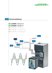
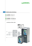
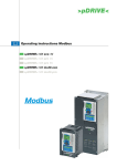
>pDRIVE< MX eco
>pDRIVE< MX pro
The Power Drives Company
Allgemeine Hinweise
Folgende Symbole werden Sie durch die Anleitung begleiten:
Hinweis, Tip !
Allgemeiner Hinweis, Unbedingt beachten !
Voraussetzung für eine erfolgreiche Inbetriebnahme sind eine korrekte Geräteauswahl, Projektierung und
Montage. Sollten Sie in diesem Zusammenhang weitere Fragen haben, so wenden Sie sich bitte an den
Lieferanten des Gerätes.
Kondensatorentladung !
Vor Arbeiten am Gerät ist nach dem Freischalten vom Netz die Kondensatorentladezeit von mindestens 15
Minuten abzuwarten, um sicherzustellen, daß das Gerät völlig spannungsfrei ist.
Automatischer Wiederanlauf !
Bei bestimmten Parametereinstellungen kann es vorkommen, daß der Frequenzumrichter nach einem Ausfall
und anschließender Netzzuschaltung automatisch wiederanläuft. Stellen Sie sicher, daß dadurch weder
Personen noch Einrichtungen gefährdet sind.
Inbetriebnahme und Service !
Arbeiten am Gerät dürfen nur von dafür qualifizierten Personen unter Beachtung der gültigen
Bedienungsanleitung und Vorschriften erfolgen. Im Fehlerfall können auch betriebsmäßig potentialfreie
Kontakte und/oder Baugruppen gefährliche Spannungen führen. Um eine Gefährdung auszuschließen, sind die
Vorschriften "Arbeiten unter Spannung" zu beachten.
Lieferbedingungen
Unseren Lieferungen und Leistungen liegen die "Allgemeinen Lieferbedingungen der Elektro- und
Elektronikindustrie Österreichs" neuester Ausgabe zugrunde.
Angaben in dieser Anleitung
Es ist unser Bestreben, unsere Erzeugnisse ständig zu verbessern und jeweils dem neuesten Stand der
technischen Entwicklung anzupassen. Änderungen der Angaben in dieser Anleitung, insbesondere von Maßen
und Abmessungen, bleiben daher jederzeit vorbehalten. Die Projektierungshinweise und Anschlußbeispiele
sind unverbindliche Vorschläge, für die wir insbesondere deshalb keine Gewähr übernehmen können, da die
anzuwendenden Bestimmungen von Art und Ort der Installation und Verwendung der Geräte abhängen.
Vorschriften
Der Anwender hat sicherzustellen, daß das Gerät sowie zugehörige Komponenten nach den jeweils gültigen
Vorschriften verwendet werden. Der Einsatz dieser Geräte in Wohngebieten ist ohne besondere Maßnahmen
zur Funkfrequenzentstörung nicht zulässig.
Schutzrechte
Wir bitten zu beachten, daß keine Gewähr dafür übernommen wird, daß die hier beschriebenen Schaltungen,
Geräte und Verfahren frei von Schutzrechten sind.
Bedienungsanleitung
>pDRIVE< MX eco & pro
Inhaltsverzeichnis
DEUTSCH
1
Hinweise.......................................................................................................................... 2
Sicherheit .................................................................................................................................................2
Empfang des Gerätes ..............................................................................................................................6
HAFF
Allgemeine Spezifikation ................................................................................................. 8
Qualität ...................................................................................................................................................10
Netzbedingungen ...................................................................................................................................11
Schutz der Anlage ..................................................................................................................................17
Verdrahtung und Anschluß ....................................................................................................................20
Bedienung ..................................................................................................................... 31
8 P01 022.02/02
Matrix-Bedieneinheit ..............................................................................................................................31
LED-Bedienfeld ......................................................................................................................................41
Inbetriebnahme ............................................................................................................. 60
Vorgangsweise.......................................................................................................................................60
Werkseinstellung ....................................................................................................................................63
ENGLISCH
64
Bitte beachten Sie weiters die ergänzenden Gerätedokumentationen Funktionsbeschreibung und Montageanleitung auf der beiliegenden CD-ROM.
Die vorliegende Anleitung umfaßt die Themen Montage, Verdrahtung und Anschluß
sowie Bedienung und Inbetriebnahme der >pDRIVE< MX eco & pro Frequenzumrichter.
1
Sehr geehrter Kunde!
Wir gratulieren Ihnen zum Erwerb dieses modernen Frequenzumrichters.
Hinweise
Sicherheit
Lesen Sie diese Anweisungen sorgfältig durch, bevor Sie den Frequenzumrichter
einsetzen und beachten Sie unbedingt nachfolgende Sicherheitshinweise !
• Es unterliegt der Verantwortung des Betreibers, daß die Schutzerdung aller Geräte den
geltenden internationalen und nationalen Normen bezüglich elektrischer Geräte
entspricht.
• Zahlreiche Komponenten des Frequenzumrichters, einschließlich der gedruckten
Schaltungen, werden über die Netzspannung versorgt. Berühren Sie diese Komponenten
nicht.
Verwenden Sie nur elektrisch isolierte Werkzeuge.
• Berühren Sie keine ungeschirmten Komponenten oder Klemmenschrauben, wenn das
Gerät unter Spannung steht.
• Schließen Sie die Klemmen PA/+ und PC/- oder die Kondensatoren des DCZwischenkreises nicht kurz.
• Montieren Sie alle Abdeckungen und schließen Sie diese, bevor Sie den Umrichter unter
Spannung setzen.
• Führen Sie vor jeglicher Wartung oder Reparatur am Frequenzumrichter folgende Arbeiten
aus:
− Unterbrechen Sie die Spannungsversorgung.
− Bringen Sie am Leistungs- oder Trennschalter des Frequenzumrichters ein Schild mit
dem Vermerk "NICHT EINSCHALTEN" an.
− Verriegeln Sie den Leistungs- oder Trennschalter in der geöffneten Stellung.
• Trennen Sie den Frequenzumrichter vor jeglichen Arbeiten vom Netz und gegebenenfalls
auch die externe Versorgung des Steuerteils. Warten Sie, bis die Ladungs-Anzeige des
Umrichters vollständig erloschen ist. Messen Sie die Spannung des DC-Zwischenkreises,
um zu überprüfen, ob die Gleichspannung unter 45 V liegt. Die LED des
Frequenzumrichters zur Anzeige vorhandener Spannung am DC-Zwischenkreis ist nicht
präzise genug.
2
8 P01 022.02/02
• Lesen Sie diese Anleitung vollständig und sorgfältig durch, bevor Sie den
Frequenzumrichter >pDRIVE< MX eco & pro installieren und in Betrieb setzen. Installation,
Einstellung und Reparaturen müssen durch qualifiziertes Personal erfolgen.
HAFF
Berührungsspannungen
Ein elektrischer Schlag kann zu Tod oder schwerer Körperverletzung führen.
Unsachgemäßer Betrieb des Umrichters
• Voraussetzung für eine erfolgreiche Inbetriebnahme sind eine korrekte Geräteauswahl,
Projektierung und Montage.
• Wenn der Umrichter längere Zeit nicht eingeschaltet war, ist die Leistung seiner
Elektrolytkondensatoren herabgesetzt.
• Schalten Sie im Fall eines längeren Betriebsstillstands den Umrichter mindestens alle
zwei Jahre und dann jeweils mindestens fünf Stunden lang ein, um die Leistung der
Kondensatoren wiederherzustellen und den Betrieb des Umrichters zu überprüfen. Es ist
empfehlenswert, den Umrichter nicht direkt an die Netzspannung anzuschließen, sondern
die Spannung stufenweise mit Hilfe eines Spartransformators zu erhöhen.
Wenn diese Vorkehrung nicht eingehalten wird, können Materialschäden auftreten.
8 P01 022.02/02
HAFF
Überprüfen der Netzspannung
Bevor Sie den Umrichter einschalten und konfigurieren, stellen Sie sicher, daß die
Netzspannung mit der Nennspannung des Umrichters kompatibel ist.
Bei nicht kompatibler Netzspannung kann der Umrichter beschädigt werden.
3
Entladung der Kondensatoren
Schalten Sie den Frequenzumrichter vor der
Durchführung von Arbeiten aus und warten Sie,
bis die rote LED, die die Ladung der
Kondensatoren anzeigt, erloschen ist. Messen
Sie dann die Spannung des DC-Busses.
>pDRIVE< MX eco & pro 4V0,75...4V18
Die rote LED leuchtet, wenn der DC-Bus unter
Spannung steht.
>pDRIVE< MX eco & pro ab 90kW
Messung der Spannung am DC-Bus
Die Spannung des DC-Busses kann 1000 V DC überschreiten.
Messen Sie die Spannung des DC-Busses wie nachfolgend beschrieben mit einem
geeigneten Meßgerät:
1. Unterbrechen Sie die Spannungsversorgung des Umrichters.
2. Warten Sie 15 Minuten, damit sich die Kondensatoren des DC-Busses entladen können.
3. Messen Sie die Spannung des DC-Busses zwischen den Klemmen PA/+ und PC/-, um zu
prüfen, ob die Spannung unter 45 V DC liegt.
Wenn sich die Kondensatoren des DC-Busses nicht vollständig entladen, wenden Sie
sich an Ihre lokale Vertretung (den Umrichter weder reparieren noch in Betrieb
setzen).
4
8 P01 022.02/02
HAFF
>pDRIVE< MX eco & pro 4V22...4V75
Unerwarteter Neustart des Umrichters
• Bevor Sie den >pDRIVE< MX eco & pro einschalten und konfigurieren, stellen Sie sicher,
daß der Eingang PWR ("Sicherer Halt", Power Removal) deaktiviert ist (Zustand 0), um
einen unvorhergesehenen Neustart zu vermeiden.
• Stellen Sie vor dem Einschalten oder beim Verlassen des Simulationsmode sicher, daß
die den Startbefehlen zugeordneten Eingänge deaktiviert sind (Zustand 0), da diese sofort
das Anlaufen des Motors bewirken könnten.
Eine Nichtbeachtung dieser Vorkehrungen kann zu Tod oder schwerwiegenden
Verletzungen führen.
HAFF
Wenn für die Sicherheit des Bedienpersonals ein unkontrolliertes Wiederanlaufen des
>pDRIVE< MX eco & pro ausgeschlossen sein muß, kann die elektronische Verriegelung
durch die Funktion "Sicherer Halt" (Power Removal) sichergestellt werden. Diese Funktion
bedingt die Verwendung eines Verdrahtungsschemas, das den Anforderungen der Kategorie
3 gemäß Norm EN 954-1 und dem Sicherheitsniveau 2 gemäß IEC/EN 61508 entspricht
(weitere Informationen finden Sie im Katalog oder auf der mit dem Umrichter gelieferten CDROM).
Die Power-Removal-Funktion (PWR) hat vor jedem Startbefehl Priorität.
8 P01 022.02/02
Zurücksetzen der Applikationsdaten
Das Zurücksetzen der Applikationsdaten erfolgt durch Laden des Makros M1.
Das Laden eines Makros überschreibt alle vorhandenen Applikationsdaten im aktiven
Parametersatz. Unverändert bleiben
Parametergruppen wie Motordaten,
Spracheinstellung, Fehlerspeicher, Betriebsstunden, Texte und grundlegende
Kommunikationseinstellungen.
Beim Rücksetzen der Applikationsdaten muß die Sicherheit der Anlage gewährleistet
werden!
Es muß sichergestellt werden, daß es z.B. nicht zu einem möglichen Anlauf durch
Vorbelegung der Digitaleingänge bzw. einem möglichen Öffnen einer Haltebremse
kommt.
Gerätetausch
Wenn Sie einen Frequenzumrichter ersetzen, prüfen Sie, ob die elektrischen
Anschlüsse am >pDRIVE< MX eco & pro den in dieser Anleitung angegebenen
Verdrahtungsanweisungen entsprechen.
5
Empfang des Gerätes
Handhabung des Umrichters
Um den Schutz des Frequenzumrichters vor der Montage sicherzustellen, sollte das Gerät
im verpackten Zustand bewegt und gelagert werden. Stellen Sie sicher, daß die
Umgebungsbedingungen zulässig sind.
Öffnen Sie die Verpackung und prüfen Sie, ob der >pDRIVE< MX eco & pro während des
Transports nicht beschädigt wurde.
Ist das Gerät beschädigt, installieren Sie den Umrichter nicht und nehmen Sie ihn
nicht im Betrieb !
Andernfalls können Materialschäden auftreten.
Die Umrichter >pDRIVE< MX eco & pro können ohne Hilfsmittel
ausgepackt werden.
Für größere Umrichtermodelle ist bei der Montage ein Hebezeug
notwendig. Sie sind daher mit Transportösen ausgestattet.
6
8 P01 022.02/02
HAFF
Der Hersteller trägt keine Verantwortung für Schäden, die während des Transports
oder beim Auspacken entstanden sind. Bitte informieren Sie in diesem Fall die
Versicherungsgesellschaft.
8 P01 022.02/02
HAFF
Überprüfen Sie, ob die Angaben auf dem Typenschild mit denen auf dem Bestellschein
übereinstimmen.
Lagerung
Lagertemperatur -25°C bis 70°C
Bei Lagerzeiten bis zu 5 Jahren ist auf Grund der relativ niederohmigen
Aufteilungswiderstände keine spezielle Behandlung des Frequenzumrichters notwendig.
Zur Sicherstellung der Lebensdauer empfehlen wir jedoch, den Umrichter etwa 1 Stunde an
Spannung zu legen, bevor eine Impulsfreigabe erfolgt. Man nennt diesen Vorgang auch
Formieren der ELKOs !!
7
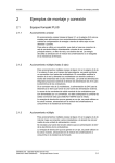
Allgemeine Spezifikation
>pDRIVE< MX eco & pro Frequenzumrichter zur Steuerung von DrehstromAsynchronmotoren und Drehstrom-Synchronmotoren nutzen modernste Bauteile und
Lösungen. Dies ermöglicht ein überaus kompaktes Design und anwenderfreundliche
Geräteeigenschaften.
Unser hohes Maß an Qualitätsbewußtsein erstreckt sich von den Grundanforderungen im
Lastenheft über die Entwicklung des Kühlsystems, des mechanischen Aufbaus, des
elektrischen Schaltplans und der einzelnen Funktionen bis letztlich hin zur der Gerätefertigung. Dieses Qualitätsniveau ist durch entsprechende Qualitätssicherungssysteme in
den einzelnen Unternehmensprozessen auch langfristig garantiert und wird jährlich von
unabhängiger Stelle entsprechend DIN EN ISO 9001 zertifiziert.
>pDRIVE< MX eco & pro Frequenzumrichter sind selbständig arbeitende Geräte mit interner
Versorgung der Steuerung und forcierter Lüftung. Sie besitzen ein eingebautes LEDBedienfeld und eine umfangreiche Steuerklemmleiste. Optimalen Bedienkomfort bietet die
abnehmbare Matrix-Bedieneinheit mit großem LCD-Display und Matrix-Rad.
J
UNetz
DC Vorladung
UDC
IGBTs
J
IMotor
UMotor
Motor control / Powerboard (Basis-Elektronik)
ISL (Internal Serial Link)
(galvanische Trennung)
interner
Applicative board (User interface)
Optionskarten
Bus
Klemmleistenerweiterung
Profibus, DeviceNet, ...
Sollwerte
Istwerte
8
Digitalsignale
Ein-/Ausgänge
RS 485 / PC
Modbus
CANopen
LCD
Bedieneinheit
8 P01 022.02/02
>pDRIVE< MX pro Frequenzumrichter sind für den motorischen und generatorischen Betrieb
von Motoren in beiden Drehrichtungen und beiden Energierichtungen geeignet. Sie können
die anfallende Bremsenergie über einen externen Bremswiderstand abführen oder durch
Vorschaltung einer Ein-/Rückspeiseeinheit >pDRIVE< LX plus die Energie ins Netz
zurückführen.
HAFF
Die >pDRIVE< MX eco Frequenzumrichter sind für den motorischen Betrieb von Motoren in
beiden Drehrichtungen geeignet. Für ein rasches Stillsetzen des Antriebes steht die Funktion
"Motorbremse" zur Verfügung, welche ohne zusätzliche Komponenten einen raschen
Tieflauf ermöglicht (siehe Katalog auf der beiliegenden CD).
Abhängig von den örtlichen Gegebenheiten und den Anforderungen an den Antrieb können
oder müssen die Grundgeräte durch Optionen ergänzt werden. Es stehen Optionen für den
Leistungspfad, Optionen der Steuerung und Bedienung wie auch mechanische Optionen zur
Verfügung (siehe Katalog auf der beiliegenden CD).
8 P01 022.02/02
HAFF
>pDRIVE< MX eco & pro Frequenzumrichter erfüllen die relevanten internationalen Normen
und Vorschriften von den EN-Normen über IEC-Normen bis hin zu UL und CSA Vorschriften.
9
Qualität
CE-Kennzeichnung
Alle Geräte und Anlagen der elektrischen Antriebstechnik können elektromagnetische
Störungen verursachen und durch solche gestört werden. Sie fallen daher seit 1.1.1996 in
den Geltungsbereich der EMV-Richtlinie 89/336/EWG.
>pDRIVE< MX eco & pro Frequenzumrichter haben eine Betriebsnennspannung, welche
eindeutig im Bereich von 50...1000 V AC bzw. 75...1500 V DC liegt. Sie fallen daher seit
1.1.1997 auch in den Geltungsbereich der Niederspannungsrichtlinie 73/23/EWG.
Durch die in den Frequenzumrichtern >pDRIVE< MX eco & pro eingebauten Funkentstörfilter
ist die Konformität mit EN 61800-3 und EN 50178 gewährleistet.
Die Frequenzumrichter >pDRIVE< MX eco & pro tragen eine CE-Kennzeichnung am
Leistungsschild. Um die entsprechenden Grenzwerte zu erreichen, ist es jedoch notwendig,
die Installationsvorschriften einzuhalten.
Installationsvorschriften
− Die >pDRIVE< MX eco & pro Frequenzumrichter haben standardmäßig ein
Funkentstörfilter für den Wohnbereich und ab 5,5 kW für den Industriebereich eingebaut.
Bei längeren Motorkabeln und für den Einsatz im Wohnbereich ist ein zusätzliches
externes Filter zur netzseitigen Reduktion der durch den Zwischenkreis hervorgerufenen
Stromoberschwingungen einzusetzen (siehe Katalog auf der beiliegenden CD).
− Montage auf einer gut geerdeten metallischen Montageplatte mit guter HF-Verbindung
zwischen Motorkabelschirm und Filter
− Verwendung von geschirmten Motorkabeln, beidseitig korrekter Anschluß bzw. Verlegung
des Motorkabels in einem metallischen, geschlossenen und durchgängig verbundenen
Kabelkanal
− Verwendung eines Ausgangs-Motor-Filters bei größeren Motorkabellängen (siehe Katalog
auf der beiliegenden CD)
− Verwendung und korrekter Anschluß von geschirmten Steuerkabeln (siehe Kapitel
"Verdrahtungshinweise für Leistungs- und Steuerkabel", Seite 28)
− Erdung des Frequenzumrichters mit mindestens 10 mm2 für Personenschutz
− Getrennte Verlegung der Motorleitungen von anderen Kabeln, besonders von
Steuerleitungen
10
8 P01 022.02/02
>pDRIVE< MX eco & pro Frequenzumrichter sind ein Produkt der eingeschränkten
Vertriebsklasse nach IEC 61800-3. In einer Wohnumwelt kann dieses Produkt
hochfrequente Störungen verursachen, woraufhin der Anwender aufgefordert werden
kann, geeignete Maßnahmen zu ergreifen.
HAFF
Frequenzumrichter sind jedoch nicht als Maschinen mit mindestens einem mechanisch
beweglichen Teil zu sehen. Sie fallen daher nicht in den Geltungsbereich der
Maschinenrichtlinie 98/37/EEC.
Netzbedingungen
Netzspannung
Die >pDRIVE< MX eco & pro Geräte sind für folgende Netzspannungen konzipiert:
3 AC 380 V -15 % bis 440 V +10 %, 50 Hz ± 5 %
3 AC 380 V -15 % bis 480 V +10 %, 60 Hz ± 5 %
Die tatsächliche Netz-Nennspannung ist mittels Parameter am Umrichter einzustellen.
Dadurch erfolgt die optimale Anpassung der Unterspannungs-Schutzfunktion.
Ungeerdete Netze
HAFF
Der Einsatz der >pDRIVE< MX eco & pro Frequenzumrichter ist grundsätzlich in allen
Netzvarianten zulässig.
Bei ungeerdeten Netzen (typisch bei Industrienetzen) muß das eingebaute
Funkentstörfilter durch Umschalten/Umklemmen entsprechend angepaßt werden. In
diesem Fall beträgt die maximal zulässige Taktfrequenz 4 kHz.
8 P01 022.02/02
>pDRIVE< MX eco & pro 4V0,75...4V75
11
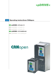
>pDRIVE< MX eco 4V90...4V132
>pDRIVE< MX pro 4V90/110...4V110/132
8 P01 022.02/02
HAFF
>pDRIVE< MX eco 4V160...4V200
>pDRIVE< MX pro 4V132/160...4V160/200
12
>pDRIVE< MX eco 4V250...4V630
>pDRIVE< MX pro 4V200/250...4V500/630
Aus Gründen des Personenschutzes ist in IT-Netzen nur der Einsatz von speziellen
RFI-Filtern mit sehr geringem Ableitstrom zulässig (Erhöhung der Erdkapazitäten, ...).
Die externen Filter Option >pDRIVE< RFI sind nicht für IT-Netze geeignet !
8 P01 022.02/02
HAFF
Bei ungeerdeten Netzen hat ein einpoliger Erdschluß im speisenden Netz keinen Einfluß auf
die Funktion des Umrichters. Tritt der Erdschluß im Motor oder Motorkabel auf, schaltet sich
der Umrichter ab. Die Erkennung ist jedoch stark von der Erdkapazität des Netzes abhängig.
13
Funkstörungen
Die >pDRIVE< MX eco & pro Umrichter haben standardmäßig ein Funkentstörfilter
eingebaut. Diese Filter erfüllen abhängig von der Gerätegröße die Anforderungen der
Kategorien C2 bzw. C3 entsprechend EN/IEC 61800-3.
Gerät
Kategorie
C2 Wohnbereich – EMV-kundiger Anwender
>pDRIVE< MX eco & pro 4V0,75
(EN 55011 Klasse A Gruppe 1)
... 4V4,0
>pDRIVE< MX eco & pro ab 4V5,5 C3 Industriebereich
(EN 55011 Klasse A Gruppe 2)
>pDRIVE< MX eco & pro Frequenzumrichter sind ein Produkt der eingeschränkten
Vertriebsklasse nach IEC 61800-3. In einer Wohnumwelt kann dieses Produkt
hochfrequente Störungen verursachen, woraufhin der Anwender aufgefordert werden
kann, geeignete Maßnahmen zu ergreifen.
HAFF
Für den Einsatz von Umrichtern höherer Leistungen in Wohngebieten und bei längeren
Motorkabeln müssen zusätzliche Filter Option >pDRIVE< RFI eingesetzt werden (siehe
Katalog auf der beiliegenden CD).
Durch die Verwendung eines Diodengleichrichters auf der Eingangsseite des Umrichters
treten im Netzstrom harmonische Oberschwingungen auf, welche wiederum zu einer
Spannungsverzerrung des speisenden Netzes führen.
Zur Reduktion dieser Stromoberschwingungen und zur Verringerung des
Gesamtnetzstromes stehen verschiedene Möglichkeiten zur Verfügung:
− Einsatz einer Gleichstrom-Glättungsdrossel Option >pDRIVE< DCL
Diese lose Option ist für die Geräte >pDRIVE< MX eco & pro 4V0,75...4V75 in Schutzart
IP20 verfügbar.
Für >pDRIVE< MX eco & pro ab 90 kW ist eine Drosselbox in Schutzart IP31 verfügbar.
Nähere Informationen finden Sie im Katalog auf der beiliegenden CD.
− Verwendung einer Drehstromdrossel Option >pDRIVE< NDU in den Netzleitungen
Für alle Geräte >pDRIVE< MX eco & pro ab 4V15 ist eine angepaßte Netzdrossel als lose
Option verfügbar.
Nähere Informationen finden Sie im Katalog auf der beiliegenden CD.
− Installation eines Netzstromoberschwingungsfilters Option >pDRIVE< HF
Die Option ist für die Geräte >pDRIVE< MX eco & pro ab 4V4,0 verfügbar.
Nähere Informationen finden Sie im Katalog auf der beiliegenden CD.
− 12-Puls-Schaltung
Dabei erfolgt die Einspeisung über einen eigenen Trafo mit zwei phasenverschobenen
Sekundärwicklungen.
Standardmäßig sind die Geräte >pDRIVE< MX eco 4V500...4V630 bzw. >pDRIVE< MX
pro 4V400/500...4V500/630 für 12-Puls-Einspeisung vorbereitet.
14
8 P01 022.02/02
Netzstromoberschwingungen / Netzspannungsverzerrungen
12-Puls-Einspeisung
Die Frequenzumrichter >pDRIVE< MX eco 4V500...4V630 bzw. >pDRIVE< MX pro
4V400/500...4V500/630 sind standardmäßig mit zwei parallelen Eingangsgleichrichtern
ausgestattet und somit auch für eine 12-Puls-Gleichrichtung geeignet. Dabei erfolgt die
Einspeisung über einen eigenen Trafo mit zwei phasenverschobenen Sekundärwicklungen
(z.B. Yy6d5).
Auf der Primärseite des Trafos sind die 5. und 7. Stromoberschwingung praktisch nicht
mehr vorhanden, da sie durch die versetzten Trafowicklungen aufgehoben werden.
Zur Sicherstellung einer gleichmäßigen Stromaufteilung muß der Trafo die Toleranzwerte einhalten:
Toleranz der Übersetzungsverhältnisse ± 0,3 % von üNENN
Toleranz der relativen Kurzschlußspannung ± 5,0 % von uK_NENN
8 P01 022.02/02
HAFF
*) DC-Drosseln oder alternativ Netzdrosseln sind nur notwendig, wenn ein
Transformator für mehrere Umrichter
verwendet wird oder wenn die Trafoleistung deutlich größer als die
Umrichterleistung ist (siehe Kapitel
"Netzimpedanz / Kurzschlußstrom",
Seite 15").
Die Funkentstörfilter, die standardmäßig in den >pDRIVE< MX eco & pro eingebaut
sind, müssen bei 12-Puls-Einspeisung auf Einstellung "IT-Netze" umgeklemmt
werden.
Netzimpedanz / Kurzschlußstrom
Die >pDRIVE< MX eco & pro Frequenzumrichter sind entsprechend eines maximal
zulässigen Netzkurzschlußstromes am Einspeisepunkt dimensioniert (Werte siehe Tabelle im
Katalog auf der beiliegenden CD).
Durch die Verwendung von Drosseln (Option >pDRIVE< DCL oder Option >pDRIVE<
NDU) sind wesentlich höhere Netzkurzschlußleistungen möglich, ohne die Betriebssicherheit des Umrichters zu beeinträchtigen.
Blindstromkompensationsanlagen
Frequenzumrichter rufen im speisenden Netz Stromoberschwingungen hervor. Ist eine
Blindstromkompensationsanlage im Einsatz, werden deren Kondensatoren durch die
Oberschwingungen zusätzlich belastet.
Zum Schutz vor Überlastung wird daher die Verdrosselung dieser Anlagenteile
empfohlen.
15
Schalthäufigkeit
Die >pDRIVE< MX eco & pro Umrichter können direkt mit dem Netzschütz ein- und
ausgeschaltet werden, welches komfortabel über einen Relaisausgang der Umrichter
gesteuert werden kann.
Es empfiehlt sich jedoch bei häufigen Start-/Stop-Befehlen, diese über die digitalen
Steuereingänge (oder über einen seriellen Bus) direkt an die Elektronik des Umrichters zu
legen.
Schalthäufigkeit
Der Umrichter wird über das Zu- und Wegschalten der Netzspannung gesteuert.
Wie oben, jedoch mit dauerhafter Versorgung
der Gerätelüfter (nur bei MX eco 4V132...4V630
bzw. MX pro 4V110/132…4V500/630 möglich)
Abschalten des Motors durch ein Motorschütz
max. 60 Schaltungen pro Stunde
(Sicherheitskategorie 1, Stopkategorie 0)
nur abhängig vom Netzschütz
Elektronische Start-/Stopbefehle über die
Digitaleingänge des Umrichters
Elektronische Sperre des Umrichters mittels
Steuereingang PWR "Sicherer Halt"
abhängig vom Motorschütz
(Sicherheitskategorie 1, Stopkategorie 0)
Beliebig
Beliebig
(Sicherheitskategorie 3, Stopkategorie 0
oder 1)
Die Steuerung der Gerätelüfter erfolgt automatisch in Abhängigkeit vom Startbefehl
und einer temperaturabhängigen Nachlauffunktion (siehe Katalog auf der
beiliegenden CD).
16
8 P01 022.02/02
Umrichtersteuerung
HAFF
Durch den geprüften Steuereingang "PWR" ist ein "Sicherer Halt" des Antriebes nach
Sicherheitskategorie entsprechend EN 954-1 (bzw. Entwurf IEC/EN 61800-5-2)
gewährleistet. Ein Netz- oder Motorschütz kann somit eingespart werden.
Nähere Informationen finden Sie im Katalog auf der beiliegenden CD.
Schutz der Anlage
Verantwortlichkeit
Es liegt in der Verantwortlichkeit des Anwenders, die >pDRIVE< MX eco & pro
Frequenzumrichter in das Schutz- und Sicherheitskonzept der Anlage oder Maschine
einzubinden.
Alle angeführten Schaltungsempfehlungen und Projektierungshinweise sind daher lediglich
als Vorschläge zu verstehen, die an die örtlichen Gegebenheiten und Bestimmungen
hinsichtlich Installation und Verwendung angepaßt werden müssen.
Dies trifft im Besonderen auf die Sicherheitsvorschriften für Maschinen, die EMVVorschriften und die allgemeinen Personenschutzbestimmungen zu.
Frequenzen > 60 Hz
HAFF
Für den Betrieb von Motoren und Antrieben mit Frequenzen größer als 60 Hz muß die
Eignung der verwendeten Komponenten geprüft werden.
Eine Rückfrage beim Motoren- bzw. Maschinenhersteller sollte unbedingt erfolgen. 4...8polige Motoren sind üblicherweise für einen Betrieb bis 100 Hz geeignet.
8 P01 022.02/02
FI-Schutzschalter
Frequenzumrichter, besonders solche mit zusätzlichen Funkentstörfiltern >pDRIVE< RFI und
geschirmten Motorkabeln, führen einen erhöhten Ableitstrom gegen Erde.
Er ist abhängig von:
• der Länge des Motorkabels
• der Art der Verlegung und ob das Motorkabel geschirmt oder ungeschirmt ausgeführt
ist
• der eingestellten Taktfrequenz
• der Verwendung des zusätzlichen Funkentstörfilters >pDRIVE< RFI
• der Erdung des Motors am Standort (geerdet oder nicht geerdet)
Im Einschaltaugenblick kann es insbesondere durch die Kondensatoren des Filters
zur ungewollten Auslösung eines FI-Schutzschalters kommen. Ebenso können die
Erdkapazitäten im Betrieb zu einer Fehlauslösung führen.
Andererseits besteht durch die Netzgleichrichtung am Eingang des Umrichters die
Möglichkeit der Blockierung der Auslösefunktion durch Gleichstromanteile.
17
Es sollte daher folgendes beachtet werden:
• Nur kurzzeitverzögerte und pulsstromsensitive FI-Schutzschalter mit wesentlich
höherem Auslösenennstrom verwenden.
• Andere Verbraucher durch einen eigenen FI-Schutzschalter absichern.
• FI-Schutzschalter vor einem Umrichter stellen keinen absolut zuverlässigen Schutz bei
direktem Berühren dar !! Sie sollten daher immer in Verbindung mit anderen Schutzmaßnahmen eingesetzt werden.
• Die >pDRIVE< MX eco & pro Frequenzumrichter haben keine strombegrenzende
Wirkung (bei Fehlerströmen) und verletzen damit nicht die Nullungsbedingungen.
Bei Anlagen mit großen Kabellängen kann der Ableitstrom, abhängig von den Gegebenheiten, durchaus größer 100 mA sein !!
Die eingebaute Erdschlußüberwachung hat keine strombegrenzende Wirkung. Sie ist
ein Geräteschutz und kein Personenschutz.
Nähere Informationen zur Schutzfunktion finden Sie im Katalog unter Kapitel
"Sicherer Halt".
Ab- und Zuschalten des Motors
Alternativ zu Verwendung des Steuereingangs PWR "Sicherer Halt" kann ein
Sicherheitsschalter oder ein Motorschütz zum Ab- und Zuschalten des Motors eingesetzt
werden. Da der Umrichter den jeweiligen Schaltzustand erkennt, ist das Risiko einer
Zerstörung oder Störabschaltung ausgeschlossen.
Nach dem Zuschalten erfolgt der Wiederanlauf mittels der Funktion "Fangen" (siehe Katalog
auf der beiliegenden CD).
Nähere Informationen finden Sie in der Funktionsbeschreibung unter Parameter C6.08
"Motorschützsteuerung".
18
8 P01 022.02/02
Die >pDRIVE< MX eco & pro Geräte enthalten standardmäßig die Schutzfunktion "Sicherer
Halt" (Power Removal, Zertifikat Nr. 72148-2 /2006), welche ein unbeabsichtigtes Anlaufen
des Motors verhindert. Diese Funktion erfüllt bei entsprechender Verdrahtung dem
Maschinenstandard EN 954-1 Sicherheitskategorie 3, der Norm IEC/EN 61508 SIL2 für
funktionale Sicherheit und dem Power Drive System Standard IEC/EN 61800-5-2.
HAFF
Sperren des Frequenzumrichters
Wiedereinschaltautomatik
Die interne Funktion "Wiedereinschaltautomatik" schaltet den Umrichter nach jeder
Netzzuschaltung bzw. Netzwiederkehr selbsttätig ein, ohne daß der Netzausfall quittiert
werden muß. Sie ist besonders bei Antrieben, die nicht über ein Feldbussystem in die
Anlagensteuerung eingebunden sind, eine wichtige und wertvolle Funktion zur Erhöhung der
Verfügbarkeit.
Der automatische Wiederanlauf erfolgt bei:
• Zuschaltung der Netzspannung (nur bei 2-Draht Steuerung und abhängig vom
gewählten Unterspannungsverhalten)
• nach einem Netzausfall (nur bei 2-Draht Steuerung und abhängig vom gewählten
Unterspannungsverhalten)
• bei Beendigung des Standby-Mode
• nach jeder Störungsquittierung (nur bei 2-Draht Steuerung – pegelbewertet)
HAFF
• nach einem Schnellhalt oder Nothalt (nur bei 2-Draht Steuerung – pegelbewertet)
Überspannungs-Schutzbeschaltung
8 P01 022.02/02
Alle Induktivitäten wie Relais, Schütze, magnetische Bremsen usw. müssen mit einer
Überspannungsbeschaltung ausgestattet sein. Sie verhindert Fehlfunktionen der
konventionellen Gerätesteuerung wie auch des Feldbusses.
Für Gleichstrom-Steuerkreise ist eine Freilaufdiode vorzusehen.
Für Wechselstrom-Steuerkreise ist die R/C-Beschaltung einer Beschaltung mit Varistoren
vorzuziehen, da damit auch die Anstiegszeiten und nicht nur der Scheitelwert der
Überspannung reduziert werden.
19
Verdrahtung und Anschluß
Verdrahtungsschema >pDRIVE< MX eco
Nachfolgende Darstellungen zeigen die typische Verdrahtung der >pDRIVE< MX eco
Frequenzumrichter inklusive Optionen, die je nach Anwendungsfall zum Schutz der Anlage
oder des Gerätes erforderlich sein können.
>pDRIVE< MX eco 4V500...4V630
20
8 P01 022.02/02
HAFF
>pDRIVE< MX eco 4V0,75...4V400
>pDRIVE< MX...... Frequenzumrichter
HS........................ Hauptschalter (Einsatz bei Bedarf entsprechend der örtlichen
Vorschriften)
NH ....................... Netzsicherungen laut Tabelle "Sicherungen und Kabelquerschnitte", Seite
25; (unbedingt erforderlich)
NS........................ Netzschütz (Einsatz bei Bedarf entsprechend der örtlichen Vorschriften)
>pDRIVE< NDU ... Netzdrossel
Option zur netzseitigen Reduktion der durch den Zwischenkreis
hervorgerufenen Stromoberschwingungen, Verwendung alternativ zur
Option >pDRIVE< HF und >pDRIVE< DCL
>pDRIVE< HF ...... Netzstrom-Oberschwingungsfilter
Option zur netzseitigen Reduktion der durch den Zwischenkreis
hervorgerufenen Stromoberschwingungen, Verwendung alternativ zur
Option >pDRIVE< NDU und >pDRIVE< DCL
8 P01 022.02/02
HAFF
>pDRIVE< RFI...... Funkentstörfilter
Option zum Einsatz des Umrichters entsprechend Kategorie C1 bzw. C2
nach EN 61800-3 "Einsatz in 1. Umgebung - Wohngebiet"
internes Filter ....... standardmäßig eingebautes Funkentstörfilter
entspricht Kategorie C3 entsprechend EN 61800-3 "Einsatz in
Industriegebieten" (Kategorie C2 bis >pDRIVE< MX eco 4V4,0)
>pDRIVE< AMF ... Ausgangs-Motor-Filter
Option zur Reduktion der Spannungsspitzen am Motor bei langen
Motorkabeln
>pDRIVE< SMF.... Sinus-Motor-Filter
Option für nahezu sinusförmigen Motorstrom und vollständige
Vermeidung von Zusatzgeräuschen am Motor
>pDRIVE< DCL .... DC-Drossel
Option zur Reduktion der Stromoberschwingungen, Verwendung
alternativ zur Option >pDRIVE< NDU
bei MX eco 4V0,75...4V75 als lose Option, darüber als Anbauoption
verfügbar
1. Die Aufteilung der Umrichter-Einspeisung muß bei Verwendung von Netzdrosseln vor
diesen erfolgen.
2. Die Sicherungsüberwachung ist erforderlich, um die Gleichrichter vor ungleicher
Belastung zu schützen. Sie muß auf Netzschütz oder Impulssperre (z.B. Digitaleingang
"Externe Störung") wirken.
>pDRIVE< MX eco Frequenzumrichter sind ein Produkt der eingeschränkten
Vertriebsklasse nach IEC 61800-3. In einer Wohnumwelt kann dieses Produkt
hochfrequente Störungen verursachen, woraufhin der Anwender aufgefordert werden
kann, geeignete Maßnahmen zu ergreifen.
21
Verdrahtungsschema >pDRIVE< MX pro
Nachfolgende Darstellungen zeigen die typische Verdrahtung der >pDRIVE< MX pro
Frequenzumrichter inklusive Optionen, die je nach Anwendungsfall zum Schutz der Anlage
oder des Gerätes erforderlich sein können.
>pDRIVE< MX pro 4V200/250...4V315/400
22
8 P01 022.02/02
HAFF
>pDRIVE< MX pro 4V0,75...4V160/200
8 P01 022.02/02
HAFF
>pDRIVE< MX pro 4V400/500...4V500/630
>pDRIVE< MX...... Frequenzumrichter
HS........................ Hauptschalter (Einsatz bei Bedarf entsprechend der örtlichen
Vorschriften)
NH ....................... Netzsicherungen laut Tabelle "Sicherungen und Kabelquerschnitte", Seite
25; (unbedingt erforderlich)
NS........................ Netzschütz (Einsatz bei Bedarf entsprechend der örtlichen Vorschriften)
>pDRIVE< NDU ... Netzdrossel
Option zur netzseitigen Reduktion der durch den Zwischenkreis
hervorgerufenen Stromoberschwingungen, Verwendung alternativ zur
Option >pDRIVE< HF und >pDRIVE< DCL
>pDRIVE< HF ...... Netzstrom-Oberschwingungsfilter
Option zur netzseitigen Reduktion der durch den Zwischenkreis
hervorgerufenen Stromoberschwingungen, Verwendung alternativ zur
Option >pDRIVE< NDU und >pDRIVE< DCL
>pDRIVE< RFI...... Funkentstörfilter
Option zum Einsatz des Umrichters entsprechend Kategorie C1 bzw. C2
nach EN 61800-3 "Einsatz in 1. Umgebung - Wohngebiet"
internes Filter ....... standardmäßig eingebautes Funkentstörfilter
entspricht Kategorie C3 entsprechend EN 61800-3 "Einsatz in
Industriegebieten" (Kategorie C2 bis >pDRIVE< MX pro 4V4,0)
>pDRIVE< AMF ... Ausgangs-Motor-Filter
Option zur Reduktion der Spannungsspitzen am Motor bei langen
Motorkabeln
>pDRIVE< SMF.... Sinus-Motor-Filter
Option für nahezu sinusförmigen Motorstrom und vollständige
Vermeidung von Zusatzgeräuschen am Motor
23
>pDRIVE< DCL ....DC-Drossel
Option zur Reduktion der Stromoberschwingungen, Verwendung
alternativ zur Option >pDRIVE< NDU
bei MX pro 4V0,75...4V75 als lose Option, bei MX pro
4V90/110...4V500/630 als Anbauoption verfügbar
>pDRIVE< BU ......Bremssteller
Externe Option für >pDRIVE< MX pro 4V200/250 … 4V500/630
>pDRIVE< BR ......Bremswiderstand
Option für rasche Tieflaufzeit oder kurzzeitige generatorische Lasten.
DC+ / DC- ............Energieeinspeisung aus einer DC-Schiene; alternativ zur 3AC
Netzeinspeisung
8 P01 022.02/02
>pDRIVE< MX pro Frequenzumrichter sind ein Produkt der eingeschränkten
Vertriebsklasse nach IEC 61800-3. In einer Wohnumwelt kann dieses Produkt
hochfrequente Störungen verursachen, woraufhin der Anwender aufgefordert werden
kann, geeignete Maßnahmen zu ergreifen.
HAFF
1. Die Aufteilung der Umrichter-Einspeisung muß bei Verwendung von Netzdrosseln vor
diesen erfolgen.
2. Die Sicherungsüberwachung ist erforderlich, um die Gleichrichter vor ungleicher
Belastung zu schützen. Sie muß auf Netzschütz oder Impulssperre (z.B. Digitaleingang
"Externe Störung") wirken.
24
Sicherungen und Kabelquerschnitte
Die >pDRIVE< MX eco & pro Frequenzumrichter beinhalten keine Eingangssicherungen.
Diese sind extern für den Fall vorzusehen, daß die elektronischen Schutzmechanismen des
Umrichters versagen. Sie stellen daher einen Sekundärschutz des Umrichters dar, um die
Leistungskabel vor Überlast und den Eingangsgleichrichter im Falle eines internen Kurzschlusses zu schützen.
Die angeführten Querschnitte für 3-Leiter-Kabel sind Richtwerte für eine Kabelverlegung in
Luft bei max. 40°C Umgebungstemperatur, basierend auf den Vorschriften ÖVN EN 1 und
VDE 0100.
Die Leitungen im Schrank sind entsprechend der Spezifikation für Einzelleiter XLPE/EPR
Kupfer 90°C ausgelegt.
Die Motorkabel sind auf den max. Dauerstrom ausgelegt. Sie gelten für 0...100 Hz (bis
300 Hz erhöhen sich die Kabelverluste um ca. 25 % aufgrund des Skin-Effekts).
HAFF
Für andere Umgebungsbedingungen und abweichende Vorschriften müssen die
Kabelquerschnitte entsprechend angepaßt werden.
Netzeinspeisung
Vor- bzw.
AbzweigCu-Kabel
mm2
sicherung
8 P01 022.02/02
1.)
10 A
10 A
10 [16] A
16 [20] A
20 [25] A
25 [40] A
32 [40] A
40 [63] A
63 [80] A
63 [80] A
63 [80] A
80 [100] A
100 [125] A
125 [160] A
160 [200] A
200 [250] A
250 A
250 A
315 A
400 A
500 A
630 A
800 A
1000 A
1000 A
1250 A
1600 A
3 x 2,5
3 x 2,5
3 x 1,5 [2,5]
3 x 2,5
3 x 2,5 [4]
3 x 4 [6]
3 x 4 [6]
3 x 6 [16]
3 x 16 [25]
3 x 16 [25]
3 x 16 [25]
3 x 25 [35]
3 x 35 [50]
3 x 50 [70]
3 x 70 [95]
3 x 95 [120]
3 x 120
3 x 120
3 x 185
2 x (3 x 120)
2 x (3 x 150)
2 x (3 x 185)
3 x (3 x 185)
4 x (3 x 185)
4 x (3 x 185)
4 x (3 x 240)
6 x (3 x 240)
Frequenzumrichter
Motorabgang
Netzsicherung
"Umrichterschutz" "sf"
Leitungen im
>pDRIVE<
Schrank mm2
MX eco
(je Phase)
Max.
max.
Motorkabel
DauerAnschluß mm2 3.)
strom
10 A (sf)
10 A (sf)
10 [16] A (sf)
16 [20] A (sf)
16 [25] A (sf)
25 [40] A (sf)
25 [40] A (sf)
40 [63] A (sf)
50 [80] A (sf)
50 [80] A (sf)
63 [80] A sf A
80 [100] A sf A
100 [125] A sf A
125 [160] A sf B
160 [200] A sf B
200 [250] A sf B
250 A sf
C
250 A sf
C
315 A sf
C
400 A sf
D
500 A sf
D
630 A sf
E
800 A sf
F
800 A sf
F
900 A sf
F
2 x 630 A sf 2.) E
2 x 800 A sf 2.) F
1,5
1,5
1,5 [2,5]
2,5
2,5 [4]
4 [6]
4 [6]
6 [10]
10 [16]
10 [16]
10 [16]
16 [25]
25 [35]
35 [50]
50 [70]
70 [95]
95
95
120
185
2 x 120
2 x 150
3 x 150
3 x 150
3 x 185
2 x 2 x 150
2 x 3 x 150
2,3 A
4,1 A
5,8 A
7,8 A
10,5 A
14,3 A
17,6 A
27,7 A
33 A
41 A
48 A
66 A
79 A
94 A
116 A
160 A
179 A
215 A
259 A
314 A
387 A
481 A
616 A
671 A
759 A
941 A
1188 A
4V0,75
4V1,5
4V2,2
4V3,0
4V4,0
4V5,5
4V7,5
4V11
4V15
4V18
4V22
4V30
4V37
4V45
4V55
4V75
4V90
4V110
4V132
4V160
4V200
4V250
4V315
4V355
4V400
4V500
4V630
6 mm2
6 mm2
6 mm2
6 mm2
6 mm2
6 mm2
6 mm2
16 mm2
35 mm2
35 mm2
50 mm2
50 mm2
50 mm2
120 mm2
120 mm2
120 mm2
M10
M10
M10
M10
M12
M12
M12
M12
M12
M12
M12
3 x 1,5
3 x 1,5
3 x 1,5
3 x 1,5
3 x 1,5
3 x 2,5
3 x 2,5
3x4
3x6
3 x 10
3 x 10
3 x 16
3 x 25
3 x 35
3 x 50
3 x 70
3 x 95
3 x 120
3 x 150
2 x (3 x 95)
2 x (3 x 120)
2 x (3 x 150)
3 x (3 x 150)
3 x (3 x 150)
3 x (3 x 185)
4 x (3 x 185)
5 x (3 x 185)
25
Netzeinspeisung
Vor- bzw.
AbzweigCu-Kabel
sicherung
mm2
1.)
10 A
10 A
10 [16] A
16 [20] A
20 [25] A
25 [40] A
32 [40] A
40 [63] A
63 [80] A
63 [80] A
63 [80] A
80 [100] A
100 [125] A
125 [160] A
160 [200] A
200 [250] A
3 x 2,5
3 x 2,5
3 x 1,5 [2,5]
3 x 2,5
3 x 2,5 [4]
3 x 4 [6]
3 x 4 [6]
3 x 6 [16]
3 x 16 [25]
3 x 16 [25]
3 x 16 [25]
3 x 25 [35]
3 x 35 [50]
3 x 50 [70]
3 x 70 [95]
3 x 95 [120]
Frequenzumrichter
Motorabgang
Netzsicherung
"Umrichterschutz" "sf"
Leitungen im
>pDRIVE<
Schrank mm2
MX pro
(je Phase)
Max.
max.
Motorkabel
DauerAnschluß mm2 3.)
strom
10 A (sf)
10 A (sf)
10 [16] A (sf)
16 [20] A (sf)
16 [25] A (sf)
25 [40] A (sf)
25 [40] A (sf)
40 [63] A (sf)
50 [80] A (sf)
50 [80] A (sf)
63 [80] A sf
80 [100] A sf
100 [125] A sf
125 [160] A sf
160 [200] A sf
200 [250] A sf
1,5
1,5
1,5 [2,5]
2,5
2,5 [4]
4 [6]
4 [6]
6 [10]
10 [16]
10 [16]
10 [16]
16 [25]
25 [35]
35 [50]
50 [70]
70 [95]
4V0,75
4V1,5
4V2,2
4V3,0
4V4,0
4V5,5
4V7,5
4V11
4V15
4V18
4V22
4V30
4V37
4V45
4V55
4V75
2,3 A
4,1 A
5,8 A
7,8 A
10,5 A
14,3 A
17,6 A
27,7 A
33 A
41 A
48 A
66 A
79 A
94 A
116 A
160 A
6 mm2
6 mm2
6 mm2
6 mm2
6 mm2
6 mm2
6 mm2
16 mm2
35 mm2
35 mm2
50 mm2
50 mm2
50 mm2
120 mm2
120 mm2
120 mm2
3 x 1,5
3 x 1,5
3 x 1,5
3 x 1,5
3 x 1,5
3 x 2,5
3 x 2,5
3x4
3x6
3 x 10
3 x 10
3 x 16
3 x 25
3 x 35
3 x 50
3 x 70
95
120
150
185
2 x 120
2 x 150
3 x 150
2 x 2 x 120
2 x 2 x 150
4V90/110
4V110/132
4V132/160
4V160/200
4V200/250
4V250/315
4V315/400
4V400/500
4V500/630
179 A
215 A
259 A
314 A
387 A
481 A
616 A
759 A
941 A
M10
M10
M10
M12
M12
M12
M12
M12
M12
3 x 95
3 x 120
3 x 150
2 x (3 x 95)
2 x (3 x 120)
2 x (3 x 150)
3 x (3 x 150)
3 x (3 x 185)
4 x (3 x 185)
95
120
185
2 x 120
2 x 150
3 x 150
3 x 185
2 x 2 x 150
2 x 3 x 150
4V90/110
4V110/132
4V132/160
4V160/200
4V200/250
4V250/315
4V315/400
4V400/500
4V500/630
215 A
259 A
314 A
387 A
481 A
616 A
759 A
941 A
1188 A
M10
M10
M10
M12
M12
M12
M12
M12
M12
3 x 120
3 x 150
2 x (3 x 95)
2 x (3 x 120)
2 x (3 x 150)
3 x (3 x 150)
3 x (3 x 185)
4 x (3 x 185)
5 x (3 x 185)
A
A
A
B
B
B
3 x 120
3 x 185
2 x (3 x 120)
2 x (3 x 120)
2 x (3 x 150)
2 x (3 x 185)
3 x (3 x 185)
4 x (3 x 185)
4 x (3 x 240)
250 A sf
C
315 A sf
C
350 A sf
D
400 A sf
D
500 A sf
E
630 A sf
F
800 A sf
F
2.)
2 x 500 A sf E
2 x 630 A sf 2.) F
Leistung 2 – hohe Dauerlast
250 A
315 A
400 A
500 A
630 A
800 A
1000 A
1250 A
1600 A
1.)
3 x 120
3 x 185
2 x (3 x 120)
2 x (3 x 150)
2 x (3 x 185)
3 x (3 x 185)
4 x (3 x 185)
4 x (3 x 240)
6 x (3 x 240)
250 A sf
C
315 A sf
C
400 A sf
D
500 A sf
D
630 A sf
E
800 A sf
F
900 A sf
F
2.)
2 x 630 A sf E
2 x 800 A sf 2.) F
Empfohlene Vorsicherungen passend für Motor-Direktanlauf bei Bypass-Schaltung.
2 x 3polige Sicherungen wegen paralleler Einspeisung
3.)
Bei Bypass-Betrieb muß das Motorkabel auf die Vor- bzw. Abzweigsicherung ausgelegt
werden !
[ ] Bei Verwendung der Umrichter ohne die Option >pDRIVE< DCL, >pDRIVE< NDU oder
>pDRIVE< HF müssen die Werte in eckiger Klammer berücksichtigt werden.
2.)
26
8 P01 022.02/02
250 A
315 A
400 A
400 A
500 A
630 A
800 A
1000 A
1250 A
HAFF
Leistung 1 – hohe Überlast
Zum Schutz des Gleichrichters bei Kurzschluß sollen die verwendeten Sicherungen die
folgenden Betriebs-Ausschalt-I2t-Werte (bezogen auf 10 ms) nicht überschreiten:
A
B
C
D
E
F
5.103 A2s
50.103 A2s
160.103 A2s
320.103 A2s
780.103 A2s
1000.103 A2s
Falls die Netzsicherungen ausfallen, ist im Umrichter bereits ein Primärschaden
aufgetreten. Ein Tausch der Sicherungen und eine Wiedereinschaltung ist daher
absolut nicht sinnvoll. Folglich ist auch die Verwendung von Leistungsschaltern nicht
vorteilhaft und bringt darüber hinaus den Nachteil der weniger raschen Abschaltung.
Bei den Motorkabeln stellt die Verwendung von NYCY bzw. NYCWY Kabeln
(Energiekabel mit konzentrisch angeordnetem Schutzleiter) eine preiswerte Alternative
zu geschirmten Kabeln dar.
8 P01 022.02/02
HAFF
Wenn die Anforderungen nach UL/CSA eingehalten werden sollen, müssen Kupferkabel der Temperaturklasse 60/75°C verwendet werden.
27
Verdrahtungshinweise für Leistungs- und Steuerkabel
Die Steuerleitungen sind getrennt von den Netz- und Motorkabeln sowie von anderen
Leistungskabeln zu verlegen. Sie sollten eine Länge von 20 m nicht überschreiten und
müssen abgeschirmt verlegt werden.
Sind Kreuzungen mit Leistungskabeln nicht zu vermeiden, sind diese möglichst im
Winkel von 90° auszuführen.
Allen >pDRIVE< MX eco & pro 4V0,75...4V75 Umrichtern liegt bei der Lieferung eine EMVPlatte inklusive Schrauben und passenden Kabelschellen bei. Sie dient zur Fixierung aller
Kabel am Umrichter und stellt eine optimale Verbindung zwischen Motorkabelschirm und
Funkentstörfilter dar. Weiters können alle Schirme der Steuerleitungen aufgelegt werden.
>pDRIVE< MX eco & pro 4V22...4V75
F1
F2
HAFF
>pDRIVE< MX eco & pro 4V0,75…4V18
F3
I
O
1
2
3
4
5
6
A
B
C
D
E
8 P01 022.02/02
F
Die Gesamthöhe der Umrichter verändert sich bei Verwendung der EMV-Platte
entsprechend dieses Zusatzelementes.
Gerät
Gerätehöhe
>pDRIVE< MX eco & pro
4V0,75…4V4,0
+83 mm
>pDRIVE< MX eco & pro
4V5,5…4V18
+95 mm
>pDRIVE< MX eco & pro
4V22...4V75
+120 mm
28
Die >pDRIVE< MX eco & pro ab 90kW verfügen über einen
getrennten Kabelschacht für die Einführung der Steuerleitungen,
der vom Leistungsteil isoliert ist. Die Schellen zum Anschluß der
Schirme befinden sich darin knapp unterhalb der Steuerklemmen.
F1
F2
F3
I
O
1
2
3
4
5
6
A
B
C
D
E
F
8 P01 022.02/02
HAFF
Die Verbindung zwischen dem Schirm des Motorkabels und
dem Funkentstörfilter im Umrichter oder der Option
>pDRIVE< RFI ist über eine gut leitende Montageplatte
herzustellen. Alternativ kann auch die Kabelanschlußbox
Option >pDRIVE< TER-BOX verwendet werden (siehe
Katalog auf der beiliegenden CD).
29
Anzugsmomente der Leistungsanschlüsse
MX pro
Netz und
Motor
4V0,75
4V1,5
4V2,2
4V3,0
4V4,0
4V5,5
4V7,5
4V11
4V15
4V18
4V22
4V30
4V37
4V45
4V55
4V75
4V90
4V110
4V132
4V160
4V200
4V0,75
4V1,5
4V2,2
4V3,0
4V4,0
4V5,5
4V7,5
4V11
4V15
4V18
4V22
4V30
4V37
4V45
4V55
4V75
1,2 Nm
1,2 Nm
1,2 Nm
1,2 Nm
1,2 Nm
2 Nm
2 Nm
2,4 Nm
2,4 Nm
2,4 Nm
6 Nm
6 Nm
6 Nm
19 Nm
19 Nm
19 Nm
1,2 Nm
1,2 Nm
1,2 Nm
1,2 Nm
1,2 Nm
2 Nm
2 Nm
2,4 Nm
2,4 Nm
2,4 Nm
6 Nm
6 Nm
6 Nm
19 Nm
19 Nm
19 Nm
1,2 Nm
1,2 Nm
1,2 Nm
1,2 Nm
1,2 Nm
2 Nm
2 Nm
2,4 Nm
2,4 Nm
2,4 Nm
6 Nm
6 Nm
6 Nm
19 Nm
19 Nm
19 Nm
1,2 Nm
1,2 Nm
1,2 Nm
1,2 Nm
1,2 Nm
2 Nm
2 Nm
2,4 Nm
2,4 Nm
2,4 Nm
6 Nm
6 Nm
6 Nm
19 Nm
19 Nm
19 Nm
4V90/110
24 Nm
24 Nm
41 Nm
12 Nm
4V110/132
4V132/160
4V160/200
24 Nm
24 Nm
41 Nm
24 Nm
24 Nm
41 Nm
41 Nm
41 Nm
41 Nm
12 Nm
24 Nm
24 Nm
Anzugsmomente
MX eco
MX pro
Netz und
Motor
PE
PO, PA/+
und PC/-
BU+, BU(nur MX pro)
4V250
4V315
4V355
4V400
4V500
4V630
4V200/250
4V250/315
41 Nm
41 Nm
41 Nm
41 Nm
41 Nm
41 Nm
24 Nm
24 Nm
4V315/400
41 Nm
41 Nm
41 Nm
41 Nm
4V400/500
4V500/630
41 Nm
41 Nm
41 Nm
41 Nm
41 Nm
41 Nm
41 Nm
41 Nm
HAFF
MX eco
>pDRIVE<
30
Anzugsmomente
PO, PA/+
PA, PB
PE
und PC/(nur MX pro)
8 P01 022.02/02
>pDRIVE<
Bedienung
Matrix-Bedieneinheit
Zustandsanzeigen für
Bereit, Betrieb und Störung
Beschreibung der aktuellen
Funktion der Tasten F1, F2
und F3
Funktionstasten
Bedeutung entsprechend der
angezeigten Beschreibung
Konfigurierbares LCD-Display
mit Großanzeigen
AUS-Taste
Stopbefehl im Local-Betrieb
und wahlweise im Remoteund Bus-Betrieb,
wählbare Resetfunktion
8 P01 022.02/02
HAFF
Ein-Taste
Startbefehl im Local-Betrieb
Links-Taste
Bewegung in der
Matrixebene,
Cursorbewegung nach links,
Vorgabe von Linksdrehfeld im
Lokal-Betrieb
Matrixrad
Drehen:
Bewegung in der Matrixebene,
Scrollen der Parameter innerhalb eines
Matrixfeldes,
Verändern des Sollwertes im Local-Betrieb,
Drehen nach links verringert den Wert,
Drehen nach rechts erhöht den Wert
Drücken:
Parameterauswahl,
Parameterwertauswahl
Enter-Taste (zur Bestätigung von Eingaben)
Rechts-Taste
Bewegung in der
Matrixebene,
Cursorbewegung nach rechts,
Vorgabe von Rechtsdrehfeld
im Lokalbetrieb
31
8 P01 022.02/02
HAFF
Grundanzeigen
32
8 P01 022.02/02
HAFF
Lokale Bedienung
33
8 P01 022.02/02
HAFF
Navigation in der Matrix
34
8 P01 022.02/02
HAFF
Einstellung eines Parameters "Variable"
35
8 P01 022.02/02
HAFF
Einstellung eines Parameters "Liste"
36
8 P01 022.02/02
HAFF
Einstellung eines Parameters "Bitfield"
37
8 P01 022.02/02
HAFF
Einstellung eines Parameters "Text"
38
8 P01 022.02/02
HAFF
Einstellung eines Parameters "Routine"
39
8 P01 022.02/02
HAFF
Anzeige eines Parameters "Istwert"
40
LED-Bedienfeld
LED-Display
LED-Zustandsanzeige
für aktive Modbus Kommunikation
LED-Zustandsanzeige
für aktive CANopen Kommunikation
Ein-Taste
Startbefehl im Local-Betrieb
Mode-Taste
Umschaltung zwischen Grundanzeige,
Matrixfeld, Parameternr. und -wert;
Umschaltung zw. Local-/RemoteBetrieb (Taste mind. 1,5s drücken)
LED-Zustandsanzeige
für aktiven Feldbus-Betrieb
AUS-Taste
Stopbefehl im Local-Betrieb od.
wahlweise im Remote- und BusBetrieb wählbare Resetfunktion
Digit-Taste
Bewegung des verstellbaren
Digits bei AnalogwertParametern um eine Stelle nach
links.
Höher-Taste
Bewegung in der Matrixebene,
Scrollen der Parameter innerhalb eines
Matrixfeldes,
Erhöhen von Zahlenwerten,
Erhöhen des Sollwertes im Local-Betrieb
8 P01 022.02/02
HAFF
Tiefer Taste
Bewegung in der Matrixebene,
Scrollen der Parameter innerhalb eines Matrixfeldes,
Verringern von Zahlenwerten,
Verringern des Sollwertes im Local-Betrieb
LED-Zustandsanzeige
für aktiven Local-Betrieb
41
HAFF
Grundanzeigen
8 P01 022.02/02
Lokale Bedienung
42
8 P01 022.02/02
HAFF
Einstellung eines Parameters "Variable"
43
8 P01 022.02/02
HAFF
Einstellung eines Parameters "Liste"
44
8 P01 022.02/02
HAFF
Einstellung eines Parameters "Bitfield"
45
8 P01 022.02/02
HAFF
Einstellung eines Parameters "Routine"
46
8 P01 022.02/02
HAFF
Anzeige eines Parameters "Istwert"
47
Grundanzeige
LED-Bedienfeld
Matrix-Bedieneinheit
A6.01 Auswahl oberes Feld
Gerätezustand oder
A6.01 Auswahl oberes Feld
A6.02 Auswahl mittleres Feld
Betriebsstatus, Warnoder Infomeldung
A6.03 Auswahl unteres Feld
Gerätezustand
MatrixBedieneinheit
LEDBedienfeld
Beschreibung
Der Umrichter ist gesperrt, der Motor ist dabei
spannungslos.
Die Sperrung erfolgt durch:
Sperre
Stop
− Digitaleingang PWR (Sicherer Halt)
− Digitaleingang parametriert auf "Impulsfreigabe"
− Parameter F6.04 Impulssperre
Stop
RUN (Anzeige
A6.01)
Störung
Laden
48
Stop
(Anzeige
A6.01)
E 88
−
Der Umrichter ist freigegeben, es liegt jedoch kein
Startbefehl an (Klemmleiste oder Bus Steuerwort).
Befindet sich der Umrichter im RUN Zustand wird anstatt
der Meldung RUN der bei Parameter A6.01 "Auswahl
oberes Feld" ausgewählte Istwert angezeigt.
Der Umrichter wurde aufgrund einer aufgetretenen Störung
abgeschaltet, der Motor ist spannungslos.
An der Matrix-Bedieneinheit wird die Störungsursache in
Klartext angezeigt, das LED Display zeigt einen
Störungscode.
Die Vorladung des Zwischenkreises ist aktiv.
8 P01 022.02/02
Die Grundanzeige an der abnehmbaren Matrix-Bedieneinheit sowie am eingebauten 7Segment LED-Bedienfeld ermöglicht eine einfache, gut lesbare Diagnose des aktuellen
Betriebs- und Bedienzustandes des >pDRIVE< MX eco & pro.
Die Grundanzeige erscheint automatisch bei der Spannungszuschaltung des Gerätes.
Befindet sich das Gerät im Parametriermodus, kann durch Drücken der Funktionstaste F2
"Home" (LCD) oder der Taste "Mode" (LED) in die Grundanzeige gewechselt werden
HAFF
Bedienmodus
MatrixBedieneinheit
LEDBedienfeld
Netz Aus
−
Netz fehlt
−
Netz Trenn
−
Verriegelt
−
Motorheizung
−
−
Autotuning
−
Standbymode
−
Fangen
−
Stützen
−
Schnellhalt
−
8 P01 022.02/02
HAFF
DC fehlt
Beschreibung
Der Umrichter wurde durch die Funktion C6.07
"Netzschützsteuerung" vom speisenden Netz getrennt.
Das speisende Netz ist ausgefallen. Entsprechend der
eingestellte Unterspannungsreaktion (E3.29 U< Reaktion)
wird dieser Zustand jedoch nicht als Störung gewertet. Bei
Wiederkehr der Spannung läuft der Antrieb selbsttätig
wieder an.
Durch den Digitalbefehl "Netzfreischaltung" wurde eine
Sicherheits-Netzfreischaltung ausgelöst.
Die Umrichterelektronik wurde durch den Digitalbefehl
"Verriegelung" für den Remote-Betrieb gesperrt. Die LokalBedienung über die Matrix-Bedieneinheit oder das LED
Bedienfeld ist weiterhin möglich.
Die Funktion "Motor heizen" ist aktiv.
Der Frequenzumrichter wird am intelligenten Gleichrichter
>pDRIVE< LX betrieben und die von diesem zur Verfügung
gestellte Zwischenkreisspannung ist ausgefallen.
Entsprechend der eingestellten Unterspannungsreaktion
(E3.29 U< Reaktion) wird dieser Zustand jedoch nicht als
Störung gewertet. Bei Wiederkehr der Spannung läuft der
Antrieb selbsttätig wieder an.
Die Funktion "Autotuning starten" wurde aufgerufen und ist
aktiv.
Der Umrichter hat in den Standbymode gewechselt. Ein
automatischer Anlauf des Antriebes ist jederzeit möglich.
Siehe Funktionsgruppe C6.11 Standby-Mode oder E1.50
Zulaufüberw. Reaktion.
Der Frequenzumrichter führt die Fangfunktion aus. Dabei
synchronisiert sich der Umrichterausgang in Frequenz und
Phasenlage auf den sich drehenden Motor.
Die Stützfunktion ist aktiv. Dabei reduziert der Umrichter im
Falle einer auftretenden Unterspannung automatisch die
Ausgangsfrequenz. Der Motor wird dabei leicht
generatorisch betrieben, um die Umrichterelektronik
während der Unterspannungssituation zu stützen. Siehe
E3.29 U< Reaktion.
Es wurde der Befehl für eine Schnellhalt-Funktion
ausgelöst und der Antrieb hat Drehzahl Null erreicht und ist
gesperrt. Ein etwaig anstehender Startbefehl wird dabei
ignoriert.
Die Schnellhalt-Funktion kann ausgelöst werden durch:
− Digitale Eingangsfunktion
− B3.24 Stopmodus = Schnellhalt
− E3.01 Verhalten bei Störung = Schnellhalt
Vormagnet.
−
Der Motor wird vor dem Wegdrehen vorerregt, um das
Startverhalten zu optimieren.
49
Bedienmodus
MatrixBedieneinheit
LEDBedienfeld
Local Mode
LED "Loc" O
Klemmleiste
LED "Loc" P
Beschreibung
Die Steuerung sowie die Sollwertvorgabe des Gerätes
erfolgen von der Matrix-Bedieneinheit BE11 oder dem
eingebauten LED-Bedienfeld.
Die Steuerung des Gerätes erfolgt mit Digitalbefehlen
von der Klemmleiste.
Es stehen folgende Möglichkeiten der Befehlslogik zur
Verfügung:
− 2-Draht (flankenbew.)
LED "Bus" O
CANopen
LED "Bus" O
Profibus
LED "Bus" O
50
8 P01 022.02/02
Modbus
− 2-Draht (pegelbew.)
Siehe auch E4.01 Steuerquelle 1.
Die Steuerung des Gerätes erfolgt über das Steuerwort
der aktiven Modbusverbindung.
Siehe E4.01 Steuerquelle 1 und D6.01 Busauswahl.
Die Steuerung des Gerätes erfolgt über das Steuerwort
der aktiven CANopen Feldbusverbindung.
Siehe E4.01 Steuerquelle 1 und D6.01 Busauswahl.
Die Steuerung des Gerätes erfolgt über das Steuerwort
der aktiven Profibus Feldbusverbindung.
Siehe E4.01 Steuerquelle 1 und D6.01 Busauswahl.
HAFF
− 3-Draht
Betriebsstatus
Matrix-Bedieneinheit
LEDBedienfeld
Beschreibung
Warnung
−
Eine Warnsituation liegt vor.
Siehe Auflistung der Warn- und Infomeldungen.
Begrenzung aktiv
−
Eine Begrenzungsfunktion ist aktiv.
HL/TL Adaptierung
−
Schnellhalt
−
Die eingestellte Hoch oder Tieflauframpe kann nicht
eingehalten werden und wird automatisch
verlängert.
Es wurde der Befehl für eine Schnellhalt-Funktion
ausgelöst. Der Antrieb ist dabei im geführten
Tieflauf.
Die Schnellhalt-Funktion kann ausgelöst werden
durch:
− Digitale Eingangsfunktion
− B3.24 Stopmodus = Schnellhalt
8 P01 022.02/02
HAFF
− E3.01 Verhalten bei Störung = Schnellhalt
Stillsetzung
−
BU aktiv
−
Hochlauf
−
Tieflauf
−
f = f soll
−
f min
−
f max
−
M = M soll
−
Der Antrieb hat auf einen Stopbefehl reagiert und
befindet sich in der Stillsetzungsphase. Nach
Erreichen des Motorstillstandes wird die
Betriebsmeldung zurückgesetzt.
Der Bremsteller ist aktiv.
Der Antrieb beschleunigt entsprechend der
eingestellten Hochlauframpe. Die Sollfrequenz ist
noch nicht erreicht (fsoll > fist).
Der Antrieb verzögert entsprechend der
eingestellten Tieflauframpe. Die Sollfrequenz ist
noch nicht erreicht (fsoll < fist).
Der Antrieb hat seinen vorgegebenen
Drehzahlsollwert erreicht.
Der Antrieb befindet sich bei der eingestellten
Minimalfrequenz (C2.01).
Der Antrieb befindet sich bei der eingestellten
Maximalfrequenz (C2.02).
Der aktive Drehmomentregler befindet sich im
ausgeglichenen Zustand.
51
Warn-/Infomeldungen
Forcen aktiv
A 01
Notbetrieb aktiv
A 02
Ext. Störung 1
(bzw. frei editierbarer
Text E3.38)
A 03
Ext. Störung 2
(bzw. frei editierbarer
Text E3.45)
A 04
Unterspannung
A 05
Sollwertverlust AI2
A 06
Sollwertverlust AI3
A 07
Sollwertverlust AI4
A 08
Bus Fehler
A 09
BR Überlast
A 10
52
Beschreibung
Der Force-Mode ist aktiv (siehe F2.01 Freigabe
Forcen).
Der Umrichter wurde über einen digitalen Eingangsbefehl in den Zustand "Notbetrieb" geschaltet. Siehe
Parameter E3.10.
Eine externe Störung wird über einen digitalen
Eingangsbefehl gemeldet (siehe E3.34 bis E3.38).
Entsprechend der Einstellung von E3.35 Ext.
Störung 1 Reakt. wird diese als Warnmeldung
verarbeitet.
Eine externe Störung wird über einen digitalen
Eingangsbefehl gemeldet (siehe E3.41 bis E3.45).
Entsprechend der Einstellung an E3.42 Ext. Störung
2 Reakt. wird diese als Warnmeldung verarbeitet.
Es liegt eine Unterspannungssituation vor.
Entsprechend der Einstellung von E3.29 U<
Reaktion führt dies zu einer Warnmeldung.
Am Analogeingang AI2 wurde der Sollwert von 2 mA
unterschritten. Entsprechend der Einstellung von
E3.13 AI2 - 4mA Überw. und E3.14 AI2 - 4mA
Reaktion führt dies zu einer Warnmeldung. Steigt
der Sollwert wieder über 2,5 mA an, so wird die
Warnmeldung zurückgesetzt.
Am Analogeingang AI3 wurde der Sollwert von 2 mA
unterschritten. Entsprechend der Einstellung von
E3.16 AI3 - 4mA Überw. und E3.17 AI3 - 4mA
Reaktion führt dies zu einer Warnmeldung. Steigt
der Sollwert wieder über 2,5 mA an, so wird die
Warnmeldung zurückgesetzt.
Am Analogeingang AI4 wurde der Sollwert von 2 mA
unterschritten. Entsprechend der Einstellung von
E3.19 AI4 - 4mA Überw. und E3.20 AI4 - 4mA Reakt.
führt dies zu einer Warnmeldung. Steigt der Sollwert
wieder über 2,5 mA an, so wird die Warnmeldung
zurückgesetzt.
Entsprechend der Einstellung von D6.03 Busfehler
Reaktion führt ein Busfehler infolge einer Laufzeitüberschreitung oder eines Führungsverlustes zu
einer Warnmeldung.
Das thermische Rechenmodell hat für den Bremswiderstand eine Überlastung detektiert.
HAFF
LEDBedienfeld
8 P01 022.02/02
Matrix-Bedieneinheit
Matrix-Bedieneinheit
LEDBedienfeld
A 11
Zulauf <
A 12
ON-Sperre von DI
A 13
Drehzahlüberwachung
A 14
ϧ M1 >
A 15
ϧ M2 >
A 16
Überdrehzahl
A 17
TH - ϧ M1 >
A 18
TH - ϧ M2 >
A 19
8 P01 022.02/02
HAFF
SW Verlust FP
Beschreibung
Am Frequenzeingang FP wurde der Sollwert um
50 % der Einstellung von fmin unterschritten.
Entsprechend der Einstellung von E3.22 FP Frequenz Überw. und E3.23 FP - Überw. Reaktion
führt dies zu einer Warnmeldung.
Entsprechend der Einstellung von E1.49
Zulaufüberwachung und E1.50 Zulaufüberw.
Reaktion führt das Ansprechen der Zulaufüberwachung zu einer Warnmeldung.
Die digitale Eingangsfunktion ON-Sperre (E3.48)
meldet ein Problem, das entsprechend der
Einstellung von E3.49 ON Sperre Reaktion zu einer
Warnmeldung führt.
Die Funktion n-Überwachung (E1.38) führt
entsprechend der Einstellung von E1.45 n-Überw.
Reaktion zu einer Warnmeldung.
Das thermische Motorrechenmodell hat den für
Motor M1 eingestellten Warnpegel erreicht.
Siehe Parameter E2.19 M1 - Reaktion.
Das thermische Motorrechenmodell hat den für
Motor M2 eingestellten Warnpegel erreicht.
Siehe Parameter E2.31 M2 - Reaktion.
Der Überdrehzahlschutz (E2.48) hat angesprochen
und meldet entsprechend der Einstellung von
Parameter E2.49 Überdrehzahl Reaktion eine
Warnung.
Mindestens einer der Thermistoren (PTC) oder
Thermoschalter, der dem Motor M1 zugewiesen ist
(siehe Motorzuordnung E2.01, E2.06, E2.11), hat
eine Übertemperatur ermittelt.
Entsprechend der Reaktionseinstellungen für den
jeweiligen Thermistor wird dadurch eine Warnmeldung ausgelöst.
Mindestens einer der Thermistoren (PTC) oder
Thermoschalter, der dem Motor M2 zugewiesen ist
(siehe Motorzuordnung E2.01, E2.06, E2.11), hat
eine Übertemperatur ermittelt.
Entsprechend der Reaktionseinstellungen für den
jeweiligen Thermistor wird dadurch eine Warnmeldung ausgelöst.
53
TH - ϧ Ext >
A 20
Unterlast
A 21
Begrenzung aktiv
A 22
HL/TL Adaptierung
A 23
Service M1
A 24
Service M2
A 25
Service Power On
A 26
Service Lüfter
A 27
Simulation aktiv
A 28
Download aktiv
A 29
Funkt.block fehlerhaft
A 30
XY Graph fehlerhaft
A 31
54
Beschreibung
Mindestens einer der Thermistoren (PTC) oder
Thermoschalter, der für die allgemeine Verwendung
vorgesehen ist (siehe Zuordnung E2.01, E2.06,
E2.11), hat eine Übertemperatur ermittelt.
Entsprechend der Reaktionseinstellungen für den
jeweiligen Thermistor wird dadurch eine Warnmeldung ausgelöst.
Die Unterlastfunktion (E2.61) erkennt eine Motorunterlast und löst entsprechend der Einstellung von
E2.62 Unterlast Reaktion eine Warnmeldung aus.
Eine Begrenzungsfunktionalität ist aktiv.
Die eingestellte Hoch- oder Tieflauframpe kann nicht
eingehalten werden und wird automatisch
verlängert.
Der Betriebsstundenzähler (A5.01) für den Motor M1
hat das eingestellte Zeitintervall (A5.02) überschritten.
Der Betriebsstundenzähler (A5.04) für den Motor M2
hat das eingestellte Zeitintervall (A5.05) überschritten.
Der Betriebsstundenzähler (A5.07) für den Geräteleistungsteil (Gerät an Netzspannung) hat das
eingestellte Zeitintervall (A5.08) überschritten.
Der Betriebsstundenzähler (A5.10) für den
Leistungsteillüfter hat das eingestellte Zeitintervall
(A5.11) überschritten.
Der Simulationsmode (F2.45) ist aktiviert.
Das PC-Programm Matrix 3 führt einen Parameterdownload durch. Nach Abschluß der Übertragung
muß die Annahme der Parametrierung am LEDBedienfeld mit der Tastenkombination "Digit + ↑"
bestätigt oder mit "Digit + ↓"verweigert werden, um
in den normalen Betriebszustand zurückzukehren.
Alternativ kann die Bestätigung mit Hilfe des
Servicecodes F6.05 = 33 erfolgen.
(Bei Verwendung der Matrix-Bedieneinheit BE11
erfolgt die Bestätigung durch die Funktionstasten
F1/F3.)
Parametrierwarnung
Ein oder mehrere Funktionsbausteine in
Parametergruppe E6 sind unvollständig oder
fehlerhaft parametriert.
Parametrierwarnung
Die Sollwertquelle XY Graph ist unvollständig oder
falsch parametriert.
HAFF
LEDBedienfeld
8 P01 022.02/02
Matrix-Bedieneinheit
8 P01 022.02/02
HAFF
Matrix-Bedieneinheit
LEDBedienfeld
Regelverf. fehlerhaft
A 32
Δϕ >
A 33
Kran-Notbetr. (n≠0)
A 34
Kran-Notbetr. (Defekt)
A 35
Parametersatz 1
Parametersatz 2
A 36
A 37
IGBT ϧ >
A 38
SFB-Auswahl falsch
A 39
U/f 7 Punkt fehlerhaft
A 40
Stopfrequenz <<
A 41
M-Regler an n-Grenze
A 42
Kran-Notbetr. (SFB)
A 43
Bremsenüberw. Fehler
A 44
Beschreibung
Parametrierwarnung
Die angewählte Funktion ist mit dem aktuellen
Regelverfahren nicht kombinierbar.
Die Drehwinkelüberwachung hat eine zu hohe
Abweichung detektiert.
Am Motor wurde trotz geschlossener Bremse eine
Drehzahl gemessen → Bremsenversagen
Eine Inkonsistenz zwischen Bremsenzustand und
Rückmeldekontakt ist aufgetreten.
Eprom-Zone für Parametersatz 1 fehlerhaft
Eprom-Zone für Parametersatz 2 fehlerhaft
IGBT Übertemperatur, ermittelt durch thermisches
Umrichterrechenmodell
Parametrierwarnung
Bei Einstellung von B3.02 Regelverfahren = "4 .. VC
Feedback" ist die Drehgeberverwendung D5.01 auf
"2 .. VC feedback" einzustellen.
Parametrierwarnung
Unvollständige oder fehlerhafte Parametrierung der
U/f-Kennlinie.
Parametrierwarnung
Der Parameter C3.48 Stopfrequenz ist größer oder
gleich der Startfrequenz eingestellt. (Die Startfrequenz muß mindestens um 0,1 Hz größer als die
Stopfrequenz eingestellt sein.)
Der Drehmomentenregelbetrieb ist durch eine aktive
Drehzahlbegrenzung unterbrochen.
Parametrierwarnung
Die Verwendung der Kranoptionen "Notbetrieb bei
Bremsenfehler" und "Notbetrieb bei n ≠ 0" ist nur
bei Einstellung von B3.02 Regelverfahren = "4 .. VC
Feedback" möglich.
Parametrierwarnung
Die Kranoption "Bremsenüberwachung immer"
erfordert die Parametrierung eines digitalen
Einganges auf die Funktion "Rückmeldung Bremse".
55
Störmeldungen
Beschreibung
Es liegt eine Unterspannungssituation vor.
Siehe Parameter E3.29 U< Reaktion.
Die Zwischenkreisspannung hat, bedingt durch
einen Tieflaufvorgang, den Hardwareschutzpegel
von 825 V überschritten.
Tieflauframpe verlängern oder Motorbremse B5.01
Bremsverfahren aktivieren.
Die Zwischenkreisspannung hat den Schutzpegel
von 756 V überschritten. Da die Fehlerauswertung
nur bei Impulssperre erfolgt, liegt eine Netzüberspannung vor !
Der Ladevorgang des Zwischenkreises konnte nicht
abgeschlossen werden.
Der Frequenzumrichter wird am intelligenten Gleichrichter >pDRIVE< LX betrieben. Die von diesem zur
Verfügung gestellte Zwischenkreisspannung ist
ausgefallen.
Störung der Softchargeeinrichtung (halbgesteuerte
Thyristorbrücke).
Nur bei Geräten größer >pDRIVE< MX eco & pro
4V18.
Der erfolgte Startbefehl konnte nicht ausgeführt
werden, da der Zwischenkreis noch nicht geladen
ist.
Unterspannung
E01
Überspannung bei TL
E02
Netzüberspannung
E03
ZK-Lade Fehler
E04
DC fehlt
E05
Störung Ladekreis
E06
Störung Ladeschütz
E07
Netzphasenfehler 1p
E08
Einphasiger Netzspannungsausfall
Netzphasenfehler 23p
E09
Zwei- oder dreiphasiger Netzspannungsausfall
Motor Kurzschluss
E10
Motor Erdschluss
E11
Isolationsfehler
E12
Überstrom
E13
IGBT ϧ >>
E14
Motorphasenfehler 3p
E15
Dreiphasiger Motorspannungsausfall
Motorphase U fehlt
E16
Ausfall der Motorphase U
Motorphase V fehlt
E17
Ausfall der Motorphase V
56
Ausgangsseitiger Phasenkurzschluß (Überstromabschaltung)
Ausgangsseitiger Erdschluß
Softwaremäßige Erfassung (nur bei Geräten bis einschließlich >pDRIVE< MX eco & pro 4V75)
Der aus den drei Motorphasen ermittelte Differenzstrom ist größer 25 % des Umrichter Nennstromes.
Ausgangsseitiger Überstrom
Softwaremäßige Erfassung (nur bei Geräten bis einschließlich >pDRIVE< MX eco & pro 4V75)
IGBT Übertemperatur, ermittelt durch thermisches
Umrichterrechenmodell
HAFF
LEDBedienfeld
8 P01 022.02/02
Matrix-Bedieneinheit
8 P01 022.02/02
HAFF
Matrix-Bedieneinheit
LEDBedienfeld
Beschreibung
Motorphase W fehlt
E18
Ausfall der Motorphase W
FU Übertemp.
E19
Umrichter Übertemperatur (Überlast, Kühlproblem)
Unbekanntes MC
E20
Unbekannter Leistungsteil
TH Kurzschluß
E21
Ein Thermistorfühler (PTC) ist kurzgeschlossen
TH Leitungsbruch
E22
Ein Thermistorfühler (PTC) ist offen
ASIC Init-Fehler
E23
Asic am Motorcontrol kann nicht initialisiert werden.
Drehgeber Störung
E24
Störung am Drehgeber
Der Entsättigungsschutz eines IGBTs hat angesprochen.
Die Erfassung dieses Fehlers erfolgt nur bei Geräten
größer >pDRIVE< MX eco & pro 4V75.
Elektronisch ermittelter Kurzschluß an einem der
IGBTs.
Die automatisch ablaufende Testroutine B3.43
Autom. KS Test hat einen Ausgangskurzschluß
detektiert.
Fehler der Stromwandler, deren
Spannungsversorgung oder der Auswerteelektronik.
Die Erfassung dieses Fehlers erfolgt nur bei Geräten
größer >pDRIVE< MX eco & pro 4V75.
IGBT Störung
E25
IGBT Kurzschluss
E27
Motor Kurzschluss
E28
Strommessung defekt
E30
Bremssteller Fehler
E31
Störung am Bremssteller
MC E² Zonen ungültig
E32
Motorcontrol EEProm defekt
CPU Fehler
E33
Interner Elektronikfehler
ISL Fehler
E34
Kommunikationsfehler am internen seriellen Link
MTHA Fehler
E35
Überdrehzahl
E36
Sicherer Halt
E37
IO12 Komm. Fehler
E38
Opt. Komm. Fehler
E39
Kommunikationsfehler an einer Optionskarte
falsche Opt. Karte
E40
Defekte oder unbekannte Optionskarte verwendet
Bus Fehler
E41
Es ist ein Busfehler infolge einer Laufzeitüberschreitung oder eines Führungsverlustes aufgetreten.
Para. Konfig. Fehler
E42
Parametereinstellungen ungültig
Sollwertverlust AI2
E43
Sollwertverlust AI3
E44
Asic für Zeitmessung defekt (Unterspannungszeitermittlung)
Der Motor hat den maximal erlaubten
Überdrehzahlpegel (E2.50) überschritten.
Es liegt eine Störung im Bereich der internen Überwachung zur Funktion "Sicherer Halt" (PWR) vor.
Kommunikationsfehler an Optionskarte >pDRIVE<
IO12
Am Analogeingang AI2 wurde der Sollwert von 2 mA
unterschritten.
Am Analogeingang AI3 wurde der Sollwert von 2 mA
unterschritten.
57
Beschreibung
Am Analogeingang AI4 wurde der Sollwert von 2 mA
unterschritten
Am Frequenzeingang FP wurde der Sollwert um
50 % der Einstellung von fmin unterschritten.
Mindestens einer der Thermistoren (PTC) oder
Thermoschalter, die dem Motor M1 zugewiesen ist
(siehe Motorzuordnung E2.01, E2.06, E2.11), hat
eine Übertemperatur ermittelt.
Mindestens einer der Thermistoren (PTC) oder
Thermoschalter, die dem Motor M2 zugewiesen ist
(siehe Motorzuordnung E2.01, E2.06, E2.11), hat
eine Übertemperatur ermittelt.
Mindestens einer der Thermistoren (PTC) oder
Thermoschalter, der für die allgemeine Verwendung
vorgesehen ist (siehe Zuordnung E2.01, E2.06,
E2.11), hat eine Übertemperatur ermittelt.
Das thermische Motorrechenmodell hat den für
Motor M1 eingestellten Auslösepegel erreicht.
Das thermische Motorrechenmodell hat den für
Motor M2 eingestellten Auslösepegel erreicht.
Das Blockierschutzmodell hat aufgrund einer Rotorblockade oder eines stark überlasteten Anlaufes
angesprochen. Siehe Parameter E2.42 bis E2.45.
Die Unterlastfunktion (E2.61) hat eine Motorunterlast
erkannt.
Die Funktion n-Überwachung (E1.38) hat eine Überdrehzahl erkannt.
Die Funktion Zulaufüberwachung (E1.49) hat angesprochen.
Sollwertverlust AI4
E45
Sollwertverlust FP
E46
TH ϧ M1 >>
E47
TH ϧ M2 >>
E48
TH ϧ Ext >>
E49
ϧ M1 >>
E50
ϧ M2 >>
E51
Blockierschutz
E52
Unterlast
E53
Drehzahlüberwachung
E54
Zulauf <<
E55
AT-Fehler 1
E56
Konfigurations Fehler
E57
Ext. Störung 1
E58
Ext. Störung 2
E59
Netzschütz Fehler
E60
Motorschütz Err.
(schl.)
E61
Motorschützsteuerung (Ansprechüberwachung)
aktiv
Motorschütz Err. (öff.)
E62
Motorschützsteuerung (Abfallüberwachung) aktiv
ON-Sperre
E63
Die digitale Eingangsfunktion ON-Sperre (E3.48) hat
eine Schutzabschaltung herbeigeführt.
interner SW Fehler
E64
Interner SW Fehler
58
Fehler bei der Durchführung der Autotuning Routine
EEProm Applikativ inkompatibel oder geänderter
Leistungsteil
Eine externe Störung wird über eine digitale
Eingangsfunktion gemeldet (siehe E3.34 bis E3.38).
Eine externe Störung wird über eine digitale
Eingangsfunktion gemeldet (siehe E3.41 bis E3.45).
Netzschützsteuerung defekt
(Ansprechüberwachung)
HAFF
LEDBedienfeld
8 P01 022.02/02
Matrix-Bedieneinheit
8 P01 022.02/02
HAFF
Matrix-Bedieneinheit
LEDBedienfeld
Beschreibung
Power Rating Fehler
E65
Nicht eindeutige Leistungsteilzuordnung
inkompatibles MC
E66
Motorcontrol ist nicht kompatibel zu Applikativ
Flash Fehler APP
E67
Flash Eprom am Applikativ defekt
Indus Zone defekt
E68
Abgleichwerte am Applikativ defekt
Eprom Fehler APP
E69
EEProm am Applikativ defekt
BR-Fehler
E70
Begrenzung aktiv
E71
HL/TL Adaptierung
E72
24V Fehler
E73
Encoder Störung
E74
Encodertest Fehler
E75
M-Regler an n-Grenze
E76
kein Motor vorhanden
E77
Bremse defekt
E78
Δϕ >>
E79
Abschaltung durch das thermische Rechenmodell
wegen unzulässig hoher Erwärmung des Bremswiderstandes.
Eine Begrenzungsfunktionalität aus dem Motorcontrol (Strom oder Drehmoment) ist aktiv.
Die eingestellte Hoch- oder Tieflauframpe kann nicht
eingehalten werden und wird automatisch
verlängert.
Problem bei der externen 24 V Pufferspannung
Am Drehgeber wurde ein unzulässig hoher Schlupf,
Kupplungsbruch oder Signalverlust festgestellt.
Der Drehgebertest konnte nicht durchgeführt
werden.
Im Drehmomentenregelbetrieb ist eine unerlaubt
lange Drehzahlbegrenzung aufgetreten.
Kein Motor zur Vormagnetisierung vorhanden.
Eine Inkonsistenz zwischen Bremsenzustand und
Rückmeldekontakt ist aufgetreten.
Die Drehwinkelüberwachung hat eine zu hohe
Abweichung detektiert.
59
Inbetriebnahme
Vorgangsweise
Kontrolle der Leistungsverdrahtung
− Die Netzzuleitungen müssen an den Klemmen L1 / L2 / L3 angeschlossen sein.
− Größe der Netzsicherungen laut Tabelle in Kapitel "Sicherungen und Kabelquerschnitte",
Seite 25 prüfen.
− Entspricht die Länge des Motorkabels den zulässigen Grenzwerten (siehe Tabelle im
Katalog) und ist gegebenenfalls das AMF (Ausgangs-Motor-Filter) eingebunden?
Kontrolle der EMV-Maßnahmen
− Ist das eingebaute RFI-Filter entsprechend der Netzsituation (TT,TN oder IT, Corner
Grounded) richtig geschaltet? Siehe auch Kapitel "Ungeerdete Netze", Seite 11.
− Der Frequenzumrichter (Schaltschrank) benötigt zur Einhaltung der Störgrenzwerte eine
großflächige Erdverbindung.
Netzspannung einschalten und Kontrollmessung durchführen
− Sind die drei Phasenspannungen vorhanden und symmetrisch?
(Vorschrift "Arbeiten unter Spannung" beachten)
− Bei Funktion "Netzschützsteuerung" die 24 V DC Pufferspannung prüfen und einschalten.
− Den Parameter B3.01 "Netzspannung" gemäß der verwendeten Netzspannung einstellen.
− Bei Verwendung einer externen Lüfterspannung müssen die Stecker am Fan-SupplyBoard richtig gesteckt werden (siehe Montageanleitung).
Motordaten eingeben
− Im Matrixfeld B4 die Werte des Motorleistungsschildes für Nennleistung, Nennstrom,
Nennspannung, Nennfrequenz und Nenndrehzahl eingeben.
− Für parallele Motoren die Summe von P und I einstellen.
60
8 P01 022.02/02
− Alle Kleinsignal-Steuerleitungen (auch die Digitaleingänge) müssen geschirmt ausgeführt
und getrennt von den Motorleitungen verlegt sein.
HAFF
− Der Motorkabelschirm muß motor- und umrichterseitig eine gute HF-Verbindung haben.
Autotuning (Selbstadaptierung) starten
− Mit dem Parameter B4.03 "Autotuning starten" wird die automatische Einmessung des
Motors gestartet (der Motor dreht dabei nicht weg!).
− Motor(en) müssen angeschlossen sein!
− Eventuell vorhandene Schaltelemente in der Motorleitung müssen geschlossen sein!
− Umrichter muß sich im Betriebszustand "Bereit" befinden (Impulsfreigabe)!
− Richtig ausgewählter Motor (bei Verwendung zweier Motordatensätze)!
− Motor muß im Stillstand und in kaltem Zustand sein!
− Die einzelnen Meßzyklen können am Display mitverfolgt werden
(Dauer je nach Motorgröße bis zu 3 Minuten).
Wahl des passenden Makros
− Der Umrichter enthält die Voreinstellungen (Makros) für 4 typische Antriebsarten.
− Im Auslieferungszustand ist Makro M1 (optimiert für Standardantriebe mit konventioneller
Steuerung über die Klemmleiste) geladen.
HAFF
− Die Auswahl erfolgt mit dem Parameter B2.02 "Makroauswahl".
Start des Antriebes im Lokal-Betrieb mit der Matrix-Bedieneinheit BE11
− Mit der Taste F1 "Local/Remote" auf Anzeige "Local" im Display umschalten.
− Start-Taste drücken und mit dem Matrix-Rad langsam die Frequenzvorgabe erhöhen.
8 P01 022.02/02
− Die Motordrehrichtung kontrollieren.
− Verschiedene Drehzahlen anfahren und dabei im Matrixfeld A2 die Auslastung des
Antriebes überprüfen.
− Die drei Analoganzeigen des Displays können mit den Parametern A6.01 bis A6.03
angepaßt werden.
Start des Antriebes im Lokal-Betrieb mit eingebautem LED-Bedienfeld
− Taste "Mode" 1,5 Sekunden lang drücken um in den Local Mode zu wechseln.
− Start-Taste drücken und mit der Pfeil-Taste nach oben langsam die Frequenzvorgabe
erhöhen.
− Die Motordrehrichtung kontrollieren.
− Verschiedene Drehzahlen anfahren und dabei im Matrixfeld A2 die Auslastung des
Antriebes überprüfen.
− Die Analoganzeige des Displays kann mit dem Parameter A6.01 angepaßt werden.
61
Remote-Betrieb
− Vor der Rückschaltung auf Remote-Betrieb die anstehenden Sollwerte und Steuerbefehle
mit den Parametern im Matrixfeld A4 überprüfen.
− Zur Kontrolle der Verdrahtung zur Steuerung oder Warte können die Analog- und
Digitalausgänge mit Hilfe des "Force Modes" (Matrixfeld F2) an der Klemmleiste simuliert
werden.
− Auf Remote-Betrieb umschalten und neuerlich die Leistungsparameter sowie die
Reaktion auf die Steuerbefehle prüfen.
Datensicherung und Protokollierung
− Auswahl der Steuerquelle mit den Parametern im Matrixfeld E4.
− Verhindern unerlaubter Betriebsarten:
− Mit den Parametern im Matrixfeld E5 können nicht erwünschte Betriebsarten gesperrt
werden.
− Durch die Einstellung von F6.01 zwischen 1 und 9999 muß vor jeder
Parameterverstellung erst die Codesperre geöffnet werden.
8 P01 022.02/02
− Selbsttätiges Auslesen aller Parameter mit dem PC-Programm "MatriX 3" im Dokumode
und gegebenenfalls Ausdruck der gesamten Liste.
HAFF
− Sicherung aller Applikationsparameter mittels Parameter B2.04 "Backup erstellen".
62
Werkseinstellung
Der >pDRIVE< MX eco & pro ist werkseitig für die gängigsten Anwendungen voreingestellt:
− Werkseinstellung: Makro M1
− Motordaten: Standardmotor entsprechend der Umrichternennleistung (400 V / 50 Hz / 4
p)
− Digitaleingänge
− DI1: Rechtslauf, DI2: Linkslauf, DI4: Ext. Störung 1
− DI3, DI5, DI6: nicht verwendet
− Analogeingänge
− AI1 (0 +/-10V): nicht verwendet
− AI2 (4 … 20 mA): f-Sollwert 1
− Digitalausgänge
− Relais R1: Bereit / Betrieb
− Relais R2: nicht verwendet
− Analogausgang
HAFF
− AO1 (4...20 mA): Ausgangsfrequenz
− Lineare Rampen, Hoch- / Tieflaufzeit: 10 Sekunden
− Minimalfrequenz: 0 Hz, Maximalfrequenz: 50 Hz
− Normaler Stopmodus über Tieflauframpe
8 P01 022.02/02
− Modus "Verhalten bei Störung": Freier Auslauf
− Kein automatischer Wiederanlauf nach einer Störung
− Taktfrequenz 2,5 kHz oder 4 kHz, je nach Umrichtertyp
Wenn die oben genannten Werte mit Ihrer Anwendung vereinbar sind, kann der Umrichter
ohne Änderung der Einstellungen eingesetzt werden.
Die Ein-/Ausgänge der Optionskarten sind werksmäßig nicht vorparametriert.
Der Umrichter kann durch Laden des Makros M1 auf Werkseinstellung zurückgesetzt
werden. Unverändert bleiben Parametergruppen wie Motordaten, Spracheinstellung,
Fehlerspeicher, Betriebsstunden, Texte und grundlegende Kommunikationseinstellungen.
Weitere Funktionen sowie eine ausführlichere Beschreibung der Einstellmöglichkeiten
finden Sie in der >pDRIVE< MX eco & pro Funktionsbeschreibung.
63
General remarks
The following symbols should assist you in handling the instructions:
Advice, tip !
General information, note exactly !
The requirements for successful commissioning are correct selection of the device, proper planning and
installation. If you have any further questions, please contact the supplier of the device.
Capacitor discharge !
Before performing any work on or in the device, disconnect it from the mains and wait at least 15 minutes until
the capacitors have been fully discharged to ensure that there is no voltage on the device.
Automatic restart !
Work on or in the device must be done only by duly qualified staff and in full compliance with the appropriate
instructions and pertinent regulations. In case of a fault contacts which are normally potential-free and/or
PCBs may carry dangerous voltages. To avoid any risk to humans, obey the regulations concerning "Work on
Live Equipment" explicitly.
Terms of delivery
The latest edition "General Terms of Delivery of the Austrian Electrical and Electronics Industry Association"
form the basis of our deliveries and services.
Specifications in this instructions
We are always anxious to improve our products and adapt them to the latest state of the art. Therefore, we
reserve the right to modify the specifications given in this instructions at any time, particular those referring to
measures and dimensions. All planning recommendations and connection examples are non-binding
suggestions for which we cannot assume liability, particularly because the regulations to be complied depend
on the type and place of installation and on the use of the devices.
Regulations
The user is responsible to ensure that the device and its components are used in compliance with the
applicable regulations. It is not permitted to use these devices in residential environments without special
measures to suppress radio frequency interferences.
Trademark rights
Please note that we do not guarantee that the connections, devices and processes described herein are free
from patent or trademark rights of third parties.
64
8 P01 022.02/02
Commissioning and service !
HAFF
With certain parameter settings it may happen that the frequency inverter restarts automatically when the
mains supply returns after a power failure. Make sure that in this case neither persons nor equipment is in
danger.
Operating instructions
>pDRIVE< MX eco & pro
Table of contents
GERMAN
1
ENGLISH
64
Remarks ........................................................................................................................ 66
Safety .....................................................................................................................................................66
Receiving the device ..............................................................................................................................70
HAFF
General specification..................................................................................................... 72
Quality ....................................................................................................................................................74
Mains conditions ....................................................................................................................................75
Protection of the plant............................................................................................................................81
Wiring and connection ...........................................................................................................................84
8 P01 022.02/02
Operation ...................................................................................................................... 95
Matrix operating panel ...........................................................................................................................95
LED keypad..........................................................................................................................................105
Commissioning ........................................................................................................... 124
Proceeding ...........................................................................................................................................124
Factory default .....................................................................................................................................127
Please notice the additionally documentation "Description of functions" and
"Mounting instructions" which is given on the CD-ROM delivered with the inverter.
The instructions in hand cover the topics mounting, wiring and connection as well as
operation and commissioning of the >pDRIVE< MX eco & pro frequency inverters.
65
Dear Customer!
We congratulate you on the purchase of this modern frequency inverter.
Remarks
Safety
Read this instructions carefully before using the frequency inverter and absolutely
observe the following safety notes !
• The user is responsible for compliance of the protective grounding of all devices with the
applicable international and national electrical standards concerning electrical units.
• Many components of the frequency inverter, including the printed circuits, are supplied
with mains voltage. Do not touch these components.
Use only electrically insulated tools.
• Do not touch unscreened components or terminal screws when the device is energized.
Do not short the terminals PA/+ and PC/- as well as the DC link capacitors.
• Install and close all covers before energizing the inverter.
• Execute the following precautions before maintenance or repair of the frequency inverter:
− Disconnect the power supply.
− Place a label with the notation "DO NOT TURN ON" on the circuit breaker or
disconnecting switch of the frequency inverter.
− Lock the circuit breaker or disconnecting switch in the opened position.
• Before any work, disconnect the frequency inverter from the mains as well as from the
external supply of the control part, if existing. Wait until the charging LED is completely
lapsed. Measure the voltage of the DC link in order to check whether the DC voltage is
below 45 V. The LED of the frequency inverter which indicates the present DC link voltage
is not sufficient.
Electric shock may result in death or serious injury.
66
8 P01 022.02/02
• Read this instructions completely and carefully before installing and operating the
>pDRIVE< MX eco & pro frequency inverter. Installation, adjustment and repairs must be
performed by qualified personnel.
HAFF
Touch voltages
Inappropriate operation of the inverter
• The requirements for successful commissioning are correct selection of the device,
proper planning and installation.
• If an inverter is disconnected over a longer period, the performance of its electrolytic
capacitors is reduced.
• In case of standstill over a longer period, turn the drive on at least every two years for at
least five hours to restore the performance of the capacitors and to check to operational
function of the inverter. It is recommended not to connect the inverter directly to the
mains voltage but to increase the voltage gradually by means of an autotransformer.
Non-observance of these precautions may cause material damage.
Checking the mains voltage
HAFF
Please ensure that the mains voltage corresponds with the nominal voltage of the frequency
inverter before you switch the inverter on to configure it.
An incompatible mains voltage may cause damage of the inverter.
8 P01 022.02/02
Capacitor discharge
Disconnect the frequency inverter before
performing any work on or in the device and wait
until the red LED which indicates the charging of
the capacitors is lapsed. Then measure the
voltage of the DC bus.
>pDRIVE< MX eco & pro 4V0,75...4V18
The red LED lights when there is voltage at the
DC bus.
67
Measuring the voltage at the DC bus
The voltage of the DC bus can exceed 1000 V DC.
Measure the voltage of the DC bus with a suitable measuring instrument as described
below:
1. Disconnect the power supply.
2. Wait 15 minutes until the DC link capacitors are discharged.
3. Measure the voltage of the DC bus between the terminals PA/+ and PC/- in order to
check whether the voltage is below 45 V DC.
Please contact our local distributor if the DC link capacitors do not completely
discharge (do not repair or activate the inverter).
Unexpected restart of the inverter
• To avoid an unintentional restart please ensure that the input PWR ("Safe Standstill",
Power Removal) is deactivated (state 0) before you switch the >pDRIVE< MX eco & pro
on to configure the device.
• Before switching on the device or if you exit the simulation mode, please ensure that the
inputs which are used as start commands are deactivated (state 0) because they
promptly could cause a start of the motor.
Non-observance of these precautions may cause death or severe injury.
If an unintentional restart of the >pDRIVE< MX eco & pro must be prevented to ensure safety
of the operating personnel, the electronic locking can be provided by the function "Safe
Standstill" (Power Removal). This function requires the use of a wiring diagram which
complies with the requirements of category 3 according to the EN 954-1 standard and
safety level 2 according to IEC/EN 61508 (further information are given in the catalogue or
on the CD-ROM which is attached to each inverter).
68
HAFF
>pDRIVE< MX eco & pro from 90kW
8 P01 022.02/02
>pDRIVE< MX eco & pro 4V22...4V75
The Power Removal function (PWR) has higher priority than each start command.
Reset of application data
The application data are reset by loading macro M1.
When loading a macro, all existing application data in the active set of parameters are
overwritten. Parameter groups such as motor data, language setting, fault memory,
operating hours, texts and basic communication settings remain unchanged.
If the application data are reset, the safety of the plant must be guaranteed!
Please ensure that e.g. starting due to preset digital inputs or lifting of a mechanical
brake is prevented.
If you replace a frequency inverter, please check whether the electrical connection of
the >pDRIVE< MX eco & pro corresponds to the wiring comments given in this
instructions.
8 P01 022.02/02
HAFF
Device replacement
69
Receiving the device
Handling the inverter
Before installation the inverter should be packaged during movement and storage to protect
the device. Ensure that the ambient conditions are permitted.
Open the packaging and check whether >pDRIVE< MX eco & pro was not damaged during
transport.
If the device is damaged, do not install the inverter and do not operate the device !
Otherwise material damage may occur.
8 P01 022.02/02
The >pDRIVE< MX eco & pro inverters can be unpacked without
any tools.
In case of bigger inverter types a hoist is necessary to install the
device. Therefore they are equipped with handling lugs.
HAFF
The manufacturer does not bear responsibility for damages which result from
transport or unpacking. In this case please inform the insurance company.
70
8 P01 022.02/02
HAFF
Check whether the specification on the name plate complies with those of the order.
Storage
Storage temperature -25 C to 70 C
In case of storage times up to 5 years no special treatment of the frequency inverter is
necessary due to the comparatively low sharing resistors.
In order to guarantee the life cycle we recommend applying voltage to the inverter for about
1 hour before pulse enable takes place. This process is also called forming the electrolytic
capacitors !!
71
General specification
>pDRIVE< MX eco & pro frequency inverters use modern components and solutions for the
control of asynchronous three-phase motors and synchronous three-phase motors. This
enables an extremely compact design and userfriendly device features.
Our high degree of quality awareness ranges from the basic requests in the product
specification over the development of the cooling system, of the mechanical design, of the
electrical circuit diagram and the individual functions up to the production of the device. This
quality level is also long-term guaranteed by means of the corresponding quality assurance
systems in the individual business processes and is certified every year by independent
authorities according to DIN EN ISO 9001.
>pDRIVE< MX eco & pro frequency inverters are independent working devices with internal
supply of the control and forced ventilation. They have a built-in LED-keypad and an
extensive control terminal. The removable Matrix operating panel offers an optimum ease of
operation with the large LCD display and a Matrix wheel.
J
VMains
DC Precharge
VDC
J
IGBTs
IMotor
VMotor
Motor control / Powerboard (basic-electronic)
ISL (Internal Serial Link)
(galvanic isolation)
internal
Applicative board (User interface)
Option cards
bus
Terminal extension
Profibus, DeviceNet, ...
Ref. values
Act. values
72
Digital signals
Inputs/Outputs
RS 485 / PC
Modbus
CANopen
LCD
Operating panel
8 P01 022.02/02
>pDRIVE< MX pro frequency inverters are suitable for the motor and dynamic operation of
motors in both rotational directions and both energy directions. They can eliminate the
accumulating braking energy via an external braking resistor or they feed the energy back
into the mains by connecting a supply/regenerating unit >pDRIVE< LX plus in series.
HAFF
The >pDRIVE< MX eco frequency inverters are suitable for the motor operation of motors in
both rotational directions. The function "motor braking" is available for a quick shut-down of
the drive, which enables a quick deceleration without additional components (see catalogue
on the CD delivered with the device).
Depending on the local conditions and the requests on the drive the basic device can or
must be supplemented by options. Options for the power path, options for control and
operation as well as mechanical options are available (see catalogue on the CD delivered
with the device).
8 P01 022.02/02
HAFF
>pDRIVE< MX eco & pro frequency inverters fulfil the relevant international standards and
regulations of the EN-standard, IEC-standards up to UL and CSA regulations.
73
Quality
CE marking
All devices and drives of the electric drive engineering may cause electromagnetic
interferences and otherwise they may be influenced by such interferences. Therefore, they
are subject to the EMC directive 89/336/EEC since 1.1.1996.
>pDRIVE< MX eco & pro frequency inverters have an operating voltage which is clearly in
the range of 50...1000 V AC or 75...1500 V DC. Therefore, they are also subject to the Lowvoltage directive 73/23/EEC since 1.1.1997.
Because of the radio frequency interference filters which are built into the frequency
inverters >pDRIVE< MX eco & pro they are in conformity with EN 61800-3 and EN 50178.
>pDRIVE< MX eco & pro frequency inverters are a product of the restricted sales
according to IEC 61800-3. In a residential environment this product can cause radio
frequency interferences whereupon the user can be called on to take suitable
measures.
HAFF
Frequency inverters are not considered as machines with at least one mechanically moving
part. Therefore, they are not subject to the Machine directive 98/37/EEC.
Installation regulations
− The >pDRIVE< MX eco & pro frequency inverters include a RFI filter for residential
environment and from 5.5 kW for industrial environment. In case of long motor cables and
for the use in residential environment the implementation of an additional external filter is
necessary to reduce the current harmonics on the mains caused by the DC link (see
catalogue on the CD delivered with the device).
− Installation on a well-grounded metallic mounting plate with good HF connection between
motor cable screen and filter
− Use of screened motor cables, proper connection of the motor cables on both ends and
proper laying in a metallic, closed and interconnected cable conduit
− Use of an output motor filter in case of high motor cable lengths (see catalogue on the CD
delivered with the device)
− Use and proper connection of screened control cables (see chapter "Wiring remarks for
power and control cables", page 92)
− Grounding of the frequency inverter for human protection with at least 10 mm2
− Laying of the motor cables separated from other cables, especially from the control wiring
74
8 P01 022.02/02
The frequency inverters >pDRIVE< MX eco & pro have a CE marking on the rating plate.
However, it is necessary to observe the installation regulations to achieve the corresponding
limits.
Mains conditions
Mains voltage
The >pDRIVE< MX eco & pro devices are designed for the following mains voltages:
3 AC 380 V -15 % up to 440 V +10 %, 50 Hz ± 5 %
3 AC 380 V -15 % up to 480 V +10 %, 60 Hz ± 5 %
The existing nominal mains voltage must be set at the inverter by means of a parameter.
Thereby an optimal adjustment of the undervoltage protective function takes place.
Nongrounded mains
HAFF
The use of the >pDRIVE< MX eco & pro frequency inverters is basically in all mains variants
permitted.
For nongrounded mains (typical for industrial mains) the built-in radio frequency
interference filter has to be adapted by means of switch-over/reconnection. In this
case the maximal allowed pulse frequency is 4 kHz.
8 P01 022.02/02
>pDRIVE< MX eco & pro 4V0,75...4V75
TN or TT mains
(factory default)
IT mains or
Corner grounded
75
>pDRIVE< MX eco 4V90...4V132
>pDRIVE< MX pro 4V90/110...4V110/132
8 P01 022.02/02
HAFF
>pDRIVE< MX eco 4V160...4V200
>pDRIVE< MX pro 4V132/160...4V160/200
76
>pDRIVE< MX eco 4V250...4V630
>pDRIVE< MX pro 4V200/250...4V500/630
Due to human protection, in IT mains only the use of special RFI filters with very low
leakage current is permitted (increase of earth capacitance).
The external filters option >pDRIVE< RFI are not qualified for the use in IT mains !
8 P01 022.02/02
HAFF
In case of nongrounded mains a single earth fault in the supplying mains has no effect to the
function of the inverter. If the earth fault occurs in the motor or the motor cables, the inverter
is switched off. But the recognition heavily depends on the earth capacitance of the mains.
77
Radio interferences
The >pDRIVE< MX eco & pro inverters include a radio frequency interference filter as
standard. Depending on the device size, those filters comply with the requirements for
categories C2 or C3 according to EN/IEC 61800-3.
Device
Category
>pDRIVE< MX eco & pro 4V0,75
... 4V4,0
>pDRIVE< MX eco & pro from
4V5,5
C2 residential environment – EMC-versed user
(EN 55011 class A group 1)
C3 industrial environment
(EN 55011 class A group 2)
>pDRIVE< MX eco & pro frequency inverters are a product of the restricted sales
according to IEC 61800-3. In a residential environment this product can cause radio
frequency interferences whereupon the user can be called on to take suitable
measures.
HAFF
For using inverters of higher power in residential environment and in case of longer motor
cables, additional filters option >pDRIVE< RFI must be used (see catalogue on the CD
delivered with the device).
Because of using a diode rectifier on the input of the inverter harmonics occur in the mains
current which lead to a voltage distortion of the supplying mains.
There are several possibilities to reduce this current harmonics and to decrease the total
mains current:
− Use of a DC choke option >pDRIVE< DCL
This external option is available for the devices >pDRIVE< MX eco & pro 4V0,75...4V75
with protection degree IP20.
For >pDRIVE< MX eco & pro from 90 kW a DCL box with protection degree IP31 is
available.
Further information is given in the catalogue on the CD delivered with the device.
− Use of a three-phase choke option >pDRIVE< NDU in the mains lines
For all devices >pDRIVE< MX eco & pro from 4V15 a well-adapted line reactor is available
as an external option.
Further information is given in the catalogue on the CD delivered with the device.
− Installation of a mains current harmonic filter option >pDRIVE< HF
This option is available for the devices >pDRIVE< MX eco & pro from 4V4,0.
Further information is given in the catalogue on the CD delivered with the device.
− 12-pulse-connection
The supply results from a separate transformer with two out-of-phase secondary
windings.
The devices >pDRIVE< MX eco 4V500...4V630 and >pDRIVE< MX pro
4V400/500...4V500/630 are prepared for 12-pulse-supply as standard.
78
8 P01 022.02/02
Mains current harmonics / Mains voltage distortion
12-pulse supply
The frequency inverters >pDRIVE< MX eco 4V500...4V630 and >pDRIVE< MX pro
4V400/500...4V500/630 are standard equipped with two parallel input rectifiers and
therefore are suitable for a 12-pulse rectification. The supply results from a separate
transformer with two out-of-phase secondary windings (e.g. Yy6d5).
On the main side of the transformer the 5th and 7th current harmonics are practically nonexistent as they have been cancelled by the shifted transformer windings.
The transformer must keep to the following tolerances in order to guarantee a
constant current sharing:
Tolerance of the transmission rates ± 0.3 % of rNOM
Tolerance of the relative short circuit voltage ± 5.0 % of vSC_NOM
8 P01 022.02/02
HAFF
1.) DC chokes or alternative line chokes
are only necessary if a transformer is
used for several inverters or if the
transformer power is notedly larger
than the inverter power (see chapter
"Mains impedance / Short-circuit
current", page 79).
In case of 12-pulse supply the radio frequency interference filters, which are built into
the >pDRIVE< MX eco & pro as standard, must be reconnected onto setting "IT
mains".
Mains impedance / Short-circuit current
The >pDRIVE< MX eco & pro frequency inverters are designed considering a maximal
permitted mains short-circuit current of the supply (values see table in the catalogue on the
CD delivered with the device).
By means of using chokes (option >pDRIVE< DCL or option >pDRIVE< NDU)
considerably higher mains short-circuit powers are possible without any effect to the
operating safety of the inverter.
Power factor correction systems
Frequency inverters cause current harmonics in the supplying mains. If a power factor
correction system is used, their capacitors are additionally stressed by means of the
harmonics.
To protect against overload, we recommend the installation of chokes for those parts.
79
Switching rate
The >pDRIVE< MX eco & pro inverters can be directly switched on and off by means of the
line contactor which can be easy controlled via a relay output of the inverters.
In case of frequent start/stop commands it is recommended to realize them by means of the
digital control inputs (or via a serial bus) directly to the electronics of the inverter.
By means of the certificated control input "PWR" a "Safe Standstill" of the drive is
guaranteed considering the safety category according to EN 954-1 (and IEC/EN
61800-5-2 draft). Thus a line or motor contactor can be saved.
Further information is given in the catalogue on the CD delivered with the device.
Inverter control
Switching rate
The inverter is controlled by means of
connecting and disconnecting the mains
voltage.
as above, but with permanent supply for the
device fans (only possible for MX eco
4V110...4V630 and MX pro
4V90/110…4V500/630)
Disconnection of the motor by means of a motor
contactor
Electronic start/stop commands by means of the
digital inputs of the inverter
Electronic lock of the inverter by means of the
control input PWR "Safe Standstill"
max. 60 switching operations per hour
(safety category 1, stop category 0)
arbitrary
(safety category 3, stop category 0 or 1)
The device fans are automatically controlled depending on the start command and a
temperature-sensitive delay of stop (see catalogue on the CD delivered with the
device).
80
8 P01 022.02/02
depending on the motor contactor
(safety category 1, stop category 0)
arbitrary
HAFF
only dependent from the line contactor
Protection of the plant
Responsibility
The user is responsible to integrate the >pDRIVE< MX eco & pro frequency inverters
into the protection and safety concept of the plant or machine.
All stated connection recommendations and planning remarks are to be taken merely as
suggestions which must be adapted to the local conditions and regulations concerning
installation and usage.
This applies especially to the safety regulations for machines, the EMC regulations and the
general regulations for human protection.
Frequencies > 60 Hz
HAFF
For operating the motors and drives with frequencies higher than 60 Hz check all
used components if they are also qualified.
You should ask the manufacturer of the motor and the machine on principle. Typically, 4- to
8-pole motors are qualified for operation up to 100 Hz.
8 P01 022.02/02
Earth leakage circuit breaker
Frequency inverters, especially those with additional radio frequency interference filters
>pDRIVE< RFI and screened motor cables, lead an increased leakage current against earth.
The leakage current depends on:
• the length of the motor cable
• the type of laying and whether the motor cable is screened or not
• the set pulse frequency
• the use of the additional radio frequency interference filter >pDRIVE< RFI
• the grounding of the motor at his installation place (grounded or nongrounded)
Particularly because of the capacitors of the filter, an unintentional triggering of an
earth leakage circuit breaker may occur at the moment of switching on. As well, the
earth capacitances may cause an incorrect triggering during operation.
On the other hand, it is possible that the triggering is blocked by means of DC
components which are caused by the mains rectification at the input of the inverter.
81
Therefrom, you should observe following:
• Only use short-time delayed and pulse current sensitive earth leakage circuit breakers
with considerably higher tripping current.
• Protect the other loads by means of a separate earth leakage circuit breaker.
• Earth leakage circuit breakers in front of an inverter do not provide absolutely reliable
protection in case of direct contact !! So they should be always used in combination
with other protective measures.
• The >pDRIVE< MX eco & pro frequency inverters have no current-limiting effect (in
case of earth leakage currents) and therefore they do not violate the protective multiple
earthing.
Depending on the conditions, the leakage current of plants with high cable lengths can be
absolutely higher than 100 mA !!
The built-in earth leakage detection has no current-limiting effect. It only protects the
drive and is no human protection.
Further information about this protective function is given in the catalogue, chapter
"Safe Standstill".
Connecting and disconnecting the motor
Alternatively to the use of the control terminal PWR "Safe Standstill" a safety switch or a
motor contactor can be installed to connect and disconnect the motor. Because the inverter
recognizes the respective switching state, there is no risk of demolition or fault switch-off.
After connection the motor restarts by means of the function "Catch on the fly" (see
catalogue on the CD delivered with the device).
Further information is given in the Description of functions, parameter C6.08 "Motor
contactor control".
82
8 P01 022.02/02
The >pDRIVE< MX eco & pro devices include the standard protective function "Safe
Standstill" (Power Removal, certificate No. 72148-2 /2006) which prevents any unintended
start-up of the motor. This function corresponds in combination with correct wiring with
machine standard EN 954-1 category 3, the standard IEC/EN 61508 SIL2 and the power
drive system standard IEC/EN 61800-5-2.
HAFF
Locking of the frequency inverter
Automatic restart
The internal function "automatic restart" switches the inverter automatically on after each
mains switch-on or mains recurrence without the power failure having to be confirmed. This
is an important and valuable function for the increase in availability, especially for drives
which are not integrated into the plant control via a fieldbus system.
The automatic restart takes place in case of:
• Switch-on of the mains voltage (only in case of 2-wire control and dependent on the
selected undervoltage behaviour)
• after a mains failure (only in case of 2-wire control and dependent on the selected
undervoltage behaviour)
• completion of the standby-mode
• after each trip confirmation (only in case of 2-wire control – level rated)
• after a fast stop or emergency stop (only in case of 2-wire control – level rated)
8 P01 022.02/02
HAFF
Overvoltage protective circuit
All inductivities like relays, contactors, magnetic brakes, etc. have to be equipped
with an overvoltage protective circuit. That prevents malfunctions of the conventional
device control as well as of the fieldbus.
A free-wheel diode has to be provided for DC control circuits.
For AC control circuits a R/C circuit is favored over a circuit with varistors because with the
R/C circuit not only the peak overvoltage is reduced but also the rise-time.
83
Wiring and connection
Wiring diagram >pDRIVE< MX eco
The following diagrams show the typical wiring of the >pDRIVE< MX eco frequency inverters
including the options which may be required for protection of the plant or the device,
depending on the application.
>pDRIVE< MX eco 4V500...4V630
84
8 P01 022.02/02
HAFF
>pDRIVE< MX eco 4V0,75...4V400
>pDRIVE< MX...... Frequency inverter
HS........................ Main switch (to be used if required according to the local regulations)
NH ....................... Mains fuses considering table "Fuses and cable cross sections", page 89;
(absolutely necessary)
NS........................ Mains contactor (to be used if required according to the local regulations)
>pDRIVE< NDU ... Line reactor
Option to reduce the current harmonics on the mains caused by the DC
link, use as an alternative to the options >pDRIVE< HF and >pDRIVE<
DCL
8 P01 022.02/02
HAFF
>pDRIVE< HF ...... Mains current harmonic filter
Option to reduce the current harmonics on the mains caused by the DC
link, use as an alternative to the options >pDRIVE< NDU and >pDRIVE<
DCL
>pDRIVE< RFI...... Radio frequency interference filter
Option to use the inverter considering category C1 or C2 according to EN
61800-3 "Use in 1st environment - residential environment"
internal filter ......... Radio frequency interference filter built-in as standard
considering category C3 according to EN 61800-3 "Use in industrial
environments" (category C2 up to >pDRIVE< MX eco 4V4,0)
>pDRIVE< AMF ... Output motor filter
Option to reduce the voltage peaks at the motor in case of long motor
cables
>pDRIVE< SMF.... Sinus motor filter
Option for nearly sinusoidal motor current and total prevention of
additional noises at the motor
>pDRIVE< DCL .... DC choke
Option to reduce the current harmonics, use as an alternative to the
option >pDRIVE< NDU
for MX eco 4V0,75...4V75 as an external option, for MX eco from 90 kW
as add-on option available
1. The inverter supply must be split up in front of the line reactors, if they are used.
2. The monitoring of the fuses is necessary to protect the inverter against unbalanced load.
It must act on mains contactor or pulse inhibit (e.g. digital input "External fault").
>pDRIVE< MX eco frequency inverters are a product of the restricted sales according
to IEC 61800-3. In a residential environment this product can cause radio frequency
interferences whereupon the user can be called on to take suitable measures.
85
Wiring diagram >pDRIVE< MX pro
The following diagrams show the typical wiring of the >pDRIVE< MX pro frequency inverters
including the options which may be required for protection of the plant or the device,
depending on the application.
>pDRIVE< MX pro 4V200/250...4V315/400
86
8 P01 022.02/02
HAFF
>pDRIVE< MX pro 4V0,75...4V160/200
8 P01 022.02/02
HAFF
>pDRIVE< MX pro 4V400/500...4V500/630
>pDRIVE< MX...... Frequency inverter
HS........................ Main switch (to be used if required according to the local regulations)
NH ....................... Mains fuses considering table "Fuses and cable cross sections", page 89;
(absolutely necessary)
NS........................ Mains contactor (to be used if required according to the local regulations)
>pDRIVE< NDU ... Line reactor
Option to reduce the current harmonics on the mains caused by the DC
link, use as an alternative to the options >pDRIVE< HF and >pDRIVE<
DCL
>pDRIVE< HF ...... Mains current harmonic filter
Option to reduce the current harmonics on the mains caused by the DC
link, use as an alternative to the options >pDRIVE< NDU and >pDRIVE<
DCL
>pDRIVE< RFI...... Radio frequency interference filter
Option to use the inverter considering category C1 or C2 according to EN
61800-3 "Use in 1st environment - residential environment"
internal filter ......... Radio frequency interference filter built-in as standard
considering category C3 according to EN 61800-3 "Use in industrial
environments" (category C2 up to >pDRIVE< MX pro 4V4,0)
>pDRIVE< AMF ... Output motor filter
Option to reduce the voltage peaks at the motor in case of long motor
cables
>pDRIVE< SMF.... Sinus motor filter
Option for nearly sinusoidal motor current and total prevention of
additional noises at the motor
87
>pDRIVE< DCL ....DC choke
Option to reduce the current harmonics, use as an alternative to the
option >pDRIVE< NDU
for MX pro 4V0,75...4V75 as an external option, for MX pro
4V90/110...4V500/630 as add-on option available
>pDRIVE< BU ......Braking unit
External option for >pDRIVE< MX pro 4V200/250 … 4V500/630
>pDRIVE< BR ......Braking resistor
Option for short deceleration time or short-time dynamic loads.
DC+ / DC- ............Power supply from a DC-bar; alternatively to 3AC mains supply.
1. The inverter supply must be split up in front of the line reactors, if they are used.
2. The monitoring of the fuses is necessary to protect the inverter against unbalanced load.
It must act on mains contactor or pulse inhibit (e.g. digital input "External fault").
8 P01 022.02/02
HAFF
>pDRIVE< MX pro frequency inverters are a product of the restricted sales according
to IEC 61800-3. In a residential environment this product can cause radio frequency
interferences whereupon the user can be called on to take suitable measures.
88
Fuses and cable cross sections
The >pDRIVE< MX eco & pro frequency inverters do not include any input fuses. They have
to be provided externally for the case that the electronic protective mechanism of the
inverters fails. Thus they are a secondary protection of the inverter to protect the power
cables against overload and to protect the input rectifier in case of an internal short-circuit.
The below-mentioned diameters for 3-wire cables are recommended values for laying the
cable in air at max. 40°C ambient temperature, based on the regulations ÖVN EN 1 and VDE
0100.
The lines in the cubicles are dimensioned according to the specification for single
conductors XLPE/EPR copper 90°C.
The motor cables are dimensioned for the maximum continuous current. They apply to
0...100 Hz (up to 300 Hz the cable losses increase about 25 % because of the Skin-effect).
8 P01 022.02/02
HAFF
In case of other ambient conditions and different regulations the cable diameters
must be adjusted.
Mains supply
Pre- or
Cu cable
conduit
mm2
1.)
fuses
Mains fuse
"inverter
protection" "sf
Lines in the
cubicle mm2
(per phase)
Frequency inverter
Max.
Max.
>pDRIVE<
cont.
connecMX eco
current tion
10 A
10 A
10 [16] A
16 [20] A
20 [25] A
25 [40] A
32 [40] A
40 [63] A
63 [80] A
63 [80] A
63 [80] A
80 [100] A
100 [125] A
125 [160] A
160 [200] A
200 [250] A
250 A
250 A
315 A
400 A
500 A
630 A
800 A
1000 A
1000 A
1250 A
1600 A
10 A (sf)
10 A (sf)
10 [16] A (sf)
16 [20] A (sf)
16 [25] A (sf)
25 [40] A (sf)
25 [40] A (sf)
40 [63] A (sf)
50 [80] A (sf)
50 [80] A (sf)
63 [80] A sf
A
80 [100] A sf A
100 [125] A sf A
125 [160] A sf B
160 [200] A sf B
200 [250] A sf B
250 A sf
C
250 A sf
C
315 A sf
C
400 A sf
D
500 A sf
D
630 A sf
E
800 A sf
F
800 A sf
F
900 A sf
F
2.)
2 x 630 A sf E
2 x 800 A sf 2.) F
1.5
1.5
1.5 [2.5]
2.5
2.5 [4]
4 [6]
4 [6]
6 [10]
10 [16]
10 [16]
10 [16]
16 [25]
25 [35]
35 [50]
50 [70]
70 [95]
95
95
120
185
2 x 120
2 x 150
3 x 150
3 x 150
3 x 185
2 x 2 x 150
2 x 3 x 150
4V0,75
4V1,5
4V2,2
4V3,0
4V4,0
4V5,5
4V7,5
4V11
4V15
4V18
4V22
4V30
4V37
4V45
4V55
4V75
4V90
4V110
4V132
4V160
4V200
4V250
4V315
4V355
4V400
4V500
4V630
3 x 2.5
3 x 2.5
3 x 1.5 [2.5]
3 x 2.5
3 x 2.5 [4]
3 x 4 [6]
3 x 4 [6]
3 x 6 [16]
3 x 16 [25]
3 x 16 [25]
3 x 16 [25]
3 x 25 [35]
3 x 35 [50]
3 x 50 [70]
3 x 70 [95]
3 x 95 [120]
3 x 120
3 x 120
3 x 185
2 x (3 x 120)
2 x (3 x 150)
2 x (3 x 185)
3 x (3 x 185)
4 x (3 x 185)
4 x (3 x 185)
4 x (3 x 240)
6 x (3 x 240)
2.3 A
4.1 A
5.8 A
7.8 A
10.5 A
14.3 A
17.6 A
27.7 A
33 A
41 A
48 A
66 A
79 A
94 A
116 A
160 A
179 A
215 A
259 A
314 A
387 A
481 A
616 A
671 A
759 A
941 A
1188 A
6 mm2
6 mm2
6 mm2
6 mm2
6 mm2
6 mm2
6 mm2
16 mm2
35 mm2
35 mm2
50 mm2
50 mm2
50 mm2
120 mm2
120 mm2
120 mm2
M10
M10
M10
M10
M12
M12
M12
M12
M12
M12
M12
Motor output
Motor cable
mm2 3.)
3 x 1.5
3 x 1.5
3 x 1.5
3 x 1.5
3 x 1.5
3 x 2.5
3 x 2.5
3x4
3x6
3 x 10
3 x 10
3 x 16
3 x 25
3 x 35
3 x 50
3 x 70
3 x 95
3 x 120
3 x 150
2 x (3 x 95)
2 x (3 x 120)
2 x (3 x 150)
3 x (3 x 150)
3 x (3 x 150)
3 x (3 x 185)
4 x (3 x 185)
5 x (3 x 185)
89
Mains supply
Pre- or
Cu cable
conduit
mm2
1.)
fuses
Mains fuse
Lines in the
"inverter
cubicle mm2
protection" "sf" (per phase)
Frequency inverter
Max.
Max.
>pDRIVE<
cont.
connecMX pro
current tion
10 A
10 A
10 [16] A
16 [20] A
20 [25] A
25 [40] A
32 [40] A
40 [63] A
63 [80] A
63 [80] A
63 [80] A
80 [100] A
100 [125] A
125 [160] A
160 [200] A
200 [250] A
10 A (sf)
10 A (sf)
10 [16] A (sf)
16 [20] A (sf)
16 [25] A (sf)
25 [40] A (sf)
25 [40] A (sf)
40 [63] A (sf)
50 [80] A (sf)
50 [80] A (sf)
63 [80] A sf
80 [100] A sf
100 [125] A sf
125 [160] A sf
160 [200] A sf
200 [250] A sf
1.5
1.5
1.5 [2.5]
2.5
2.5 [4]
4 [6]
4 [6]
6 [10]
10 [16]
10 [16]
10 [16]
16 [25]
25 [35]
35 [50]
50 [70]
70 [95]
4V0,75
4V1,5
4V2,2
4V3,0
4V4,0
4V5,5
4V7,5
4V11
4V15
4V18
4V22
4V30
4V37
4V45
4V55
4V75
2.3 A
4.1 A
5.8 A
7.8 A
10.5 A
14.3 A
17.6 A
27.7 A
33 A
41 A
48 A
66 A
79 A
94 A
116 A
160 A
6 mm2
6 mm2
6 mm2
6 mm2
6 mm2
6 mm2
6 mm2
16 mm2
35 mm2
35 mm2
50 mm2
50 mm2
50 mm2
120 mm2
120 mm2
120 mm2
3 x 1.5
3 x 1.5
3 x 1.5
3 x 1.5
3 x 1.5
3 x 2.5
3 x 2.5
3x4
3x6
3 x 10
3 x 10
3 x 16
3 x 25
3 x 35
3 x 50
3 x 70
95
120
150
185
2 x 120
2 x 150
3 x 150
2 x 2 x 120
2 x 2 x 150
4V90/110
4V110/132
4V132/160
4V160/200
4V200/250
4V250/315
4V315/400
4V400/500
4V500/630
179 A
215 A
259 A
314 A
387 A
481 A
616 A
759 A
941 A
M10
M10
M10
M12
M12
M12
M12
M12
M12
3 x 95
3 x 120
3 x 150
2 x (3 x 95)
2 x (3 x 120)
2 x (3 x 150)
3 x (3 x 150)
3 x (3 x 185)
4 x (3 x 185)
95
120
185
2 x 120
2 x 150
3 x 150
3 x 185
2 x 2 x 150
2 x 3 x 150
4V90/110
4V110/132
4V132/160
4V160/200
4V200/250
4V250/315
4V315/400
4V400/500
4V500/630
215 A
259 A
314 A
387 A
481 A
616 A
759 A
941 A
1188 A
M10
M10
M10
M12
M12
M12
M12
M12
M12
3 x 120
3 x 150
2 x (3 x 95)
2 x (3 x 120)
2 x (3 x 150)
3 x (3 x 150)
3 x (3 x 185)
4 x (3 x 185)
5 x (3 x 185)
3 x 2.5
3 x 2.5
3 x 1.5 [2.5]
3 x 2.5
3 x 2.5 [4]
3 x 4 [6]
3 x 4 [6]
3 x 6 [16]
3 x 16 [25]
3 x 16 [25]
3 x 16 [25]
3 x 25 [35]
3 x 35 [50]
3 x 50 [70]
3 x 70 [95]
3 x 95 [120]
A
A
A
B
B
B
Motor output
Motor cable
mm2 3.)
3 x 120
3 x 185
2 x (3 x 120)
2 x (3 x 120)
2 x (3 x 150)
2 x (3 x 185)
3 x (3 x 185)
4 x (3 x 185)
4 x (3 x 240)
250 A sf
C
315 A sf
C
350 A sf
D
400 A sf
D
500 A sf
E
630 A sf
F
800 A sf
F
2.)
2 x 500 A sf E
2 x 630 A sf 2.) F
Power 2 – high continuous load
250 A
315 A
400 A
500 A
630 A
800 A
1000 A
1250 A
1600 A
1.)
2.)
3.)
3 x 120
3 x 185
2 x (3 x 120)
2 x (3 x 150)
2 x (3 x 185)
3 x (3 x 185)
4 x (3 x 185)
4 x (3 x 240)
6 x (3 x 240)
250 A sf
C
315 A sf
C
400 A sf
D
500 A sf
D
630 A sf
E
800 A sf
F
900 A sf
F
2.)
2 x 630 A sf E
2 x 800 A sf 2.) F
Recommended pre-fuses suitable for DOL starting with bypass circuit.
2 x 3-pole fuses because of parallel supply
In case of bypass operation the motor cable has to be dimensioned according to the preor conduit fuses !
[ ] If the inverters are used without the option >pDRIVE< DCL, >pDRIVE< NDU or >pDRIVE<
HF consider the values in brackets.
90
8 P01 022.02/02
250 A
315 A
400 A
400 A
500 A
630 A
800 A
1000 A
1250 A
HAFF
Power 1 – high overload
To protect the rectifier in case of a short-circuit the used fuses should not exceed the
following I2t values (referring to 10 ms):
A
B
C
D
E
F
5.103 A2s
50.103 A2s
160.103 A2s
320.103 A2s
780.103 A2s
1000.103 A2s
If the mains fuses blow the inverter already has a primary defect. Therefore,
exchanging the blown fuses and switching the inverter on again is not effective.
Consequently, the use of circuit breakers is not advantageous and has additionally
the disadvantage of a slower switch-off.
A low cost alternative to screened motor cables is the use of NYCY or NYCWY cables
(power cables with concentric protective conductor).
8 P01 022.02/02
HAFF
In order to meet the requirements of UL/CSA, copper cables with temperature class
60/75°C have to be used.
91
Wiring remarks for power and control cables
Take the control wiring separately from the mains cables, motor cables and any other power
cables. The control wiring should be screened and should not exceed 20 m.
If crossings with power cables cannot be prevented, take them with 90° angle.
All >pDRIVE< MX eco & pro 4V0,75...4V75 inverters are delivered with an EMC plate
including screws and suitable cable clamps. It is used to fix all cables to the inverter and
presents an optimal connection between motor cable screen and radio interference filter.
Moreover, all screens of the control wires can be connected to the EMC plate.
>pDRIVE< MX eco & pro 4V22...4V75
F1
F2
F3
I
O
1
2
3
4
5
6
A
B
C
D
E
HAFF
>pDRIVE< MX eco & pro 4V0,75…4V18
8 P01 022.02/02
F
The total height of the inverter alters when using the EMC plate corresponding to this
additional element.
Device
>pDRIVE< MX eco & pro
4V0,75…4V4,0
>pDRIVE< MX eco & pro
4V5,5…4V18
>pDRIVE< MX eco & pro
4V22...4V75
92
Height of the
device
+83 mm
+95 mm
+120 mm
For the leading-in of the control wires the >pDRIVE< MX eco & pro
from 90kW have a separate cable tray which is insulated from the
power part. Therein, the cable clamps for connecting the screens
can be found just underneath the control terminals.
F1
F2
F3
I
O
1
2
3
4
5
6
A
B
C
D
E
F
8 P01 022.02/02
HAFF
The connection between the motor cable screen and the
radio interference filter inside the inverter or the option
>pDRIVE< RFI is established via a well-conductive mounting
plate. Alternatively the terminal box option >pDRIVE< TERBOX can be used (see catalogue on the CD delivered with
the device).
93
Tightening torques of the power terminals
>pDRIVE<
MX pro
Mains
and
motor
PE
PO, PA/+
and PC/-
PA, PB
(only MX pro)
4V0,75
4V1,5
4V2,2
4V3,0
4V4,0
4V5,5
4V7,5
4V11
4V15
4V18
4V22
4V30
4V37
4V45
4V55
4V75
4V90
4V110
4V132
4V160
4V200
4V0,75
4V1,5
4V2,2
4V3,0
4V4,0
4V5,5
4V7,5
4V11
4V15
4V18
4V22
4V30
4V37
4V45
4V55
4V75
1.2 Nm
1.2 Nm
1.2 Nm
1.2 Nm
1.2 Nm
2 Nm
2 Nm
2.4 Nm
2.4 Nm
2.4 Nm
6 Nm
6 Nm
6 Nm
19 Nm
19 Nm
19 Nm
1.2 Nm
1.2 Nm
1.2 Nm
1.2 Nm
1.2 Nm
2 Nm
2 Nm
2.4 Nm
2.4 Nm
2.4 Nm
6 Nm
6 Nm
6 Nm
19 Nm
19 Nm
19 Nm
1.2 Nm
1.2 Nm
1.2 Nm
1.2 Nm
1.2 Nm
2 Nm
2 Nm
2.4 Nm
2.4 Nm
2.4 Nm
6 Nm
6 Nm
6 Nm
19 Nm
19 Nm
19 Nm
1.2 Nm
1.2 Nm
1.2 Nm
1.2 Nm
1.2 Nm
2 Nm
2 Nm
2.4 Nm
2.4 Nm
2.4 Nm
6 Nm
6 Nm
6 Nm
19 Nm
19 Nm
19 Nm
4V90/110
24 Nm
24 Nm
41 Nm
12 Nm
4V110/132
4V132/160
4V160/200
24 Nm
24 Nm
41 Nm
24 Nm
24 Nm
41 Nm
41 Nm
41 Nm
41 Nm
12 Nm
24 Nm
24 Nm
>pDRIVE<
94
Tightening torque
MX eco
MX pro
Mains
and
motor
4V250
4V315
4V355
4V400
4V500
4V630
4V200/250
4V250/315
41 Nm
41 Nm
41 Nm
41 Nm
41 Nm
41 Nm
24 Nm
24 Nm
4V315/400
41 Nm
41 Nm
41 Nm
41 Nm
4V400/500
4V500/630
41 Nm
41 Nm
41 Nm
41 Nm
41 Nm
41 Nm
41 Nm
41 Nm
PE
PO, PA/+
and PC/-
BU+, BU(only MX pro)
8 P01 022.02/02
MX eco
HAFF
Tightening torque
Operation
Matrix operating panel
Status displays for
Ready, Run and Trip
Description of the actual
function of the keys F1, F2
and F3
Function keys
Meaning corresponds to the
shown description
Configurable LCD display
with indication in large
characters
OFF key
Stop command in panel
operation and optionally in
remote and bus operation,
selectable reset function
8 P01 022.02/02
HAFF
ON key
start command in panel
operation
Left key
Navigation inside the Matrix
level, moves the cursor to the
left,
defines left-handed rotary
field in panel operation
Matrix wheel
Turning:
navigation inside the Matrix level,
scrolling of parameters inside a matrix field,
adjustment of the reference value in panel
operation,
turning left decreases the value,
turning right increases the value
Pressing:
parameter selection,
selecting a parameter value,
enter key (confirmation of the input)
Right key
Navigation inside the Matrix
level, moves the cursor to the
right,
defines right-handed rotary
field in panel operation
95
8 P01 022.02/02
HAFF
Basic displays
96
8 P01 022.02/02
HAFF
Panel operation
97
8 P01 022.02/02
HAFF
Navigation inside the Matrix
98
8 P01 022.02/02
HAFF
Adjusting a parameter of type "Variable"
99
8 P01 022.02/02
HAFF
Adjusting a parameter of type "List"
100
8 P01 022.02/02
HAFF
Adjusting a parameter of type "Bit field"
101
8 P01 022.02/02
HAFF
Adjusting a parameter of type "Text"
102
8 P01 022.02/02
HAFF
Adjusting a parameter of type "Routine"
103
8 P01 022.02/02
HAFF
Display of an "actual value" parameter
104
LED keypad
LED display
LED status display
for active Modbus communication
LED status display
for active CANopen communication
ON key
start command in panel operation
Mode key
Switching between basic display,
matrix field, parameter no. and value;
switching between panel/remote
operation (press key at least 1.5 s)
LED status display
for active fieldbus operation
OFF key
Stop command in panel operation
and optionally in remote and bus
operation, selectable reset function
Digit key
Moves the adjustable digit to the
left in case of parameters with
analog value
Up key
Navigation inside the Matrix level,
scrolling of parameters inside a matrix field,
increasing of numerical values,
increasing of the reference value in panel operation
8 P01 022.02/02
HAFF
Down key
Navigation inside the Matrix level,
scrolling of parameters inside a matrix field,
decreasing of numerical values,
decreasing of the reference value in panel operation
LED status display
for active panel operation
105
8 P01 022.02/02
Panel operation
HAFF
Basic displays
106
8 P01 022.02/02
HAFF
Adjusting a parameter of type "Variable"
107
8 P01 022.02/02
HAFF
Adjusting a parameter of type "List"
108
8 P01 022.02/02
HAFF
Adjusting a parameter of type "Bit field"
109
8 P01 022.02/02
HAFF
Adjusting a parameter of type "Routine"
110
8 P01 022.02/02
HAFF
Display of an "actual value" parameter
111
Basic display
LED keypad
Matrix operating panel
A6.01 Selection upper field
Device state or
A6.01 Selection upper field
A6.02 Selection middle field
Operating state,
alarm or info message
A6.03 Selection lower field
Device state
Matrix
LED
operating panel keypad
Description
The inverter output is locked and there is no voltage on the
motor.
The locking occurs by:
Lock
Stop
− Digital input PWR (Safe Standstill)
− Digital input parameterized at "Enable"
− Parameter F6.04 Impulse inhibit
Stop
Run (Display
A6.01)
Stop
(Display
A6.01)
Trip
E 88
Load
−
112
The inverter is released, however no starting command is
given (terminals or bus control word).
If the inverter is in RUN state the actual value selected at
parameter A6.01 "Selection upper field" is displayed instead
of the message RUN.
The inverter is shut-down due to an occurring fault and
there is no voltage on the motor.
The cause of the fault is displayed in clear text on the Matrix
operating panel, the LED display shows a fault code.
The pre-charging of the DC link is active.
8 P01 022.02/02
The basic display on the removable Matrix operating panel as well as on the built-in 7
segment LED keypad enables an easy, readable diagnostic of the actual operating state and
operating mode of the >pDRIVE< MX eco & pro.
The basic display appears automatically when the device is supplied with voltage. If the
device is in parameterization mode, it can be changed to the basic display by pressing the
function key F2 "Home" (LCD) or the key "Mode" (LED).
HAFF
Operating mode
8 P01 022.02/02
HAFF
Matrix
LED
operating panel keypad
Description
The inverter is separated from the supplying mains by the
function C6.07 "Contactor control".
The supplying mains has broken down. According to the set
undervoltage reaction (E3.29 V< response) this state is
however not classified as a fault. When the voltage returns
the drive automatically starts again.
Mains off
−
Mains missing
−
Mains
disconnected
−
A safety mains cut-out is released by the digital command
"Mains cut-out".
Locked
−
The inverter electronics is locked for remote operation by
the digital command "Locking". The panel operation via the
Matrix operating panel or the LED keypad is still possible.
Motor heating
−
The function "Motor heating" is active.
DC missing
−
The frequency inverter is operated on the intelligent rectifier
>pDRIVE< LX and the DC link voltage, made available by
this rectifier, is cut off. According to the set undervoltage
reaction (E3.29 V< response) this state is however not
classified as a fault. When the voltage returns the drive
automatically starts again.
Auto tune
−
The function "Start tuning" is called up and is active.
Standby-mode
−
Catch on the fly
−
V<< ride through
−
Fast stop
−
The inverter has switched to standby mode. An automatic
starting of the drive is possible at any time.
See function group C6.11 Standby mode or E1.50 Feed in
mon. reaction.
The frequency inverter executes the catch on the fly
function. As a result the inverter output synchronizes itself in
frequency and phase position on the turning motor.
The undervoltage ride through function is active. As a result,
the inverter reduces the output frequency automatically in
the case of an occurring undervoltage. The motor is as a
result operated as generator in order to supply the inverter
electronics during the undervoltage situation. See E3.29 V<
response.
The command for a fast-stop was triggered and the drive
has reached speed zero and is locked. A possibly given
start command is ignored.
The fast stop function can be triggered by:
− Digital input function
− B3.24 Stop mode = Fast stop
− E3.01 Reaction at a trip = Fast stop
Motorfluxing
Before start the motor is pre-magnetized in order to
optimize the starting behaviour.
113
Operating mode
Matrix
LED keypad
operating panel
Local mode
LED "Loc" O
Terminals
LED "Loc" P
Description
The control as well as the reference value of the device
occur from the Matrix operating panel BE11 or the built
in LED keypad.
The control of the device occurs with the digital
command of the terminals.
The following possibilities of the command logic are
available:
− 2-wire (edge rated)
LED "Bus" O
CANopen
LED "Bus" O
Profibus
LED "Bus" O
114
8 P01 022.02/02
Modbus
− 2-wire (level rated)
See also E4.01 Control source 1.
The control of the device occurs via the control word of
the active modbus connection.
See E4.01 Control source 1 and D6.01 Bus selection.
The control of the device occurs via the control word of
the active CANopen fieldbus connection.
See E4.01 Control source 1 and D6.01 Bus selection.
The control of the device occurs via the control word of
the active Profibus fieldbus connection.
See E4.01 Control source 1 and D6.01 Bus selection.
HAFF
− 3-wire
Operating state
Matrix operating
panel
LED keypad Description
Alarm
−
There is a warning situation.
See listing of the alarm and info messages.
Limitation active
−
A limitation function is active.
Ramp adaption
−
Fast stop
−
The set acceleration or deceleration ramp cannot be
maintained and is automatically extended.
The command for a fast stop function is triggered.
Thereby the drive is in controlled deceleration.
The fast stop function can be triggered by:
− Digital input function
− B3.24 Stop mode = Fast stop
8 P01 022.02/02
HAFF
− B3.24 Stop mode = Fast stop
Shut down
−
The drive has reacted to a stop command and
comes to standstill. After the motor has reached
standstill the operating message is reset.
BU active
−
The braking unit is active.
Acceleration
−
Deceleration
−
f = f ref
−
f min
−
f max
−
T = T ref.
−
The drive accelerates according to the adjusted
acceleration ramp. The reference frequency has not
been reached yet (fref > fact).
The drive decelerates according to the adjusted
deceleration ramp. The reference frequency has not
been reached yet (fref < fact).
The drive has reached its preset speed reference
value.
The drive operates at the set Minimum frequency
(C2.01).
The drive operates at the set Maximum frequency
(C2.02).
The active torque controller operates in balanced
state.
115
Alarm/Info messages
Force active
A 01
Emergency op. active
A 02
Ext. fault 1
(or free editable text
E3.38)
A 03
Ext. fault 2
(or free editable text
E3.45)
A 04
Undervoltage
A 05
Reference fault AI2
A 06
Reference fault AI3
A 07
Reference fault AI4
A 08
Bus fault
A9
BR overload
A 10
Reference fault FP
A 11
116
The force mode is active (see F2.01 Force
operation).
The inverter is switched over to the status
"Emergency operation" via a digital input command.
See parameter E3.10.
An external fault is signalized via a digital input
command (see E3.34 to E3.38).
It is processed as an alarm message corresponding
to the setting of E3.34.
An external fault is signalized via a digital input
command (see E3.41 to E3.45).
It is processed as an alarm message corresponding
to the setting of E3.41.
There is an undervoltage situation. This leads to an
alarm message corresponding to the setting of
E3.29 V< response.
At analog input AI2 the reference value fell below
2 mA. This leads to an alarm message
corresponding to the setting of E3.13 AI2 - 4mA
monitor and E3.14 AI2 - 4mA response. If the
reference value exceeds 2.5 mA again, the alarm
message will be reset.
At analog input AI2 the reference value fell below
2 mA. This leads to an alarm message
corresponding to the setting of E3.16 AI3 - 4mA
monitor and E3.17 AI3 - 4mA response. If the
reference value exceeds 2.5 mA again, the alarm
message will be reset.
At the analog input AI4 the reference value fell below
2 mA. This leads to an alarm message
corresponding to the setting of E3.19 AI4 - 4mA
monitor and E3.20 AI4 - 4mA response. If the
reference value exceeds 2.5 mA again, the alarm
message will be reset.
According to the setting of D6.03 Bus error
behaviour a bus fault caused by exceeded runtime
or a loss of control leads to an alarm message.
The thermal mathematical model has detected an
overload of the braking resistor.
At the frequency input FP the reference value fell
short by 50 % of the setting fmin. This leads to an
alarm message corresponding to the setting of
E3.22 FP - f monitoring and E3.23 FP - monitoring
resp..
HAFF
LED keypad Description
8 P01 022.02/02
Matrix operating
panel
Matrix operating
panel
LED keypad Description
A 12
ON-lock from DI
A 13
Speed check fault
A 14
ϧ M1 >
A 15
ϧ M2 >
A 16
Overspeed
A 17
TH - ϧ M1 >
A 18
TH - ϧ M2 >
A 19
TH - ϧ Ext >
A 20
Underload
A 21
Limitation active
A 22
8 P01 022.02/02
HAFF
Feed in <
According to the setting of E1.49 Feed in monitoring
and E1.50 Feed in mon. reaction the trigger of the
feed-in monitoring leads to an alarm message.
The digital input function ON-lock (E3.48) signalizes
a problem which leads to an alarm message
corresponding to the setting of E3.49 ON lock
response.
The function n-monitoring (E1.38) leads to an alarm
message corresponding to the setting of E1.45 nmonitoring response.
The thermal mathematical motor model has reached
the set alarm level for motor M1.
See parameter E2.19 M1 - response.
The thermal mathematical motor model has reached
the set alarm level for motor M2.
See parameter E2.31 M2 - response.
The overspeed protection (E2.48) has triggered and
signalizes an alarm corresponding to the setting of
the parameter E2.49 Overspeed response.
At least one of the thermistors (PTC) or thermal
switches assigned to motor M1 (see motor
assignment E2.01, E2.06, E2.11) has detected an
overtemperature.
An alarm message is as a result activated
corresponding to the reaction setting for the
respective thermistor.
At least one of the thermistors (PTC) or thermal
switches assigned to motor M1 (see motor
assignment E2.01, E2.06, E2.11) has detected an
overtemperature.
An alarm message is as a result activated
corresponding to the reaction setting for the
respective thermistor.
At least one of the thermistors (PTC) or thermal
switches, which is planned for the general use (see
assignment E2.01, E2.06, E2.11) has detected an
overtemperature.
An alarm message is as a result activated
corresponding to the reaction setting for the
respective thermistor.
The underload function (E2.61) recognises a motor
underload and activates an alarm message
corresponding to the setting of E2.62 Underload
response.
A limitation function is active.
117
LED keypad Description
A 23
Service M1
A 24
Service M2
A 25
Service Power On
A 26
Service fan
A 27
Simulation active
A 28
Download active
A 29
E6 incomplete
A 30
XY-Graph set faulty
A 31
wrong control mode
A 32
Δϕ >
A 33
Hoist emergency (n≠0)
A 34
Hoist emergency (def)
A 35
Para. Set 1
Para. Set 2
A 36
A 37
IGBT ϧ >
A 38
118
The set acceleration or deceleration ramp cannot be
maintained and is automatically extended.
The operating hours counter (A5.01) for motor M1
has exceeded the set time interval (A5.02).
The operating hours counter (A5.04) for motor M2
has exceeded the set time interval (A5.05).
The operating hours counter (A5.07) for the power
part of the device (device is supplied with mains
voltage) has exceeded the set time interval (A5.08).
The operating hours counter (A5.10) for the power
part fan has exceeded the set time interval (A5.11).
The Simulation mode (F2.45) is activated.
The PC program Matrix 3 executes a parameter
download. After transmission it is necessary to
confirm the parameterization on the LED keypad
with shortcut "Digit + ↑" (or shortcut "Digit + ↓" to
deny parameterization) in order to return to the
regular operating state.
Alternatively confirmation is possibly by means of
the service code F6.05 = 33.
(When using the matrix operating panel BE11 the
function keys F1/F3 are provided for confirmation.)
Parameterization alarm
One or several function modules in parameter group
E6 are parameterized incompletely or faulty.
Parameterization alarm
The reference source XY graph is parameterized
incompletely or faulty.
Parameterization alarm
The selected function cannot be combined with the
actual control mode.
The monitoring of the rotation angle has detected a
too high deviation.
A speed was measured at the motor in spite of
closed brake → malfunction of the brake
The state of the brake and the confirmation are
contradictory.
Faulty Eprom-zone for parameter set 1
Faulty Eprom-zone for parameter set 2
IGBT overtemperature, determined by the thermal
mathematical inverter model
HAFF
Ramp adaption
8 P01 022.02/02
Matrix operating
panel
Matrix operating
panel
LED keypad Description
SFB-selection faulty
A 39
V/f 7 point set faulty
A 40
Stopfrequency <<
A 41
A 42
Hoist emergency
(SFB)
A 43
Brake monitoring fault
A 44
8 P01 022.02/02
HAFF
T-controller at n-limit
Parameterization alarm
If B3.02 Control mode is set to "4 .. VC feedback",
the use of the encoder D5.01 has to be set to
"2 .. VC feedback".
Parameterization alarm
Incomplete or faulty parameterization of the V/f
characteristic.
Parameterization alarm
Parameter C3.48 Release frequency is set greater
than or equal with the start frequency. (The start
frequency must be set at least 0.1 Hz greater than
the stop frequency.)
Torque control operation has been interrupted
because of active speed limitation.
Parameterization alarm
Using the hoist options "Emergency operation at
brake fault" and "Emergency operation at n ≠ 0" is
only possible when B3.02 Control mode is set to
"4 .. VC feedback".
Parameterization alarm
The hoist option "Monitor brake feedback always"
requires a digital input which is parameterized to the
function "Feedback brake".
119
Trip messages
There is an undervoltage situation.
See parameter E3.29 V< response.
The DC link voltage has exceeded the hardware
protection level of 825 V due to a deceleration.
Extend deceleration ramps or activate motor brake
B5.01 Braking mode.
The DC link voltage has exceeded the protection
level of 756 V. As the fault evaluation only occurs
with impulse inhibit, a line overvoltage situation
takes place !
The charging process of the DC link could not be
completed.
The frequency inverter is operated at the intelligent
rectifier >pDRIVE< LX. The DC link voltage, made
available by this rectifier, has shut down.
Fault of the soft charge device (half controlled
thyristor bridge).
Only for devices larger than >pDRIVE< MX eco &
pro 4V18.
The given start command could not be carried out
because the DC link is not charged yet.
Undervoltage
E01
V>> at deceleration
E02
Line overvoltage
E03
DC charging fault
E04
DC missing
E05
Precharging fault
E06
Precharging fault
E07
Line fault 1p
E08
Loss of one mains phase
Line fault 2-3p
E09
Loss of two or three mains phases
Motor short circuit
E10
Motor earth fault
E11
Insulation fault
E12
Overcurrent
E13
IGBT ϧ >>
E14
Motor phase fault 3p
E15
Loss of the three motor phases
Motor phase U lost
E16
Loss of motor phase U
Motor phase V lost
E17
Loss of motor phase V
Motor phase W lost
E18
Loss of motor phase W
120
Phase short circuit at the output (shut down due to
overcurrent)
Earth fault at the output
Registration by means of the software (only with
devices up to and including >pDRIVE< MX eco &
pro 4V75)
The differential current determined from the three
motor phases is larger than 25 % of the nominal
current of the inverter.
Overcurrent at the output
Registration by means of the software (only with
devices up to and including >pDRIVE< MX eco &
pro 4V75)
IGBT overtemperature, determined by the thermal
mathematical inverter model
HAFF
LED keypad Description
8 P01 022.02/02
Matrix operating
panel
8 P01 022.02/02
HAFF
Matrix operating
panel
LED keypad Description
Inverter overtemp.
E19
Inverter overtemperature (overload, cooling problem)
Unknown MC
E20
Unknown power part
PTC short circuit
E21
Short-circuit at a thermistor sensor (PTC).
PTC open circuit
E22
A thermistor sensor (PTC) is open
ASIC Init fault
E23
Asic on the motor control cannot be initialised.
SFB fault
E24
Fault at the encoder
The desaturation protection of an IGBT has
triggered.
The registration of this fault occurs only with devices
larger than >pDRIVE< MX eco & pro 4V75.
Electronically determined short circuit at one of the
IGBTs.
The automatically running test routine B3.43
Automatic SC test has detected a short circuit at the
output.
Fault of the current transformer, its voltage supply or
the evaluation electronics.
The registration of this fault occurs only with devices
larger than >pDRIVE< MX eco & pro 4V75.
IGBT fault
E25
IGBT short circuit
E27
Motor short circuit
E28
Current measure fault
E30
Braking unit fault
E31
Fault at the braking unit
MC E² zones invalid
E32
Motor control EEProm defect
CPU fault
E33
Internal electronic fault
ISL fault
E34
Communication fault on the internal serial link
MTHA fault
E35
Overspeed
E36
Safe Standstill
E37
IO12 comm. fault
E38
Communication fault at option card >pDRIVE< IO12
Opt. comm. fault
E39
Communication fault at an option card
Wrong option board
E40
Defect or unknown option card used
Bus fault
E41
A bus fault occurred due to exceeded run time or
loss of control.
Param. config. fault
E42
Parameter settings invalid
Reference fault AI2
E43
Reference fault AI3
E44
Reference fault AI4
E45
Asic for time measurement defect (undervoltage
time determination)
The motor has exceeded the maximum allowed
Overspeed level (E2.50).
There is a fault in the area of the internal monitoring
for function "Safe Standstill" (PWR).
At analog input AI2 the reference value fell below
2 mA.
At analog input AI3 the reference value fell below
2 mA.
At the analog input AI4 the reference value fell below
2 mA.
121
At the frequency input FP the reference value fell
short by 50 % of the setting fmin.
At least one of the thermistors (PTC) or thermal
switches assigned to motor M1 (see motor
assignment E2.01, E2.06, E2.11) has detected an
overtemperature.
At least one of the thermistors (PTC) or thermal
switches assigned to motor M2 (see motor
assignment E2.01, E2.06, E2.11) has detected an
overtemperature.
At least one of the thermistors (PTC) or thermal
switches, which is planned for the general use (see
assignment E2.01, E2.06, E2.11), has detected an
overtemperature.
The thermal mathematical motor model has reached
the set trigger level for motor M1.
The thermal mathematical motor model has reached
the set trigger level for motor M2.
The stall protection has triggered due to a rotor
blockade or a highly overloaded starting. See
parameters E2.42 to E2.45.
The underload function (E2.61) has recognized a
motor underload.
The function n-monitoring (E1.38) has recognized an
overspeed.
The function Feed in monitoring(E1.49) has
triggered.
Reference fault FP
E46
TH ϧ M1 >>
E47
TH ϧ M2 >>
E48
TH ϧ Ext >>
E49
ϧ M1 >>
E50
ϧ M2 >>
E51
Stall protection
E52
Underload
E53
Speed check fault
E54
Feed in <<
E55
AT-fault 1
E56
Config. fault
E57
Ext. fault 1
E58
Ext. fault 2
E59
Contactor fault
E60
Line contactor control defect (response monitoring)
Motor contactor err (c)
E61
Motor contactor control (response monitoring) active
Motor contactor err (o)
E62
Motor contactor control (release monitoring) active
ON-lock
E63
The digital input function ON-lock (E3.48) caused a
protective shut-down.
Internal SW error
E64
Internal software bug
Power rating fault
E65
Unclear power part assignment
Incompatible MC
E66
Motor control is not compatible to the application
software
Flash fault APP
E67
Flash Eprom on the application software defect
122
Fault at the execution of the autotuning routine
EEProm application software incompatible or
changed power part
An external fault is signalized via a digital input
function (see E3.34 to E3.38).
An external fault is signalized via a digital input
function (see E3.41 to E3.45).
HAFF
LED keypad Description
8 P01 022.02/02
Matrix operating
panel
LED keypad Description
Indus zone fault
E68
Value for calibration on the application software
defect
Eprom fault APP
E69
EEProm on the application software defect
Shut-down by the thermal mathematical model due
to inadmissible high temperature of the braking
resistor.
A limitation function of the motor control (current or
torque) is active.
The set acceleration or deceleration ramp cannot be
maintained and is automatically extended.
BR - fault
E70
Limitation active
E71
Ramp adaption
E72
24V fault
E73
Problem with the external 24 V buffer voltage
Encoder fault
E74
An inadmissible high slip, coupling break or loss of
the signal has been detected at the encoder.
Encoder test failed
E75
The test of the encoder could not be carried out.
T-controller at n-limit
E76
An inadmissible long speed limitation occurred
during torque control operation.
No motor available
E77
No motor for prefluxing available.
Brake fault
E78
Δϕ >>
E79
The state of the brake and the confirmation are
contradictory.
The monitoring of the rotation angle has detected a
too high deviation.
8 P01 022.02/02
HAFF
Matrix operating
panel
123
Commissioning
Proceeding
Check of power wiring
− The mains supply has to be connected to the terminals L1 / L2 / L3.
− Check whether the mains fuses correspond to the table in chapter "Fuses and cable
cross sections", page 89.
− Does the length of the motor cable corresponds with the permissible limits (see table in
catalogue) and is an AMF (output-motor-filter) connected, if necessary?
Check the EMC measures
− Does the setting of the built-in RFI-filter correspond to the mains situation (TT,TN or IT,
Corner Grounded)? See also chapter "Nongrounded mains", page 75.
− All low-level control wires (also the digital inputs) have to be screened and taken
separately from the motor cables.
HAFF
− The screen of the motor cable must have a well HF connection on the motor and inverter
side.
Switch on mains voltage and make control measurements
− Are the three phase voltages available and are they symmetrically? (observe the
regulation "Work on Live Equipment")
− If the function "line contactor control" is used, check if the 24 V DC buffer voltage and
switch it on.
− Adjust the parameter B3.01 "Mains voltage" according to the used mains voltage.
− If an external fan supply is used, check whether the plugs are connected at the right
position on the Fan-Supply-Board (see mounting instructions)
Insert motor data
− Insert the values for nominal power, nominal current, nominal voltage, nominal frequency
and nominal speed according to the name plate of the motor in matrix field B4.
− In case of parallel motors insert the total power and total current.
124
8 P01 022.02/02
− The frequency inverter (cubicle) requires a large surface connection to ground in order to
keep the permitted interference limits.
Start Auto tune (self-adjustment)
− Parameter B4.03 "Start tuning" starts the automatic measurement of the motor (the motor
will not turn!).
− Motor(s) have to be connected!
− If existing, switching elements in the motor line have to be closed!
− Inverter must be in the drive state "Ready" (Enable)!
− Correctly selected motor (if both sets of motor data are used)!
− Ensure that the motor is in standstill and cold!
− The individual measurement activities can be observed at the display
(depending of the motor size it takes up to 3 minutes).
Selection of the suitable Macro
− The inverter contains the presetting (Macros) for 4 typical applications.
− On delivery the Macro M1 (optimised for standard drives with conventional control via the
terminals) is loaded.
HAFF
− The selection takes place by the parameter B2.02 "Macro selection".
Starting the drive in panel operation by the Matrix-operating panel BE11
− Press the key F1 "Local/Remote" to switch to "Local" in the display.
− Press the Start key and slowly increase the frequency setting by turning the Matrix-wheel.
8 P01 022.02/02
− Check the direction of the motor rotation.
− Try different speeds and go to the matrix field A2 in order to check the different loads.
− The three analog displays can be adjusted by the parameters A6.01 to A6.03.
Starting the drive in panel operation by the built-in LED keypad
− Press the key "Mode" for 1.5 seconds to switch to panel operation.
− Press the Start-key and slowly increase the frequency setting by pressing the Arrow-up
key.
− Check the direction of the motor rotation.
− Try different speeds and go to the matrix field A2 in order to check the different loads.
− The analog display can be adjusted by the parameter A6.01.
Remote operation
− Before switching back to Remote-operation check the active reference values and control
commands by using the parameters in matrix field A4.
− In order to check the wiring to the control unit or the control room, the "Force Mode"
(matrix field F2) can be used which simulates the analog and digital outputs at the
terminals.
− Switch back to Remote-operation and check the power parameters and the reactions to
the control commands again.
125
Data storage and protocols
− Select the control source with the parameters in the matrix field E4.
− Block unauthorized operating modes:
− It is possible to lock unauthorized operating modes with the parameters in the matrix
field E5.
− The code lock has to be lifted before parameters can be adjusted, if a value between 1
and 9999 is selected for F6.01.
− Save all application parameters with the parameter B2.04 "Create backup".
8 P01 022.02/02
HAFF
− Read-out all parameters with the PC program "MatriX 3" in the doc-mode and print out
the whole list if necessary.
126
Factory default
The >pDRIVE< MX eco & pro is preset for the most typical applications by default:
− Factory setting: Macro M1
− Motor data: standard motor according to the nominal inverter power (400 V / 50 Hz / 4 p)
− Digital inputs
− DI1: Forward, DI2: Reverse, DI4: Ext. fault 1
− DI3, DI5, DI6: Not used
− Analog inputs
− AI1 (0 +/-10V): Not used
− AI2 (4 … 20 mA): f-reference 1
− Digital outputs
− Relay R1: Ready / run
− Relay R2: Not used
− Analog output
HAFF
− AO1 (4...20 mA): Output frequency
− Linear ramps, Accel- / deceleration time: 10 seconds
− Minimum frequency: 0 Hz, Maximum frequency: 50 Hz
− Normal stop mode over deceleration ramp
8 P01 022.02/02
− Mode "Reaction at a trip“: Free wheel
− No automatic restart after a trip
− Pulse frequency 2.5 kHz or 4 kHz, according to inverter type
If the values listed above suitable to your application, it is possible to use the inverter
without any changes to the settings.
The in-/ outputs of the option cards are not preset by default.
The inverter can be reset to the factory setting by loading the Macro M1. Parameter
groups such as motor data, language setting, fault memory, operating hours, texts
and basic communication settings remain unchanged.
Further functions as well as a detailed description of the setting possibilities are given
in the >pDRIVE< MX eco & pro description of functions.
127
128
8 P01 022.02/02
HAFF
VA TECH ELIN EBG Elektronik GmbH & Co
Ruthnergasse 1
A-1210 Vienna, Austria
Phone: +43/1/29191-0
Telefax: +43/1/29191-15
www.pdrive.com
Data subject to change without notice.
© VA TECH ELIN EBG Elektronik GmbH & Co, 2006
>pDRIVE< steht für intelligente High-Performance.
Als einer der führenden Anbieter von Umrichtern und Motoren wissen
wir aus Erfahrung, daß Qualität ohne Kompromisse, fundierte Beratung
und flexibler Service das Ergebnis jahrelanger Forschung und Fachkompetenz sind. Deshalb widmen wir einen wesentlichen Teil unserer
Aktivitäten der permanenten Optimierung von Prozessen und der Entwicklung von zielgruppengerechten Lösungen, die selbst höchsten
Anforderungen gerecht werden.
>pDRIVE< stands for intelligent high-performance.
As one of the leading providers of inverters and motors, we know from
experience that quality without compromising, consolidated advice and
more flexible service lead to longstanding research and expertise.
Therefore we dedicate an essential part of our activities to permanently
optimising processes and developing solutions for target groups which
will meet even the highest demands.
www.pdrive.com
Informationen schnell zur Hand - unter www.pdrive.com.
Neben Angaben zum Unternehmen bieten wir zu all unseren
Produkten eine detaillierte Auflistung der technischen Daten
und zugehörigen Optionen sowie hilfreiche Softwaretools zur
Parametrierung unserer Umrichter zur Verfügung.
Information quick at hand - under www.pdrive.com.
In addition to company specifications we have made available
to you a detailed list of technical data for all our products as
well as helpful software tools to set up the parameters of our
inverters.
8 P01 022.02/02
8P01022. 02
HAFF