1
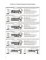
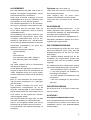
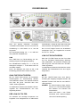
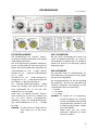
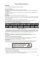
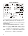
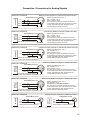
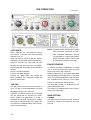
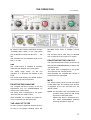
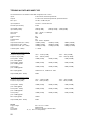
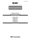
BEDIENUNGSANLEITUNG
USER´s MANUAL
MIC-AMP F355
AVAILABLE MODELS
MIC-AMP F350:
MIC-AMP F355:
1-channel Microphone Preamplifier
(available on request)
2-channel Microphone Preamplifier
Inhalt / Content
Allgemeine Sicherheitshinweise
Das Erde / Masse Konzept
Anschluss / Steckerbelegung
Bedienungsanleitung
Optionen
General Safety Instructions
The Earth / Grounding Concept
Connection / Connectors
User´s Manual
Options
Technische Daten / Technical Specifications
Anhang / Supplement / Jumper Settings
Konformitätserklärung / Conformity Statement
Seite / Page
2
3
4
5
10
11
12
13
14
19
20
21
22
development and Turmstrasse 7a Tel. +49 (0) 7531 73678
manufacturing of 78467 Konstanz Fax +49 (0) 7531 74998
www.lake-people.de
audio electronic GERMANY
1
Allgemeine Sicherheitshinweise
WARNUNG
Bitte lesen Sie die folgenden Sicherheitshinweise:
Wasser, Flüssigkeiten, Feuchtigkeit:
Das Gerät soll nicht in der Nähe von Wasser- oder Flüssigkeitsquellen benutzt werden.
Das Gerät soll nicht in Bereichen grosser Feuchtigkeit betrieben werden.
Achten Sie darauf, dass das Gerät nicht in Flüssigkeiten fällt oder dass Flüssigkeiten durch die
Gehäuseöffnungen eindringen können.
Betriebsspannung:
Das Gerät darf nur mit den in dieser Bedienungsanleitung angegebenen Quellen betrieben werden.
Erdung:
Achten Sie darauf, dass dieses Gerät nur vorschriftsmässig geerdet betrieben wird.
Netzkabel:
Achten Sie auf einen einwandfreien Zustand des Netzkabels.
Verlegen Sie das Netzkabel so, dass es nicht verletzt werden kann und keine Unfallquelle darstellt.
Das Gerät wird mit einem 3-poligen Netzkabel mit deutschem Schuko-Stecker ausgeliefert.
Auf Anfrage wird ein 3-poliges nordamerikanisches Netzkabel mitgeliefert.
In einigen Ländern muss das Gerät mit einem vom Benutzer beigestellten Netzkabel betrieben werden.
Übersicht: Netzkabelfunktionen und Farben
Leiter / CONDUCTOR
E
Farbe
COLOR
Alternativ
Alternativ
L
Phase
LIVE
Braun
BROWN
Schwarz
BLACK
N
Null
NEUTRAL
Blau
BLUE
Weiss
WHITE
Erde
EARTH GND
Grün-Gelb
GREEN+YELLOW
Grün
GREEN
Netzsicherung:
Die Netzsicherung dieses Gerätes ist eingelötet und nur von Innen zugänglich !!
Eine durchgebrannte Sicherung weist auf interne Probleme hin und sollte nur im Rahmen von
qualifizierten Service- oder Reparaturarbeiten ersetzt werden !!
Umschaltbare Stromversorgung / Mehrbereichs-Stromversorgung
Achten Sie auf den im Typenschild angegebenen Bereich der Versorgungsspannung,
um einen sicheren Betrieb zu gewährleisten!!
Dieses Gerät ist entweder mit einer intern umlötbaren Netzspannung 115 / 230 V AC oder
mit einer Mehrbereichsspannung 90 ... 260 V AC ausgerüstet.
Service / Reparatur:
Um das Risiko von Feuer und Stromschlag zu reduzieren, soll dieses Gerät vom Benutzer nicht über die in dieser
Bedienungsanleitung beschriebenen Arbeiten hinaus gewartet oder repariert werden. Überlassen Sie Serviceund Reparaturarbeiten qualifiziertem Personal !!
VOR DEM ÖFFNEN NETZSTECKER
ZIEHEN!! PULL MAINS BEFORE
OPENING!! AVANT D´OUVRIER
RETIREZ LA FICHE MALE!!
Elektromagnetische Verträglichkeit:
Dieses Gerät entspricht internationalen Spezifikationen, die am Ende dieser Bedienungsanleitung in der
KONFORMITÄTSERKLÄRUNG beschrieben sind mit den folgenden Voraussetzungen:
- dieses Gerät strahlt keine störenden Emissionen aus
- dieses Gerät kann in störenden Umgebungen betrieben werden, auch wenn diese den beabsichtigten
Einsatzzweck des Gerätes beeinträchtigen
- der Betrieb dieses Gerätes in Umgebungen mit hohen elektromagnetischen Feldern sollte vermieden werden
2
Das Erde / Masse Konzept
DIGITAL transformer balanced output
XLR male
1
ANALOG transformer balanced output
2
Ground Lift Jumper:
XLR male
2
G(round)
L(ift)
C(ase)
3
100n
3
1
XLR female
DIGITAL transformer balanced input
ANALOG transformer balanced input
2
2
3
DIGITAL unbalanced output
ANALOG electronically balanced output
Ground Lift Jumper:
XLR male
Cinch / RCA
2
DIGITAL unbalanced input
ANALOG electronically balanced input
Cinch / RCA
G(round)
L(ift)
C(ase)
1
100n
3
solid Metal BNC
G(round)
L(ift)
C(ase)
1
3
solid Metal BNC
Ground Lift Jumper:
XLR female
100n
1
Ground Lift Jumper:
XLR female
2
G(round)
L(ift)
C(ase)
1
100n
3
AC Mains
Socket
E
DIGITAL UNITS POWER SUPPLY
ANALOG UNITS POWER SUPPLY
ANALOG unbalanced output
Cinch / RCA
L
N
+18V
AC IN
Multirange
Switchmode
Supply
90 … 260 V AC In
AC IN
5V DC stabilized Supply Voltage
-18V
(others)
stabilized Supply Voltage
Torroidal Transformer
230 / 115 V AC In
ANALOG unbalanced input
100n
10k
Cinch / RCA
GND
Lift
GENERAL GROUND-LIFT JUMPER
Earth / PE to Case
ENCLOSURE
General GROUND-LIFT Jumper (von aussen zugänglich):
Ab Werk ist dieser Jumper auf GND/GROUND gesetzt.
Der interne Masse-Bezugspunkt kann auf der Rückseite des Gerätes über den Jumper von GROUND auf LIFT
gelegt werden. Die Verbindung zwischen internem Masse-Bezugspunkt und Erde wird hierbei für Gleichspannungen und niedrige Frequenzen (< 160 Hz) getrennt. Höherfrequente Störungen werden weiter nach Masse
abgeleitet. Die LIFT-Stellung kann hilfreich sein wenn z.B. aufgrund verschiedener Massepotentiale Brumm oder
Jitter generiert wird.
Leider gibt es keine generelle Empfehlung, wie Brumm- oder Jitterstörungen zu vermeiden oder wenigstens zu
reduzieren sind. Häufig muss probiert werden !! Bei symmetrischen Zuleitungen sollte auch immer überprüft
werden, ob der Schirm Verbindung mit dem Stecker hat. Der Stecker wird IMMER über den 4. Kontakt der XLR
Buchsen auf das Gehäuse-Potential gelegt !!
Wie aus obiger Abbildung ersichtlich, kann das Masse/Erde-Verhältnis der ANALOGEN Ein- und Ausgänge modifiziert werden. Die elektrische Sicherheit immer gewährleistet, da der Schutzleiter PE fest am Gehäuse liegt !!
XLR GROUD-LIFT Jumper (von innen zugänglich, SICHERHEITSHINWEISE beachten !! ):
G(ROUND): Ab Werk sind alle Jumper auf G(ROUND) gesetzt. Pin 1 ist mit dem internen Masse-Bezugspunkt
verbunden. HF Störungen werden über einen 100 nF Kondensator auf das Gehäuse abgeleitet.
Pin 1 ist nicht mit dem internen Masse-Bezugspunkt verbunden. HF Störungen werden über einen
L(IFT):
C(ASE):
100 nF Kondensator auf das Gehäuse abgeleitet. Diese Stellung ist meist nur mit Transformatoren
sinnvoll !!
Pin 1 ist mit dem Gehäuse verbunden, der 100 nF Kondensator ist überbrückt. Diese Jumperstellung kann mir dem General GROUND-LIFT Jumper variiert werden.
Sollte von den Werkseinstellungen abgewichen werden, können EMV Probleme entstehen.
Diese liegen im Verantwortungsbereich des Nutzers !!
3
Anschluss / Steckerbelegung für analoge Signale
ANALOGE SIGNALE
SOURCE
Symmetrisches Kabel (Signal) an (Trafo)symmetrischen Eingang
XLR MALE PLUG
Shield / Abschirmung = Signalmasse = Pin 1
2
1
HOT
3
COLD
SHIELD
X
BALANCED INCOMING SIGNAL
ANALOGE SIGNALE
(Trafo)symmetrischer Ausgang an symmetrisches Kabel
XLR FEMALE PLUG
DESTINATION
Hot / + Phase = Pin 2
Cold / - Phase = Pin 3
Das Steckergehäuse sollte nicht mit der
Abschirmung des Kabels verbunden werden.
Es wird beim Anschluss an das Gerät auf
das Gehäusepotential (PE) gelegt !
2
HOT
1
3
COLD
SHIELD
X
BALANCED OUTGOING SIGNAL
Shield / Abschirmung = Signalmasse = Pin 1
Hot / + Phase = Pin 2
Cold / - Phase = Pin 3
Das Steckergehäuse sollte nicht mit der
Abschirmung des Kabels verbunden werden.
Es wird beim Anschluss an das Gerät auf
das Gehäusepotential (PE) gelegt !
ANALOGE SIGNALE
SOURCE
Unsymmetrisches Kabel (Signal) an (Trafo)symmetrischen Eingang
XLR MALE PLUG
Shield / Abschirmung = Signalmasse = Pin 1
2
HOT
1
3
GND
SHIELD
?
X
BALANCED INCOMING SIGNAL
2-adrige Kabel sind zu bevorzugen !!
ANALOGE SIGNALE
Trafosymmetrischer Ausgang an unsymmetrisches Kabel
DESTINATION
XLR FEMALE PLUG
2
HOT
1
3
GND
SHIELD
Hot / Signal = Pin 2
Cold / Ground = Pin 3
Das Steckergehäuse sollte nicht mit der
Abschirmung des Kabels verbunden werden.
Es wird beim Anschluss an das Gerät auf
das Gehäusepotential (PE) gelegt !
?
X
BALANCED OUTGOING SIGNAL
2-adrige Kabel sind zu bevorzugen !!
Shield / Abschirmung = Signalmasse = Pin 1
Hot / Signal = Pin 2
Cold / Ground = Pin 3
Das Steckergehäuse sollte nicht mit der
Abschirmung des Kabels verbunden werden.
Es wird beim Anschluss an das Gerät auf
das Gehäusepotential (PE) gelegt !
ANALOGE SIGNALE
DESTINATION
Elektronisch symmetrischer Ausgang an unsymmetrisches Kabel
XLR FEMALE PLUG
Shield / Abschirmung = Signalmasse = Pin 1
2
HOT
1
3
GND
SHIELD
BALANCED OUTGOING SIGNAL
2-adrige Kabel sind zu bevorzugen !!
X
Hot / Signal = Pin 2
(Cold) = Pin 3 = unbedingt offen lassen !!
Das Steckergehäuse sollte nicht mit der
Abschirmung des Kabels verbunden werden.
Es wird beim Anschluss an das Gerät auf
das Gehäusepotential (PE) gelegt !
ANALOGE SIGNALE
4
HOT
GND
SHIELD
UNBALANCED INCOMING SIGNAL
DESTINATION
SOURCE
Unysmmetrischer Eingang / Ausgang an unsymmetrisches Kabel
CINCH/BNC PLUG
CINCH/BNC PLUG
HOT
GND
SHIELD
UNBALANCED OUTGOING SIGNAL
ALLGEMEINES
Optionen (siehe auch Seite 10)
Der LAKE PEOPLE MIC-AMP F355 ist ein exzellenter, hervorragend ausgestatteter, extrem
rauscharmer Mikrofon-Vorverstärker.
Durch seine universelle Auslegung und hohe
Pegelfestigkeit ist er auch zum Verstärken oder
Symmetrieren von Line-Signalen geeignet.
Das Verstärkungselement ist in der Grundausführung ein hochwertiger Instrumenten Verstärker. Optional kann der MIC-AMP F355 mit
einem diskret aufgebauten Class-A Frontend
ausgestattet werden.
Die Verstärkung wird für jeden Kanal mit zwei
Bedienelementen vorgenommen: Durch einen
12-stufigen Drehschalter lässt sich die Verstärkung in 6 dB Stufen von 0...+66 dB einstellen. Ein Poti mit Mittelrast erlaubt eine eventuell
erforderliche Feineinstellung mit einem Einstellbereich von +/- 5 dB.
Jeder Kanal verfügt über Taster für
- Phantomspeisung
- Pad
- Phase-Reverse
- (De-) aktivierung der "FINE" -Regelung
- (De-) aktivierung des Lo-Cut Reglers
- Mute
Alle Taster besitzen LED's zur Rückmeldung
des aktivierten Zustands.
Um bei Bedarf den Signalweg so puristisch wie
möglich zu halten, lässt sich die Elektronik der
"FINE" -Regelstufe sowie die "LO-CUT"-Regelstufe per Tastendruck restlos aus der Schaltung
entfernen.
Beim an- oder abschalten der Phantomspeisung können die Ausgänge für ca. 4 Sekunden
gemutet werden.
Eine 16-stufige LED-Kette mit einem semilogarithmischen Anzeigebereich von 36 dB
zeigt den Ausgangspegel an. Die Empfindlichkeit der Anzeige kann über einen Regler auf der
Front einfach an die persönlichen Anforderungen angepasst werden.
Eine Clip-LED blinkt bei Pegeln über +20 dBu
und warnt zuverlässig vor Übersteuerungen.
Die Ein- und Ausgänge befinden sich auf der
Rückseite und sind elektronisch symmetrisch.
Pro Kanal stehen zwei separate Ausgänge zur
Verfügung.
Jeder Kanal kann mit einer Class-A Eingangsstufe ausgerüstet werden.
Jeder Ausgang kann mit einem ActiveFeedback Transformator versehen werden.
Jeder Kanal kann mit einem GP-I/O versehen
werden.
DAS GEHÄUSE
Das geerdete Gehäuse besteht aus 1 - 2 mm
starkem Edelstahl. Dies garantiert eine hohe
mechanische Stabilität und Widerstandsfähigkeit gegen rauhe Umwelteinflüsse.
Durch die hohe elektrische Leitfähigkeit der unbehandelten Oberflächen ergeben sich hervorragenden EMV Eigenschaften.
DIE STROMVERSORGUNG
Die Stromversorgung erfolgt über eine eingebaute IEC-CEE-Dose. Wenn nötig, kann die
Netzspannung intern von 230 auf 115 V umgestellt werden.
Der "POWER"-Schalter befindet sich auf der
Frontplatte. Der eingeschaltete Zustand wird
durch eine LED unter dem "POWER"-Schalter
angezeigt.
Ein überdimensionierter Ringkerntrafo erzeugt
die internen Betriebsspannungen. Es sind dies:
- + 24V ungeregelt für LED´s und Relais
- +/- 18V linear geregelt und stabilisiert für
die analogen Schaltungen
- + 5V linear geregelt und stabilisiert für die
Prozessoren
- + 48V über Schaltregler für die Phantomspannung
DIE NETZSICHERUNG
Die Sicherung 0,25 AT ist intern auf dem Netzteil-Print verlötet.
ACHTUNG !!
SICHERHEITSHINWEISE BEACHTEN:
Eine durchgebrannte Sicherung weist auf interne Probleme hin und sollte nur im Rahmen von
qualifizierten Service- oder Reparaturarbeiten
ersetzt werden !!
5
THEORIE UND PRAXIS
ZUR VERSTÄRKERSTUFE
Die Verstärkung im MIC-AMP F355 erfolgt
durch einen so genannten Instrumenten-Verstärker. Es ist ein für diese Zwecke optimiertes
IC, dass sich durch seine Rauscharmut bei
hohen Verstärkungen und seine hohe Breitbandverstärkung auszeichnet.
Bei einer gewählten Verstärkung von +60 dB
(1000-fach) ergibt sich ein Rauschen, dass
lediglich 1-2 dB über dem theoretisch maximal
erzielbaren Wert liegt.
Die Breitbandverstärkung (GBW = Gain
Bandwidth Product) und die Slew-Rate sind
ursächlich für den Klang eines Verstärkers
verantwortlich. Je höher sie ausfallen, desto
transparenter ist der Klang.
Die Slew-Rate des verwendeten Verstärkers ist
10 V/us, das GBW errechnet sich aus dem
erzielten Frequenzgang bei einer bestimmten
Verstärkung.
Der MIC-AMP F355 hat bei einer Verstärkung
von +60 dB einen internen linearen Frequenzgang von weit über 200 kHz. Daraus ergibt sich
ein theoretisches GBW von 200 MHz (200.000
Hz * 1000).
Optional kann der MIC-AMP F355 mit einer
klassischen Class-A Eingangsstufe ausgerüstet
werden.
Gegenüber der Version mit Instrumenten-Verstärker ergeben sich kleine Nachteile im Bezug
auf den Klirrfaktor bei hohen Eingangssignalen.
Im für einen Mikrofon Vorverstärker relevanten
Bereich von +10 ... +50 dB Verstärkung zeichnet sich die Class-A Version durch einen
geringeren Klirrfaktor aus, bei höheren Eingangspegeln auch durch ein wesentlich geringeres Rauschen.
... wie es klingt ???
Nun, wir bei LAKE-PEOPLE geben uns schon
immer jede erdenkliche Mühe, "Klang" zu vermeiden.
Der Autor dieses Manuals ist der Meinung, das
sich die Standard Version sehr gut für alle
(Standard-) Anwendungen eignet, die Class-A
Version hingegen ist prädestiniert für "Spezielles" Recording !!
6
DER SIGNALWEG UND
DIE BEDIENELEMENTE
DER EINGANG
Der elektronisch symmetrische Eingang befindet sich auf der Rückseite des Gehäuses und
ist mit einer XLR Buchse ausgestattet. Er ist mit
"Input 1" bzw. "Input 2" bezeichnet. Der Eingang akzeptiert symmetrische und unsymmetrische Audiosignale. Die Belegung ist den
internationalen Normen entsprechend
- 1 = Masse
- 2 = (+) Phase
- 3 = (-) Phase
Bei unsymmetrischem Abschluss des Eingangs
sollte Pin 3 auf Masse gelegt werden.
DIE PHANTOMSPEISUNG
Hochwertige Kondensatormikrofone benötigen
im allgemeinen eine Polarisations- oder
Betriebsspannung, die so genannte Phantomspannung.
Der MIC-AMP F355 stellt diese Spannung über
den auf der Front befindlichen "PHANTOM"Taster zur Verfügung. Die aktivierte Funktion
wird durch eine rote LED angezeigt.
Sie beträgt ca. 48 Volt und wird gleichphasig
über 6.8 kOhm Widerstände auf die Pins 2 und
3 der jeweiligen Eingangsbuchse gelegt.
Bei üblichen Mikrofon Vorverstärkern führt das
Ein- und Ausschalten der Phantomspannung
konstruktionsbedingt
zu
niederfrequenten
Spannungsänderungen am Ausgang, die nachfolgendes Equipment beschädigen können.
Deshalb kann im MIC-AMP F355 ein AUTOMute-Vorgang von ca. 4 Sekunden beim Einund Ausschalten der Phantomspeisung programmiert werden.
HINWEIS: Nach
dem
Einschalten
der
Phantomspannung stehen 48 Volt
an den Pins 2 und 3 der jeweiligen
Eingangsbuchse.
Eventuell angeschlossenes LineLevel-Equipment - wie z.B. Synthesizer - kann hierdurch beschädigt
werden.
DIE BEDIENUNG
(1 von 2 Modulen)
AUTO-MUTE
Um die Auto-Mute-Funktion zu kontrollieren
oder zu verändern drücken Sie die Taste
"PHANTOM" und halten sie gedrückt !
Nach zwei Sekunden fängt die "48V"-LED an
zu blinken. Die LED über dem "MUTE"-Taster
zeigt jetzt den Status der Auto-Mute Funktion.
LED an: Auto-Mute aktiv
LED aus: Auto-Mute nicht aktiv
Das betätigen des "MUTE"-Tasters verändert
den Zustand. Durch loslassen der "PHANTOM"-Taste wird der aktuelle Zustand
gespeichert.
DER PAD
Der MIC-AMP F355 akzeptiert am Eingang
Pegel bis +21 dBu. In einigen wenigen Anwendungsfällen kann sich diese sehr hohe
Empfindlichkeit als nicht ausreichend erweisen.
Um das Eingangssignal abzuschwächen, wird
über den auf der Front befindlichen "PAD"Taster ein Spannungsteiler in die Leitung
geschaltet. Er ist auf eine Dämpfung von 12 dB
ausgelegt, womit sich die Eingangsempfindlichkeit auf +33 dBu erhöht.
Der aktivierte Spannungsteiler wird durch eine
rote LED angezeigt.
Die Funktion wird ohne aktive Komponenten im
Signalweg durch ein Relais realisiert.
HINWEIS: Aktivieren Sie den PAD nur dann,
wenn Sie ihn wirklich brauchen. Es
tut keinem Signal gut, unnötig um
12 dB abgeschwächt und dann um
denselben Betrag verstärkt zu
werden.
DIE PHASENUMKEHR
Bei Aufnahmen mit mehreren Mikrofonen kann
der Klangeindruck eventuell bedeutend verbessert werden, wenn die Phasenlage eines oder
mehrerer Mikrofone invertiert wird.
Sei es, weil die Mikrofonaufstellung dies erfordert, oder weil irgendwo ein falsch belegtes
Kabel verwendet wird.
Dies wird durch den "PHASE"-Taster ermöglicht. Er befindet sich auf der Front, die aktivierte Funktion (1800 Phasendrehung) wird
durch eine gelbe LED angezeigt.
Die Funktion wird ohne aktive Komponenten im
Signalweg durch ein Relais realisiert.
DIE VERSTÄRKUNGSEINSTELLUNG
COARSE
Das Eingangssignal gelangt über die rückseitige XLR Buchse auf die extrem rauscharme
Verstärker-Zelle.
7
DIE BEDIENUNG
(1 von 2 Modulen)
Über den präzise rastenden 12-stufigen
"COARSE"-Drehschalter auf der Front wird die
Verstärkung in 6 dB Stufen von 0...+66 dB
eingestellt.
Die Genauigkeit beträgt min. +/- 0,3 dB über
den gesamten Einstellbereich.
auszublenden, verfügt der MIC-AMP F355 über
einen zuschalt- und regelbaren Low-Cut Filter.
Der "LO-CUT"-Regler steuert ein einstellbares
zweipoliges Filter, der Regelbereich erstreckt
sich von 10...250 Hz.
LOW-CUT DE/AKTIVIEREN
FINE
Das "FINE"-Poti zur Feineinstellung der Verstärkung folgt auf die Eingangsschaltung.
Der Einstellbereich beträgt ca. +/- 5 dB, die
strategisch wichtigen +/- 3 dB Punkte sind auf
der Skala markiert.
Durch die Mittelrast des Potis ist die 0 dB
Einstellung jederzeit leicht wieder zu finden.
Über den "FILTER"-Taster auf der Front lässt
sich die komplette Filterschaltung aktivieren
oder deaktivieren. Der aktivierte Zustand wird
über die grüne "ON"-LED über dem "FILTER"Taster signalisiert.
Im deaktivierten Zustand sind sämtliche Schaltungsteile der Filterelektronik aus dem Signalweg entfernt.
GAIN FINE DE/AKTIVIEREN
MUTE
Mit der "FINE"-Taste können die kompletten
Schaltungsteile zur Feineinstellung aktiviert
oder deaktiviert werden. Der aktivierte Zustand
wird über die grüne "ON"-LED über dem
"FINE"-Taster signalisiert.
Im deaktivierten Zustand sind sämtliche Schaltungsteile der Einstell-Elektronik aus dem
Signalweg entfernt.
Mit dem "MUTE"-Taster kann eine Stummschaltung der Ausgänge ausgelöst werden. Die
aktivierte Funktion wird über die rote "MUTE"LED signalisiert.
HINWEIS: Ein Mute-Vorgang erfolgt automatisch für ca. 2 sec beim Einschalten
des Gerätes und während des
Ausschaltens.
Siehe auch Seite 7 zum Thema
Auto-Mute beim aktivieren/deaktivieren der Phantomspeisung.
DER LOW-CUT FILTER
Um störende und unnötige Frequenzen wie
Popplaute und Griffgeräusche an Mikrofonen
8
DIE BEDIENUNG
(1 von 2 Modulen)
DIE PEGELANZEIGE
DIE CLIPANZEIGE
Die Empfindlichkeit der "OUTPUT LEVEL"Anzeige ist individuell kalibrierbar und deshalb
in dBr (relativ) beschriftet.
Die als Kreisausschnitt gestaltete Pegelanzeige aus 16 LEDs wölbt sich über dem Gain-Fine
Regler. Sie ist semilogarithmisch ausgeführt mit
3 dB Abständen von –36 ... –12 dBr, 2 dB Abständen von –12 ... –4 dBr und 1 dB Abständen
von –4 ... 0 dBr.
Der Bereich von –36 ... –8 dBr leuchtet grün,
der Bereich von –6 ... –2 dBr leuchtet gelb und
die LEDs für –1 dBr und 0 dBr sind rot.
Ein Vollwellen-Spitzenwert-Detektor (PPM)
steuert die Anzeige nach DIN-Vorschrift mit
einer Ansprechzeit von <10 ms und einer
Abfallzeit von 1,5 s für 20 dB.
Hinter dem mit "METER ADJUST" bezeichneten Durchbruch auf der Front befindet sich
der mit einem kleinen Schraubenzieher
justierbare Trimmer zur Empfindlichkeitsregelung. Der Einstellbereich ist ca. +6 ... +25 dBu
für 0 dBr.
HINWEIS: Ab Werk ist die rote 0 dBr LED auf
einen Pegel von +15 dBu eingestellt.
Die rote "CLIP"-LED befindet sich rechts vom
"GAIN COARSE"-Drehschalter. Ihr Pegel ist
fest eingestellt, sie beginnt über ca. +20 dBu zu
blinken und warnt so vor drohenden internen
Übersteuerungen.
DIE AUSGÄNGE
Der MIC-AMP F355 ist standardmässig mit
zwei elektronisch symmetrischen XLR Ausgängen pro Kanal ausgestattet.
Die Ausgänge befinden sich auf der Rückseite
des Gehäuses. Sie sind als vergoldete XLR
Verbinder ausgeführt. Die Belegung ist den
internationalen Normen entsprechend
- 1 = Masse
- 2 = (+) Phase
- 3 = (-) Phase
HINWEIS: Es handelt sich um zwangssymmetrierte Ausgänge, d.h. die positive oder die negative Phase darf bei
unsymmetrischem Abschluss nicht
auf Masse gelegt werden sondern
muss offen bleiben.
Weiter stellt sich bei unsymmetrischem Abschluss ein Pegelverlust von 6 dB ein.
9
DIE OPTIONEN
TRAFOSYMMETRSCHE AUSGÄNGE
CLASS A FRONT-END
Optional kann jeder Ausgang des MIC-AMP
F355 mit einem Trafo ausgerüstet werden. Der
verwendete Trafo ist aktiv rückgekoppelt und
erreicht dadurch exzellente dynamische Werte.
Optional kann jeder Kanal des MIC-AMP F355
mit einem Class-A Eingangsverstärker bestückt
werden. Der Umbau sollte ab Werk oder nur
von Fachpersonal vorgenommen werden.
GP-I/O
Diese optionale Schaltung erlaubt, die MuteFunktion des F355 extern auszulösen, oder
über die intern oder extern ausgelöste Mute
Funktion externe Prozesse wie z. B. Rotlicht zu
steuern.
RELAIS
Das Relais wird gesteuert über das /Mute Signal. Im normalen Betrieb ist es aktiv, im MuteFall ist es abgefallen !!
Auf dem Pin 1 des Sub-D 9 Steckers liegt der
"normal offene (NO)" Kontakt des Relais, auf
Pin 2 liegt der "normal geschlossene (NC)"
Kontakt des Relais, auf Pin 6 liegt der Umschalter "Common“.
STROMQUELLE
Über Pin 7 des Sub-D 9 Steckers ist eine
interne Stromquelle zugänglich. Bei einer
Spannung von 24 V +/- 10% kann sie ca. 50
mA liefern. Die Stromquelle ist durch einen PTC
gegen Überlast geschützt.
MASSE
Über Pin 3 ist die interne Masse zugänglich.
10
(ERDE)
Das Gehäuse des Sub-D Steckers ist leitend
mit dem Gehäuse des F355 verbunden, liegt
also auf Schutzerde.
Durch zwei Optokoppler kann über externe Signale ein interner Mute ausgelöst werden.
OPTOKOPPLER 1
Die Lichtquelle des Optokoppler 1 wird intern
versorgt. Über Pin 8 des Sub-D 9 Steckers
kann dieser Optokoppler ein Mute auslösen,
wenn Pin 8 auf Masse gelegt wird.
OPTOKOPPLER 2
Der 2. Optokoppler kann über Pin 4 und Pin 9
erdfrei gesteuert werden.
Ein Mute wird ausgelöst, wenn eine externe
Spannung zwischen Pin 4 (+) und Pin 9 (-)
gelegt wird.
Der eingebaute Vorwiderstand ist für eine externe Spannung von 12 V optimiert !!
General Safety Instructions
WARNING
For your protection, please read the following:
Water, Liquids, Moisture:
This appliance should not be used near water or other sources of liquids.
Care should be taken so that objects do not fall and liquids are not spilled into the enclosure through openings.
Power Sources:
The appliance should be connected to a power supply only of the type described in the operating instructions or
as marked on the appliance.
Grounding:
Care should be taken that this appliance is operated only properly grounded.
Power Cord:
Power supply cords should be routed so that they are not likely to be walked on or pinched by items placed upon
or against them, paying particular attention to cords at plugs, convenience receptacles, and the point where they
exit from the appliance.
This unit is equipped with a 3-pole mains cable with German 3-pin mains plug.
On request this units may be delivered with a 3-pole mains cable with North American 3-pin mains plug.
In some countries this unit must be operated with a mains cable, supplied by the owner.
Please refer to the table below to connect a mains plug:
OVERVIEW: POWER CORD FUNCTION AND COLORS
Leiter / CONDUCTOR
L
N
E
Phase
LIVE
Farbe
COLOR
Alternativ
Alternativ
Braun
BROWN
Schwarz
BLACK
Null
NEUTRAL
Blau
BLUE
Weiss
WHITE
Erde
EARTH GND
Grün-Gelb
GREEN+YELLOW
Grün
GREEN
U.K. Mains Plug Warning:
A moulded mains plug that has been cut off from the cord is unsafe. Discard the mains plug at a suitable disposal facility.
NEVER UNDER ANY CIRCUMSTANCES SHOULD YOU INSERT A DAMAGED OR CUT MAINS PLUG INTO A 13 AMP
POWER SOCKET. Do not use the mains plug without the fuse cover in place. Replacement fuse covers can be obtained from
your local retailer. Replacement fuses are 13 amps and MUST be ASTA approved to BS 1362.
Mains Fuse:
The mains fuse of this appliance is soldered in place and only accessible from the inside !!
A burnt fuse may be an indicator of internal problems and should be replaced during a qualified servicing or
repairing works !!
Switchable Power Supply, Multimode Power Supply:
Connect this unit only to the power source indicated on the equipment rear panel to ensure safe operation !!
This unit is provided with either a internally solderable mains supply of 115 / 230 V AC or
a multimode power supply which covers the range of 90 ... 260 V AC.
Service / Repair:
To reduce the risk of fire or electric shock, the user should not attempt to service the appliance beyond that
described in the operating manual. All other servicing or repair should be referred to qualified personal !!
VOR DEM ÖFFNEN NETZSTECKER
ZIEHEN!! PULL MAINS BEFORE
OPENING!! AVANT D´OUVRIER
RETIREZ LA FICHE MALE!!
Electromagnetic Compatibility
This unit conforms to the Product Specifications noted as Declaration of Conformity at the end of this manual.
Operation is subject to the following conditions:
- this device may not cause harmful interferences
- this device must accept any interference received, including interference that may cause undesired operation
- this device must not be operated within significant electromagnetic field
11
The Earth / Grounding Concept
XLR male
1
DIGITAL transformer balanced output
ANALOG transformer balanced output
2
Ground Lift Jumper:
XLR male
2
G(round)
L(ift)
C(ase)
3
100n
3
1
XLR female
DIGITAL transformer balanced input
ANALOG transformer balanced input
2
2
3
DIGITAL unbalanced output
ANALOG electronically balanced output
Ground Lift Jumper:
XLR male
Cinch / RCA
2
DIGITAL unbalanced input
ANALOG electronically balanced input
Cinch / RCA
G(round)
L(ift)
C(ase)
1
100n
3
solid Metal BNC
G(round)
L(ift)
C(ase)
1
3
solid Metal BNC
Ground Lift Jumper:
XLR female
100n
1
Ground Lift Jumper:
XLR female
2
G(round)
L(ift)
C(ase)
1
100n
3
AC Mains
Socket
E
DIGITAL UNITS POWER SUPPLY
ANALOG UNITS POWER SUPPLY
ANALOG unbalanced output
Cinch / RCA
L
N
+18V
AC IN
Multirange
Switchmode
Supply
90 … 260 V AC In
AC IN
5V DC stabilized Supply Voltage
-18V
(others)
stabilized Supply Voltage
Torroidal Transformer
230 / 115 V AC In
ANALOG unbalanced input
100n
10k
Cinch / RCA
GND
Lift
GENERAL GROUND-LIFT JUMPER
Earth / PE to Case
ENCLOSURE
General GROUND-LIFT Jumper (accesible from the rear of the case):
Ex works this jumper is plugged to GND/GROUND position.
The internal ground potential, which is normally connected to the external earth reference at this point may be
lifted with the aid of this jumper. As a result the interconnection for DC voltages and lower frequencies (< 160 Hz)
will be cut. Higher frequency are allowed to find their way to earth potential through the RC filter. The LIFT
position may be helpfull when e. g. because of different ground/earth potentials hum or jitter is generated.
Unfortunately there is no general recommendation how to solve hum and jitter problems - or even minimize them.
The best way to succeed is to check different options !! In case of balanced cables it should always been verified
if the shield of the cable is connected to the body of the XLR connector. The connector is ALWAYS connected to
Earth potential when plugged in !!
Concerning ANALOG inputs and outputs, the relationship between ground and earth may be modified. In any
case the electrical security is ensured, because the earth conductor is always connected to the enclosure !!
XLR GROUD-LIFT Jumper (accesible from the inside, follow the SECURITY INSTRUCTIONS !! ):
G(ROUND): Ex works all jumpers are set to G(ROUND) position. Pin 1 is connected to the internal ground
reference. High frequency interferences are deflected to the case via a 100 nF capacitor.
The interconnection between Pin 1 and ground is open. High frequency interferences are deflected
L(IFT):
to the case via a 100 nF capacitor. This jumper position is useful when the unit is equipped with
transformers !!
Pin 1 is connected to the case, the 100 nF capacitor is bridged. This jumper position may be varied
C/ASE):
together with the General GROUND-LIFT jumper.
Please note that with jumpers in LIFT or GROUND position EMC problems might occure.
Theses are in the field of the user´s responsibility !!!!
12
Connection / Connectors for Analog Signals
ANALOG SIGNALS
Balanced Cable (Signal) to (Transformer) Balanced Input
2
HOT
1
3
COLD
SHIELD
X
BALANCED INCOMING SIGNAL
ANALOG SIGNALS
(Transformer) Balanced Output to Balanced Cable
DESTINATION
XLR FEMALE PLUG
2
HOT
1
3
COLD
SHIELD
X
BALANCED OUTGOING SIGNAL
ANALOG SIGNALS
SOURCE
2
HOT
1
3
SHIELD
?
X
BALANCED INCOMING SIGNAL
2-wire cable should be prefered !!
ANALOG SIGNALS
DESTINATION
2
HOT
1
3
SHIELD
?
X
BALANCED OUTGOING SIGNAL
2-wire cable should be prefered !!
ANALOG SIGNALS
DESTINATION
Shield = Signal Ground = Pin 1
Hot / Signal = Pin 2
Cold / Ground = Pin 3
The case of the connector should not be wired
to the shield of the cable. The connector is routed
to earth potential (PE) when plugged into the
corresponding socket of the case !
Electronically Balanced Output to Unbalanced Cable
XLR FEMALE PLUG
2
HOT
1
3
GND
SHIELD
BALANCED OUTGOING SIGNAL
2-wire cable should be prefered !!
ANALOG SIGNALS
CINCH/BNC PLUG
SOURCE
Shield = Signal Ground = Pin 1
Hot / Signal = Pin 2
Cold / Ground = Pin 3
The case of the connector should not be wired
to the shield of the cable. The connector is routed
to earth potential (PE) when plugged into the
corresponding socket of the case !
Transformer Balanced Output to Unbalanced Cable
XLR FEMALE PLUG
GND
Shield = Signal Ground = Pin 1
Hot / + Phase = Pin 2
Cold / - Phase = Pin 3
The case of the connector should not be wired
to the shield of the cable. The connector is routed
to earth potential (PE) when plugged into the
corresponding socket of the case !
Unbalanced Cable (Signal) to (Transformer) Balanced Input
XLR MALE PLUG
GND
Shield = Signal Ground = Pin 1
Hot / + Phase = Pin 2
Cold / - Phase = Pin 3
The case of the connector should not be wired
to the shield of the cable. The connector is routed
to earth potential (PE) when plugged into the
corresponding socket of the case !
HOT
GND
SHIELD
UNBALANCED INCOMING SIGNAL
X
Shield = Signal Ground = Pin 1
Hot / Signal = Pin 2
(Cold) = Pin 3 = must be left open !!
The case of the connector should not be wired
to the shield of the cable. The connector is routed
to earth potential (PE) when plugged into the
corresponding socket of the case !
Unbalanced Input / Output to Unbalanced Cable
CINCH/BNC PLUG
DESTINATION
SOURCE
XLR MALE PLUG
HOT
GND
SHIELD
UNBALANCED OUTGOING SIGNAL
13
GENERAL
OPTIONS (see page 19 for more details)
The LAKE PEOPLE MIC-AMP F355 is an
extremely low-noise and fully featured microphone preamplifier with excellent specifications.
Due to its versatile concept and high level
capability it is also suitable for line signal
boosting and balancing.
The gain element of the standard version is a
high quality instrumentation amplifier. As an
option, MIC-AMP F355 may be equipped with
a sophisticated Class-A frontend, built with
discret components.
Gain is controlled with two knobs per channel:
a twelve-step rotary switch sets coarse gain in
6-dB steps from 0 to +66 dB. A centerdetented potentiometer allows fine adjustment
within a range of +/- 5 dB.
The lo-cut filter may be set individually from 10
to 250 Hz.
Each channel is equipped with buttons for
- Phantom powering
- Pad
- Phase reverse
- (de-) activation of Gain-Fine adjust
- (de-) activation of Lo-Cut control
- Mute
The state of all these buttons is reported by
LEDs.
In order to keep the signal path as pure as
possible, the electronic components of the
Gain-Fine control and the Lo-Cut filter stage
may be removed completely with the aid of
relais.
Whilst switching on or off the phantom power,
the outputs may be muted during 4 seconds.
A sixteen-segment LED bargraph with semilogarithmical law displays the output level over
a range of 36 dB. Display sensitivity can be
adjusted to the user's requirements with a trim
located on the front panel.
A clip LED starts flashing at levels above +20
dBu and thus reliably warns against distortion.
The electronically balanced inputs and outputs
are situated on the rear panel.
Each channel is equipped with two outputs.
Each channel may be equipped with a Class-A
input stage.
Each output can be equipped with transformer
balanced outputs consisting of active feedback
transformers.
Each channel may be equipped with a versatile
GP-I/O interface.
14
THE CASE
The grounded case is made of 1 -2 mm thick
stainless steel. This provides high mechanical
stability and resistance against rough handling.
The cases surfaces are not treated with any
material, so providing excellent electrical conductances for optimum EMC characteristics.
THE POWER SUPPLY
Mains is connected via a built-in IEC-CEE
mains socket. If necessary, mains voltage can
be internally altered from 230 to 115 V.
The "POWER"-switch is situated on the front
panel. Power status is displayed by a LED
situated below the power switch.
An oversized toroidal transformer delivers the
internal supply voltages.
These are:
- +24 V unregulated for LED´s and relais
- +/-18 V linear stabilized for the analog
circuitry
- +5 V linear stabilized for the processors
- +48 V via DC/DC converter for phantom
powering
THE MAINS FUSE
The 0,25 AT fuse is internally soldered in place
on the power supply PCB.
ATTENTION !!
FOLLOW THE SAFETY INSTRUCTIONS:
A blown fuse may refer to internal problems
and should only been replaced during qualified
servicing works !!
THE AMPLIFIER STAGE:
THEORY AND PRACTICE
THE SIGNAL PATH AND
THE CONTROLS
The MIC AMP F355's gain is effected by a so
called instrumentation amplifier. It is represented by an IC specially designed for this task,
distinguishing itself by very low noise figures
and a high gain/bandwidth product.
When gain is set to +60 dB (x1000), the
amount of noise added is only 1-2 dB more
than the (theoretically) achievable minimum.
The gain/bandwidth product (GBW) and the
slew rate are basically responsible for the
sonic quality of an amplifier. The higher they
are, the more transparent the sound becomes.
Slew rate is 10V/s, while the GBW is
calculated from the frequency response at a
certain gain ratio.
The MIC AMP F355's internal linear frequency
response at +60 dB gain exceeds 200 kHz.
This results in a theoretical GBW as high as
200 MHz (200.000 Hz x 1000).
As an option MIC-AMP F355 may be equipped
with a Class-A input amplifier. It is the actual
version of circuit designs which can be found in
classic applications.
Compared to the version with integrated instrumentation amplifier there are small disadvantages concerning THD when dealing with high
level input signals. As the relevant operation
range of a microphone preamplifier is a gain
make-up of +10 … +50 dB, here the Class-A
version shows lower THD.
Also, with higher level signals the noise floor is
significantly lower.
THE INPUT
… and how does it sound ???
Well, since the beginning we at LAKE PEOPLE
spend lots of efforts to create no sounding
instruments !!
The author´s opinion is, that the standard
version of MIC-AMP F355 is best suited for all
standard applications.
Whereas the Class-A version is predestinated
for "Special" Recording.
The balanced input is situated on the rear
panel, fitted with XLR type socket. It is denoted "INPUT 1" and "INPUT 2" respectively.
The input accepts balanced as well as
unbalanced audio signals. XLR wiring
corresponds to international standards with
- Pin 1 = ground,
- Pin 2 = + (in phase) and
- Pin 3 = - (out of phase)
If an unbalanced source is connected, one of
the phases (preferably the negative one)
should be connected to signal ground.
PHANTOM POWERING
The use of professional condenser microphones requires in general a polarisation
voltage or operating voltage, the so called
phantom power.
The MIC AMP F355 offers a stabilized 48V
phantom voltage, which is activated by the
"PHANTOM"-button on the front panel.
This voltage is applied to the input pins 2 and 3
via matched 6,8 kOhms resistors.
Active phantom powering is indicated by the
red "48V"-LED.
Normal microphone preamplifiers will produce
low-frequency voltage swing at their outputs
when switching the phantom power on or off.
This may damage subsequent equipment !
Therefore MIC-AMP F355 provides the "AUTO-MUTE"-feature which offers a 4-seconds
output mute whilst switching pantom on or off.
NOTE: If unbalanced equipment such as
synthesizers etc. are connected to the
MIC AMP F355's input, the 48V
phantom voltage might cause damage
if the connection is not made properly.
This problem is faced with all phantom
powered inputs and can be avoided by
using a transformer coupled D.I. box or
by strictly keeping the unbalanced
wiring apart from pin 1 (ground).
15
THE OPERATION
(1 of 2 Modules)
AUTO-MUTE
When engaged, the "AUTO-MUTE"-function
will create a 4 seconds mute whilst switching
phantom on or off.
When you want to check or alter this function
depress the “PHANTOM”-button permanently.
After two seconds the "48V"-LED will start
flashing and the “ON”-LED over the “MUTE”button shows the actual state of the Auto-Mute
function.
LED on: Auto-Mute enabled
LED off: Auto Mute disabled
Pushing the “Mute”-button will change the
state. Releasing the “PANTOM” button will
save the actual state.
THE PAD
The MIC AMP F355's inputs accept levels of
up to +21 dBu. In some applications, this level
capability may still not be sufficient.
Therefore, a resistive network can be inserted
into the signal path by pressing the "PAD"button. Offering an attenuation of 12 dB, it
increases the maximum input level to +33 dBu.
Active pad is indicated by the red “-12dB“-LED.
This function is realized without active components in the signal path.
16
NOTE: The PAD-switch should only be used if
really necessary. Otherwise an eventually redundant attenuation must be
compensated by a higher gain setting,
which practically means nothing else
but decreasing signal-to-noise ratio.
PHASE REVERSE
In multiple microphone applications, inverting
one or several microphones' phase can significantly improve the the overall mix.
Reason therefore may be position-dependent
time lags between microphones or, in the worst
case, an incorrectly soldered microphone lead.
The "PHASE"-button serves to invert signal
polarity. It is situated on the front panel.
The activated function is displayed by the
yellow “REVERSE”-LED.
This function is realized without active components in the signal path.
GAIN SETTING
COARSE
The signal which is input to the XLR socket on
the back is routed to the extremely low noise
gain cell.
THE OPERATION
(1 of 2 Modules)
By means of the precisely detentend 12-steps
“COARSE”-rotary switch on the front panel
gain is adjusted in steps of 6 dB from 0 … +66
dB.
The deviation from the indicated value is less
than +/- 0,3 dB.
FINE
The "FINE"-control is intended to precisely
adjust the gain between two coarse steps.
The setting range covers +/-5 dB. The
important +/- 3 dB points are marked on the
scale.
Due to the center detent, the 'neutral' position
of this control is easy to reproduce.
DE/ACTIVATING GAIN FINE
The complete electronic circuitry of the fine
adjustement may be enabled/disabled by
means of the “FINE”-button.
The active state is displayed by the green
“ON”-LED over the “FINE”-button.
When disabled, the complete fine adjust circuitry is removed from the signal path.
MIC-AMP F355 offers a variable Low-Cut
Filter.
The two-pole lowcut filter may be adjusted
from 10-250 Hz by the "LOW-CUT"-Control.
DE/ACTIVATING THE LOW-CUT
The complete electronic circuitry of the low-cut
filter may be enabled/disabled by means of the
“FILTER”-button.
The active state is displayed by the green
“ON”-LED over the “FILTER”-button.
When disabled, the complete filter-circuitry is
removed from the signal path.
MUTE
The “MUTE”-button serves to mute the outputs
of MIC-AMP F355. The enabled mute function
is displayed by the red “ON”-LED over the
“MUTE”-button.
NOTE: An automatic mute is proceeded for 2
seconds during power-up and during
shut down of MIC-AMP F355.
Please refer also to “Auto-Mute” function whilst enable/disable phantom
powering decribed on page 16.
THE LOW-CUT FILTER
In order to reduce undesired frequencies such
as wind or microphone handling noise, the
17
THE OPERATION
(1 of 2 Modules)
THE LEVEL METER
THE CLIP INDICATOR
The sensitivity of the “OUTPUT LEVEL“-display is individually adjustabel and therefore
indicated in dBr (relative).
The level meter is designed as a sector of a
circle consisting of 16 LEDs vaulting over the
“GAIN FINE”-control.
The display law is semi-logarithmic with 3 dB
gaps between –36 … -12 dBr, 2 dB gaps
between –12 … -4 dBr and 1 dB gaps between
–4 … 0 dBr.
The range from –36 … -8 dB consitst of green
LEDs, while the range from –6 … -2 dBr is
displayed by yellow LEDs. The LEDs for –1
dBr and 0 dBr are red.
The full-wave peak detector (PPM) accurately
controls the display at DIN specifications, with
a rise time of <10 milliseconds and 1,5
seconds release time for a 20 dB level change.
Behind the drilling denoted "METER-ADJUST"
on the front panel, a trimmer accessible with a
small screwdriver is provided for display range
adjustment.
NOTE: The standard factory setting is +15
dBu output level for a 0 dBr display.
The red “CLIP”-LED is situated near to the
“GAIN-COARSE”-control.
It starts flashing at about +20 dBu and thus
reliably warns against internal overload. The
trigger is fixed and may not be altered.
18
THE OUTPUTS
In its standard version, the MIC AMP F355 is
equipped with two electronically balanced
output per channel.
All outputs are equipped with XLR sockets and
situated on the rear panel.
XLR wiring corresponds to international
standards with
- Pin 1 = ground,
- Pin 2 = + (in phase) and
- Pin 3 = - (out of phase).
NOTE: In case of unbalanced termination
neither the positiv nor the negative
phase may be tied to ground. To
prevent unwanted distortion, the not
used output pin should remain open.
In case of unbalanced termination the
output level is reduced by 6 dB !
THE OPTIONS
TRANSFORMER BALANCED OUTs
CLASS-A FRONT END
As an option each output may be equipped
with high quality output transformers. These
transformers are controlled by a special
circuitry to achieve low inner resistance, very
good frequency range and low distortions.
They exceed IRT recommendations.
As an option, each channel of MIC-AMP F355
may be equipped with a class-A input amplifier.
This option should only be installed ex works
or by trained professionals.
GP-I/O
This optional circuitry serves to externally
actuate the mute function of F355 or to control
external processes like “Rec-Light” by
internally or externally released mutes.
RELAIS
The relais is controlled by the internal /Mute
signal. During normal operation it is active,
under mute conditions it is released !!
Pin 1 of the Sub-D 9 connector is wired to the
NO (normally open) contact of the relais.
Pin 2 of the Sub-D 9 connector is wired to the
NC (normally closed) contact of the relais.
Pin 6 of the Sub-D 9 connector is wired to the
Common contact of the relais.
CURRENT SOURCE
Pin 7 of the Sub-D 9 connector is wired to an
internal current source. It delivers approx. 50
mA with a voltage of 24 V +/- 10%.
The current source is protected against
overload by means of a PTC.
GROUND
Via Pin 3 the internal ground is accessible.
(PROTECTIVE EARTH)
The case of the Sub-D connector is screwed to
the case of F355 and therefore connected to
protective earth.
With the aid of two optocouplers an internal
mute may be released by external signals.
OPTOCOUPLER 1
This optocoupler is supplied internally.
If Pin 8 from the Sub-D 9 connector is wired to
ground this will release a mute.
OPTOCOUPLER 2
This optocoupler may be controlled via Pin 4
and Pin 9 of the Sub-D 9 connector totally
floating.
A mute is released when an external voltage is
connected to Pin 4 (+) and Pin 9 (-).
The built-in resistor is optimized for 12 V
external.
19
TECHNICAL DATA MIC-AMP F355
All measurements as not otherwise noted: RMS unweighted, 20 Hz - 20 kHz
Inputs:
Outputs:
2 x XLR female, electronically balanced
2 x 2 XLR male, electronically balanced, optional transformer
Max. Input:
+21 dBu, +33 dBu with pad
Input Impedance:
>2 kohms / >5 kohms with Pad
Nominal input sensitivity:
+6 dBu
Input CMRR (100Hz):
Input CMRR (15kHz):
>78dB (A=0dB),
>57dB (A=0dB),
Gain Coarse:
Gain Fine:
0 dB … +66 dB, 11 x 6dB steps
-5dB…+5dB
Phantom Voltage:
Pad:
Phase Reverse:
Lo-Cut:
48V
12dB
180°
12Hz…250Hz adjustable
Output Noise unwtd. (Rin = 200R) :
Output Noise ‘A’ (Rin = 200R) :
Output Noise ‘CCIR ’ (Rin = 200R) :
<-94dBU (A=0dB),
<-96dBU (A=0dB),
<-83dBqp (A=0dB),
Crosstalk (20Hz…20kHz):
<< -100dB
>78dB (A=42dB),
>87dB (A=42dB),
>78dB (A=60dB)
>84dB (A=60dB)
<-84dBU (A=42dB),
<-86dBU (A=42dB),
<-72dBqp (A=42dB)
<-68dBU (A=60dB)
<-70dBU (A=60dB)
<-56dBqp (A=60dB)
A) Electronically balanced Outputs:
Frequency range (-0.5dB):
Frequency range (-3dB):
10Hz ... 61kHz (A=0dB),
<5Hz … 165kHz (A=0dB),
12Hz ... 40kHz (A=60dB)
<5Hz … 106kHz (A=60dB)
Thd+N (20Hz…20kHz):
pout = 6dBU @600R
<-98dB (A=0dB),
<-89dB (A=42dB),
<-73dB (A=60dB)
Thd+N (20Hz…20kHz):
pout = 20dBU @600R
<-96dB (A=0dB),
<-96dB (A=42dB),
<-84dB (A=60dB)
Thd+N (1kHz):
pout = 20dBU @600R
<-99dB (A=0dB),
<-99dB (A=42dB),
<-88dB (A=60dB)
Max. Output @600R:
+23dBU Fine off, +26dBU Fine: +5dB
Output CMRR (20Hz…20kHz):
>80dB
B) Transformer balanced Outputs:
Frequency range (-0.5dB):
Frequency range (-3dB):
10Hz ... 30kHz (A=0dB),
<5Hz … 80kHz (A=0dB),
Thd+N (40Hz…20kHz):
pout = 6dBU @600R
<-96dB (A=0dB),
<-89dB (A=42dB),
<-73dB (A=60dB)
Thd+N (40Hz…20kHz):
pout = 20dBU @600R
<-90dB (A=0dB),
<-90dB (A=42dB),
<-83dB (A=60dB)
Thd+N (1kHz):
pout = 20dBU @600R
<-98dB (A=0dB),
<-98dB (A=42dB),
<-87dB (A=60dB)
Max. Output @600R:
+22dBU
Output CMRR (20Hz…20kHz):
>60dB
General
Supply Voltage:
Case:
Front / Back:
Dimensions:
20
230 / 115 V AC / 15 Watt
Stainless Steel
Aluminium, dark grey / Stainless Steel
19“, 1U, 483 x 44 x 166 (WxHxD)
12Hz ... 25kHz (A=60dB)
<5Hz … 68kHz (A=60dB)
PCB LAYOUT AND JUMPER SETTING
MIC-AMP F355
C-L-G
Pin 1 from XLR socket
connected to internal
Ground-Plane..
(ex Works setting)
C-L-G
Pin 1 from XLR socket
lifted.
C-L-G
Pin 1 from XLR socket
connected to case.
GP-I/O
OPTION
Peak-Meter
sensitivity adjustment
Approx. +6 … +25 dBu
for 0 dBr LED
Ex Works adjusted to
+15 dBu for 0 dBr LED
21
KONFORMITÄTSERKLÄRUNG
CONFORMITY STATEMENT
Wir bestätigen hiermit, dass das folgende Gerät:
We herewith declare that the following unit:
Bezeichnung:
Name :
MIC-AMP F355
Serien Nr. :
-alle -
MIC-AMP F355
Serial No:
- all -
mit folgenden EU-Richtlinien bzw. Normen
übereinstimmt:
is in conformity with the following EC directives:
73/23/ EWG neu 93/68/EWG;
Niederspannungsrichtlinie
73/23/ EEC new 93/68/ EEC;
Low voltage directive
89/336/EWG;
Elektromagnetische Verträglichkeit
89/336/EEC;
Electromagnetic compability
Zur Beurteilung des Erzeugnisses hinsichtlich seiner
elektromagnetischen Verträglichkeit wurden
folgende, harmonisierten Vorschriften angewendet:
For verification of conformity with regard to
electromagnetic compability the following
harmonized standards are applied:
EN 50081-1 / 1992
Fachgrundnorm Störaussendung
EN 50081-1 / 1992
Generic emission standard
EN 50082-1 / 1997
Fachgrundnorm Störfestigkeit
EN 50082-1 / 1997
Generic immunity standard
Produktfamiliennorm für Audio- Video- und
audiovisuelle Einrichtungen sowie für StudioLichtsteuereinrichtungen für professionellen Einsatz:
Product family standard for audio, video, audio-visual
and entertainment lightning control apparatus for
professional use:
EN 55103-1 / 1997
EN 55103-2 / 1997
Teil 1: Störaussendung
Teil 2: Störfestigkeit
Für diese Erklärung ist der Hersteller verantwortlich:
EN 55103-1 / 1997
EN 55103-2 / 1997
Part 1: Emission
Part 2: Immunity
This declaration is given under responsibility of:
Lake People electronic GmbH
Turmstrasse 7a, D-78467 Konstanz
----------------------------------------------------------------------------Konstanz 15.06.2005, Fried Reim, Geschäftsführer / CEO
22
development and Turmstrasse 7a Tel. +49 (0) 7531 73678
manufacturing of 78467 Konstanz Fax +49 (0) 7531 74998
www.lake-people.de
audio electronic GERMANY