1
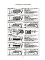
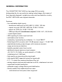
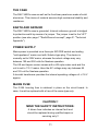
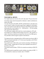
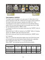
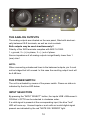
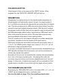
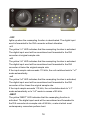
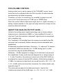
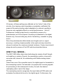
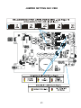
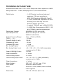
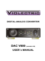
DIGITAL-ANALOG CONVERTER
DAC V800 (version 2.0)
USER´s MANUAL
1
Content
Theme
Page
About Violectric
Safety Instructions
The Earth / Grounding Concept
Connection / Connectors
General
Operation
Things to know
Dismantling / Jumper Setting
Technical Data
Conformity Statement
Warranty
2
3
5
7
9
10
11
18
20
22
23
24
Cordial thanks for your decision in favour of a
product !
is a trademark and product line of Lake People
electronic GmbH. Lake People electronic GmbH develops,
manufactures and distributes products in the professional range, for
broadcast, television, airports, exhibition halls, festival venues, theatres,
large-scale installations, private studios and more. In the private sector
as well, Lake People products become increasingly popular due to their
outstanding quality.
The
trademark and product line is specially intended to
supply the Hi-Fi and High-End market with its specific requirements.
Who develops
equipment ?
devices are exclusively developed in Germany by the
engineers of Lake People electronic GmbH. In doing so, the team of
developers can draw on twenty years of experience and countless
products for the pro-audio domain.
Among others, the first German-made 20-bit A/D and D/A converters
were developed by Lake People in the early nineties of the past century.
Who manufactures
equipment ?
devices are exclusively manufactured in Germany by
Lake People electronic GmbH or contractors in the company's vicinity.
- put high emphasis
Lake People - and by association
on domestic manufacturing. As well, all component suppliers are chosen
in order achieve the main part of added value inland.
3
How do
devices get to the customer ?
devices can be obtained from respective specialist
suppliers. If there is none such accessible regionally, the customer is
supported by transregional distribution partners (google may help...)
and, of course, by Lake People electronic GmbH themselves.
… and if it doesn't work like it should ?
devices are covered by a 24-month warranty. In case of
any malfunction during this period, they can be shipped to the
manufacturer directly. Of course, the client will benefit from
's and Lake People's full technical support even when
warranty has expired. Any technical questions or need for advice is
welcome.
is a subsidiary of
LAKE PEOPLE electronic GmbH
Turmstrasse 7a
D-78467 Konstanz
Fon +49 (0) 7531 73678
Fax +49 (0) 7531 74998
www.violectric.de
www.lake-people.de
www.violectric.com
www.lake-people.com
4
General Safety Instructions
WARNING
For your protection, please read the following:
Water, Liquids, Moisture:
This appliance should not be used near water or other sources of liquids.
Care should be taken so that objects do not fall and liquids are not spilled into
the enclosure through openings.
Power Sources:
The appliance should be connected to a power supply only of the type described
in the operating instructions or as marked on the appliance.
Grounding:
Care should be taken that this appliance is operated with proper grounding only.
Power Cord:
Power supply cords should be routed so that they are not likely to be walked on
or pinched by items placed upon or against them, paying particular attention to
cords at plugs, convenience receptacles, and the point where they exit from the
appliance.
This unit is equipped with a 3-pole mains cable with German 3-pin mains plug.
In some countries this unit must be operated with a mains adaptor, supplied by
the owner.
Please refer to the table below to connect a mains plug:
OVERVIEW: POWER CORD FUNCTION AND COLORS
CONDUCTOR
L
N
E
LIVE
COLOR
Alternativ
BROWN
BLACK
NEUTRAL
BLUE
WHITE
PROTECTIVE EARTH
GREEN+YELLOW
GREEN
U.K. Mains Plug Warning:
A moulded mains plug that has been cut off from the cord is unsafe. Discard the mains
plug at a suitable disposal facility.
NEVER UNDER ANY CIRCUMSTANCES SHOULD YOU INSERT A DAMAGED OR
CUT MAINS PLUG INTO A 13 AMP POWER SOCKET. Do not use the mains plug
without the fuse cover in place. Replacement fuse covers can be obtained from your local
retailer. Replacement fuses are 13 amps and MUST be ASTA approved to BS 1362.
5
Mains Fuse:
The mains fuse of this appliance is soldered in place and accessible from the
inside only!!
A blown fuse may indicate an internal problem and should be replaced during
qualified servicing or repair work !!
Switchable Power Supply:
Connect this unit to the power source indicated on the equipment rear panel
only to ensure safe operation !!
This unit is provided with an internally settable mains supply for 115 / 230 V AC.
Service / Repair:
To reduce the risk of fire or electric shock, the user should not attempt to service the
appliance beyond the measures described in the operating manual. All other
servicing or repair should be referred to qualified personnel !!
VOR DEM ÖFFNEN NETZSTECKER
ZIEHEN!! PULL MAINS BEFORE
OPENING!! AVANT D´OUVRIER
RETIREZ LA FICHE MALE!!
Electromagnetic Compatibility
This unit conforms to the Product Specifications noted as Declaration of
Conformity at the end of this manual. Operation is subject to the following
conditions:
-
this device may not cause harmful interferences
this device must accept any interference received,
including interference that may cause undesired operation
this device must not be operated within significant electromagnetic field
6
The Earth / Grounding Concept
General GROUND-LIFT Jumper (accessible from the inside.
Mind the SECURITY INSTRUCTIONS !! ):
Ex-works this jumper is set to the LIFT position.
The internal ground potential is “lifted” by means of this jumper.
As a result, the interconnection for DC voltages and lower frequencies
(< 150 Hz) will be cut. Higher frequencies will be bled off to earth
potential through the RC filter. The LIFT position is helpful in case of
hum or jitter caused by different ground/earth potentials.
Of coarse full electrical protection is garanteed as the case is always
connected to ground/earth potential !
7
Unfortunately there is no general recommendation how to solve hum
and jitter problems - or even minimize them. The best way to succeed is
to check different options !! In case of balanced cables, it should always
been verified if the shield of the cable is connected to the shell of the
XLR connector. The shell is ALWAYS connected to earth potential when
the connector is inserted !!
Concerning ANALOG inputs and outputs, the relationship between
ground and earth may be modified. Electrical safety is always ensured,
since the earth conductor is permanently connected to the enclosure !!
Please note that with jumpers in LIFT or GROUND position
EMC emission might occur,
for which the user is responsible only !
8
Connection / Connectors
9
GENERAL INFORMATION
The VIOLECTRIC DAC V800 is a top-range D/A converter,
distinguished by its very particular analog output stages. By means of
their specially designed, variable low-noise and low-distortion circuitry,
the DAC V800 fulfils even highest demands.
Features:
- four switchable digital inputs:
- transformer balanced via XLR (AES 3), 24 Bit / 192 kHz
- coaxial via cinch (S/P-DIF, AES-3id), 24 Bit / 192 kHz
- optical via TOS-Link, 24 Bit / 192 kHz
- USB input Style B, transformer-coupled, 24 Bit / 44.1, 48, 96 kHz
- coaxial digital output
- LED signaling for active input and lock
- switchable mute function
- resampling / upsampling by multipliers 1, 2, 4 and "BEST"
- Delta-Sigma D/A converter with 120 dB dynamic range / -112 dB THD
- sophisticated analog output stages, with maximum dynamic
range and minimum distortion
- digitally operated output level control
- additional internal maximum-level jumpers:
+24 /18 /15 /12 /6 dBu, ex works preset to +15 dBu
(unbalanced out: 9 dB less)
- high-quality op-amps along the signal path
- high-quality MKP capacitors along the signal path
- 0,1 / 1 % metal film resistors throughout the unit
- analog outputs electronically balanced via XLR, unbalanced via cinch
- supersized toroidal transformer
- elaborate supply voltage filtering and stabilization
- Nextel-coated, thick-walled aluminum case
- solid aluminum front panel, laser-engraved
10
THE CASE
The DAC V800's case as well as the front/rear panels are made of solid
aluminium. This choice of material ensures high mechanical stability and
resistance.
EARTH AND GROUND
The DAC V800's case is grounded. Internal reference ground is bridged
to protective earth by means of a jumper. The jumper is set to the 'LIFT'
position (see also: page 7 "Earth/Ground concept", page 21 "Technical
Appendix").
POWER SUPPLY
Mains power is provided via a three-pin IEC/CEE socket and mating
"cold-appliance" mains cord with Schuko-type plug. The device is
normally set to 230V mains, whereas the actual voltage may vary
between 190 and 250 volts for flawless operation.
The US and Japan version comes with a US style mains cord and the
unit is set to 115 V mains. Here the AC voltage may vary between 85
and 125 volt for flawless operation.
A toroidal transformer provides the internal operating voltages of +/-18 V
approx.
MAINS FUSE
The 0.25A time-lag fuse is soldered in place on the circuit board. In
case, it must be replaced with a fuse of the same type only.
CAUTION !!
MIND THE SAFETY INSTRUCTIONS:
A blown fuse indicates an internal fault and
should be replaced during qualified repair or
servicing only !!
11
THE DIGITAL INPUTS
Four digital inputs are found on the unit's rear panel. They are denoted
according to their electrical properties: balanced, coaxial (unbalanced),
optical and USB.
You won't find terms like AES, S/P-DIF, professional or consumer here,
since it doesn't matter at all which signal type is applied to a dedicated
input. The electrical inputs (Bal and Coax) accept PCM-encoded digital
audio data with a word length of 16 ... 24 Bit and 28 ... 210 kHz sample
rate. So does the optical input.
The USB input accepts audio data from a host (notebook or PC) with
word length up to 24 Bit and fixed sample rate of 44.1, 48 or 96 kHz. In
order to avoid any interference caused from the host, the USB input is
fully insulated, with the signal coupled via transformer.
The balanced input is equipped with an XLR socket according to AES 31992, transformer-balanced, at 110 ohms input impedance and 200mV
sensitivity at Tnom/2.
The coaxial input is fitted with a cinch socket according to IEC 958 and
AES-3-id resp., unbalanced at 75 ohms input impedance and 200 mV
sensitivity at Tnom/2
The optical input provides a TOS-Link connector according to EIAJ RC5720.
The USB terminal is specified as audio interface according to USB 1.1 /
2.0 standard for a maximum transfer rate of 12 Mbit/S.
12
THE DIGITAL OUTPUT
The digital output is located on the rear panel. It is fitted with a Cinch
socket according to IEC 958, unbalanced at 75 ohms output impedance.
The level at this output however complies with AES-3-id (1 Vss).
The data word on this output is the same as on the selected input by
default. But the output data may also be processed nearly free of jitter
by the resampling module in “BEST”-mode.
To change the mode from the digital output press the “MODE” button for
about 2 sec.
Now either the “x1” LED is lit (default) or the “BEST” LED is lit. Pushing
shortly the “MODE” button will change the status.
Store your entries and leave the menu by pushing the “MODE” button
for 2 seconds.
When “x1” mode was selected the digital output word will be the same
as the digital input word with identical same sample-rate, regardless
which resampling mode (OFF, x1, x2, x4) was selected.
When “BEST” was selected there are the following varieties:
Internal and Output Sample-Rate at selected Resampling:
Input SampleRate (kHz)
OFF
1x
2x
4x
BEST
28 - 55 kHz
follows input
48kHz
96kHz
192kHz
96kHz
55 - 110 kHz
follows input
96kHz
192kHz
x
96kHz
110 - 210 kHz
follows input
192kHz
x
x
96kHz
13
THE ANALOG OUTPUTS
The analog outputs are situated on the rear panel, fitted with electronically balanced XLR terminals, as well as cinch sockets.
Both outputs may be used simultaneously !!
Polarity of the XLR terminals complies with AES 14-1992:
1 = ground, 2 = (+) in phase, 3 = (-) out of phase.
Source impedance of all analog outputs is significantly lower than 1
(one) ohm !
NOTE:
When connecting unbalanced lines to the balanced outputs, pin 3 must
not be bridged but left unused. In this case the resulting output level will
be 6 dB less.
THE POWER SWITCH
The unit is activated by means of the power switch. Power-on status is
indicated by the blue LED below.
INPUT SELECTION
By pressing the “INPUT SELECT“ button, the inputs USB > BALanced >
COAXial > OPTO can be selected in clockwise order.
If a valid signal is present at the corresponding input, the blue "lock"
LED will come up. Unused inputs or such with an invalid digital signal
present are indicated by the red “MUTE ON / ERROR“ light.
14
THE MUTE BUTTON
Output signal is fully cut by means of the “MUTE“ button. When
engaged, the red “MUTE ON / ERROR“ LED will light up.
RESAMPLING
Resampling is a mighty feature for the transformation/restoration of
jittered signals into high-quality signals. As well, the signal quality of
44.1 or 48 kHz sources can be improved by converting them to a higher
rate. This also complies to the USB input which often suffers from jitter
caused by improper treated computer outputs. With the aid of resampling process nearly all jitter (and not only specific ones) is removed from
the USB data stream without using “asynchronous USB mode” which
often is the cause for the next issues. We know that computers are
solving problems which haven’t been existing before.
This isn't mystery at all, but a feature offered by so-called sample rate
converters - available since the nineties of the past century.
While early sample rate converters could provide conversion ratios of
1:2 to 2:1 (at 100dB dynamic range) only, ratios of 1:16 to 16:1 at 140
dB dynamic range are feasible today.
In principle, the digital data stream is asynchronously disassembled by a
DSP specially developed for this purpose, and can be recombined at
virtually any sample rate desired.
By means of this process, all potential jitter vanishes almost completely
and - due to the higher sampling rate - the analog filters after the
converter stage can follow a much more straightforward and "musical"
design. Furthermore, all digital input signals will be completed to 24 bit
signals what is valuable in conjunction with the digital volume control.
THE RESAMPLING BUTTON
By pressing the “RESAMPLING“ button, the modes OFF > x1 > x2 > x4
> BEST can be stepped through in clockwise order.
See also the table on page 13 for the resulting sample-rates.
15
- OFF
lights up when the resampling function is deactivated. The digital input
word is forwarded to the D/A converter without alteration.
- x1
The yellow “x1“ LED indicates that the resampling function is activated.
The digital input word will be recombined and forwarded to the D/A
converter at original sample rate.
- x2
The yellow “x2“ LED indicates that the resampling function is activated.
The digital input word will be recombined and forwarded to the D/A
converter at twice the original sample rate.
If the input sample rate exceeds 110 kHz, the unit switches back to "x1"
mode automatically.
- x4
The yellow "x4" LED indicates that the resampling function is activated,
The digital input word will be recombined and forwarded to the D/A
converter at four times the original sample rate.
If the input sample exceeds 110 kHz, the unit switches back to "x1"
mode automatically or to "x2" mode in excess of 55 kHz.
- BEST
The yellow “BEST“ LED indicates that the resampling function is
activated. The digital input word will be recombined and forwarded to
the D/A converter at a sample rate of 96 kHz, a rate at which most
contemporary converters perform best.
16
THE VOLUME CONTROL
Analog output level is set by means of the "VOLUME“ control. Level
control as such is effected within the D/A converter for both channels
simultaneously by digital processing.
Therefore, no noise, no scratching, no crosstalk or gang errors can
occur at all. Control accuracy is 0.5 dB over a 120dB range.
Since the control affects data word length (and so: signal accuracy), a
setting closest possible to the right end stop should be chosen for the
maximum desired loudness.
ABOUT THE ANALOG OUTPUT LEVEL ...
Unlike in the analog world, digital technology uses a clearly defined
maximum level, described as 0dBFs, or "zero deciBels Full scale" in
clear text. From this maximum downward, signal levels are expressed
with a negative sign.
The “translation“ of the digital level into analog is provided by the D/A
converter and is extremely flexible, whereby several standards have
established.
Professional broadcast facilities in Germany - i.e. radio and TV stations understand 0 dBFs as equivalent to +15 dBu analog level. In other
countries this may be handled differently.
Notabene, +15 dBu represent a voltage of 4.5 Veff which may exceed
the capabilities of many audio devices designed for a voltage swing of
1...2 volts. Therefore, the maximum output level of the DAC V800 can
be adapted by means of internal DIP switches. While factory-preset to
+15dBu, the maximum output level can as well be set to +24 / +18 / +15
/ +12 / +6 dBu (with level knob fully clockwise). For further details, see
appendix page 21.
The values above apply to the balanced outputs. Level at the
unbalanced outputs will be 9 dB lower, i.e. +15 / +9 / +6 / +3 / -3 dB.
17
Of course, all these settings are effected on the "active" side of the
circuitry, thus leaving output impedance completely unaffected. By
means of the active analog output adaptation to external conditions,
there are only negligible effects on overall performance... if at all !
Furthermore, analog output level is controlled by means of a
potentiometer on the front panel. Its setting is translated in the digital
domain only, thus excluding any kind of scratching, crosstalk or gang
errors.
Since the potentiometer affects data word length (and so: signal
accuracy), a setting closest possible to the right end stop should be
chosen to achieve the maximum desired loudness. Coarse level should
always be set by means of the DIP switches described above.
HOW IT ALL WORKS...
The DAC V800 offers high-class technology by means of well thoughout handling, a variety of inputs, the resampling module, a top-notch
converter and, above all, its outstanding and flexible analog output
circuitry.
Taken from one of four possible inputs, the digital signal is forwarded to
the resampling module. Its business is to prepare the incoming signals
for processing in the subsequent circuitry. As well, the desired
resampling ratio is set at this stage.
The resampling module recognizes the input data as PCM audio and
evaluates the status bits found in the digital signal. Furthermore, the
18
resampling module generates auxiliary clock signals needed for further
processing of the digital signal within the unit.
After the resampling stage, an AES/EBU- (or S/P-DIF-) encoded PCM
signal is sent to the rear digital output, while the data contents and
auxiliary clocks are fed to the digital-to-analog converter.
The D/A converter comprises a digital filter, the volume control, the
stereophonic converter as such, as well as the analog output filters. It is
based on a delta-sigma architecture and provides a dynamic range of
127 dB and 64-...128-times oversampling.
The internal frequency of the digital signal (and potential interference
therein) is very high in comparison with the useful analog frequencies.
Therefore, the subsequent analog low-pass filters have to meet less
severe requirements in terms of high-frequency roll-off and can
therefore be realized as "musical", discrete two-pole filters.
Without careful consideration of the analog output stages it wouldn't
have been possible to make the outstanding performance of the topnotch converter available at the analog outputs.
In case of the DAC V800, the converter is followed by an amplifier
specially designed for this purpose, with a topology similar to an
instrumentation amplifier.
It distinguishes itself by a wide dynamic range, minimum distortion and
high flexibility with regard to the achievable output level.
Within this amplifier, the output currents of the D/A converter are
transformed into voltages, while any interferences and processing
frequencies are completely removed.
Gain - i.e. output level – can be set by means of DIP switches over a
very wide range. Fine gain control is provided by trimmers. An error
amplifier caters for minimum DC offset.
Only now follows the output driver stage, feeding the output signal to the
corresponding terminals at extremely low impedance.
The balanced and unbalanced outputs can be used at the same time,
since they are buffered individually. Output impedance for all outputs is
significantly lower than 1 ohm.
19
DISMANTLING / JUMPER SETTINGs
Hint:
Here we are talking about internal adjustments inside your HPA V181.
You are in need of two screw drivers TORX style size T8 and T10.
You should by all means
PULL THE MAINS PLUG !!!
Only thereafter the settings can be altered without any hazard.
DISMANTLING
As the 4-pin XLR socket is fixed to the back side of the front panel,
the front panel may NOT be disassembled !!
To avoid damages please follow the instruction below:
1. screw off both upper screws on the front panel
2. screw off both upper screws on the back panel.
3. unscrew ALL remaining screws on the back panel by 1/10 “ (2-3 mm)
4. now lift the upper lid
5. make your personal jumper settings
5. assemble the unit in reverse order
20
JUMPER SETTING DAC V800
21
TECHNICAL DATA DAC V800
All Measurement RMS unwtd., 20 Hz - 20 kHz, Sample-rate 48 kHz, digital level = 0 dBFs,
analog output level = +15 dBu, Resampling set to x1, as not otherwise noted
Digital Inputs:
Digital Input Formats:
Input Sample Rates:
Analog Frequency Range :
THD (k2 … k10):
Dynamic Range (A-wtd):
Crosstalk (@ 1 kHz):
Crosstalk (@15 kHz):
Bal. Analog Outputs:
Bal. Analog Output Level:
Output CMRR(@ 15 kHz):
Output Impedance:
Unbal. Analog Outputs:
Unbal. Analog Output Level:
Output Impedance:
Mains Voltage :
Case , Back:
Front:
Dimensions:
- 1 x XLR female, transformer balanced,
impedance 110 ohms according to
AES3-1992, Sensitivity 200mV @ Tnom/2
- 1 x Cinch, unbalanced, impedance 75 ohms
according to IEC 958 resp. AES-3-id
Sensitivity 200mV @ Tnom/2
- 1 x optical, TOS-Link, acc. to EIAJ RC-5720
- 1 x USB, Style B, according to USB 1.1 / 2.0
up to 12 Mbit/s, transformer decoupled
AES/EBU, S/P-DIF up to 24 Bit
Bal & Coax & Opto 28 - 210 kHz
USB 44.1, 48, 96 kHz
4 Hz ... 53 kHz (-0,5 dB)
-112 dBu
122 dB
-125 dB
- 110 dB
2 x XLR male
+24 / +18 / +15 / +12 / +6 dBu (selectable)
ex works set to +15 dBu,
> 60 dB
< 1 ohms
2 x Cinch
+15 / +9 / +6 / +3 / -3 dBu (selectable)
ex works set to +6 dBu,
< 1 ohms
230 V AC / 115 VAC max. 10 VA
Aluminium, Nextel coated
Aluminium, milled, sanded, black anodized,
laser engraved
170 x 49 x 226 mm (B x H x D)
22
EU CONFORMITY STATEMENT:
We herewith declare that the following unit
Name:
VIOLECTRIC DAC V800
Serial No. :
-alle -
is in conformity with the following EC directives:
2006/95 EG
2004/108 EG
EN 60065 : 2002
Low voltage directive
Electromagnetic compability
Security directives for audio-,
video- und similar electronic devices
For verification of conformity with regard to electromagnetic compatibility the
following harmonized standards are applied:
EN 50081-1 : 1992
EN 50082-1 : 1992
Generic emission standard
Generic immunity standard
Product family standard for audio, video, audio-visual entertainment apparatus:
EN 55013 : 2001
EN 55020 : 2002
EN 61000-3-2 : 2000
EN 61000-3-3 : 1995
This declaration is given under responsibility of:
LAKE PEOPLE electronic GmbH
Turmstrasse 7a
D-78467 Konstanz
Fon +49 (0) 7531 73678
Fax +49 (0) 7531 74998
Konstanz 01.05.2010
Fried Reim
23
CEO
WARRANTY
Since 1986 we are constructing and manufacturing sophisticated
electronics for ambitious customers.
Since the early beginnings we are trying hard by accompanying
measures, the use of 1st choice components and multiple quality
checks during production to avoid faults at large.
We are quite effective in that and this is – amongst others - why we
enjoy such a good reputation.
Despite all accurateness faults may occure which may derogate the
proper operation of your product.
In this case your unit is protected by a 2-year Warranty !
Needless to say that we will care for your product even after the
expiration of the warranty. If it is necessary please dispatch your item to:
Lake People electronic GmbH
Turmstrasse 7a
D-78467 Konstanz
Fon +49 (0) 7531 73678
Fax +49 (0) 7531 74998
E-Mail [email protected]
Your warranty claim begins with the date of purchase, which should be denoted on your
proof of purchase.
In case of return do not forget to include the receipt of sales or a copy of the receipt.
Please also include a short description of the fault(s).
For the reshipment we need you correct address !!
Care for a safe packaging. Best is to use the original packaging.
Please keep in mind that we cannot accept collect freight.
We will grant a quick repair and quick return of the unit.
In case of a warranty repair we will reship free of charge.
Please denote here the serial number and the date of purchase:
Serial Number
Date of Purchase
24