1
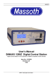
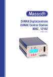
MASSOTH Bedienungsanleitung DiMAX 1200Z Digitalzentrale ab Firmware Version 2.0 Version 5.0 – Mai 2005 DiMAX 1200Z Digitalzentrale V5.0 05/05 MASSOTH INHALTSVERZEICHNIS 1. Einleitung 2. Lieferumfang 3. Spezifikationen 3.1. Technische Eigenschaften 3.2. Leistungsumfang der Software 3.3. Eingabe- und Steuergeräte 3.4. LGB Eingabe- und Steuergeräte 4. Aufbau & Anschluss 4.1. Spannungsversorgung 4.1.1. Interner 230V~ Trafo 4.1.2. Externe Spannungsversorgung 4.2. Anschluss eines Steuergerätes 4.3. Starten der Digitalzentrale 5. Geräteinstellungen 5.1. Display 5.2. Bedienung 5.3. Menüeinstellungen 5.3.1. Fahrstrom 5.3.2. Buswandler Fahrstufentyp 5.3.3. Buswandler Lokabmeldung 5.3.4. Maximale Anzahl aktiver Adressen 5.3.5. Abschaltzeit bei Kurzschluss 5.3.6. Systemeinstellungen 5.3.6.1. Aktive Loks Speichern 5.3.6.2. Aktive Loks zurücksetzen 5.3.6.3. Lokspeicher löschen 5.3.6.4. Firmwareupdate 5.4. Systemmeldungen 5.4.1. Manuell ausgelöster Not-Stop 5.4.2. Überlastetes Digitalgleis 5.4.3. Kurzschluss auf Steuerbus 5.4.4. Kurzschluss auf Digitalgleis 5.4.5. Temperatur 6. Technische Daten 7. Garantie und Gewährleistungsanspruch 8. Kundendienst HERSTELLER MASSOTH ELEKTRONIK GMBH FRANKENSTEINER STR. 28 64342 SEEHEIM – MALCHEN TELEFON: +49 (0)6151 35077-0 TELEFAX: +49 (0)6151 35077-44 E-MAIL: [email protected] HOTLINE: [email protected] INTERNET: www.massoth.de WICHTIGE HINWEISE Copyright 2005 by MASSOTH ELEKTRONIK GMBH. Um ungetrübten Spielspaß mit diesem Produkt sicher zu stellen, lesen Sie diese Bedienungsanleitung bitte ausführlich. Dieses Produkt ist für Kinder unter 8 Jahren nicht geeignet. Das Produkt kann funktions- oder fertigungsbedingt scharfe Kanten aufweisen. Bei unsachgemäßem Gebrauch besteht Verletzungsgefahr. Betreiben Sie dieses Gerät nur an den in dieser Bedienungsanleitung angegebenen Geräten. Elektrische und mechanische Maßangaben sowie Abbil dungen ohne jede Gewähr. Irrtümer vorbehalten! Daten können sich ohne Vorankündigung ändern. Für Schäden durch unsachgemäße Behandlung oder Fremdeingriff be steht kein Garantieanspruch. Zuwiderhandlungen bewirken zwingend Garantieverlust und generelle Reparaturverweige rung. Berechtigte Beanstandungen werden kostenlos nach gebessert. Für Reparatur- oder Serviceleistungen über geben Sie das Produkt bitte Ihrem Fachhändler oder senden es ausreichend frankiert an den Hersteller. Unfrei zugesendete Ware wird nicht angenommen. MASSOTH® und DiMAX® sind eingetragene Warenzeichen der Firma MASSOTH ELEKTRONIK GMBH, Seeheim, Deutschland. LGB® ist eingetragenes Warenzeichen der Firma ERNST PAUL LEHMANN PATENTWERK, Nürnberg, Deutschland. Andere Warenzeichen sind ebenfalls ge schützt. © 2005 by MASSOTH ELEKTRONIK GMBH 1 DiMAX 1200Z Digitalzentrale V5.0 05/05 MASSOTH 1. EINLEITUNG • Öffnen Sie die DiMAX Digitalzentrale nicht. Dies kann Willkommen! Wir gratulieren Ihnen zum Erwerb der DiMAX 1200Z Digitalzentrale der Massoth Elektronik GmbH, dem Hersteller für Sound- und Digitalkomponenten für die LGB seit über 30 Jahren. Durch Ihre Funktionalität und einfache Bedienbarkeit sowie Leistungsfähigkeit setzt die DiMAX Di gitalzentrale neue Maßstäbe in der digitalen Modellbahn steuerung! Diese Bedienungsanleitung ist nur für DiMAX Digi talzentralen ab Firmwareversion 2.0 gültig. Nutzen Sie die DiMAX Digitalzentralen mit Firmware bis Version 1.3, so greifen Sie bitte auf Anleitungen der vierten Version oder früher zurück. Diese sind im Internet frei erhältlich. Mit diesem Handbuch können Sie Schritt für Schritt die neu en Möglichkeiten und Funktionen der DiMAX Digitalzentrale kennenlernen. Arbeiten Sie diese Anleitung vor der Inbe triebnahme sorgfältig durch. Wir wünschen Ihnen viel Spaß und Erfolg mit Ihrer DiMAX Digitalzentrale! WARNHINWEISE BEACHTEN SIE DIESE SICHERHEITSHINWEISE. BEI NICHTBEACHTUNG ERLISCHT DER GEWÄHRLEIS TUNGSANSPRUCH. • Die DiMAX Digitalzentrale ist nur für den Betrieb von di gitalen Modelleisenbahnanlagen geeignet. • Die DiMAX Digitalzentrale kann und darf nur mit den in dieser Anleitung beschriebenen Digital- Komponenten betrieben werden. Eine anderweitige Verwendung ist nicht zulässig. • Schließen Sie die DiMAX Digitalzentrale nur an die in dieser Anleitung beschriebenen Geräte an. Auch wenn andere Geräte die gleichen Steckverbinder verwenden, ist der Betrieb mit diesen Gerät nicht möglich. Es führt zur Beschädigung der DiMAX Digitalzentrale, sowie der anderen Komponenten. • Achten Sie bitte darauf, dass die DiMAX Digitalzentrale niemals herunterfällt. Setzen Sie die Zentrale keinen Stößen oder Schlägen aus und schütteln Sie sie nicht. Dies kann zur Beschädigung des Gerätes führen. zu Beschädigung und Beeinträchtigung des Gerätes führen. Darüber hinaus erlischt der Garantie- und Ge währleistungsanspruch. • Reinigen Sie die DiMAX Digitalzentrale niemals mit scharfen Reinigungsmitteln, Reinigungslösungen oder ätzenden Chemikalien. • Wir weisen hier ausdrücklich darauf hin, dass diese Zentrale kein Spielzeug ist. Lassen Sie die Zentrale niemals unbeobachtet. Kinder sollten nur in Begleitung Erwachsener eine Anlage mit der DiMAX steuern. Ge ben Sie hier bitte besonders acht! • Verwenden Sie Digitalprodukte nie mit einem analogen Trafo / Transformer auf der gleichen Modellbahn anlage. Dies gilt auf für Digitalprodukte im Zusammen hang mit einem Oberleitungsbetrieb. • Schließen Sie die Westernstecker der Digitalzentrale niemals an das Telefonnetz an. Dies führt sofort zu un reparablen Schäden. • Halten Sie die Lüftungsschlitze und Belüftungsöff nungen immer frei. Die entstehende Wärme wird da durch abgeführt. Führen Sie niemals Gegenstände oder Flüssigkeiten in die Belüftungsöffnungen ein. Schützen Sie die Digitalprodukte vor Feuchtigkeit. • Überprüfen Sie die Digitalkomponenten bitte regelmä ßig. Sollte eine Komponente beschädigt sein, so entfer nen Sie diese bitte sofort. • Irrtümer und Änderungen aufgrund des technischen Fortschritts bleiben vorbehalten. Jede Haftung für Schäden, Folgeschäden durch nicht bestimmungsge mäßen Gebrauch, Nichtbeachtung dieser Gebrauchs anweisung, Betrieb mit nicht für Modellbahnen zuge lassenen, umgebauten oder schadhaften sonstigen elektrischen Geräten, eigenmächtigen Eingriff, Gewalt einwirkung, Überhitzung, Feuchtigkeitseinwirkung u.ä. ist ausgeschlossen; außerdem erlischt der Gewährleis tungsanspruch. • Durch das Entfernen des Sicherheitsetiketts bzw. des Typenschildes erlischt der Garantieanspruch sofort und unwiderruflich. • Setzen Sie die DiMAX Digitalzentrale niemals direkter Wärme- bzw. Sonneneinstrahlung oder Feuchtigkeit aus. Dies kann die Funktion beeinträchtigen. DiMAX 1200Z Digitalzentrale V5.0 05/05 2 MASSOTH 2. LIEFERUMFANG Im Lieferumfang der DiMAX 1200Z Digitalzentrale sind folgende Komponenten enthalten: • 1 x DiMAX 1200Z • 1 x Anschlussstecker • 1 x Handbuch deutsch bzw. englisch • 1 x Netzkabel Sollte eine dieser Komponenten nicht im Lieferumfang ent halten sein, so wenden Sie sich bitte an Ihren Fachhändler. Er ist Ihnen gerne behilflich. 3. SPEZIFIKATIONEN 3.1. TECHNISCHE EIGENSCHAFTEN Die DiMAX 1200Z Digitalzentrale ist als hochwertiges Kom paktgerät konzipiert und besitzt neben der 12 Ampere End stufe und zwei CPUs zur Datenverarbeitung einen in tegrierten 230V~ Trafo. Technische Spezifikationen: – 12 Ampere Endstufe – 230 Volt~ Trafo integriert – Fahrstrom: 24 Volt DCC – Updateinterface – Programmierinterface – Programmiergleisausgang – PC Steuerungsinterface (i.V.) – Kurzschlusserkennung – temperaturgesteuerter Lüfter – Abschaltzeit bei Kurzschluss variabel – externe Spannungsversorgung möglich – Boosterschnittstelle 3.2. LEISTUNGSUMFANG DER SOFTWARE Um einen erweiterten Funktionsumfang bieten zu können, wird die DiMAX 1200Z Digitalzentrale ab Mai 2005 mit dem neuen MASSOTH - Steuerbusprotokoll ausgeliefert. Damit ändern sich die technischen Eigenschaften erheblich. Firmware bis 1.x ab 2.0 Steurbusprotokoll LGB MZS II MASSOTH Gleisprotokoll NMRA (eingeschränkt) NMRA (100%) Das MASSOTH - Steuerbusprotokoll bietet ab Version 2.0 einen umfassenden Funktionsumfang. Dazu gehören unter Anderem die folgenden Funktionen: 3 Funktionsumfang des neuen Protokolls Lokadressen 10239 Fahrstufen 14; 28; 128 Funktionen 16 Funktionsverarbeitung parallel + seriell (individuell für jede Lok einstellbar) Traktionen 16 mit je 4 Elementen Weichenstraßen 16 mit je 15 Elementen maximale Anzahl gesteuerter Loks 32 3.3. EINGABE- UND STEUERGERÄTE Mit Einsatz des neuen MASSOTH - Steuerbusprotokolls, ist es notwendig, neue Eingabegeräte einzusetzen. Zu diesen gehört unter Anderem der DiMAX Navigator. Er wird direkt an der Zentrale betrieben. 3.4. LGB EINGABE- UND STEUERGERÄTE Aus technischen Gründen können LGB Steuergeräte, wie zum Beispiel das LGB Lokhandy oder das LGB Universalhandy am neuen Steuerbusprotokoll nicht mehr direkt an der DiMAX 1200Z Digitalzentrale angeschlossen werden. Es besteht jedoch die Möglichkeit, sie mit Hilfe des DiMAX 600A Buswandlers im gewohnten Funktionsumfang weiter zu nutzen. Der Buswandler wird als passives Eingabegerät an der DiMAX 1200Z Digitalzentrale betrieben und bedarf selbst keiner Einstellung oder Konfiguration. Weitere Informationen zum Einsatz des Buswandlers finden Sie in Kapitel 5.3.2. 4. AUFBAU & ANSCHLUSS 4.1. SPANNUNGSVERSORGUNG 4.1.1. INTERNER 230V~ TRAFO Schließen Sie die Digitalzentrale DiMAX 1200Z an die Gleise an und stellen Sie diese vor Feuchtigkeit und Hitze geschützt auf. Verwenden Sie hierzu zum Beispiel das LGB Gleisanschlußkabel Nr. 50160. Achten Sie bitte darauf, dass Ihre Zentrale immer ausreichend belüftet wird und nicht im Bereich von Wärmequellen (z.B. Heizkörper) steht. Schließen Sie nun die Digitalzentrale DiMAX 1200Z mit dem mitgelieferten Anschlusskabel an eine geeignete Strom quelle an. Der integrierte Trafo ist nur für eine Versorgungs spannung von 230 Volt Wechselstrom geeignet und kann nicht mit 110 Volt Wechselstrom betrieben werden (z.B. für Betrieb in den USA). 4.1.2. EXTERNE SPANNUNGSVERSORGUNG DiMAX 1200Z Digitalzentrale V5.0 05/05 MASSOTH Sollten Sie keine Spannungsquelle mit 230 Volt Wechsel strom zu Verfügung haben, so können Sie die Zentrale auch durch die ext. Spannungsquelle (16 Volt bis max. 24 Volt Gleichspannung bei max. 15 Ampere) versorgen. Schließen Sie die Zentrale niemals über eine externe Spannungs quelle an, wenn Sie diese bereits an einer Steckdose mit 230 Volt Wechselspannung betreiben. Hat die Zentrale die Startprozedur korrekt durchlaufen, befindet sie sich automatisch im Fahrbetrieb. Im Betrieb zeigt das Display verschiedene Informationen über den Zustand der Anlage an. Fahrbetrieb 2L Ig:10,3A MAX:12A AZ: 0,4s Ugl:24V STOP MENÜ 4.2. ANSCHLUSS EINES STEUERGERÄTS Verbinden Sie den DiMAX Navigator mit einer der Buchsen auf der Frontseite der DiMAX Digitalzentrale. Die Buchsen sind mit CONTROL BUS gekennzeichnet. Auf der Frontseite befinden sich 4 Buchsen, zwei weitere befinden sich auch auf der Rückseite. Natürlich wird hier auch der DiMAX Funkempfänger angeschlossen. Ideal für den Anschluss des Funkempfängers ist die Rückseite der Zentrale geeignet, da keine direkte Interaktion mit dem Modul erfolgen muss. Dazu gehören: – Anzahl der aktiven Loks – aktueller Fahrstrom auf dem Gleis – eingestellter maximaler Fahrstrom – Abschaltzeit bei Kurzschluss – Spannung des Trafos oder externen Stromversorgung – Belegung der 3 roten Tasten unterhalb des Displays 4.3. STARTEN DER DIGITALZENTRALE 5.2. BEDIENUNG Haben Sie die DiMAX 1200Z Digitalzentrale mit einer Spannungsqueller verbunden, wird sie mit dem Power Schalter auf der Frontseite eingeschaltet. Bei jedem Start der Digitalzentrale wird ein System- und Softwaretest durch geführt. Die Bedienung der Zentrale erfolgt über die 3 roten Tasten unterhalb des Displays. Die Belegung der Tasten ändert sich je abhängig von dem entsprechenden Displayinhalt und wird immer in der untersten Zeile des Displays angezeigt. Im Fahrbetrieb besteht die Möglichkeit, über die Tasten zum Beispiel ein NOT-STOP (Taste STOP ) auszulösen oder das Menü zu öffnen. Checking Firmware please wait... 5.3. MENÜEINSTELLUNGEN 5.3.1. AUSGANGSSTROM DiMAX 1200Z made by MASSOTH ELEKTRONIK GMBH #12345 V2.0 Displaymeldungen bei Systemstart Im Display werden die Herstellerdaten, die Seriennummer und die Version der installierten Firmware angezeigt. Tritt während dem Systemtest ein Fehler auf, so startet die Zentrale automatisch das Firmwareupdate zum Einspielen einer neuen Firmware. Detaillierte Information zum Ablauf des Firmwareupdates finden Sie in Kapitel 5.3.6.4 FIRMWARE FAILURE STARTING SOFTWAREUPDATE Displaymeldung bei Systemfehler 5. GERÄTEINSTELLUNGEN 5.1. DISPLAY DiMAX 1200Z Digitalzentrale V5.0 05/05 Passen Sie den Ausgangsstrom an Ihre persönlichen Bedürfnisse an. So ist die Zentrale immer auf Ihre individuellen Anforderungen eingestellt und reagiert optimal. Bei einer kleinen Anlage mit wenigen Loks ist es ratsam den maximalen Fahrstrom zu reduzieren um die Belastung der Elektronik im Fall eines auftretenden Kurzschlusses so gering wie möglich zu halten. Der maximale Ausgangsstrom kann in drei Stufen 4; 7 und 12 Ampere eingestellt werden. Ausgangsstrom maximal begrenzt auf: Ia:12A WEITER + Einstellen des maximalen Fahrstroms 5.3.2. BUSWANDLER FAHRSTUFENTYP Die beliebten und formschönen LGB Steuerkomponenten können durch Ihre technischen Eigenschaften nicht direkt am MASSOTH-Busprotokoll betrieben werden. Mit Hilfe des 4 MASSOTH DiMAX 600A Buswandlers können jedoch die LGB Steuer komponenten ohne Einschränkung weiter genutzt werden. Dieser stellt dabei einen LGB Steuerbus zur Verfügung, an dem die Komponenten angeschlossen werden können. Gleichzeitig wandelt er die Daten in das Format des neuen MASSOTH-Steuerbusses und sendet diese Daten an die DiMAX Digitalzentrale. Da LGB Steuerkomponenten nur 14 Fahrstufen verarbeiten, wären Sie dabei gezwungen, Ihre Loks weiterhin mit 14 Fahrstufen zu steuern. Mit dieser Opti on besteht die Möglichkeit, die 14 Fahrstufen des Buswand lers auf 28 Fahrstufen zu skalieren. Sie können also alle Ihre Loks mit 28 Fahrstufen fahren. Buswandler-D600A Fahrstufentyp: 14√ 28 14 WEITER 28 Buswandler: Fahrstufenskalierung 5.3.3. BUSWANDLER LOKABMELDUNG Steuern Sie eine Lok mit den LGB Steuerkomponenten, wird die Anmeldung der Loks durch den Buswandler vorge nommen. Wenn die Lok nicht mehr gesteuert wird, kann die Abmeldung auf zwei Varianten durchgeführt werden. Bei einer passiven Abmeldung wird die Lok für weitere Steuergeräte freigegeben, die Daten der Lok werden in der Zentrale dabei weiterhin verarbeitet. Die Lok bleibt aktiv. Bei einer aktiven Abmeldung, wird die Lok auch von der Zentra le freigegeben. Die Zahl der aktiven Loks in der Zentrale wird dadurch um eine Lok reduziert. Buswandler-D600A Lokabmeldung: aktiv√ passiv akt. WEITER pas. Buswandler: Lokabmeldung Konfiguration der aktiven Adressen 5.3.5. ABSCHALTZEIT BEI KURZSCHLUSS Fährt ein Zug in eine Kehrschleife ein, tritt ein Kurzschluss auf. Bei hoher Geschwindigkeit fällt der Kurzschluss kaum auf. Ist die Geschwindigkeit jedoch gering, steigt der fließende Kurzschlussstrom. Die Zentrale erkennt das und schaltet aus Sicherheitsgründen das Gleis ab. Damit das Einfahren des Zuges in eine Kehrschleife nicht als ungewünschter Kurzschluss erkannt und das Gleis abschaltet wird, können Sie in diesem Menüpunkt die Zeit bis zum Abschalten des Gleises einstellen. So toleriert die Zentrale diese Kurzschlüsse bis zu 0,8 Sekunden. Folgen 5 Kurzschlüsse in Abständen von jeweils maximal einer Minute, erwärmt sich die Zentrale schnell. Um die Elektronik zu schützen, wird für einen Moment ein temperaturbedingter NOTSTOP ausgelöst. Abschaltzeit bei Kurzschluss nach 0,4sec. WEITER + Einstellen der Abschaltzeit bi Kurzschluss 5.3.6. SYSTEMEINSTELLUNGEN 5.3.6.1. AKTIVE LOKS SPEICHERN Mit diesem Menüpunkt speichern Sie den Status Ihrer ak tiven Loks. Das bedeutet, dass die Befehle aller Loks, die zu diesem Zeitpunkt auf dem Gleis aktiv sind, gesichert werden. Der gespeicherte Zustand wird beim nächsten Ein schalten der Zentrale geladen und alle aktiven Loks be wegen sich, wie zum Zeitpunkt des Abspeicherns. Dieses Feature ist zum Beispiel besonders für automatisierte Show anlagen und große Privatanlagen interessant. Die gespei cherten Daten bleiben bis zur Löschung (Kapitel 5.3.6.2) be stehen. Sie können auch überschrieben werden. 5.3.4. MAXIMALE ANZAHL AKTIVER ADRESSEN Mit dieser Option wird die Anzahl der maximal steuerbaren Loks auf dem Gleis eingestellt. Loks werden als aktiv be zeichnet, wenn Sie fahren oder anderweitig Befehle emp fangen und Aktionen ausführen. Loks, die auf dem Gleis stehen, dabei jedoch keine Befehle empfangen, sind nicht aktiv. Für diese Loks werden in der Zentrale keine Daten verarbeitet. Im Auslieferungszustand sind 16 Adressen vor eingestellt. Die Anzahl aktiver Loks wird im Fahrbetrieb in der rechten oberen Ecke angezeigt. Maximale Anzahl aktiver Adressen auf Gleis: 16 WEITER + 5 Betriebszustand der aktiven Loks speichern: < WEITER √ Buswandler Lokabmeldung 5.3.6.2. AKTIVE LOKS ZURÜCKSETZEN Haben Sie vor dem Abschalten Ihrer Zentrale, den Zustand Ihrer aktiven Loks gespeichert, werden beim Einschalten der Zentrale diese Daten automatisch geladen und die Loks automatisch in Bewegung gesetzt. Möchten Sie diese Funktion beim nächsten Einschalten der Zentrale nicht mehr nutzen, so müssen Sie die gespeicherten Daten löschen. DiMAX 1200Z Digitalzentrale V5.0 05/05 MASSOTH Betriebszustand der konfg. Loks rücksetzen? < WEITER √ !NOT-STOP! ausgelöst von Steuerbusgerät aufheben Buswandler Lokabmeldung Notstop durch Steuerbusgerät 5.3.6.3. LOKSPEICHER LÖSCHEN 5.4.2. ÜBERLASTETES DIGITALGLEIS Alle genutzten Loks werden am DiMAX Navigator konfigu riert. Diese Loks können für kurzfristiges Spielen in Hand regler gespeichert werden. Es besteht auch die Möglichkeit, diese Daten in der Zentrale zu speichern. Dies empfiehlt sich für eine feststehende Anlage, auf der regelmäßig die gleichen Loks und Züge verkehren. Wird auf einem Hand regler eine Lok mit der Adresse 0008 geladen, gleicht der Handregler diese Adresse mit der Zentrale ab. Verfügt die Zentrale über eine Lok mit dieser Adresse, haben die Daten der Zentrale Priorität und senden die Information zum Handy. Dies übernimmt dann für den Moment diese In formationen. Ist das angeschlossene Digitalgleis überlastet, erscheint diese Notstop-Meldung auf dem Display. Üblicherweise ge schieht dies durch Überschreiten des eingestellten maxima len Ausgangsstroms (4; 7; 12A). Bitte passen Sie die Ein stellungen an oder verringern Sie die Last auf dem Gleis. Lokspeicher vollständig rücksetzen? < WEITER √ 5.3.6.4. FIRMWAREUPDATE Für neue Funktionen, kann über das PC Interface jederzeit die neuste Firmware eingespielt werden. Schließen Sie dazu ein serielles Kabel an das PC Interface der Digitalzen tale an und verbinden Sie die Zentrale mit Ihren Computer. Zum Durchführen eines Updates muss in der Zentrale der Updatemodus aktiviert werden. Dieser ist im Menü unter den Systemeinstellungen zu finden. Detaillierte Informa tionen zum Update gibt die Software. Diese finden Sie auf der MASSOTH-SERVICE-CD und im Internet. Firmwareupdate durchführen? WEITER Notstop durch Steuerbusgerät 5.4.3. KURZSCHLUSS AUF STEUERBUS Buswandler Lokabmeldung < !NOT-STOP! Digitalgleis überlastet aufheben √ Starten des Updatemodus 5.4. SYSTEMMELDUNGEN 5.4.1. MANUELL AUSGELÖSTER NOTSTOP Meldung des manuell ausgelösten Notstops. Der Notstop lässt sich vom Steuergerät oder direkt von der Zentrale über die Softkeys aufheben. Beachten Sie, dass die Steuergeräte nach dem Auslösen des Notstops erst nach 5 maligem blin ken der roten LED den Betrieb wieder aufnehmen können. DiMAX 1200Z Digitalzentrale V5.0 05/05 Ein Kurzschluss auf der Seite des CONTROL BUS löst diese Meldung aus. Der CONTROL BUS wird sofort abge schaltet. Bitte überprüfen Sie, dass alle Steuergeräte (Lokbzw. UniversalHandys usw.) richtig angeschlossen sind. Die Aufhebung des Notstops kann nur über die Zentrale er folgen. !NOT-STOP! Steuerbus überlastet aufheben Notstop durch Steuerbusgerät 5.4.4. KURZSCHLUSS AUF DIGITALGLEIS Ein Kurzschluss auf dem Gleis löst diese Notstop- Meldung aus. Nach dem Entfernen des Kurzschlusses kann der Not stop durch das Steuergerät oder die Softkeys aufgehoben werden. Anmerkung: Tritt innerhalb 5 Minuten mit max. 1 Minute Abstand (also 5 in 5 Minuten), jeweils 1 Kurzschluss auf, so erscheint die Meldung Übertemperatur für ca. 2 Mi nuten. Durch einen Kurzschluss entstehen an der Endstufe der Zentrale hohe Temperaturen. Zum Schutz der Elektronik schaltet die Zentrale für 2 Minuten die Ausgangsspannung ab, es werden keine Fahrbefehle entgegen genommen. !NOT-STOP! Kurzschluss auf Digitalgleis aufheben 6 MASSOTH ÜBERTEMPERATUR! Bitte warten bis Power-LED grün 5.4.5. TEMPERATUR Bei sehr hoher Umgebungstemperatur, schlechter Luftzu fuhr und hoher Belastung, kann es zur Abschaltung der Zentrale bei zu hoher Innentemperatur kommen. Der einge baute Lüfter kühlt die Zentrale innerhalb weniger Minuten auf Betriebstemperatur ab. Anschließend kann der Notstop wieder aufgehoben werden. 8. KUNDENDIENST Um Beratung, Hilfestellung oder Servicedienstleistungen in Anspruch zu nehmen, wenden Sie sich bitte an Ihren Fachhändler oder direkt an den Hersteller. Im Internet finden Sie detaillierte Informationen und Dokumentation zu diesem Produkt. Dort steht auch eine FAQ-Liste zur Verfü gung. Ebenso erhalten Sie auch neuste Software und Hand bücher. Wir empfehlen, Ihre Service- oder Produktanfrage per eMail, an: [email protected] zu senden. HERSTELLER: !NOT-STOP! durch Temperatur aufheben ÜBERTEMPERATUR! Bitte warten bis Power-LED grün 6. TECHNISCHE DATEN MASSOTH ELEKTRONIK GMBH FRANKENSTEINER STR. 28 64342 SEEHEIM – MALCHEN TELEFON: +49 (0)6151 35077-0 TELEFAX: +49 (0)6151 35077-44 E-MAIL: [email protected] HOTLINE: [email protected] INTERNET: www.massoth.de Beachten Sie für den Betrieb bitte folgendes: Spannungsversorgung über UE ± 230V~ integrierten Trafo 230V~ Stromaufnahme über IE max 3A integrierten Trafo MASSOTH® und DiMAX® sind eingetragene Warenzeichen der Firma MASSOTH ELEKTRONIK GMBH, Seeheim, Deutschland. LGB® ist einge tragenes Warenzeichen der Firma ERNST PAUL LEHMANN PATENTWERK, Nürnberg, Deutschland. Andere Warenzeichen sind ebenfalls geschützt. © 2005 by MASSOTH ELEKTRONIK GMBH Spannungsversorgung UE min 15V= über externe Spannungsquelle UE max 24V= Stromaufnahme über IE max 15A externe Spannungsquelle Fahrspannung UE max 24V DCC Fahrstrom IE max 12A Programmierstrom IE max 2A Steuerbusstrom IE max 2A 7. GARANTIE UND GEWÄHRLEISTUNGSANSPRUCH Massoth garantiert die Fehlerfreiheit dieses Produkts für ein Jahr. Darüberhinaus besteht in Deutschland ein Gewährleis tungsanspruch von 2 Jahren. Verschleißteile sind von der Garantieleistung ausgeschlossen, da diese Teile einer na türlichen Abnutzung durch Gebrauch des Gegenstandes un terliegen. Der Anspruch auf Serviceleistungen durch den Hersteller erlischt durch eine zweckentfremdete Nutzung so fort und unwiderruflich. 7 DiMAX 1200Z Digitalzentrale V5.0 05/05 MASSOTH Users Manual DiMAX 1200Z Digital Central Station for Firmware Version 2.X Version 2.0 – May 2005 DiMAX 1200Z Digitalzentrale V5.0 05/05 8 MASSOTH CONTENT 1. Introduction 2. Scope of Supply 3. Specifications 3.1. Technical Characteristics 3.2. Software Features 3.3. Remotes and Components 3.4. LGB Components 4. Setup & Connection 4.1. Power Supply 4.1.1. Internal 230V~ Transformer 4.1.2. External Power Supply 4.2. Connecting a Remote 4.3. Starting the Central Station 5. Settings 5.1. Display 5.2. Operation 5.3. Menu Settings 5.3.1. Maximum Operating Current 5.3.2. Transducer Steps of Speed 5.3.3. Transducer Loco Log out 5.3.4. Maximum Number of active Locos 5.3.5. Turn Off Time at Short Cirquit 5.3.6. System Settings 5.3.6.1. Save active Locos 5.3.6.2. Reset active Locos 5.3.6.3. Reset Loco Database 5.3.6.4. Firmwareupdate 5.4. System Messages 5.4.1. Manually triggered Emergency Stop 5.4.2. Overloaded Track 5.4.3. Short Cirquit on Control Bus 5.4.4. Short Cirquit on Track 5.4.5. Temperature 6. Technical Information 7. Liability 8. Service MANUFACTURER MASSOTH ELEKTRONIK GMBH FRANKENSTEINER STR. 28 64342 SEEHEIM – MALCHEN GERMANY PHONE: +49 (0)6151 35077-0 FAX: +49 (0)6151 35077-44 E-MAIL: [email protected] HOTLINE: [email protected] INTERNET: www.massoth.de IMPORTANT NOTES Copyright 2005 by MASSOTH ELEKTRONIK GMBH. In order to guarantee pure fun with this product, read this instruction carefully and in detail. This product is no toy. This product is not suitable for child ren under the age of 8 years. This product can have sharp edges because of function or production reasons. Because if the functional structure, the danger of sqeezing or wedging may exist. Small parts may be danger for swollowing. Keep away from children and untrained people. Danger of injury exists with inappropriate use. Only use this products in com bination with devices that are described in this manual. Given electrical and mechanical data as well as illustrations are without guarantee. Mistakes of any kind are reserved. Given data is subject to change without notive. No warranty claim exist for inappropriate treatment or foreign interfe rence. Offences cause compelling warrenty loss and general repair refuse. Entitled objections will be repaired free of charge. For repair service please hand this product to your retailer or send it directly to the manufacturer. Postage has to be paid by the customer. MASSOTH® and DiMAX® are registered trademarks of MASSOTH ELEKTRONIK GMBH, Seeheim, Germany. LGB® is a registered trademark of ERNST PAUL LEH MANN PATENTWERK, Nürnberg, Germany. Other trademarks are property of their respective owners. © 2005 by MASSOTH ELEKTRONIK GMBH 9 DiMAX 1200Z Digitalzentrale V5.0 05/05 MASSOTH 1. INTRODUCTION Welcome! We would like to thank you for purchasing a DiMAX Central Station of the Massoth Elektronik GmbH, the manufacturer for Sound- and digital components for LGB since 1973. This users manual is only valid for DiMAX Central Sta tions with Firmware 2.0 or later. If you have purchased a DiMAX Central Station with Version 1.8 or earlier, so please get the a users manual of version 4 or less. They are available on the Internet. With this manual to read about the features and possibilities of your DiMAX Central Station. Please read this manual carefully before starting the manual. Have Fun! WARNING REFERENCE CONSIDER THESE SAFETY REFERENCES. WARRAN TY CLAIM EXPIRES IF NEGLECTED. • The DiMAX Central Station is only suitable for the use of digital model train layouts in combination with the in dicated digital components. • The DiMAX Central Station can and may only be ope rated with components discribed in this manual. Other use is strictly permissible. • Attach the DiMAX Central Station only to the devices is not a Toy. Never leave the Central Station unguided. Children under the age of 8 should always be watched by their parents when playing with this Central Station. Please be very carefull in this case. • Never run the DiMAX Central Station combined with an analog transformer on the same layout. This applies also for overhead line power supply. • Never connect the DiMAX Central Station to the phone system nor connect phones with the Central Station. This will damage the components immediately. • Do not block the ventilation slots. The emerging heat will be exausted through these slots. Do never lead any liquids or articles into the ventilation slots. Protect these digital products from moisture. • Check the components of the digital system regularly. Remove any defect component immediately. • Mistakes and changes due to the technical progress, product care and other manufacturing methods remain reserved. Product liability for damage, damages by not intended use, neglect of this operating instruction, operation with not for modeltrains certified, converted or defective other electrical devices not for, arbitrary interference, impact, overheating, humidity effect etc. is impossible; in addition the warranty claim expires immediatly. described in this manual. Even if other devices use the same kind of jack (plug connectors), it is not possible to run them together. This might damage or destroy the Navigator as well as the other components. • Please make sure that the DiMAX Central Station ne ver drops or falls down. Expose it to no impacts nor vibration. This can lead to damages. • Never suspend the DiMAX Central Station to heat nor direct sunlight or humidity. This may impair the func tions. • Do never open the DiMAX Central Station nor remove the warranty seal from the back. Warranty will expire immediately if the seal is removed or damaged. • Never clean the DiMAX Central with strong solvents, cleanings solutions or corrosive chemicals. • We expressly point out, that this DiMAX Central Station DiMAX 1200Z Digitalzentrale V5.0 05/05 10 MASSOTH 2. SCOPE OF SUPPLY The following items come packed with the DiMAX Central Station: • 1 x DiMAX 1200Z Central Station • 1 x Connection Plug • 1 x Users Manual deutsch bzw. englisch • 1 x Power Cable If one of these components if missing, please contact your retailer for help and replacement. 3. SPECIFICATIONS 3.1. TECHNICAL CHARACTERISTICS The DiMAX 1200Z Central Station is a high quality compact unit that comes with an internal 230 Volt AC transformer besides the dual-CPU and 12-Amp Power Unit. Technical characteristics – 12 Amp Power Unit – 230 Volt~ Transformer integrated – Output Current: 24 Volt DCC – Updateinterface – Programminginterface – Programming Track – PC Control Interface (i.V.) – Short Cirquit Detection – integrated temperature controled vent – variable track turn off at short cirquit – external power supply ready – booster connection 3.2. SOFTWARE FEATURES To offer an enhanced feature range, the DiMAX 1200Z Central Station comes the new MASSOTH protocol starting May 2005. Thus changes the technical characteristics substantially. Firmware 1.x 2.0 or later Control Bus Protocol LGB MZS II MASSOTH Protocol on Track NMRA (eingeschränkt) NMRA (100%) The MASSOTH - Protocol offers a wide range of enhanced features. This contains the following features for example: 11 Features 10239 14; 28; 128 16 parallel or serial (can be configured for every loco) Tractions (Multi-Heading) 16 with 4 elements each Routes 16 with 15 elements each Maximum number of trains that 32 can be controlled at the same time Loco addresses Steps of speed functions Function data transmission 3.3. REMOTES AND COMPONENTS With the new protocol, new bus components and remotes are required. The new DiMAX Navigator is one of those new remotes. It is connected directly to the Central Station. 3.4. LGB COMPONENTS For techical reasons, all LGB components like the Loco Remote or the Universal Remote can not be connected to the DiMAX Central Station with the new protocol anymore. But it is possible to use the DiMAX 600A Transducer as a translater from LGB MTS II to the MASSOTH protocol. So LGB components can still be used. The Transducer is a passive device that needs no configuration. Read more about the Transducer in chapter 5.3.2 4. SETUP & CONNECTION 4.1. POWER SUPPLY 4.1.1. INTERNAL 230V~ TRANSFORMER Connect the DiMAX Central Station with the Track and place it on a place that is dry and cool (not hot). You could use the LGB Track Connection Cable No. 50160. Please take care that the Central Station always gets enought air and is not placed close to other warm items as heating sys tems for example. Then connect the DiMAX 1200Z Central Station with the supplied power cable to a power source. The integrated transformer is only capable for a power source with 230 Volt AC (Alternating Current) only and can not be used with 110 Volt AC as for example in the US. 4.1.2. EXTERNAL POWER SUPPLY If no 230 Volt power source is available, also an external power source can be used. 16 to 24 Volt DC (direct current) are required. Never connect the Central Station to both power sources at the same time. DiMAX 1200Z Digitalzentrale V5.0 05/05 MASSOTH 4.2. CONNECTING A REMOTE Connect the DiMAX Navigator with its cable to one of the connectors in the centrals from panel. The connectors carry the title CONTROL BUS . The DiMAX 1200Z Central Station has 4 connectors in the front and two more on the back. Also the DiMAX RC Receiver has to be connected to one of those connectors. Therefor the connectors on the back side are perfect, since there is no direct interaction to be done with the Receivers. For example: – Number of active locos – actual operating current – maximum operation current – turn of time at short cirquit detection – voltage of transformer or external source – button functions 5.2. OPERATION 4.3. STARTING THE CENTRAL STATION If the Central Station has been connected to a power source use the Power Button on the front side to turn it on. Every time the Central Station starts, a software- and hardwaretest is performed. Checking Firmware please wait... DiMAX 1200Z made by MASSOTH ELEKTRONIK GMBH #12345 V2.0 System messages at Start The display will show the manufacturer information, serial number and also the installed firmwareversion. IF a failure occurs, the Central Station will automatically start the Firmwareupdate. Detailed information about a firmwareupdate can be found in chapter 5.3.6.4 The central station is operated with the three red buttons placed below the display. The function may vary from situati on to situation and is always given in the displays last line. In the operation mode, an emergency stop STOP can be triggered or the systems menu can be entered. 5.3. MENU SETTINGS 5.3.1. MAXIMUM OPERATING CURRENT Adjust the maximum operation current to your layouts needs. Then the central station is always adjusted to your layouts requirements and will be able to interact precisely. We recommend to lower set the maximum operating current if the central station is connected to a small layout to decrease the components load at a short cirquit. The maximum output current can be set in three steps to: 4; 7 or 12 amps. Maximum output current on track Ia:12A NEXT + Einstellen des maximalen Fahrstroms FIRMWARE FAILURE STARTING SOFTWAREUPDATE message at system failure 5. SETTINGS 5.1. DISPLAY After booting the system correctly, the central station will automatically enter the operation mode. The display will show several interresting informations. Operation: 2L Ig:10,3A MAX:12A AZ: 0,4s Ugl:24V STOP MENU 5.3.2. TRANSDUCER STEPS OF SPEED Because of technical restrictions, it is not possible to run the LGB MTS II components on the new MASSOTH protocol. But the DiMAX 600A Transducer can be used as a trans lating module to connect the LGB MTS II items to a DiMAX Central Station with the new MASSOTH protocol. Since all LGB MTS II components only work with 14 steps of speed, you would still be forced to run all your locos with 14 steps of speed. This option allows to scale the 14 steps of speed to 28. So all locos can be run with 28, which we rec comend. Transducer-D600A Steps of Speed: 14√ 28 14 NEXT 28 Transducer: Scaling the Steps of Speed DiMAX 1200Z Digitalzentrale V5.0 05/05 12 MASSOTH 5.3.3. TRANSDUCER LOCO LOG OUT If LGB MTS II components are used to drive your locos, the Transducer will log in the loco and reserve it for this hand control. After 20 seconds of non use the Transducer will log of the loco. It is not longer reserved for this remote. This log out can be realized in two ways: The active log out will also log out the loco in the central station. This means, the num ber of active locos in the central station will drop by one. If the locos are logged of passive, they still remain active in the central but can be reserved and controlled ba another remote. Compare this option to the amount of allowed active locos. Buswandler-D600A Loco log out: active√ passive act. NEXT pas. Transducer: Loco log out 5.3.4. MAXIMUM NUMBER OF ACTIVE LOCOS Define the maximum number of active locos on track, which means locos, that are controlled at the same time. Locos are active when they recieve data from a remote. Locos that are just standing on the track but not reserved for a player are not active so the Central Station does not generate any data for them even when the sound of those locos is on. The fac tory settings is 16 addresses. The number of active locos is displayed in the top right cornder of the operation mode. Maximum number of active locos on track: 16 NEXT + maximum number of active locos 5.3.5. TURN OFF TIME AT SHORT CIRQUIT If a train enters or leaves a reverse loop, a short cirquit will occur always. At a high speed the short cirquit will not be realized, but if the speed is very low or the tracks are short cirquit in any other way, the central station will detect the short cirquit and shut down the track power until the short cirquit has been removed. The time between the short cirquit detection and the moment when the Central Station will turn off the track can be set to prevent the central station turning off the track when the train enters just the reverse loop. Up to 0.8 seconds time can be set. 0,4 Seconds are set as factory default. If 5 short cirquits occur within 1 minute each the Central Station will go into a safety mode and turn of the track for a short moment to not everheat the system. An emergency stop is released. 13 Turn off Time at Short Cirquit detect. 0,4sec. NEXT + Turn off time at short cirquit 5.3.6. SYSTEM SETTINGS 5.3.6.1. SAVE ACTIVE LOCOS Use this feature to save your active locos that are currently running on the track. When the Central Station is turned on again the next time, all running trains will continue at the same direction and speed with exactly the same settings. This feature is especially interesting for automated show lay outs and large private layouts. The saved data will remain in the station until it is deleted again (chapter 5.3.6.2). The sa ved data can also be overwritten. Save all active locos on track < NEXT √ Saving active locos 5.3.6.2. RESET ACTIVE LOCOS Did you save the active locos before turning of the layout the central station will start driving all these trains again after tur ning it on again. To stop this function the active locos can be reset with this option. Reset active locos on track < NEXT √ Reset active locos on track 5.3.6.3. DELETE LOCO DATABASE Alle used locos are configured in the DiMAX Navigator. This data can be saved for a single moment in the Navigator or stored in the Central Station for future play. This is recom mended for a permanent layout. If the address 0008 is entered on the Navigator, the Navigator will check this num ber with the Central Stations database and load this in formation, even if the Navigator has another setting itself. This feature is important, since the Central Station usually is always connected to the layout, but the handhelds may vary from user to user. If you want to delete the whole database use this function but be sure, that you want to delete the whole set. DiMAX 1200Z Digitalzentrale V5.0 05/05 MASSOTH 5.4.3. SHORT CIRQUIT ON CONTROL BUS Delete loco database < NEXT √ Delete loco database 5.3.6.4. FIRMWAREUPDATE For new features the DiMAX Central Stations software can be updated anytime with the integrated PC Interface. Just a serial 9-pin cable is requried to connect the Central Station with the Computer (IBM compatible). USB is not supported. To perform an update just active the Updateoption in the menu. This is also required for Updates on other DiMAX items as for example the DiMAX Navigator. The software is available on the Internet and also the MASSOTH-SERVICECDs that might be attached to your product. Firmwareupdate? < NEXT √ Starting a Firmwareupdate 5.4. SYSTEM MESSAGES 5.4.1. MANUALLY TRIGGERED EMERGENCY STOP Message of a manually triggered emergency stop. Release it from your remote or the Centrals right button as shown on the display too. The emergency stop may be released after several red light flashing. !EMERGENCY-STOP! triggered from remote release Emergency Stop from remote 5.4.2. OVERLOADED TRACK If the track current is overloaded, this emergency stop mes sage will be displayed. This usually happens when the maxi mum operating current is exceeded. Please adjust the operting current again. !EMERGENCY-STOP! Track overloaded release Emergency Stop from overloaded track DiMAX 1200Z Digitalzentrale V5.0 05/05 If a short cirquit on the control bus occurs, this message will be displayed and the control bus will be shut down immedia tely. Please check all your bus components if they are connected correctly. The release is only available from the central station! !EMERGENCY-STOP! Control bus overloaded release Notstop durch Steuerbusgerät 5.4.4. SHORT CIRQUIT ON TRACK A short cirquit on track will show this message. An emergen cy stop is triggered automatically. After removing the short cirquit, it can be released from a remote or the central stati on. If 5 short cirquits occur in five minutes, the central will trigger an emergency stop to protect the central station from overheating. The overtemp message OVERTEMP will be shown for about 2 minutes. !EMERGENCY-STOP! Short cirqut on track release OVERTEMP! Please wait until Power LED turns green 5.4.5. TEMPERATURE At a very high temperature and bad air ventilation and also high demand, the central might turn off the track since the temerature is to high for it to work. The integrated vent will cool down the central within a few minutes. Afterwards the emergency stop can be released with ease. !EMERGENCY-STOP! by temperature release OVERTEMP! Please wait until Power-LED turns green 14 MASSOTH 6. TECHNICAL INFORMATION Please be informed about the following information: MANUFACTURER: Power Supply with UE ± 230V~ integrated transformer with 230V~ Required Amps for IE max 3A internal Transformer Power Supply with UE min 15V= external Source UE max 24V= Required Amps IE max 15A for external Source Track Operation Current UE max 24V DCC Maximum Ampage on Track IE max 12A Ampage for Programming IE max 2A Ampage on Control Bus IE max 2A 7. LIABILITY Massoth warrants for one full year of service for this product. On top of this, you might have additional requirements from country to country. Wearing parts are not included in the warranty since these items wear out while time passes. You guarantee voids if the product is used in a not defined way. MASSOTH ELEKTRONIK GMBH FRANKENSTEINER STR. 28 64342 SEEHEIM – MALCHEN GERMANY PHONE: +49 (0)6151 35077-0 FAX: +49 (0)6151 35077-44 E-MAIL: [email protected] HOTLINE: [email protected] INTERNET: www.massoth.de MASSOTH® and DiMAX® are registered trademarks of MASSOTH ELEKTRONIK GMBH, Seeheim, Germany. LGB® is a registered trademark of ERNST PAUL LEHMANN PATENTWERK, Nürnberg, Germany. Ohter trademarks are property of their respectice licensee. © 2005 by MASSOTH ELEKTRONIK GMBH 8. SERVICE For consultation, assistance or service, please contact your retailer or the manufacturer. The website will give you detai led information and documents about this product. Also a FAQ-List is included. Latest software releases and manuals can be found there also. We suggest to contact the manu facturer over the hotline-eMail-address: [email protected] 15 DiMAX 1200Z Digitalzentrale V5.0 05/05