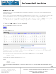
1
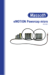
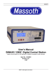
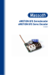
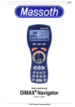
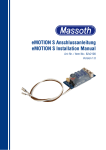
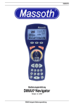
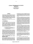
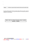
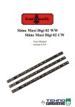
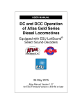
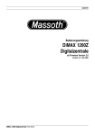
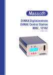
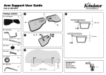
DiMAX 530S
®
Motor/Switch Decoder 8156001
Version 1.0 – 11/07
DiMAX 530S Motor/Switch decoder – 8156001
1 Brief Discription
The DiMAX® Motor/Switch Decoder is an all-purpose decoder with 8 switch outputs. These outputs may
be controlled digitally or by reed reais or other switches.
The DiMAX® Motor/Switch Decoder may be e.g. utilized to control the boom of a crane horizontally and
vertically as well as the bucket or the winch.
Programming is achieved with CV settings which can be programmed by every digital system. Additionally
the DiMAX® Motor/Switch Decoder supports PoM (Programming on the main track). The DiMAX®
Motor/Switch Decoder is able to control all switch drives available on the market: coil-operated (2-lead
and 3-lead) as well as motor driven.
A special feature is the capability to operate 6 programmable inputs by contact triggering. This facilitates
the direct operation of a switch by a push-button on a control board or by a triggered track contact.
1.1 Features of the DiMAX® Motor/Switch Decoder
• Digital Motor/Switch Decoder for NMRA-DCC compatible operation
• Up to 8 function outputs (incl. 3X2 for motor or EPL drive)
• Up to 6 inputs for manual control
• Overload protection for all functions
• Hook up via a 17 pole C-clamp
• Controllable by either loco addresses (1..10239) or switch addresses (1..2048)
• Convenient function mapping when using loco addresses including direction assignment.
• Programmable flashing light function and short term function
• Multiple programming options (Register, CV, PoM)
• Reset function for all CV values
1.2 Scope of Supply
- DiMAX® 530S Motor/Switch Decoder
- Manual
Please contact Massoth Electronics USA if any of the above components are damaged or missing.
2 Hook-Up and Operation
• Check the applicable wiring diagram for the hook-up method. Basically the decoder is protected against
short-circuit and overload. However in case of a connection error (e.g. function and track power) this
safety feature cannot work and the decoder will be destroyed subsequently.
®
• The factory setting of the DiMAX Motor/Switch Decoder is address 1..3. In case a loco address is to be
used, CV 29 must be altered accordingly.
®
• Place the DiMAX Motor/Switch Decoder in a protected location. The unit must not be exposed to
moisture and high temperature changes.
®
• The DiMAX Motor/Switch Decoder must only be connected to digital central stations for model railroads
according to the NMRS standards. Connecting the module to other appliances may lead to the
destruction of the unit.
• This unit is not a toy!
DiMAX 530S Motor/Switch decoder – 8156001
1
2.1 Contact Assignment
2.1.1 Function Outputs
• The function outputs 1+2 (SW1) , 3+4 (SW2) and 5+6 (SW3) are coupled. These outputs feature a dual
power amplifier to facilitate the operation of switch drives in two directions. Therefore these coupled outputs must never be operated at the same time. An intelligent protection software inhibits the operation in
one direction in case the reverse direction output is switched on at the same time. The outputs 7+8 are regular outputs, they are not coupled.
• The terminals of F7+F8 (K5+K6) have a dual function. In the switch mode (CV29-Bit7 = 1) the functions
F7 + F8 are not available. In the loco mode the functions F7 + F8 are only usable if the contact inputs K5
and K6 are deactivated.
• The function outputs are freely programmable in the loco mode. (F-key assignment and direction dependent control).
®
• Note: Make sure the speed step setting of the DiMAX Motor/Switch Decoder is the same as the setting
of the digital system used. Otherwise the light functions will not work properly. The light might blink or
might not work at all.
Illustration 1: Switch Hook up
2.1.2 Contact Inputs
• The contact inputs may be used for the manual operation of switches (e.g. operate a switch by triggering
a track contact). Alternatively they may be used as inputs for limit or position switches for a function.
• The contacts are firmly linked to the respective function outputs. K1+K2 control F1+F2 (SW1) , K3+K4
control F3+F4 (SW2) , K5+K6 control F5+F6 (SW3).
DiMAX 530S Motor/Switch decoder – 8156001
2
Illustration 2: Contact controlled switches
2.1.3 Additional Applications
e.g. dual coil drive, electrical motors, light bulbs
Illustration 3: Switch with dual coil drive
DiMAX 530S Motor/Switch decoder – 8156001
3
Illustration 4: Motor- / Light Bulb hookup
3 Settings and Programming
All described programming methods (except PoM) are to be executed on a programming track. Check
the manual of your central station or programming module for the correct procedure. In CV2 a
programming lock may be set to avoid accidental programming of the module.
Illustration 5: Programming
CV2=77: Programming lock deactivated (default)
CV2=0: Programming inhibited (except CV2).
In order to receive a programming confirmation, a load of at least 80mA must be connected to F1, e.g. a
switch motor. This enables the module to send back a confirmation signal to the central station.
Programming will be achieved at all times even if there is no confirmation signal possible.
Note: The programming methods shown below are not supported by all digital systems.
DiMAX 530S Motor/Switch decoder – 8156001
4
Register direct
CVs 1..4 are directly programmable
CV indirect
All changeable CVs may be programmed by „Register direct“.
Enter CV-Number in Reg. 6 , thereafter write CV-value in Register 5.
Write CVs
All changeable CVs may be programmed.
Write CVs Bit by Bit
All changeable CVs may be programmed.
Read CVs
Read all CVs.
Program on Main (PoM) All changeable CVs are programmable except CV1. After programming the
decoder will perform a reset in order to activate the new settings. PoM is only
usable in the loco mode.
3.1 Programming binary values
Certain CVs consist of 'binary' values (e.g. CV29). This means that several settings are combined in one
single value. Each function has a digit and a value. Programming a CV of this kind requires all values to
be summed up. A deactivated function allways has the value '0', an activated function the value given in
the CV-table. Add up all values of the activated functions and write the sum in the CV.
Let's take the NMRA Configuration Register (CV29) as an example:
You intend to program normal driving direction, 28 speed steps, and high loco address. According to the
CV-table Attachment1 this comes up to: 2+32=34. This means you have to program '34' in CV 29.
3.2 Switch-or Loco Address
• Each component connected to a digital control system requires an address. In the NMRA-DCC System
there are three kinds of addresses: switch addresses (1..1024), low loco addresses (1..127) and high loco
addresses (128..10239). A decoder must be programmed with an address.
• The switch addresses are in CV 31 - 36. To enable the use of the switch addresses CV29-Bit 7 must be
'ON'.
CV31 = address / 256 (Only the integral value is to be programmed)
CV32 = address – (CV31 x 256)
• The short loco address is located in CV1. This position allows values up to 127. Additionally CV29-Bit 5
and Bit 7 must be 'OFF'.
• The long loco address is programmed in CV17 + CV18.
In addition CV29-Bit5 must be 'ON' and CV29-Bit7 must be 'OFF'.
The long address is calculated like the switch address:
For technical reasons '192' must be added to CV 17.
Let's calculate the address 3000 as an example.
3000 / 256 = 11,72 this results in = 11+192 = CV17=203
Please note that 192 must only be added to the final result! For the calculation of CV18 the value
is used without adding '192' (In this case 11)
The next step: 3000-(11x256) = 3000-2816 = CV18=189
Consequently CV 17 must be programmed with 203 and CV 18 with 189.
• All digital systems (e.g. the DiMAX System) feature comfortable address programming: all CVs including
CV29 are automatically calculated and programmed.
DiMAX 530S Motor/Switch decoder – 8156001
5
3.3 Resetting to Factory Setting
Writing 55 in CV7 resets all basic settings, writing 77 in CV7 resets all functions to factory settings. This
can only be adchieved with the 'Writing CVs' procedure.
See 'Attachment 3' for the values of the factory setting
3.4 CV-Values
CVs are usable with loco addresses (L), switch addresses(S) or with both (LS).
CV
Description
Default
L/S
Range
Note
1
Loco address
(Standard short)
3
L
1-127
If CV29,
Bit5 = 0
2
Programming Lock
77
LS
0 + 77
0 = locked
77 = unlocked
Register mode: Reg6 = CVaddr. , Reg5 = Value
---
---
---
(10)
---
---
5+6
7
Software Version
7
Decoder-Reset function
(2 ranges available)
---
---
55 / 77
8
Manufacturer ID
123
---
---
17
Long loco address (high byte)
18
Long loco address (low byte)
128
L
29
Configurations Register NMRA
128
LS
31
Switch address SW1 high
0
S
32
Switch address SW1 low
1
S
33
Switch address SW2 high
0
S
34
Switch address SW2 low
2
S
35
Switch address SW3 high
0
S
36
Switch address SW3 low
3
S
1..2048
41
F1 Command Allocation
1
L
0..16
0= Light 1..16=Function
42
F2 Command Allocation
2
L
0..16
0= Light 1..16=Function
43
F3 Command Allocation
3
L
0..16
0= Light 1..16=Function
44
F4 Command Allocation
4
L
0..16
0= Light 1..16=Function
45
F5 Command Allocation
5
L
0..16
0= Light 1..16=Function
46
F6 Command Allocation
6
L
0..16
0= Light 1..16=Function
47
F7 Command Allocation
7
L
0..16
0= Light 1..16=Function
48
F8 Command Allocation
8
L
0..16
0= Light 1..16=Function
DiMAX 530S Motor/Switch decoder – 8156001
128 ..
10239
Read only
(See attachment 3)
Read only
If CV29,
Bit5 = 1
See Attachment 1
1..2048
1..2048
6
CV
Description
Default
L/S
Range
Note
51
F1 Special Function
67
LS
See Attachment 2
52
F2 Special Function
67
LS
See Attachment 2
53
F3 Special Function
67
LS
See Attachment 2
54
F4 Special Function
67
LS
See Attachment 2
55
F5 Special Function
67
LS
See Attachment 2
56
F6 Special Function
67
LS
See Attachment 2
57
F7 Special Function
0
LS
See Attachment 2
58
F8 Special Function
0
LS
See Attachment 2
61
K1 Command
1
S
0=deactivated , 1= switch on ,
2=switch off
62
K2 Command
1
S
0=deactivated , 1= switch on ,
2=switch off
63
K3 Command
1
S
0=deactivated , 1= switch on ,
2=switch off
64
K4 Command
1
S
0=deactivated , 1= switch on ,
2=switch off
65
K5 Command
1
S
0=deactivated , 1= switch on ,
2=switch off
66
K6 Command
1
S
0=deactivated , 1= switch on ,
2=switch off
Value
Note
Attachment 1. (CV29) – NMRA-Configuration
Bit OFF (Value=0) Application ON
0 Normal Driving Direction Reverse Driv.Direction
1
1 14 Speed Steps
28 Speed Steps
2
5 Short Address (CV1)
Long Address (CV17+18)
32
7 Loco Address
Switch Address
128
DiMAX 530S Motor/Switch decoder – 8156001
Setting important for lights
7
Attachment 2. (CV51 .. 58) – Special Functions F1 + F2 + F3 + F4 + F5 + F6 +F7 + F8
Value
Application
Note
0
0 = Continuous Operation
(Standard Function)
1..15 Continuous Symmetric Flashing
(Time Base 0,25 sec per unit)
Output flashes symmetrically
(1..15) Short Term Function, Monoflop
+64 (Time Base 0,25 sec per unit)
Switch Function!
Output switches off automatically after
reaching the time limit. The additional value
must be added.
(1..15) Asymmetrical Flashing (Short) / Asymmetrical
+ 128 / Flashing (Long)
+192 1/3 ON – 2/3 OFF
Short ON/Long OFF
The additional value must be added.
16
Inverse Coupling with output F1 resp. F3
(Alternating flashing)
CV52: (F2 an F1) + CV54: (F4 an F3) + CV56:
(F6 an F5)
Attachment 3. (CV7) RESETTING
To reset the decoder to factory setting, insert the desired value into CV7.
RESET CV-Values for Reset Programming
55 1=3, 17=128, 18=128, 29=128, 31=0, 32=1, 33=0, 34=2, 35=0, 36=3
77 41=1, 42=2, 43=3, 44=4, 45=5, 46=6, 47=7, 48=8, 51=67, 52=67, 53=67, 54=67, 55=67, 56=67,
57=0, 58=0, 61...66=1
4 TECHNICAL SPECIFICATIONS
Power Supply: 12 .. 24V DCC (In peaks max. 27V)
Maximum Allowable Load: Max. 2Amps
Function Outputs : Max. 1,5Amps per Output
Contact Inputs : connected towards GND
Current Draw : approx. 30mAmps
Operating Temperatur Range: 32° .. 125° F
• To prevent condensation make sure the module is at operating temperatur before starting operation.
Dimensions: 78 x 68 x 20 (L/W/H)mm
5 Important Notice
Never suspend the DiMAX Motor/Switch Decoder to shock or stress. Avoid short circuits of the connecting
wires. Avoid bridging of neighbouring wires and do not crush the connecting wires.
5.1 Moisture
The housing of the DiMAX Motor/Switch Decoder is protected from splashed water. However it is not waterproof. This is the reason why this module must only be operated in a dry environment. Protect the module from moisture, humidity, and water. Moisture and humidity may limit the functionality significantly or
may destroy the unit.
DiMAX 530S Motor/Switch decoder – 8156001
8
5.2 Warranty
Massoth Electronics USA warrants this product for 1 year from the date of purchase. This product is warranted against defects in materials and workmanship. Peripheral component damage is not covered by
this warranty. Normal wear and tear, consumer modifications as well as improper use or installation are
not covered. Errors and changes excepted.
5.3 Important Notes
This product is not a toy. This product may have sharp corners and edges and may be harmful if swallowed. Handling the item may cause restraint injuries. If not trained properly do not handle this product;
have a professional install this item. Operate this product only with products posted in this manual. Electrical specifications and measurements are subject to change without prior notice.
5.4 Support
Please visit www.massoth.com. On our website the latest software and manuals are provided. For further
support and detailed questions you may contact your dealer or the manufacturer at (email) [email protected].
Hotline hours USA: 09:00 a.m. To 4:00 p.m. EST Mo thru Fr
Phone: 770-886-6670
FAX: 770-889-6837
5. Manufacturer information
Massoth Elektronik GmbH
Frankensteiner Str. 28
64342 Seeheim
Tel.: 06151 35077- 0
Fax: 06151 35077- 44
[email protected]
[email protected]
[email protected]
www.massoth.de
Massoth Electronics USA, LLC
6585 Remington Dr., STE 200
Cumming, GA 30040
Ph.: 770-886-6670
FX: 770-889-6837
www.massoth.com
Massoth® and DiMAX® are registered trademarks by Massoth Elektronik GmbH, Seeheim, Germany. LGB® is a registered trademark and property of its respective owner. All
other trademarks printed are registered trademarks as well. No parts of this work may be reproduced or transmitted in any form or by any means, electronic or mechanical, including photocopying and recording, or by any information storage or retrieval system without the prior written permission by Massoth Elektronik GmbH unless such copying is
expressly permitted by federal copyright law.
DiMAX 530S Motor/Switch decoder – 8156001
9