1
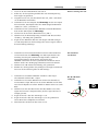
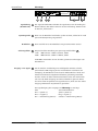
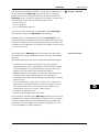
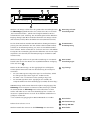
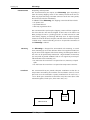
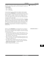
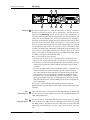
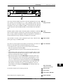
TRUE
systems
TM
P2 analog
Bedienungsanleitung
D
Version 1.2
User Manual
Version 1.1
E
P2analog
TRUE systems
P2analog
Vielen Dank für das Vertrauen, das Sie uns mit dem Kauf des P2analog
entgegengebracht haben. Der P2analog wurde entwickelt, um auch
bei den anspruchsvollsten Aufnahmen ein detailliertes und transparentes
Klangbild zu liefern. Die perfekte Kombination aus hochwertiger Technik
und praxisgerechter Ausstattung macht den P2analog zum optimalen
Partner für Aufnahmen aller Art.
Vorwort
Einleitung
Bitte scheuen Sie sich nicht, uns mit Ihren Fragen oder Anregungen zu
kontaktieren. Wir freuen uns immer von Ihnen und Ihren erfolgreichen
Produktionen zu hören.
In Anlehnung an unsere viel gefeierten TRUE Solo Preamps, bietet der
P2analog zwei Instrument Direct Inputs (DI), die ein Klangbild liefern,
das bis dato nur von High-End DI-Boxen bekannt war. Diese Eingänge
ermöglichen unglaubliche Präsenz und Kontrolle für Bässe und Gitarren, Detailtreue und Wärme für Streicher und Pianos. Durch die hohe
Eingangsimpedanz können Sie sogar den optimalen Sound aus Ihren
vintage Instrumenten herausholen!
Überblick
Auch im Zeitalter der großen Audio-Workstations und Software Plugins
bleibt die Plazierung von Mikrofonen ein kritischer Faktor, der das gesamte Klangbild maßgeblich beeinflußt. Die umfangreiche Ausstattung
des P2analog unterstützt Sie dabei, bei praktisch jeder Stereo-Aufnahme, das Optimum an Qualität zu erreichen.
Eine dieser Funktionen ist der integrierte M/S Dekoder, der eine detaillierte Kontrolle des Raumklangs ermöglicht. Mit einem minimalen Arbeitsaufwand bei der Mikrofonierung erhalten Sie ein beeindruckendes
Stereo-Bild, das Sie zudem noch kreativ verändern können.
Die M/S Technologie findet Ihren Einsatz in einer Vielzahl von Anwendungen, bei Raumklang in der Klassik, Overhead-Mikrofonie bei
Schlagzeugaufnahmen bis hin zu Gesang und akustischen Instrumenten
– wann auch immer eine akkurate Abbildung der Klangquelle und ihrer
Räumlichkeit gewünscht ist. Die M/S Mikrofonie verhindert auch den
„Loch-in-der-Mitte-Effekt“. Und ganz egal, ob Sie M/S, XY oder eine
andere Stereo-Mikrofonie-Technik anwenden, die Korrelationsgrad-Anzeige im P2analog wird Ihnen bei der Positionierung der Mikrofone für
ein perfektes Stereo-Bild ein große Hilfe sein.
D
Zusätzlich zu den eben genannten Funktionen bietet der P2analog :
• Dual Gain Bereiche zur Anpassung an die unterschiedliche
Empfindlichkeit von Mikrofonen
• Zuschaltbarer High-Pass Filter (40 Hz & 80 Hz), um Atem- und
Windgeräusche zu minimieren
• Relais-gesteuertes Signalrouting für einen möglichst
unverfälschten Signalweg
• Phasenumkehrschalter zur Korrektur von Polaritätsfehlern durch
falsche Positionierung der Mikrofone oder Probleme bei der
Verkabelung von XLR und Stereo-Klinke (TRS) Anschlüssen
• Phantomspeisung (48V)
TRUE systems
Sicherheitshinweise
P2analog
Wichtige Sicherheitshinweise
ACHTUNG! Hochspannung
Gefahr durch Stromschlag
Das Gerät nicht öffnen. Im Inneren befinden sich keine vom Benutzer reparierbaren Teile. Reparaturarbeiten dürfen nur von qualifiziertem Fachpersonal durchgeführt werden.
Netzanschluss
Bevor Sie das Gerät mit dem Stromnetz verbinden, überprüfen Sie bitte
sorgfältig, ob die richtige Versorgungsspannung eingestellt ist.
•
•
•
•
•
Verwenden Sie nur Sicherungen vom gleichen Typ
und gleichen Kenndaten.
Das Gerät muss geerdet sein.
Defekte Anschlussleitungen nicht verwenden.
Schließen Sie keine Ausgänge von Verstärkern an das Gerät an.
Betreiben Sie das Gerät nur in Übereinstimmung mit der
Bedienungsanleitung.
Feuchtigkeit
Um eine Gefährdung durch Feuer oder Stromschlag auszuschließen, darf
dieses Gerät weder Regen noch Feuchtigkeit ausgesetzt werden. Auch
Spritzwasser oder tropfende Flüssigkeiten dürfen nicht in das Gerät gelangen. Stellen Sie keine Gefäße mit Flüssigkeiten, z. B. Getränke oder
Vasen, auf das Gerät.
Wenn das Gerät von einem kalten an einen warmen Ort gebracht wird,
kann sich im Inneren Kondensationsfeuchtigkeit bilden. Erst einschalten,
wenn sich das Gerät auf Raumtemperatur erwärmt hat.
Montage
Oberflächen des Gerätes können im Betrieb heiß werden. Sorgen Sie für
ausreichende Luftzirkulation. Vermeiden Sie direkte Sonneneinstrahlung
und die unmittelbare Nähe zu Heizkörpern, Heizstrahlern und ähnlichen
Wärmequellen.
Sorgen Sie beim Einbau in ein Rack für ausreichende Luftzufuhr und
montieren Sie das Gerät nicht direkt über/unter einer Endstufe.
Lüftungsöffnungen nicht abdecken.
Bei Fremdeingriffen in das Gerät erlischt die Garantie. Betreiben Sie das
Gerät nur in Übereinstimmung mit der Bedienungsanleitung.
Verwenden Sie nur vom Hersteller spezifiziertes Zubehör.
Lesen Sie die Bedienungsanleitung vollständig. Sie finden dort alle Informationen, die Sie zum Einsatz des Gerätes benötigen.
TRUE systems
P2analog
Inhaltsverzeichnis
Vorwort
3
Sicherheitshinweise
4
Inbetriebnahme
Auspacken
Aufstellen
Schnellstart
DI Input
MS-Decoder
Anschlüsse
Rückseite
5-6
7
8-9
Bedienungselemente
Vorderseite
10 - 11
M/S Technik
Details
Korrelationsgrad-Anzeige
12 - 13
Fehlersuche
14 - 15
Zum Thema Kabel ...
Technische Daten
16
Rechtliches
17
D
TRUE systems
INBETRIEBNAHME
Auspacken
P2analog
Bitte prüfen Sie den P2analog nach dem Auspacken auf eventuelle
Transportschäden. Für den Fall, dass Sie sichtbare Schäden feststellen,
dürfen Sie das Gerät auf keinen Fall an die Stromversorgung anschließen.
Wenden Sie sich dann bitte umgehend an Ihren Händler.
Lieferumfang:
• P2analog
• Netzkabel (IEC)
• Bedienungsanleitung
• Infoblatt zu Garantie und Registrierung
Wie empfehlen Ihnen, die komplette Verpackung für einen späteren Versand aufzubewahren. So vermeiden Sie Transportschäden. Verwenden Sie
für einen eventuellen Rücktransport auf keinen Fall „Verpackung-Chips“
oder ähnliches Verpackungsmaterial. Im Laufe des Transports rüttelt sich
das Gerät bis zum Boden durch und es kann zu Schäden kommen!
Wenn die originale Verpackung nicht mehr zur Verfügen steht, verwenden
Sie am besten eine Luftpolsterfolie, in die Sie das Gerät großzügig einwickeln. Das Ganze packen Sie dann zusätzlich in einen stabilen Karton.
Aufstellen
Stellen Sie den P2analog immer auf eine stabile Unterlage. Wenn Sie
das Gerät im Rack montieren, verwenden Sie bitte nur das vom Hersteller/
Händler empfohlene Zubehör. Ist das Gerät im Rack dauerhaften Schwingungen ausgesetzt, sollten Sie das Gehäuse des P2analog seitlich oder
hinten abstützen.
Beachten Sie bitte auch folgendes:
• Setzen Sie das Gerät keinem Regen oder Feuchtigkeit aus.
• Setzen Sie das Gerät nicht extremen Temperaturen aus.
• Stellen Sie das Gerät nicht in der Nähe von starken elektrischen oder
magnetischen Feldern auf.
• Achten Sie bei Rackmontage auf ausreichende Belüftung. Eventuell
lassen Sie zwischen den Geräten einige Zentimeter frei.
Anschließen
Bevor Sie das Gerät mit dem Stromnetz verbinden, überprüfen Sie bitte
sorgfältig, ob die richtige Netzspannung eingestellt ist! (Siehe Seite 8)
Beachten Sie die Sicherheitshinweise auf Seite 4.
TRUE systems
P2analog
SCHNELLSTART
1. Lesen Sie die Sicherheitshinweise auf Seite 4.
2. Prüfen Sie, ob der Spannungswahlschalter auf die Netzspannung
Ihrer Region eingestellt ist.
. Vergewissern Sie sich, dass der Netzschalter auf „OFF“ steht bevor
sie das Netzkabel anschließen.
4. Verbinden Sie die Line Outputs des P2analog mit den Line Inputs
Ihres Recorders, Mischpultes oder Ihrer DAW (Digital Audio Workstation) etc. (siehe „Anschlüsse“).
. Verbinden Sie Ihre symmetrischen Mikrofone mit XLR Mikrofonkabeln mit den MIC Inputs des P2analog .
. Schalten Sie das Gerät ein (Netzschalter auf „ON“).
. Aktivieren Sie die Phantomspeisung und/oder 180° Phasenumkerschaltung - falls nötig oder gewünscht.
8. Pegeln Sie die Mikrofone über die Gain Regler und LED Anzeigen
ein und überprüfen Sie die Phasenlage Ihres Stereo-Signals anhand
der Korrelationsgradanzeige.
Wenn’s schnell gehen soll
1. Verbinden Sie Ihr Instrumentenkabel mit der DI1 oder DI2 Buchse
auf der Vorderseite des P2analog . Der MIC Input wird bei Verwendung des DI Inputs automatisch abgeschalten, sobald ein
Instrumentenkabel in die DI Buchse eingesteckt wird.
HINWEIS: Verwenden Sie keine symmetrischen Kabel mit StereoKlinken-Stecker. Der DI-Eingang funktioniert sonst nicht korrekt.
2. Aktivieren Sie 180° Phasenumschaltung, falls gewünscht.
. Erhöhen Sie den Pegel über den jeweiligen Gain Regler und kontrollieren Sie die Aussteuerung über die LED Anzeige.
Ein Instrument
anschließen
1. Verbinden Sie das Mitten-Mikrofon mit Nieren- oder KugelCharakteristik mit dem MIC 1 Input.
2. Verbinden Sie das Seiten-Mikrofon mit Achter-Charakteristik (∞)
mit dem MIC 2 Input. Richten Sie das Seiten-Mikrofon auf die linke
Seite der Schallquelle im rechten Winkel zur Mitten-Achse aus (siehe
Bild).
. Aktivieren Sie über den MS Schalter den M/S Modus. Das ‚Links’
Signal wird zu Kanal 1 Output und das ‚Rechts’ Signal zu Kanal 2
Output geroutet.
4. Pegeln Sie Kanal 1 über den Gain Regler 1 ein.
. Pegeln Sie Kanal 2 über den Gain Regler 2, bis die gewünschte
Stereo-Breite der Schallquelle erreicht wird.
. Mehr über M/S Technik auf den Seiten 12-13.
Der M/S Dekoder
im Einsatz
TRUE systems
D
MID
SIDE
P2analog
ANSCHLÜSSE
CAUTION
LINK
RISK OF ELECTRIC SHOCK
DO NOT OPEN
ATTENTION RISQUE DE CHOC ELECTRIQUE - NE PAS OVRIR
115/230 V
50/60 Hz, 22W
2
BALANCED
ANALOG OUTS
OUT 2
OUT 2
OUT 1
MIC 2
MIC 1
PIN 2 +
PIN 3 -
OUT 1
SUNRISE ENGINEERING AND DESIGN INC. TUCSON, ARIZONA U.S.A.
For continued protection against fire
replace only with same type fuse:
115
T 315 mA L , 250V
230
T 160 mA L , 250V
1
This device complies with Part 15 of the FCC Rules.
Operation is subject to the following two conditions:
(1) this device may not cause harmful interference,
and (2) this device must accept any interference that
may cause undesired operation.
TRUE Systems - P2analog
3 4
MS
5
6
Signalerdung
(Ground Link)
1
Der Signal Ground-LINK verbindet die Signal-Masse mit der Erdung des
Netzanschlusses. Bei Bedarf entfernen Sie die Verbindung. Weitere Infos
im Bereich „Fehlersuche“.
Spannungswahl
2
Bevor Sie das Netzkabel anschließen, prüfen Sie bitte, ob die für Ihr Land
passende Netzspannung eingestellt ist.
Netzbuchse
3
Zum Anschluß eines IEC-Netzkabels mit genormtem Euro-Stecker
Sicherungshalter
4
Entsprechend der Einstellung am Spannungs-Wahlschalter 2
115V 100-132 VAC • 60 Hz T 315 mA, 250 V
230V 200-264 VAC • 50 Hz T 160 mA, 250 V
ACHTUNG: Verwenden Sie nur die oben genannten Sicherungen nach
IEC 60127-2!
Ausgang • Line Signal
5
Für die einfache Verkabelung mit nachfolgenden Geräten steht der
symmetrische LINE-Ausgang in zwei verschiedenen Anschlüssen zur
Verfügung: Als XLR-Buchse und als Stereo-Klinken-Buchse. Beide sind
elektronisch identisch aufgebaut und können gleichzeitig verwendet
werden. Achten Sie dabei auf Brummschleifen (siehe auch Fehlersuche
auf Seite 15). Beide Ausgänge sind nicht elektronisch getrennt. Wenn
also einer davon unsymmetrisch angeschlossen ist, wird auch der andere
Ausgang automatisch unsymmetrisch geschaltet.
Die Signalbelegung der Ausgänge am P2analog ist wie folgt:
XLR:
Stereo-Klinkenbuchse:
Pin 2 > positiv (+)
Spitze > positiv (+)
Pin 3 > negativ (-)
Ring > negativ (-)
Pin 1 > Abschirmung (Masse) Gehäuse > Abschirmung (Masse)
TRUE systems
P2analog
Zum Anschluss der Mikrofone befinden sich zwei standard XLR-Buchsen
auf der Rückseite des P2analog. Unterhalb der MIC 1 und MIC 2
Buchse finden Sie die jeweilige Bezeichnung für den M/S Betrieb des
P2analog . MIC 1 ist dabei der Eingang für das Mitten- und MIC 2 der
Eingang für das Seiten-Signal. (siehe M/S Technik 12-13)
• Pin 2 > positiv (+)
• Pin 3 > negativ (-)
• Pin 1 > Abschirmung (Masse)
ANSCHLÜSSE
6
Eingang • Mikrofon
Versuchen Sie nicht, unsymmetrische Mikrofone an den P2analog
anzuschließen. Dafür ist der P2analog nicht ausgelegt.
HINWEIS: Wenn Sie die Mikrofoneingänge des P2analog über ein
Steckfeld (Patchbay) verkabelt haben und das Mikrofonsignal wechseln,
schalten Sie unbedingt vorher die Phantomspeisung aus und drehen die
Verstärkung auf ein Minimum. So vermeiden Sie Schäden an den Geräten
- und an Ihren Ohren!
Viele Anwender des P2analog haben eine Menge Zeit und Geld in
die Auswahl des richtigen Mikrofons und den passenden Vorverstärker
investiert.
Bitte berücksichtigen Sie aber auch die Qualität der Verbindungskabel.
Zum Thema Kabel ...
• Verwenden Sie nur hochwertige Kabel mit geringer Kapazität.
Mikrofonkabel mit einem Schirmgeflecht und 4 Innenleitern (Quad)
sind unempfindlicher gegenüber Störungen. Hersteller wie Canare,
Mogami und andere bieten solch hochwertige Kabel an.
• HINWEIS: Manche „Hausmarken“ werden von renommierten Herstellern gefertigt, andere widerum können sehr schlecht sein.
• Verwenden Sie nur Kabel mit hochwertigen Steckverbindern (Neutrik,
Switchcraft etc.).
• Tests im Studio haben gezeigt, dass die doch etwas „esoterischen“
Instrumenten-Super-Kabel tatsächlich auch besser klingen. Ein hörbarer Unterschied, aber für einen höheren Preis. Probieren Sie es
einfach selber, aus bevor Sie solch ein Kabel kaufen.
• Vermeiden Sie überlange Kabel.
• Ersetzen Sie beschädigte Kabel und Stecker.
D
Für die optimale Verkabelung Des P2analog empfehlen wir Ihnen das
STUDIO-Referenz-Kabel von MOGAMI. Ein Kabel mit hervorragenden
technischen Eigenschaften, bester Impulsübertragung, detailliert und
transparent. Durch den Aufbau mit 4 Innenleitern (Quad) ist es auch
sehr unempfindlich gegenüber Störungen.
TRUE systems
P2analog
BEDIENELEMENTE
1
2
DI-1
DI-2
DI Input
Eingang • Instrument
1
80HZ
180 o
TRUE
systems
3
40HZ
HPF
GAIN
48V
4
5
SIG +4 +12 +15 +18 +21 +24 OL
1
6
MID
SIDE
7
Über den Instrument-Eingang (DI) können Sie Instrumente mit Tonabnehmern oder unsymmetrische Quellen wie Synthesizer und Keyboards
anschließen. Dieser Eingang wurde so entwickelt, dass der P2analog
qualitativ den besten DI-Boxen gleichwertig, wenn nicht sogar überlegen ist. Der Mikrofon-Eingang wird bei der Benutzung des InstrumentEingangs automatisch abgeschaltet.
Alle Bedienelemente des P2analog stehen auch für den Instrumenten-Eingang zur Verfügung, nur die Parameter verändern sich:
Verstärkungsbereich -4 dB bis +44 dB (Gain Schalter -4- ist „ON“) und
-16 bis +32 dB (Gain Schalter -4- ist „OFF“).
Hinweis: Verwenden Sie keine symmetrischen Kabel mit Stereo-KlinkenStecker. Der Eingang funktioniert sonst nicht korrekt.
Empfehlungen für den Betrieb der DI Inputs:
• Der HPF 3 kann in einigen Fällen für nützliche und interessante
Klangänderungen verwendet werden.
• Sollten Sie ein Instrument mit zwei Instrument Outputs besitzen,
versuchen Sie den M/S-Modus für weitere Klangvariationen.
• Wie viele Gitarristen wissen, erzeugen einige Pickup-Systeme nur
bei gewissen Impedanzen den optimalen Sound. Um klangliche
Einbußen zu vermeiden, ist die Impedanz des DI Inputs mit
2,5 MOhm sehr hoch. Durch die hohe Eingangsimpedanz können
Sie sogar den optimalen Sound aus Ihren vintage Instrumenten
herausholen!
10
Phase Reverse
Phasenumkehrschalter
2
Mit diesem Schalter können Sie die Phasenlage des Eingangssignals um
180° drehen. Verwenden Sie die Umkehrung der Polarität, um Phasenfehler bei der Positionierung der Mikrofone oder unterschiedlicher
Verkabelung auszugleichen.
HPF (High Pass Filter)
Bass-Filter
3
Aktivieren Sie den HPF, um unerwünschte tieffrequente Störungen wie
Windgeräusche oder Bühnen- und Trittschall zu reduzieren. Es können
zwei unterschiedliche Frequenzen (40 Hz und 80 Hz) angewählt werden.
Die gewählte Frequenz wird über LEDs angezeigt, leuchtet keine, ist
der Bass-Filter außer Betrieb. HINWEIS: Der HPF des P2analog ersetzt
NICHT den Popp-Schutz bei Nahbesprechung der Mikrofone.
TRUE systems
P2analog
8
10
BEDIENELEMENTE
11
STEREO PHASE CORRELATION
I
M-S
P2
0
90
180
0
ON/OFF
2-channel microphone preamplifier
a n a lo g
9
Mit dem Gain Range Schalter kann der gewünschte Verstärkungsbereich
des P2analog angewählt werden. Der Schalter kann wie ein normaler
‚Pad’ verwendet werden - jedoch ohne klangliche Einbußen wie bei
herkömmlichen ‚Pad’ Schaltung. Der Verstärkungsbereich der MikrofonEingänge beträgt 15,5 dB bis 64 dB bei aktivierten Gain Range Selector
(LED leuchtet) und 3,5 dB bis 52 dB bei Low Gain (LED leichtet nicht).
4
Gain Range Selector
Verstärkungswahl
Die für den Betrieb von Kondensator-Mikrofonen benötigte Phantomspeisung (48 V DC) wird über den 48V Schalter aktiviert (LED leuchtet).
Schalten Sie die Phantomspannung aus, wenn Sie mit Bändchenmikrofonen arbeiten. Hierfür verwenden Sie am besten unseren P-Solo Ribbon
Preamp. Bei der Verwendung dynamischer Mikrofone oder des DI Inputs
empfiehlt es sich ebenfalls, die Phantomspeisung zu deaktivieren (LED
leuchtet nicht).
5
Phantom Power
Phantomspeisung
Mit diesem Regler stellen Sie die passende Verstärkung ein. Im Normalbetrieb haben Sie hier den Bereich von 15,5 dB bis 64 dB zur Verfügung.
Siehe auch unter 4
6
Gain Control
Verstärkungsregler
Nutzen Sie die LED Anzeige, um den Signalpegel für nachfolgende
Geräte optimal einzustellen und eine Übersteuerung des Preamps zu
vermeiden.
• Die ‚SIG’ LED zeigt ein anliegendes Signal an und leuchtet, sobald
das anliegende Signal einen Pegel von -24 dBu erreicht.
• Die LEDs +4 bis +24 leuchten bei den jeweiligen Pegel auf.
• Die OL-LED signalisiert einen Signalpegel von +26 dBu, dies
entspricht 5 dBu unter dem Maximalpegel (+31 dBu) des P2analog*.
7
Pegelanzeige
HINWEIS: Einige Audio-Geräte können den hohen Ausgangspegel des
P2analog nicht verarbeiten. Es kommt zu Übersteuerungen, obwohl
die Overload-LED am P2analog noch nicht aufleuchtet. In einem
solchen Fall sollten Sie nur auf einen Maximalpegel von +4 oder +12
aussteuern. Optional können Sie auch die als Zubehör erhältlichen Pegeladapter verwenden.
* Der maximale Ausgangspegel im INP ATTEN Modus ist +27 dBu.
D
8
M/S Schalter
9
Korrelationsanzeige
Näheres dazu auf Seite 12-13
10 Anzeige ON/OFF
Mit dem Netzschalter trennen Sie den P2analog vom Stromnetz.
11 Netzschalter
TRUE systems
11
M/S TECHNIK
M/S Schalter
P2analog
8 Wenn Sie den M/S Modus aktivieren (LED leuchtet), ändert sich die
Belegung der Kanäle:
Das Signal an Eingang 1 (Mikrofon mit Niere- oder Kugel-Charakteristik)
wird in “Mono” auf Ausgang 1 und 2 ausgegeben.
Das Signal an Eingang 2 (Mikrofon mit Achter-Charakteristik) wird zum
einen “normal” auf Ausgang 1 ausgegeben und “phasengedreht” auf
Ausgang 2. Damit regeln Sie also den die Stereo-Basisbreite.
Ausgang 1 wird dabei zu “Links” und Ausgang 2 zu “Rechts”
Hinweis: Im M/S-Modus werden in beiden Kanälen die Funktionen
“Gain” und “Phase” auf normal gesetzt. Zudem sind die beiden
“Gain”-Schalter miteinander verbunden. Drücken sie einen, wird auch
der andere Kanal umgeschaltet.
Phase Meter ON/OFF
Korrelationsanzeige
10 Die Korrelationsgradanzeige kann mit diesem Schalter deaktiviert werden. Für den Fall, dass diese Anzeige sehr hektisch arbeitet und dadurch
in ruhiger Umgebung stört.
M/S-Technik im Detail
(Mid/Side Decoding)
Die M/S-Technik ist eine besonders kreative Funktion des P2analog.
Obwohl diese Technik schon sehr lange bekannt ist, waren die Möglichkeiten sie einzusetzen oftmals begrenzt. Schuld daran waren fehlende
Spezialmikrofone bzw. verfügbare Dekoder.
MID
SIDE
12
Was genau ist die M/S-Technik?
Es ist eine Stereo-Mikrofonierung mit zwei unterschiedlichen Mikrofonen. Eins mit Kugel- oder Nierencharakteristik für das Mono-MittenSignal, und ein Mikrofon mit Achter-Charakteristik, ausgerichtet 90º zur
Schallquelle (siehe Bild).
Die Signale der beiden Mikrofone werden über die M/S Decoding
Matrix des P2analog in Abhängigkeit ihrer Phasen- und Lautstärkenverhältnisse gemischt und über die Ausgänge als L/R Stereo Signal
wiedergegeben.
Der Vorteil von M/S gegenüber der typischen XY-Technik?
Ursprünglich wurde die M/S Technik benutzt, weil sie ein mono-kompatibles Stereo-Signal liefert. Da dies für heutige CD Produktionen
kaum mehr von Bedeutung ist, findet die M/S Technik vorwiegend im
Rundfunk und beim Filmton ihren Einsatz. Es gibt aber noch einen ganz
besonderen Vorteil der M/S-Technik:
Durch eine Pegeländerung des Seiten-Signals bei gleichbleibendem Pegel des Mitten-Signals wird eine Veränderung der Stereo-Breite bewirkt.
Es ist also nicht nötig, die Position der Mikrofone zu verändern, um die
Stereo-Basisbreite einer Schallquelle variieren zu können. Der M/S Modus des P2analog bietet höchste tonale Qualität und optimale Räumlichkeit bei minimalem Aufwand bei der Positionierung der Mikrofone.
TRUE systems
P2analog
M/S TECHNIK
Wann wird M/S Technik eingesetzt ?
Immer, wenn Mono-Kompatibilität eine wichtige Rolle spielt und bei
Schallquellen, die ihre Klangcharakteristik im Raumklang entwickeln. So
zum Beispiel:
• Orchester und Chor
• Overheads beim Schlagzeug
• Backup Gesang und Gruppen mit akustischen Instrumenten
• Solo-Instrumente und Gesang in akustisch guten Räumen
• Rundfunk
• Filmton und Geräusche
• TV- und Video-Produktion (Anpassung von Bild und Stereo-Breite des
Tons)
Die Korrelationsgradanzeige des P2analog analysiert und vergleicht
die Phasen-Information der beiden Ausgänge und zeigt über die Anzeige die Phasentreue des Stereo Signals an (siehe Bilder).
Die Korrelationsgradanzeige hilft Ihnen bereits bei der Positionierung
der Mikrofone um unerwünschte Phasenprobleme wie den ‚Kammfilter
Effekt’ zu vermeiden. Wenn Sie ein gutes Stereo-Bild wünschen, richten
Sie die Mikrofone so aus, dass die LED Kette der Korrelationsanzeige
hauptsächlich den mittleren Bereich (gelber Bereich) anzeigt.
Bei komplexen Schallquellen kann die Korrelationsgradanzeige stellenweise etwas hektisch arbeiten. In diesen Fällen kann die Anzeige über
den Phase Meter ON/OFF Schalter deaktiviert werden.
•
•
•
•
Die Korrelationsgradanzeige ist nicht zu verwechseln mit einer
Pegelanzeige. Wenn dort die rote LED leuchtet, ist das meistens
gleichbedeutend mit einer Übersteuerung (Verzerrung). Bei der Korrelationsanzeige von zwei Signalen ist ein zeitweises Aufleuchten der
roten LEDs ein Indiz für eine gute Stereo-Basis-Breite.
Mit einer „nur grün“ Anzeige sind Sie zwar auf der sicheren Seite,
ein gutes Stereo-Signal erreichen Sie damit aber nicht.
Die Korrelationsgradanzeige ist für den Einsatz mit einer Stereo-Aufstellung der Mikrofone gedacht. Für die Aufnahme mit zwei unabhängigen Mikrofone ist die Anzeige nicht aussagekräftig.
Diese Anzeige ist ein gutes Hilfsmittel zum Einrichten der Mikrofone,
die letzte Referenz sollte aber immer Ihre Ohren sein.
9
Anzeige Beispiele
Beide Signale sind phasengleich = mono
STEREO PHASE CORRELATION
0
90
180
Hier ein Beispiel für ein
normales Stereo-Signal
STEREO PHASE CORRELATION
0
90
180
Beide Kanäle haben große
Unterschiede in der Phasenlage und produzieren
ungewollte tonale Variationen und abfallende
Höhen
STEREO PHASE CORRELATION
0
90
180
> justieren Sie die Position
der Mikrofone zueinander.
Beide Kanäle sind zueinander komplett phasenSTEREO PHASE CORRELATION
0
90
180
gedreht.
> Aktivieren Sie für einen
Kanal den “180°” Phasenumkehrschalter.
TRUE systems
13
D
P2analog
FEHLERSUCHE
Problem
Lösung
Kein Ausgangssignal
Der Netzschalter ist an, es
leuchten aber keine LEDs.
• Prüfen Sie den Netzanschluss
• Prüfen Sie die Netzsicherungen
(Vorher unbedingt Netzkabel ziehen!)
Kein Ausgangssignal
Der Netzschalter ist an,
einige LEDs leuchten.
• Benötigt das Mikrofon Phantomspeisung? 48V aktivieren
• Kontrollieren Sie die Kabel für die Ein- und Ausgänge
Verzerrtes Ausgangssignal
Der Ausgang ist symmetrisch angeschlossen..
• Die OL- Anzeige sollte während des normal Audio-Programms nicht
aufleuchten > Verstärkung zurücknehmen
• Prüfen Sie ob das nachfolgende Gerät nicht übersteuert wird
> Verstärkung zurücknehmen oder Pegelreduzierglied am Ausgang
anschließen
• Kontrollieren Sie die Verbindungskabel
• Überprüfen Sie die Eingangsimpedanz des nachfolgenden Gerätes. Sie
muß höher als 600 Ohm sein
Verzerrtes Ausgangssignal
Der Ausgang ist unsymmetrisch angeschlossen.
• Überprüfen Sie ob der Ausgang richtig verkabelt ist
> Pin 3 muß mit Pin 1 verbunden sein (siehe auch Seite 9)
• Kontrollieren Sie die Pegel des Ausgangssignals
Das Signal von Eingang 1
ist im Ausgang 2 zu hören
und umgekehrt
•
Prüfen Sie den M/S-Schalter. Für unabhängige Kanäle sollte dieser
Schalter auf “OFF” stehen. Aktivieren Sie den M/S-Modus nur,
wenn Sie auch mit dieser Technik arbeiten möchten.
Eingang 2 bringt kein
Signal an den Ausgängen
In der Stereo-Aufstellung
mit Eingang 1
•
Prüfen Sie den M/S-Schalter. Für Stereo-Aufnahmen sollte der Schalter
auf “ON” stehen.
Beide Phasen-Schalter sollten auf “OFF” stehen
Im M/S-Modus sind
die Kanäle vertauscht.
Eingang 1 ist rechts und
Eingan 2 ist links
•
Im M/S-Modus ist die
Phasenlage nicht richtig.
•
14
TRUE systems
•
•
Kontrollieren Sie ob das Mikrofon für die Seitenkanäle mit 90º zur
Schallquelle aufgestellt ist.
Schalten Sie zum Überprüfen den Phasen-Schalter im Eingang 2
zeitweise auf 180º.
Beide Eingänge sollten die gleiche Einstellung bei den Phasen-Schaltern haben.
P2analog
FEHLERSUCHE
• Prüfen Sie die Kabelverbindungen.
• Kontrollieren Sie die Batterien der angeschlossen Geräte
• Stellen Sie sicher, dass nur unsymmetrische Kabel verwendet werden
> benutzen Sie keine stereo Klinken-Stecker
Der Instrument-Eingang
funktioniert gar nicht oder
ist verzerrt.
• Prüfen Sie die Kabel, insbesondere die Abschirmung.
• Trennen Sie die Masse-Verbindung (Pin 1) auf der Empfängerseite des
Verbindungskabels auf.
Brummen
ist zu hören.
• Verwenden Sie nur hochwertige Kabel.
• Prüfen Sie die Abschirmung der Kabel.
• Kontrollieren Sie die Schutzerdung am Netzkabel. Kleben Sie die
Erdung nicht ab!
• Stellen Sie sicher, dass keine Geräte die Radiofrequenzen abstrahlen,
in der Nähe sind (Handy, Walky-Talk u. ä.).
Radio-Störungen
sind im Hinertgrund zu
hören.
D
TRUE systems
15
P2analog
Technische Daten
Frequenzgang
Verzerrungen (THD)
+26 dBu @ 100 kOhm
Verstärkung • Mikrofon
(Dual Range)
Verstärkung • Instrument
0,008 %
3,5 bis 52 dB alt. 15,5 bis 64 dB
-16 bis 32 dB alt. -4 bis 44 dB
Rauschen
Rs = 0 Ohm
-132 dB e.i.n.
Anstiegszeit
> 40 V/µs
Gleichtaktunterdrückung
CMV = -10 dBu
85 dB
Max. Eingangspegel
+15 dBu (+25 dBu @ Input ATTEN)
Max. Ausgangspegel
+31 dBu (+27 dBu @ Input ATTEN)
Eingangsimpedanz
Mikrofon
5,5 kOhm
Eingangsimpedanz
Instrument
2,5 MOhm
Ausgangsimpedanz
Stromversorgung
Leistungsaufnahme
Abmessungen
Gewicht
16
1,5 Hz bis 500 kHz (-3dB)
100 Ohm
Internes Netzteil (60 W)
Umschaltbar:
110 VAC 60 Hz
220 VAC 50 Hz
22 W
Höhe: 45 mm, Breite: 445 mm,
Tiefe: 350 mm
6,8 kg (ohne Verpackung)
TRUE systems
P2analog
Jedes Gerät von TRUEsystems wird einzeln geprüft und einer
vollständigen Funktionskontrolle unterzogen. Die Verwendung ausschließlich hochwertigster Bauteile erlaubt die Gewährung von zwei Jahren
Garantie. Als Garantienachweis dient der Kaufbeleg / Quittung. Die Produkt-Registrierung erfolgt online auf www.synthax.de.
Schäden, die durch unsachgemäßen Einbau oder unsachgemäße Behandlung entstanden sind, unterliegen nicht der Garantie und sind daher bei
Beseitigung kostenpflichtig. Schadenersatzansprüche jeglicher Art, insbesondere von Folgeschäden, sind ausgeschlossen. Eine Haftung über den
Warenwert des Gerätes hinaus ist ausgeschlossen.
Es gelten die Allgemeinen Geschäftsbedingungen der Firma Synthax
GmbH.
Synthax GmbH
Am Pfanderling 60
D-85778 Haimhausen
Garantie
Garantie
Registrierung
Fon: +49 (0) 8133-91810
Fax: +49 (0) 8133-918119
Email: [email protected]
Wir:
Sunrise Engineering and Design Inc.
1634 S. Research Loop, Suite 150,
Tucson, Arizona 85710, USA
CE-Konformität
erklären in alleiniger Verantwortung, dass das hier beschriebene Gerät
mit den folgenden Normen und Richtlinien übereinstimmt:
• 73/23/EWG Niederspannungsrichtlinie
• 89/336/EWG Elektromagnetische Verträglichkeit (EMV)
• EN 60065 Sicherheit von Audio-Geräten
• DIN EN 55103-1/2 Störaussendung und Störfestigkeit
von Audio-Geräten
Tucson, 14.2.2007 Tim Spencer, Geschäftsführer
Bei einer nicht von uns genehmigten Änderung des Gerätes verliert diese
Erklärung ihre Gültigkeit.
Das Produkt wurde konform zur Richtlinie 2002/95/EC gefertigt.
RoHS-Konformität
RoHS
compliant
2002/95/EC
Nach dem Elektro- und Elektronikgesetz (ElektroG) sind Besitzer von Altgeräten gesetzlich gehalten, das Altgerät getrennt vom Hausmüll zu entsorgen. Helfen Sie bitte mit und leisten einen Beitrag zum Umweltschutz.
Weitere Informationen zur Entsorgung dieses Gerätes erhalten Sie beim
nächstgelegenen Wertstoffhof.
Altgeräteentsorgung
Um höchste Audioqualität zu gewährleisten, werden die Geräte von
TRUE systems immer dem aktuellen Stand der Technik angepasst. Erforderliche Änderungen in Konstruktion und Schaltung werden ohne Ankündigung vorgenommen. Technische Daten und Erscheinungsbild können daher von der vorliegenden Bedienungsanleitung abweichen.
Stand der Technik
Alle in dieser Anleitung verwendeten Warenzeichen und eingetragenen
Marken sind Eigentum der jeweiligen Inhaber.
Warenzeichen
Diese Anleitung ist urheberrechtlich geschützt. Jede Vervielfältigung bzw.
jeder Nachdruck, auch auszugsweise, ist nur mit schriftlicher Genehmigung
der Firma Synthax GmbH gestattet. Dies gilt auch für die verwendeten
Bilder und Grafiken.
Urheberrecht
TRUE systems
D
17
TRUE
systems
TM
P2 analog
User Manual
Version 1.1
E
P2analog
20
TRUE systems
P2analog
Introduction
The P2analog is designed to provide the detailed, transparent sonic
performance necessary for the most critical direct tracking and live sound
applications. It includes a unique combination of functions that make it
useful as a complete input system for standalone or PC-based recording
systems. And, the P2analog has special features that provide the serious
musician or recordist with useful tools to get the best sound more quickly
and easily.
We appreciate the confidence you have placed in TRUE Systems by
purchasing this product. Please feel free to contact us with questions or
comments. And, we always appreciate hearing about successful projects
you have completed.
INTRODUCTION
In addition to our acclaimed TRUE preamps, P2analog features two
instrument direct inputs (DI’s) that offer sonic performance previously
thought to be available only with dedicated, highend DI’s. You’ll get incredible articulation and control for electric bass, detail and smoothness
for stringed instruments and keyboards. And, there’s even an impedance
modification option to help you get the most out of your vintage Strat!
Even with today’s emphasis on powerful digital audio platforms and software plugins.
To perform signal processing tasks, the issue of microphone placement
remains a critical variable in determining the quality of your final sonic
product. The P2analog incorporates powerful features that assist you in
achieving optimum microphone placement for nearly any stereo recording situation. One of these features is a selectable MS (MidSide) decoder
which provides creative spatial control that is useful in attaining an exciting stereo image with minimum effort and microphone repositioning. The
MS microphone technique can be employed effectively in a wide variety
of circumstances, from classical ensemble, to drum kit overheads, to solo
vocal or instrument – whenever accurate capture of the performance and
its acoustical space is desired. MS micing also eliminates the “hole-inthe-middle” effect. And, whether using MS, XY or other stereo mic techniques, our Stereo Phase Correlation Display can assist in positioning the
microphones for a rich stereo image.
In addition to the previously mentioned features, the P2analog includes:
• Dual Gain Ranges to accommodate a wide range of microphone
sensitivities
• Selectable HighPass Filters to minimize breath and wind noise
• Relay Signal Switching to provide the cleanest possible signal path
• Polarity Reverse to correct polarity inversions caused by mic position
or cable wiring variations
• XLR and TRS output connectors for easy connectivity
• Phantom Power (48V)
OVERVIEW
TRUE systems
E
21
Safety Instruction
P2analog
Important safety instructions:
DANGER! High Voltage
Risk of electrical shock
Do not open chassis. No user serviceable parts inside.
Refer service to qualified service personnel only.
Mains:
Before connecting the device to the main power supply, please check if
the right voltage is selected.
•
•
•
•
Only replace fuse with the same type and value
This device must be earthed
Do not use a damaged power cord
Never connect the output of a power amplifier to this device
Humidity:
To reduce the risk of fire or electric shock do not expose this device to rain
or moisture. Never place containers with liquid onto the unit. Do not use
this product near water, e. g. swimming pool, bathtub or wet basement.
If this device is moved from a cold place to a warm room condensation
can occur inside the unit. To avoid damaging the unit please allow it to
reach room temperature before switching on.
Installation:
Surfaces of the unit may become hot, always allow enough ventilation
space around the unit for air circulation. Do not install this device near any
heat source such as radiators, stoves or other heat sources.
Do not cover circulation vents.
Only use accessories that are specified by the manufacturer.
Read the entire manual. There you´ll find all the information you need for
using this device.
22
TRUE systems
P2analog
Table of contents
Introduction
21
Safety Instruction
22
Installation
Unpacking
Mounting
24
Up an Running
In a Hurry
DI Input
MS-Decoder
25
Connectors
Back Panel
26 - 27
Controls
Front Panel
28 - 29
M/S Details
Details
Correlation Meter
30 - 31
Troubleshooting
31 - 32
A word about cables ...
Technical Data
32
Legal
33
E
TRUE systems
23
P2analog
Starting up
INSTALLATION
Unpacking and Inspection
We recommend that you inspect your P2analog upon unpacking it
from the factory shipping carton. In the unlikely event that the unit exhibits any physical damage, DO NOT connect it to the AC mains power,
but contact your dealer immediately.
In addition to the P2analog , the shipping carton should also include:
• AC power cord
• Operation Manual
• Warranty registration sheet
We recommend that you keep the shipping carton and foam supports in
the event that the unit must be shipped at some time in the future. DO
NOT package the unit in “packing peanuts” or similar material as it will
settle during shipping and damage will likely occur. If original packing
materials cannot be located, wrap the unit with a liberal amount of plastic
“bubble wrap” material extending at least 2” beyond the extremities of
the P2analog enclosure.
Mounting
The P2analog is designed for conventional rack mounting, or standalone mounting by use of the adhesive rubber feet supplied. Avoid locating the unit next to equipment that emits strong electromagnetic fields. If
the unit is to be permanently mounted in a high vibration environment,
you may wish to provide additional side or rear support to prevent possible distortion of the mounting ears.
• Do not locate the unit where it is exposed to rain, moisture, or liquid
spills.
• Do not locate the unit where it is exposed to temperature extremes.
Ventilation
We recommend that you provide adequate ventilation so that the air
temperature surrounding the unit does not exceed 55°C (122°F). If multiple units are to be mounted in a poorly ventilated rack or travel case, a
1 3/4” blank space should be located after every three units (three units
mounted together, blank space, three more units, etc.).
PSU-P8i
PRECISION 8i
24
TRUE systems
P2analog
Up and Running
1. Read the “SAFETY and OPERATING PRECAUTIONS”on page 22 of
this manual.
2. Check the voltage selector on the rear panel to make sure it is set for
the appropriate AC mains voltage in your area.
3. After making sure the main power switch is off, connect the AC power
cord.
4. Connect output signal cables between P2analog and the analog line
level inputs of your recorder, mixer, signal processor, etc. Use either the
1/4” TRS or XLR balanced output connectors. See the section “Connections” for wiring details.
5. Connect mic cables to MIC 1 and MIC 2 as needed.
6. Turn on the AC power.
7. Select 48V and 180° polarity buttons as appropriate on each channel.
8. Adjust Channel 1 and Channel 2 gain controls for adequate signal level
as indicated on the P2analog level indicators or on the level indicators
of the device to which it is connected.
In a hurry
If you’re using the DI’s for electric instrument input:
1. Connect your instrument cables to DI1 and/or DI2 on the front panel.
Any microphones plugged into MIC1 or MIC2 will be automatically deselected. NOTE: DO NOT use TRS plugs for these inputs as the DI will
not function correctly.
2. Select 180° polarity buttons as appropriate.
3. Adjust Channel 1 or Channel 2 gain controls for adequate signal level
as indicated on the P2analog level indicators or on the level indicators
of the device to which it is connected.
DI Input
1. Connect the cardioid or omni MID mic to MIC 1 input.
2. Connect the figure 8 SIDE mic to MIC 2 input. Face the SIDE mic toward the left side of the sound field (perpendicular to the axis of the MID
mic). See Figure 1.
3. Press the MS button to select the MidSide Mode. “Left” signal is routed to Channel 1 output. “Right” signal is routed to Channel 2 output.
4. Adjust the Channel 1 gain control for adequate mono signal level.
5. Adjust the Channel 2 gain control to vary the image width as desired.
6. See the section “More About MS Decoding” for more information.
Using the MS Decoder
MID
SIDE
E
TRUE systems
25
P2analog
Connections
CAUTION
LINK
RISK OF ELECTRIC SHOCK
DO NOT OPEN
ATTENTION RISQUE DE CHOC ELECTRIQUE - NE PAS OVRIR
115/230 V
50/60 Hz, 22W
Ground Link
Voltage selector Switch
Mains Connector
Fuse Drawer
1
2
BALANCED
ANALOG OUTS
OUT 2
OUT 2
OUT 1
MIC 2
MIC 1
PIN 2 +
PIN 3 -
OUT 1
SUNRISE ENGINEERING AND DESIGN INC. TUCSON, ARIZONA U.S.A.
For continued protection against fire
replace only with same type fuse:
115
T 315 mA L , 250V
230
T 160 mA L , 250V
1
This device complies with Part 15 of the FCC Rules.
Operation is subject to the following two conditions:
(1) this device may not cause harmful interference,
and (2) this device must accept any interference that
may cause undesired operation.
TRUE Systems - P2analog
3 4
MS
5
6
The Signal Ground LINK connects signal ground to earth ground. Signal
ground is isolated from earth ground if the LINK jumper is removed.
This jumper will normally be installed. See “Troubleshooting” section for
usage tips.
2 Prior to connecting the AC mains power cord, verify that the Voltage
Selector switch on the rear panel is set for the AC mains voltage in your
area.
3 Plug in a standard IEC mains cable
4
Voltage Selector Position Operating Voltage Range Fuses (2)
115 V 100-132 VAC • 60 Hz T 315 mA L, 250 V
230 V 200-264 VAC • 50 Hz T 160 mA L, 250 V
CAUTION: Replacement fuses should be only of types listed above and
according IEC 60127-2 standard.
Line Output
5
Output Cable Connection: For ease of connection, two styles of balanced output connector (XLR and TRS) are provided. Both connector
types are electrically equivalent and may be used simultaneously to
connect to Line Inputs on mixing consoles, recorders, etc. If both pairs
of outputs are used, care should be taken to avoid system ground loops.
See “Troubleshooting” section for tips on avoiding hum caused by
grounding problems.
The TRS and XLR output connectors are not electronically isolated.
Therefore, if you chose to connect either one of the output connectors
to an unbalanced input, the other connector will automatically be unbalanced. When connecting an output of the P2analog to an unbalanced
input, you must connect the negative signal pin (pin 3 of the XLR or
“ring” of the TRS) to the shield. Failure to do this will result in audible
distortion.
The wiring configuration used for the output connectors
on the P2analog is:
For XLR:
For TRS:
Pin 2 is positive (+)
Tip is positive (+)
Pin 3 is negative ()
Ring is negative ()
Pin 1 is shield (GND)
Sleeve is shield (GND)
26
TRUE systems
P2analog
Microphone connection is made to standard XLR receptacles on the rear
panel. The wiring configuration used for the microphone connectors on
the P2analog is:
• Pin 2 is positive (+)
• Pin 3 is negative ()
• Pin 1 is shield (GND)
Connections
6
Microphone Input
Do not attempt to connect unbalanced microphones (with singlepin
connectors) to the P2analog. It is not intended to operate with this
type of microphone. You may note the MS (midside) connection symbol
5 below the MIC 1 and MIC 2 connectors. This is simply a visual reminder, when using an MS mic setup, to connect the MID mic to channel 1 and the SIDE mic to channel 2. See the section “More About MS
Decoding” for more information.
CAUTION: We recommend that you avoid “hot patching” microphone
inputs when using a patch bay at the microphone inputs of the P2analog . Please TURN OFF phantom power and turn down the gain prior
to connecting or repatching microphone inputs routed through a patch
bay.. Failure to do so may result in transients that can damage the
P2analog or equipment that is connected to its outputs not to mention your ears!
Most users of the P2analog have invested much time and money in
their selection of microphones and preamplifiers. We recommend that
you give some consideration to the microphone, instrument and output
cables you select, as well.
• Use high quality, low capacitance cable. Braided shielding and “star
quad” type mic cables will perform better in electrically noisy environments. Manufacturers such as Canare, Mogami (and others) make
high performance cable of this type.
• Some “house brand” cables are made by quality manufacturers, but
others can be inferior. Be careful. Use cables with highquality connectors (Neutrik, Switchcraft, etc.).
• Our studio testing has shown that some of the more esoteric guitar/instrument “super-cables” do, indeed, sound better. Noticeable
improvement, but at a stiff price. Try before you buy!
• Avoid excessive cable length.
• Replace damaged connectors and cables.
A Word About Cables.....
E
TRUE systems
27
P2analog
Front Panel Controls
2
DI-1
DI-2
1
28
80HZ
180 o
TRUE
systems
3
40HZ
HPF
GAIN
48V
4
5
SIG +4 +12 +15 +18 +21 +24 OL
1
6
MID
SIDE
7
DI Input
1
The Direct Inputs (DI’s) are used for connection of electric instrument
pickups or unbalanced sources such as synthesizers. The DI’s we’ve designed for the P2analog match (or exceed) the sonic performance of
acclaimed, dedicated DI products. They provide excellent articulation and
control for electric/acoustic bass, detail and smoothness for stringed instruments and keyboards. Simply plug the instrument cable into the front
panel DI1 or DI2 connector. When an instrument is connected to the DI
input, it overrides the microphone connection. Direct inputs DI1 and DI2
are controlled by gain controls for channels 1 and 2, respectively. Input
selections for GAIN, HPF, and Polarity (180°) apply to the DI inputs in the
same manner as they apply to MIC inputs. The gain range for the direct
inputs is from 4 dB to +44 dB at normal gain (GAIN indicator ON) and 16
to +32dB at low gain (GAIN indicator OFF).
Here are some tips for using the DI’s:
• The HPF may, in some cases, be used to produce useful tonal variations. See the “Front Panel Controls” section for more information.
• If you have an instrument with two pickup outputs available, you may
want to try using the MS mode to obtain interesting image or tonal
variations.
• As some guitarists know, certain instruments produce a desirable tone
when the pickups are terminated with a specific resistance/impedance value. While the input impedance of the P2analog is quite high
(2.5 megohms), we’ve provided the capability to modify the input
impedance for a specific application. Since this modification requires
opening the product enclosure, it should only be performed by qualified technical personnel. Contact TRUE Systems Technical Support for
more information.
Use only ¼” unbalanced (tip/sleeve) plugs to connect to the DI.
NOTE: DO NOT use TRS plugs for these inputs as the DI will not function
correctly.
180°
Phase Reverse
2
Input signal polarity is reversed when the 180° indicator is illuminated.
Use this to reverse input polarity to correct for microphone position or
cable wiring differences.
HPF
High Pass Filter
3
Use this to reduce undesirable low frequency wind, stage or handling
noise. In general, the 40Hz setting is appropriate for musical sources and
the 80Hz setting is appropriate for voice. Note that use of the HPF will
most likely not eliminate the need for a pop screen for close mic’d vocals.
TRUE systems
P2analog
8
10
Front Panel Controls
11
STEREO PHASE CORRELATION
I
M-S
P2
0
90
180
0
ON/OFF
2-channel microphone preamplifier
a n a lo g
9
Gain range selector (GAIN). Use this to select the appropriate gain range.
This selector can be thought of as a “pad” although it does not have
any sonic impact as can happen with a conventional pad circuit. Normal
microphone gain range (15.5dB to 64dB) is selected when the indicator
is ON. Low gain range (3.5dB to 52dB) is selected when the indicator is
OFF.
4
Gain
Range Selector
Phantom power selector (48V). Phantom power (+48VDC) is activated 5
when the 48V indicator is illuminated. Avoid selecting phantom power if
you are using a ribbon microphone. While not required, it is advisable to
deselect 48V when using a dynamic microphone or a DI input.
48 V
Phantom Power
Gain Control is used to set the appropriate gain range. Normal microphone gain range is 15.5dB to 64dB.
6
Gain Control
Use these to match signal level between the P2analog and devices to
which it is connected and to avoid overloading the preamp.
• SIG indicates that a signal is present on the channel. It illuminates
when the signal level exceeds 24dBu.
• +4 illuminates when the signal reaches normal operating level of +4
dBu.
• OL illuminates when the signal level exceeds +26 dBu, which is 5 dB
below the overload point for the P2analog (+31dBu). Maximum output level in the low gain range is +27dBu.
• Note that the high level of the P2analog exceeds the input capability of some devices (check manufacturer’s specifications). In such
cases it is appropriate to use the intermediate level indicators (+15,
+18, +21, +24) to set the maximum output level of the P2analog
to match the maximum input capability of the connected device. In
other words, it is possible to cause overload distortion in the connected device even though the P2analog level indicator does not
show a red light.
7
Level Indicator
See Details on M/S on the next page (32-33)
E
More about M/S
(Mid/Side Decoding)
8 M/S Selector
9
Phase Meter
10 Phase Meter ON/OFF
11 Mains ON/OFF
Power down for the complete system
TRUE systems
29
P2analog
M/S Front Panel Controls
M/S Mode selector
8
When the MS indicator is ON, Channel 1 output becomes “Left” and
Channel 2 output becomes “Right”. The Channel 1 gain control adjusts
the mono signal level applied to both the Left and Right outputs. The
Channel 2 gain control adjusts the stereo image width.
NOTE: When MS is selected, GAIN and polarity (180°) are set to normal
on both Channel 1 and Channel 2. The GAIN selectors for both channels
are “locked” together so that pressing either one causes a similar gain
range setting in both channels.
The Stereo Phase Correlation display selector (ON/OFF) determines
whether the LED display is illuminated or not. In some circumstances
the display can be very active or distracting. This selector allows you to
simply deactivate the display. See the section “Stereo Phase Correlation
Display” for more information.
MID
SIDE
30
M/S decoding is a particularly creative feature of the P2analog. While
the MS microphone technique has been around for many years, the opportunity to use it is frequently limited by the need for specialty microphones and/or decoders.
What is MS?
It is a stereo microphone placement technique that uses a center,
forwardfacing omni or cardioid mic (Mid) and a sidefacing figure 8 mic
(Side). The signals from these two mics are passed through matrix circuitry that combines them in particular phase and level relationships to
produce a stereo L and R output.
What good is MS versus the typical XY microphone placement? Originally, MS was used because it provided a stereo signal with good mono
compatibility. While this is not very interesting for contemporary stereo
CD’s, it is still valuable for broadcast and film sound production. But
there is another significant benefit: varying the gain of the Side mic
in relation to the Mid mic causes a variation in the stereo image from
none, to extreme separation. It is not necessary to change the angle or
position of the microphones in order to change the stereo image. This
feature can really speed up the timeconsuming process of finding a
“sweet spot” that provides both good tonal quality and good imaging.
What are the best applications for MS?
MS does an excellent job of capturing the natural sonic perspective of
acoustical ensembles.
• Orchestral and choral recording: use an MS pair for the central array
• Drum kits: use an MS pair for drum overhead micing.
• Vocal and instrumental ensembles: use MS to give realistic perspective
to backup vocals or instrumental groups.
• Individual instruments or vocals: try MS on acoustic guitar and in situations where you wish to capture room ambience.
• Broadcast/film sound: use MS to capture audience noise or background ambience. MS can also be used in TV and film work to match
the sonic image width to the visual image width.
TRUE systems
P2analog
The Stereo Phase Correlation circuit “listens” to the two preamp outputs 9
in the frequency range where human hearing is most sensitive to audio
phase information. It analyzes the phase information and displays the
following conditions:
• Output signals are essentially mono
• Output signals exhibit phase information that indicates a good stereo
image
• Output contains too much outofphase information, producing tonal
variance or muddiness (Adjust the microphone positions)
• Outputs are completely outofphase. (Select the “180°” polarity reverse on one channel)
The Stereo Phase Correlation Display is also useful when placing two
mics on an instrument (for instance, acoustic guitar) to achieve a particular tonal effect. The Phase Display will show any phase errors that
produce a combfiltering effect, allowing you to interactively adjust the
microphone position for optimum sound.
Here are some tips for using the Stereo Phase Correlation Display:
• When attempting to get a good stereo image, position the mics so
that most of the Phase Display intensity is centered around the middle
(yellow) range.
• The Stereo Phase Correlation Display should not be thought of in
the same way that you think of a Level Indicator. In general, we
don’t want to see a RED Level Indicator because it means we’re going to get distortion. But, with the Phase Display, some amount of
“red activity” is normal when we have an acceptable stereo image.
This happens because there is a mix of various phase information in
any complex audio signal (music, voice). Conversely, an “all green”
display is “safe” in that it shows minimal out of phase information,
but, for the same reason, the output signals will not exhibit much of a
stereo image.
• You may want to become familiar with the Phase Display by observing its activity in known situations. That is, situations where you know
from experience that you have good mic positioning and stereo image. Also, observe the Phase Display in situations that you know will
produce poor sonic outcome.
• The Stereo Phase Correlation Display is intended for use with stereo
mic placement techniques. The Display may not provide meaningful
information for independent, two channel applications.
• When using the MS mode it is unlikely that you will see a Polarity Reversal situation as illustrated in the figure above. However, a right/left
reversal may occur due to wiring variations or reversed orientation of
the SIDE mic. This can be corrected by selecting 180° on Channel 2.
• As always, your ears are the final reference! The Stereo Phase Correlation Display is provided as an accessory to help you with a potentially
difficult and subjective part of the recording/sound reinforcement
process. But when all is said and done, what you hear is more important than what you see on this Display.
10
• The Phase Display can become quite “busy” with complex sound
sources. After mic positioning has been determined, you may wish to
turn off the flickering Display with this ON/OFF selector.
TRUE systems
M/S Technics
Phase Correlation Display
Display Examples
Output signals are essentially mono
STEREO PHASE CORRELATION
0
90
180
Output signals exhibit
phase information that
indicates a good stereo
image
STEREO PHASE CORRELATION
0
90
180
Output contains too
much out-of-phase information, producing tonal
variance or muddiness
STEREO PHASE CORRELATION
0
90
180
>> Adjust the microphone
positions
Outputs are completely
out-of-phase.
STEREO PHASE CORRELATION
0
90
180
>> Select the “180°”
polarity reverse on one
channel
E
Display ON/OFF
31
P2analog
Technical Data
Frequency Response
THD (preamp)
+26 dBu @ 100 kOhm
1,5 Hz to 500 kHz (-3dB)
0,008 %
Gain Preamp
MIC
3,5 to 52 dB and 15,5 to 64 dB (dual range)
Gain Preamp
DI
-16 to 32 dB and -4 to 44 dB
Noise
Rs = 0 Ohm
Slew rate
CMRR
CMV = -10 dBu
-132 dB e.i.n.
> 40 V/µs
85 dB
Max. Output Level
+31 dBu (+27 dBu in low gain mode)
Max. Input Level
+15 dBu (+25 dBu in low gain mode)
Input impedance
MIC
5,5 kOhm
Input impedance
DI
2,5 MOhm (impedance modification available)
Output impedance
Power supply
100 Ohm
Internal power supply (60 W)
Switchable to:
115 VAC 60 Hz
230 VAC 50 Hz
Power Consumption
Dimensions
Weight
32
22 W
Standard 19“, 1U
Height: 45 mm, Width: 445 mm, Depth: 350 mm
6,8 kg (without packaging)
TRUE systems
P2analog
Every TRUE systems product has been carefully manufactured, calibrated
and tested. This enables a warranty of 2 years. Please return the completed registration card, or register online at www.synthax.de/support to get
full support. Damages due to incorrect transport, mounting or handling
are not covered by this warranty. Compensation of more than the price
of the device is excluded.
All this is based on general terms and conditions of Synthax GmbH.
Synthax GmbH
Am Pfanderling 60
D-85778 Haimhausen
Warranty
Warranty
Fon: +49 (0) 8133-91810
Fax: +49 (0) 8133-918119
Email: [email protected]
Sunrise Engineering and Design Inc.
1634 S. Research Loop, Suite 110,
Tucson, Arizona 85710, USA
CE-Conformity
hereby declares that this product complies with the following directives
and related standards:
•
•
•
•
73/23/EWG Low Voltage Directive
89/336/EWG EMC Directive
EN 60065
Safety requirements of audio equipment
DIN EN 55103-1&2 Electromagnetic compatibility
of audio equipment
Tucson, 14.2.2007
Tim Spencer, Managing Director
Technical files are maintained at corporate headquarters of Sunrise
Engineering and Design Inc., 1634 S. Research Loop, Suite 110, Tucson,
Arizona 85710, USA.
This declaration becomes invalid by modification on the device without
approval.
This product is manufactured according to the 2002/95/EC directive.
RoHS-Conformity
RoHS
compliant
2002/95/EC
The purpose of this EG Directive 2003/108/EG is, as a first priority, the
prevention of waste electrical and electronic equipment (WEEE), and
in addition, the reuse, recycling and other forms of recovery of
such wastes so as to reduce the disposal of waste. Please assist to keep
our environment clean.
WEEE
To ensure maximum audio quality all devices of TRUE systems are always
engineered to be state-of-the-art products, therefore updates, modifications and improvements are made without prior notice. Technical specification and product appearance may vary from this manual.
State of the art
All trademarks used in this manual belong to there respective owners.
Trademarks
No part of this manual may be reproduced or transmitted in any form or
by any means without prior consent of the copyright owner.
Copyright
TRUE systems
E
33
P2analog
Troubleshooting
Symptom
Solution
No signal output.
Main power switch is on,
but no LED’s are illuminated.
•
•
Check AC power source and cord.
Check fuses (pull fuse drawer under power cord inlet)
No signal output.
Main power switch is on
and some LED’s are illuminated.
•
•
•
Check status of phantom power.
Check continuity of mic and electric instrument cables.
Check continuity of output cables.
Output signal is distorted.
Outputs are connected
for balanced operation.
•
Make sure gain is adjusted so that the OL indicator does not activate during the audio program.
Make sure the high output capability of this unit is not overloading
the device or monitoring system to which it is connected.
Set GAIN selector to match capability of device or monitoring system, then adjust gain control according to indications on the Level
Indicator LED’s.
Check continuity of output cable.
Make sure outputs are not connected to a load impedance of less
than 600 ohms.
•
•
•
•
Output signal is distorted.
Outputs are connected
for unbalanced operation.
•
•
Hum can be heard in the
audio program.
Channel 1 signal can be
heard in Channel 2 output
and vice versa.
Channel 2 seems to have
no output when used
with Channel 1 as a stereo pair
Make sure the minus (3) output signal pins are connected to the
shield and not left unconnected. See “Output Cable Connection”
section.
Check troubleshooting tips for balanced operation (above).
•
•
•
Disconnect grounding LINK.
Check continuity of output cables (particularly shields).
Disconnect shields on one end of output cables. Connect grounding
LINK.
•
Check status of MS selector. It should be OFF for individual channel
mode and ON for MidSide mode.
•
Check status of MS selector. It should be OFF for individual channel
mode and ON for Mid/Side mode.
Make sure the 180º selectors for both Channels 1 and 2 are OFF.
•
In MS mode the stereo
channels are reversed
(Channel 1 is Right and
Channel 2 is Left)
•
Make sure the front of the bidirectional “Side” mic is aimed 90
degrees to the left of the axis of the “Mid” mic. Alternatively, select
180º on Channel 2 to reverse channel positions.
In MS mode the stereo
channel phasing is incorrect
•
Make sure the 180º selectors for both Channels 1 and 2 are in the
same position.
34
TRUE systems
P2analog
•
•
•
•
•
•
Troubleshooting
Check continuity of electric instrument cables.
Check the batteries or AC power source of any “foot pedal” effects
processors connected to the Direct Input.
Make sure that the instrument cables have standard tipsleeve 1/4”
phone plugs. DO NOT use TRS plugs.
Electric instrument connected to a Direct Input
does not produce a signal
or signal is distorted.
Make sure that mic cables are of good quality and that the shield is
properly connected. Avoid excessive length.
Make sure that earth ground connection is maintained via the AC
power cord. DO NOT use an isolator.
Make sure the unit is located away from known sources of radio
frequency energy.
Radio Frequency Interference can be heard in the
audio program (swishing
sound or audio from a
radio transmitter).
E
TRUE systems
35
36
TRUE systems
DI-2
GAIN
180 o
1
2
HPF
48V
MID
SIDE
48V
40HZ
SIG +4 +12 +15 +18 +21 +24 OL
40HZ
HPF
80HZ
80HZ
GAIN
180o
Project: _____________________ Titel: ____________________________________ Name: _____________________ Date: ______________
___________________________________________________________________________________________________________________________________________
___________________________________________________________________________________________________________________________________________
Note: _____________________________________________________________________________________________________________________________________
TRUE
systems
DI-1
P2
M-S
P2analog
a
0