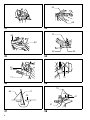
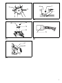
1
GB Slide Compound Saw Instruction Manual F Scie radiale Manuel d’instructions D Verbund-Tischkreissäge Betriebsanleitung I Sega composita a slitta Istruzioni per l’uso NL Radiaal-/afkortzaag Gebruiksaanwijzing E Sierra mixta deslizable Manual de instrucciones P Serra de esquadria telescópica Manual de instruções DK Kombineret afkorter-geringssav Brugsanvisning S Kap-och geringssåg Bruksanvisning N Skyvbar kombinasionssag Bruksanvisning SF Ristikelkkasaha Käyttöohje GR Ολισθαίνοντα σύνθετο πρινι Οδηγίες χρήσεως LS1013 1 3 2 1 2 4 8 7 6 9 1 5 1 10 3 4 7 8 12 11 18 13 17 15 14 16 5 6 20 21 5 7 2 19 8 23 22 9 11 24 22 26 25 27 10 31 30 28 29 32 11 12 33 38 39 34 13 36 35 37 14 3 43 40 37 41 42 15 16 43 44 45 17 18 47 46 50 48 49 32 19 20 52 53 21 4 55 54 22 51 56 58 57 23 59 23 24 60 23 25 26 27 32 61 62 64 63 62 65 28 66 67 29 30 5 m 32 68 31 32 70 32 69 36 33 35 34 40 37 72 71 35 36 73 69 11 42 30 41 41 37 6 38 74 40 75 77 76 39 40 48 48 78 32 79 41 42 81 80 43 7 Symbols The following show the symbols used for the machine. Be sure that you understand their meaning before use. Symboles Nous donnons ci-dessous les symboles utilisés pour l’outil. Assurez-vous que vous en avez bien compris la signification avant d’utiliser l’outil. Symbole Die folgenden Symbole werden für die Maschine verwendet. Machen Sie sich vor der Benutzung unbedingt mit ihrer Bedeutung vertraut. Symboli Per questo utensile vengono usati i simboli seguenti. Bisogna capire il loro significato prima di usare l’utensile. Symbolen Voor dit gereedschap worden de volgende symbolen gebruikt. Zorg ervoor dat u de betekenis van deze symbolen begrijpt alvorens het gereedschap te gebruiken. Símbolos A continuación se muestran los símbolos utilizados con esta herramienta. Asegúrese de que entiende su significado antes de usarla. Símbolos O seguinte mostra os símbolos utilizados para a ferramenta. Certifique-se de que compreende o seu significado antes da utilização. Symboler Nedenstående symboler er anvendt i forbindelse med denne maskine. Vær sikker på, at De har forstået symbolernes betydning, før maskinen anvendes. Symboler Det följande visar de symboler som används för den här maskinen. Se noga till att du förstår deras innebörd innan maskinen används. Symbolene Følgende viser de symblene som brukes for maskinen. Det er viktig å forstå betydningen av disse før maskinen tas i bruk. Symbolit Alla on esitetty koneessa käytetyt symbolit. Opettele näiden merkitys, ennen kuin käytät konetta. Σύµβολα Τα ακλουθα δείχνουν τα σύµβολα που χρησιµοποιούνται για το µηχάνηµα. Βεβαιωθείτε τι καταλαβαίνετε τη σηµασία τους πριν απ τη χρήση. 8 ❏ Read instruction manual. ❏ Lire le mode d’emploi. ❏ Bitte Betriebsanleitung lesen. ❏ Leggete il manuale di istruzioni. ❏ Lees de gebruiksaanwijzing. ❏ Lea el manual de instrucciones. ❏ Leia o manual de instruções. ❏ Læs brugsanvisningen. ❏ Läs bruksanvisningen. ❏ Les bruksanvisingen. ❏ Katso käyttöohjeita. ❏ ∆ιαβάστε τις οδηγίες χρήσης. ❏ DOUBLE INSULATION ❏ DOUBLE ISOLATION ❏ DOPPELT SCHUTZISOLIERT ❏ DOPPIO ISOLAMENTO ❏ DUBBELE ISOLATIE ❏ DOBLE AISLAMIENTO ❏ ❏ ❏ ❏ ❏ ❏ DUPLO ISOLAMENTO DOBBELT ISOLERET DUBBEL ISOLERING DOBBEL ISOLERING KAKSINKERTAINEN ERISTYS ∆ΙΠΛΗ ΜΟΝΩΣΗ ❏ When using the kerf block, always cut at the same miter angle. When changing the miter angle, use other kerf blocks. ❏ Lors de l’utilisation du plateau de dÝcoupe, effectuez toujours la coupe au même angle de coupe. Lorsque vous changez l’angle de coupe, utilisez d’autres plateaux de dÝcoupe. ❏ Bei Verwendung der Einlegeplatte immer mit demselben Gehrungswinkel schneiden. Bei einer Änderung des Gehrungswinkels sind andere Einlegeplatten zu verwenden. ❏ Usando il blocco di taglio, tagliare sempre allo stesso angolo di taglio a quartabuono. Per cambiare l’angolo di taglio a quartabuono, usare altri blocchi di taglio. ❏ Zaag altijd met dezelfde verstekhoek wanneer u het zaagsnedeblok gebruikt. Wanneer u de verstekhoek verandert, moet u een ander zaagsnedeblok gebruiken. ❏ Cuando utilice la placa de corte, corte siempre con el mismo Üngulo de inglete. Cuando cambie el Üngulo de inglete, utilice otras placas de corte. ❏ Quando utilize o bloco de corte, corte sempre com o mesmo ângulo de esquadria. Quando mudar o ângulo de esquadria, utilize outros blocos de corte. ❏ Når indlægspladen anvendes, skal der altid skæres med samme geringsvinkel. Hvis geringsvinklen ændres, skal der anvendes en anden indlægsplade. ❏ Såga alltid med samma geringsvinkel när spårklossen används. Använd andra spårklossar om du ändrar geringsvinkeln. ❏ Ved bruk av skjæreplaten, må det alltid skjæres i samme gjæringsvinkel. Når gjæringsvinkelen endres, må det brukes andre skjæreplater. ❏ Kun käytät uurroslohkoa, sahaa aina samalla kulmalla. Kun vaihdat jiirisahauskulmaa, käytä toisia uurroslohkoja. ❏ )ταν χρησιµοποιείτε το µπλοκ εγκοπής, πάντοτε να κβετε µε την ίδια γωνία κεφαλής. 9 ENGLISH Explanation of general view 1 2 3 4 5 6 7 8 9 10 11 12 13 14 15 16 17 18 19 20 21 22 23 24 25 26 27 28 Socket wrench Wrench holder Bolt Center cover Safety cover Hex bolt Arrow Blade case Shaft lock Hex bolt Saw blade Arrow Inner flange Spindle Hex bolt Saw blade Outer flange Ring 30 mm in outer diameter Dust nozzle Dust bag Fastener Kerf board Knob Carbide tip Left bevel cut Straight cut Right bevel cut Adjusting bolt 29 30 31 32 33 34 35 36 37 38 39 40 41 42 43 44 45 46 47 48 49 50 51 52 53 54 55 56 Turn base Top surface of turn base Periphery of blade Guide fence Lock pin Grip Pointer Miter scale Lever Loosen Tighten Arm Pointer Bevel scale Sub-fence Sub-fence R Screws Vise arm Vise rod Screw Clamp screw Support Turn base Vise plate Vise nut Vise knob Holder Lock-off button 57 58 59 60 61 62 63 64 65 66 67 68 69 70 71 72 73 74 75 76 77 78 79 80 81 Handle Switch trigger Lever Apply pressure in parallel with blade Vise Spacer block Aluminum extrusion Adjusting screw Stopper arm Cut grooves with blade Stopper pin Hex bolts Triangular rule Screw Hex bolt Hex bolt Screws Arm holder Right 45° bevel angle adjusting bolt Left 45° bevel angle adjusting bolt Hex lock nut Kerf block Limit mark Brush holder cap Screwdriver SPECIFICATIONS Model LS1013 Blade diameter .................................................................................................................................. 250 mm — 260 mm Hole diameter ........................................................................................................................................................ 30 mm Max. cutting capacities (H x W) with blade 260 mm in diameter Bevel angle Miter angle 45° (left) 0° 45° (right) 0° 50 mm x 310 mm 91 mm x 310 mm 31 mm x 310 mm 45° (left and right) 50 mm x 220 mm 91 mm x 220 mm 31 mm x 220 mm — 91 mm x 190 mm — 52° (right) –1 No load speed (min ) ............................................................................................................................................ 3,700 Dimensions (L x W x H) ..................................................................................................... 760 mm x 520 mm x 625 mm Net weight ...............................................................................................................................................................21 kg • Due to our continuing program of research and development, the specifications herein are subject to change without notice. • Note: Specifications may differ from country to country. Power supply The tool should be connected only to a power supply of the same voltage as indicated on the nameplate, and can only be operated on single-phase AC supply. They are double-insulated in accordance with European Standard and can, therefore, also be used from sockets without earth wire. Safety hints For your own safety, please refer to the enclosed safety instructions. 10 ADDITIONAL SAFETY RULES 1. 2. 3. 4. 5. 6. 7. Wear eye protection. Do not operate saw without guards in place. Don’t use the tool in the presence of flammable liquids or gases. Check the blade carefully for cracks or damage before operation. Replace cracked or damaged blade immediately. Use only flanges specified for this tool. Be careful not to damage the arbor, flanges (especially the installing surface) or bolt. Damage to these parts could result in blade breakage. Make sure that the turn base is properly secured so it will not move during operation. 8. 9. 10. 11. 12. 13. 14. 15. 16. 17. 18. 19. 20. 21. 22. 23. 24. 25. 26. 27. 28. 29. For your safety, remove the chips, small pieces, etc. from the table top before operation. Avoid cutting nails. Inspect for and remove all nails from the workpiece before operation. Make sure the shaft lock is released before the switch is turned on. Be sure that the blade does not contact the turn base in the lowest position. Hold the handle firmly. Be aware that the saw moves up or down slightly during start-up and stopping. Do not perform any operation freehand. The workpiece must be secured firmly against the turn base and guide fence with the vise during all operations. Never use your hand to secure the workpiece. Keep hands out of path of saw blade. Avoid contact with any coasting blade. It can still cause severe injury. Never reach around saw blade. Make sure the blade is not contacting the workpiece before the switch is turned on. Before using the tool on an actual workpiece, let it run for a while. Watch for vibration or wobbling that could indicate poor installation or a poorly balanced blade. Wait until the blade attains full speed before cutting. Stop operation immediately if you notice anything abnormal. Do not attempt to lock the trigger in the ON position. Shut off power and wait for saw blade to stop before servicing or adjusting tool. Be alert at all times, especially during repetitive, monotonous operations. Don’t be lulled into a false sense of security. Blades are extremely unforgiving. Always use accessories recommended in this manual. Use of improper accessories such as abrasive wheels may cause an injury. Don’t abuse cord. Never yank cord to disconnect it from the receptacle. Keep cord away from heat, oil, water and sharp edges. Do not use the saw to cut other than aluminum, wood or similar materials. Connect slide compound saws to a dust collecting device when sawing. Select saw blades in relation to the material to be cut. Take care when slotting. Replace the kerf board when worn. SAVE THESE INSTRUCTIONS. OPERATING INSTRUCTIONS Socket wrench (Fig. 1) The socket wrench is stored as shown in Fig. 1. When using the socket wrench, pull it out of the wrench holder. After using the socket wrench, return it to the wrench holder. Installing or removing saw blade Important: Always be sure that the tool is switched off and unplugged before installing or removing the blade. Use the socket wrench to loosen the hex bolt holding the center cover by turning it counterclockwise. Raise the safety cover and center cover. (Fig. 3) Press the shaft lock to lock the spindle and use the socket wrench to loosen the hex bolt clockwise. Then remove the hex bolt, outer flange and blade. (Fig. 4) Mount the blade onto the spindle, making sure that the direction of the arrow on the surface of the blade matches the direction of the arrow on the blade case. (Fig. 5) CAUTION: The ring 30 mm in outer diameter is factory-installed between the inner and outer flanges. (Fig. 6) Install the outer flange and hex bolt, and then use the socket wrench to tighten the hex bolt securely counterclockwise while pressing the shaft lock. Then tighten the hex bolt clockwise to secure the center cover. CAUTION: Use only the Makita socket wrench provided to install or remove the blade. Failure to do so may result in overtightening or insufficient tightening of the hex bolt. This could cause an injury. To remove the blade, raise the safety cover and center cover. Loosen the hex bolt using the socket wrench and remove the hex bolt, outer flange and blade. Safety cover (Fig. 7) When lowering the handle, the safety cover rises automatically. The cover returns to its original position when the cut is completed and the handle is raised. NEVER DEFEAT OR REMOVE THE SAFETY COVER. In the interest of your personal safety, always maintain the safety cover in good condition. Any irregular operation of the safety cover should be corrected immediately. NEVER USE THE TOOL WITH A FAULTY SAFETY COVER. If the see-through safety cover becomes dirty, or sawdust adheres to it in such a way that the blade and/or workpiece is no longer easily visible, unplug the saw and clean the cover carefully with a damp cloth. Do not use solvents or any petroleum-based cleaners on the plastic cover. Dust bag (Fig. 8) The use of the dust bag makes cutting operations clean and dust collection easy. To attach the dust bag, insert the dust nozzle into the dust spout on the blade case and fit the bag’s entry port over the dust nozzle. When the dust bag is about half full, remove the dust bag from the tool and pull the fastener out. Empty the dust bag of its contents, tapping it lightly so as to remove particles adhering to the insides which might hamper further collection. NOTE: If you connect a vacuum cleaner to your saw, more efficient and cleaner operations can be performed. Bench mounting saw (Fig. 2) This tool should be bolted with four bolts to a level and stable surface using the bolt holes provided in the tool’s base. This will help prevent tipping and possible injury. 11 Positioning kerf board (Fig. 9 & 10) This tool is provided with the kerf boards in the turn base. The kerf boards are factory adjusted so that the saw blade does not contact the kerf boards. Before use, adjust the kerf boards as follows: First, unplug the tool. Loosen all the screws (2 each on left and right) securing the kerf boards. Re-tighten them to the extent that the kerf boards can be easily moved by hand. Loosen the knob which secures the slide poles. Pull the carriage toward you fully and lower the handle. Adjust the kerf boards so that the kerf boards just contact the side of blade teeth slightly. Tighten the front screws (do not tighten firmly). Push the carriage toward the guide fence fully and adjust the kerf boards so that the kerf boards just contact the sides of blade teeth slightly. Tighten the rear screws (do not tighten firmly). After adjusting the kerf boards, raise the handle. Then tighten all the screws securely. CAUTION: After changing the bevel angle, always readjust the kerf boards as described above. Maintaining maximum cutting capacity (Fig. 11 & 12) Unplug the tool before any adjustment is attempted. This tool is factory adjusted to provide the max. cutting capacity for a 255 mm saw blade. When the diameter of the blade has been reduced due to sharpening, adjust the lower limit position of the blade as follows: Push the carriage toward the guide fence fully and lower the handle completely. Use the socket wrench to turn the adjusting bolt until the periphery of the blade extends slightly below the top surface of the turn base at the point where the front face of the guide fence meets the top surface of the turn base. With the tool unplugged, rotate the blade by hand while holding the handle all the way down to be sure that the blade does not contact any part of the lower base. Re-adjust slightly, if necessary. CAUTION: After installing a new blade, always be sure that the blade does not contact any part of the lower base when the handle is lowered completely. Always do this with the tool unplugged. Positioning for adjusting the miter angle (Fig. 13) Loosen the grip by turning counterclockwise. Turn the turn base while pressing down the lock pin. When you have moved the grip to the position where the pointer indicates the desired angle on the miter scale, securely tighten the grip clockwise. CAUTION: • When turning the turn base, be sure to raise the handle fully. • After changing the miter angle, always secure the turn base by tightening the grip firmly. Positioning for adjusting the bevel angle (Fig. 14 & 15) The saw blade tilts up to 45° to the left and right. To adjust the bevel angle, loosen the lever at the rear of the tool. Unlock the arm by pushing the handle rather firmly in the direction that you intend to tilt the saw blade. Tilt the saw blade until the pointer points to the desired angle on the bevel scale. Tighten the lever to secure the arm. 12 CAUTION: • When tilting the saw blade, be sure to raise the handle fully. • After changing the bevel angle, always secure the arm by tightening the lever. • When changing bevel angles, be sure to position the kerf boards appropriately as explained in the “Positioning kerf boards” section. Sub-fence (Fig. 16 & 17) This tool is equipped with the sub-fence which should ordinarily be positioned as shown in Fig. 16. However, when performing left bevel cuts, set it to the left position as shown in Fig. 17. Sub-fence (R) (Fig. 18) The sub-fence R should ordinarily be installed on the right side of the guide fence. Insert the rods of the subfence R into the holes in the guide fence. Tighten the screws to secure the sub-fence R. CAUTION: When performing right bevel cuts, never use the subfence R. It will contact the blade or some part of the tool, causing a serious injury to operator. Securing workpiece WARNING: It is extremely important to always secure the workpiece properly and tightly with the vise. Failure to do so can cause the tool to be damaged and/or the workpiece to be destroyed. PERSONAL INJURY MAY ALSO RESULT. Also, after a cutting operation, DO NOT raise the blade until the blade has come to a complete stop. 1. Vertical vise (Fig. 19) The vertical vise can be installed in two positions on either the left or right side of the guide fence or the base. Insert the vise rod into the hole in the guide fence or the base and tighten the screw on the back of the guide fence to secure the vise rod. Position the vise arm according to the thickness and shape of the workpiece and secure the vise arm by tightening the clamp screw. If the screw to secure the vise arm contacts the guide fence, install the vertical vise on the base, using the hole in the base. Make sure that no part of the tool contacts the vise when lowering the handle fully or when pulling or pushing the carriage. CAUTION: The workpiece must be secured firmly against the turn base and guide fence with the vise during all operations. If some parts contacts the vise, re-position the vise arm. Press the workpiece flat against the guide fence and the turn base. Position the workpiece at the desired cutting position and secure it firmly by tightening the clamp screw of the vise. CAUTION: When cutting long workpieces, use supports that are as high as the top surface level of the turn base. (Fig. 20) 2. 3. Horizontal vise (optional accessory) (Fig. 21) The horizontal vise can be installed in two positions on either the left or right side of the base. When performing 15° or greater miter cuts, install the horizontal vise on the side opposite the direction in which the turn table is to be turned. By flipping the vise nut to the left, the vise is released, and rapidly moves in and out. To grip workpieces, push the vise knob forward until the vise plate contacts the workpiece and flip the vise nut to the right. Then turn the vise knob clockwise to secure the workpiece. The maximum width of workpieces which can be secured by the horizontal vise is 200 mm. When installing the horizontal vise on the right side of the base, also use the sub- fence R to secure the workpiece more firmly. Refer to the “Sub-fence (R)” for installing the subfence R. 1. CAUTION: Always set the vise nut to the right fully when securing the workpiece. Failure to do so may result in insufficient securing of the workpiece. This could cause the workpiece to be thrown, cause damage to the blade or cause the dangerous loss of control of the tool. Holders (Fig. 22) The holders can be installed on either side as a convenient means of holding workpieces horizontally. Slip the holder rods into the holes in the base and adjust their length according to the workpiece to be held. Then tighten the holders securely with the screws. 2. Switch action (Fig. 23) CAUTION: • Before plugging in the tool, always check to see that the switch trigger actuates properly and returns to the “OFF” position when released. • When not using the tool, remove the lock-off button and store it in a secure place. This prevents unauthorized operation. • Do not pull the trigger hard without pressing in the lockoff button. This can cause switch breakage. To prevent the trigger from being accidentally pulled, a lock-off button is provided. To start the tool, push the lever to the left, press in the lock-off button and then pull the trigger. Release the trigger to stop. Operation CAUTION: • Before use, be sure to release the handle from the lowered position by pulling the stopper pin. • Make sure the blade is not contacting the workpiece, etc. before the switch is turned on. • Do not apply excessive pressure on the handle when cutting. Too much force may result in overload of the motor and/or decreased cutting efficiency. • Gently press down the handle to perform the cut. If the handle is pressed down with force or if lateral force is applied, the blade will vibrate and leave a mark (saw mark) in the workpiece and the precision of the cut will be impaired. • During a slide cut, gently push the carriage toward the guide fence without stopping. If the carriage movement is stopped during the cut, a mark will be left in the workpiece and the precision of the cut will be impaired. 3. 4. Press cutting (cutting small workpieces) (Fig. 24) • Workpieces up to 91 mm high and 70 mm wide can be cut in the following way. • Push the carriage toward the guide fence fully and tighten the knob to secure the carriage. Secure the workpiece with the vise. Switch on the tool and wait until the blade attains full speed before lowering gently into the cut. When the cut is completed, switch off the tool and WAIT UNTIL THE BLADE HAS COME TO A COMPLETE STOP before returning the blade to its fully elevated position. CAUTION: Firmly tighten the clamp screw on the turn base so that the carriage will not move during operation. Insufficient tightening may cause unexpected kickback of the blade. Possible serious injury may result. Slide (push) cutting (cutting wide workpieces) (Fig. 25) • Workpieces up to 91 mm high and 305 mm wide can be cut in the following way. • Loosen the knob so that the carriage can slide freely. Pull the carriage toward you fully. Switch on the tool and wait until the blade attains full speed. Press down the handle and PUSH THE CARRIAGE TOWARD THE GUIDE FENCE TO CUT THE WORKPIECE. When the cut is completed, switch off the tool and WAIT UNTIL THE BLADE HAS COME TO A COMPLETE STOP before returning the blade to its fully elevated position. CAUTION: • Whenever performing the slide cut, FIRST PULL THE CARRIAGE TOWARD YOU FULLY and press down the handle to the fully lowered position, then PUSH THE CARRIAGE TOWARD THE GUIDE FENCE. If you perform the slide cut without pulling the carriage fully or if you perform the slide cut toward your direction, the blade may kick back unexpectedly with the potential to cause serious injury. • Never perform the slide cut with the handle locked in the lowered position by pressing the stopper pin. Miter cutting Refer to the previously covered “Positioning for adjusting the miter angle”. Bevel cut (Fig. 26) • Left and right 0° – 45° bevel cuts can be performed. At a left 45° bevel angle, workpieces up to 50 mm high and 305 mm wide can be cut. At a right 45° bevel angle, workpieces up to 31 mm high and 305 mm wide can be cut. • Loosen the lever and tilt the saw blade to set the bevel angle. Be sure to re-tighten the lever firmly to secure the selected bevel angle safely. Secure the workpiece with a vise. Switch on the tool and wait until the blade attains full speed. Then gently lower the handle to the fully lowered position while applying pressure in parallel with the blade and PUSH THE CARRIAGE TOWARD THE GUIDE FENCE TO CUT THE WORKPIECE. When the cut is completed, switch off the tool and WAIT UNTIL THE BLADE HAS COME TO A COMPLETE STOP before returning the blade to its fully elevated position. 13 5. 6. 7. CAUTION: • During a bevel cut, it may create a condition whereby the piece cut off will come to rest against the side of the blade. If the blade is raised while the blade is still rotating, this piece may be caught by the blade, causing fragments to be scattered around which is dangerous. The blade should be raised ONLY after the blade has come to a complete stop. • When pressing down the handle, apply pressure in parallel with the blade. If a force is applied perpendicularly to the turn base or if the pressure direction is changed during a cut, the precision of the cut will be impaired. Compound cutting Compound cutting is the process in which a bevel angle is made at the same time in which a miter angle is being cut on a workpiece. Compound cutting can be performed at angle shown in the table below. Miter angle Bevel angle Left 0° – 47° and right 0° – 45° Left and right 0° – 45° Right 52° Left 0° – 40° and right 0° – 45° At the miter angle of left and right 45° and bevel angle of left 45°, workpieces up to 50 mm high and 215 mm wide can be cut. At the miter angle of left and right 45° and bevel angle of right 45°, workpieces up to 31 mm high and 215 mm wide can be cut. When performing compound cutting, refer to “Press cutting”, “Slide cutting”, “Miter cutting” and “Bevel cut” explanations. Cutting aluminum extrusion (Fig. 27) When securing aluminum extrusions, use spacer blocks or pieces of scrap as shown in Fig. 27 to prevent deformation of the aluminum. Use a cutting lubricant when cutting the aluminum extrusion to prevent build-up of the aluminum material on the blade. CAUTION: Never attempt to cut thick or round aluminum extrusions. Thick aluminum extrusions may come loose during operation and round aluminum extrusions cannot be secured firmly with this tool. Groove cutting (Fig. 28 & 29) A dado type cut can be made by proceeding as follows: Adjust the lower limit position of the blade using the adjusting screw on the stopper arm to limit the cutting depth of the blade. To adjust it, rotate the stopper arm to the position shown in Fig. 28. Adjust the adjusting screw so that the blade stops at the desired position when lowering the handle fully. After adjusting the lower limit position of the blade, cut parallel grooves across the width of the workpiece using a slide (push) cut as shown in Fig. 29. Then remove the workpiece material between the grooves with a chisel. Do not attempt to perform this type of cut using wide (thick) blades or with a dado blade. Possible loss of control and injury may result. CAUTION: Be sure to return the stopper arm to the original position when performing other than groove cutting. 14 Carrying tool (Fig. 30 & 31) Make sure that the tool is unplugged. Secure the blade at 0° bevel angle and the turn base at 52° miter angle to the right. Secure the slide poles after pulling the carriage toward you fully. Lower the handle fully and lock it in the lowered position by pushing in the stopper pin. Carry the tool by holding both sides of the tool base as shown in Fig. 31. If you remove the holders, dust bag, vise, etc., you can carry the tool more easily. CAUTION: Always secure all moving portions before carrying the tool. MAINTENANCE CAUTION: Always be sure that the tool is switched off and unplugged before carrying out any work on the tool. Adjusting the cutting angle This tool is carefully adjusted and aligned at the factory, but rough handling may have affected the alignment. If your tool is not aligned properly, perform the following: 1) Miter angle Push the carriage toward the guide fence and tighten the knob to secure the carriage. Loosen the grip which secures the turn base. Turn the turn base so that the pointer indicates 0° on the miter scale. Then turn the turn base slightly clockwise and counterclockwise to seat the turn base cozily in the 0° miter notch. (Leave as it is if the pointer does not indicate 0°.) Loosen the four hex bolts securing the guide fence using the socket wrench. (Fig. 32) Lower the handle fully and lock it in the lowered position by pushing in the lock pin. Square the side of the blade with the face of the guide fence using a triangular rule, try-square, etc. Then securely tighten the hex bolts on the guide fence in the order from the left side. (Fig. 33) Make sure that the pointer indicates 0° on the miter scale. If the pointer does not indicate 0°, loosen the screw securing the pointer and adjust the pointer. (Fig. 34) 2) Bevel angle i) 0° bevel angle Push the carriage toward the guide fence and tighten the knob to secure the slide poles. Lower the handle fully and lock it in the lowered position by pushing in the lock pin. Loosen the lever at the rear of the tool. Make sure that the arm is locked. (Fig. 35) Turn the hex bolt on the left side of the arm two or three revolutions counterclockwise. Turn the hex bolt on the right side of the arm two or three revolutions counterclockwise to tilt the blade to the left. (Fig. 36) Carefully square the side of the blade with the top surface of the turn base using the triangular rule, try-square, etc. by turning the hex bolt on the right side of the arm clockwise. Turn the hex bolt on the left side of the arm clockwise as far as it will go. Then tighten the lever securely. (Fig. 37) Make sure that the two pointers on the arm point to each 0° on the bevel scale on the arm holder. If they do not point to 0°, loosen the screws which secure the pointers and adjust them so that they will point to 0°. (Fig. 38) ii)45° bevel angle Adjust the 45° bevel angle only after performing 0° bevel angle adjustment. To adjust left 45° bevel angle, loosen the lever and tilt the blade 45° to the left. Make sure that the pointer on the arm holder points to 45° on the bevel scale on the arm holder. If the pointer does not point to 45°, turn the left 45° bevel angle adjusting bolt on the side of the arm holder until the pointer points to 45°. To adjust right 45° bevel angle, perform the same procedure described above. (Fig. 39) Adjusting for smooth beveling action (Fig. 40) The hex lock nut holding together the arm and arm holder has been factory adjusted to assure smooth beveling action and to guarantee precise cutting. Do not tamper with it. Should looseness develop at the arm and arm holder connection, tighten the hex lock nut using a wrench. ACCESSORIES CAUTION: These accessories or attachments are recommended for use with your Makita tool specified in this manual. The use of any other accessories or attachments might present a risk of injury to persons. Only use accessory or attachment for its stated purpose. If you need any assistance for more details regarding these accessories, ask your local Makita service center. • • • • • • • • • Dust bag Socket wrench 13 Sub-fence R Triangular rule Lock-off button Vise assembly (horizontal vise) Vertical vise Elbow Kerf block Kerf block (Standard accessory for European countries) (Fig. 41) CAUTION: • When using the kerf block, always cut at the same miter angle. • When changing the miter angle, use other kerf blocks. • When performing bevel cuts, never use the kerf block. Failure to do so splits the block, causing a serious injury to operator. When you use the kerf block at 90° cutting, you can splinter-free cut in workpiece on the side of the guide fence (height of the workpiece is up to 35 mm). Install the kerf block onto the guide fence by means of the two screws. (Adjust the guide fence and the kerf block so that they contact their faces. Then tighten the screws securely.) Replacement of carbon brushes (Fig. 42 & 43) Replace carbon brushes when they are worn down to the limit mark. Both identical carbon brushes should be replaced at the same time. After use • After use, wipe off chips and dust adhering to the tool with a cloth or the like. Keep the safety cover clean according to the directions in the previously covered “Safety cover”. Lubricate the sliding portions with tool oil to prevent rust. • When storing the tool, pull the carriage toward you fully so that the slide pole is thoroughly inserted into the turn base. To maintain product safety and reliability, repairs, maintenance or adjustment should be carried out by a Makita Authorized Service Center. 15 FRANÇAIS Descriptif 1 2 3 4 5 6 7 8 9 10 11 12 13 14 15 16 17 18 19 20 21 22 23 24 25 26 27 28 29 Clé à douille Porte-clé Boulon Capot central Carter de sécurité Boulon hexagonal Flèche Carter de lame Blocage de l’arbre Boulon hexagonal Lame de scie Flèche Flasque intérieur Axe Boulon hexagonal Lame de scie Flasque extérieur Bague de 30 mm de diamètre extérieur Buse du sac Sac à poussière Barrette Plateau de découpe Bague Dent carbure Coupe oblique à gauche Coupe droite Coupe oblique à droite Boulon de réglage Socle rotatif 30 Surface supérieure du socle rotatif 31 Périphérie de la lame 32 Guide 33 Goupille de verrouillage 34 Poignée 35 Index 36 Secteur 37 Levier 38 Desserrer 39 Serrer 40 Support 41 Index 42 Echelle 43 Butée réglable 44 Butée amovible 45 Vis 46 Bras de l’étau 47 Tige de l’étau 48 Vis 49 Poignée de serrage 50 Support 51 Socle rotatif 52 Plaque d’étau 53 Ecrou de l’étau 54 Bouton de l’étau 55 Servante 56 Bouton de sécurité 57 Poignée 58 Gâchette 59 Levier 60 La poignée doit être manœuvrée selon un plan parallèle à celui occupé par la lame 61 Etau 62 Martyr 63 Profilé d’aluminium 64 Vis de réglage 65 Bras de butée 66 Coupe de rainures avec la lame 67 Verrouillage du bras 68 Boulons hexagonaux 69 Equerre 70 Vis 71 Boulon hexagonal 72 Boulon hexagonal 73 Vis 74 Support des coulisses 75 Boulon de réglage de l’angle de biseau de 45° à droite 76 Boulon de réglage de l’angle de biseau de 45° à gauche 77 Ecrou “nylstop” 78 Plateau de découpe 79 Limite d’usure 80 Bouchon du porte-charbon 81 Tournevis SPECIFICATIONS Modèle LS1013 Diamètre de lame .............................................................................................................................. 250 mm — 260 mm Alésage ................................................................................................................................................................. 30 mm Capacités max. de coupe (H x l) avec lame de 260 mm de diamètre Coupe en biseau Coupe d’onglet 45° (gauche) 0° 45° (droite) 0° 50 mm x 310 mm 91 mm x 310 mm 31 mm x 310 mm 45° (gauche et droite) 50 mm x 220 mm 91 mm x 220 mm 31 mm x 220 mm — 91 mm x 190 mm — 52° (droite) Vitesse à vide (t/mn) ................................................................................................................................................ 3 700 Dimensions (L x l x H) ..........................................................................................................760 mm x 520 mm x 625 mm Poids net ................................................................................................................................................................. 21 kg • Etant donné l’évolution constante de notre programme de recherche et de développement, les spécifications contenues dans ce manuel sont sujettes à modification sans préavis. • Note : Les spécifications peuvent varier suivant les pays. Alimentation L’outil ne devra être raccordé qu’à une alimentation de la même tension que celle qui figure sur la plaque signalétique, et il ne pourra fonctionner que sur un courant secteur monophasé. Réalisé avec une double isolation, il est conforme à la réglementation européenne et peut de ce fait être alimenté sans mise à la terre. Consignes de sécurité Pour votre propre sécurité, reportez-vous aux consignes de sécurité qui accompagnent l’outil. 16 CONSIGNES DE SECURITE SUPPLEMENTAIRES 1. 2. 3. 4. 5. 6. 7. 8. 9. 10. 11. 12. 13. 14. 15. 16. 17. 18. 19. 20. 21. 22. 23. 24. Portez une protection oculaire. N’utilisez jamais votre outil sans les protections en place. Ne vous servez pas de votre outil en présence de gaz ou de liquides inflammables. Avant de scier, vérifiez attentivement que la lame n’est ni endommagée, ni fendue. Si tel était le cas, changez-la immédiatement. N’utilisez que les flasques spécifiés pour cet outil. Veillez à ne pas endommager l’arbre, les flasques (surtout leur face d’appui) ni le boulon, ce qui pourrait entraîner la rupture de la lame. Assurez-vous que le socle rotatif est correctement fixé de façon qu’il ne bouge pas pendant le sciage. Pour votre sécurité, retirez copeaux ou autres fragments de la surface du plateau avant d’opérer. Evitez les clous ; avant de scier, examinez l’élément à scier et retirez-en tous les clous. Assurez-vous que le blocage de l’arbre est libéré avant de mettre le contact. Assurez-vous que la lame ne touche pas le socle rotatif quand elle est abaissée au maximum. Tenez le bras fermement. Tenez compte du fait que la scie se déplace légèrement de haut en bas au démarrage et à l’arrêt. Ne sciez jamais à la volée. Le matériau doit être fermement immobilisé sur le socle rotatif, et en appui contre la butée, quelque soit le type de coupe. Ne maintenez jamais la pièce avec la main. Gardez bien les mains à l’écart de la lame. Evitez tout contact avec une lame “en roue libre” ; vous pourriez vous blesser gravement. Ne mettez jamais les mains à portée de la lame. Assurez-vous que la lame ne touche pas l’élément à scier avant de mettre le contact. Avant de scier, faites tourner l’outil un instant à vide. Vérifiez que la lame ne présente ni balourd ni shimmy qui pourraient résulter d’un montage incorrect ou d’une usure irrégulière. Avant de scier, attendez que la lame ait atteint sa pleine vitesse. Arrêtez immédiatement le sciage si vous remarquez quoi que ce soit d’anormal. Ne tentez pas de maintenir la gâchette en position ON. Coupez le courant et attendez l’arrêt de la lame avant de réparer ou de régler votre outil. Restez vigilant, surtout durant les sciages répétés et monotones. Ne vous laissez jamais prendre par un sentiment trompeur de sécurité. Les lames de scie ne pardonnent pas. N’utilisez que les accessoires recommandés dans le catalogue Makita. L’utilisation d’accessoires différents, disques à tronçonner notamment, entraîne des risques de blessure. Ne maltraitez pas le câble. Ne tirez pas dessus pour débrancher. Maintenez-le à l’écart de la chaleur, des corps gras, de l’eau et des arêtes coupantes. 25. N’utilisez pas la scie pour couper autre chose que de l’aluminium, du bois ou des matériaux similaires. 26. Pendant la coupe, raccordez les scies à coupe d’onglet à un dispositif de ramassage de la poussière. 27. Sélectionnez les lames en fonction du matériau à couper. 28. Prudence lorsque vous taillez des encoches. 29. Remplacez le plateau de découpe quand il est usé. CONSERVEZ CES INSTRUCTIONS. MODE D’EMPLOI Clé à douille (Fig. 1) La clé à douille est rangée comme indiqué sur la Fig. 1. Pour utiliser la clé à douille, sortez-la du porte-clé. Quand vous avez fini de vous en servir, remettez-la dans le porte-clé. Montage sur établi (Fig. 2) Cet outil doit être fixé à l’aide de quatre boulons sur une surface plate et stable grâce aux pattes perforées que comporte sa base. Ceci afin d’éviter qu’il se renverse et provoque des blessures. Pose et dépose de la lame Important : Assurez-vous toujours que le contact est coupé et l’outil débranché avant de retirer ou d’installer la lame. Relâchez le boulon hexagonal qui maintient le capot central en le dévissant – vers la gauche. Soulevez le carter de sécurité et le capot central. (Fig. 3) Appuyez sur le blocage de l’arbre de façon que la lame ne puisse pas tourner, et servez-vous de la clé à douille pour desserrer – vers la droite – le boulon hexagonal. Retirez ensuite ce boulon, le flasque extérieur et la lame. (Fig. 4) Pour installer la lame, montez-la sur l’axe en vous assurant que le sens de la flèche portée sur la lame correspond à celui de la flèche du carter de lame. (Fig. 5) ATTENTION : La bague de 30 mm de diamètre extérieur a été montée en usine entre les flasques intérieur et extérieur. (Fig. 6) Installez le flasque extérieur et le boulon hexagonal, puis, à l’aide de la clé à douille, serrez à fond le boulon hexagonal en tournant vers la gauche tout en maintenant le blocage de l’arbre. Serrez ensuite le boulon hexagonal vers la droite pour fixer le capot central. ATTENTION : Ne vous servez que de la clé à douille Makita fournie avec l’outil pour installer ou démonter la lame ; faute de quoi vous risquez de serrer ou trop ou pas assez le boulon hexagonal et d’avoir un accident grave. Pour retirer la lame, soulevez le carter de sécurité et le capot central. Desserrez le boulon hexagonal avec la clé à douille, puis retirez le boulon hexagonal, le flasque extérieur et la lame. 17 Carter de sécurité (Fig. 7) Lorsque vous abaissez le bras, le carter de sécurité s’efface automatiquement. Une fois la coupe terminée et le bras relevé, il revient à sa position d’origine. NE TENTEZ JAMAIS D’ENTRAVER LE LIBRE JEU DU CARTER DE SÉCURITÉ ; NE LE DEMONTEZ PAS POUR TRAVAILLER. Pour votre sécurité personnelle, vous devez le maintenir en bon état de marche. Tout fonctionnement anormal du carter de sécurité devra être immédiatement corrigé. N’UTILISEZ JAMAIS VOTRE SCIE AVEC UN CARTER DE SECURITE FONCTIONNANT IMPARFAITEMENT. Si le carter de sécurité transparent se salit ou si la sciure y adhère de façon que la lame et/ou l’élément à scier ne soient plus visibles, débranchez l’outil et nettoyez-le soigneusement à l’aide d’un chiffon humide. N’utilisez pas de solvants ni de détergents à base d’essence. Sac à poussière (Fig. 8) L’utilisation du sac à poussière garantit un travail propre et facilite le ramassage des poussières. Pour le fixer sur la scie, introduisez la buse dans la goulotte d’éjection poussière du carter de lame et adaptez l’orifice du sac à l’autre extrémité de la buse. Dès que le sac à poussière est à moitié plein, retirez-le de l’outil et tirez sur la barrette. Videz le sac, et tapotez-le légèrement pour en détacher les poussières restées collées sur la paroi intérieure. NOTE : Si vous raccordez un aspirateur à votre outil, vous obtiendrez un meilleur rendement et un travail plus propre. Installation des plateaux de découpe (Fig. 9 et 10) Cet outil est muni de deux plateaux de découpe incorporés dans le socle rotatif. Ces plateaux ont été réglés en usine de façon que la lame n’entre pas en contact avec eux. Avant l’utilisation, réglez les plateaux de découpe comme suit : Commencez par débrancher l’outil. Puis, desserrez toutes les vis (2 à droite et 2 à gauche) de fixation des plateaux. Resserrez-les de façon que les plateaux de découpe puissent facilement bouger à la main. Desserrez le bouton de fixation des tiges de coulissage. Déplacez complètement le chariot vers vous et abaissez le bras. Réglez les plateaux de découpe de façon qu’ils touchent juste l’arête des dents de la lame. Serrez les vis avant (sans excès). Déplacez complètement le chariot vers le guide et réglez les plateaux de découpe de façon qu’ils touchent juste l’arête des dents de la lame. Serrez les vis arrière (sans excès). Lorsque les plateaux de découpe sont réglés, relevez le bras. Puis serrez toutes les vis à fond. ATTENTION : Quand vous modifiez l’angle de biseau, reprenez toujours le réglage des plateaux de découpe comme indiqué ci-dessus. Pour obtenir un rendement maximum (Fig. 11 et 12) Débranchez l’outil avant toute opération de réglage. L’outil a été réglé en usine de façon à fournir son rendement optimum avec une lame de 255 mm. Lorsque ce diamètre s’est trouvé réduit par affûtage, réglez la limite inférieure de la lame comme suit : Repoussez le chariot à fond vers la butée et abaissez complètement le bras. A l’aide de la clé à douille, tournez le bouton de réglage jusqu’à ce que la périphérie de la lame se trouve légèrement en-dessous de la surface supérieure du socle rotatif au point où la face avant du guide rencontre la surface supérieure du socle. L’outil étant débranché, tournez la lame à la main en maintenant le bras complètement abaissé pour vous assurer que la lame ne touche aucune partie du socle rotatif. Le cas échéant, affinez le réglage. ATTENTION : Lorsque vous installez une lame neuve, vérifiez toujours que la lame ne touche aucune partie du socle inférieur lorsque le bras est complètement abaissé. Effectuez toujours cette vérification l’outil débranché. Installation pour le réglage de la coupe d’onglet (Fig. 13) Relâchez la poignée en la tournant vers la gauche. Tournez le socle rotatif en appuyant sur la goupille de verrouillage. Lorsque la poignée est arrivée au point où l’index se trouve face à la valeur angulaire voulue sur le secteur, serrez à fond la poignée en la tournant vers la droite. ATTENTION : • Lorsque vous tournez le socle rotatif, veillez à bien relever le bras à fond. • Après avoir modifié l’angle de coupe, fixez toujours le socle rotatif en tournant la poignée à fond. Installation pour le réglage de l’angle de biseau (Fig. 14 et 15) La lame de scie se relève de 45° sur la gauche et sur la droite. Pour régler l’angle de biseau, desserrez le levier au dos de l’outil. Déverrouillez le support puis orientez énergiquement le bras dans le sens dans lequel vous voulez incliner la lame. Inclinez la lame jusqu’à ce que l’index se trouve en face de la valeur angulaire voulue sur l’échelle. Puis resserrez le levier pour fixer la lame. ATTENTION : • Quand vous inclinez la lame, veillez bien à relever le bras à fond. • Après avoir modifié l’angle de biseau, fixez toujours le support en serrant le levier. • Quand vous modifiez l’angle de biseau, veillez à réinstallez les plateaux de découpe comme expliqué dans la section “Installation des plateaux de découpe”. Butée réglable (Fig. 16 et 17) L’outil est muni d’une butée réglable qui sera normalement installée comme indiqué à la Fig. 16. Toutefois, pour effectuer des coupes obliques à gauche, orientez-la à gauche comme indiqué sur la Fig. 17. Butée (D) amovible (Fig. 18) La butée amovible s’installe généralement sur le côté opposé (droit) du guide. Introduisez les pieds de la butée dans les orifices aménagés dans le guide. Serrez les vis pour immobiliser la butée (D) amovible. 18 ATTENTION : N’utilisez jamais la butée (D) amovible pour effectuer des coupes obliques à droite. Elle entrerait en contact avec la lame ou toute autre partie de l’outil, ce qui pourrait vous blesser gravement. Serrage des pièces AVERTISSEMENT : Il est extrêmement important de bien toujours fixer en place, correctement et fermement, les pièces à scier à l’aide de l’étau. Faute de cette précaution, vous risquez d’endommager votre scie et la pièce. VOUS RISQUEZ AUSSI DE VOUS BLESSER. Après avoir terminé votre coupe, NE RELEVEZ PAS LA LAME tant qu’elle n’est pas arrivée à un arrêt complet. 1. Etau vertical (Fig. 19) L’étau vertical s’installe sur deux positions au choix : à gauche ou à droite du guide ou du socle rotatif. Insérez la tige de l’étau dans l’orifice du guide ou du socle, et serrez la vis au dos du guide pour fixer la tige de l’étau. Placez le bras de l’étau en fonction de l’épaisseur et de la forme de la pièce à couper, et fixez le bras de l’étau en serrant l’écrou à oreilles. Si la vis du bras de l’étau touche le guide, installez l’étau vertical sur le socle, à l’aide de l’orifice situé dans le socle. Assurez-vous qu’aucune partie de l’outil ne touche l’étau lorsque le bras est complètement abaissé ou que vous déplacez le chariot d’avant en arrière. ATTENTION : La pièce doit rester solidement appuyée contre le socle rotatif et le guide à l’aide de l’étau pendant toute la durée du travail. Si une partie touche l’étau, revoyez la disposition du bras de l’étau. Appuyez la pièce à plat contre le guide et le socle rotatif. Placez la pièce à la position de coupe voulue et fixez-la solidement en serrant l’écrou à oreilles de l’étau. 2. ATTENTION : Lorsque vous coupez des pièces longues, soutenez les extrémités au moyen de cales de hauteur voulue. (Fig. 20) Etau horizontal (accessoire en option) (Fig. 21) L’étau horizontal s’installe sur deux positions au choix : à gauche ou à droite du socle. Pour effectuer des coupes d’onglet de 15° ou plus, installez l’étau horizontal sur le côté opposé au sens dans lequel la table rotative va tourner. Quand vous faites passer l’écrou de l’étau à gauche, l’étau se relâche et il se déplace rapidement d’avant en arrière. Pour serrer la pièce, poussez le bouton de l’étau vers l’avant jusqu’à ce que la plaque d’étau touche la pièce et faites passer l’écrou de l’étau à droite. Puis, tournez le bouton de l’étau vers la droite pour fixer la pièce. Avec l’étau horizontal, vous pourrez fixer des pièces d’une largeur maximale de 200 mm. Quand vous installez l’étau horizontal sur le côté droit du socle, utilisez également la butée amovible (D) pour garantir une meilleure immobilisation de la pièce. Pour la pose de cet accessoire, reportez-vous au § qui lui est consacré à la page précédente. 3. ATTENTION : Placez toujours l’écrou de l’étau complètement à droite pour fixer la pièce. Faute de quoi, la pièce risque de ne pas être suffisamment serrée. Ceci pourrait éjecter la pièce, endommager la lame ou provoquer une dangereuse perte de contrôle de l’outil. Servantes (Fig. 22) Les servantes peuvent s’installer d’un côté ou de l’autre. Elles soutiennent les planches et les profilés de grande portée, et facilitent leur immobilisation. Enfoncez les tiges des servantes dans les orifices du socle et réglez leur longueur en fonction de la pièce à fixer. Puis, serrez les servantes à fond à l’aide des vis. Interrupteur (Fig. 23) ATTENTION : • Avant de brancher l’outil, assurez-vous toujours que la gâchette fonctionne correctement et qu’elle revient en position “OFF” une fois relâchée. • Quand vous ne vous servez pas de l’outil, retirez le bouton de sécurité et rangez-le en lieu sûr. Ceci évitera toute utilisation non autorisée. • Ne pressez pas la gâchette tant que vous n’avez pas enfoncé le bouton de sécurité : Vous risqueriez de casser l’interrupteur. Pour éviter toute mise en marche accidentelle, l’outil comporte une double sécurité. Pour démarrer l’outil, déplacez le levier sur la gauche, appuyez sur le bouton de déverrouillage et tirez sur la gâchette. Pour arrêter l’outil, relâchez la gâchette. Utilisation ATTENTION : • Si la machine est en position de transport (bras verrouillé), commencez par déverrouiller la tige pour libérer le bras avant de l’utiliser. • Avant de mettre le contact, assurez-vous que la lame ne touche pas la pièce, etc. • Pendant la coupe, n’appuyez pas trop fort sur le bras. Vous risqueriez une surcharge du moteur et/ou une diminution du rendement. • Appuyez doucement sur le bras pour effectuer la coupe. Si vous appuyez trop fort sur le bras ou que vous appuyez latéralement, la lame vibrera et elle laissera une marque (marque de sciage) sur la pièce ; la précision de coupe sera également réduite. • Pendant une coupe longitudinale, poussez doucement le chariot vers le guide sans vous arrêter. Si le mouvement du chariot est interrompu pendant la coupe, cela provoquera une marque sur la pièce, et la précision de coupe sera réduite. 1. Coupe verticale (coupe de petites pièces) (Fig. 24) • Les pièces d’une hauteur et d’une largeur maximales de 91 mm et 70 mm respectivement seront coupées de la façon suivante. • Poussez le chariot à fond vers le guide et serrez le bouton pour fixer le chariot. Puis, fixez la pièce dans l’étau. Mettez l’outil en marche et attendez que la lame ait atteint sa vitesse maximale. Puis, abaissez lentement la lame pour effectuer la coupe. Lorsque la coupe est terminée, arrêtez l’outil et ATTENDEZ QUE LA LAME SOIT ARRIVEE A UN ARRET COMPLET avant de la laisser revenir en position haute. 19 2. 3. 4. ATTENTION : Vissez bien l’écrou à oreilles du socle à fond pour que le chariot ne se déplace pas pendant la coupe. Cela pourrait provoquer un brusque retour de lame et vous blesser gravement. Coupe combinée (verticale + chariotage) (coupe de pièces larges) (Fig. 25) • Les pièces d’une hauteur et d’une largeur maximales de 91 mm et 305 mm respectivement seront coupées de la façon suivante. • Desserrez la bague de la poignée pour que le chariot puisse se déplacer librement. Ramenez le chariot complètement vers vous. Mettez l’outil en marche et attendez que la lame ait atteint sa vitesse maximale. Puis, abaissez le bras et POUSSEZ LE CHARIOT VERS LE GUIDE EN DIRECTION DE LA PIECE. Lorsque la coupe est terminée, arrêtez l’outil et ATTENDEZ QUE LA LAME SOIT ARRIVEE A UN ARRET COMPLET avant de la laisser revenir en position haute. ATTENTION : • Chaque fois que vous effectuez une coupe avec chariot, COMMENCEZ PAR TIRER LE CHARIOT COMPLETEMENT VERS VOUS et abaissez le bras à fond, puis POUSSEZ LE CHARIOT VERS LE GUIDE. Si vous effectuez la coupe avec chariot sans amener le chariot complètement vers vous, ou si vous coupez en déplaçant le chariot en sens inverse, vous risquez de provoquer un brusque retour de lame et de vous blesser gravement. • Ne chariotez jamais avec le bras bloqué en position de transport. Coupe d’onglet Voyez la section précédente “Installation pour le réglage de la coupe d’onglet”. Coupe en biseau (Fig. 26) • Vous pouvez effectuer des coupes en biseau de 0 à 45° à gauche et à droite. A l’angle de 45° à gauche, vous pourrez couper des pièces d’une hauteur et d’une largeur maximales de 50 mm et 305 mm respectivement, et à l’angle de 45° à droite, vous pourrez couper des pièces d’une hauteur et d’une largeur maximales de 31 mm et 305 mm respectivement. • Desserrez le levier et inclinez la lame de scie sur l’angle réglé. Resserrez bien le levier à fond pour que l’angle ne bouge pas, ce qui serait dangereux. Fixez la pièce dans un étau. Mettez l’outil en marche et attendez que la lame ait atteint sa vitesse maximale. Puis, abaissez doucement le bras à fond tout en appuyant sur la lame suivant une direction parallèle, et POUSSEZ LE CHARIOT VERS LE GUIDE EN DIRECTION DE LA PIECE. Lorsque la coupe est terminée, arrêtez l’outil et ATTENDEZ QUE LA LAME SOIT ARRIVEE A UN ARRET COMPLET avant de la laisser revenir en position haute. ATTENTION : • Pendant une coupe en biseau, il peut arriver que la pièce coupée vienne s’appuyer contre le côté de la lame. Si vous relevez la lame alors qu’elle est encore en train de tourner, les fragments risquent de s’éparpiller, ce qui serait dangereux. Attendez IMPERATIVEMENT que la lame soit arrivée à un arrêt complet avant de la relever. 20 5. 6. 7. • A la descente, manœuvrez le bras selon l’angle donné à la lame. Si vous appuyez perpendiculairement au socle rotatif, ou si la pression change de sens pendant la coupe, la précision de coupe en souffrira. Coupe mixte La coupe mixte est le procédé par lequel une coupe en biseau est effectuée en même temps qu’une coupe d’onglet dans la pièce. La coupe mixte s’effectue à l’angle indiqué dans le tableau ci-dessous. Coupe d’onglet Coupe en biseau 0° – 47° à gauche et 0° – 45° à droite 0° – 45° à gauche et à droite 52° à droite 0° – 40° à gauche et 0° – 45° à droite Avec une coupe d’onglet de 45° à gauche et à droite et une coupe en biseau de 45° à gauche, il est possible de couper des pièces d’une hauteur et d’une largeur maximales de 50 mm et 215 mm respectivement. Avec une coupe d’onglet de 45° à gauche et à droite et une coupe en biseau de 45° à gauche, il est possible de couper des pièces d’une hauteur et d’une largeur maximales de 31 mm et 215 mm respectivement. Pour la coupe mixte, reportez vous aux § consacrés à la “coupe verticale”, la “coupe combinée” et la “coupe en biseau”. Coupe de profilés d’aluminium extrudé (Fig. 27) Lorsque vous sciez des profilés d’aluminium, utilisez un martyr pour éviter le marquage par l’étau, et soutenez la pièce si nécessaire (Fig. 27) au moyen de cales. Utilisez aussi un lubrifiant de coupe lorsque vous sciez de l’aluminium afin d’empêcher l’accumulation des copeaux sur la lame. ATTENTION : Cette machine ne permet pas la coupe de profilés alu de forte section, ou de forme arrondie : ses accessoires de fixation ne sont pas adaptés à ces catégories de profilés. Coupe de rainure (Fig. 28 et 29) Pour tailler des rainures, procédez comme suit : Réglez la position basse de la lame à l’aide de la vis de réglage, sur le bras de butée, de façon à limiter la profondeur de coupe de la lame. Pour ce faire, tournez le bras de butée sur la position indiquée à la Fig. 28. Ajustez la vis de réglage de façon que la lame s’arrête à la position voulue lorsque le bras est complètement abaissé. Après avoir réglé la position basse de la lame, taillez des rainures parallèles sur la largeur de la pièce en “coupe verticale” , comme indiqué à la Fig. 29. Puis, dégagez la matière entre les rainures à l’aide d’un ciseau à bois. Ne tentez pas d’effectuer ce genre de coupe avec des lames larges (épaisses) ou des lames à rainure. Vous risqueriez de perdre le contrôle de l’outil et de vous blesser. ATTENTION : Ramenez bien le bras de butée sur sa position d’origine pour effectuer toute autre coupe qu’une coupe de rainure. Comment transporter l’outil (Fig. 30 et 31) Assurez-vous que l’outil est débranché. Fixez la lame à un angle de biseau de 0° et le socle rotatif à un angle d’onglet de 52° sur la droite. Ramenez le chariot complètement vers vous et fixez les tiges de coulissage. Abaissez complètement le bras en enfonçant la tige de butée. Transportez l’outil en tenant les deux côtés du socle comme indiqué sur la Fig. 31. Vous transporterez l’outil plus commodément en retirant les servantes, le sac à poussière, l’étau, etc. ATTENTION : Avant de transporter l’outil, fixez bien toutes les parties mobiles. ENTRETIEN ATTENTION : Avant toute intervention, assurez-vous que le contact est coupé et l’outil débranché. Réglage de l’angle de coupe L’outil a été soigneusement réglé et aligné en usine, mais un maniement intempestif a pu dérégler l’alignement. Si l’outil n’est pas aligné correctement, effectuez les opérations suivantes : 1) Angle d’onglet Poussez le chariot vers le guide et serrez le bouton de façon à bloquer le chariot. Desserrez la poignée de fixation du socle rotatif, et tournez ce dernier de façon que l’index se trouve en face de 0° sur l’échelle. Puis, tournez légèrement le socle rotatif vers la droite puis vers la gauche de façon qu’il repose bien en place sur l’encoche d’onglet de 0°. (Laissez tel quel si l’index ne se trouve pas en face de 0°.) Desserrez les quatre écrous hexagonaux qui fixent le guide à l’aide de la clé à douille. (Fig. 32) Abaissez complètement le bras et verrouillez-le sur cette position en enfonçant la tige de verrouillage. Placez le côté de la lame à angle droit par rapport à la face du guide à l’aide d’une équerre, etc., et vissez les boulons hexagonaux du guide à fond, dans l’ordre à partir de la gauche. (Fig. 33) Assurez-vous que l’index se trouve en face de 0° sur l’échelle. Si tel n’est pas le cas, desserrez la vis de fixation de l’index et réglez l’index. (Fig. 34) 2) Angle de biseau i) Angle de 0° Poussez le chariot à fond vers le guide et serrez la bague pour bloquer les coulisses. Abaissez complètement le bras et verrouillez-le à cette position en enfonçant la tige de verrouillage. Desserrez le levier au dos de l’outil. Assurez-vous que le support n’est pas verrouillé. (Fig. 35) Tournez le boulon hexagonal sur la gauche du support de deux ou trois tours vers la gauche. Tournez le boulon hexagonal sur la droite du support de deux ou trois tours vers la gauche de façon à incliner la lame à gauche. (Fig. 36) Placez délicatement le côté de la lame à angle droit par rapport à la surface supérieure du socle rotatif à l’aide d’une équerre, etc., en tournant le boulon hexagonal situé à droite du support vers la droite. Tournez le boulon hexagonal situé à gauche du support complètement à droite. Puis, serrez le levier à fond. (Fig. 37) Assurez-vous que les deux index du support se trouvent bien en face de chaque 0° de l’échelle sur la monture du support. Si tel n’est pas le cas, desserrez les vis de fixation des index et réglez-les de façon qu’ils soient juste en face de 0°. (Fig. 38) ii) Angle de 45° Réglez l’angle de 45° uniquement après avoir réglé l’angle de 0°. Pour ce faire, desserrez le levier et inclinez la lame de 45° vers la gauche. Assurez-vous que l’index de la monture du support se trouve en face de 45° sur l’échelle de la monture du support. Si tel n’est pas le cas, tournez le boulon de réglage de l’angle de biseau de 45° à gauche, sur le côté de la monture du support, jusqu’à ce que l’index se trouve en face de 45°. Pour régler l’angle de biseau de 45° à droite, procédez de la même façon. (Fig. 39) Réglage du déplacement du bras (Fig. 40) L’écrou nylstop qui fixe le support à la monture du support a été réglé en usine pour assurer un déplacement d’inclinaison en douceur et garantir un sciage précis. Ne touchez pas au mécanisme. Si toutefois un desserrage se produit au niveau du support et de la monture du support, resserrez l’écrou hexagonal auto-serrant à l’aide d’une clé. Plateau de découpe (accessoire standard pour les pays d’Europe) (Fig. 41) ATTENTION : • Lors de l’utilisation du plateau de découpe, effectuez toujours la coupe au même angle de coupe. • Lorsque vous changez l’angle de coupe, utilisez un autre plateau de découpe. • Lorsque vous effectuez des coupes en biseau, n’utilisez jamais le plateau de découpe. Sinon, le plateau se fendra et vous blessera gravement. Lorsque vous utilisez le plateau de découpe pour effectuer une coupe à 90°, vous pouvez faire une coupe sans éclats sur la pièce à travailler du côté de la butée (avec une hauteur maximale de 35 mm pour la pièce à travailler). Installez le plateau de découpe sur la butée au moyen des deux vis. (Ajustez la butée et le plateau de découpe pour que leurs faces entrent en contact. Puis serrez les vis à fond.) Remplacement des charbons (Fig. 42 et 43) Remplacez les charbons dès que l’un d’eux atteint son repère d’usure. Remplacez la paire par un jeu neuf identique. Après l’utilisation • Après l’utilisation, enlevez tous les copeaux et la poussière qui adhèrent à l’outil, avec un chiffon propre par exemple. Maintenez le carter de sécurité propre en suivant les instructions de la section “Carter de sécurité”, au début de ce manuel. Lubrifiez les sections coulissantes avec de l’huile de machine pour empêcher la formation de rouille. • Pour ranger l’outil, tirez le chariot complètement vers vous de façon que les coulisses disparaissent complètement dans le socle rotatif. Pour maintenir la sécurité et la fiabilité du machines, les réparations, l’entretien ou les réglages doivent être effectués par le Centre d’Entretien Makita. 21 ACCESSOIRES ATTENTION : Ces accessoires ou pièces complémentaires sont recommandés pour l’utilisation avec l’outil Makita spécifié dans ce mode d’emploi. L’utilisation de tout autre accessoire ou pièce peut comporter un risque de blessure. N’utilisez les accessoires ou pièces qu’aux fins mentionnées dans le présent mode d’emploi. Si vous désirez obtenir plus de détails concernant ces accessoires, veuillez contacter le centre de service après-vente Makita le plus près. • • • • • • • • • Sac à poussière Clé à douille 13 Butée (D) amovible Equerre Bouton de sécurité (amovible) Étau complet (serrage horizontal) Etau vertical Coude Plateau de découpe 22 DEUTSCH Übersicht 1 2 3 4 5 6 7 8 9 10 11 12 13 14 15 16 17 18 19 20 21 22 23 24 25 26 27 28 29 Steckschlüssel Werkzeughalter Schraube Mittelabdeckung Schutzhaube Sechskantschraube Pfeil Sägeblattgehäuse Spindelarretierung Sechskantschraube Sägeblatt Pfeil Innenflansch Spindel Sechskantschraube Sägeblatt Außenflansch Reduzierring Staubauslaßstutzen Staubsack Verschlußschiene Einlegeplatte Schubverriegelungsring HM-Zahn Linker Gehrungsschnitt gerader Schnitt Rechter Gehrungsschnitt Einstellschraube Drehteller 30 31 32 33 34 35 36 37 38 39 40 41 42 43 44 45 46 47 48 49 50 51 52 53 54 55 56 Werkstück-Auflagefläche Sägeblattumfang Parallelanschlag Gehrungswinkel-Schnellverriegelungshebel Griff Markierungspfeil Gehrungswinkel-Einstellskala Arretierhebel Lösen Festziehen Schwenkbarer Sägekopf Markierungspfeil Neigungswinkel-Einstellskala Zusatzanschlag Zusatzanschlag R Schrauben Schraubzwingenarm Stehbolzen Feststellschraube Klemmschraube Stütze Drehteller Feststellplatte Schnellverstellhebel Drehknopf Auflageverlängerung Einschaltarretierung/ Einschalt-Sicherheitsstift 57 58 59 60 61 62 63 64 65 66 67 68 69 70 71 72 73 74 75 76 77 78 79 80 81 Griff Schalter Arretierhebel Druck parallel zum Sägeblatt ausüben Schraubzwinge Zulagen dünnwandiger Aluminium Werkstoff Flügelschraube Anschlagarm Nuten Verriegelungsstift Sechskantschrauben Winkelmesser Schraube Einstellschraube 0° links Einstellschraube 0° rechts Schrauben Sägekopf-Drehlager Einstellschraube für 45° Rechtsanschlag Einstellschraube für 45° Linksanschlag Sechskant-Sicherungsmutter Einlegeplatte Verschleißgrenze Bürstenhalterkappe Schraubendreher TECHNISCHE DATEN Modell LS1013 Sägeblattdurchmesser ....................................................................................................................... 250 mm — 260 mm Sägeblattbohrung ..................................................................................................................................................30 mm Max. Schnittiefe (H x B) mit 260 mm Durchmesser Sägeblat Neigungswinkel Gehrungswinkel 45° (links) 0° 45° (rechts) 0° 50 mm x 310 mm 91 mm x 310 mm 31 mm x 310 mm 45° (links und rechts) 50 mm x 220 mm 91 mm x 220 mm 31 mm x 220 mm — 91 mm x 190 mm — 52° (rechts) Leerlaufdrehzahl ............................................................................................................................................ 3 700 min–1 Abmessungen (L x B x H) .................................................................................................... 760 mm x 520 mm x 625 mm Nettogewicht ............................................................................................................................................................ 21 kg • Wir behalten uns vor, Änderungen im Zuge der Entwicklung und des technischen Fortschritts ohne vorherige Ankündigung vorzunehmen. • Hinweis: Die technischen Daten können von Land zu Land abweichen. Netzanschluß Die Maschine darf nur an die auf dem Typenschild angegebene Netzspannung angeschlossen werden und arbeitet nur mit Einphasen-Wechselspannung. Sie ist entsprechend den Europäischen Richtlinien doppelt schutzisoliert und kann daher auch an Steckdosen ohne Erdanschluß betrieben werden. Sicherheitshinweise Lesen und beachten Sie diese Hinweise, bevor Sie das Gerät benutzen. 23 ZUSÄTZLICHE SICHERHEITSBESTIMMUNGEN 1. 2. 3. 4. 5. 6. 7. 8. 9. 10. 11. 12. 13. 14. 15. 16. 17. 18. 24 Tragen Sie während der Arbeit mit der Maschine stets eine Schutzbrille sowie vorgeschriebene Arbeitskleidung und, falls erforderlich, persönliche Schutzausrüstung. Vergewissern Sie sich, daß die Schutzvorrichtungen vorschriftsmäßig angebracht sind, bevor Sie das Gerät einschalten. Das Gerät nicht in der Nähe leicht entzündlicher Flüssigkeiten oder Gase betreiben. Überprüfen Sie das Sägeblatt vor dem Betrieb sorgfältig auf Risse oder Beschädigung. Wechseln Sie ein gerissenes oder beschädigtes Sägeblatt unverzüglich aus. Verwenden Sie nur die für diese Maschine vorgeschriebenen Flansche. Achten Sie sorgfältig darauf, daß Welle, Flansche (insbesondere deren Montageflächen) und Schraube nicht beschädigt werden. Eine Beschädigung dieser Teile kann zu Schäden am Sägeblatt führen. Vergewissern Sie sich, daß der Drehteller arretiert ist und sich während des Sägebetriebes nicht bewegt. Zur Sicherheit des Bedienenden sollten Abfallstücke und Kleinteile vor Beginn der Arbeit aus dem Arbeitsbereich entfernt werden. Bei der Bearbeitung können kurze Abschnitte vom Sägeblatt erfaßt und weggeschleudert werden. Schmale Abschnitte können zwischen Anschlag und Sägeblatt eingezogen werden und zum Verklemmen des Blattes führen. Vor Arbeitsbeginn das zu bearbeitende Werkstück auf evtl. vorhandene Nägel oder Schrauben überprüfen und diese herausziehen. Ein unbeabsichtigtes Durchschneiden eines mit Nägeln und Schrauben versehenen Werkstücks kann zur Beschädigung des Sägeblattes sowie Verletzungen des Bedienenden führen. Vergewissern Sie sich, daß die Spindelarretierung gelöst ist, bevor Sie das Gerät einschalten. Achten Sie darauf, daß das Sägeblatt in seiner niedrigsten Position die Drehplatte nicht berührt. Die Säge kann sich während des Anlauf- bzw. Bremsvorgangs leicht nach oben oder unten bewegen. Führen Sie keine Freihandarbeiten aus. Das Werkstück muß bei allen Arbeiten festgespannt werden und am Parallelanschlag sowie am Drehteller anliegen. Vermeiden Sie jede Berührung des Sägeblattes bei laufender Maschine. Auch seitliche Berührung kann zu schweren Verletzungen führen. Fassen Sie nie um das Sägeblatt herum. Vor dem Einschalten darf das Sägeblatt nicht mit dem Werkstück in Berührung kommen. Überprüfen Sie vor der eigentlichen Bearbeitung eines Werkstücks den einwandfreien Rundlauf des Sägeblattes. Schalten Sie dazu die Maschine ein und achten Sie auf eventuelle Vibrationen oder Taumelbewegungen des Sägeblattes, die Anzeichen für falsche Montage oder Unwucht des Sägeblattes sein können. Beginnen Sie erst dann mit dem Bearbeitungsvorgang, wenn die Maschine ihre volle Drehzahl erreicht hat. 19. Bei Auftreten von Störungen den Betrieb sofort unterbrechen. 20. Versuchen Sie nicht, den Schalter in der EINStellung zu arretieren. 21. Schalten Sie die Maschine aus und warten Sie, bis das Sägeblatt völlig zum Stillstand gekommen ist, bevor Sie Wartungs- oder Einstellarbeiten an der Maschine ausführen. 22. Die Maschine wurde unter Beachtung aller Sicherheitsvorkehrungen konstruiert. Trotzdem gehen von der Maschine Restrisiken aus. Das Sägeblatt läuft bei dem Bearbeitungsvorgang unabgedeckt. Daher muß darauf geachtet werden, daß niemals Körperteile das Sägeblatt berühren. 23. Verwenden Sie nur die in dieser Anleitung empfohlenen Zubehörteile. Die Verwendung ungeeigneter Zubehörteile, wie z.B. Schleifscheiben, kann zu Verletzungen führen. 24. Behandeln Sie das Netzkabel sorgfältig. Ziehen Sie das Netzkabel niemals gewaltsam aus der Steckdose heraus. Halten Sie das Netzkabel von Wärmequellen, Öl, Wasser und scharfen Kanten fern. 25. Bestimmungsgemäße Verwendung: Diese Gehrungs- und Kappsäge ist bestimmt zum Schneiden von Massivholz, Holzwerkstoffen, Kunststoffen und Leichtmetall-Hohlprofilen. Bei Massivholz und Holz gleichzusetzenden Werkstoffen nur Sägeblätter mit positivem Spanwinkel verwenden. Kunststoffe und Leichtmetalle sind mit einem Sägeblatt mit negativem Spanwinkel und Zahnform (Trapez/Flachzahn) zu schneiden. Jede darüber hinausgehende Verwendung gilt als nicht bestimmungsgemäß und bedarf der schriftlichen Zustimmung und Genehmigung des Herstellers. 26. Bei längerem Bearbeiten von Buchenholz oder gewerblichen Einsatz von Materialien, bei denen gesundheitsgefährdende Stäube entstehen, ist das Elektrowerkzeug an eine geeignete externe Absaugeinrichtung anzuschließen. 27. Bei der Herstellung von Nuten besonders aufmerksam und umsichtig vorgehen. 28. Wechseln Sie die Einlegeplatte bei Abnutzung aus. BEWAHREN SIE DIESE HINWEISE SORGFÄLTIG AUF. BEDIENUNGSHINWEISE Steckschlüssel (Abb. 1) Der Steckschlüssel befindet sich an der in Abb. 1 gezeigten Position. Ziehen Sie den Steckschlüssel aus dem Werkzeughalter und bringen ihn nach der Benutzung wieder in die vorgesehene Aussparung. Befestigung der Säge auf einer Werkbank (Abb. 2) Diese Maschine sollte mit vier Schrauben auf einer ebenen und stabilen Oberfläche befestigt werden. Verwenden Sie dazu die Befestigungsbohrungen im Maschinenfuß. Sie erreichen dadurch hohe Standfestigkeit. Montage bzw. Demontage des Sägeblattes Montage des Staubsacks (Abb. 8) Wichtig: Vergewissern Sie sich vor der Montage bzw. Demontage des Sägeblattes stets, daß die Maschine abgeschaltet und der Netzstecker gezogen ist. Zum Anbringen des Staubsack-Stutzens den mitgelieferten Absaugadapter in den Staubauslaß-Stutzen der Maschine stecken. Wenn der Staubsack zur Hälfte gefüllt ist, nehmen Sie ihn von der Maschine und ziehen die Verschlußschiene heraus. Leeren Sie den Inhalt des Staubsacks und entfernen Sie die an den Innenflächen anhaftenden Staubpartikel. Für staubarmes Arbeiten kann ein Makita-Absauggerät an die Maschine mit Hilfe des Absaugadapters angeschlossen werden. Bei längerem Bearbeiten von Holz oder gewerblichen Einsatz von Marerialien, bei denen gesundheitsgefährdende Stäube entstehen, ist das Elektrowerkzeug an eine geeignete externe Absaugeinrichtung anzuschließen. Die nationalen Bestimmungen (TRK-Werte) müssen eingehalten werden. Benutzen Sie den Steckschlüssel linksdrehend zum Lösen der Sechskantschraube für die Befestigung der Mittelabdeckung. Heben Sie dazu Schutzhaube und Mittelabdeckung an (Abb. 3). Drücken Sie die Spindelarretierung, um die Antriebswelle zu blockieren. Mit dem Steckschlüssel die Sechskantschraube durch Rechtsdrehung lösen. Entfernen Sie Sechskantschraube, Außenflansch und Sägeblatt. (Abb. 4) Setzen Sie das Sägeblatt so auf die Spindel, daß der Pfeil auf dem Sägeblatt in dieselbe Richtung zeigt wie der Pfeil auf dem Sägeblattgehäuse. (Abb. 5) VORSICHT: Werkseitig ist der Reduzierring mit 30 mm Außendurchmesser zwischen Innen- und Außenflansch montiert. (Abb. 6) Montieren Sie den Flansch und die Sechskantschraube. Benutzen Sie dazu den Steckschlüssel, um die Sechskantschraube durch Linksdrehung anzuziehen. Dabei drücken Sie die Spindelarretierung. Anschließend die Sechskantschraube für die Mittelabdeckung rechtsdrehend wieder festziehen. VORSICHT: Benutzen Sie ausschließlich den von Makita gelieferten Steckschlüssel, um die Sechskantschraube anzuziehen. Andernfalls kann es zu einem zu starken oder zu schwachen Anziehen der Sechskantschraube kommen. Dies könnte zu Verletzungen führen. Der Hebelweg dieses Schlüssels ist auf das Drehmoment der Sechskantschraube abgestimmt. Schutzhaube (Abb. 7) Wenn Sie den Griff senken und den Arretierhebel der Feststelleinrichtung seitlich bis zum Anschlag gedrückt haben, hebt sich die Schutzhaube automatisch. Die Schutzhaube kehrt in die Ausgangsstellung zurück, wenn der Bearbeitungsvorgang beendet ist und der Griff wieder angehoben wird. NIEMALS DIE SCHUTZHAUBE ENTFERNEN. Im Interesse Ihrer eigenen Sicherheit sollten Sie die Schutzhaube stets in ordnungsgemäßem Zustand halten. Störungen im Betrieb der Schutzhaube müssen sofort behoben werden. BENUTZEN SIE DAS GERÄT NIE MIT EINER FEHLERHAFTEN SCHUTZHAUBE. Wenn die transparente Schutzhaube verschmutzt ist oder soviel Sägemehl an ihr haftet, daß das Sägeblatt und/oder das Werkstück nicht mehr ohne weiteres sichtbar sind, sollten Sie den Netzstecker ziehen und die Schutzhaube mit einem feuchten Tuch sorgfältig reinigen. Benutzen Sie keine Lösungsmittel oder Reinigungsmittel auf Petroleumbasis wie Reinigungsbenzin. Position der Einlegeplatten (Abb. 9 u. 10) Diese Maschine ist mit Einlegeplatten im Drehteller versehen. Die Einlegeplatten sind werkseitig so eingestellt, daß das Sägeblatt nicht mit ihnen in Berührung kommt. Stellen Sie die Einlegeplatten vor dem Gebrauch wie folgt ein: Ziehen Sie zuerst den Netzstecker. Lösen Sie alle zur Befestigung der Einlegeplatten notwendigen Schrauben (je 2 auf der linken und rechten Seite) soweit, daß sich die Einlegeplatten leicht von Hand bewegen lassen. Lösen Sie den Schubverriegelungsring. Ziehen Sie den Sägekopf nach vorne und senken Sie den Griff. Stellen Sie die Einlegeplatten so ein, daß sie die Flanken der Sägeblattzähne leicht berühren. Ziehen Sie die hinteren Schrauben an (nicht fest anziehen). Heben Sie den Griff nach der Einstellung der Einlegeplatten wieder an. Ziehen Sie dann alle Schrauben fest. VORSICHT: Nach Änderung des Neigungswinkels müssen die Einlegeplatten stets, wie oben beschrieben, eingestellt werden. Schnittiefeneinstellung (nur bei gezogenem Netzstecker!) (Abb. 11 u. 12) Diese Maschine ist werkseitig so eingestellt, daß mit einem 255 mm Sägeblatt die maximale Schnittiefe erreicht wird. Wenn der Durchmesser des Sägeblattes durch Nachschärfen verringert wurde, stellen Sie den unteren Sägeblattanschlag folgendermaßen ein: Schieben Sie den Sägeschlitten bis zum Anschlag und senken den Sägekopf vollständig. Der untere Sägeblattanschlag ist mit der Einstellschraube so zu justieren, daß der Sägeblattumfang (Flugkreis) im Berührungspunkt von Parallelanschlagvorderseite und Drehtelleroberfläche geringfügig unterhalb der Drehtelleroberfläche liegt. VORSICHT: Das Sägeblatt darf nach der Einstellung bei abgesenktem Sägekopf keine Teile im unteren Drehtellerbereich berühren. Dies prüfen Sie bei gezogenem Netzstecker durch manuelles Drehen des Sägeblattes. 25 Einstellung des Gehrungswinkels (Abb. 13) 1. Lösen Sie den Griff durch Linksdrehung. Zur Verstellung des Drehtellers drücken Sie den Schnellverriegelungshebel nach unten. Bewegen Sie den Griff, bis der Pfeil auf den gewünschten Winkel der Gehrungswinkelskala zeigt, und ziehen Sie dann den Griff durch Rechtsdrehung fest. VORSICHT: • Drücken Sie den Schnellverriegelungshebel zur Verstellung des Drehtellers bis zum Anschlag. • Sichern Sie den Drehteller nach jeder Änderung des Gehrungswinkels stets durch Festziehen des Griffes gegen Verdrehen. Einstellung des Neigungswinkels (Abb. 14 u. 15) Der Sägekopf kann um 45° nach links und rechts geneigt werden. Zur Neigungswinkel-Einstellung lösen Sie den Arretierhebel und schwenken den Sägekopf mit leichtem Ruck aus der 0°-Stellung, bis der Pfeil auf den gewünschten Winkel der Neigungswinkel-Einstellskala zeigt. Ziehen Sie den Arretierhebel fest, um den Sägekopf zu sichern. VORSICHT: Das Werkstück muß bei allen Arbeiten mit der Schraubzwinge so gesichert werden, daß es sowohl auf dem Drehteller als auch am Parallelanschlag anliegt. VORSICHT: • Zum Neigen des Sägekopfs den Arretierhebel lösen. • Sichern Sie den Sägekopf nach jeder Änderung des Neigungswinkels stets durch Festziehen des Arretierhebels. • Stellen Sie die Position der Einlegeplatten nach jeder Änderung des Neigungswinkels gemäß der Beschreibung im Abschnitt “Position der Einlegeplatten” ein. Falls Maschinenteile mit der Schraubzwinge in Berührung kommen, ändern Sie die Position des Schraubzwingenarms. Drücken Sie das Werkstück flach gegen Parallelanschlag und Drehteller. Bringen Sie das Werkstück in die gewünschte Schnittposition und sichern Sie es unverrückbar durch Festziehen der Schraubzwingen-Klemmschraube. Zusatzanschlag (Abb. 16 u. 17) Diese Maschine ist mit einem Zusatzanschlag ausgestattet, der entsprechend Abb. 16 zu positionieren ist. Bei linksseitiger Neigungswinkeleinstellung ist der Zusatzanschlag in der, wie in Abb. 17 gezeigten, Position zu verwenden. Zusatzanschlag R (Abb. 18) Der Zusatzanschlag R sollte normalerweise auf der rechten Seite des Parallelanschlags montiert werden. Setzen Sie die Zapfen des Zusatzanschlags R in die Bohrungen des Parallelanschlags ein. Befestigen Sie den Zusatzanschlag R durch Anzihen der Schrauben. VORSICHT: Verwenden Sie keinesfalls den Zusatzanschlag R bei rechtsseitiger Neigungswinkeleinstellung. Der Zusatzanschlag R kann vom Sägeblatt oder anderen Teilen der Maschine erfaßt werden und schwere Verletzungen des Bedienenden verursachen. Werkstückspanneinrichtung WARNUNG: Das Werkstück muß vor dem Schnittvorgang fest und unverrückbar mit der Schraubzwinge gesichert werden. Bei nicht ordnungsgemäß gesichertem Werkstück besteht VERLETZUNGSGEFAHR. Ebenfalls können Maschine und/oder Werkstück beschädigt werden. Das Werkstück erst nach Stillstand des Sägeblattes aus der gesicherten Position herausnehmen. 26 Vertikalschraubzwinge (Abb. 19) Die Vertikalschraubzwinge kann an zwei Positionen entweder auf der linken oder rechten Seite des Parallelanschlags oder des Maschinenfußes montiert werden. Setzen Sie den Stehbolzen in die Bohrung des Parallelanschlags oder des Maschinenfußes und ziehen Sie die Schraube auf der Rückseite des Parallelanschlags zur Sicherung des Stehbolzens fest. Stellen Sie den Schraubzwingenarm auf die Abmessungen des Werkstücks ein und sichern Sie ihn mit der Feststellschraube. Falls die Feststellschraube des Schraubzwingenarms mit dem Parallelanschlag in Berührung kommt, montieren Sie die Vertikalschraubzwinge in der vorgesehenen Bohrung im Maschinenfuß. Vergewissern Sie sich, daß keine beweglichen Maschinenteile mit der Schraubzwinge in Berührung kommen, wenn der Sägekopf abgesenkt und eine Schub- bzw. Zugbewegung durchgeführt wird. 2. VORSICHT: Bei der Bearbeitung langer Werkstücke benutzen Sie zusätzliche Stützen, die auf gleicher Höhe der Drehtelleroberfläche angeordnet sind. (Abb. 20) Horizontalschraubzwinge (Sonderzubehör) (Abb. 21) Die Horizontalschraubzwinge kann an zwei Positionen - rechts oder links am Parallelanschlag - montiert werden. Bei Gehrungsschnitten |Ls15° montieren Sie die Horizontalschraubzwinge auf der der Drehtellerdrehrichtung entgegengesetzten Seite. Durch linksseitiges Schwenken des Schnellverstellhebels kann die Schraubzwinge auf die Werkstückgröße voreingestellt werden. Um Werkstücke einzuspannen, schieben Sie den Drehknopf nach vorn, bis die Feststellplatte am Werkstück anliegt, und schwenken den Schnellverstellhebel nach rechts. Zur Werkstücksicherung den Drehknopf rechtsdrehend festziehen. Mit der Horizontalschraubzwinge können Werkstücke von maximal 200 mm Breite eingespannt werden. Wenn Sie die Horizontalschraubzwinge auf der rechten Seite des Maschinenfußes montieren, benutzen Sie den Zusatzanschlag R, um das Werkstück optimal zu sichern. Die Montage des Zusatzanschlags R ist unter “Zusatzanschlag R” auf der vorhergehenden Seite beschrieben. 3. VORSICHT: Schwenken Sie den Schnellverstellhebel stets bis zum Anschlag nach rechts, um ein Werkstück einzuspannen. Bei nicht gesichertem Schnellverstellhebel besteht die Gefahr, daß sich das Werkstück löst und während des Sägevorgangs aus der Maschine geschleudert wird. Hierbei besteht Verletzungsgefahr. Beschädigung von Maschine und deren Teilen können außerdem Folge von nicht gesicherten Werkstücken sein. Auflageverlängerung (Abb. 22) Die Auflageverlängerungen können an beiden Seiten montiert werden und dienen zur besseren Auflage längerer Werkstücke. Setzen Sie die Auflageverlängerungen in die Bohrungen des Maschinenfußes. Ziehen Sie nach dem Anpassen der Auflageverlängerung an die Werkstücklänge die Schrauben zur Befestigung fest. 1. Schalterfunktion (Abb. 23) VORSICHT: • Vor dem Anschließen der Maschine an das Stromnetz stets überprüfen, ob der Schalter ordnungsgemäß funktioniert und beim Loslassen in die AUS-Position zurückkehrt. • Wenn Sie die Maschine nicht benutzen, entfernen Sie den Einschaltsicherheitsstift und bewahren sie ihn an einem sicheren Ort auf. Dadurch wird unerlaubte Benutzung verhindert. • Den Schalter nicht ohne vorherige Betätigung der Einschaltarretierung gewaltsam drücken. Hierdurch kann der Schalter beschädigt werden. 2. Um versehentliche Betätigung des Schalters zu verhindern, verfügt die Maschine über eine Einschaltarretierung. Zum Einschalten der Maschine den Arretierhebel nach links schieben, Einschaltarretierung und danach Schalter drücken. Zum Ausschalten der Maschine den Schalter loslassen. Betrieb VORSICHT: • Vor dem Betrieb den Sägekopf durch Herausziehen des Verriegelungsstiftes entriegeln. • Vergewissern Sie sich vor der Betätigung des Schalters, daß eine Berührung des Sägeblatts mit dem Werkstück oder Teilen der Maschine ausgeschlossen ist. • Üben Sie beim Schneiden keinen übermäßigen Druck auf den Sägekopf aus. Zu starker Druck kann zu Überlastung des Motors und/oder verminderter Schnittleistung führen. • Zum Erreichen der höchsten Schnittgenauigkeit den Sägekopf nur mit gemäßigtem Vorschubdruck nach unten bewegen. Bei zu großem Vorschub oder seitlicher Krafteinwirkung auf den Sägekopf kann das Sägeblatt in Schwingung versetzt werden und dadurch zusätzlich Sägespuren am Werkstück hinterlassen. • Beim Schneiden mit Schubbewegung den Sägekopf mit gemäßigtem Vorschubdruck ohne Unterbrechung des Sägevorgangs durch das Material führen. Bei Unterbrechung des Sägevorgangs wird die Schnittgenauigkeit beeinträchtigt und Sägespuren können am Werkstück verbleiben. 3. 4. Kappschnitt (Schneiden kleiner Werkstücke) (Abb. 24) • Werkstücke bis 91 mm Höhe und 70 mm Breite können wie nachfolgend beschrieben geschnitten werden: • Schieben Sie den Sägeschlitten in Richtung des Parallelanschlags und sichern Sie ihn durch Anziehen des Schubverriegelungsrings. Sichern Sie das Werkstück mit der Schraubzwinge. Schalten Sie die Maschine ein und warten Sie, bis sie ihre volle Drehzahl erreicht hat, bevor Sie den Bearbeitungsvorgang beginnen. Nach Beendigung des Bearbeitungsvorgangs Maschine erst abschalten, und WARTEN, BIS DAS SÄGEBLATT VOLLSTÄNDIG ZUM STILLSTAND GEKOMMEN IST, bevor Sie den Sägekopf anheben. VORSICHT: Ziehen Sie den Schubverriegelungsring sorgfältig fest, um eine Bewegung des Schlittens während des Betriebs zu verhindern – es besteht erhöhte Rückschlaggefahr durch das Sägeblatt, wodurch schwere Verletzungen verursacht werden können. Schubschnitte (Schneiden breiter Werkstücke) (Abb. 25) • Werkstücke bis 91 mm Höhe und 305 mm Breite können, wie nachfolgend beschrieben, geschnitten werden: • Lösen Sie den Schubverriegelungring. Ziehen Sie den Sägekopf nach vorn und schalten Sie die Maschine ein. Nach Erreichen der max. Drehzahl den Sägekopf in das Werkstück eintauchen und den Schnittvorgang mit einer Schubbewegung des Sägekopfs in Richtung des Parallelanschlags durchführen. Nach Beendigung des Schnittvorgangs Maschine ausschalten und den Stillstand des Sägeblatts abwarten, bevor Sie den Sägekopf in die Ausgangsposition zurückschwenken. VORSICHT: • Schubschnitte dürfen nur durch Schieben bei vollständig abgesenktem Sägekopf durchgeführt werden. Falls der Sägekopf bei Schnittbeginn nicht nach vorne bis zum Anschlag gezogen wird oder der Sägekopf während des Schnittvorgangs nach vorn gezogen wird, können gefährliche, durch das Sägeblatt ausgelöste Rückschläge und Verletzungen verursacht werden. • Der Sägekopf darf bei Schubschnitten niemals mit dem Verriegelungsstift in abgesenkter Position arretiert werden. Gehrungsschnitte Siehe Abschnitt “Einstellung des Gehrungswinkels”. Neigungsschnitte (Abb. 26) • Linksseitige Neigungsschnitte können bis zu einem Neigungswinkel von 45° bei Werkstücken von 50 mm Höhe und 305 mm Breite durchgeführt werden. Rechtsseitige Neigungsschnitte sind bei einem Neigungswinkel bis zu 45° bei Werkstücken von 31 mm Höhe und 305 mm möglich. 27 • Lösen Sie den Arretierhebel und stellen den Sägekopf auf den gewünschten Neigungswinkel ein. Ziehen Sie den Arretierhebel nach der Einstellung ordnungsgemäß fest. Sichern Sie das Werkstück mit der Werkstückspanneinrichtung. Ziehen Sie den Sägekopf nach vorn und schalten Sie die Maschine ein. Nach Erreichen der max. Drehzahl den Sägekopf in das Werkstück eintauchen und den Schnittvorgang unter paralleler Druckausübung zum Sägeblatt mit einer Schubbewegung des Sägekopfes in Richtung des Parallelanschlags durchführen. Nach Beendigung des Schnittvorgangs Maschine ausschalten und den Stillstand des Sägeblatts abwarten, bevor Sie den Sägekopf in die Ausgangsposition zurückschwenken. 5. 6. 28 VORSICHT: • Bei Neigungsschnitten kann das Sägeblatt auf dem Werkstückabschnitt seitlich aufliegen. Durch Anheben des Sägekopfes bei laufender Maschine kann das Werkstück erfaßt und herausgeschleudert werden und Verletzungen verursachen. Sägekopf immer nur bei Sägeblattstillstand anheben. • Üben Sie den Druck auf den Sägekopf immer nur parallel zum Sägeblatt in radialer Kraftrichtung aus. Axiale Krafteinwirkung verschlechtert die Bearbeitungsgenauigkeit. Doppelgehrungsschnitte (Schifterschnitte) Unter Doppelgehrungsschnitten versteht man den Bearbeitungsvorgang mit gleichzeitiger Neigungswinkel- und Gehrungswinkeleinstellung. Die Kombinationsmöglichkeiten entnehmen Sie nachstehender Tabelle. Gehrungswinkel Neigungswinkel Links 0° – 47° und rechts 0° – 45° Links und rechts 0° – 45° Rechts 52° Links 0° – 40° und rechts 0° – 45° Bei links- oder rechtsseitiger Gehrungswinkeleinstellung unter 45° und linksseitiger Neigungswinkeleinstellung von 45° können Werkstücke bis 50 mm Höhe und 215 mm Breite geschnitten werden. Bei links- oder rechtsseitiger Gehrungswinkeleinstellung unter 45° und rechtsseitiger Neigungswinkeleinstellung von 45° können Werkstücke bis 31 mm Höhe und 215 mm Breite geschnitten werden. Zum Doppelgehrungsschnitt beachten Sie außerdem die Hinweise unter “Kappschnitt”, “Schubschnitt”, “Gehrungsschnitt” und “Neigungsschnitt”. Schneiden von dünnwandigen Leichtmetallprofilen (Abb. 27) Zur Werkstücksicherung verwenden Sie — wie in Abb. 27 gezeigt — Zulagen aus Hartholz o. ä., um Verformungen des Materials während des Schneidvorgangs zu vermeiden. Benutzen Sie beim Schneiden von dünnwandigen Aluminium- Werkstoffen eine Schneidflüssigkeit, damit sich keine AluminiumRückstände am Sägeblatt ansammeln. 7. VORSICHT: Vollmaterialien mit großem Querschnitt und Rundmaterial dürfen nicht bearbeitet werden. Beim Sägevorgang kann sich das Material lösen bzw. Rundmaterial kann nicht sicher befestigt werden. Nuten (Abb. 28 u. 29) Zur Herstellung von Nuten gehen Sie wie nachfolgend beschrieben vor: Schnittiefe des Sägeblatts durch Rechtsschwenken des Anschlagarms wie in Abb. 28 dargestellt, und Drehen der Einstellschraube bis zur gewünschten Nuttiefe begrenzen. Bei abgesenktem Sägekopf können parallele Nuten, wie in Abb. 29 gezeigt, im Schubschnitt-Verfahren hergestellt werden. Das verbleibende Material zwischen den Sägeschnitten kann manuell mit einem Stemmeisen entfernt werden. Nuten sind nur auf die beschriebene Art herzustellen. Sägeblätter mit größeren Zahnbreiten oder Kehlsägeblätter können zu Überlastungen der Maschine, unkontrollierten Schnittvorgängen und Verletzungen führen. VORSICHT: Nach dem Nuten den Anschlagarm wieder in die Ursprungsposition (Parkposition) zurückschwenken. Transport (Abb. 30 u. 31) Ziehen Sie den Netzstecker. Sichern Sie den Sägekopf bei Neigungswinkeleinstellung 0° und rechtsseitiger Gehrungswinkeleinstellung von 52°. Den Sägekopf nach vorn ziehen und mit dem Schubverriegelungsring arretieren. Mit dem Verriegelungsknopf den gesenkten Sägekopf sichern. Zum Transportieren die Maschine an beiden Seiten des Maschinenfußes, wie in Abb. 31 gezeigt, halten. Bei demontierten Auflageverlängerungen, Staubsack, Schraubzwingen etc. läßt sich die Maschine leichter transportieren. VORSICHT: Vor dem Transport alle beweglichen maschinenteile sichern. WARTUNG VORSICHT: Vor Arbeiten an der Maschine vergewissern Sie sich, daß sich der Schalter in der “AUS-” Position befindet und der Netzstecker gezogen ist. Schnittwinkeleinstellung Diese Maschine wurde werkseitig eingestellt und justiert. Die Einstellungen können jedoch durch Transporteinflüsse oder unsachgemäße Behandlung beeinträchtigt werden. Nachfolgend beschriebene Korrekturen können an ihrer Maschine durchgeführt werden. 1) 2) Gehrungswinkel Schieben Sie den Sägeschlitten in Richtung des Parallelanschlags und sichern Sie ihn durch Anziehen des Schubverriegelungsrings. Lösen Sie den Griff durch Linksdrehung und drehen Sie den Drehteller, bis der Pfeil auf die 0° Position der Gehrungswinkelskala zeigt. Rasten Sie den Drehteller durch kurze rechts/links Bewegung in die 0°-Position (Stellung des Pfeils zur 0° Anzeige auf der Gehrungswinkelskala kann nach der nachfolgend beschriebenen Einstellung noch korrigiert werden). Lösen Sie die 4 Sechskantschrauben zur Befestigung des Parallelanschlags mit dem Steckschlüssel. (Abb. 32) Arretieren Sie den gesenkten Sägekopf mit dem Verriegelungsknopf. Den Parallelanschlag unter Verwendung eines Dreiecks, Anschlagwinkels o. ä. zum Sägeblatt rechtwinklig ausrichten. Die Sechskantschrauben des Parallelanschlags von links nach rechts wieder festziehen. (Abb. 33) Den Pfeil anschließend (wenn erforderlich) auf die 0°-Position der Gehrungswinkelskala einstellen. Dazu die Befestigungsschraube lösen. (Abb. 34) Neigungswinkel i) 0° Neigungswinkel Schieben Sie den Sägeschlitten in Richtung des Parallelanschlags und sichern ihn durch Anziehen des Schubverriegelungsrings. Arretieren Sie den gesenkten Sägekopf mit dem Verriegelungsknopf. Lösen Sie den Arretierhebel zur Neigungswinkeleinstellung (Abb. 35). Lösen Sie linksdrehend die Einstellschrauben um ca. 2 – 3 Umdrehungen (Abb. 36). Stellen Sie die 0° Position des Sägekopfes durch Rechtsdrehung der rechten Einstellschraube ein. Der rechte Winkel zwischen Sägeblatt und Drehteller muß unter Verwendung eines Dreiecks, Anschlagwinkels o. ä. überprüft werden. Die linke Anschlagschraube durch Rechtsdrehung bis zum Anschlag anziehen und den Arretierhebel festziehen. (Abb. 37) Beide Pfeile am Schwenkarm sind nach der korrekten 0°-Einstellung des Sägekopfs durch Lösen der Befestigungsschrauben auf die 0°-Markierung der Neigungswinkel-Einstellskala auszurichten. (Abb. 38) ii)45° Neigungswinkel Diese Einstellung kann erst nach erfolgreicher 0° Neigungswinkeleinstellung durchgeführt werden. Zur linksseitigen 45° Winkeleinstellung lösen Sie den Arretierhebel und schwenken den Sägekopf nach links, bis der Pfeil auf die 45° Markierung der Neigungswinkel-Einstellskala zeigt. Die erforderliche Korrektur erfolgt durch Drehung der Einstellschraube für 45° Linksanschlag. Zur rechtsseitigen 45° Winkeleinstellung nehmen Sie die Einstellung spiegel-bildlich vor. (Abb. 39) Einstellen des Schwenkarmspiels (Abb. 40) Die Verschraubung des Schwenkarms mit dem Maschinentisch wurde werkseitig spielfrei eingestellt, um eine reibungslose Neigungswinkel-Einstellung und präzises Schneiden zu gewährleisten und bedarf keiner Einstellung. Sollte die Verschraubung sich dennoch lösen, ist eine spielfreie Einstellung durch Festziehen der Sechskantmutter vorzunehmen. Einlegeplatte (Standardzubehör für europäische Länder) (Abb. 41) VORSICHT: • Bei Verwendung der Einlegeplatte immer mit demselben Gehrungswinkel schneiden. • Bei einer Änderung des Gehrungswinkels sind andere Einlegeplatten zu verwenden. • Bei Durchführung von Neigungsschnitten darf die Einlegeplatte nicht verwendet werden. Bei Missachtung wird die Platte gespalten, was zu einer schweren Verletzung des Benutzers führen kann. Bei Verwendung der Einlegeplatte für 90°-Schnitte können splitterfreie Schnitte im Werkstück auf der Seite des Gehrungsanschlags ausgeführt werden (Höhe des Werkstücks bis zu 35 mm). Die Einlegeplatte mit den zwei Schrauben am Gehrungsanschlag befestigen. (Gehrungsanschlag und Einlegeplatte so einstellen, dass ihre Flächen sich gegenseitig berühren. Dann die Schrauben fest anziehen.) Austausch der Kohlebürsten (Abb. 42 u. 43) Die Kohlebürsten müssen bei Erreichen der Verschleißgrenze ersetzt werden. Die Bürsten stets paarweise austauschen und nur identische Kohlebürsten verwenden. Wartung • Nach Benutzung die Maschine von anhaftendem Staub, Schmutz, Spänen etc. mit einem Tuch o. ä. reinigen. Die Schutzhaube stets wie im Abschnitt Schutzhaube beschrieben, pflegen bzw. bei Bedarf erneuern. Alle Schmierstellen bzw. Gleitpunkte vor Korrosion mit Rostschutz bzw. geeigneten Pflegemitteln konservieren. • Den Sägekopf zur Lagerung der Maschine nach vorne ziehen, um die Linearführungen im Drehteller zu schützen. Zur Gewährleistung der Produktsicherheit und -zuverlässigkeit sind Reparaturen, Wartungsarbeiten und Einstellungen von einer Makita-Service-Station auszuführen. ZUBEHÖR VORSICHT: Die folgenden Zubehörteile oder Vorrichtungen werden für den Einsatz mit der in dieser Anleitung beschriebenen Makita-Maschine empfohlen. Die Verwendung anderer Zubehörteile oder Vorrichtungen kann eine Verletzungsgefahr darstellen. Verwenden Sie Zubehörteile oder Vorrichtungen nur für ihren vorgesehenen Zweck. Wenn Sie weitere Einzelheiten bezüglich dieser Zubehörteile benötigen, wenden Sie sich bitte an Ihre MakitaKundendienststelle. • • • • • • • • • Staubsack Steckschlüssel 13 Zusatzanschlag R Einstelldreieck Sicherheitsstift Horizontalschraubzwinge Vertikalschraubzwinge Absaugadapter Einlegeplatte 29 ITALIANO Visione generale 1 2 3 4 5 6 7 8 9 10 11 12 13 14 15 16 17 18 19 20 21 22 23 24 25 26 27 28 Chiave a bussola Portachiave Bullone Coperchio centrale Coperchio di sicurezza Bullone esagonale Freccia Coperchio lama Fermo albero Bullone esagonale Lama Freccia Flangia interna Mandrino Bullone esagonale Lama Flangia esterna Anello con diametro esterno di 30 mm Bocchettone polvere Sacchetto polvere Chiusura Piano di taglio Manopola Dente al tungsteno Taglio a unghia sinistro Taglio diritto Taglio a unghia destro Bullone di registro 29 Base girevole 30 Superficie superiore base girevole 31 Periferia lama 32 Guida pezzo 33 Spina di bloccaggio 34 Manico 35 Indice 36 Scala di 45° 37 Leva 38 Per allentare 39 Per stringere 40 Braccio 41 Indice 42 Scala di taglio a unghia 43 Guida pezzo secondaria 44 Guida pezzo secondaria R 45 Viti 46 Braccio morsa 47 Asta morsa 48 Vite 49 Vite di chiusura 50 Sostegno 51 Base girevole 52 Piastra morsa 53 Dado morsa 54 Manopola morsa 55 Supporto 56 Bottone di sblocco 57 58 59 60 61 62 63 64 65 66 67 68 69 70 71 72 73 74 75 76 77 78 79 80 81 Impugnatura Interruttore Leva Esercitare la pressione parallelamente alla lama Morsa Blocco distanziatore Estrusione di alluminio Vite di registro Braccio di fermo Scanalature di taglio con lama Spina di fermo Bulloni esagonali Squadra triangolare Vite Bullone esagonale Bullone esagonale Viti Supporto bracci Bullone di registro angolo di taglio a unghia di 45° destro Bullone di registro angolo di taglio a unghia di 45° sinistro Controdado esagonale Blocco di taglio Segno limite di usura Tappo portaspazzole Cacciavite DATI TECNICI Modello LS1013 Diametro lama ................................................................................................................................... 250 mm — 260 mm Diametro foro ......................................................................................................................................................... 30 mm Capacità massima di taglio (A x L) con lama di 260 mm di diametro Angolo di taglio a quartabuono Angolo di taglio a unghia 45° (sinistro) 0° 45° (destro) 0° 50 mm x 310 mm 91 mm x 310 mm 31 mm x 310 mm 45° (destro e sinistro) 50 mm x 220 mm 91 mm x 220 mm 31 mm x 220 mm — 91 mm x 190 mm — 52° (destro) Velocità a vuoto (giri/min.) ...................................................................................................................................... 3.700 Dimensioni (L x L x A) ..........................................................................................................760 mm x 520 mm x 625 mm Peso netto ............................................................................................................................................................... 21 kg • Per il nostro programma di ricerca e sviluppo continui, i dati tecnici sono soggetti a modifiche senza preavviso. • Nota: I dati tecnici potrebbero differire a seconda del paese di destinazione del modello. REGOLE ADDIZIONALI DI SICUREZZA Alimentazione L’utensile deve essere collegato ad una presa di corrente con la stessa tensione indicata sulla targhetta del nome, e può funzionare soltanto con la corrente alternata monofase. Esso ha un doppio isolamento in osservanza alle norme europee, per cui può essere usato con le prese di corrente sprovviste della messa a terra. 3. Consigli per la sicurezza Per la vostra sicurezza, riferitevi alle accluse istruzioni per la sicurezza. 30 1. 2. 4. 5. Mettersi gli occhiali di sicurezza. Non cominciare mai la lavorazione se le protezioni non sono al loro posto. Non usare l’utensile dove ci sono liquidi o gas infiammabili. Prima di cominciare la lavorazione, controllare con cura che non ci siano crepe od altri danni. Sostituire immediatamente le lame crepate o danneggiate. Usare esclusivamente le flange specificate per questo utensile. 6. 7. 8. 9. 10. 11. 12. 13. 14. 15. 16. 17. 18. 19. 20. 21. 22. 23. 24. 25. 26. 27. 28. 29. Fare attenzione a non danneggiare l’albero, le flange (soprattutto la superficie di installazione) o il bullone. Se queste parti sono danneggiate, la lama potrebbe rompersi. Accertarsi che la base girevole sia fissata correttamente in modo che non si muova durante la lavorazione. Per ragioni di sicurezza, rimuovere i trucioli, i pezzetti di materiale rimasti, ecc., dalla superficie superiore prima di cominciare la lavorazione. Evitare di tagliare i chiodi. Prima di cominciare, controllare e togliere i chiodi dal pezzo da lavorare. Prima di accendere l’utensile, accertarsi di aver rilasciato il fermo dell’albero. Assicurarsi che la lama non faccia contatto con la base giravole nella posizione più bassa. Tenere saldamente l’utensile per l’impugnatura. Tener presente che l’utensile si muove leggermente in su o in giù durante l’avviamento e l’arresto. Non eseguire alcuna operazione senza tenere saldamente l’utensile. Il pezzo da lavorare deve essere fissato saldamente sulla base girevole e contro la guida pezzo con la morsa durante tutte le operazioni. Mai tenerlo fermo con la mano. Tenere le mani lontane dal percorso della lama. Evitare qualsiasi contatto con la lama in movimento, perché può causare lesioni gravi. Mai avvicinare le dita alla lama in movimento. Prima di accendere l’utensile, accertarsi che la lama non sia a contatto con il pezzo da lavorare. Prima di usare l’utensile, lasciarlo girare per qualche momento. Accertarsi sempre che non ci siano vibrazioni o movimenti strani che potrebbero indicare il montaggio o bilanciamento imperfetto della lama. Aspettare che la lama abbia raggiunto la velocità massima prima di cominciare a tagliare. Interrompere immediatamente il lavoro se si nota qualcosa di anormale. Non cercare di bloccare l’interruttore nella posizione di accensione. Prima di qualsiasi manutenzione o regolazione, spegnere l’utensile e aspettare che la lama si fermi completamente. Stare sempre all’erta, soprattutto durante le operazioni ripetitive e monotone. Non lasciarsi mai andare ad una falsa sicurezza. Le lame non perdonano. Usare sempre gli accessori raccomandati in questo manuale. L’uso di accessori inadatti, come le lame abrasive, potrebbe causare lesioni. Non abusare mai del cavo di alimentazione. Mai tirarlo per staccarlo dalla presa di corrente. Tenerlo lontano da fonti di calore, olio, acqua e spigoli taglienti. Usare l’utensile per tagliare soltanto alluminio, legno e materiali simili. Usare l’utensile collegato ad un dispositivo di raccolta della polvere. Selezionare le lame adatte al materiale da tagliare. Fare attenzione quando si eseguono stazzature. Sostituire il piano di taglio se è usurato. ISTRUZIONI PER L’USO Chiave a bussola (Fig. 1) La chiave a bussola va riposta come mostrato nella Fig. 1. Per usarla, toglierla dal portachiave. Rimetterla nel portachiave dopo l’uso. Montaggio sul banco di lavoro (Fig. 2) Questo utensile va fissato con quattro bulloni ad una superficie piana e stabile usando i quattro fori situati sulla sua base. Ciò evita che si rovesci e potenziali ferite. Installazione o rimozione della lama Importante: Accertarsi sempre che l’utensile sia spento e staccato dalla presa di corrente prima di installare o di rimuovere la lama. Usare la chiave esagonale girandola in senso antiorario per allentare il bullone esagonale che fissa il coperchio centrale. Alzare il coperchio di sicurezza e il coperchio centrale. (Fig. 3) Premere il bloccaggio dell’albero per bloccare il mandrino, e usare la chiave esagonale per allentare in senso orario il bullone esagonale. Rimuovere poi il bullone esagonale, la flangia esterna e la lama. (Fig. 4) Montare la lama sul mandrino, accertandosi che la freccia sulla superficie della lama sia rivolta nella direzione della freccia sul coperchio della lama. (Fig. 5) ATTENZIONE: L’anello con diametro esterno di 30 mm è stato installato in fabbrica tra le flange interna ed esterna. (Fig. 6) Installare la flangia esterna e il bullone esagonale, e usare poi la chiave a bussola per stringere saldamente il bullone esagonale premendo il fermo dell’albero. Stringere poi il bullone esagonale per fissare il coperchio centrale. ATTENZIONE: Per installare e rimuovere la lama, usare soltanto la chiave esagonale Makita fornita. In caso contrario, si potrebbe stringere eccessivamente o insufficientemente il bullone esagonale, con pericolo di ferite. Per togliere la lama, alzare il coperchio di sicurezza e il coperchio centrale. Allentare il bullone esagonale usando la chiave esagonale, e rimuovere il bullone esagonale, la flangia esterna e la lama. Coperchio di sicurezza (Fig. 7) Quando si abbassa l’impugnatura, il coperchio di sicurezza si alza automaticamente. Il coperchio torna sulla sua posizione originale quando si completa il taglio e si alza l’impugnatura. MAI RENDERE INUTILE O RIMUOVERE IL COPERCHIO DI SICUREZZA. Per ragioni di sicurezza, mantenere sempre il coperchio di sicurezza in buone condizioni. Ogni movimento irregolare del coperchio di sicurezza deve essere corretto immediatamente. MAI USARE L’UTENSILE CON UN COPERCHIO DI SICUREZZA DIFETTOSO. Se il coperchio di sicurezza, che permette la visibilità interna, diventa sporco, o se la segatura impedisce di vedere la lama e/o il pezzo da lavorare, staccare il cavo di alimentazione e pulire con cura il coperchio usando un panno umido. Per pulire il coperchio di plastica, non usare solventi o pulitori a base di petrolio. CONSERVATE QUESTE ISTRUZIONI. 31 Sacchetto della polvere (Fig. 8) L’impiego del sacchetto della polvere permette di mantenere pulita l’operazione di taglio e facilita la raccolta della polvere. Per attaccare il sacchetto della polvere, inserire il bocchettone della polvere nel foro di scarico della polvere sul coperchio della lama e fissare la bocca del sacchetto al bocchettone. Quando il sacchetto della polvere è quasi pieno, toglierlo dall’utensile e staccare la chiusura. Svuotare il sacchetto dandogli dei colpetti leggeri in modo da togliere le particelle fini che aderiscono all’interno e che potrebbero ostacolare la raccolta successiva della polvere. NOTA: La lavorazione diventa più efficiente e pulita se si collega un aspirapolvere all’utensile. Posizionamento del piano di taglio (Fig. 9 e 10) Sulla base girevole dell’utensile ci sono i piani di taglio. Essi sono stati regolati in fabbrica in modo che non vengano toccati dalla lama della sega. Prima di usare l’utensile, regolare i piani di taglio nel modo seguente: Staccare per prima cosa il cavo di alimentazione dell’utensile. Allentare tutte le viti (2 a destra e a sinistra) che fissano i piani di taglio. Stringerle di nuovo in modo da poter spostare facilmente a mano i piani di taglio. Allentare la manopola che fissa i pali di scorrimento. Tirare completamente verso di sé il carrello e abbassare l’impugnatura. Regolare i piani di taglio in modo che facciano solo leggermente contatto con il fianco dei denti della lama. Stringere le viti anteriori (non stringerle troppo.) Spingere completamente il carrello verso la guida pezzo, e regolare i piani di taglio in modo che facciano appena contatto leggermente con i fianchi dei denti della lama. Stringere leggermente le viti posteriori. Dopo aver regolato i piani di taglio, sollevare l’impugnatura. Stringere poi saldamente tutte le viti. ATTENZIONE: Dopo aver cambiato l’angolo di taglio a unghia, regolare sempre di nuovo i piani di taglio come descritto sopra. Mantenimento della capacità massima di taglio (Fig. 11 e 12) Prima di qualsiasi regolazione, staccare il cavo di alimentazione dalla presa di corrente. L’utensile è stato regolato in fabbrica in modo da fornire la massima capacità di taglio con le lame di 255 mm. Se il diametro della lama si è ridotto a causa dell’affilatura, regolare la posizione del limite inferiore della lama nel modo seguente: Spingere completamente il carrello verso la guida pezzo e abbassare completamente l’impugnatura. Usare la chiave a bussola per girare il bullone di registro finché la perifieria della lama si estende leggermente sotto la superficie superiore della base girevole. Con il cavo di alimentazione staccato dalla presa di corrente, girare a mano la lama tenendo completamente abbassata l’impugnatura per accertarsi che la lama non tocchi alcuna parte della base inferiore. Se necessario, regolare di nuovo leggermente. ATTENZIONE: Dopo aver installato una nuova lama, accertarsi sempre che essa non tocchi alcuna parte della base inferiore quando si abbassa completamente l’impugnatura. Ciò va fatto sempre con il cavo di alimentazione staccato. 32 Regolazione della posizione dell’angolo di taglio a quartabuono (Fig. 13) Allentare il manico girandolo in senso antiorario. Girare la base girevole premendo giù la spina di bloccaggio. Dopo aver spostato l’impugnatura sulla posizione dove l’indice indica l’angolo desiderato sulla scala di 45°, stringere saldamente il manico in senso orario. ATTENZIONE: • Per girare la base girevole, alzare completamente l’impugnatura. • Dopo aver cambiato l’angolo di taglio, fissare sempre saldamente la base girevole mediante il manico. Regolazione della posizione dell’angolo di taglio a unghia (Fig. 14 e 15) La lama della sega può essere inclinata di 45° a destra e a sinistra. Per regolare l’angolo di taglio a unghia, allentare la leva sulla parte posteriore dell’utensile. Sbloccare il braccio spingendo con forza l’impugnatura nella direzione in cui si intende inclinare la lama. Inclinare la lama finché l’indice indica l’angolo desiderato sulla scala di 45°. Stringere la leva per fissare il braccio. ATTENZIONE: • Per inclinare la lama, alzare completamente l’impugnatura. • Dopo aver cambiato l’angolo di taglio a unghia, fissare sempre il braccio stringendo la leva. • Quando si cambiano gli angoli di taglio a unghia, posizionare in modo appropriato i piani di taglio come spiegato nella sezione “Posizionamento del piano di taglio”. Guida pezzo secondaria (Fig. 16 e 17) Questo utensile è dotato della guida pezzo secondaria, che deve normalmente essere posizionata come mostrato nella Fig. 16. Ma per fare il taglio a unghia sinistro, essa deve essere regolata sulla posizione mostrata nella Fig. 17. Guida pezzo secondaria (R) (Fig. 18) La guida pezzo secondaria R va in genere essere installata sul fianco destro della guida pezzo. Inserire le aste della guida pezzo secondaria R nei fori della guida pezzo. Stringere le viti per fissare la guida pezzo secondaria R. ATTENZIONE: Mai usare la guida pezzo secondaria R per eseguire i tagli a unghia destri, perché altrimenti essa fa contatto con la lama od altra parte dell’utensile con pericolo di lesioni gravi per l’operatore. Modo di fissare il pezzo da lavorare AVVERTIMENTO: Accertarsi sempre che il pezzo da lavorare sia fissato correttamente e saldamente con la morsa. In caso contrario, si potrebbe danneggiare l’utensile e/o distruggere il pezzo da lavorare. C’È ANCHE PERICOLO DI LESIONI. Dopo il taglio, non sollevare la lama finché non si è fermata completamente. 1. Morsa verticale (Fig. 19) La morsa verticale può essere installata in due posizioni, sul lato destro o sinistro della guida pezzo o della base. Inserire l’asta della morsa nel foro della guida pezzo o della base, e stringere la vite sulla parte posteriore della guida pezzo per fissare l’asta. Posizionare il braccio della morsa secondo lo spessore e la forma del pezzo da lavorare, e fissare il braccio della morsa stringendo la vite di chiusura. Se la vite per fissare il braccio della morsa tocca la guida pezzo, installare la morsa verticale sulla base usando il foro della base. Accertarsi che nessuna parte dell’utensile tocchi la morsa quando si abbassa completamente l’impugnatura, oppure quando si tira o spinge il carrello. ATTENZIONE: Il pezzo da lavorare deve essere fissato saldamente con la morsa contro la base girevole e la guida pezzo durante tutte le operazioni. Se alcune parti toccano la morsa, posizionare di nuovo il braccio della morsa. Spingere il pezzo da lavorare a livello contro la guida pezzo e la base girevole. Posizionare la guida pezzo sulla posizione di taglio desiderata, e fissarla saldamente stringendo la vite di chiusura della morsa. 2. 3. ATTENZIONE: Per tagliare i pezzi da lavorare lunghi, usare i supporti alti quanto il livello superiore della superficie della base girevole. (Fig. 20) Morsa orizzontale (accessorio opzionale) (Fig. 21) La morsa orizzontale può essere installata in due posizioni, sul lato destro o sinistro della base. Per eseguire 15° o più tagli a quartabuono, installare la morsa orizzontale sul lato opposto alla direzione in cui si deve girare la base girevole. Spostando il dado della morsa a sinistra, si rilascia la morsa e si può muoverla rapidamente dentro e fuori. Per stringere il pezzo da lavorare, spingere in avanti la morsa finché la piastra della morsa non fa contatto con il pezzo da lavorare e spostare il dado della morsa a destra. Girare poi la manopola della morsa in senso orario per fissare il pezzo da lavorare. La larghezza massima del pezzo da lavorare che può essere fissato con la morsa orizzontale è di 200 mm. Installando la morsa orizzontale sul lato destro della base, usare anche la guida pezzo secondaria R per fissare più saldamente il pezzo da lavorare. Per l’installazione della guida pezzo secondaria R, riferirsi a “Guida pezzo secondaria (R)”. ATTENZIONE: Spostare sempre completamente a destra il dado della morsa per fissare il pezzo da lavorare. In caso contrario, il pezzo da lavorare potrebbe non venire fissato saldamente. Esso potrebbe allora liberarsi danneggiando la lama o causando una pericolosa perdita di controllo dell’utensile. Supporti (Fig. 22) I supporti possono essere installati su uno dei lati dell’utensile per mantenere orizzontale il pezzo da lavorare. Inserire le aste dei supporti nei fori della base e regolare la loro lunghezza secondo il pezzo da lavorare da sostenere. Stringere poi i supporti con le viti. Azionamento dell’interruttore (Fig. 23) ATTENZIONE: • Prima di collegare l’utensile alla presa di corrente, accertarsi sempre che l’interruttore funzioni correttamente e torni sulla posizione “OFF” quando lo si rilascia. • Quando non si usa l’utensile, rimuovere il bottone di sblocco e conservarlo in un posto sicuro. Ciò impedisce che l’utensile venga usato senza autorizzazione. • Non schiacciare con forza l’interruttore senza premere il bottone di sblocco, perché altrimenti si potrebbe rompere l’interruttore. L’utensile è dotato del bottone di sblocco per evitare che l’interruttore venga schiacciato accidentalmente. Per avviarlo, spingere la leva a sinistra, premere il bottone di sblocco e schiacciare poi l’interruttore. Rilasciare l’interruttore per arrestarlo. Funzionamento ATTENZIONE: • Prima di usare l’utensile, ricordarsi di rilasciare l’impugnatura dalla posizione abbassata tirando la spina di fermo. • Prima di accendere l’utensile, accertarsi che la lama non tocchi il pezzo da lavorare, ecc. • Non esercitare una pressione eccessiva sull’impugnatura tagliando. La forza eccessiva potrebbe causare il sovraccarico del motore e/o ridurre l’efficienza di taglio. • Per eseguire il taglio, premere giù delicatamente l’impugnatura. Se si preme con forza l’impugnatura o si applica una pressione laterale, la lama vibra lasciando un segno (segno della sega) sul pezzo da lavorare compromettendo la precisione del taglio. • Durante il taglio mobile, spingere delicatamente il carrello verso la guida pezzo senza arrestarsi. Se si arresta il movimento del carrello durante il taglio, sul pezzo da lavorare rimane un segno e la precisione del taglio viene compromessa. 1. Taglio con pressione (per tagliare i piccoli pezzi da lavorare) (Fig. 24) • Si possono tagliare i pezzi da lavorare di un massimo di 91 mm di altezza e di 70 mm di larghezza nel modo seguente. • Spingere completamente il carrello verso la guida pezzo e stringere la manopola per fissarlo. Fissare il pezzo da lavorare con la morsa. Accendere l’utensile e apettare che la lama abbia raggiunto la velocità massima prima di abbassarla delicatamente sul pezzo da lavorare. Alla fine del taglio, spegnere l’utensile e ASPETTARE CHE LA LAMA SI FERMI COMPLETAMENTE prima di rimetterla sulla posizione completamente in alto. 2. ATTENZIONE: Stringere saldamente la vite di chiusura sulla base girevole in modo che il carrello non si muova durante il taglio. Se essa non viene stretta sufficientemente, la lama potrebbe avere un rinculo inaspettato e causare lesioni gravi. Taglio mobile (con spinta) (per tagliare i pezzi da lavorare larghi) (Fig. 25) • Si possono tagliare i pezzi da lavorare di un massimo di 91 mm di altezza e di 305 mm di larghezza nel modo seguente. • Allentare la manopola in modo che il carrello scorra liberamente. Tirare il carrello completamente verso di sé. Accendere l’utensile e aspettare che la lama raggiunga la velocità massima. Premere giù l’impugnatura e SPINGERE IL CARRELLO VERSO LA GUIDA PEZZO FINO AL PEZZO DA LAVORARE. Al completamento del taglio, spegnere l’utensile e ASPETTARE CHE LA LAMA SI FERMI COMPLETAMENTE prima di rimetterla sulla posizione completamente in alto. 33 3. 4. 5. 34 ATTENZIONE: • Ogni volta che si esegue il taglio mobile, TIRARE PRIMA COMPLETAMENTE IL CARRELLO VERSO DI SÈ, premere giù l’impugnatura sulla posizione in cui è completamente abbassata e SPINGERE IL CARRELLO VERSO LA GUIDA PEZZO. Se si esegue il taglio mobile senza tirare completamente il carrello, oppure tagliando verso di sé, la lama potrebbe avere un rinculo inaspettato e causare lesioni gravi. • Mai eseguire il taglio mobile con l’impugnatura bloccata nella posizione abbassata premendo la spina di fermo. Taglio a quartabuono Riferirsi a “Regolazione della posizione dell’anglo di taglio a quartabuono” precedente. Taglio a unghia (Fig. 26) • Si possono eseguire i tagli a unghia da 0° a 45° a destra e a sinistra. All’angolo di taglio a unghia di 45° a sinistra, si possono tagliare pezzi da lavorare di un massimo di 50 mm di altezza e di 305 mm di larghezza. All’angolo di taglio a unghia di 45° a destra, si possono tagliare pezzi da lavorare di un massimo di 31 mm di altezza e di 305 mm di larghezza. • Allentare la leva e inclinare la lama per regolare l’angolo di taglio a unghia. Ricordarsi di stringere di nuovo saldamente la leva per fissare l’angolo di taglio a unghia selezionato. Fissare il pezzo da lavorare con una morsa. Accendere l’utensile e aspettare che la lama raggiunga la velocità massima. Abbassare poi delicatamente l’impugnatura sulla posizione di massimo abbassamento esercitando una pressione parallelamente alla lama, e SPINGERE IL CARRELLO VERSO LA GUIDA PEZZO SUL PEZZO DA LAVORARE. Al completamento del taglio, spegnere l’utensile e ASPETTARE CHE LA LAMA SI FERMI COMPLETAMENTE prima di rimetterla sulla posizione completamente in alto. ATTENZIONE: • Durante il taglio a unghia, potrebbe succedere che il pezzo tagliato venga a trovarsi appoggiato al fianco della lama. Se si solleva la lama mentre sta ancora girando, il pezzo potrebbe rimanere agganciato alla lama facendo volare dei frammenti pericolosi. La lama deve essere sollevata SOLTANTO dopo che si è fermata completamente. • Quando si preme giù l’impugnatura, esercitare la pressione parallelamente alla lama. Se la si esercita perpendicolarmente alla base girevole, oppure se si cambia la direzione della pressione durante il taglio, la precisione del taglio viene compromessa. Taglio composito Il taglio composito è il procedimento in cui si esegue un taglio a unghia mentre si esegue un taglio a quartabuono su un pezzo da lavorare. Il taglio composito può essere eseguito agli angoli mostrati nella tabella sotto. Angolo di taglio a quartabuono Angolo di taglio a unghia Da 0° a 47° a sinistra e da 0° a 45° a destra Da 0° a 45° a destra e a sinistra 52° a destra Da 0° a 40° a sinistra e da 0° a 45° a destra 6. 7. All’angolo di taglio a quartabuono di 45° a destra e a sinistra e all’angolo di taglio a unghia di 45° a sinistra, si possono tagliare pezzi da lavorare di un massimo di 50 mm di altezza e di 215 mm di larghezza. All’angolo di taglio a quartabuono di 45° a destra e a sinistra e all’angolo di taglio a unghia di 45° a destra, si possono tagliare pezzi da lavorare di un massimo di 31 mm di altezza e di 215 mm di larghezza. Per eseguire tagli compositi, riferirsi alle spiegazioni di “Taglio con pressione”, “Taglio mobile”, “Taglio a quartabuono” e “Taglio a unghia”. Taglio delle estrusioni di alluminio (Fig. 27) Per fissare le estrusioni di alluminio, usare i blocchi distanziatori o pezzi di scarto, come mostrato nella Fig. 27, in modo da prevenire la deformazione dell’alluminio. Usare un lubrificante adatto per tagliare le estrusioni di alluminio, in modo da evitare che le bave di alluminio si accumulino sulla lama. ATTENZIONE: Mai cercare di tagliare estrusioni di alluminio spesse o rotonde. Le estrusioni spesse potrebbero liberarsi durante il taglio, e non è possibile fissare saldamente le estrusioni rotonde con questo utensile. Taglio scanalato (Fig. 28 e 29) Con il procedimento seguente si può eseguire un taglio del tipo dado: Regolare la posizione del limite inferiore della lama usando la vite di registro sul braccio di fermo, per limitare la profondità di taglio della lama. Per regolarla, girare il braccio di fermo sulla posizione mostrata nella Fig. 28. Regolare la vite di registro in modo che la lama si arresti alla posizione desiderata quando si abbassa completamente l’impugnatura. Dopo aver regolato la posizione del limite inferiore della lama, tagliare scanalature parallele nel senso della larghezza del pezzo da lavorare usando un taglio mobile (con spinta), come mostrato nella Fig. 29. Rimuovere poi il materiale del pezzo da lavorare tra le scanalature con uno scalpello. Non cercare di eseguire questo tipo di taglio usando lame ampie (spesse) o lame per dadi, perché altrimenti si potrebbe perdere il controllo dell’utensile con pericolo di lesioni. ATTENZIONE: Per eseguire un taglio diverso da quello scanalato, ricordarsi di rimettere il braccio di fermo sulla sua posizione originale. Trasporto dell’utensile (Fig. 30 e 31) Accertarsi che l’utensile sia staccato dalla presa di corrente. Fissare la lama all’angolo di taglio a unghia di 0°, e girare la base all’angolo di taglio a quartabuono di 52° a destra. Fissare i pali di scorrimento dopo aver tirato completamente verso di sé il carrello. Abbassare completamente l’impugnatura e bloccarla sulla posizione abbassata spingendo dentro la spina di fermo. Trasportare l’utensile tenendo entrambi i lati della base, come mostrato nella Fig. 31. Se si rimuovono i supporti, il sacchetto della polvere, la morsa, ecc., si può trasportare più facilmente l’utensile. ATTENZIONE: Fissare sempre le parti mobili prima di trasportare l’utensile. MANUTENZIONE ATTENZIONE: Prima di eseguire qualsiasi lavoro sull’utensile, accertatevi sempre che sia spenta e staccata dalla presa di corrente. Regolazione dell’angolo di taglio Questo utensile è stato regolato e allineato accuratamente in fabbrica, ma se non lo si tratta con la dovuta cura potrebbe perdere l’allineamento. Se l’allineamento non è corretto, procedere nel modo seguente: 1) Angolo di taglio a quartabuono Spingere il carrello verso la guida pezzo e stringere la manopola per fissarlo. Allentare il manico che fissa la base girevole. Girare la base girevole in modo che l’indice indichi 0° sulla scala di 45°. Girare poi leggermente la base girevole in senso orario e antiorario per assestarla comodamente nella tacca dell’angolo di taglio a quartabuono di 0°. (Lasciarla così com’è se l’indice non indica 0°.) Allentare i quattro bulloni esagonali che fissano la guida pezzo usando la chiave esagonale. (Fig. 32) Abbassare completamente il manico e bloccarlo nella posizione abbassata spingendo dentro la spina di bloccaggio. Far combaciare il fianco della lama con la faccia della guida pezzo usando una squadra triangolare, squadra di riscontro, ecc. Stringere poi saldamente i bulloni esagonali sulla guida pezzo nell’ordine da sinistra. (Fig. 33) Accertarsi che l’indice indichi 0° sulla scala di 45°. Se l’indice non indica 0°, allentare la vite che fissa l’indice e regolare l’indice. (Fig. 34) 2) Angolo di taglio a unghia i) Angolo di taglio a unghia di 0° Spingere il carrello verso la guida pezzo e stringere la manopola per fissare i pali di scorrimento. Abbassare completamente l’impugnatura e bloccarla nella posizione abbassata spingendo dentro la spina di bloccaggio. Allentare la leva sulla parte posteriore dell’utensile. Accertarsi che il braccio sia bloccato. (Fig. 35) Girare il dado esagonale sul fianco sinistro del braccio di due o tre giri in senso antiorario. Girare il bullone esagonale sul fianco destro del braccio di due o tre giri in senso antiorario per inclinare la lama a sinistra. (Fig. 36) Fare combaciare con cura il fianco della lama con la superficie superiore della base girevole usando la squadra triangolare, squadra di riscontro, ecc., girando il bullone esagonale sul fianco destro del braccio in senso orario. Girare il bullone esagonale sul fianco sinistro del braccio in senso orario finché non può andare più oltre. Stringere poi saldamente la leva. (Fig. 37) Accertarsi che i due indici sul braccio indichino 0° sulla scala di taglio a unghia sul supporto del braccio. Se non indicano 0°, allentare le viti che fissano gli indici e regolarli in modo che indichino 0°. (Fig. 38) ii)Angolo di taglio a unghia di 45° Regolare l’angolo di taglio a unghia di 45° soltanto dopo aver operato la regolazione dell’angolo di taglio a unghia di 0°. Per regolare l’angolo di 45°, allentare la leva e inclinare la lama di 45° a sinistra. Accertarsi che l’indice sul supporto del braccio indichi 45° sulla scala di taglio a unghia sul supporto del braccio. Se l’indice non indica 45°, girare il bullone di registro sinistro dell’angolo di taglio a unghia di 45° sul fianco del supporto del braccio finché l’indice non indica 45°. Per regolare l’angolo di 45°, seguire lo stesso procedimento descritto sopra. (Fig. 39) Regolazione dell’esecuzione scorrevole del taglio a unghia (Fig. 40) Il controdado che fissa insieme il braccio e il supporto del braccio è stato regolato in fabbrica in modo da assicurare l’esecuzione scorrevole del taglio a unghia e garantire la precisione del taglio. Non manometterlo. Se si dovesse verificare un allentamento della connessione del braccio e del supporto del braccio, stringere il controdado usando una chiave. Blocco di taglio (accessorio standard al modello per l’Europa) (Fig. 41) ATTENZIONE: • Usando il blocco di taglio, tagliare sempre allo stesso angolo di taglio a quartabuono. • Per cambiare l’angolo di taglio a quartabuono, usare altri blocchi di taglio. • Mai usare il blocco di taglio per i tagli a unghia. In caso contrario, il blocco potrebbe spaccarsi causando lesioni serie all’operatore. Usando il blocco di taglio per i tagli a 90°, si può tagliare il pezzo senza schegge sul lato della guida pezzo (l’altezza massima del pezzo può essere di 35 mm). Installare il blocco di taglio sulla guida pezzo mediante le due viti. (Regolare la guida pezzo e il blocco di taglio in modo che le loro due facce vengano a contatto. Stringere poi saldamente le viti.) Sostituzione delle spazzole a carbone (Fig. 42 e 43) Sostituire le spazzole a carbone quando sono consumate fino al segno del limite di usura. Le spazzole a carbone devono essere sostituite entrambe contemporaneamente con altre identiche. Dopo l’uso • Dopo l’uso, togliere i trucioli e la polvere sull’utensile usando uno straccio od altro oggetto simile. Mantenere il coperchio di sicurezza pulito secondo le istruzioni precedenti di “Coperchio di sicurezza”. Oliare le parti scorrevoli dell’utensile per evitare che si arrugginiscano. • Se si immagazzina l’utensile, tirare il carrello completamente verso di sé in modo che i pali di scorrimento siano inseriti del tutto all’interno della base. Per mantenere la sicurezza e l’affidabilità del prodotto, le riparazioni, la manutenzione o le regolazioni dovrebbero essere eseguite da un centro di assistenza Makita autorizzato. 35 ACCESSORI ATTENZIONE: Per l’utensile specificato in questo manuale, si consigliano questi accessori o ricambi. L’utilizzo di altri accessori o ricambi può costituire un pericolo. Usare soltanto gli accessori o ricambi specificati per il loro utilizzo. Per maggiori dettagli e l’assistenza, rivolgersi al Centro Assistenza Makita locale. • • • • • • • • • Sacchetto polvere Chiave a bussola 13 Guida pezzo secondaria R Squadra triangolare Bottone di sblocco Gruppo morsa (morsa orizzontale) Morsa verticale Gomito Blocco di taglio 36 NEDERLANDS Verklaring van algemene gegevens 1 2 3 4 5 6 7 8 9 10 11 12 13 14 15 16 17 18 19 20 21 22 23 24 25 26 27 28 29 Dopsleutel Sleutelhouder Bout Middenkap Veiligheidskap Zeskante bout Pijl Vaste besschermkap Asvergrendeling Zeskant bout Zaagblad Pijl Binnenflens As Zeskant bout Zaagblad Buitenflens Vulring, 30 mm buitendiameter Verbindingsstuk Stofzak Sluitstrip Zaagsnede-plaat Knop Hardmetalen plaatje Linkse verstek snede Rechte snede Rechtse verstek snede Stelbout Draaibaar voetstuk 30 Bovenvlak van draaibaar voetstuk 31 Omtrek van zaagblad 32 Geleider 33 Borgpen 34 Handgreep 35 Wijzer 36 Verstekschaalverdeling 37 Hendel 38 Losmaken 39 Vastmaken 40 Arm 41 Wijzer 42 Schuine-hoek schaalverdeling 43 Hulpgeleider 44 Hulpgeleider R 45 Schroeven 46 Spanschroefarm 47 Spanschroefstang 48 Schroef 49 Klembout 50 Steun 51 Draaibaar voetstuk 52 Spanschroefplaat 53 Spanschroefmoer 54 Spanschroefknop 55 Houder 56 Ontgrendelknop 57 Handvat 58 Trekschakelaar 59 Hendel 60 Oefen druk uit evenwijdig met het blad. 61 Spanschroef 62 Vulblok 63 Aluminium werkstuk 64 Stelschroef 65 Aanslagarm 66 Groeven zagen met het zaagblad 67 Aanslagpen 68 Zeskant bouten 69 Driehoeksliniaal 70 Schroef 71 Zeskant bout 72 Zeskant bout 73 Schroeven 74 Armhouder 75 Stelbout voor rechtse 45° verstek hoek 76 Stelbout voor linkse 45° verstek hoek 77 Zeskant borgmoer 78 Zaagsnedeblok 79 Limietmerkstreep 80 Koolborsteldop 81 Schroevendraaier TECHNISCHE GEGEVENS Model LS1013 Diameter van zaagblad ...................................................................................................................... 250 mm — 260 mm Diameter van zaagbladgat .....................................................................................................................................30 mm Max. zaagkapaciteiten (H x B) met een zaagblad van 260 mm in diameter Schuine hoek Verstekhoek 45° (links) 0° 45° (rechts) 0° 50 mm x 310 mm 91 mm x 310 mm 31 mm x 310 mm 45° (links en rechts) 50 mm x 220 mm 91 mm x 220 mm 31 mm x 220 mm — 91 mm x 190 mm — 52° (rechts) Toerental onbelast (omw/min) .................................................................................................................................3 700 Afmetingen (L x B x H) ........................................................................................................ 760 mm x 520 mm x 625 mm Netto gewicht ........................................................................................................................................................... 21 kg • In verband met ononderbroken research en ontwikkeling behouden wij ons het recht voor bovenstaande technische gegevens te wijzigen zonder voorafgaande kennisgeving. • Opmerking: De technische gegevens kunnen van land tot land verschillen. Stroomvoorziening De machine mag alleen worden aangesloten op een stroombron van hetzelfde voltage als aangegeven op de naamplaat, en kan alleen op enkel-fase wisselstroom worden gebruikt. De machine is dubbel-geïsoleerd volgens de Europese standaard en kan derhalve ook op een niet-geaard stopkontakt worden aangesloten. Veiligheidswenken Voor uw veiligheid dient u de bijgevoegde Veiligheidsvoorschriften nauwkeurig op te volgen. 37 AANVULLENDE VEILIGHEIDSVOORSCHRIFTEN 1. 2. 3. 4. 5. 6. 7. 8. 9. 10. 11. 12. 13. 14. 15. 16. 17. 18. 19. 20. 21. 22. 38 Draag oogbescherming. Gebruik de zaag niet zonder dat de beschermkappen zijn aangebracht. Gebruik de machine niet in de nabijheid van ontvlambare vloeistoffen of gassen. Controleer het zaagblad zorgvuldig op barsten of beschadiging, alvorens de machine te gaan gebruiken. Een gebarsten of beschadigd zaagblad dient onmiddellijk te worden vervangen. Gebruik alleen flenzen die voor deze machine gemaakt zijn. Zorg ervoor dat de as, de flenzen (vooral het montagevlak) of de bout niet worden beschadigd. Beschadiging van deze onderdelen kan zaagbladbreuk veroorzaken. Controleer of het draaibaar voetstuk goed vastzit, zodat het tijdens het zagen niet kan bewegen. Verwijder voor uw eigen veiligheid zaagafval, kleine stukjes hout e.d. van de werktafel alvorens te gaan zagen. Zaag niet op spijkers. Inspecteer het werkstuk en verwijder alle eventuele spijkers alvorens met het zagen te beginnen. Zet de asvergrendeling in de vrije stand alvorens de trekschakelaar in te drukken. Zorg ervoor dat het zaagblad in zijn laagste positie niet in aanraking komt met het draaibaar voetstuk. Houd het handvat stevig vast. Denk eraan dat de zaag bij het starten en stoppen een beetje op- en neergaat. Zaag nooit met het werkstuk in uw hand. Zet het werkstuk altijd stevig vast op het draaibaar voetstuk en tegen de geleider met behulp van de spanschroef. Gebruik nooit uw hand om het werkstuk vast te houden. Houd altijd uw handen uit de buurt van het zaagblad. Raak het uitlopende zaagblad niet aan, aangezien dit nog ernstige verwondingen kan veroorzaken. Probeer tijdens het zagen nooit iets vast te pakken in de omgeving van het zaagblad. Controleer vóór het inschakelen of het zaagblad niet in contact is met het werkstuk. Laat de machine een tijdje draaien alvorens deze op het werkstuk te gebruiken. Controleer op trillingen of schommelingen die op onjuiste installatie of op een slecht gebalanceerd zaagblad kunnen wijzen. Wacht totdat het zaagblad op volle toeren draait, alvorens het werkstuk te zagen. Stop onmiddellijk met zagen indien u iets abnormaals opmerkt. Probeer niet de trekschakelaar in de AAN positie te vergrendelen. Schakel de spanning uit en wacht totdat het zaagblad volledig tot stilstand is gekomen, alvorens de machine een onderhoudsbeurt te geven of af te stellen. Laat uw aandacht nooit verslappen, vooral niet wanneer het werk saai is en uit herhalingen bestaat. Laat u niet door een vals gevoel van veiligheid misleiden, aangezien zaagbladen altijd gevaar kunnen opleveren. 23. Gebruik uitsluitend de accessoires die in deze gebruiksaanwijzing worden aanbevolen. Het gebruik van ongeschikte accessoires, zoals slijpschijven, kan verwonding veroorzaken. 24. Houd het snoer in goede conditie. Trek aan de stekker en niet aan het snoer zelf om dit uit het stopcontact te verwijderen. Houd het snoer uit de buurt van hitte, olie, water en scherpe randen. 25. Gebruik de zaag niet voor het zagen van andere materialen dan aluminium, hout of gelijksoortige materialen. 26. Sluit radiaal-/afkortzaag tijdens het zagen aan op een stofvanginrichting. 27. Kies de zaagbladen in overeenstemming met het te zagen materiaal. 28. Wees voorzichtig wanneer u gleuven zaagt. 29. Vervang de zaagsnede-plaat wanneer deze versleten is. BEWAAR DEZE VOORSCHRIFTEN. BEDIENINGSVOORSCHRIFTEN Dopsleutel (Fig. 1) De dopsleutel is aangebracht zoals afgebeeld in Fig. 1. Wanneer u de dopsleutel wilt gebruiken, moet u deze uit de sleutelhouder trekken. Breng de dopsleutel na gebruik weer in de sleutelhouder aan. De zaag op een werktafel monteren (Fig. 2) Deze machine moet op een horizontaal en stabiel oppervlak worden gemonteerd door middel van vier bouten die u door de boutgaten in het voetstuk van de machine steekt. Hierdoor wordt voorkomen dat de machine omkantelt en mogelijk verwondingen veroorzaakt. Installeren en verwijderen van het zaagblad Belangrijk: Controleer altijd of de machine is uitgeschakeld en de stekker van het netsnoer uit het stopcontact is getrokken alvorens het zaagblad te installeren of te verwijderen. Gebruik de dopsleutel om de zeskante bout, die de middenkap op zijn plaats houdt, naar links los te draaien. Breng de veiligheidskap en de middenkap omhoog. (Fig. 3) Druk de asvergrendeling in om de as te vergrendelen en draai met de dopsleutel de zeskante bout naar rechts los. Verwijder vervolgens de zeskante bout, de buitenflens en het zaagblad. (Fig. 4) Om het zaagblad te installeren, monteert u het zaagblad op de as, ervoor zorgend dat de pijlen op het zaagblad en op de vaste besschermkap in dezelfde richting wijzen. (Fig. 5) LET OP: De ring met een buitendiameter van 30 mm werd in de fabriek tussen de binnenflens en de buitenflens gemonteerd. (Fig. 6) Monteer de buitenflens en de zeskant bout, en draai dan met de dopsleutel de zeskant bout stevig naar links vast, terwijl u daarbij de asvergrendeling ingedrukt houdt. Zet daarna de middenkap vast door de zeskant bout naar rechts vast te draaien. LET OP: Gebruik voor het installeren of verwijderen van het zaagblad uitsluitend de bijgeleverde Makita dopsleutel. Doet u dit niet, dan kan de zeskant bout te vast of te los worden aangedraaid, hetgeen verwondingen tot gevolg kan hebben. Om het zaagblad te verwijderen, brengt u de veiligheidskap en de middenkap omhoog. Draai de zeskant bout los met de dopsleutel en verwijder de zeskant bout, de buitenflens en het zaagblad. Veiligheidskap (Fig. 7) Wanneer het handvat omlaag wordt gebracht, gaat de veiligheidskap automatisch omhoog. De veiligheidskap keert naar haar oorspronkelijke positie terug wanneer het zagen beëindigd is en het handvat omhoog wordt gebracht. ZET DE VEILIGHEIDSKAP NOOIT VAST EN VERWIJDER DEZE NOOIT. Voor uw persoonlijke veiligheid dient de veiligheidskap altijd in goede staat te worden gehouden. Elke onregelmatigheid in de werking van de veiligheidskap dient onmiddellijk te worden hersteld. GEBRUIK DE MACHINE NOOIT MET EEN DEFECTE VEILIGHEIDSKAP. Wanneer de doorzichtige veiligheidskap vuil is of met zaagsel is bedekt zodat u het zaagblad en/of het werkstuk niet meer behoorlijk kunt zien, verwijder dan de stekker uit het stopcontact en reinig de veiligheidskap zorgvuldig met een bevochtigde doek. Gebruik geen oplosmiddelen of benzinehoudende schoonmaakmiddelen op de plastic kap. Stofzak (Fig. 8) Door de stofzak te gebruiken wordt het zaagsel opgevangen en kunt u schoon werken. Voor het bevestigen van de stofzak steekt u het verbindingsstuk in de stofuitlaat op de vaste besschermkap en sluit u de inlaat van de stofzak aan op het andere uiteinde van het verbindingsstuk. Wanneer de stofzak ongeveer halfvol is, verwijdert u deze van de machine en trekt u de sluitstrip eraf. Maak de stofzak leeg en tik er lichtjes op voor het verwijderen van achtergebleven stofdeeltjes waardoor de stofopvanging zou kunnen worden belemmerd. OPMERKING: U kunt doeltreffender en schoner werken door een stofzuiger op de zaagmachine aan te sluiten. Afstellen van de zaagsnede-platen (Fig. 9 en 10) Deze machine is voorzien van zaagsnede-platen in het draaibaar voetstuk. De zaagsnede-platen zijn in de fabriek zodanig afgesteld dat het zaagblad niet met de zaagsnede-platen in aanraking komt. Stel de zaagsnedeplaten als volgt af, alvorens de machine in gebruik te nemen: Trek eerst de stekker van de machine uit het stopcontact. Draai alle schroeven (2 aan de linkerzijde en 2 aan de rechterzijde) waarmee de zaagsnede-platen zijn vastgemaakt los. Trek de schroeven weer aan zodanig dat de zaagsnede-platen gemakkelijk met de hand kunnen worden bewogen. Draai de knop waarmee de glijstangen zijn vastgemaakt los. Trek de slede helemaal naar u toe en breng het handvat omlaag. Stel de positie van de zaagsnede-platen zodanig af dat deze lichtjes in aanraking komen met de zijkanten van de zaagbladtanden. Trek de voorste schroeven aan (niet te hard aantrekken). Duw de slede zo ver mogelijk naar de geleider en stel de positie van de zaagsnede-platen zodanig af dat deze lichtjes in aanraking komen met de zijkanten van de zaagbladtanden. Trek de achterste schroeven aan (niet te hard aantrekken). Breng het handvat omhoog nadat de zaagsnede-platen zijn afgesteld. Trek vervolgens alle schroeven stevig aan. LET OP: Telkens nadat u de schuine hoek hebt gewijzigd, dient u de zaagsnede-platen opnieuw af te stellen op de bovenstaande wijze. Handhaven van de maximale zaagcapaciteit (Fig. 11 en 12) Trek de stekker van de machine uit het stopcontact alvorens afstellingen te maken. Deze machine is in de fabriek ingesteld voor het leveren van maximale zaagcapaciteit met een 255 mm zaagblad. Wanneer de diameter van het zaagblad vanwege herhaald aanscherpen is geslonken, dient u de laagste positie van het zaagblad als volgt af te stellen: Duw de slede zo ver mogelijk naar de geleider en breng het handvat helemaal omlaag. Gebruik de dopsleutel en verdraai de afstelbout totdat de omtrek van het zaagblad een beetje onder het bovenvlak van het draaibaar voetstuk komt te zitten op het punt waar het voorvlak van de geleider in aanraking komt met het bovenvlak van het draaibaar voetstuk. Draai met de hand het zaagblad rond (met de stekker uit het stopcontact!) terwijl u het handvat volledig omlaag gedrukt houdt, en controleer of het zaagblad met geen enkel deel van het onderste voetstuk in aanraking komt. Stel opnieuw een beetje af, indien nodig. LET OP: Na het installeren van een nieuw zaagblad, dient u altijd te controleren of het zaagblad met geen enkel deel van het onderste voetstuk in aanraking komt wanneer het handvat volledig naar omlaag is gebracht. Trek voor deze controle altijd de stekker van de machine uit het stopcontact. Instellen van de verstekhoek (Fig. 13) Draai de handgreep naar links los. Verdraai het draaibaar voetstuk terwijl u de borgpen ingedrukt houdt. Beweeg de handgreep naar de positie waarbij de wijzer de gewenste hoek op de verstekschaal aanwijst en draai dan de handgreep weer stevig naar rechts vast. LET OP: • Voor het verdraaien van het draaibaar voetstuk dient u het handvat in de hoogste positie te plaatsen. • Na het wijzigen van de verstekhoek, dient u het draaibaar voetstuk altijd vast te zetten door de handgreep stevig vast te draaien. 39 LET OP: Tijdens alle bedieningen moet het werkstuk door de spanschroef stevig tegen het draaibaar voetstuk en de geleider worden gedrukt. Instellen van de schuine hoek (Fig. 14 en 15) Het zaagblad kan 45° schuin omhoog naar links en naar rechts worden gezet. Om de schuine hoek in te stellen, maakt u de hendel aan de achterzijde van de machine los. Ontgrendel de arm door het handvat tamelijk krachtig in de richting te duwen waarin u het zaagblad wilt schuin zetten. Kantel het zaagblad totdat de wijzer naar de gewenste hoek op de schuine-hoek schaalverdeling wijst. Draai daarna de hendel weer vast om de arm te vergrendelen. LET OP: • Voor het schuin zetten van het zaagblad dient u het handvat in de hoogste positie te plaatsen. • Na het wijzigen van de schuine hoek, dient u de arm altijd vast te zetten door de hendel vast te draaien. • Na het wijzigen van de schuine hoek, dient u de zaagsnede-platen in de juiste stand te zetten volgens de aanwijzingen in de paragraaf “Afstellen van de zaagsnede-platen.” Indien sommige delen met de spanschroef in aanraking komen, moet u de positie van de spanschroefarm opnieuw afstellen. Druk het werkstuk vlak tegen de geleider en het draaibaar voetstuk. Plaats het werkstuk in de gewenste zaagpositie en zet het stevig vast door de klembout van de spanschroef vast te draaien. 2. Hulpgeleider (Fig. 16 en 17) Deze machine is voorzien van een hulpgeleider die normaal in de positie afgebeeld in Fig. 16 moet staan. Wanneer u echter linkse schuine sneden wilt maken, moet u deze geleider in de linkerpositie afgebeeld in Fig. 17 zetten. Hulpgeleider (R) (Fig. 18) De hulpgeleider R dient normaal aan de rechterzijde van de geleiderte worden geïnstalleerd. Steek de stangen van de hulpgeleider R in de gaten in de geleider. Trek de schroeven aan om de hulpgeleider R vast te zetten. LET OP: Gebruik de hulpgeleider R nooit wanneer u rechtse schuine sneden wilt maken. Wanneer u dit doet, zal hulpgeleider R in aanraking komen met het zaagblad of met een ander onderdeel van de machine, zodat de gebruiker van de machine ernstige verwondingen zal oplopen. Vastzetten van het werkstuk WAARSCHUWING: Het is uiterst belangrijk dat u het werkstuk altijd juist en stevig vastzet met behulp van de spanschroef. Wanneer u dit nalaat, kan de machine beschadiging oplopen en/of het werkstuk worden vernield. OOK KAN PERSOONLIJK LETSEL HET GEVOLG ZIJN. Nadat het zagen is beëindigd, dient u de zaag NIET op te tillen alvorens het zaagblad volledig tot stilstand is gekomen. 1. Verticale spanschroef (Fig. 19) De verticale spanschroef kan in twee posities aan de linkerzijde of de rechterzijde van de geleider of het voetstuk worden geïnstalleerd. Steek de stang van de spanschroef in het gat in de geleider of in het voetstuk en trek de schroef op de achterzijde van de geleider aan om de stang vast te zetten. Zet de arm van de spanschroef in de positie die geschikt is voor de dikte en vorm van het werkstuk en zet de arm vast door de klembout vast te draaien. Indien de klembout in aanraking komt met de geleider, dient u de verticale spanschroef op het voetstuk te monteren door gebruikmaking van het gat in het voetstuk. Zorg ervoor dat geen enkel onderdeel van de machine in aanraking komt met de spanschroef wanneer het handvat volledig omlaag wordt gebracht of wanneer de zaagslede wordt getrokken of geduwd. 40 3. LET OP: Voor het zagen van lange werkstukken dient u gebruik te maken van steunen die even hoog zijn als het bovenvlak van het draaibaar voetstuk. (Fig. 20) Horizontale spanschroef (los verkrijgbaar accessoire) (Fig. 21) De horizontale spanschroef kan in twee posities aan de linkerzijde of de rechterzijde van het voetstuk worden geïnstalleerd. Voor het maken van 15 of meer versteksneden, monteert u de horizontale spanschroef aan de tegenovergestelde zijde van de richting waarin het draaibaar voetstuk zal worden gedraaid. Door de moer van de spanschroef naar links te tikken wordt de spanschroef in de vrije stand gezet en kunt u deze snel naar binnen en naar buiten bewegen. Om het werkstuk te grijpen, duwt u de knop van de spanschroef naar voren totdat de spanschroefplaat in aanraking komt met het werkstuk en dan tikt u de spanschroefmoer naar rechts. Draai vervolgens de spanschroefknop naar rechts om het werkstuk vast te zetten. Met de horizontale spanschroef kunt u werkstukken met een maximale breedte van 200 mm vastzetten. Wanneer u de horizontale spanschroef aan de rechterzijde van het voetstuk installeert, dient u ook de hulpgeleider R te gebruiken om het werkstuk steviger vast te zetten. Voor het installeren van de hulpgeleider R, zie de paragraaf “Hulpgeleider (R)” op de vorige bladzijde. LET OP: Zet de spanschroefmoer altijd zo ver mogelijk naar rechts om het werkstuk vast te zetten. Wanneer u dit verzuimt, zal het werkstuk mogelijk niet goed vastzitten. Het werkstuk kan dan worden teruggeslagen, hetgeen beschadiging van het zaagblad of een gevaarlijk verlies van controle over de machine kan veroorzaken. Houders (Fig. 22) U kunt de houders aan beide zijden van de machine aanbrengen om de werkstukken horizontaal te houden. Steek de houderstangen in de gaten in het voetstuk en stel hun lengte af in overeenstemming met het werkstuk. Zet vervolgens de houders stevig vast met de schroeven. Werking van de schakelaar (Fig. 23) LET OP: • Alvorens de stekker in het stopcontact te steken, dient u altijd te controleren of de trekschakelaar goed werkt en bij loslaten naar de “OFF” stand terugkeert. • Verwijder de ontgrendelknop en bewaar deze op een veilige plaats wanneer u de machine niet gebruikt. Hierdoor voorkomt u ongeoorloofd gebruik van de machine. • Druk de trekschakelaar niet hard in zonder dat de ontgrendelknop is ingedrukt. Hierdoor kan de schakelaar namelijk breken. Een ontgrendelknop is voorzien om te voorkomen dat de trekschakelaar per ongeluk wordt ingedrukt. Om de machine te starten, duw de hendel naar links, druk de ontgrendelknop in en druk daarna de trekschakelaar in. Om de machine te stoppen, laat u de trekschakelaar los. Bediening LET OP: • Alvorens de machine wordt ingeschakeld, dient het handvat uit zijn laagste positie te worden gehaald door de borgpen naar buiten te trekken. • Zorg ervoor dat het zaagblad niet in aanraking is met het werkstuk e.d. voordat de machine wordt ingeschakeld. • Oefen tijdens het zagen geen overmatige druk op het handvat uit. Wanneer u te hard drukt, kan de motor overbelast raken en/of de zaagcapaciteit verminderen. • Druk het handvat zachtjes naar beneden om te zagen. Indien het handvat met geweld naar beneden wordt gedrukt of zijwaartse druk erop wordt uitgeoefend, zal het zaagblad trillen en een merkteken (zaagteken) in het werkstuk achterlaten, en zal ook de zaagsnede minder nauwkeurig zijn. • Voor glijdend zagen duwt u de slede langzaam en zonder te stoppen naar de geleider. Als de slede tijdens het zagen wordt gestopt, zal een merkteken in het werkstuk achterblijven en zal de zaagsnede minder nauwkeurig zijn. 1. Drukkend zagen (zagen van kleine werkstukken) (Fig. 24) • Werkstukken die maximaal 91 mm hoog en 70 mm breed zijn kunt u als volgt zagen. • Duw de slede zo ver mogelijk naar de geleider en draai de knop vast om de slede vast te zetten. Zet het werkstuk vast met de spanschroef. Schakel de machine in, wacht totdat het zaagblad op volle toeren draait, en laat dan de zaag voorzichtig op het werkstuk neerzakken. Nadat het zagen is beëindigd, schakelt u de machine uit. WACHT TOTDAT HET ZAAGBLAD VOLLEDIG TOT STILSTAND IS GEKOMEN alvorens het zaagblad in zijn hoogste positie terug te zetten. 2. LET OP: Draai de klemschroef op het draaibaar voetstuk stevig vast, zodat de slede tijdens het zagen niet kan bewegen. Wanneer de klemschroef niet goed vastzit, kan het zaagblad onverwachts worden teruggeslagen, hetgeen ernstige verwondingen kan veroorzaken. Glijdend (duwend) zagen (zagen van brede werkstukken) (Fig. 25) • Werkstukken die maximaal 91 mm hoog en 305 mm breed zijn kunt u als volgt zagen. • Draai de knop los zodat de slede vrij kan glijden. Trek de slede zo ver mogelijk naar u toe. Schakel de machine in en wacht totdat het zaagblad op volle toeren draait. Druk het handvat naar beneden en DUW DE SLEDE NAAR DE GELEIDER OM HET WERKSTUK TE ZAGEN. Nadat het zagen is beëindigd, schakelt u de machine uit. WACHT TOTDAT HET ZAAGBLAD VOLLEDIG TOT STILSTAND IS GEKOMEN alvorens het zaagblad in zijn hoogste positie terug te zetten. 3. 4. 5. LET OP: • Voor glijdend zagen, DIENT U EERST DE SLEDE ZO VER MOGELIJK NAAR U TOE TE TREKKEN. Druk dan het handvat tot in de laagste positie naar beneden EN DUW DE SLEDE NAAR DE GELEIDER TOE. Indien u de slede niet zo ver mogelijk naar u toe trekt of zaagt naar uw richting toe, kan het zaagblad onverwachts worden teruggeslagen, hetgeen ernstige verwondingen kan veroorzaken. • Glijdend zagen mag nooit worden uitgevoerd wanneer het handvat in de laagste positie is vergrendeld door het indrukken van de borgpen. Verstekzagen Zie de paragraaf “Instellen van de verstekhoek” hierboven. Schuine sneden zagen (Fig. 26) • Linkse en rechtse schuine sneden van 0° tot 45° kunnen worden gezaagd. Bij een linkse schuine hoek van 45°, kunt u werkstukken zagen die maximaal 50 mm hoog en 305 mm breed zijn. Bij een rechtse schuine hoek van 45°, kunt u werkstukken zagen die maximaal 31 mm hoog en 305 mm breed zijn. • Draai de hendel los en houd het zaagblad schuin om de schuine hoek in te stellen. Draai de hendel weer stevig vast om de gekozen schuine hoek vast te houden. Zet het werkstuk vast met een spanschroef. Schakel de machine in en wacht totdat het zaagblad op volle toeren draait. Breng dan het handvat langzaam tot in de laagste positie door druk uit te oefenen evenwijdig met het zaagblad, en DUW DE SLEDE NAAR DE GELEIDER OM HET WERKSTUK TE ZAGEN. Nadat het zagen is beëindigd, schakelt u de machine uit. WACHT TOTDAT HET ZAAGBLAD VOLLEDIG TOT STILSTAND IS GEKOMEN alvorens het zaagblad in zijn hoogste positie terug te zetten. LET OP: • Tijdens het zagen van schuine sneden kan het gebeuren dat het afgezaagd stuk tegen de zijkant van het zaagblad komt te liggen. Indien het zaagblad omhoog wordt gebracht terwijl het nog draait, kan dit stuk door het draaiende zaagblad worden gegrepen zodat brokstukken in het rond worden geslingerd, hetgeen natuurlijk gevaarlijk is. Breng daarom het blad omhoog ALLEEN nadat dit volledig tot stilstand is gekomen. • Wanneer u het handvat omlaag drukt, dient u druk uit te oefenen evenwijdig met het zaagblad. Indien u verticale druk op het draaibaar voetstuk uitoefent of de drukrichting tijdens het zagen verandert, zal de zaagsnede minder nauwkeurig zijn. Gecombineerd zagen Gecombineerd zagen betekent dat het werkstuk tegelijk met een schuine hoek en een verstekhoek wordt gezaagd. Gecombineerd zagen is mogelijk voor hoeken aangegeven in de onderstaande tabel. Verstekhoek Schuine hoek 0° – 47° links en 0° – 45° rechts 0° – 45° links en rechts 52° rechts 0° – 40° links en 0° – 45° rechts 41 6. 7. Bij een verstekhoek van 45° links en rechts en een schuine hoek van 45° links, kunnen werkstukken die maximaal 50 mm hoog en 215 mm breed zijn worden gezaagd. Bij een verstekhoek van 45° links en rechts en een schuine hoek van 45° rechts, kunnen werkstukken die maximaal 31 mm hoog en 215 mm breed zijn worden gezaagd. Voor de bedieningen voor gecombineerd zagen, zie de uitleg onder “Drukkend zagen”, “Glijdend zagen”, “Verstekzagen” en “Schuine sneden zagen.” Zagen van aluminium werkstukken (Fig. 27) Gebruik voor het vastzetten van aluminium werkstukken, vulblokken of afgedankte blokstukken, zoals afgebeeld in Fig. 27, om vervorming van de aluminium te voorkomen. Gebruik voor het zagen ook zaagolie, om te voorkomen dat aluminium zaagsel zich op het zaagblad ophoopt. LET OP: Probeer nooit dikke of ronde aluminium werkstukken te zagen. Dikke aluminium werkstukken kunnen tijdens het zagen losraken, en ronde aluminium werkstukken kunnen op deze zaagmachine niet worden vastgezet. Zagen van groeven (Fig. 28 en 29) Sokkel-type zaagsneden kunnen als volgt worden gemaakt: Stel de laagste positie van het zaagblad in met behulp van de stelschroef op de aanslagarm, om de snijdiepte van het zaagblad te beperken. Om in te stellen, draait u de aanslagarm naar de positie afgebeeld in Fig. 28. Stel de stelschroef zodanig in dat het zaagblad bij de gewenste positie stopt wanneer het handvat volledig omlaag wordt gebracht. Nadat de laagste positie van het zaagblad is ingesteld, kunt u evenwijdige groeven over de breedte van het werkstuk zagen door gebruikmaking van de methode voor glijdend (duwend) zagen zoals afgebeeld in Fig. 29. Verwijder daarna het werkstukmateriaal tussen de groeven met behulp van een beitel. Probeer niet dit soort zaagsnede uit te voeren door gebruikmaking van een breed (dik) zaagblad of een sokkelzaagblad (dado-zaagblad). Deze kunnen controleverlies en eventuele verwonding veroorzaken. LET OP: Breng de aanslagarm terug naar zijn oorspronkelijke positie voor andere zaagbedieningen dan het zagen van groeven. Dragen van de machine (Fig. 30 en 31) Zorg ervoor dat de stekker uit het stopcontact is getrokken. Zet het zaagblad vast op de 0° schuine hoek en het draaibaar voetstuk op de 52° verstekhoek naar rechts. Trek de slede zo ver mogelijk naar u toe en zet de glijstangen vast. Breng het handvat helemaal omlaag en vergrendel het in de laagste positie door de borgpen naar binnen te drukken. Draag de machine door beide zijden van de machinevoet vast te houden, zoals afgebeeld in Fig. 31. De machine is gemakkelijker om dragen wanneer u de houders, stofzak, spanschroef, enz. ervan verwijdert. LET OP: Zet altijd alle bewegende onderdelen vast alvorens de machine te dragen. 42 ONDERHOUD LET OP: Zorg er altijd voor dat de machine is uitgeschakeld en de stekker uit het stopcontact is verwijderd alvorens onderhoud aan de machine uit te voeren. Afstellen van de zaaghoek Deze machine werd in de fabriek nauwkeurig afgesteld en uitgelijnd, maar door ruwe behandeling kan de uitlijning verslechterd zijn. Indien uw machine niet meer juist is uitgelijnd, doe dan het volgende: 1) Verstekhoek Duw de slede naar de geleider toe en draai de knop vast om de slede vast te zetten. Draai de handgreep los om het draaibaar voetstuk los te maken. Draai het voetstuk zodanig dat de wijzer 0° op de verstekschaalverdeling aanwijst. Draai daarna het voetstuk een beetje naar rechts en naar links zodat het netjes in de 0° verstek-inkeping komt te zitten. (Laat het voetstuk zoals het is indien de wijzer niet naar 0° wijst.) Draai de vier zeskant bouten met de dopsleutel los om de geleider los te maken. (Fig. 32) Breng het handvat helemaal omlaag en vergrendel het in de laagste positie door de borgpen in te drukken. Zet de zijde van het zaagblad haaks ten opzichte van het vlak van de geleider door gebruikmaking van een driehoekslineaal of een winkelhaak e.d. Zet vervolgens de zeskante bouten op de geleider stevig vast, beginnend vanaf de linkerzijde. (Fig. 33) Controleer of de wijzer 0° op de verstekschaalverdeling aanwijst. Indien de wijzer niet naar 0° wijst, draait u de bevestigingsschroef van de wijzer los en stelt u de wijzer juist in. (Fig. 34) 2) Schuine hoek i) 0° schuine hoek Duw de slede naar de geleider toe en draai de knop vast om de glijstangen van de slede vast te zetten. Breng het handvat helemaal omlaag en vergrendel het in de laagste positie door de borgpen in te drukken. Draai de hendel aan de achterzijde van de machine los. Zorg ervoor dat de arm is vergrendeld. (Fig. 35) Draai de zeskant bout op de linkerzijde van de arm twee of drie slagen naar links. Draai de zeskant bout op de rechterzijde van de arm twee of drie slagen naar links om het zaagblad naar links te doen hellen. (Fig. 36) Zet de zijde van het zaagblad haaks ten opzichte van het bovenvlak van het draagbaar voetstuk door de zeskant bout op de rechterzijde van de arm voorzichtig naar rechts te draaien; gebruik hiervoor een driehoekslineaal of een winkelhaak e.d. Draai de zeskant bout op de linkerzijde van de arm zo ver mogelijk naar rechts vast. Draai daarna de hendel stevig vast. (Fig. 37) Controleer of de twee wijzers op de arm allebei 0° op de schuine-hoek schaalverdeling op de armhouder aanwijzen. Indien niet, maak dan de bevestigingsschroeven van de wijzers los en verstel de wijzers zodanig dat zij naar 0° wijzen. (Fig. 38) ii) 45° schuine hoek Stel de 45° schuine hoek pas in nadat de 0° schuine hoek is ingesteld. Voor het instellen van de linkse 45° schuine hoek, draait u de hendel los en doet u het zaagblad 45° naar links hellen. Controleer of de wijzer op de armhouder wijst naar 45° op de schuine-hoek schaalverdeling op de armhouder. Indien niet, dan verdraait u de stelbout voor de linkse 45° schuine hoek op de zijkant van de armhouder totdat de wijzer naar 45° wijst. Ga op dezelfde wijze te werk voor het instellen van de rechtse 45° schuine hoek. (Fig. 39) Afstelling voor soepel schuinzagen (Fig. 40) De zeskant borgmoer die de arm en de armhouder aaneen houdt is in de fabriek ingesteld voor maximaal soepele werking en nauwkeurigheid tijdens schuinzagen. Doe dus geen pogingen om deze instelling te wijzigen. Indien de arm losser van de armhouder raakt, draai dan de zeskant borgmoer met een sleutel vast. Zaagsnedeblok (Standaard accessoire voor Europese landen) (Fig. 41) ACCESSOIRES LET OP: Deze accessoires of hulpstukken worden aanbevolen voor gebruik met het Makita gereedschap dat in deze gebruiksaanwijzing wordt beschreven. Het gebruik van andere accessoires of hulpstukken kan gevaar voor persoonlijke verwonding opleveren. Gebruik de accessoires of hulpstukken uitsluitend voor het gespecificeerde doel. Wenst u meer informatie over deze accessoires, neem dan contact op met het dichtstbijzijnde Makita servicecentrum. • • • • • • • • • Stofzak Dopsleutel 13 Hulpgeleider R Driehoeksliniaal Ontgrendelknop Spanschroef (horizontale spanschroef) Verticale spanschroef Elleboogstuk Zaagsnedeblok LET OP: • Zaag altijd met dezelfde verstekhoek wanneer u het zaagsnedeblok gebruikt. • Wanneer u de verstekhoek verandert, moet u een ander zaagsnedeblok gebruiken. • Gebruik nooit het zaagsnedeblok wanneer u schuine sneden wilt zagen. Als u dit verzuimt, zal het blok splitsen zodat de gebruiker ernstige verwonding kan oplopen. Wanneer u het zaagsnedeblok gebruikt voor zagen bij 90°, kunt u splintervrije sneden zagen in het werkstuk aan de zijde van de geleider (de maximale hoogte van het werkstuk is 35 mm). Monteer het zaagsnedeblok op de geleider door middel van de twee schroeven. (Stel de geleider en het zaagsnedeblok zodanig af dat hun vlakken elkaar raken. Draai daarna de schroeven goed vast.) Vervangen van de koolborstels (Fig. 42 en 43) Vervang de koolborstels wanneer deze tot aan de limietmerkstreep versleten zijn. Beide identieke koolborstels dienen tegelijkertijd te worden vervangen. Na het gebruik • Veeg na gebruik alle zaagsel en stof dat op de machine zit eraf met een doek of iets dergelijks. Houd de veiligheidskap schoon volgens de richtlijnen die in de paragraaf “Veiligheidskap” werden beschreven. Smeer de glijdende onderdelen in met olie om roestvorming te voorkomen. • Wanneer u de machine opbergt, moet u de slede zo ver mogelijk naar u toe trekken zodat de glijstangen helemaal in het draaibaar voetstuk komen te zitten. Opdat het gereedschap veilig en betrouwbaar blijft, dienen alle reparaties, onderhoud of afstellingen te worden uitgevoerd bij een erkend Makita service centrum. 43 ESPAÑOL Explicación de los dibujos 1 2 3 4 5 6 7 8 9 10 11 12 13 14 15 16 17 18 19 20 21 22 23 24 25 26 27 28 29 Llave de tubo Soporte de llave Perno Cubierta central Cubierta de seguridad Perno de cabeza hexagonal Flecha Caja de la hoja de sierra Seguro del eje Perno de cabeza hexagonal Hoja de sierra Flecha Brida interior Vástago Perno de cabeza hexagonal Hoja de sierra Brida exterior Anillo de 30 mm de diámetro exterior Boquilla del serrín Bolsa del serrín Cierre Placa de corte Fijador Cabeza de carburo Corte en bisel izquierdo Corte recto Corte en bisel derecho Perno de ajuste Base giratoria 30 Superficie superior de la base giratoria 31 Perímetro de la hoja de sierra 32 Escuadra de guía 33 Manija de fijación 34 Mango 35 Puntero 36 Escala de inglete 37 Palanca 38 Aflojar 39 Apretar 40 Brazo 41 Puntero 42 Escala de biselado 43 Guía auxiliar 44 Guía auxiliar derecha 45 Tornillos 46 Brazo del gato 47 Barra del gato 48 Tornillo 49 Tornillo de fijación 50 Soporte 51 Base giratoria 52 Mordaza del gato 53 Tuerca del gato 54 Pomo del gato 55 Soporte 56 Botón de bloqueo del encendido 57 58 59 60 61 62 63 64 65 66 67 68 69 70 71 72 73 74 75 76 77 78 79 80 81 Empuñadura Interruptor de gatillo Palanca Aplique presión paralela a la hoja de sierra Mordaza Bloque espaciador Extrusión de aluminio Tornillo de ajuste Brazo de tope Ranuras abiertas con la sierra Pasador de tope Pernos de cabeza hexagonal Escuadra Tornillo Perno de cabeza hexagonal Perno de cabeza hexagonal Tornillos Soporte del brazo Perno de ajuste del ángulo de 45° del bisel derecho Perno de ajuste del ángulo de 45° del bisel izquierdo Contratuerca hexagonal Placa de corte Marca de límite Tapa del portaescobillas Destornillador ESPECIFICACIONES Modelo LS1013 Diámetro de la hoja de sierra ............................................................................................................ 250 mm — 260 mm Diámetro del agujero ............................................................................................................................................. 30 mm Capacidades máximas de corte (alto x ancho) con una hoja de 260 mm de diámetro Ángulo del bisel Ángulo de inglete 45° (izquierdo) 0° 45° (derecho) 0° 50 mm x 310 mm 91 mm x 310 mm 31 mm x 310 mm 45° (izquierdo y derecho) 50 mm x 220 mm 91 mm x 220 mm 31 mm x 220 mm 52° (derecho) — 91 mm x 190 mm — –1 Velocidad en vacío (min ) .................................................................................................................................... 3.700 Dimensiones (L x A x A) .......................................................................................................760 mm x 520 mm x 625 mm Peso neto ................................................................................................................................................................ 21 kg • Debido a un programa continuo de investigación y desarrollo, las especificaciones aquí dadas están sujetas a cambios sin previo aviso. • Nota: Las especificaciones pueden ser diferentes de país a país. Sugerencias de seguridad Para su propia seguridad, consulte las instrucciones de seguridad incluidas. Alimentación La herramienta ha de conectarse solamente a una fuente de alimentación de la misma tensión que la indicada en la placa de características, y sólo puede funcionar con corriente alterna monofásica. El sistema de doble aislamiento de la herramienta cumple con la norma europea y puede, por lo tanto, usarse también en enchufes hembra sin conductor de tierra. 1. 2. 44 NORMAS DE SEGURIDAD ADICIONALES 3. Utilice protección para los ojos. No utilice la sierra sin colocar las protecciones en su lugar. No utilice la herramienta cuando haya líquidos o gases inflamables en las proximidades. 4. 5. 6. 7. 8. 9. 10. 11. 12. 13. 14. 15. 16. 17. 18. 19. 20. 21. 22. 23. Antes de iniciar la operación, compruebe la hoja de sierra cuidadosamente y vea que no esté dañada y que no tenga resquebrajaduras. Si la hoja de sierra está dañada o resquebrajada, reemplácela inmediatamente. Utilice solamente las bridas especificadas para esta herramienta. Tenga cuidado de no dañar el vástago, las bridas (en especial la superficie de instalación) o el perno. Si estas piezas resultan dañadas, se podría romper la hoja de sierra. Asegúrese de que la base giratoria esté fijada debidamente de forma que no se mueva durante la operación. Por razones de seguridad, antes de iniciar la operación quite las virutas, pequeños trozos de material, etc. de la superficie superior de la mesa. Evite cortar clavos. Antes de iniciar la operación, inspeccione la pieza de trabajo y extraiga todos los clavos que haya. Antes de encender la herramienta, asegúrese de que el seguro del eje está liberado. Asegúrese que cuando la hoja de sierra esté en su posición más baja no toque la base giratoria. Sostenga la empuñadura firmemente. Tenga presente que la sierra se mueve un poco hacia arriba y abajo durante el inicio y la parada. No efectúe ninguna operación sin utilizar las manos. La pieza de trabajo debe estar asegurada firmemente contra la base giratoria y la escuadra de guía con el gato durante todas las operaciones. No utilice nunca las manos para asegurar la pieza de trabajo. Mantenga las manos apartadas del recorrido de la hoja de sierra. Evite el contacto con las hojas de sierra cuando estén girando por inercia. Incluso entonces pueden causar daños graves. Nunca coja la hoja de sierra por su contorno. Asegúrese de que la hoja de sierra no esté tocando la pieza de trabajo antes de encender la herramienta. Antes de utilizar la herramienta para cortar la pieza de trabajo, déjela funcionar durante un rato. Compruebe si se producen vibraciones o bamboleos que puedan indicar que la hoja de sierra está mal instalada o equilibrada. Espere a que la hoja de sierra adquiera velocidad completa antes de efectuar el corte. Detenga la operación inmediatamente en el caso de que note algo que sea anormal. No intente bloquear el gatillo en posición de conexión (ON). Antes de efectuar el servicio o el ajuste de la herramienta desconecte la alimentación y espere a que la hoja de sierra se detenga completamente. Esté siempre alerta, especialmente durante las operaciones repetitivas y monótonas. No se deje llevar por el falso sentido de seguridad. Las hojas de sierra nunca perdonan nada. Emplee siempre los accesorios recomendados en este manual. El empleo de accesorios inadecuados tales como muelas abrasivas puede causar daños. 24. No maltrate el cable. Nunca tire de él para desconectarlo del enchufe. Manténgalo alejado del calor, el aceite, el agua y de los rebordes cortantes. 25. No utilice la sierra para cortar otra cosa que no sea aluminio, madera o materiales similares. 26. Conecte las sierras mixtas deslizables a un dispositivo de recogida de serrín cuando corte materiales con ellas. 27. Seleccione hojas de sierra teniendo en cuenta los materiales que vaya a cortar. 28. Tenga cuidado cuando abra ranuras. 29. Reemplace la placa de corte cuando se desgaste. GUARDE ESTAS INSTRUCCIONES. INTRUCCIONES PARA EL FUNCIONAMIENTO Llave de tubo (Fig. 1) La llave de tubo se guarda de la forma mostrada en la Fig. 1. Cuando vaya a utilizar la llave de tubo, sáquela del soporte de llave. Después de utilizarla, vuelva a colocarla en el soporte de llave. Montaje de la sierra en un banco (Fig. 2) Esta herramienta debe ser atornillada con cuatro pernos a una superficie nivelada y estable utilizando los orificios que se encuentran en su base. De este modo le ayudará a evitar basculamientos y posibles daños. Instalación y extracción de la hoja de sierra Importante: Cerciórese siempre de que la herramienta esté desconectada y desenchufada antes de instalar o extraer la hoja de sierra. Utilice la llave de tubo para aflojar el perno de cabeza hexagonal que sostiene la cubierta central girándolo hacia la izquierda. Eleve la cubierta de seguridad y la cubierta central. (Fig. 3) Presione el seguro del eje para que el vástago no pueda girar y utilice la llave de tubo para aflojar el perno de cabeza hexagonal girándolo hacia la derecha. Luego extraiga el perno de cabeza hexagonal, la brida exterior y la hoja de sierra. (Fig. 4) Monte la hoja de sierra en el vástago, cerciorándose de que la dirección de la flecha de la superficie de la hoja de sierra coincida con la dirección de la flecha de la caja de la hoja de sierra. (Fig. 5) PRECAUCIÓN: El anillo de 30 mm de diámetro exterior se instala en fábrica entre las bridas interior y exterior. (Fig. 6) Instale la brida exterior y el perno de cabeza hexagonal, y luego emplee la llave de tubo para apretar firmemente el perno de cabeza hexagonal girándolo hacia la izquierda mientras presiona el seguro del eje. Luego apriete el perno de cabeza hexagonal hacia la derecha para asegurar la cubierta central. PRECAUCIÓN: Emplee sólo la llave de cubo Makita suministrada para instalar o extraer la hoja de sierra. Si no se hace así, puede ocasionarse un sobreapriete o apriete insuficiente del perno de cabeza hexagonal. Esto podría causar daños. 45 Para extraer la hoja de sierra, suba la cubierta de seguridad y la cubierta central. Afloje el perno de cabeza hexagonal con la llave de tubo y retire el perno, la brida exterior y la hoja de sierra. Cubierta de seguridad (Fig. 7) Cuando se baja la empuñadura, la cubierta de seguridad se sube automáticamente. La cubierta retornará a su posición original cuando se haya completado el corte y se eleve la empuñadura. NUNCA INCLINE O EXTRAIGA LA CUBIERTA DE SEGURIDAD. Por su propia seguridad, mantenga siempre la cubierta de seguridad en buen estado. Toda operación irregular de la cubierta de seguridad deberá ser corregida inmediatamente. NUNCA UTILICE LA HERRAMIENTA CON UNA CUBIERTA DE SEGURIDAD DEFECTUOSA. Si la cubierta de seguridad de control visual se ensucia o si se adhiere serrín de manera que no se puedan ver la hoja de sierra ni/o la pieza de trabajo, desenchufe la sierra y limpie la cubierta cuidadosamente con un paño humedecido. Para limpiar la cubierta de plástico, no utilice disolventes ni limpiadores derivados del petróleo. Bolsa del serrín (Fig. 8) Con la utilización de la bolsa del serrín se consiguen operaciones de corte limpias y que la recogida de serrín resulte fácil. Para colocar la bolsa del serrín, inserte la boquilla del serrín en el tubo de entrada de serrín de la caja de la hoja de sierra y adapte el orificio de entrada de la bolsa del serrín en la boquilla del serrín. Cuando la bolsa del serrín esté medio llena, quítela de la herramienta y abra el cierre. Vacíe el serrín de la bolsa, golpeándola ligeramente para que salten las partículas que estén adheridas en su interior, las cuales podrían entorpecer la recogida posterior. NOTA: Si conecta una aspiradora a su sierra, podrá conseguir una operación más eficiente y limpia. Posicionamiento de las placas de corte (Fig. 9 y 10) Esta herramienta está provista de las placas de corte en la base giratoria. Las placas de corte se ajustan en fábrica para que la hoja de sierra no entre en contacto con ellas. Antes de utilizar la herramienta, ajuste las placas de corte de la manera siguiente: Primero, desenchufe la herramienta. Afloje todos los tornillos (2 en cada extremo derecho e izquierdo) de fijación de las placas de corte. Luego vuelva a apretarlos de manera que las placas de corte puedan moverse fácilmente con la mano. Afloje el fijador que asegura las barras deslizables. Tire del carro hacia usted completamente y baje la empuñadura. Ajuste las placas de corte de manera que éstas toquen justo ligeramente los dientes de la hoja de sierra por los costados. Apriete los tornillos frontales (no los apriete firmemente). Empuje el carro hacia la escuadra de guía completamente y ajuste las placas de corte de forma que éstas toquen justo ligeramente los dientes de la hoja de sierra por los costados. Apriete los tornillos posteriores (no los apriete firmemente). Cuando haya ajustado las placas de corte, suba la empuñadura. Luego apriete todos los tornillos firmemente. PRECAUCIÓN: Después de cambiar el ángulo del bisel, ajuste siempre las placas de corte de la forma descrita arriba. 46 Mantenimiento de la capacidad de corte máxima (Fig. 11 y 12) Desenchufe la herramienta antes de intentar ningún ajuste. Esta herramienta ha sido ajustada en fábrica para ofrecer la capacidad de corte máxima para una hoja de sierra de 255 mm. Cuando se haya reducido el diámetro de la hoja de sierra debido al afilamiento, ajuste la posición límite inferior de la hoja de sierra de la forma siguiente: Empuje el carro hacia la escuadra de guía completamente y baje la empuñadura completamente. Utilice la llave de tubo para girar el perno de ajuste hasta que el canto de la hoja de sierra quede ligeramente por debajo de la superficie superior de la base giratoria en el punto donde la cara delantera de la escuadra de guía se encuentra con la superficie superior de la base giratoria. Con la herramienta desenchufada, gire la hoja de sierra con la mano mientras sujeta la empuñadura completamente bajada para asegurarse de que la hoja de sierra no toca ninguna parte de la base inferior. Reajuste ligeramente, si fuera necesario. PRECAUCIÓN: Después de instalar una hoja de sierra nueva, asegúrese siempre de que la hoja de sierra no toque ninguna parte de la base giratoria cuando baje completamente la empuñadura. Asegúrese siempre de que la herramienta esté desenchufada. Posicionamiento para ajustar el ángulo de inglete (Fig. 13) Afloje el mango girándolo hacia la izquierda. Gire la base mientras presiona hacia abajo la manija de fijación. Cuando haya movido el mango hasta la posición en la que el puntero indique el ángulo deseado en la escala de inglete, apriete firmemente el mango girándolo hacia la derecha. PRECAUCIÓN: • Cuando gire la base giratoria, asegúrese de subir la empuñadura completamente. • Después de cambiar el ángulo de inglete, sujete siempre la base giratoria apretando firmemente el mango. Posicionamiento para ajustar el ángulo del bisel (Fig. 14 y 15) La hoja de sierra se inclina hasta un máximo de 45° hacia la izquierda y derecha. Para ajustar el ángulo del bisel, afloje la palanca de la parte posterior de la herramienta. Desbloqee el brazo empujando firmemente la empuñadura en la dirección hacia la que tenga intención de inclinar la hoja de sierra. Incline la hoja de sierra hasta que el puntero coincida con el ángulo deseado en la escala de biselado. Apriete la palanca para asegurar el brazo. PRECAUCIÓN: • Cuando incline la hoja de sierra, asegúrese de subir la empuñadura completamente. • Después de cambiar el ángulo del bisel, asegure siempre el brazo apretando la palanca. • Cuando cambie ángulos de bisel, asegúrese de posicionar las placas de corte apropiadamente de la forma explicada en la sección “Posicionamiento de las placas de corte”. Guía auxiliar (Fig. 16 y 17) 2. Esta herramienta está equipada con la guía auxiliar que por lo general deberá estar posicionada de la manera mostrada en la Fig. 16. Sin embargo, cuando realice cortes en bisel izquierdo, posiciónela hacia la izquierda como se muestra en la Fig. 17. Guía auxiliar (Derecha) (Fig. 18) La guía auxiliar derecha debe instalarse por lo general en la parte derecha de la escuadra de guía. Inserte los vástagos de la guía auxiliar derecha en los orificios de la escuadra de guía. Apriete los tornillos para asegurar dicha guía. PRECAUCIÓN: Cuando realice cortes en bisel derecho, nunca utilice la guía auxiliar derecha. Tocaría la hoja de sierra o alguna parte de la herramienta, pudiendo causar graves daños al operador. Fijación de la pieza de trabajo AVERTENCIA: Es extremadamente importante fijar siempre la pieza de trabajo de una manera correcta y firme con el gato. Si esto no se tiene en cuenta, la herramienta puede resultar dañada y/o puede echarse a perder la pieza de trabajo. TAMBIÉN EXISTE LA POSIBILIDAD DE QUE SE PRODUZCAN HERIDAS PERSONALES. Además, después de haber finalizado la operación de corte, NO ELEVE la hoja de sierra hasta que ésta se haya detenido completamente. 1. Gato vertical (Fig. 19) El gato vertical puede instalarse en dos posiciones en cualquiera de los lados derecho o izquierdo de la escuadra de guía o la base. Inserte la barra del gato en el orificio que hay en la escuadra de guía o en la base, y apriete el tornillo de la parte posterior de la escuadra de guía para asegurar la barra del gato. Posicione el brazo del gato de acuerdo al espesor y forma de la pieza de trabajo y asegure el brazo del gato apretando el tornillo de fijación. Si el tornillo de fijación del brazo del gato toca la escuadra de guía, instale el gato vertical en la base, usando el orificio de la base. Cerciórese de que ninguna parte de la herramienta toque el gato cuando baje la empuñadura completamente o cuando empuje o tire del carro. PRECAUCIÓN: La pieza de trabajo deberá estar asegurada firmemente contra la base giratoria y la escuadra de guía con el gato durante todas las operaciones. Si alguna parte toca el gato, reposicione el brazo del gato. Presione la pieza de trabajo nivelada contra la escuadra de guía y la base giratoria. Posicione la pieza de trabajo en la posición de corte deseada y asegúrela firmemente apretando el tornillo de fijación del gato. PRECAUCIÓN: Cuando corte piezas de trabajo largas, utilice soportes que sean tan altos como el nivel de la superficie superior de la base giratoria. (Fig. 20) 3. Gato horizontal (accesorio opcional) (Fig. 21) El gato horizontal puede instalarse en dos posiciones en cualquiera de los lados derecho o izquierdo de la base. Cuando realice 15 o más cortes en inglete, instale el gato horizontal en el lado opuesto a la dirección en la que vaya a ser girada la base giratoria. Girando la tuerca del gato hacia la izquierda, se afloja el gato, y se puede mover rápidamente hacia adentro o hacia afuera. Para sujetar piezas de trabajo, empuje el pomo del gato hacia adelante hasta que la mordaza del gato toque la pieza de trabajo, y gire la tuerca del gato hacia la derecha. Luego gire el pomo del gato hacia la derecha para asegurar la pieza de trabajo. La longitud máxima de las piezas de trabajo que se pueden asegurar con el gato horizontal es de 200 mm. Cuando instale el gato horizontal en el lado derecho de la base, emplee también la guía auxiliar derecha para asegurar la pieza de trabajo de forma más firme. Consulte “Guía auxiliar (Derecha)” descrita en la página anterior para ver cómo instalar dicha guía. PRECAUCIÓN: Ponga siempre la tuerca del gato completamente hacia la derecha cuando asegure la pieza de trabajo. Si no lo hiciera, la pieza de trabajo podría quedar mal asegurada. Ello podría dar lugar a que la pieza de trabajo salga despedida, causando daños a la hoja de sierra o una pérdida peligrosa del control de la herramienta. Soportes (Fig. 22) Los soportes pueden instalarse en uno cualquiera de los lados como medio conveniente de sujetar las piezas de trabajo horizontalmente. Introduzca las varillas de los soportes en los orificios de la base y ajuste sus longitudes en función de la pieza de trabajo que vaya a sujetar. Luego apriete los soportes firmemente con los tornillos. Accionamiento del interruptor de gatillo (Fig. 23) PRECAUCIÓN: • Antes de enchufar la herramienta, compruebe siempre para ver si el interruptor de gatillo se acciona correctamente y regresa a la posición “OFF” cuando se suelta. • Cuando no utilice la herramienta, quite el botón de bloqueo del encendido y guárdelo en un lugar seguro. De esta forma evitará que la herramienta pueda ser utilizada sin su autorización. • No apriete con fuerza el gatillo sin meter el botón de bloqueo del encendido. Podría romperlo. Para evitar que el interruptor de gatillo sea apretado accidentalmente se ha provisto un botón de bloqueo del encendido. Para encender la herramienta, empuje la palanca hacia la izquierda, meta el botón de bloqueo del encendido y luego apriete el gatillo. Suelte el gatillo para parar. Operación PRECAUCIÓN: • Antes de utilizar la herramienta, cerciórese de liberar la empuñadura de su posición bajada tirando del pasador de tope. • Cerciórese de que la hoja de sierra no esté tocando la pieza de trabajo, etc. antes de apretar el interruptor de gatillo. 47 • No aplique una presión excesiva sobre la empuñadura cuando corte. Una fuerza excesiva podría causar una sobrecarga al motor y/o disminuir la eficacia de corte. • Presione la empuñadura suavemente hacia abajo para realizar el corte. Si la presiona con fuerza o si aplica una fuerza lateral, la empuñadura vibrará y dejará un marca (marca de sierra) en la pieza de trabajo y la precisión de corte se deteriorará. • Para realizar un corte deslizando la herramienta, empuje suavemente el carro hacia la escuadra de guía sin parar. Si se para el movimiento del carro durante el corte, quedará una marca en la pieza de trabajo y la precisión de corte se deteriorará. 1. Corte presionando (cortado de piezas pequeñas) (Fig. 24) • Pueden cortarse piezas de trabajo de hasta 91 mm de altura y 70 mm de anchura de la forma siguiente. • Empuje el carro hacia la escuadra de guía completamente y apriete el fijador para asegurar el carro. Asegure la pieza de trabajo con el gato. Encienda la herramienta y espere hasta que la hoja de sierra adquiera velocidad completa antes de bajarla suavemente para efectuar el corte. Cuando haya completado el corte, apague la herramienta y ESPERE HASTA QUE LA HOJA DE SIERRA SE HAYA DETENIDO COMPLETAMENTE antes de retornar la hoja de sierra a su posición completamente elevada. 2. PRECAUCIÓN: Apriete firmemente el tornillo de fijación en la base giratoria de forma que el carro no se mueva durante la operación. Si no lo apretara bien la hoja de sierra podría recular inesperadamente. Esto podría resultar en heridas graves. Corte deslizando (empujando) (cortado de piezas anchas) (Fig. 25) • Pueden cortarse piezas de trabajo de hasta 91 mm de altura y 305 mm de anchura de la forma siguiente. • Afloje el fijador de forma que el carro pueda desplazarse libremente. Tire del carro hacia usted completamente. Encienda la herramienta y espere hasta que la hoja de sierra adquiera velocidad completa. Presione la empuñadura hacia abajo y EMPUJE EL CARRO HACIA LA ESCUADRA DE GUÍA CONTRA LA PIEZA DE TRABAJO. Cuando haya completado el corte apague la herramienta y ESPERE HASTA QUE LA HOJA DE SIERRA SE HAYA DETENIDO COMPLETAMENTE antes de retornar la hoja de sierra a su posición completamente elevada. PRECAUCIÓN: • Siempre que realice un corte deslizando, PRIMERO TIRE DEL CARRO COMPLETAMENTE HACIA USTED y presione hacia abajo la empuñadura hasta la posición completamente bajada, luego EMPUJE EL CARRO HACIA LA ESCUADRA DE GUÍA. Si realiza el corte deslizando sin tirar del carro completamente hacia usted o si realiza el corte deslizando el carro hacia usted, la hoja de sierra podría recular inesperadamente con la posibilidad de causar heridas graves. • No realice nunca cortes deslizando, con la empuñadura bloqueada en posición bajada presionando el pasador de tope. 48 3. 4. 5. Corte en inglete Consulte lo ya visto en “Posicionamiento para ajustar el ángulo de inglete”. Corte en bisel (Fig. 26) • Pueden realizarse cortes en bisel izquierdo y derecho de 0° a 45°. Con un ángulo del bisel izquierdo de 45°, se pueden cortar piezas de trabajo de hasta 50 mm de altura y 305 mm de anchura. Con un ángulo del bisel derecho de 45°, se pueden cortar piezas de trabajo de 31 mm de altura y 305 mm de anchura. • Afloje la palanca e incline la hoja de sierra para ajustar el ángulo del bisel. Cerciórese de volver a apretar firmemente la palanca para asegurar fijamente el ángulo del bisel seleccionado. Asegure la pieza de trabajo con un gato. Encienda la herramienta y espere hasta que la hoja de sierra adquiera velocidad completa. Luego baje suavemente la empuñadura hasta la posición completamente bajada a la vez que aplica presión paralela a la hoja de sierra, y EMPUJE EL CARRO HACIA LA ESCUADRA DE GUÍA PARA CORTAR LA PIEZA. Cuando haya completado el corte, apague la herramienta y ESPERE HASTA QUE LA HOJA DE SIERRA SE HAYA DETENIDO COMPLETAMENTE antes de retornar la hoja de sierra a su posición completamente elevada. PRECAUCIÓN: • Durante el corte en bisel, puede crearse una condición en la que la pieza cortada quede inmóvil contra la cara de la hoja de sierra. Si se eleva la hoja de sierra cuando todavía está girando, esta pieza podría ser atrapada por la hoja de sierra y producir fragmentos que saldrían despedidos, lo cual es peligroso. La hoja de sierra deberá ser elevada SOLAMENTE después de que se haya parado completamente. • Cuando presione hacia abajo la empuñadura, aplique fuerza paralela a la hoja de sierra. Si la fuerza es aplicada perpendicularmente a la base giratoria o si se cambia la dirección de la presión durante el corte, la precisión de corte se deteriorará. Corte compuesto Corte compuesto es el procedimiento en el cual se realiza un corte en bisel al mismo tiempo que se está realizando un corte en ángulo de inglete en la pieza de trabajo. El corte compuesto puede realizarse con los ángulos mostrados en la tabla de abajo. Ángulo de inglete Ángulo del bisel Izquierdo 0° a 47° y derecho 0° a 45° Izquierdo y derecho 0° a 45° Derecho 52° Izquierdo 0° a 40° y derecho 0° a 45° Con ángulo de inglete izquierdo o derecho de 45° y ángulo del bisel derecho de 45°, se pueden cortar piezas de trabajo de hasta 50 mm de altura y 215 mm de anchura. Con un ángulo de inglete izquierdo o derecho de 45° y ángulo del bisel derecho de 45°, se pueden cortar piezas de trabajo de hasta 31 mm de altura y 215 mm de anchura. Cuando realice cortes compuestos, consulte las explicaciones ofrecidas en “Corte presionando”, “Corte deslizando”, “Corte en inglete” y “Corte en bisel”. 6. 7. Corte de extrusión de aluminio (Fig. 27) Para asegurar extrusiones de aluminio, emplee bloques espaciadores o piezas de desecho como se muestra en la Fig. 27 para evitar que pueda deformarse el aluminio. Emplee un lubricante de cortar cuando corte extrusiones de aluminio para evitar la acumulación de material de aluminio en la hoja de sierra. PRECAUCIÓN: No intente nunca cortar extrusiones de aluminio gruesas o redondas. Las extrusiones de aluminio gruesas pueden aflojarse durante la operación y las extrusiones de aluminio redondas no pueden asegurarse firmemente con esta herramienta. Abertura de ranuras (Fig. 28 y 29) Un corte de tipo canaladura se puede realizar de la forma siguiente: Ajuste la posición límite inferior de la hoja de sierra utilizando el tornillo de ajuste del brazo de tope para limitar la profundidad de corte de la hoja de sierra. Para ajustarla, gire el brazo de tope a la posición mostrada en la Fig. 28. Ajuste el tornillo de ajuste de forma que la hoja de sierra se pare en la posición deseada cuando baje la empuñadura completamente. Después de ajustar la posición límite inferior de la hoja de sierra, abra ranuras paralelas a través del ancho de la pieza de trabajo utilizando un corte deslizando (empujando) como se muestra en la Fig. 29. Luego retire el material que queda entre las ranuras en la pieza de trabajo con un formón. No intente realizar este tipo de corte empleando hojas de sierra anchas (gruesas) o con una hoja acanalada. Cabría la posibilidad de que perdiera el control y se produjera heridas. PRECAUCIÓN: Cerciórese de retornar el brazo de tope a la posición original cuando realice otro corte que no sea de abertura de ranura. Transporte de la herramienta (Fig. 30 y 31) Cerciórese de que la herramienta está desenchufada. Asegure la hoja de sierra a un ángulo con bisel de 0° y luego la base giratoria a un ángulo con inglete de 52° a la derecha. Asegure las barras deslizables después de haber tirado del carro hacia usted completamente. Baje la empuñadura completamente para bloquearla en posición bajada empujando el pasador de tope. Coja la máquina sujetándola por ambas partes de la base como se muestra en la Fig. 31. Si retira los soportes, la bolsa del serrín, gato, etc., podrá cargar con ella más fácilmente. PRECAUCIÓN: Asegure siempre todas las partes móviles de la máquina antes de transportarla. MANTENIMIENTO PRECAUCIÓN: Asegúrese siempre de que la herramienta esté desconectada y desenchufada antes de realizar ninguna reparación en ella. 1) 2) Ángulo de inglete Empuje el carro hacia la escuadra de guía y apriete el fijador a fin de asegurar el carro. Afloje el mango que asegura la base giratoria. Gire la base giratoria de forma que el puntero indique 0° en la escala de inglete. Luego gire la base giratoria ligeramente hacia la izquierda para asentarla cómodamente en la ranura de inglete de 0°. (Déjela tal cual si el puntero no indica 0°.) Afloje los cuatro pernos de cabeza hexagonal que aseguran la escuadra de guía utilizando para ello la llave de tubo. (Fig. 32) Baje la empuñadura completamente y bloquéela en la posición bajada presionando el pasador de tope. Escuadre la cara de la hoja de sierra con la cara de la escuadra de guía usando una escuadra, cartabón, etc. Luego apriete firmemente los pernos de cabeza hexagonal de la escuadra de guía en orden a partir del lado izquierdo. (Fig. 33) Cerciórese de que el puntero indique 0° en la escala de inglete. Si el puntero no indica 0° afloje el tornillo que asegura el puntero y ajuste el puntero. (Fig. 34) Ángulo del bisel i) Ángulo de bisel de 0° Empuje el carro hacia la escuadra de guía y apriete el fijador que asegura las barras deslizables. Baje la empuñadura completamente y bloquéela en la posición bajada presionando el pasador de tope. Afloje la palanca de la parte posterior de la herramienta. Cerciórese de que el brazo esté bloqueado. (Fig. 35) Gire dos o tres vueltas hacia la izquierda el perno de cabeza hexagonal del lado izquierdo del brazo. Gire dos o tres vueltas hacia la izquierda el perno de cabeza hexagonal del lado derecho del brazo para inclinar la hoja de sierra hacia la izquierda. (Fig. 36) Encuadre cuidadosamente la cara de la hoja de sierra con la superficie superior de la base giratoria usando una escuadra, cartabón, etc. girando hacia la derecha el perno de cabeza hexagonal del lado derecho del brazo. Gire hacia la derecha el perno de cabeza hexagonal del lado izquierdo del brazo hasta que haga tope. Luego apriete la palanca firmemente. (Fig. 37) Cerciórese de que los dos punteros del brazo indiquen 0° en la escala de biselado del soporte del brazo. Si no indicaran 0°, afloje los tornillos que aseguran los punteros y ajuste los punteros de forma que indiquen 0°. (Fig. 38) ii) Ángulo de bisel de 45° Ajuste el ángulo del bisel de 45° sólo después de haber realizado el ajuste del ángulo del bisel de 0°. Para ajustar el ángulo del bisel izquierdo de 45°, afloje la palanca e incline la hoja de sierra 45° hacia la izquierda. Cerciórese de que el puntero del soporte del brazo indique 45° en la escala de biselado del soporte del brazo. Si no indicara 45°, gire el perno izquierdo de ajuste del ángulo del bisel de 45° del lateral del soporte del brazo hasta que el puntero indique 45°. Para ajustar el ángulo del bisel derecho de 45°, realice el mismo procedimiento descrito arriba. (Fig. 39) Ajuste del ángulo de corte Esta herramienta sale de fábrica cuidadosamente ajustada y alineada, pero un manejo brusco podría haber afectado la alineación. Si su herramienta no está debidamente alineada, realice lo siguiente: 49 Ajuste para un accionamiento de biselado suave (Fig. 40) ACCESORIOS La contratuerca hexagonal que mantiene juntos el brazo y el soporte del brazo ha sido ajustada en fábrica para asegurar un accionamiento suave de biselado, y para garantizar un corte preciso. No la desajuste. Si se aflojara la conexión del brazo y del soporte del brazo, apriete la contratuerca hexagonal con una llave. PRECAUCIÓN: Estos accesorios o acoplamientos están recomendados para utilizar con la herramienta Makita especificada en este manual. El empleo de otros accesorios o acoplamientos conllevará un riesgo de sufrir heridas personales. Utilice los accesorios o acoplamientos solamente para su fin establecido. Placa de corte (Accesorio estándar para los países europeos) (Fig. 41) Si necesita cualquier ayuda para más detalles en relación con estos accesorios, pregunte al centro de servicio Makita local. PRECAUCIÓN: • Cuando utilice la placa de corte, corte siempre con el mismo ángulo de inglete. • Cuando cambie el ángulo de inglete, utilice otras placas de corte. • Cuando realice cortes de bisel, no utilice nunca la placa de corte. En caso contrario, se romperá la placa, pudiendo ocasionar graves heridas al operario. • • • • • • • • • Cuando utilice la placa de corte en cortes a 90°, podrá cortar la pieza de trabajo sin que se astille en el lado de la escuadra de guía (altura máxima de la pieza de trabajo 35 mm). Instale la placa de corte en la escuadra guía con los dos tornillos. (Ajuste la escuadra guía y la placa de corte de forma que sus caras queden en contacto. Luego apriete firmemente los tornillos.) Reemplazo de las escobillas de carbón (Fig. 42 y 43) Reemplace las escobillas de carbón cuando se desgasten hasta la marca límite. Las dos escobillas de carbón idénticas deberán reemplazarse al mismo tiempo. Después de utilizar la herramienta • Después de utilizar la herramienta, limpie las virutas y el polvo adherido a la herramienta con un paño o similar. Mantenga la cubierta de seguridad limpia según las instrucciones “Cubierta de seguridad” vistas previamente. Lubrique las partes móviles con aceite para máquinas para evitar que se oxiden. • Cuando guarde la herramienta, tire del carro hacia usted completamente de forma que la barra deslizable se introduzca completamente en la base giratoria. Para mantener la seguridad y fiabilidad del producto, las reparaciones, el mantenimiento y los ajustes deberán ser realizados por un Centro de Servicio Autorizado de Makita. 50 Bolsa del serrín Llave de tubo del 13 Guía auxiliar derecha Escuadra Botón de bloqueo del encendido Conjunto del gato (gato horizontal) Gato vertical Codo Placa de corte PORTUGUÊS Explicação geral 1 2 3 4 5 6 7 8 9 10 11 12 13 14 15 16 17 18 19 20 21 22 23 24 25 26 27 28 Chave de tubo Suporte da chave Perno Protector central Protector de segurança Perno hexagonal Seta Caixa do disco Travão do veio Perno hexagonal Disco da serra Seta Brida interior Veio Perno hexagonal Disco da serra Brida exterior Anel com 30 mm de diâmetro exterior Bocal do pó Saco do pó Fecho Tabuleiro de corte Botão Ponta de carboneto Corte de bisel à esquerda Corte direito Corte de bisel à direita Perno de regulação 29 Base giratória 30 Superfície superior da base giratória 31 Extremidade do disco 32 Guia de esquadria 33 Pino de bloqueio 34 Punho 35 Indicador 36 Escala de esquadria 37 Alavanca 38 Desapertar 39 Apertar 40 Braço 41 Indicador 42 Escala de bisel 43 Guia auxiliar 44 Guia auxiliar direita 45 Parafusos 46 Braço do torno 47 Varão do torno 48 Parafuso 49 Parafuso de fixação 50 Suporte 51 Base giratória 52 Placa do torno 53 Porca do torno 54 Botão do torno 55 Suporte 56 Botão de bloqueio 57 58 59 60 61 62 63 64 65 66 67 68 69 70 71 72 73 74 75 76 77 78 79 80 81 Pega Gatilho do interruptor Alavanca Pressione paralelamente ao disco Torno Bloco espaçador Alumínio Parafuso de regulação Placa de retenção Corte de ranhuras com o disco Travão Pernos hexagonais Esquadro Parafuso Perno hexagonal Perno hexagonal Parafusos Suporte do braço Perno de regulação a 45° do ângulo de bisel direito Perno de regulação a 45° do ângulo de bisel esquerdo Contraporca hexagonal Bloco de corte Marca limite Tampa do porta escovas Chave de parafusos ESPECIFICAÇÕES Modelo LS1013 Diâmetro do disco .............................................................................................................................. 250 mm — 260 mm Diâmetro do orifício ...............................................................................................................................................30 mm Capacidades máximas de corte (A x L) com o disco de 260 mm de diâmetro Ângulo de bisel Ângulo de esquadria 45° (esquerdo) 0° 45° (direito) 0° 50 mm x 310 mm 91 mm x 310 mm 31 mm x 310 mm 45° (esquerdo e direito) 50 mm x 220 mm 91 mm x 220 mm 31 mm x 220 mm — 91 mm x 190 mm — 52° (direito) Velocidade em vazio (RPM) ................................................................................................................................... 3.700 Dimensões (C x L x A) ......................................................................................................... 760 mm x 520 mm x 625 mm Peso líquido ............................................................................................................................................................. 21 kg • Devido a um programa contínuo de pesquisa e desenvolvimento, estas especificações podem ser alteradas sem aviso prévio. • Nota: As especificações podem variar de país para país. Alimentação A ferramenta só deve ser ligada a uma fonte de alimentação com a mesma voltagem da indicada na placa de características, e só funciona com alimentação de corrente alterna monofásica. Tem um sistema de isolamento duplo de acordo com as normas europeias e pode, por isso, utilizar tomadas sem ligação à terra. Conselhos de segurança Para sua segurança, leia as instruções anexas. REGRAS DE SEGURANÇA ADICIONAIS 1. 2. 3. 4. Use óculos de protecção. Não utilize a serra sem os acessórios de protecção colocados. Não utilize a serra se houver líquidos ou gases inflamáveis nas proximidades. Verifique cuidadosamente antes do funcionamento se o disco está rachado ou danificado. Substitua os discos rachados ou danificados imediatamente. 51 5. 6. 7. 8. 9. 10. 11. 12. 13. 14. 15. 16. 17. 18. 19. 20. 21. 22. 23. 24. 25. 26. 52 Utilize só as bridas indicadas para esta ferramenta. Tenha cuidado para não danificar o veio, bridas (especialmente a superfície de encosto) ou o perno, pois pode originar a ruptura do disco. Certifique-se de que a base giratóra está bem fixa de modo a que não se movimente durante a operação. Por razões de segurança, antes da utilização limpe a bancada de aparas e restos. Evite cortar pregos. Antes do início da operação retire todos os pregos da peça a trabalhar. Certifique-se de que soltou o travão do veio antes de ligar o interruptor. Certifique-se de que na posição mais baixa o disco não fica em contacto com a base giratória. Segure a pega firmemente. Tenha em atenção que a serra se movimenta um pouco para cima e para baixo durante o início e a paragem de funcionamento. Durante a operação posicione as mãos de maneira adequada. A superfície de trabalho deve estar bem fixa contra a base giratória e guia de esquadria com um torno durante todas as operações. Nunca utilize as mãos para segurar a superfície de trabalho. Mantenha as mãos afastadas da parte cortante do disco. Evite tocar no disco quando rodar por inércia, pois mesmo assim poderá provocar graves danos. Nunca segure o disco pela aresta de corte. Certifique-se de que o disco não está em contacto com a superfície de trabalho antes de ligar o interruptor. Antes de utilizar a ferramenta deixe-a funcionar em vazio durante um bocado. Verifique se se produzem vibrações ou oscilações que poderão indicar que o disco está mal instalado ou desequilibrado. Aguarde que o disco atinja a velocidade máxima antes de iniciar o corte. Se notar algo que não seja normal no funcionamento da ferramenta, páre-a imediatamente. Não bloqueie o gatilho na posição de ligado. Desligue sempre a ferramenta e espere que o disco esteja completamente parado antes de efectuar qualquer manutenção ou afinação. Mantenha-se atento, especialmente se efectuar operações repetitivas e monótonas. Não se deixe convencer por um falso sentido de segurança porque uma falta de cuidado poderá provocar graves acidentes pessoais com os discos. Utilize sempre os acessórios recomendados neste manual. A utilização de acessórios inadequados, tais como discos abrasivos, podem provocar danos e avarias. Não danifique o cabo da alimentação. Nunca puxe pelo cabo para o desligar da tomada. Afaste-o do calor, do óleo, água ou arestas cortantes. Utilize a serra apenas para cortar alumínio, madeira ou materiais semelhantes. Ligue a serra a um colector de pó quando serrar. 27. Escolha os discos de serra de acordo com o material a ser cortado. 28. Tenha cuidado quando ranhurar. 29. Substitua o tabuleiro de corte quando estiver gasta. GUARDE ESTAS INSTRUÇÕES. INSTRUÇÕES DE FUNCIONAMENTO Chave de tubo (Fig. 1) A chave de tubo é guardada como indicado na Fig. 1. Para utilizar a chave de tubo retire-a do suporte. Depois da utilização volte a colocá-la no suporte da chave. Instalação numa bancada para serra (Fig. 2) Esta ferramenta deve ser segura com quatro pernos a uma superfície nivelada e com estabilidade utilizando os orifícios existentes na base. Isto evita que oscile e possíveis acidentes. Para instalar ou retirar o disco da serra Importante: Certifique-se sempre de que a ferramenta está desligada e a ficha retirada da tomada antes de instalar ou retirar o disco. Utilize a chave de tubo para desapertar o parafuso hexagonal que prende o protector central, rodando-o para a esquerda. Levante os protectores de segurança e central. (Fig. 3) Pressione o travão do veio para bloqueá-lo e utilize a chave de tubo para desapertar o perno hexagonal, para a direita. Em seguida retire o perno hexagonal, brida exterior e disco. (Fig. 4) Monte o disco no veio, certificando-se de que a direcção da seta na superfície do disco coincide com a seta na caixa do disco. (Fig. 5) PRECAUÇÃO: O anel com 30 mm de diâmetro exterior foi instalado na fábrica entre as bridas interior e exterior. (Fig. 6) Instale a brida exterior e o perno hexagonal e em seguida utilize a chave de tubo para apertar com firmeza o perno hexagonal, para a esquerda enquanto pressiona o travão do veio. Em seguida aperte o perno hexagonal para a direita, para fixar o protector central. PRECAUÇÃO: Para instalar ou extrair o disco utilize só a chave de tubo da Makita fornecida com a ferramenta. Caso contrário poderá provocar um aperto inadequado do perno hexagonal e consequentes prejuízos. Para retirar o disco, levante o protector de segurança e o protector central. Desaperte o perno hexagonal utilizando a chave de tubo e retire o perno hexagonal, a brida exterior e o disco. Protector de segurança (Fig. 7) Quando a pega, desce o protector de segurança sobe automaticamente. O protector volta para a sua posição original quando terminar o corte e erguer a pega. NUNCA RETIRE OU INCLINE O PROTECTOR DE SEGURANÇA. Para sua própria segurança mantenha sempre este protector em bom estado. Qualquer funcionamento irregular do protector de segurança deverá ser reparado imediatamente. NUNCA UTILIZE A FERRAMENTA SE O PROTECTOR DE SEGURANÇA ESTIVER DANIFICADO. Se o protector de segurança do controlo visual estiver sujo ou se o pó acumulado não deixar ver o disco e/ou a superfície de trabalho, desligue a serra da tomada e limpe o protector cuidadosamente com uma pano húmido. Não utilize solventes nem produtos feitos à base de petróleo para limpar o protector de plástico. Saco do pó (Fig. 8) A utilização de um saco do pó permite efectuar cortes limpos e facilita a recolha do pó. Para instalar o saco do pó, introduza o bocal na saída de pó na caixa do disco e ajuste o saco sobre o bocal do pó. Quando o saco do pó estiver meio cheio, retire-o da ferramenta e abra o fecho. Esvazie o conteúdo sacudindo ligeiramente a fim de que se soltem as partículas que possam ter aderido ao interior do saco e que irão dificultar a recolha do pó. NOTA: Pode executar uma operação mais eficiente e limpa se ligar um aspirador de pó à serra. Posicionamento do tabuleiro de corte (Fig. 9 e 10) Esta ferramenta está equipada com tabuleiros de corte na base giratória. Já estão regulados de origem de maneira que o disco de serra não lhes toque. Antes da utilização regule os tabuleiros de corte como se segue: Primeiro, desligue a ferramenta da tomada. Desaperte todos os parafusos (2 na esquerda e 2 na direita) que prendem os tabuleiros de corte. Volte a apertá-los de modo a que os tabuleiros de corte possam ser movimentadas facilmente com a mão. Desaperte o perno que prende as corrediças. Puxe o carro completamente na sua direcção e baixe a pega. Regule os tabuleiros de corte de modo a que toquem ligeiramente os dentes do disco. Aperte os parafusos frontais (não aperte firmemente). Empurre o carro completamente na direcção da guia de esquadria e regule os tabuleiros de corte de modo a que toquem ligeiramente os lados dos dentes do disco. Aperte os parafusos traseiros (não aperte firmemente). Depois de regular os tabuleiros de corte, levante a pega. Em seguida aperte todos os parafusos firmemente. PRECAUÇÃO: Depois de mudar o ângulo de bisel, volte a regular os tabuleiros de corte como descrito acima. Manutenção da capacidade de corte máxima (Fig. 11 e 12) Desligue a ferramenta da tomada antes de efectuar qualquer regulação. Esta ferramenta foi regulada na origem para proporcionar uma capacidade de corte máxima com um disco de serra de 255 mm. Quando o diâmetro do disco ficar reduzido, devido a ter sido afiado, regule a posição limite inferior do disco como se segue: Empurre o carro completamente na direcção da guia de esquadria e baixe a pega completamente. Utilize a chave de tubo para rodar o perno de regulação até que a extremidade do disco ultrapasse ligeiramente a superfície superior da base giratória, até a parte frontal da guia de esquadria tocar a parte superior da base giratória. Com a ferramenta desligada, rode o disco manualmente enquanto mantém a pega completamente para baixo para se certificar de que o disco não toca em nenhuma parte da base inferior. Regule ligeiramente se for necessário. PRECAUÇÃO: Depois de colocar um disco novo, certifique-se sempre de que o disco não toca em nenhuma parte da base inferior quando a pega está completamente descida. Faça sempre isto com a ferramenta desligada. Posicionamento para regular o ângulo de esquadria (Fig. 13) Desaperte o punho rodando-o para a esquerda. Rode a base giratória enquanto pressiona o pino de bloqueio. Quando tiver movimentado o punho para a posição em que o indicador marca o ângulo desejado na escala de esquadria, aperte o punho com firmeza, rodando-o para a direita. PRECAUÇÃO: • Quando rodar a base giratória certifique-se de que levanta a pega completamente. • Depois de mudar o ângulo de esquadria, prenda sempre a base giratória apertando o punho firmemente. Posicionamento para regular o ângulo de bisel (Fig. 14 e 15) O disco da serra inclina-se até 45° para a esquerda e para a direita. Para regular o ângulo de bisel, desaperte a alavanca na parte traseira da ferramenta. Solte o braço empurrando a pega firmemente na direcção para que deseja inclinar o disco da serra. Incline o disco da serra até que o indicador aponte para o ângulo desejado na escala de bisel. Aperte a alavanca para prender o braço. PRECAUÇÃO: • Quando inclinar o disco da serra, certifique-se de que levanta completamente a pega. • Depois de ter mudado o ângulo de bisel, fixe sempre o braço apertando a alavanca. • Quando mudar os ângulos de bisel, certifique-se de que os tabuleiros de corte estão bem colocados como indicado na secção “Posicionamento do tabuleiro de corte”. Guia auxiliar (Fig. 16 e 17) Esta ferramenta está equipada com uma guia auxiliar que deve normalmente estar colocada como indicado na Fig. 16. No entanto, quando executar cortes de bisel à esquerda, coloque-a na posição à esquerda como indicado na Fig. 17. 53 Guia auxiliar direita (D) (Fig. 18) 2. A guia auxiliar D deve normalmente ser colocada no lado direito da guia de esquadria. Introduza as hastes da guia auxiliar direita nos orifícios da guia de esquadria. Aperte os parafusos para a fixar. PRECAUÇÃO: Quando executar cortes de bisel à direita, nunca utilize a guia auxiliar D. Ficará em contacto com o disco ou alguma parte da ferramenta e causará ferimentos graves ao operador. Fixação da superfície de trabalho AVISO: É extremamente importante que segure sempre a superfície de trabalho de maneira correcta e firme com um torno. Caso contrário poderá danificar a ferramenta e/ou a superfície de trabalho. PODERÁ TAMBÉM PROVOCAR DANOS PESSOAIS. Além disso, depois de terminar o corte, NÃO LEVANTE o disco antes de estar completamente parado. 1. Torno vertical (Fig. 19) O torno vertical pode ser colocado em duas posições tanto à esquerda como à direita da guia de esquadria ou da base. Introduza o varão do torno no orifício na guia de esquadria ou na base e aperte o parafuso na parte traseira da guia de esquadria para prender o varão do torno. Posicione o braço do torno de acordo com a espessura e forma da superfície de trabalho e prenda-o apertando o parafuso de fixação. Se o parafuso que segura o braço do torno tocar a guia de esquadria, instale o torno vertical na base, utilizando o orifício nesta existente. Certifique-se de que nenhuma parte da ferramenta toca no torno quando baixar completamente a pega ou quando empurrar ou puxar o carro. PRECAUÇÃO: A superfície de trabalho deve ser segura firmemente com o torno contra a base giratória e a guia de esquadria durante todas as operações. Se algumas partes ficarem em contacto com o torno, volte a posicionar o braço do torno. Pressione a superfície de trabalho contra a guia de esquadria e a base giratória. Posicione a superfície de trabalho na posição de corte desejada e prenda-a firmemente apertando o parafuso de fixação do torno. PRECAUÇÃO: Quando cortar peças compridas utilize suportes que sejam da altura da superfície superior da base giratória. (Fig. 20) 54 3. Torno horizontal (acessório opcional) (Fig. 21) O torno horizontal pode ser colocado em duas posições tanto à esquerda como à direita da base. Quando executar cortes de esquadria de 15° ou maiores, coloque o torno horizontal no lado oposto à direcção em que vai rodar a base giratória. Se empurrar a porca do torno para a esquerda, o torno fica solto e movimenta-se rapidamente. Para prender a superfície de trabalho, empurre o botão do torno para a frente até que a placa do torno toque a superfície de trabalho e empurre a porca do torno para a direita. Em seguida rode o botão do torno para a direita para prender a superfície de trabalho. A largura máxima de peças que podem ser presas com o torno é de 200 mm. Quando instalar o torno horizontal no lado direito da base, utilize também a guia auxiliar D para prender a peça com mais firmeza. Consulte “Guia auxiliar direita (D)” atrás descrita, para a intalação desta guia. PRECAUÇÃO: Coloque sempre a porca do torno completamente para a direita quando segurar a superfície de trabalho. Caso contrário a peça pode não ficar bem presa e soltar-se, danificando o disco ou originar perca de controlo da ferramenta. Suportes (Fig. 22) Os suportes podem ser colocados em qualquer dos lados como acessórios para segurar as superfícies de trabalho horizontalmente. Deslize as hastes dos suportes para os orifícios na base e regule o seu comprimento de acordo com a superfície de trabalho a segurar. Em seguida aperte os suportes firmemente com os parafusos. Interruptor (Fig. 23) PRECAUÇÃO: • Antes de ligar a ferramenta à corrente, verifique sempre se o gatilho do interruptor funciona adequadamente e volta para a posição “OFF” quando libertado. • Quando não utilizar a ferramenta, retire o botão de bloqueio e guarde-o num local seguro. Isso evitará qualquer utilização indevida. • Não carregue muito no gatilho sem pressionar o botão de bloqueio. Pode danificar o interruptor. Para evitar que o gatilho seja acidentalmente accionado existe um botão de bloqueio. Para ligar a ferramenta, empurre a alavanca para a esquerda, pressione o botão de bloqueio e em seguida carregue no gatilho. Liberte o gatilho para parar. Operação 4. PRECAUÇÃO: • Antes da utilização certifique-se de que liberta a pega da posição inferior empurrando o travão. • Certifique-se de que o disco não está em contacto com a superfície de trabalho, etc. antes de ligar o interruptor. • Não exerça pressão excessiva na pega quando cortar. Demasiada força pode sobrecarregar o motor e/ou diminuir a eficiência do corte. • Pressione suavemente a pega para executar o corte. Se a pega for pressionada com muita força ou se exercer força lateral, o disco vibrará e deixará marca (marca da serra) na superfície de trabalho e o corte não será perfeito. • Quando cortar deslocando a ferramenta, empurre o carro suavemente na direcção da guia de esquadria sem parar. Se o movimento do carro for interrompido durante o corte, deixará marca na superfície de trabalho e o corte não será perfeito. 1. Corte segurando superfícies de trabalho (pequenas) (Fig. 24) • Superfícies até 91 mm de altura e 70 mm de largura podem ser cortadas da seguinte maneira. • Empurre completamente o carro para a guia de esquadria e aperte o botão para prender o carro. Sugure a superfície de trabalho com o torno. Ligue a ferramenta e espere até que o disco atinja a máxima velocidade antes de o descer suavemente para iniciar o corte. Quando acabar o corte, desligue a ferramenta e ESPERE QUE O DISCO ESTEJA COMPLETAMENTE PARADO antes de voltar a levantá-lo. 2. 3. PRECAUÇÃO: Aperte o parafuso de fixação na base giratória de modo a que o carro não se movimente durante a operação. Se o parafuso não ficar bem apertado poderá provocar um ressalto inesperado do disco e consequentes danos pessoais. Corte a direito (superfícies de trabalho grande) (Fig. 25) • Superfícies até 91 mm de altura e 305 mm de largura podem ser cortadas da seguinte maneira. • Desaperte o botão de modo a que o carro possa deslizar livremente. Puxe o carro completamente para si. Ligue a ferramenta e espere até que o disco atinja a velocidade máxima. Desça a pega e EMPURRE O CARRO NA DIRECÇÃO DA GUIA DE ESQUADRIA PARA EFECTUAR O CORTE. Quando terminar o corte, desligue a ferramenta e ESPERE ATÉ QUE O DISCO ESTEJA COMPLETAMENTE PARADO antes de voltar a levantá-lo. PRECAUÇÃO: • Quando executar um corte a direito, PRIMEIRO PUXE O CARRO COMPLETAMENTE PARA SI, descendo completamente a pega, e em seguida EMPURRE O CARRO PARA A GUIA DE ESQUADRIA. Se executar o corte a direito sem puxar primeiro o carro completamente ou se executar o corte na sua direcção, o disco pode retroceder inesperadamente e causar danos sérios. • Nunca execute o corte a direito com a pega bloqueada na posição baixa. Corte de esquadria Consulte o parágrafo “Posicionamento para regular o ângulo de esquadria”. 5. Corte de bisel (Fig. 26) • Pode executar cortes de bisel à esquerda e direita de 0° – 45°. Pode cortar peças até 50 mm de altura e 305 mm de largura no ângulo de bisel esquerdo de 45°. No ângulo de bisel direito de 45° pode cortar peças até 31 mm de altura e 305 mm de largura. • Desaperte a alavanca e incline o disco para regular o ângulo de bisel. Certifique-se de que volta a apertar a alavanca firmemente para fixar o ângulo de bisel seleccionado. Sugure a superfície de trabalho com um torno. Ligue a ferramenta e espere até que o disco atinja a velocidade máxima. Em seguida desça suavemente a pega para a posição mais baixa exercendo ao mesmo tempo pressão paralela no disco e EMPURRE O CARRO NA DIRECÇÃO DA GUIA DE ESQUADRIA PARA EFECTUAR O CORTE. Quando terminar o corte, desligue a ferramenta e ESPERE ATÉ QUE O DISCO ESTEJA COMPLETAMENTE PARADO antes de voltar a levantá-lo. PRECAUÇÃO: • Durante um corte de bisel pode acontecer que a superfície já cortada fique encostada ao disco. Se levantar o disco enquanto ainda está a rodar, esse bocado pode ser apanhado pelo disco e espalhar fragmentos à volta, o que é perigoso. O disco SÓ deve ser levantado quando estiver completamente parado. • Quando descer a pega, exerça pressão paralelamente ao disco. Se a força for exercida perpendicularmente à base giratória ou se mudar a direcção da pressão durante o corte, provocará um corte imperfeito. Corte combinado Um corte combinado é o processo em que é feito um ângulo de bisel ao mesmo tempo que é feito um ângulo de esquadria numa superfície de trabalho. O corte combinado pode ser feito nos ângulos indicados abaixo. Ângulo de esquadria Ângulo de bisel Esquerdo 0° – 47° e direito 0° – 45° Esquerdo e direito 0° – 45° Direito 52° Esquerdo 0° – 40° e direito 0° – 45° Pode cortar superfícies até 50 mm de altura e 215 mm de largura com o ângulo de esquadria esquerdo e direito de 45° e o ângulo de bisel esquerdo de 45°. Pode cortar superfícies até 31 mm de altura e 215 mm de largura com o ângulo de esquadria esquerdo e direito de 45° e o ângulo de bisel direito de 45°. Para executar cortes combinados consulte as explicações de “Corte segurando as superfícies de trabalho”, “Corte a direito”, “Corte de esquadria” e “Corte de bisel”. 55 6. 7. Corte de alumínio (Fig. 27) Para segurar superfícies de alumínio utilize blocos espaçadores como se mostra na Fig. 27 para evitar que o alumínio se deforme. Utilize um lubrificante de corte quando cortar alumínio para prevenir a acumulação de limalhas no disco. MANUTENÇÃO PRECAUÇÃO: Nunca tente cortar alumínio grosso ou redondo. As superfícies de alumínio grosso podem soltar-se durante a operação de corte e as de alumínio redondo não podem ser seguras firmemente com esta ferramenta. Corte de ranhuras (Fig. 28 e 29) Pode executar corte em forma de dado procedendo como se segue: Regule a posição limite inferior do disco utilizando o parafuso de regulação na placa de retenção para limitar a profundidade de corte do disco. Para regular, rode a placa de retenção para a posição indicada na Fig. 28. Ajuste o parafuso de regulação de modo a que o disco páre na posição desejada quando descer completamente a pega. Depois de regular o limite inferior do disco corte ranhuras paralelas à largura da superfície de trabolho empurrando como indicado na Fig. 29. Em seguida retire as aparas entre as ranhuras com um cinzel. Nunca tente executar este tipo de corte utizando discos largos (grossos) ou um disco para entalhar. Pode causar perca de controlo e danos. Regulação do ângulo de corte PRECAUÇÃO: Certifique-se de que volta a colocar a placa de retenção na posição original quando não estiver a executar corte de ranhuras. Transporte da ferramenta (Fig. 30 e 31) Certifique-se de que a ferramenta está desligada da tomada. Fixe o disco num ângulo de bisel de 0° e a base giratória no ângulo de esquadria de 52° à direita. Fixe as corrediças depois de puxar o carro totalment para si. Desça completamente a pega e bloqueie-a na posição inferior carregando no travão. Transporte a ferramenta segurando-a em ambos os lados da base como indicado na Fig. 31. Se retirar os suportes, o saco de pó, torno, etc., pode transportar a ferramenta mais facilmente. PRECAUÇÃO: Prenda sempre todas as partes móveis antes de transportar a ferramenta. 56 PRECAUÇÃO: Certifique-se sempre de que a ferramenta está desligada e a ficha retirada da tomada antes de efectuar qualquer inspecção e manutenção. Esta ferramenta foi cuidadosamente regulada e alinhada na origem mas um manuseamento pouco cuidado pode ter afectado o alinhamento. Se a sua ferrramenta não está alinhada correctamente execute o seguinte: 1) Ângulo de esquadria Empurre o carro na direcção da guia de esquadria e aperte o botão para prender o carro. Desaperte o punho que segura a base giratória. Rode a base giratória de modo a que o indicador marque 0° na escala de esquadria. Em seguida rode ligeiramente a base giratória para a direita e para a esquerda até que fique bem. (Deixe como está se o indicador não marcar 0°.) Desaperte os quatro pernos hexagonais que seguram a guia de esquadria utilizando a chave de tubo. (Fig. 32) Desça a pega completamente e fixe-a na posição inferior carregando no pino de bloqueio. Alinhe o lado do disco com a face da guia de esquadria utilizando um esquadro, régua, etc., Em seguida aperte firmemente os pernos hexagonais na guia de esquadria por ordem a partir da esquerda. (Fig. 33) Certifique-se de que o indicador marca 0° na escala de esquadria. Caso contrário, desaperte o parafuso que segura o indicador e regule-o. (Fig. 34) 2) 2) Ângulo de bisel i) Ângulo de bisel de 0° Empurre o carro na direcção da guia de esquadria e aperte o botão para prender as corrediças. Desça completamente a pega e fixe-a na posição inferior empurrando o pino de bloqueio. Desaperte a alavanca na parte traseira da ferramenta. Certifique-se de que o braço está travado. (Fig. 35) Rode o perno hexagonal no lado esquerdo do braço duas ou três vezes para a esquerda. Rode o perno hexagonal no lado direito do braço duas ou três vezes para a esquerda para inclinar o disco para a esquerda. (Fig. 36) Alinhe cuidadosamente o lado do disco com a superfície superior da base giratória utilizando um esquadro, régua, etc., rodando o perno hexagonal no lado direito do braço para a direita. Rode o perno hexagonal no lado esquerdo do braço para a direita, até ao máximo. Em seguida aperte a alavanca com firmeza. (Fig. 37) Certifique-se de que os dois indicadores no braço marcam ambos 0° na escala de bisel no suporte do braço. Se tal não acontecer, desaperte os parafusos de fixação dos indicadores e regule-os de modo a que marquem 0°. (Fig. 38) ii) Ângulo de bisel de 45°. Regule o ângulo de bisel de 45° só depois de o ter regulado a 0°. Para regular o ângulo de bisel esquerdo da 45°, desaperte a alavanca e incline o disco 45° para a esquerda. Certifique-se de que o indicador no suporte do braço mar 45° na escala de bisel no suporte do braço. Se tal não acontecer, rode o perno de regulação do ângulo de bisel de 45° no lado do suporte do braço até que o indicador marque 45°. Para regular o ângulo de bisel direito a 45°, execute o mesmo procedimento descrito acima. (Fig. 39) Regulação para um corte de bisel perfeito (Fig. 40) A contraporca hexagonal que une o braço e o suporte do braço foi regulada na origem para assegurar a suavidade e perfeição do corte. Não a desregule. Se a ligação do braço e do suporte ficar solta, aperte a contraporca hexagonal utilizando uma chave. Bloco de corte (Acessório normal para os países Europeus) (Fig. 41) ACESSÓRIOS PRECAUÇÃO: Estes acessórios ou acoplamentos são os recomendados para uso na ferramenta MAKITA especifidada neste manual. A utilização de qualquer outro acessórios ou acoplamento poderá ser perigosa para o operador. Os acessórios ou acoplamentos devem ser utilizados de maneira adequada e apenas para os fins a que se diestinam. No caso de necessitar ayuda para mais detalhes sobre estes acessórios, consulte ao departamento de assistência local da Makita. • • • • • • • • • Saco de pó Chave de tubo 13 Guia auxiliar direita (D) Esquadro Botão de bloqueio Conjunto de torno (torno horizontal) Torno vertical Joelho Bloco de corte PRECAUÇÃO: • Quando utiliza o bloco de corte, corte sempre com o mesmo ângulo de esquadria. • Quando mudar o ângulo de esquadria, utilize outros blocos de corte. • Quando executar cortes de bisel nunca utilize o bloco de corte. Se o fizer, pode fragmentar o bloco causando injúrias sérias no operador. Quando utiliza o bloco de corte para cortes de 90°, pode cortar sem fragmentação peças de trabalho no lado da guia de esquadria (peças com altura até 35 mm). Coloque o bloco de corte na guia de esquadria utilizando dois parafusos. (Regule a guia de esquadria e o bloco de corte de modo a que as faces estejam em contacto. Em seguida prenda os parafusos firmemente.) Substituição das escovas de carvão (Fig. 42 e 43) Substitua as escovas de carvão quando o desgaste atingir a marca limite. Ambas as escovas de carvão devem ser substituídas ao mesmo tempo. Depois da utilização • Depois da utilização, limpe com un pano o pó e as aparas que se tenham acumulado na ferramenta. Mantenha o protector de segurança limpo como indicado na secção “Protector de segurança”. Lubrifique as partes corrediças com óleo de ferramenta para evitar ferrugem. • Quando guardar a ferramenta, puxe o carro completamente para si de modo a que o braço telescópico fique completamente introduzido na base giratória. Para salvaguardar a segurança e a fiabilidade do produto, as reparações, manutenção e afinações deverão ser sempre efectuadas por um Centro de Assistência Oficial MAKITA. 57 DANSK Illustrationsoversigt 1 2 3 4 5 6 7 8 9 10 11 12 13 14 15 16 17 18 19 20 21 22 23 24 25 26 27 28 Topnøgle Holder til nøgle Bolt Midterafdækning Beskyttelsesskærm Sekskantsbolt Pil Klingehus Spindellås Sekskantsbolt Savklinge Pil Indre flange Spindel Sekskantsbolt Savklinge Ydre flange Ring, 30 mm i ydre diameter Mundstykke Støvpose Lukkeskinne Indlægsplader Kugle HM-klinge Venstre skråsnit Lige snit Højre skråsnit Justeringsbolt 29 30 31 32 33 34 35 36 37 38 39 40 41 42 43 44 45 46 47 48 49 50 51 52 53 54 55 56 Drejeskive Overflade på drejeskive Kant på klinge Anslag Låsestift Indstillingsgreb Viser Vinkelskala Håndtag Løsne Stramme Arm Viser Snitmarkering Hjælpeanslag Hjælpeanslag R Skruer Skruearm Skruestang Skrue Vingeskrue Støtte Drejeskive Skrueplade Møtrik Skrueknap Holder Aflåseknap 57 58 59 60 61 62 63 64 65 66 67 68 69 70 71 72 73 74 75 76 77 78 79 80 81 Håndtag Afbryderkontakt Arm Læg trykket parallelt med klingen Skruestik Afstandsklods Aluminium-profiler Justeringsskrue Stoparm Skær riller med klingen Befæstelsesstift Sekskantsbolte Trekantslineal Skrue Sekskantsbolt Sekskantsbolt Skruer Armholder Højre 45° geringsvinkel justeringsbolt Venstre 45° geringsvinkel justeringsbolt Låsemøtrik Indlægsplade Slidgrænse Kuldæksel Skruetrækker SPECIFIKATIONER Model LS1013 Klingediameter .................................................................................................................................. 250 mm — 260 mm Huldiameter ........................................................................................................................................................... 30 mm Max. snitdybde (H x B) med 260 mm diameter klinge Kipvinkel Geringsvinkel 45° (venstre) 0° 45° (højre) 0° 50 mm x 310 mm 91 mm x 310 mm 31 mm x 310 mm 45° (venstre og højre) 50 mm x 220 mm 91 mm x 220 mm 31 mm x 220 mm — 91 mm x 190 mm — 52° (højre) Omdrejninger .......................................................................................................................................................... 3 700 Mål (L x B x H) ......................................................................................................................760 mm x 520 mm x 625 mm Nettovægt ................................................................................................................................................................ 21 kg • Ret til tekniske ændringer forbeholdes. • Bemærk: Tekniske data kan variere fra land til land. r Netsspænding Maskinen må kun tilsluttes den netspænding, der er angivet på typeskiltet. Maskinen arbejder på enkeltfaset vekselspænding og er dobbeltisoleret iht. de europæiske normer og må derfor tilsluttes en stikkontakt uden jordtilslutning. Sikkerhedsforskrifter For Deres egen sikkerheds skyld bør De sætte Dem ind i sikkerhedsforskrifterne. YDERLIGERE SIKKERHEDSBESTEMMELSER 1. 2. 3. 4. 5. 6. 58 Brug beskyttelsesbriller og høreværn. Sørg for, at beskyttelsesanordningerne er forskriftsmæssigt anbragt, før De starter maskinen. Brug ikke maskinen i nærheden af brandfarlige materialer, visker eller gasser. Før maskinen startes, bør De undersøge savklingen omhyggeligt for eventuelle brud. Revnede eller på anden måde beskadigede savklinger skal straks udskiftes. Anvend kun flanger, der er anbefalet til brug med denne maskine. Aksel, flange (specielt anlægsflanger) og bolte bør behandles med omhu. Beskadigelse af disse dele kan medføre beskadigelse af savklingen. 7. 8. 9. 10. 11. 12. 13. 14. 15. 16. 17. 18. 19. 20. 21. 22. 23. 24. 25. 26. 27. 28. 29. Sørg for, at drejeskiven er fastlåst og ikke bevæger sig under brug. For at øge sikkerheden for operatøren bør affald og smådele fjernes fra arbejdsområdet, før arbejdet påbegyndes. Undgå at skære i søm. Fjern alle søm fra emnet før arbejdet påbegyndes. Forvis Dem om, at spindelarreteringen er løsnet før De starter maskinen. Pas på at savklingen ikke rører drejeskiven i nederste position. Hold godt fast i grebet. Saven kan ved start og stop bevæge sig let op og ned. Anvend ikke maskinen uden at emnet er fastspændt. Emnet skal altid være forsvarligt fastspændt mod drejeskiven og anslaget ved hjælp af skruestikken under al arbejde med maskinen. Brug aldrig hånden til at holde emnet fast. Undgå enhver berøring af savklingen, mens maskinen kører. Også sideværts berøring kan føre til svær beskadigelse. Tag aldrig fat om savklingen. Sørg for, at savklingen ikke berører emnet før der startes for maskinen. Før maskinen anvendes på emnet, skal den løbe i tomgang et stykke tid. Undersøg om der forekommer vibrationer eller rystelser, der kan være forårsaget af forkert montage eller manglende afbalancering. Påbegynd kun savningen, når maskinen er oppe på fulde omdrejninger. Hvis der opstår noget unormalt under brugen, bør De straks afbryde. Forsøg aldrig at blokere afbryderen i “ON”-positionen. Før vedligeholdelses- og justeringsarbejde på maskinen skal netstikket trækkes ud og savklingen skal stå helt stille. Vær altid på vagt; især under gentaget, monotont arbejde. Det er farligt at blive lullet ind i en falsk følelse af sikkerhed. Savklingerne er meget farlige. Anvend altid kun det tilbehør, der er anbefalet i denne instruktionsvejledning. Anvendelse af upassende tilbehør som f.eks. slibeskiver kan medføre beskadigelse. For at undgå skade på ledning og netstik, skal De altid trække i netstikket og ikke i ledningen, når maskinen tages ud af stikkontakten. Sørg for at netledningen er placeret således, at man ikke træder på den, falder over den eller på anden måde kan beskadige den. Anvend ikke saven til at skære andet end aluminium, træ eller lignende materialer. Tilslut saven til en støvpose, når der saves. Vælg savklinger, der passer til det materiale, der skal skæres. Vær altid omhyggelig med betjeningen. Udskift indlægspladen, når den bliver slidt. GEM DISSE FORSKRIFTER. ANVENDELSE Topnøgle (Fig. 1) Topnøglen opbevares som vist på Fig. 1. Når topnøglen skal bruges, tages den ud af holderen. Efter brug skal den lægges tilbage i holderen. Fastgørelse af saven på arbejdspladsen (Fig. 2) Denne maskine skal fastgøres med fire bolte på et plant og stabilt underlag ved hjælp af bolt hullerne i maskinens bund. Dette er for at forhindre at maskinen tipper og dermed forårsager personskade. Montering og afmontering af savklinge Vigtigt: Kontroller altid, at maskinen er slået fra, og netstikket taget ud, før klingerne monteres eller afmonteres. Topnøglen anvendes til at løsne den sekskantsbolt, der holder midterafdækningen. Bolten drejes mod uret. Løft beskyttelsesskærmen og midterafdækningen af. (Fig. 3) Tryk på spindellåsen, således at savklingen ikke kan dreje og løsn sekskantsbolten ved at dreje den med uret, ved hjælp af topnøglen. Derefter fjernes sekskantsbolten, den ydre flange og savklingen. (Fig. 4) Sæt savklingen på spindlen og forvis Dem om, at pilens retning på savbladet stemmer overens med pilens retning på klingehuset. (Fig. 5) FORSIGTIG: Ringen med en udvendig diameter på 30 mm er monteret fra fabrikken mellem den indvendige og udvendige flange. (Fig. 6) Monter den udvendige flange og sekskantsbolten. Benyt topnøglen til at skrue møtrikken til mod uret mens der trykkes på spindellåsen. Stram dernæst bolten til med uret for at holde midterafdækningen på plads. FORSIGTIG: Anvend kun den topnøgle, der er leveret af Makita for at montere eller afmontere savklingen. I modsat fald kan en for hård eller for let tilspænding forekomme. Dette kan medføre skader. Afmonter savklingen ved at løfte beskyttelsesskærmen og midterafdækningen. Sekskantsbolten løsnes ved hjælp af topnøglen og bolten, den udvendige flange og savklingen fjernes. Beskyttelsesskærm (Fig. 7) Når De sænker grebet, hæver beskyttelsesskærmen sig automatisk. Beskyttelsesskærmen vender tilbage til udgangspositionen når arbejdet er afsluttet og grebet atter hæves. BESKYTTELSESSKÆRMEN MÅ ALDRIG BESKADIGES ELLER FJERNES. I Deres egen sikkerheds interesse bør De altid holde beskyttelsesskærmen i forskriftsmæssig stand. Forstyrrelser i beskyttelsesskærmens gang bør straks afhjælpes. BRUG ALDRIG MASKINEN MED EN DEFEKT BESKYTTELSESSKÆRM. Når den transparente beskyttelsesskærm bliver smudsig eller der er for meget savsmuld på den så savklingen og/eller emnet ikke længere uden videre kan ses, bør De trække netstikket ud og omhyggeligt rengøre beskyttelsesskærmen med en fugtig klud. Benyt ikke opløsningsmidler eller rengøringsmidler på petroleumsbasis som f.eks. rensebenzin. 59 Støvpose (Fig. 8) Justering af skråsnit (Fig. 14 og 15) Brug af støvposen giver en renere forarbejdning og gør opsamling af støv lettere. Støvposens sættes på ved at stikke mundstykket ind i udblæsningsstudsen på savhuset og sætte posens åbning henover mundstykket. Når støvposen er halvt fyldt, tages den af maskinen og lukkeskinnen trækkes ud. Tøm støvposen og ryst de støvpartikler, der har samlet sig på de indvendige flader, af. Savklingen hælder op til 45° til venstre og højre. For at justere vinklen ved skråsnit løsnes håndtaget bag på maskinen. Arm løsnes ved skubbe grebet hårdt i den retning, som savklingen skal hældes i. Hæld savklingen indtil viseren står ud for den ønskede vinkel på vinkelskalaen. Stram håndtaget til for at holde armen på plads. BEMÆRK: Der kan opnås mere effektiv og renere bearbejdning ved at forbinde en støvsuger til saven. Justering af indlægsplade (Fig. 9 og 10) Denne maskinen er forsynet med en indlægsplade i drejeskiven. Den er justeret fra fabrikken således at savklingen ikke berører indlægspladen. Før maskinen startes bør slidsen alligevel justeres således: Tag først netstikket ud. Alle skruer (2 til venstre og højre), der holder indlægspladen, løsnes. Stram så meget til at indlægspladen let kan bevæges med hånden. Kuglen, som holder skinnerne fast, løsnes. Træk maskinen helt mod Dem og sænk grebet. Juster indlægspladen så den lige berører siden af savklingens tænder let. Stram de forreste skruer til (stram ikke helt til). Skub slæden helt mod anslaget og juster indlægspladen så den lige berører siden af savklingens tænder let. Stram de bagerste skruer (stram ikke helt til). Efter justeringen løftes grebet. Stram så alle skruerne helt til. FORSIGTIG: Efter ændring af vinklen på skråsnittet skal indlægspladen justeres igen som angivet ovenfor. Indstilling af skæredybde (Fig. 11 og 12) Træk netstikket ud før der foretages nogen justeringer. Denne maskine er fra fabrikkens side indstillet således, at den maksimale skæredybde opnås med en 255 mm savklinge. Når savklingens diameter er mindre på grund af skærpning, indstilles den nederste grænse for savklingen som følger: Skub slæden helt mod anslaget og sænk grebet fuldstændigt. Brug topnøglen til at dreje justeringsbolten indtil kanten af savklingen stikker lidt ned under overfladen af drejeskiven på det sted hvor forsiden af anslaget støder sammen med overfladen på drejeskiven. Stadig med netstikket trukket ud, drejes savklingen med hånden medens grebet holdes helt nede for at sikre at savklingen ikke berører noget på den nederste del af bordet med sænket savhovede. Om nødvendigt efterjusteres der lidt. FORSIGTIG: Efter montering af en ny savklinge bør det altid kontrolleres at savklingen ikke berører noget på den nederste del af bordet ved sænket savhoved. Foretag altid denne kontrol mens netstikket er trukket ud. Justering af geringssnit (Fig. 13) Løsn indstillingsgrebet ved at dreje det mod uret. Drej drejeskiven mens låsestiften holdes nede. Med indstillingsgrebet indstiller De den ønskede vinkel, således at viseren står ud for den ønskede vinkel på vinkelskalaen. Indstillingsgrebet fastgøres ved at dreje med uret. FORSIGTIG: • Når drejeskiven drejes, skal grebet været helt hævet. • Efter ændring af vinklen på geringssnittet skal drejeskiven altid fastspændes ved at stramme indstillingsgrebet helt til. 60 FORSIGTIG: • Når savklingen hældes, skal grebet altid være helt hævet. • Efter ændring af vinklen på skråsnittet skal armen altid fastgøres ved at stramme håndtaget til. • Når vinklen ændres, skal indlægspladen altid indstilles præcist sådan som det er beskrevet i afsnittet “Justering af indlægspladen”. Hjælpeanslag (Fig. 16 og 17) Denne maskine er udstyret med et hjælpeanslag som normalt skal placeres som vist på Fig. 16. Men når der skal udføres venstre skråsnit, skal den sættes til den venstre stilling som vist på Fig. 17. Hjælpeanslag (R) (Fig. 18) Hjælpeanslaget R kan normalt monteres på højre side af anslaget. Isæt hjælpeanslag R’s stænger i hullerne i anslaget. Stram skruerne for at holde hjælpeanslaget R på plads. FORSIGTIG: Når der udføres skråsnit til højre, bør hjælpeanslag R aldrig anvendes. Det vil berøre savklingen eller andre dele af maskinen, hvilket kan medføre alvorlig personskade. Fastspænding af emnet ADVARSEL: Det er meget vigtigt altid at fastspænde emnet godt og stramt. Gøres det ikke, kan maskinen blive beskadiget og/eller emnet kan blive ødelagt. DER KAN OGSÅ SKE PERSONSKADE. Efter anvendelse af maskinen, MÅ savklingen IKKE tages af før den er fuldstændig stoppet. 1. Lodret skruestik (Fig. 19) Den lodrette skruestik kan monteres i to stillinger på enten den venstre eller højre side af anslaget eller bunden. Sæt skruestangen i hullet på anslaget eller bunden og stram skruen på bagsiden af anslaget til for at holde skruestangen på plads. Indstil skruearmen efter emnets tykkelse og form og fastspænd den ved hjælp af vingeskruen. Hvis skruen, der skal fastspænde skruearmen, berører anslaget, skal den lodrette skruestik monteres på bunden, ved hjælp af hullet der. Sørg for, at ingen dele af maskinen berører skruestikken når grebet sænkes helt eller når slæden trækkes eller skubbes. FORSIGTIG: Emnet bør være helt fastspændt mod drejeskiven og anslaget med skruestikken under al arbejde. Hvis nogle dele berører skruestikken, bør skruearmen genindstilles. Tryk emnet flat ned mod anslaget og drejeskiven. Juster emnet til den ønskede snitmarkering og fastgør det ved at stramme vingeskruen. FORSIGTIG: Når der skæres lange emner, bør der benyttes oplæggerforlængere, der har samme højde som drejeskivens overflade. (Fig. 20) 2. 3. Vandret skruestik (medfølger ikke) (Fig. 21) Den vandrette skruestik kan monteres i to stillinger, enten på venstre eller højre side af bunden. Når der skal udføres geringssnit på 15° eller mere, skal den vandrette skruestik monteres på den side, der vender modsat af den retning, drejeskiven drejer. Ved at vippe møtrikken til venstre frigøres skruestikken og går hurtigt ind og ud. Emnet gribes ved at skubbe skrueknappen fremad indtil skruepladen rører emnet hvorefter møtrikken vippes til højre. Drej dernæst skrueknappen med uret for at fastspænde emnet. Den maksimale bredde på et emne, der kan fastspændes ved hjælp af den vandrette skruestik, er 200 mm. Når den lodrette skruestik monteres på bundens højre side, bør hjælpeanslag R også anvendes til at fastspænde emnet mere sikkert. Se afsnittet “Hjælpeanslag (R)” på denne side angående montering af hjælpeanslag R. FORSIGTIG: Sæt altid møtrikken på skruestikken helt til højre når emnet fastspændes. Hvis dette ikke gøres, kan det medføre mangelfuld sikring af emnet. Det kan igen resultere i at emnet falder af og beskadiger savklingen eller at operatøren mister kontrollen med maskinen. Holdere (Fig. 22) Holderne kan monteres på begge sider hvilket er ideelt til at holde emnet vandret. Sæt tappene på holderne i hullerne i bunden og juster deres længde efter emnet, der skal holdes. Fastspænd så holderne med skruerne. • Ved glidende snit skal slæden forsigtigt skubbes mod anslaget uden at stoppe. Hvis slæden stoppes under savningen, vil der komme et mærke på emnet og savningen vil heller ikke være nøjagtig. 1. Savning ved tryk (små emner) (Fig. 24) • Emner op til 91 mm høje og 70 mm brede kan saves på følgende måde. • Skub slæden helt mod anslaget og stram kuglen til for at fastspænde slæden. Spænd emnet fast med skruestikken. Tænd for maskinen og vent til den er oppe fulde på omdrejninger hvorefter grebet sænkes forsigtigt. Når snittet er afsluttet, slukkes maskinen hvorefter DE SKAL VENTE TIL SAVKLINGEN STÅR HELT STILLE før savhovedet bringes tilbage i dens øverste position. 2. Afbryderfunktionen (Fig. 23) FORSIGTIG: • Før maskinen startes, bør det altid kontrolleres, at afbryderkontakten fungerer korrekt og returnerer til “OFF” stillingen, når den slippes. • Når maskinen ikke anvendes, fjernes aflåseknappen og opbevares på et sikkert sted. Dette forhindrer at uvedkommende anvender maskinen. • Tryk ikke hårdt på kontakten uden at låseknappen er trykket ind. Dette kan medføre beskadigelse af afbryderkontakten. For at forhindre at afbryderkontakten trykkes ind ved et uheld, er maskinen udstyret med en aflåseknap. Maskinen startes ved at skubbe armen til venstre, trykke aflåseknappen ind og derefter trykke på afbryderkontakten. Slip kontakten for at stoppe. Betjening FORSIGTIG: • Før betjening bør grebet altid frigøres fra den nederste stilling ved at trække i befæstelsesstiften. • Sørg for at savklingen ikke berører emnet, etc. før maskinen startes. • Læg ikke for meget tryk på grebet når der saves. For meget tryk kan resultere i overbelastning af motoren og/eller formindsket savekapacitet. • Tryk forsigtigt grebet ned for at udføre savningen. Hvis grebet er trykket med magt eller hvis sidelæns tryk anvendes, vibrerer savklingen og efterlader mærker (savmærker) på emnet ligesom savningen ikke vil blive nøjagtig. 3. 4. FORSIGTIG: Stram vingeskruen på drejeskiven godt til så slæden ikke bevæger sig under betjeningen. Hvis dette ikke gøres, kan savklingen uventet springe tilbage og give anledning til alvorlig personskade. Glidende (skubbende) savning (ved brede emner) (Fig. 25) • Emner op til 91 mm høje og 305 mm brede kan saves på følgende måde. • Kuglen løsnes så slæden kan glide frit. Træk slæden helt mod Dem. Tænd for maskinen og vent til den er oppe på fulde omdrejninger. Tryk grebet ned og SKUB SLÆDEN MOD ANSLAGET FOR AT SKÆRE EMNET. Når snittet er afsluttet, slukkes der for maskinen. DE BØR VENTE TIL SAVKLINGEN STÅR HELT STILLE, før De bringer savhovedet i øverste position igen. FORSIGTIG: • Når der foretages glidende snit, BØR SLÆDEN FØRST TRÆKKES HELT IMOD DEM SELV og dernæst trykkes grebet helt ned til den laveste position. SKUB SÅ SLÆDEN MOD ANSLAGET. Hvis et glidende snit foretages uden at slæden er trukket helt tilbage eller hvis det foretages i retning af Dem selv, kan savklingen springe uventet tilbage, hvilket kan medføre alvorlig personskade. • Foretag aldrig snittet med grebet låst i den nederste position ved at trykke på befæstelsesstiften. Geringssnit Se det tidligere afsnit om “Justering af geringssnit”. Skråsnit (Fig. 26) • Der kan udføres 0° – 45° skråsnit til højre og venstre. Ved 45° skrå vinkel til venstre kan op til 50 mm høje og 305 mm brede emner saves. Ved 45° skrå vinkel til højre kan op til 31 mm høje og 305 mm brede emner saves. • Armen løsnes og savklingen tippes for at indstille vinklen til skråsnit. Sørg for at stramme armen godt til igen for at fastspænde den valgte vinkel. Hold emnet fast med en skruestik. Tænd for maskinen og vent til den har nået fulde omdrejninger. Så sænkes grebet forsigtigt til den laveste position mens der lægges tryk på savklingen samtidig med at SLÆDEN SKUBBES MOD ANSLAGET FOR AT SKÆRE EMNET. Når snittet er afsluttet, slukkes der for maskinen. DE BØR VENTE TIL SAVKLINGEN STÅR HELT STILLE før savhovedet bringes i øverste position. 61 5. 6. 7. FORSIGTIG: • Under skråsnit kan der opstå en situation, hvor det afskårne stykke hviler mod siden af savklingen. Hvis savklingen er løftet mens det stadig roterer, kan disse små fraskær fanges i savklingen og blive slynget væk, hvilket er meget farligt. Savklingen bør KUN løftes efter at savklingen er fuldstændig stoppet. • Når grebet trykkes ned, skal dette gøres samtidig med at savklingen trykkes ned. Hvis der bruges magt lodret på drejeskiven eller hvis trykket ændres under bearbejdningen, bliver det udførte arbejde ikke nøjagtigt. Kombineret snit Kombineret snit er det arbejde, hvor der laves en skråvinkel samtidig med at et geringssnit udføres på emnet. Kombineret snit kan udføres i en vinkel som vist på nedenstående tabel. Geringsvinkel Skråvinkel Venstre 0° – 47° og højre 0° – 45° Venstre og højre 0° – 45° Højre 52° Venstre 0° – 40° og højre 0° – 45° Der kan skæres op til 50 mm høje og 215 mm brede emner ved geringsvinkel til venstre og højre på 45° og skråvinkel til venstre 45°. Der kan skære op til 31 mm høje og 215 mm brede emner ved geringsvinkel til venstre og højre på 45° og skråvinkel til højre 45°. Se forklaringerne i “Savning ved tryk”, “Glidende savning”, “Geringssnit” og “Skråsnit” når der skal udføres kombineret savning. Skæring af aluminium-profiler (Fig. 27) Når aluminium-profiler fastspændes, skal der anvendes en afstandsklods eller et stykke affaldstræ som vist på Fig. 27 for at forhindre at aluminiumet bliver bøjet eller beskadiget. Anvend skæreolie når der skæres aluminium-profiler for at forhindre at der sætter sig aluminium på savklingen. FORSIGTIG: Forsøg aldrig at skære tykke eller runde aluminiumprofiler. Tykke aluminium-profiler kan løsne sig under arbejdet, og runde profiler kan ikke fastspændes godt nok med denne maskine. Rilleskæring (Fig. 28 og 29) Panelsavning kan foretages ved at gå frem som følger: Juster savklingens nederste grænseposition ved hjælp af justeringsskruen på stopperarmen for at begrænse klingens skæredybde. Juster det ved at dreje stopperarmen til indstilling vist på Fig. 28. Justeringsskruen indstilles således at savklingen stopper ved den ønskede position når grebet er helt sænket. Efter at savklingens nederste position er justeret, skæres der parallelle riller langs emnets bredde ved hjælp af et glidende snit som vist på Fig. 29. Fjern nu materialet, der blevet tilovers efter skæringen mellem rillerne, ved hjælp af en mejsel. Forsøg ikke at udføre denne slags skæring ved hjælp af bredde (tykke) savklinger eller panelsavklinger. De kan miste kontrollen med maskinen, hvilket kan medføre personskade. FORSIGTIG: Sørg for at sætte stopperarmen tilbage til dens 62 oprindelige position når der skal udføres andet end rilleskæring. Transportsikring (Fig. 30 og 31) Sørg for at maskinen er slukket. Fastspænd savklingen i 0° skråvinkel og drejeskiven i 52° geringsvinkel til højre. Fastspænd tappene efter at slæden er blevet trukket helt mod Dem selv. Sænk grebet helt og lås det i nederste position ved at skubbe befæstelsesstiften ind. Maskinen kan transporteres ved at holde i begge sider af maskinens bund som vist på Fig. 31. Hvis De fjerner holderne, støvposen, skruestikken, etc., kan maskinen lettere transporteres. FORSIGTIG: Fastgør altid alle løsdele før maskinen transporteres. VEDLIGEHOLDELSE FORSIGTIG: Sørg altid for at maskinen er slukket og netstikket trukket ud, før der foretages noget arbejde på selve maskinen. Indstilling af skærevinklen Denne maskine er omhyggeligt indstillet og justeret fra fabrikkens side, men der kan forekomme afvigelser som følge af transport og brug. De kan selv foretage indstillinger som beskrevet her: 1) Geringsvinkel Skub slæden mod anslaget og stram kuglen for at fastspænde det. Grebet, som holder drejeskiven, løsnes. Drej drejeskiven så viser står ud for 0° på vinkelskalaen. Drej nu drejeskiven lidt med og mod uret for at stille drejeskiven i 0° mærket. (Lad den være som den er, hvis viseren ikke viser 0°.) De fire bolte, som holder anslaget, løsnes ved hjælp af topnøglen. (Fig. 32) Sænk grebet helt og lås det i den nederste position ved at skubbe låsestiften ind. Sæt savklingens side i en ret vinkel til anslagets forside ved hjælp af en trekantslineal, anslagsvinkel, etc. Fastspænd sekskantsboltene på anslaget, begyndende fra venstre. (Fig. 33) Sørg for, at viseren står ud for 0° på geringsskalaen. Hvis den ikke gør det, løsnes skruen, som holder viseren og viseren justeres. (Fig. 34) 2) Skråvinkel i) 0° skråvinkel Skub slæden mod anslaget og stram kuglen for at fastspænde tappene. Sænk grebet fuldstændigt og lås det i den laveste position ved at skubbe låsestiften ind. Armen bag på maskinen løsnes. Sørg for, at armen er låst. (Fig. 35) Drej sekskantsbolten på venstre side af armen to eller tre gange mod uret. Drej sekskantsbolten på højre side af armen to eller tre gange mod uret for at hælde savklingen mod venstre. (Fig. 36) Sæt savklingens side i en retvinkel til overfladen af drejeskiven ved hjælp af trekantslineal, anslagsvinkel, etc. ved at dreje sekskantsbolten på højre side af armen med uret. Drej nu sekskantbolten på venstre side af armen med uret så langt som den kan. Stram armen til. (Fig. 37) Sørg for, at de to visere på armen peger hver til 0° på skalaen på armholderen. Hvis de ikke peger mod 0°, skal skruerne, der holder viserne, løsnes og justeres så de peger mod 0°. (Fig. 38) ii) 45° skråvinkel Juster kun 45° skråvinklen efter at have udført justeringen for 0° skråvinkel. Juster 45° vinklen ved at løsne armen og hælde savklingen 45° til venstre. Sørg for at viseren på armholderen peger mod 45° på skalaen på armholderen. Hvis viseren ikke peger mod 45°, skal den venstre 45° skråvinkels justeringsbolt på armens side drejes til viseren peger mod 45°. For at justere højre 45° skråvinkel udføres det samme som ovenstående. (Fig. 39) Justering for lettere betjening ved skråsnit (Fig. 40) Låsemøtrikken, der holder armen og armholderen, er indstillet fra fabrikken til at sikre jævn betjening ved skråsnit og sikre snitpræcisionen. Forsøg ikke at ændre den. Hvis samlingen ved armen og armholderen bliver løs, skal møtrikken strammes med en nøgle. Indlægsplade (Standard tilbehør for europæiske lande) (Fig. 41) TILBEHØR FORSIGTIG: Det i denne manual specificerede tilbehør og anordninger anbefales til brug sammen med Deres Makita maskine. Brug af andet tilbehør og andre anordninger kan udgøre en risiko for personskade. Anvend kun tilbehør og anordninger til de beskrevne formål. Hvis De behøver assistance eller yderligere detaljer om dette tilbehør, bedes De kontakte Deres lokale Makita servicecenter. • • • • • • • • • Støvpose Topnøgle 13 Hjælpeanslag R Trekantslineal Aflåseknap Vandret skruestik Lodret skruestik Vinkelstuds Indlægsplade FORSIGTIG: • Når indlægspladen anvendes, skal der altid skæres med samme geringsvinkel. • Hvis geringsvinklen ændres, skal der anvendes en anden indlægsplade. • Anvend aldrig indlægsplade ved skråsnit. Hvis disse forskrifter ikke overholdes, vil indlægspladen splintres, hvilket kan medføre alvorlig tilskadekomst for maskinens bruger. Ved at anvende indlægspladen til 90° snit kan man skære i emnet på siden af anslaget (højden på emnet kan være op til 35 mm), uden at det splintres. Montér indlægspladen på anslaget med de to skruer, (Justér anslaget og indlægspladen, således at endefladerne er i kontakt. Stram derefter skruerne til.) Udskiftning af kul (Fig. 42 og 43) Kullene skal udskiftes, når de er slidt ned til slidgrænsen. Brug kun originale Makita kul og udskift altid disse parvis. Efter anvendelse • Efter at maskinen har været i brug, tørres spåner og støv af med en klud eller lignende. Hold beskyttelsesskærmen ren sådan som det er beskrevet i afsnittet “Beskyttelsesskærm”. Smør hældende dele med maskinolie for at forhindre at de ruster. • Når maskinen skal opbevares, skal slæden trækkes helt mod Dem selv, så tappene bliver sat helt ind i drejeskiven. For at opretholde produktets sikkerhed og pålidelighed, må istandsættelse, vedligeholdelse eller justering kun udføres af et autoriseret Makita service center. 63 SVENSKA Förklaring av allmän översikt 1 2 3 4 5 6 7 8 9 10 11 12 13 14 15 16 17 18 19 20 21 22 23 24 25 26 27 28 Hylsnyckel Hylsnyckelhållare Bult Centrumskydd Klingskydd Sexkantsbult Pil Klinghölje Spindellås Sexkantsbult Sågklinga Pil Inre klingbricka (fläns) Spindel Sexkantsbult Sågklinga Yttre klingbricka (fläns) Ring med 30 mm ytterdiameter Anslutningsmunstycke för spånuppsamlare Spånuppsamlare Plastlås (klämma) Spårbädd Vred Härdad spets Vänsterställd vinkelsågning Rak sågning Högerställd vinkelsågning Justeringsbult 29 30 31 32 33 34 35 36 37 38 39 40 41 42 43 44 45 46 47 48 49 50 51 52 53 54 55 56 Geringsskiva (Bord) Geringsskivans ovansida Sågklingans ytterkant Anhåll Låstapp Geringsskivans handtag Visare Geringsskala Spak Lossa Dra åt Arm Visare Vinkelskala Stödanhåll Stödanhåll R (höger) Skruvar Skruvstycksarm (vertikalt skruvstycke) Skruvstyckets fäststav Skruv Skruvtving Stöd Geringsskiva (Bord) Skruvstycksplatta (horisontalt) Skruvstyckets låsmutter Skruvstyckets vred Hållare för arbetsstycken Säkerhetsknapp 57 58 59 60 61 62 63 64 65 66 67 68 69 70 71 72 73 74 75 76 77 78 79 80 81 Maskinhandtag Strömställare Låsspak Anlägg tryck parallellt med klingan Skruvstycke (vertikalt) Kloss Aluminiumstycke Justeringsskruv Stopparm Såga spår med sågklingan Stopptapp Sexkantsbultar Vinkelhake Skruv Sexkantsbult Sexkantsbult Skruvar Armhållare Justeringsbult för högerställd 45° vinkelsågning Justeringsbult för vänsterställd 45° vinkelsågning Sexkants låsmutter Spårkloss Slitgränsmarkering Kolhållarlock Skruvmejsel TEKNISKA DATA Modell LS1013 Klingdiameter .................................................................................................................................... 250 mm — 260 mm Håldiameter ........................................................................................................................................................... 30 mm Max. sågkapacitet (H x B) med kling med diameter på 260 mm Vinkelsågning Geringsvinkel 45° (vänster) 0° 45° (höger) 0° 50 mm x 310 mm 91 mm x 310 mm 31 mm x 310 mm 45° (vänster och höger) 50 mm x 220 mm 91 mm x 220 mm 31 mm x 220 mm — 91 mm x 190 mm — 52° (höger) Obelastat varvtal (v/min) ......................................................................................................................................... 3 700 Mått (L x B x H) ....................................................................................................................760 mm x 520 mm x 625 mm Nettovikt .................................................................................................................................................................. 21 kg • På grund av det kontinuerliga programmet för forskning och utveckling, kan här angivna tekniska data ändras utan föregående meddelande. • Observera: Tekniska data kan variera i olika länder. Strömförsörjning Maskinen får endast anslutas till nät med samma spänning som anges på typplåten och kan endast köras med enfas växelström. Den är dubbelisolerad i enlighet med europeisk standard och kan därför anslutas till vägguttag som saknar skyddsjord. Säkerhetstips För din egen säkerhets skull, bör du läsa igenom de medföljande säkerhetsföreskrifterna. 64 KOMPLETTERANDE SÄKERHETSFÖRESKRIFTER 1. 2. 3. 4. 5. Använd ögonskydd. Använd inte maskinen om inte skydden sitter på plats. Använd inte maskinen i närheten av lättantändliga vätskor eller gaser. Kontrollera klingan noggrant före användning för att upptäcka sprickor eller andra skador. Ersätt genast klingor med sprickor eller andra skador. Använd endast flänsar (klingbrickor) som är avsedda för denna maskin. 6. 7. 8. 9. 10. 11. 12. 13. 14. 15. 16. 17. 18. 19. 20. 21. 22. 23. 24. 25. 26. 27. 28. 29. Var försiktig så att maskinaxel, flänsar (speciellt monteringssidan) eller bult inte skadas. Skador på någon av dessa delar kan medföra att klingan förstörs. Se till att geringsskivan är ordentligt fäst så att den inte rör sig under arbetets gång. Avlägsna spån och andra småbitar från sågbordets ovansida före drift för din egen säkerhets skull. Undvik att såga i spikar. Kontrollera arbetsstycket före sågarbetets början och avlägsna alla spikar. Kontrollera att spindellåset är bortkopplat innan strömställaren trycks in. Se till att klingan inte ligger an mot geringsskivan i det nedersta läget. Håll handtaget i ett stadigt grepp. Observera att sågen rör sig uppåt eller nedåt en aning under igångsättning och när sågen stannas. Såga aldrig på frihand. Arbetsstycket måste vara ordentligt fastsatt mot geringsskivan och anhållet under allt sågarbete. Håll aldrig fast arbetsstycket med handen. Håll händerna på avstånd från sågklingan. Undvik att komma i kontakt med en klinga som snurrar på frigång. Den kan ändå orsaka allvarliga skador. Sträck dig aldrig runt sågklingan. Se till att sågklingan inte vidrör arbetsstycket innan strömställaren trycks in. Låt maskinen gå en stund innan den används på ett arbetsstycke. Kontrollera att klingan inte vibrerar eller skakar, vilket skulle kunna indikera dålig montering eller en dåligt balanserad klinga. Vänta till klingan uppnått full hastighet innan sågningen påbörjas. Avsluta arbetet omedelbart om du skulle upptäcka något onormalt. Försök inte låsa strömställaren i till-läget (ON). Stäng av strömmen och vänta till sågklingan stannat innan underhåll eller justering utförs på maskinen. Var hela tiden uppmärksam, speciellt under repetativa och monotona arbetsmoment. Luras inte in i en falsk känsla av säkerhet. Klingor är långt ifrån förlåtande. Använd alltid tillbehör som rekommenderas i denna bruksanvisning. Användning av olämpliga tillbehör, som till exempel slipskivor, kan orsaka skador. Handskas inte vårdslöst med sladden. Ryck aldrig i sladden för att dra ut kontakten ur vägguttaget. Håll sladden undan från hetta, olja, vatten och skarpa kanter. Använd aldrig sågen till att kapa annat än aluminium, trä och liknande material. Anslut kap-och geringssågar till en spånuppsamlare vid sågning. Välj sågklinga med avseende på det material som ska sågas. Var försiktig vid spårsågning. Byt ut spårbädden när den har slitits ut. BRUKSANVISNING Hylsnyckel (Fig. 1) Hylsnyckeln förvaras såsom visas i fig. 1. Dra ut hylsnyckeln ur hållaren när den ska användas. Sätt tillbaka den i hylsnyckelhållaren efter användning. Bänkmontage av sågen (Fig. 2) Denna maskin ska fästas på en plan och stadig yta med fyra bultar i de bulthål som finns i maskinens sågbord. Detta förhindrar att maskinen tippar och orsakar skador. Montering och demontering av sågklingor Viktigt! Se alltid till att maskinen är avstängd och att stickkontakten är utdragen ur vägguttaget innan sågklingan monteras eller demonteras. Använd hylsnyckeln för att lossa sexkantsbulten som håller fast centrumskyddet genom att vrida bulten moturs. Lyft klingskyddet och centrumskyddet. (Fig. 3) Tryck på spindellåset för att låsa spindeln och använd hylsnyckeln för att lossa bulten medurs. Ta sedan bort sexkantsbulten, yttre flänsen (klingbrickan) och sågklingan. (Fig. 4) Montera klingan på spindeln så att pilen på klingan pekar i samma riktning som pilen på klinghöljet. (Fig. 5) FÖRSIKTIGHET! Ringen med en ytterdiameter på 30 mm är fabriksmonterad mellan inre och yttre flänsen (klingbrickan). (Fig. 6) Sätt på den yttre flänsen (klingbrickan) och sexkantsbulten och dra sedan åt sexkantsbulten ordentligt moturs med hylsnyckeln medan spindellåset hålls intryckt. Dra sedan åt sexkantsbulten medurs för att fästa centrumskyddet. FÖRSIKTIGHET! Använd endast Makitas hylsnyckel som medföljer vid montering och demontering av sågklingan. Om en annan hylsnyckel används kan det resultera i att sexkantsbulten dras åt för mycket eller för lite. Detta kan orsaka skador. Lyft klingskyddet och centrumskyddet vid demontering av klingan. Lossa sexkantsbulten med hylsnyckeln och ta bort sexkantsbulten, yttre flänsen (klingbrickan) och klingan. Klingskyddet (Fig. 7) När handtaget sänks höjs klingskyddet automatiskt. Skyddet återgår till sitt ursprungliga läge när sågningen är avslutad och handtaget lyfts. HINDRA ELLER AVLÄGSNA ALDRIG KLINGSKYDDET. Håll alltid klingskyddet i väl fungerande skydd för din egen personliga säkerhets skull. Om klingskyddet uppträder på något ovanligt sätt ska det omedelbart åtgärdas. ANVÄND ALDRIG MASKINEN MED ETT FELAKTIGT KLINGSKYDD. Dra ur sladden till maskinen och rengör det genomskinliga klingskyddet med en fuktig trasa om det skulle bli smutsigt, eller om sågspån eller damm fastnar på det så att klingan och/eller arbetsstycket inte längre kan ses. Använd inte lösningsmedel eller bensinbaserade rengöringsmedel på plastskyddet. SPARA DESSA ANVISNINGAR. 65 Spånuppsamlaren (Fig. 8) Användning av spånuppsamlare ger ett rent sågarbete och förenklar uppsamlingen av damm. Sätt i anslutningsmunstycket för spånuppsamlare i spånutkastet på klinghöljet och passa in påsens öppning över anslutningsröret för att fästa spånuppsamlaren. Ta bort spånuppsamlaren från maskinen när den är ungefär halvfull och dra ut plastlåset.Töm spånuppsamlaren på dess innehåll och slå lätt på den för att avlägsna allt skräp som fastnat på insidan vilket annars kan hindra uppsamlingen av spån längre fram. OBSERVERA! En ännu mer effektiv och ren drift kan erhållas genom att ansluta en dammsugare till sågen. Inställning av spårbädden (Fig. 9 och 10) Denna maskin är utrustad med spårbädd infälld i geringsskivan. Spårbädden är fabriksjusterad så att klingan inte kommer i kontakt med den. Justera spårbädden enligt följande före användning: Dra först ur sladden till maskinen. Lossa alla skruvar som håller fast spårbädden (2 skruvar på vardera vänster och höger sida). Dra åt skruvarna en aning så att spårbädden lätt kan röras för hand. Lossa vredet som håller skjutstängerna. Dra vagnen mot dig helt och hållet och sänk handtaget. Justera spårbädden så att spårbädden precis ligger lätt an emot sidan av sågklingans tänder. Dra åt de främre skruvarna (dra inte åt hårt). Skjut vagnen helt mot anhållet och justera spårbädden så att spårbädden precis ligger lätt an emot sidan av sågklingans tänder. Dra åt de bakre skruvarna (dra inte åt hårt). Lyft handtaget efter att spårbädden justerats. Dra sedan åt alla skruvarna ordentligt. FÖRSIKTIGHET! Justera alltid spårbädden enligt ovan efter ändring av vinkelinställningen för vinkelsågning. Upprätthållande av maximal sågkapacitet (Fig. 11 och 12) Dra ut maskinens nätsladd ur vägguttaget innan några justeringar utförs. Denna maskin är fabriksinställd för att ge en maximal sågkapacitet med en 255 mm sågklinga. När klingans diameter minskat på grund av slipning kan klingans lägsta position justeras enligt följande: Tryck vagnen helt mot anhållet och sänk maskinhandtaget helt och hållet. Använd hylsnyckeln för att vrida på justeringsbulten tills klingans ytterkant sticker ner en aning under geringsskivans ovandel vid den punkt där anhållets framdel möter geringsskivans ovandel. Kontrollera att maskinens nätsladd är urdragen och snurra på klingan för hand, med maskinhandtaget fullständigt nedfällt, och kontrollera att klingan inte kommer i kontakt med någon del av undre basplattan. Finjustera inställningen vid behov. FÖRSIKTIGHET! Se alltid till att klingan inte kommer i kontakt med någon del av undre basplattan när maskinhandtaget är fullständigt nedfällt efter montering av en ny klinga. Utför alltid denna kontroll med maskinens nätsladd utdragen ur vägguttaget. Geringsinställning (Fig. 13) Lossa geringsskivans handtag genom att vrida det moturs. Vrid geringsskivan med låstappen nedtryckt. Dra åt handtaget ordentligt medurs när handtaget flyttats till det läge där pekaren indikerar önskad vinkel på geringsskalan. 66 FÖRSIKTIGHET! • Lyft maskinhandtaget maximalt när geringsskivan vrids. • Säkra alltid geringsskivan genom att dra åt geringsskivans handtag ordentligt efter inställning av geringsvinkeln. Vinkelinställning för vinkelsågning (Lutning) (Fig. 14 och 15) Sågklingan kan vinklas upp till 45° till höger och vänster. Lossa spaken på maskinens baksida för att ställa in vinkeln för vinkelsågning. Frigör armen genom att trycka maskinhandtaget ganska kraftigt åt det håll du önskar luta klingan åt. Luta sågklingan till pekaren står mot den önskade vinkeln på skalan för vinkelsågning. Dra åt spaken för att säkra armen. FÖRSIKTIGHET! • Lyft maskinhandtaget maximalt när sågklingan lutas. • Säkra alltid armen genom att dra åt spaken ordentligt efter inställning av vinkeln för vinkelsågning. • Se till att justera spårbädden korrekt såsom förklaras i avsnittet “Inställning av spårbädden”, när vinkeln för vinkelsågning ställts in. Stödanhåll (Fig. 16 och 17) Denna maskin är utrustad med ett stödanhåll som normalt bör vara i det läge som visas i fig. 16. Vid vänsterställd vinkelsågning ska det dock vara i det läge som visas i fig. 17. Stödanhåll (R) (Fig. 18) Stödanhåll R ska normalt vara monterat på anhållets högra sida (R=right=höger). Sätt i stängerna på stödanhåll R i hålen på anhållet. Fäst stödanhåll R genom att skruva i skruvarna. FÖRSIKTIGHET! Använd aldrig stödanhåll R vid högerställd vinkelsågning. Stödanhållet kommer i kontakt med klingan eller någon del av maskinen vilket kan leda till allvarliga skador på maskinföraren. Fastsättning av arbetsstycket VARNING! Det är av största vikt att arbetsstycket alltid fästs stadigt och ordentligt med skruvstycket. I annat fall kan maskinen skadas och/eller arbetsstycket förstöras. PERSONSKADOR KAN OCKSÅ UPPSTÅ. Vidare, lyft INTE klingan efter sågarbetets avslutande förrän klingan har stannat fullständigt. 1. Vertikalt skruvstycke (Fig. 19) Det vertikala skruvstycket kan installeras i två lägen, antingen på vänster eller höger sida om anhållet eller sågbordet. Sätt i skruvstyckets fäststav i anhållet eller i sågbordet och dra åt skruven på anhållets baksida för att säkra fäststaven. Sätt skruvstycksarmen i läge så att den passar till arbetsstyckets tjocklek och form och säkra den sedan genom att dra åt skruvtvingen. Om skruven som säkrar skruvstycksarmen kommer i kontakt med anhållet kan det vertikala skruvstycket monteras på sågbordet genom att använda hålet i sågbordet. Se till att ingen del av maskinen kommer i kontakt med skruvstycket när maskinhandtaget sänks till sin lägsta position eller när vagnen skjuts framåt eller dras bakåt. FÖRSIKTIGHET! Arbetsstycket måste vara säkert fäst mot geringsskivan och anhållet med skruvstycket under all drift. Om någon del av maskinen kommer i kontakt med skruvstycket måste skruvstycks armens läge justeras. Tryck arbetsstycket plant mot anhållet och geringsskivan. Placera arbetsstycket i önskat sågläge och fäst det noggrant genom att dra åt skruvstyckets skruvtving. 2. 3. FÖRSIKTIGHET! Använd stöd som är lika höga som geringsskivans ovandel vid sågning av långa arbetsstycken. (Fig. 20) Horisontalt skruvstycke (extra tillbehör) (Fig. 21) Det horisontala skruvstycket kan installeras i två lägen, antingen på vänster eller höger sida om sågbordet. Om 15 eller fler geringssågningar ska genomföras ska det horisontala skruvstycket monteras på den motsatta sidan till riktningen i vilken geringsskivan kommer att vridas. Genom att vrida över skruvstyckets låsmutter till vänster frigörs skruvstycket och kan lätt föras inåt eller utåt. Fäst ett arbetsstycke genom att trycka skruvstyckets vred framåt tills skruvstyckets platta kommer i kontakt med arbetsstycket och vrid sedan låsmuttern till höger. Vrid sedan skruvstyckets vred medurs för att fästa arbetsstycket. Maximal bredd på arbetsstycken som kan fästas med det horisontala skruvstycket är 200 mm. När det horisontala skruvstycket monteras på sågbordets högra sida bör också stödanhåll R användas för att fästa arbetsstycket stadigare. Se avsnittet “Stödanhåll (R)” för montering av stödanhåll R. FÖRSIKTIGHET! Vrid alltid skruvstyckets låsmutter fullständigt till höger när arbetsstycket fästs. Om låsmuttern inte är helt i låst läge kan det leda till att arbetsstycket inte säkras ordentligt. Detta kan leda till att arbetsstycket kastar, orsaka skador på klingan och även att kontrollen över maskinen förloras och äventyrar säkerheten. Hållare för arbetsstycken (Fig. 22) Hållarna kan monteras på endera sidan för att på ett praktiskt och bekvämt sätt hålla arbetsstyckena horisontellt. Skjut in hållarnas fäststavar i hå ena på sågbordet och justera deras längd för det arbetsstycke som ska hållas. Fäst sedan hållarna ordentligt med skruvarna. Drift FÖRSIKTIGHET! • Se till att lösgöra maskinhandtaget från dess nedsänkta position genom att dra ut stopptappen innan maskinen används. • Kontrollera att sågklingan inte är i kontakt med arbetsstycket osv. innan strömställaren trycks in. • Tryck inte Överdrivet hårt mot maskinhandtaget vid sågning. För mycket belastning kan resultera i överbelastning av motorn och/eller minskad sågningseffektivitet. • Tryck försiktigt ner maskinhandtaget för att genomföra sågningen. Om handtaget trycks ner för kraftigt, eller om tryck från sidan anläggs kommer klingan att vibrera och lämna ett märke (sågmärke) på arbetsstycket och precisionen i snittet minskar. • Vid skjutsågning ska vagnen försiktigt tryckas mot anhållet utan stopp. Om vagnens rörelse upphör under sågningen lämnas ett märke på arbetsstycket och precisionen i snittet minskar. 1. Sågning genom tryck (sågning av små arbetsstycken) (Fig. 24) • Arbetsstycken som är upp till 91 mm höga och 70 mm breda kan sågas på följande sätt. • Tryck vagnen fullständigt mot anhållet och dra åt vredet för att fästa vagnen. Fäst arbetsstycket med skruvstycket. Sätt på maskinen och vänta tills klingan uppnått full hastighet innan sågen försiktigt sänks ner i snittlinjen. Stäng av maskinen när sågningen är avslutad och VÄNTA TILLS KLINGAN HAR STANNAT FULLSTÄNDIGT innan klingan återförs till dess helt uppfällda position. 2. Strömställarens funktion (Fig. 23) FÖRSIKTIGHET! • Kontrollera alltid noggrant att strömställaren fungerar normalt och återgår till “OFF”-läget när den släpps innan nätsladden sätts in. • Ta bort säkerhetsknappen och förvara den på ett säkert ställe när maskinen inte används. Detta förhindrar obehörig användning av maskinen. • Tryck inte in strömställaren för hårt utan att ha tryckt in säkerhetsknappen. Strömställaren kan skadas. Maskinen är utrustad med en säkerhetsknapp för att förhindra att strömställaren trycks in av misstag. Tryck låsspaken åt vänster och för in säkerhetsknappen, och tryck sedan på strömställaren för att starta maskinen. Släpp strömställaren för att stanna. 3. FÖRSIKTIGHET! Dra åt skruvtvingen ordentligt på geringsskivan så att vagnen inte rör sig under arbetet. Otillräcklig åtdragning kan resultera i att klingan kastar. Allvarliga skador kan orsakas. Sågning genom skjutning (sågning av breda arbetsstycken) (Fig. 25) • Arbetsstycken som är upp till 91 mm höga och 305 mm breda kan sågas på följande sätt. • Lossa vredet så att vagnen kan röra sig fritt. Dra vagnen fullständigt mot dig. Sätt på maskinen och vänta tills klingan uppnått full hastighet. Tryck ner maskinhandtaget och SKJUT VAGNEN MOT ANHÅLLET FÖR ATT SÅGA IGENOM ARBETSSTYCKET. Stäng av maskinen när sågningen är avslutad och VÄNTA TILLS KLINGAN HAR STANNAT FULLSTÄNDIGT innan klingan återförs till dess helt uppfällda position. FÖRSIKTIGHET! • DRA FÖRST VAGNEN FULLSTÄNDIGT MOT DIG och tryck ner maskinhandtaget till dess fullständigt sänkta position och SKJUT SEDAN VAGNEN MOT ANHÅLLET. Om sågning genom skjutning utförs utan att dra vagnen helt emot dig, eller om du utför skjutsågningen i riktning mot dig själv kan klingan oväntat kasta med risk för allvarliga skador. • Utför aldrig skjutsågning med maskinhandtaget låst i dess nedsänkta position genom att låstappen tryckts in. Geringsågning Se avsnittet “Geringsinställning” som förklarats tidigare. 67 4. 5. 6. 68 Vinkelsågning (Fig. 26) • Höger- och vänsterställd vinkelsågning på 0° – 45° kan utföras. Vid vänsterställd vinkelsågning på 45° kan arbetsstycken som är upp till 50 mm höga och 305 mm breda sågas. Vid högerställd vinkelsågning på 45° kan arbetsstycken som är upp till 31 mm höga och 305 mm breda sågas. • Lossa spaken och luta sågklingan till den önskade vinkeln. Se till att spaken dras åt ordentligt för att fästa sågen säkert i den valda vinkeln. Fäst arbetsstycket med ett skruvstycke. Sätt på maskinen och vänta tills klingan uppnått full hastighet. Sänk sedan maskinhandtaget försiktigt till dess fullständigt sänkta läge medan tryck parallellt med klingan anläggs och SKJUT VAGNEN MOT ANHÅLLET FÖR ATT SÅGA ARBETSSTYCKET. Stäng av maskinen när sågningen är avslutad och VÄNTA TILLS KLINGAN HAR STANNAT FULLSTÄNDIGT innan klingan återförs till dess helt uppfällda position. FÖRSIKTIGHET! • Vid vinkelsågning kan det inträffa att den avsågade biten vilar mot sidan av klingan. Om klingan lyfts medan den ännu snurrar kan den avsågade biten fångas upp av klingan med följden att fragment kastas runt på ett farligt sätt. Klingan ska höjas ENDAST efter att den stannat helt. • Anlägg tryck parallellt med bladet när maskinhandtaget tryck ner. Om tryck anläggs vinkelrätt mot geringsskivan eller om trycket ändras under pågående sågning minskar precisionen i sågningen. Kombinationssågning Kombinationssågning är en process där vinkelsågning utförs i kombination med att en geringsvinkel sågas i ett arbetsstycke. Kombinationssågning kan utföras vid vinkelinställning som visas i tabellen nedan. Geringsvinkel Vinkelsågning Vänster 0° – 47° och höger 0° – 45° Vänster och höger 0° – 45° Höger 52° Vänster 0° – 40° och höger 0° – 45° Vid geringssågning vänster och höger 45° och vänsterställd vinkelsågning på 45° kan arbetsstycken som är upp till 50 mm höga och 215 mm breda sågas. Vid geringssågning vänster och höger 45° och högerställd vinkelsågning på 45° kan arbetsstycken som är upp till 31 mm höga och 215 mm breda sågas. Se vidare avsnitten “Sågning genom tryck”, “Sågning genom skjutning”, “Geringssågning” och “Vinkelsågning” vid utförande av kombinationssågning. Sågning av aluminiumstycken (Fig. 27) Använd klossar eller skräpbitar när ett aluminiumstycke ska fästas såsom visas i fig. 27 för att förhindra att aluminiumstycket deformeras. Använd sågolja vid sågning i aluminium för att förhindra att aluminiummaterialet fastnar och lagras på klingan. 7. FÖRSIKTIGHET! Försök aldrig att såga tjocka eller runda aluminiumstycken. Tjocka aluminiumstycken kan lossna under pågående sågarbete och runda aluminiumstycken kan inte fästas ordentligt med denna maskin. Spårsågning (Fig. 28 och 29) Spårsågning kan utföras genom att följa följande procedur: Justera klingans lägsta position genom att vrida på justeringsskruven på stopparmen för att ställa in klingans sågdjup. Rotera stopparmen till den position som visas i fig. 28 för att utföra inställningen. Vrid på justeringsskruven så att klingan stannar vid önskat läge när maskinhandtaget sänks maximalt. Såga parallella spår tvärs över arbetsstyckets hela bredd med skjutsågning som visas i fig. 29 efter att klingans sågdjup justerats. Avlägsna sedan materialet mellan spåren på arbetsstycket med ett stämjärn. Försök inte utföra denna typ av sågning genom att använda en bred (tjock) klinga eller med en panelsågningsklinga. Risk finns att kontrollen går förlorad med skador som följd. FÖRSIKTIGHET! Se noga till att stopparmen återförs till den ursprungliga positionen vid annan sågning än spårsågning. Att bära maskinen (Fig. 30 och 31) Se till att maskinens nätsladd är utdragen ur vägguttaget. Fäst klingan i 0° vinkel för vinkelsågning och vrid geringsskivan till 52° geringsvinkel åt höger. Dra vagnen fullständigt mot dig och fäst skjutstängerna. Sänk maskinhandtaget helt och lås det i det nedsänkta läget genom att trycka in låstappen. Bär maskinen genom att hålla i båda sidorna av sågbordet såsom visas i fig. 31. Om hållare, spånuppsamlare, skruvstycke osv. tas bort går det lättare att bära maskinen. FÖRSIKTIGHET! Fäst alltid alla rörliga delar innan maskinen bärs. UNDERHÅLL FÖRSIKTIGHET! Förvissa dig alltid om att nätkabeln dragits ut ur vägguttaget och att maskinen är frånkopplad innan något arbete utförs på maskinen. Justering av sågvinkel Denna maskin är noggrant inställd och justerad vid fabriken, men oförsiktig hantering kan ha påverkat inpassningen. Utför följande om din maskin inte är korrekt inställd: 1) Geringsvinkel Skjut vagnen mot anhållet och dra åt vredet som fäster vagnen. Lossa handtaget till geringsskivan. Vrid geringsskivan så att pekaren indikerar 0° på geringsskalan. Vrid sedan geringsskivan en aning medurs och moturs för att sätta geringsskivan i hacket för 0° geringsvinkel. (Lämna som det är om pekaren inte indikerar 0°.) Lossa de fyra sexkantsbultarna som håller fast anhållet med hylsnyckeln. (Fig. 32) Sänk maskinhandtaget fullständigt och lås det i det nedsänkta läget genom att trycka in låstappen. Justera klingans sida och anhållets framsida i rät vinkel med en vinkelhake el. dyl. Dra sedan åt skruvarna som håller anhållet ordentligt i ordning från vänster sida. (Fig. 33) 2) Kontrollera att pekaren indikerar 0° på geringsskalan. Lossa skruven som håller fast pekaren och justera pekaren om den inte indikerar 0°. (Fig. 34) Vinkelinställning för vinkelsågning i) 0° vinkelsågning Skjut vagnen mot anhållet och dra åt vredet som fäster skjutstängerna. Sänk maskinhandtaget fullständigt och lås det i det nedsänkta läget genom att trycka in låstappen. Lossa spaken på maskinens baksida. Kontrollera att armen är låst. (Fig. 35) Vrid sexkantsbulten på armens vänstra sida två eller tre varv moturs. Vrid sexkantsbulten på armens högra sida två eller tre varv moturs för att luta klingan åt vänster. (Fig. 36) Justera noggrant klingans sida och geringsskivans ovansida i rät vinkel med en vinkelhake el. dyl. genom att vrida sexkantsbulten på armens högra sida medurs. Vrid sexkantsbulten på armens vänstra sida medurs så långt det går. Dra sedan åt spaken ordentligt. (Fig. 37) Kontrollera att de två pekarna på armen båda pekar på 0° på vinkelskalan på armhållaren. Lossa skruvarna som håller fast pekarna och justera dem så att de pekar på 0° om de inte skulle peka på 0°. (Fig. 38) ii) 45° vinkel för vinkelsågning Justera 45° vinkeln först efter att ha justerat 0° vinkel för vinkelsågning. Lossa spaken och luta klingan 45° till vänster för att justera 45° vinkel. Kontrollera att pekaren på armhållaren pekar på 45° på vinkelskalan på armhållaren. Vrid på justeringsbulten för vänsterställd 45° vinkelsågning på armhållarens sida om pekaren inte pekar på 45° tills den pekar på 45°. Utför samma procedur som beskrivits ovan för att justera vinkeln för högerställd 45° vinkelsågning. (Fig. 39) Justering för mjuk vinkelsågning (Fig. 40) Byte av kolborstar (Fig. 42 och 43) Byt ut kolborstarna när de slitits ner till slitgränsmarkeringen. Byt alltid ut båda kolborstarna samtidigt mot nya identiska kolborstar. Efter användning • Torka bort spån och damm från maskinen med en fuktig trasa efter användning. Håll klingskyddet rent enligt vad som beskrivits i avsnittet “Klingskyddet” ovan. Smörj rörliga delar med maskinolja för att förhindra rostangrepp. • Dra vagnen fullständigt mot dig när maskinen ska ställas undan för förvar så att skjutstången är helt inskjuten i geringsskivan. För att bibehålla produktens säkerhet och tillförlitlighet, bör alltid reparationer, underhållsservice och justeringar utföras av auktoriserad Makita serviceverkstad. TILLBEHÖR FÖRSIKTIGHET: Dessa tillbehör och tillsatser rekommenderas för att användas tillsammans med den Makita-maskin som anges i denna bruksanvisning. Om några andra tillbehör eller tillsatser används kan det uppstå risk för personskador. Använd endast tillbehören och tillsatserna för de syften de är avsedda för. Kontakta ditt lokala Makita servicecenter om du behöver hjälp med ytterligare detaljer om dessa tillbehör. • • • • • • • • • Spånuppsamlare Hylsnyckel 13 Stödanhåll R Vinkelhake Säkerhetsknapp Skruvstyckssats (horisontalt skruvstycke) Vertikalt skruvstycke Vinkelrör Spårkloss Den sexkantiga låsmuttern som håller samman armen och armhållaren är fabriksinställd för att ge en mjuk vinkelrörelse och för att garantera precision i sågningen. Mixtra inte med den. Dra åt låsmuttern med med en skruvnyckel om glapp skulle uppstå i kopplingen mellan arm och armhållare. Spårkloss (standardtillbehör i europeiska länder) (Fig. 41) FÖRSIKTIGHET: • Såga alltid med samma geringsvinkel när spårklossen används. • Använd andra spårklossar om du ändrar geringsvinkeln. • Använd aldrig spårklossen vid vinkelsågning. I annat fall splittras klossen och orsakar allvarliga skador på operatören. När du använder spårklossen för 90° sågning kan du såga arbetsstycket utan splitter genom att hålla det mot anhållets sida (arbetsstyckets höjd kan vara upp till 35 mm). Montera spårklossen på anhållet med de två skruvarna. (Justera anhållet och spårklossen så att ytorna ligger an mot varandra. Drag sedan åt skruvarna ordentligt.) 69 NORSK Forklaring til generell oversikt 1 2 3 4 5 6 7 8 9 10 11 12 13 14 15 16 17 18 19 20 21 22 23 24 25 26 27 28 Pipenøkkel Pipenøkkelholder Bolt Senterdeksel Sikkerhetsdeksel Sekskantbolt Pil Bladhus Aksellås Sekskantbolt Sagblad Pil Indre flens Spindel Sekskantbolt Sagblad Ytre flens Ring, 30 mm i ytre diameter Avstandsstuss Støvpose Lukkeanordning Skjæreplate Knott Karbidspiss Venstre skråskjæring Rettlinjet skjæring Høyre skråskjæring Justeringsbolt 29 30 31 32 33 34 35 36 37 38 39 40 41 42 43 44 45 46 47 48 49 50 51 52 53 54 55 56 Dreiefot Øverste del av dreiefot Bladperiferi Føringsvern Låsepinn Støttehåndtak Viser Gjæringsskala Hendel Løsne Stramme Arm Viser Gjæringsskala Hjelpevern Hjelpevern R Skruer Skrustikkearm Skrustikkestang Skrue Klemskrue Støtte Dreiefot Skrustikkeplate Skrustikkemutter Skrustikkeknott Holder Sperreknapp 57 58 59 60 61 62 63 64 65 66 67 68 69 70 71 72 73 74 75 76 77 78 79 80 81 Håndtak Startbryter Hendel Øv press parallelt med bladet Skrustikke Avstandskloss Aluminiums-ekstrusjon Justeringsskrue Stopperarm Skjær spor med bladet Stopperstift Sekskantbolter Trekantlinjal Skrue Sekskantbolt Sekskantbolt Skruer Armholder Justeringsbolt til høyre 45° skråvinkel justeringsbolt til venstre 45° skråvinkel Sekskantet låsemutter Skjæreplate Slitasjegrense Børsteholderhette Skrutrekker TEKNISKE DATA Modell LS1013 Bladdiameter ..................................................................................................................................... 250 mm — 260 mm Hulldiameter .......................................................................................................................................................... 30 mm Maks. sagekapasitet (H x B) med blad med diameter på 260 mm Skråvinkel Gjæringsvinkel 45° (venstre) 0° 45° (høyre) 0° 50 mm x 310 mm 91 mm x 310 mm 31 mm x 310 mm 45°(venstre og høyre) 50 mm x 220 mm 91 mm x 220 mm 31 mm x 220 mm — 91 mm x 190 mm — 52° (høyre) Tomgangshastighet (turtall) ..................................................................................................................................... 3 700 Mål (L x B x H) ......................................................................................................................760 mm x 520 mm x 625 mm Nettovekt ................................................................................................................................................................. 21 kg • Grunnet det kontinuerlige forsknings- og utviklingsprogrammet, forbeholder vi oss retten til å foreta endringer i tekniske data uten forvarsel. • Merk: Tekniske data kan variere fra land til land. EKSTRA SIKKERHETSREGLER Strømforsyning Maskinen må kun koples til den spenning som er angitt på typeskiltet og arbeider kun med enfas-vekselstrøm. Den er dobbelt verneisolert i henhold til de Europeiske Direktiver og kan derfor også koples til stikkontakter uten jording. 3. Sikkerhetstips For din egen sikkerhets skyld ber vi deg lese de medfølgende sikkerhetsreglene. 70 1. 2. 4. 5. Bruk vernebriller. Sagen må ikke brukes med mindre vernene er på plass. Maskinen må ikke brukes i nærheten av brennbare væsker eller gasser. Kontroller bladet nøye for sprekker eller andre skader før bruk. Sprukne eller ødelagte blad må skiftes ut straks. Bruk bare flenser som er spesifisert for denne maskinen. 6. 7. 8. 9. 10. 11. 12. 13. 14. 15. 16. 17. 18. 19. 20. 21. 22. 23. 24. 25. 26. 27. 28. 29. Vær forsiktig så ikke spindel, flenser (spesielt monteringsflatene) eller bolter påføres skader. Hvis noen av disse delene blir skadet, kan det forårsake at bladet knekker. Sørg for at dreiefoten sitter fast slik at den ikke flytter seg under arbeidet. Av sikkerhetsmessige årsaker må spon, småstykker o.l. fjernes fra arbeidsbordet før arbeidet begynner. Unngå å sage over spikre. Kontroller for og fjern eventuelle spikre fra arbeidsemnet før arbeidet begynner. Sørg for å frigjøre aksellåsen før bryteren slås på. Sørg for at bladet ikke kommer i kontakt med dreiefoten i nederste stilling. Hold godt fast i håndtaket. Vær oppmerksom på at sagen beveger seg litt opp og ned under oppstarting og stopping. Utfør aldri et arbeide med en hånd. Arbeidsemnet må være forsvarlig satt fast mot dreiefoten og føringsvernet med skruestikken under enhver arbeidsoperasjon. Bruk aldri hånden til å holde arbeidsemnet fast med. Hold hendene unna sagbladets bevegelsesområde. Rør aldri det roterende bladet. Det kan resultere i alvorlige legemsskader. Rekk aldri hånden rundt sagbladet. Sørg for at bladet ikke kommer i kontakt med arbeidsemnet før bryteren slås på. Før maskinen brukes på et arbeidsemne, bør motoren gå en stund. Se etter at det ikke forekommer vibrasjoner eller slingring som kan være tegn på feilmontering eller et dårlig balansert blad. Vent til bladet oppnår full hastighet før sag-ingen begynner. Stans maskinen øyeblikkelig hvis du oppdager noe unormalt. Gjør aldri forsøk på å sperre startbryteren slik at maskinen går kontinuerlig. Slå av strømmen og vent til sagbladet stanser før du foretar service eller justeringer på maskinen. Ha hele tiden oppmerksomheten rettet mot det du gjør, spesielt under gjentagende, monotone arbeidsoperasjoner. La deg ikke lede til en falsk trygghetsfølelse. Sagblad kan være ekstremt hensynsløse. Bruk alltid det utstyret som er anbefalt i denne bruksanvisningen. Bruk av ukorrekt utstyr som for eksempel slipehjul, kan forårsake legemsskader. Belast ikke ledningen. Dra aldri i ledningen for å få støpslet ut av stikkontakten. Hold ledningen unna varme, olje, vann og skarpe kanter. Sagen må ikke brukes til annet en skjæring av aluminium, tre eller lignende materialer. Kople den skyvbare kombinasionssagen til en støvsamler før sagarbeidet starter. Velg et sagblad som passer til arbeidet som skal gjøres. Utvis forsiktighet ved stikking. Skift skjæreplaten ut når den er utslitt. BRUKSANVISNINGER Pipenøkkel (Fig. 1) Pipenøkkelen oppbevares som vist i fig. 1. Når pipenøkkelen skal brukes, er det bare å trekke den ut av holderen. Etter bruk settes den tilbake på plass i holderen. Montering av sag på arbeidsbenk (Fig. 2) Denne maskinen må boltes fast til et jevnt og flatt underlag ved å bruke bolthullene som verktøysfoten er utstyrt med. Dette vil hindre at maskinen tipper over og forårsaker legemsskader. Montering eller demontering av sagblad Viktig: Maskinen må alltid være avslått og støpselet frakoplet stikkontakten. Bruk pipenøkkelen til å løsne sekskantbolten som holder senterdekslet på plass med ved å dreie den moturs. Hev sikkerhetsdekslet og senterdekslet. (Fig. 3) Trykk på aksellåsen så spindelen låses og bruk pipenøkkelen til å løsne sekskantbolten medurs med. Fjern sekskantbolten, ytre flens og bladet. (Fig. 4) Monter bladet på spindelen og pass på at pileretningen på bladflaten stemmer overens med pileretningen på bladhuset. (Fig. 5) NB! Ringen med 30 mm ytre diameter er montert mellom indre og ytre flens på fabrikken. (Fig. 6) Monter ytre flens og sekskantbolten, og bruk så pipenøkkelen til å trekke sekskantbolten forsvarlig til medurs med samtidig som aksellåsen trykkes ned. Trekk så sekskantbolten til medurs så senterdekslet festes. NB! Bruk bare den vedlagte Makita-pipenøkkelen til montering og demontering av bladet. Hvis denne ikke brukes, kan det resultere i at at sekskantbolten enten trekkes for mye eller for lite til, med fare for legemsskader. Bladet fjernes ved å heve sikkerthetsdekslet og senterdekslet. Skru løs sekskantbolten med pipenøkkelen og fjern sekskantbolten, ytre flens og blad. Sikkerhetsdeksel (Fig. 7) Når håndtaket senkes vil sikkerhetsdekslet automatisk gå opp. Dekslet går tilbake til utgangsposisjon når sagingen er ferdig og håndtaket heves. SIKKERHETSDEKSLET MÅ ALDRI HEVES/SENKES MED MAKT ELLER DEMONTERES. Av sikkerhetsmessige årsaker må sikkerhetsdekslet alltid være i tipptopp stand. Hvis sikkerhetsdekslet ikke fungerer som det skal, må det repareres øyeblikkelig. MASKINEN MÅ ALDRI BRUKES HVIS DET ER NOE GALT MED SIKKERHETSDEKSLET. Hvis det gjennomsiktige dekslet blir skittent, eller det kleber seg sagstøv på det på en slik måte at bladet og/eller arbeidsemnet ikke lenger er lett synlig, må sagen koples fra strømmen og dekslet grundig rengjøres med en fuktig klut. Det må ikke brukes løsemidler eller parafinbaserte rensemidler på plastdekslet. TA VARE PÅ DISSE INSTRUKSENE. 71 Støvpose (Fig. 8) Bruk av støvposen gjør arbeidet rensligere og støvoppsamlingen enkel. Fest støvposen ved å sette avstandsstussen inn i støvtrakten på bladhuset og monter posens åpning over avstandsstussen. Når støvposen er halvfull, hektes den fra maskinen og lukkeanordningen dras ut. Tøm støvposen og bank lett på den slik at støv som har satt seg fast på innsiden også kommer ut. MERKNAD: Hvis du kopler en støvsuger til maskinen, blir støvsamlingen enda lettere og rensligere. Plassering av skjæreplater (Fig. 9 og 10) Maskinen er utstyrt med skjæreplater på dreiefoten. Skjæreplatene er justert på fabrikken så sagbladet ikke berører skjæreplatene. Før bruk justeres sageplatene som følger: Først koples maskinen fra strømmen. Skru løs alle skruer (2 hver til høyre og venstre) som holder skjæreplatene fast. Trekk skruene til igjen så pass at at skjæreplatene lar seg bevege for hånd. Skru løs knotten som skyvestengene er festet med. Trekk vognen mot deg og senk håndtaket. Juster skjæreplatene slik at de såvidt berører siden på bladtennene. Stram de fremre skruene (ikke for mye). Skyv vognene helt mot føringsvernet og juster skjæreplatene slik at de såvidt berører siden på bladtennene. Stram de bakre skruene (ikke for mye). Når skjæreplatene er justert, heves håndtaket. Stram alle skruene forsvarlig. NB! Etter at skråvinklene er endret, må skjæreplatene alltid justeres på nytt som beskrevet over. Opprettholde maksimal sagekapasitet (Fig. 11 og 12) Maskinen må koples fra strømmen før justeringer gjøres. Denne maskinen er justert på fabrikken for å gi maksimal sagekapasitet til et sagblad på 255 mm. Når bladets diameter er redusert på grunn av sliping, justeres bladposisjonens nedre grense på følgende måte: Skyv vognen helt mot føringsvernet og senk håndtaket fullstendig. Bruk pipenøkkelen til å dreie justeringsbolten til bladperiferien går litt under øvre del av dreiefoten der hvor fremsiden av føringsvernet treffer øvre del av dreiefoten. Med frakoplet støpsel roteres bladet for hånd mens håndtaket holdes helt nede for å sikre at bladet ikke kommer i kontakt med noen del av nedre fot. Juster en gang til hvis det er nødvendig. NB! Etter at et nytt blad er montert, må du alltid kontrollere at bladet ikke berører noen del av nedre fot når håndtaket senkes helt. Dette må alltid gjøres med frakoplet støpsel. Innstilling av gjæringsvinkel (Fig. 13) Skru løs støttehåndtaket ved å dreie det moturs. Drei dreiefoten samtidig som låsepinnen holdes nede. Når du har flyttet støttehåndtaket til det stedet hvor viseren indikerer ønsket vinkel på gjæringsskalaen, strammes støttehåndtaket forsvarlig i medurs retning. NB! • Når dreiefoten dreies, må håndtaket heves fullstendig. • Etter at gjæringsvinkelen er endret, må dreiefoten alltid festes ved å stramme støttehåndtaket forsvarlig. 72 Innstilling for justering av skråvinkel (Fig. 14 og 15) Sagbladet kan skråstilles opp til 45° til venstre og høyre. For å justere skråvinkelen, skrur du løs hendelen bak på maskinen. Frigjør armen ved å skyve hendelen forholdsvis kraftig i den retningen som du vil skråstille bladet i. Skråstill bladet til viseren peker mot ønsket vinkel på gjæringsskalaen. Stram hendelen så armen sitter fast. NB! • Når sagbladet skråstilles, må håndtaket heves fullstendig. • Når skråvinklene er endret, må armen festes ved å stramme hendelen. • Når skråvinklene endres må skjæreplatene plasseres i samsvar med dette, som forklart i avsnittet “Plassering av skjæreplater”. Hjelpevern (Fig. 16 og 17) Denne maskinen er utstyrt med et hjelpevern som vanligvis skal være plassert som vist i fig. 16. Men ved vinkelskjæring, skal det stilles i venstre posisjon som vist i fig. 17. Hjelpevern R (Fig. 18) Hjelpevern R skal vanligvis monteres på høyre side av føringsvernet. Før stengene på hjelpevern R inn i hullene på føringsvernet. Stram skruene så det sitter fast. NB! Ved høyre skråskjæring, må hjelpevern R ikke brukes. Det vil berøre bladet eller andre deler av maskinen og resultere i at brukeren utsettes for alvorlige skader. Festing av arbeidsemnet ADVARSEL: Det er særdeles viktig at arbeidsemnet settes forsvarlig fast med en skrustikke. Hvis dette ikke gjøres kan det forårsake at maskinen tar skade og/eller at arbeidsemnet går helt i stykker. DET VIL OGSÅ VÆRE FARE FOR PERSONSKADER. Når sagingen er ferdig må bladet IKKE heves før det har helt stoppet å rotere. 1. Vertikal skrustikke (Fig. 19) Den vertikale skrustikken kan monteres i to stillinger på enten venstre eller høyre side av føringsvernet eller foten. Før skrustikkestangen inn i hullet i føringsvernet eller foten og stram skruen bak på føringsvernet så skrustikkestangen sitter fast. Still skrustikkearmen i samsvar med materialets tykkelse og fasong og fest skrustikkearmen ved å trekke til klemskruen. Hvis skruen som holder skrustikkearmen fast berører føringsvernet, monteres den vertikale skrustikken på maskinfoten ved hjelp av hullet i foten. Det er viktig at ingen deler av maskinen berører skrustikken når hendelen senkes fullstendig eller når vognen skyves eller trekkes. NB! Arbeidsemnet må festes forsvarlig mot dreiefoten og føringsvernet med skrustikken uansett hvilket arbeid som skal utføres. Hvis noen deler berører skrustikken, må skrustikkearmen stilles inn på nytt. Press arbeidsemnet flatt mot føringsvernet og dreiefoten. Plasser arbeidsemnet i ønsket sageposisjon og fest det forsvarlig ved å stramme klemskruen på skrustikken. 2. 3. NB! Ved saging av lange emner må det brukes støtter som er like høye som dreiefotens øverste nivå. (Fig. 20) Horisontal skrustikke (ekstrautstyr) (Fig. 21) Den horisontale skrustikken kan monteres i to stillinger på enten venstre eller høyre side av foten. Ved gjæringskutt på 15 eller større, monteres den horisontale skrustikken på den siden som er motsatt retningen som dreiefoten skal dreie. Ved å vippe skrustikkemutteren til venstre, vil skrustikken frigjøres og bevege seg raskt inn og ut. For å gripe fatt i arbeidsemnet, skyves skrustikkeknotten fremover til skrustikkeplaten berører arbeidsemnet og så vippes skrustikkemutteren til høyre. Drei så skrustikkeknotten medurs så arbeidsemnet festes. Den maksimale bredden på arbeidsemner som kan festes med den horisontale skrustikken, er 200 mm. Når den horisontale skrustikken monteres på høyre side av foten, må hjelpevern R også brukes så emnet kan festes forsvarlig. Se avsnittet “Hjelpevern R” for montering av hjelpevern R. • Under skyvesaging, skyves vognen forsiktig mot føringsvernet uten å stoppe. Hvis vognbevegelsen stanser underveis, vil det etterlate et merke i materialet og sageresultatet vil bli ujevnt. 1. Trykksaging (saging av små emner) (Fig. 24) • Arbeidsemner opptil 91 mm høye og 70 mm brede kan sages på følgende måte. • Skyv vognen fullstendig mot føringsvernet og stram knotten for å feste vognen. Sett arbeidsemnet fast med skrustikken. Slå maskinen på og vent til bladet har oppnådd full hastighet før det forsiktig senkes ned mot arbeidsemnet. Når sagingen er ferdig, slå maskinen av og VENT TIL BLADET HAR SLUTTET HELT Å ROTERE før det settes tilbake i helt hevet stilling. 2. NB! Skrustikkemutteren må alltid stilles helt til høyre når arbeidsemnet festes. Hvis dette ikke gjøres vil arbeidsemnet ikke kunne festes forsvarlig. Det kan resultere i at arbeidsemnet spretter av, ødelegger bladet eller forårsaker tap av kontrollen over maskinen. Holdere (Fig. 22) Holderne kan monteres på begge sider som et nyttig hjelpemiddel til å holde arbeidsemnet horisontalt. Sett holderstengene inn i hullene i foten og juster lengden i samsvar med arbeidsemnet som skal holdes. Stram holderne forsvarlig med skruene. Bryter (Fig. 23) NB! • Før maskinen koples til strømnettet, må du sjekke at startbryteren fungerer som den skal og går tilbake til “OFF” når den slippes. • Når maskinen ikke er i bruk, fjernes sperreknappen. Oppbevar maskinen på et trygt sted hvor uvedkommende ikke har tilgang. • Trykk ikke kraftig på startbryteren uten å trykke inn sperreknappen. Det kan få bryteren til å brekke. For å hindre at bryteren trykkes inn ved et uhell, er maskinen utstyrt med en sperreknapp. Maskinen startes ved å trykke sperreknappen til venstre og så trykke på startbryteren. Slipp bryteren for å stoppe. Saging NB! • Før bruk må håndtaket frigjøres fra nedre posisjon ved å dra ut stopperstiften. • Se etter at bladet ikke berører materialet, etc., før bryteren slås på. • Det må ikke øves for stort trykk på håndtaket under sagingen. For stort trykk kan resultere i overbelastning av motoren og/eller nedsatt sageeffekt. • Trykk håndtaket forsiktig ned for å utføre sagingen. Hvis håndtaket trykkes ned med makt eller hvis det legges sidetrykk på maskinen, vil bladet vibrere og etterlate et merke (sagmerke) i materialet og resultatet vil bli ujevnt. 3. 4. NB! Klemskruen på dreiefoten må trekkes forsvarlig til så vognen ikke kan bevege seg under sagingen. Hvis klemskruen ikke er stram nok, kan det føre til plutselig tilbakeslag av bladet. Dette kan medføre alvorlige skader. Skyvesaging (saging av lange emner) (Fig. 25) • Arbeidsemner opptil 91 mm høye og 305 mm brede kan sages på følgende måte. • Skru løs knotten så vognen kan bevege seg fritt. Skyv vognen helt mot deg. Slå maskinen på og vent til bladet oppnår full hastighet. Trykk håndtaket ned og SKYV VOGNEN MOT FØRINGSVERNET TIL ARBEIDSEMNET. Når sagingen er ferdig, slå maskinen av og VENT TIL BLADET HAR SLUTTET HELT Å ROTERE før det settes tilbake i helt hevet stilling. NB! • Ved skyvesaging MÅ VOGNEN DRAS HELT MOT DEG, håndtaket trykkes helt ned, og VOGNEN SKYVES MOT FØRINGSVERNET. Hvis sagingen gjøres uten at vognen dras helt mot deg, eller hvis sagingen skjer i retning mot deg selv, er det risiko for at bladet slår tilbake med alvorlige skader til følge. • Skyvesaging må ikke utføres med håndtaket sperret i senket stilling ved å trykke inn stopperstiften. Gjæringssaging Se avsnittet som omhandler “Innstilling av gjæringsvinkel”. Skråsnitt (Fig. 26) • Venstre og høyre 0° – 45° skråsnitt kan utføres. I en venstre 45° skråsnitt kan arbeidsemner som er opptil 50 mm høye og 305 mm brede sages over. I en høyre 45° skråvinkel er det mulig å sage emner som er opptil 31 mm høye og 305 mm brede. • Skru løs hendelen og vipp sagbladet for å stille inn skråvinkelen. Husk å skru håndtaket godt til igjen så den valgte vinkelen festes forsvarlig. Fest arbeidsemnet i en skrustikke. Slå maskinen på og vent til bladet har oppnådd full hastighet. Senk så håndtaket helt ned samtidig som det øves press parallelt med bladet, og SKYV VOGNEN MOT FØRINGSVERNET FOR Å SAGE EMNET. Når sagingen er ferdig, slå av maskinen og VENT TIL BLADET HAR SLUTTET HELT Å ROTERE før det settes tilbake i helt hevet stilling. 73 5. 6. 7. NB! • Under skråsnitt kan det oppstå situasjoner hvor det avsagede stykket vil hvile mot bladsiden. Hvis bladet heves mens det stadig roterer, kan det avsagede stykket fanges av bladet, flises opp og spres rundt omkring. Dette kan være farlig, og bladet må derfor BARE heves etter at det har helt sluttet å rotere. • Når håndtaket trykkes ned, skal det øves trykk som er parallelt med bladet. Hvis trykket øves loddrett ned mot dreiefoten eller hvis trykkretningen endres underveis, vil sageresultatet bli ujevnt. Kombinasionssaging Kombinasionssaging er prosessen hvor en skråvinkel lages samtidig som en gjæringsvinkel sages på et arbeidsemne. Kombinasionssaging kan utføres i vinklene som er vist i tabellen under. Gjæringsvinkel Skråvinkel Venstre 0° – 47° og høyre 0° – 45° Venstre og høyre 0° – 45° Høyre 52° Venstre 0° – 40° og høyre 0° – 45° Ved venstre og høyre 45° gjæringsvinkel og skråvinkel på 45°, kan det sages emner som er opptil 50 mm høye og 215 mm brede. Ved venstre og høyre 45° gjæringsvinkler og høyre skråvinkel 45°, kan det sages emner som er opptil 31 mm høye og 215 mm brede. Ved kombinasionssaging, se forklaringene under “Trykksaging”, “Skyvesaging”, “Gjæringssaging” og “Skråsnitt”. Saging av aluminums-ekstrusjoner (Fig. 27) Ved festing av aluminiums-ekstrusjoner, må det brukes avstandklosser eller kapp som vist i fig. 27 for å hindre at aluminiumet deformerer seg. Bruk kjølevæske ved skjæring av aluminium for å hindre at det samler seg metallspon på bladet. NB! Gjør ikke forsøk på å sage tykke eller runde aluminiums-ekstrusjoner. Tykke aluminiums-ekstrusjoner kan løsne under sagingen og runde ekstrusjoner kan ikke festes forsvarlig med denne maskinen. Rilleskjæring (Fig. 28 og 29) Et frisesnitt kan lages ved å gå frem på følgende måte: Juster bladets nedre grenseposisjon med justeringsskruen på stopperarmen for å begrense bladets sagedybde. Dybden justeres ved å rotere stopperarmen til posisjonen som er vist i fig. 28. Still justeringsskruen slik at bladet stopper i ønsket posisjon når håndtaket senkes helt. Når bladets nedre grenseposisjon er justert, sages parallelle riller tvers over emnets bredde ved hjelp av skyvesaging som vist i fig. 29. Fjern deretter materialet som er mellom rillene med en meisel. Gjør ikke forsøk på å utføre denne type snitt med brede (tykke) blad eller med et friseblad. Det kan medføre tap av kontroll og legemsskader. NB! Stopperarmen må settes tilbake i utgangsposisjon når annen form for saging enn rilleskjæring utføres. 74 Bæring av maskinen (Fig. 30 og 31) Maskinen må være koplet fra strømnettet. Fest bladet i en 0° skråvinkel og dreiefoten i 52° gjæringsvinkel til høyre. Fest skyvestengene etter å ha trukket vognen helt mot deg. Senk håndtaket fullstendig og lås det i senket posisjon ved å skyve inn stopperstiften. Bær maskinen ved å holde i begge sider på maskinfoten som vist fig. 31. Hvis holderne, støvposen, skrustikken, etc., fjernes, blir det lettere å bære maskinen. NB! Alle beveglige deler må alltid settes fast før bæring av maskinen. SERVICE NB! Før servicearbeider utføres på stikksagen må det passes på at denne er slått av og at støpselet er trukket ut av stikkontakten. Justering av sagevinkel Denne maskinen er nøye justert og regulert på fabrikken, men uvøren behandling kan virke inn på denne justeringen. Hvis maskinen ikke er korrekt justert, gå frem som følger. 1) Gjæringsvinkel Skyv vognen mot føringsvernet og stram knotten så vognen sitter fast. Skru løs støttehåndtaket som holder dreiefoten fast. Drei dreiefoten så viseren peker mot 0 grader på gjæringsskalaen. Drei så dreiefoten forsiktig medurs og moturs til dreiefoten hviler i hakket på 0 graders gjæringsvinkel. (La stå som den er hvis viseren ikke indikerer 0 grader.) Med pipenøkkelen skrur du løs de fire sekskantboltene som holder føringsvernet fast. (Fig. 32) Senk håndtaket helt ned ved å trykke inn låsepinnen.Sett bladsiden i rett vinkel på føringsvernet ved hjelp av en trekantlinjeal, ansatsvinkel, etc. Trekk deretter til de fire sekskantboltene på føringsvernet i tur og orden fra venstre side. (Fig. 33) Viseren på gjæringsskalaen skal peke mot 0 grader. Hvis viseren ikke indikerer 0 grader, skrur du løs skruen som viseren er festet med, og justerer viseren. (Fig. 34) 2) Skråvinkel i) 0° skråvinkel Skyv vognen mot føringsvernet og stram knotten så skyvestengene festes. Senk håndtaket fullstendig og lås det i senket posisjon ved å skyve inn låsepinnen. Løsne hendelen bak på maskinen. Armen skal være fastlåst. (Fig. 35) Drei sekskantbolten på armens venstre side to eller tre omganger moturs. Drei sekskantbolten på armens høyre side to eller tre omganger moturs så bladet kan vippes til venstre. (Fig. 36) Still bladsiden i nøyaktig rett vinkel på øvre flate av dreiefoten ved hjelp av en trekantlinjal, ansatsvinkel, etc., ved å dreie sekskantbolten på høyre side av armen i medurs retning. Drei sekskantbolten på venstre side av armen i medurs retning så langt den vil gå. Stram deretter hendelen forsvarlig. (Fig. 37) Hver viser på armen skal peke mot 0 grader på gjærings-skalaen på armholderen. Hvis de ikke peker mot 0 grader, skrur du løs skruene som holder viserne fast, og justerer til de peker mot 0 grader. (Fig. 38) ii)45° gjæringsvinkel Juster 45° gjæringsvinkelen kun etter at 0° gjæringsvinkelen er justert. For å justere venstre 45° gjæringsvinkel, skrur du løs hendelen og vipper bladet 45° til venstre. Viseren på armholderen skal peke mot 45° på armholderens gjæringsvinkel. Høyre gjæringsvinkel justeres ved å følge samme fremgangsmåte. (Fig. 39) Justering for jevn gjæringsgang (Fig. 40) Den sekskantede låsemutteren som holder armen og armholderen sammen er justert på fabrikken for å sikre jevn gjæringsgang og garantere et nøyaktig skråsnitt. Låsemutteren må ikke røres. Hvis det skulle løsne i forbindelsen mellom armen og armholderen, må låsemutteren trekkes til med en skrunøkkel. Skjæreplate (Standard tilbehør for Europeiske land) (Fig. 41) OBS: • Når skjæreplaten brukes, må det alltid skjæres i samme gjæringsvinkel. • Når gjæringsvinkelen endres, må det brukes andre skjæreplater. • Ved skråskjæring, må skjæreplaten ikke brukes. Hvis ovenstående ikke følges, kan skjæreplaten kløves i to og forårsake at operatøren kommer alvorlig til skade. TILLEGGSUTSTYR ADVARSEL: Tilleggsutstyr eller tilbehør som anbefales for din Makitamaskin er spesifisert i denne bruksanvisningen. Bruk av annet tilleggsutstyr eller tilbehør enn dette kan øke risikoen for personskader. Tilleggsutstyr eller annet tilbehør må bare brukes for de formål det er beregnet for. Hvis du har behov for flere detaljer som gjelder dette ekstrautstyret, spør ditt lokale Makita servicesenter om hjelp. • • • • • • • • • Støvpose Pipenøkkel 13 Hjelpevern R Trekantlinjal Sperreknapp Skrustikkemontasje (horisontal skrustikke) Vertikal skrustikke Albu Skjæreplate Når skjæreplaten brukes ved 90° skjæring, kan du skjære flisefrie snitt i emnet på den siden hvor førervernet er (emnets høyde er opp til 35 mm). Monter skjæreplaten på førervernet ved hjelp av de to skruene. (Juster førervernet og skjæreplaten slik at overflatene berører hverandre. Trekk skruene forsvarlig til.) Utskifting av kullbørster (Fig. 42 og 43) Kullbørstene må skiftes ut når de er slitt ned til slitasjegrensen. Begge børstene må skiftes ut samtidig og de må være av samme type. Etter bruk • Etter bruk må maskinen tørkes fri for spon og støv som har satt seg fast. Bruk en klut til dette. Hold sikkerhetsdekslet rent som beskrevet tidligere under “Sikkerhetsdeksel”. Smør alle glidende deler med maskinolje for å hindre at de ruster. • Ved lagring av maskin, trekkes vognen helt mot deg så skyvestangen føres skikkelig inn i dreiefoten. For å garantere at maskinen arbeider sikkert og pålitelig bør reparasjoner, servicearbeider eller innstillinger utføres av et autorisert Makita-serviceverksted. 75 SUOMI Yleisselostus 1 2 3 4 5 6 7 8 9 10 11 12 13 14 15 16 17 18 19 20 21 22 23 24 25 26 27 Hylsyavain Avaimen pidin Ruuvi Keskiösuojus Turvasuojus Kuusioruuvi Nuoli Teräkotelo Karalukitus Kuusioruuvi Sahan terä Nuoli Sisälaippa Kara Kuusioruuvi Sahan terä Ulkolaippa Ulkohalkaisijaltaan 30 mm:n rengas Pölysuutin Pölypussi Suljin Uurrostaso Nuppi Kovametallikärki Vasemmanpuoleinen viistesahaus Suora sahaus Oikeanpuoleinen viistesahaus 28 29 30 31 32 33 34 35 36 37 38 39 40 41 42 43 44 45 46 47 48 49 50 51 52 53 54 55 Säätöruuvi Kääntöjalusta Kääntöjalustan yläpinta Terän kehä Ohjain Sokka Kahva Osoitin Jiirisahausasteikko Vipu Löystyy Kiristyy Varsi Osoitin Viisteytysasteikko Aliohjain Oikeanpuoleinen aliohjain Ruuvit Ruuvipuristimen varsi Ruuvipuristimen tanko Ruuvi Kiristysruuvi Tuki Kääntöjalusta Ruuvipuristimen levy Ruuvipuristimen mutteri Ruuvipuristimen nuppi Pidin 56 57 58 59 60 61 62 63 64 65 66 67 68 69 70 71 72 73 74 75 76 77 78 79 80 81 Lukituksen vapautuspainike Kädensija Liipaisinkytkin Vipu Paina terän suunnassa Ruuvipuristin Välike Alumiininen puristetanko Säätöruuvi Rajoitinvarsi Sahaa uria terällä Rajoitintappi Kuusioruuvit Kolmikulma Ruuvi Kuusioruuvi Kuusioruuvi Ruuvit Varren pidin Oikeanpuoleinen 45° viistekulman säätöruuvi Vasemmanpuoleinen 45° viistekulman säätöruuvi Kuusiolukkomutteri Kolhållarlock Rajamerkki Harjanpitimen kansi Ruuvitaltta TEKNISET TIEDOT Malli LS1013 Terän halkaisija .................................................................................................................................. 250 mm — 260 mm Reiän halkaisija ..................................................................................................................................................... 30 mm Suurin 260 mm:n läpimittaisella terällä sahattava kappale (k x l) Viistekulma Jiirisahauskulma 45° (vasen) 0° 45° (oikea) 0° 50 mm x 310 mm 91 mm x 310 mm 31 mm x 310 mm 45° (vasen ja oikea) 50 mm x 220 mm 91 mm x 220 mm 31 mm x 220 mm — 91 mm x 190 mm — 52° (oikea) Tyhjäkäyntinopeus (k/min) ....................................................................................................................................... 3 700 Mitat (p x l x k) ......................................................................................................................760 mm x 520 mm x 625 mm Nettopaino ............................................................................................................................................................... 21 kg • Jatkuvan tutkimus- ja kehitysohjelman vuoksi pidätämme oikeuden muuttaa tässä mainittuja teknisiä ominaisuuksia ilman ennakkoilmoitusta. • Huomaa: Tekniset ominaisuudet saattavat vaihdella eri maissa. Virransyöttö Laitteen saa kytkeä ainoastaan virtalähteeseen, jonka jännite on sama kuin tyyppikilvessä ilmoitettu. Laitetta voidaan käyttää ainoastaan yksivaiheisella vaihtovirralla. Laite on kaksinkertaisesti suojaeristetty eurooppalaisten standardien mukaisesti, ja se voidaan tästä syystä liittää maadoittamattomaan pistorasiaan. Turvaohjeita Oman turvallisuutesi vuoksi lue mukana seuraavat turvaohjeet. 76 LISÄTURVAOHJEITA 1. 2. 3. 4. 5. 6. 7. 8. 9. 10. 11. 12. 13. 14. 15. 16. 17. 18. 19. 20. 21. 22. 23. 24. 25. Käytä silmäsuojusta. Älä käytä sahaa, kun suojukset ovat poissa paikoiltaan. Älä käytä laitetta syttyvien nesteiden tai kaasujen lähettyvillä. Tarkista terä huolellisesti ennen käyttöä mahdollisten murtumien ja vaurioiden varalta. Vaihda murtunut tai vaurioitunut terä välittömästi uuteen. Käytä ainoastaan tälle laitteelle tarkoitettuja laippoja. Varo, ettet vahingoita akselia, laippoja (etenkään asennuspintaa) tai ruuvia. Näiden osien vahingoittuminen saattaa aiheuttaa terän rikkoutumisen. Varmista, että kääntöjalusta on kunnolla kiinnitetty, jottei se liikkuisi työskentelyn aikana. Oman turvallisuutesi vuoksi poista lastut, pienet roskat yms. pöydältä, ennen kuin aloitat työskentelyn. Varo sahaamasta naulaa. Tutki työkappale ja poista kaikki naulat, ennen kuin aloitat työskentelyn. Varmista, että karalukitus on vapautettu, ennen kuin kytket virran päälle. Varmista, että terä ei osu kääntöjalustaan alaasennossaan. Pidä kahvasta tiukasti kiinni. Muista, että saha liikahtaa hieman ylös- tai alaspäin käynnistettäessä ja pysäytettäessä. Älä koskaan pitele työkappaletta käsin. Työkappale tulee aina kiinnittää ruuvipuristimella tiukasti kääntöjalustaa ja ohjainta vasten työskentelyn ajaksi. Älä koskaan tue työkappaletta kädelläsi. Pidä kädet poissa sahanterän tieltä. Varo koskemasta vapaalla pyörivään terään. Sekin voi aiheuttaa vakavia vammoja. Älä koskaan kurota sahanterän yli. Varmista, että terä ei kosketa työkappaletta ennen virran kytkemistä. Anna laitteen käydä hetken aikaa, ennen kuin käytät sitä työkappaleeseen. Terän värinä tai huojunta kertoo huonosta asennuksesta tai heikosti tasapainotetusta terästä. Anna terän saavuttaa täysi käyntinopeus, ennen kuin aloitat sahaamisen. Lopeta sahaaminen välittömästi, jos havaitset jotain tavallisuudesta poikkeavaa. Älä lukitse liipaisinta käyttöasentoon (ON). Katkaise virta ja anna sahanterän pysähtyä, ennen kuin huollat laitetta tai teet sille säätöjä. Ole jatkuvasti varuillasi, etenkin toistuvien yksitoikkoisten työvaiheiden aikana. Älä tuudittaudu väärään turvallisuudentunteeseen. Terä ei anna huolimattomuutta anteeksi. Käytä aina tässä käyttöohjeessa suositeltuja lisävarusteita. Epäsopivien lisävarusteiden, kuten hiomalaikan käyttö saattaa aiheuttaa loukkaantumisen. Käsittele johtoa varoen. Älä koskaan kiskaise johtoa irti pistorasiasta. Pidä johto loitolla kuumuudesta, öljystä, vedestä ja terävistä särmistä. Älä käytä sahaa muun kuin alumiinin, puun tai vastaavan materiaalin sahaamiseen. 26. Liitä ristikelkkasahat pölynkeräimeen, kun sahaat. 27. Valitse sahanterät sahattavan materiaalin mukaan. 28. Ole varovainen sahatessasi uria. 29. Vaihda uurrostaso uuteen, kun se on kulunut. SÄILYTÄ NÄMÄ OHJEET. KÄYTTÖOHJEET Hylsyavain (Kuva 1) Hylsyavainta säilytetään kuvan 1 osoittamalla tavalla. Kun käytät hylsyavainta, vedä se irti avaimen pitimestä. Kun olet käyttänyt hylsyavainta, palauta se avaimen pitimeen. Penkkiin asennettava saha (Kuva 2) Tämä kone tulee kiinnittää neljällä pultilla tasaiselle tukevalle alustalle käyttäen konejalustassa olevia pulttireikiä. Tämä estää osaltaan koneen kaatumista ja mahdollisen loukkaantumisen. Sahanterän kiinnittäminen ja irrottaminen Tärkeää: Varmista aina, että kone on sammutettu ja virtajohto irrotettu virtalähteestä, ennen kuin asennat tai irrotat terän. Terä irrotetaan löysäämällä keskiösuojusta paikallaan pitävä kuusioruuvi hylsyavaimella vastapäivään. Nosta turvasuojus ja keskiösuojus. (Kuva 3) Lukitse kara painamalla karalukitusta ja löysennä kuusioruuvi myötäpäivään hylsyavaimella. Irrota sitten kuusioruuvi, ulkolaippa ja terä. (Kuva 4) Asenna terä karalle varmistaen, että terän pinnalla olevan nuoli osoittaa samaan suuntaan kuin teräkotelossa oleva nuoli. (Kuva 5) VARO: Sisä- ja ulkolaipan väliin on tehtaalla asennettu ulkohalkaisijaltaan 30 mm:n rengas. (Kuva 6) Kiinnitä ulkolaippa ja kuusioruuvi. Kiristä sitten kuusioruuvi tiukasti vastapäivään hylsyavaimella painaen samalla karalukitusta. Kiinnitä lopuksi keskiösuojus kiristämällä kuusioruuvi myötäpäivään. VARO: Käytä terän kiinnittämiseen ja irrottamiseen ainoastaan varusteisiin kuuluvaa Makitan hylsyavainta. Jos et toimi näin, seurauksena saattaa olla liian kireä tai löysä kuusioruuvin kiinnitys. Tämä voi johtaa loukkaantumiseen. Terä irrotetaan nostamalla turvasuojus ja keskiösuojus. Löysennä kuusioruuvi hylsyavaimella ja irrota kuusioruuvi, ulkolaippa ja terä. Turvasuojus (Kuva 7) Turvasuojus nousee automaattisesti kahvan laskiessa. Suojus palaa alkuperäiseen asentoonsa, kun sahaus on päättynyt ja kahva nostettu. ÄLÄ KOSKAAN SAATA TURVASUOJUSTA TOIMINTAKYVYTTÖMÄKSI TAI POISTA SITÄ. Oman turvallisuutesi vuoksi pidä turvasuojus aina hyvässä kunnossa. Turvasuojuksen epänormaali toiminta tulee korjata välittömästi. ÄLÄ KOSKAAN KÄYTÄ LAITETTA EPÄKUNTOISELLA TURVASUOJUKSELLA. Jos läpinäkyvä turvasuojus likaantuu tai siihen tarttuu sahanjauhoa siten, että terää ja/tai työkappaletta on vaikea nähdä, irrota saha pistorasiasta ja puhdista suojus varovasti kostealla liinalla. Älä käytä liuottimia tai öljypohjaisia puhdistimia muovisuojuksen puhdistamisessa. 77 Pölypussi (Kuva 8) Käyttämällä pölypussia sahauksesta tulee siistiä ja roskien keräämisestä helppoa. Pölypussi kiinnitetään asettamalla pölysuutin teräkotelossa olevaan pölyputkeen ja sovittamalla pussin aukko pölysuuttimeen. Kun pölypussi on täyttynyt noin puoliksi, irrota pölypussi laitteesta ja vedä suljin irti. Tyhjennä pölypussi napauttamalla sitä kevyesti, jotta sen sisäpinnalle takertuneet myöhempää roskien keräämistä häiritsevät kappaleet irtoavat. HUOMAA: Jos liität sahaan pölynimurin, työskentely on tehokkaampaa ja siistimpää. Uurrostason asettaminen (Kuva 9 ja 10) Tämän koneen kääntöjalusta on varustettu uurrostasoilla. Uurrostasot on tehtaalla säädetty siten, että sahanterä ei kosketa niitä. Säädä uurrostasot seuraavalla tavalla ennen käyttöä: Irrota ensin koneen virtajohto pistorasiasta. Löysennä kaikki uurrostasoa paikallaan pitävät ruuvit (2 vasemmalla ja 2 oikealla). Kiristä ruuveja sen verran, että uurrostasoja voidaan helposti liikuttaa käsin. Löysennä liukuvarsia paikallaan pitävää sivunuppia. Vedä kelkka kokonaan itseesi päin ja laske kahva. Säädä uurrostasot siten, että ne juuri ja juuri koskettavat terän hampaiden reunaa. Kiristä eturuuvit (älä kiristä tiukalle). Työnnä kelkka kokonaan ohjaimen suuntaan ja säädä uurrostasot siten, että ne juuri ja juuri koskettavat terän hampaiden reunaa. Kiristä takaruuvit (älä kiristä tiukalle). Kun olet säätänyt uurrostason, nosta kahva. Kiristä sitten kaikki ruuvit tiukalle. VARO: Kun olet muuttanut viistekulmaa, säädä uurrostasot aina edellä kuvatulla tavalla. Parhaan mahdollisen sahauskyvyn ylläpitäminen (Kuva 11 ja 12) Irrota kone pistorasiasta, ennen kuin teet mitään säätöjä. Kone on tehtaalla säädetty siten, että se tarjoaa suurimman mahdollisen sahauskyvyn 255 mm sahanterälle. Jos terän läpimitta on pienentynyt teroitettaessa, säädä alarajoittimen asentoa seuraavalla tavalla: Työnnä kelkka kokonaan kohti ohjainta ja laske kahva kokonaan alas. Käännä säätöruuvia kuusioavaimella, kunnes terä kehä ulottuu hieman kääntöjalustan yläpinnan alle kohdassa, jossa ohjaimen etupuoli kohtaa kääntöjalustan ylätason. Varmista, että kone on irrotettu pistorasiasta. Kierrä terää käsin pitäen samalla kahvaa kokonaan alhaalla varmistaaksesi, ettei terä kosketa mihinkään alustan kohtaan. Tee hienosäätö tarpeen mukaan. VARO: Varmista aina kiinnitettyäsi uuden terän, että terä ei kosketa mihinkään alustan kohtaan, kun kahva on kokonaan alhaalla. Irrota aina virtajohto pistorasiasta ennen tätä tarkastusta. Viistekulman säätäminen (Kuva 13) Löysennä kädensija vastapäivään kiertämällä. Käännä kääntöjalustaa pitäen samalla sokka alaspainettuna. Kiristä kädensija myötäpäivään, kun olet siirtänyt kädensijan kohtaan, jossa osoitin näyttää haluamasi kulman jiirisahausasteikolla. 78 VARO: • Pidä huolta, että nostat kädensijan kokonaan ylös, kun käännät kääntöjalustaa. • Kiinnitä kääntöjalusta kiristämällä kahva tiukasti aina, kun olet muuttanut jiirisahauskulman. Viistekulman säätäminen (Kuvat 14 ja 15) Sahanterä kääntyy korkeintaan 45° vasemmalle tai oikealle. Viistekulmaa säädetään löysentämällä koneen takaosassa oleva vipu. Vapauta varsi painamalla kahvaa melko voimakkaasti siihen suuntaan, johon aiot kääntää sahanterää. Käännä sahanterää, kunnes osoitin osoittaa haluamaasi kulmaa viisteasteikolla. Varmista varren kiinnitys kiristämällä vipu. VARO: • Pidä huolta, että nostat kahvan kokonaan ylös, kun käännät sahanterää. • Kun olet muuttanut viistekulmaa, kiinnitä aina varsi kiristämällä vipu. • Kun olet muuttanut viistekulmaa, muista asettaa uurrostasot asianmukaisesti kappaleessa “Uurrostason asettaminen” selostetulla tavalla. Aliohjain (Kuva 16 ja 17) Tämä kone on varustettu aliohjaimella, joka tulee normaalisti sijoittaa kuvan 16 osoittamalla tavalla. Aseta se kuitenkin vasemmalle puolelle kuvan 17 osoittamalla tavalla, kun teet vasemmanpuoleisia viistesahauksia. Oikeanpuoleinen aliohjain (Kuva 18) Oikeanpuoleinen aliohjain asennetaan normaalisti ohjaimen oikealle puolelle. Työnnä oikeanpuoleisen aliohjaimen tangot ohjaimessa oleviin aukkoihin. Kiinnitä oikeanpuoleinen aliohjain paikoilleen kiristämällä ruuvit. VARO: Älä koskaan käytä oikeanpuoleista aliohjainta, kun teet oikeanpuoleisia viistesahauksia. Se koskettaa terää tai jotakin koneen osaa, mikä johtaa käyttäjän vakavaan loukkaantumiseen. Työkappaleen kiinnittäminen VAROITUS: On erittäin tärkeää aina kiinnittää työkappale huolellisesti ja tiukasti paikoilleen ruuvipuristimella. Jos et toimi näin, kone saattaa vioittua ja/tai työkappale tuhoutua. SEURAUKSENA VOI OLLA MYÖS LOUKKAANTUMINEN. Kun olet tehnyt sahauksen loppuun, ÄLÄ nosta terää, ennen kuin terä on kokonaan pysähtynyt. 1. Pystypenkki (Kuva 19) Pystypenkki voidaan asentaa kahteen eri asentoon ohjaimen tai alustan oikealle tai vasemmalle puolelle. Kiinnitä ruuvipuristimen tanko paikalleen työntämällä se ohjaimen tai alustan aukkoon ja kiristämällä ohjaimen takaosassa oleva ruuvi. Aseta ruuvipuristimen varsi työkappaleen paksuuden ja muodon mukaisesti ja kiinnitä varsi paikalleen kiristämällä kiristysruuvi. Jos ruuvipuristimen varren kiristysruuvi osuu ohjaimeen, kiinnitä pystypenkki alustaan siinä olevan aukon avulla. Pidä huolta, että mikään koneen kohta ei osu ruuvipuristimeen, kun lasket kahvan kokonaan alas tai kun työnnät tai vedät kelkkaa. VARO: Työkappale on aina työskentelyn ajaksi kiinnitettävä ruuvipuristimella lujasti kääntöjalustaa ja ohjainta vasten. Jos jokin kohta osuu ruuvipuristimeen, aseta ruuvipuristimen varsi uudelleen. Paina työkappale tiukasti ohjainta ja kääntöjalustaa vasten. Aseta työkappale haluamaasi sahausasentoon ja kiinnitä se tiukasti kiristämällä ruuvipuristimen kiristysruuvi. 2. 3. VARO: Kun sahaat pitkiä työkappaleita, käytä tukia, jotka ovat yhtä korkeita kuin kääntöjalustan yläpinnan taso. (Kuva 20) Vaakapenkki (erikseen myytävä lisävaruste) (Kuva 21) Vaakapenkki voidaan asentaa kahteen eri asentoon alustan vasemmalle tai oikealle puolelle. Kun teet 15° tai suurempia jiirisahauksia, kiinnitä vaakapenkki vastakkaiselle puolelle kuin mihin kääntöjalustaa käännetään. Ruuvipenkki vapautetaan napsauttamalla ruuvipenkin mutteria vasemmalle, jolloin se liikkuu vaivatta sisään ja ulos. Työkappale kiinnitetään työntämällä ruuvipuristimen nuppia eteenpäin, kunnes puristinlevy koskettaa työkappaleeseen ja napsauttamalla sitten ruuvipuristimen mutteri oikealle. Kiinnitä työkappale paikalleen kiertämällä ruuvipuristimen nuppia myötäpäivään. Vaakapenkkiin kiinnitettävien työkappaleiden enimmäisleveys on 200 mm. Kun kiinnität vaakapenkin alustan oikealle puolelle, käytä myös oikeanpuoleista aliohjainta kiinnittääksesi työkappaleen tiukemmin paikalleen. Katso oikeanpuoleisen aliohjaimen asennusohjeet edelliseltä sivulta luvusta “Oikeanpuoleinen aliohjain”. VARO: Aseta ruuvipuristimen mutteri aina kokonaan oikealle työkappaletta kiinnittäessäsi. Jos et toimi näin, työkappale ei tule kunnolla kiinnitetyksi. Tämä saattaa aiheuttaa työkappaleen lennähtämisen irti, terän vioittumisen tai vaarallisen koneen hallinnan menettämisen. Pitimet (Kuva 22) Pitimien avulla voidaan työkappale pitää kätevästi vaakatasossa ja ne voidaan asentaa kummalle puolelle tahansa. Sujauta pitimen tangot alustan aukkoihin ja säädä niiden pituudet kiinni pidettävän työkappaleen mukaisiksi. Kiristä sitten pitimet tiukasti ruuveilla. Koneen käyttäminen VARO: • Ennen kuin käytät konetta, muista vapauttaa kahva alaasennostaan vetämällä rajoitintapista. • Varmista ennen koneen käynnistämistä, että terä ei kosketa työkappaletta tms. • Älä paina kahvaa liiallisesti, kun sahaat. Liiallinen voiman käyttö voi aiheuttaa koneen ylikuormittumisen ja/ tai heikentyneen sahaustehon. • Sahaa painamalla kahvaa kevyesti alaspäin. Jos kahvaa painetaan alas voimakkaasti tai jos sitä painetaan sivusuunnassa, terä värähtelee ja jättää jäljen (sahausjäljen) työkappaleeseen ja sahauksen tarkkuus kärsii. • Paina kelkkaa kevyesti ohjainta vasten pysähtymättä liukusahauksen aikana. Jos kelkan liike seisahtuu kesken sahauksen, työkappaleeseen jää jälki ja sahauksen tarkkuus kärsii. 1. Painosahaus (pienten työkappaleiden sahaaminen) (Kuva 24) • Työkappaleet, jotka ovat korkeintaan 91 mm korkeita ja 70 mm leveitä voidaan sahata seuraavaan tapaan. • Työnnä kelkka kokonaan ohjaimen suuntaan ja kiinnitä kelkka paikalleen kiristämällä nuppi. Kiinnitä työkappale ruuvipuristimeen. Käynnistä kone ja odota, kunnes terä on saavuttanut täyden nopeutensa, ennen kuin lasket terän varovasti. Kun olet sahannut, sammuta kone ja ODOTA, KUNNES TERÄ ON KOKONAAN PYSÄHTYNYT, ennen kuin palautat terän kokonaan ylös. 2. Kytkimen käyttäminen (Fig. 23) VARO: • Varmista aina ennen koneen liittämistä pistorasiaan, että liipaisinkytkin toimii moitteettomasti ja että se palautuu vapautettaessa “OFF” -asentoon. • Kun et käytä konetta, irrota lukituksen vapautuspainike ja talleta se varmaan paikkaan. Tämä estää koneen luvattoman käytön. • Älä paina liipaisinta lujaa painamatta ensin lukituksen vapautuspainiketta sisään. Tämä voi aiheuttaa kytkimen rikkoutumisen. Kone on varustettu lukituksen vapautuspainikkeella liipaisimen tahattoman painamisen estämiseksi. Kone käynnistetään painamalla vipua vasemmalle ja painamalla lukituksen vapautuspainike sisään ja painamalla sitten liipaisinta. Kone pysäytetään vapauttamalla liipaisin. 3. VARO: Kiristä kääntöjalustan kiristysruuvi tiukasti, jotta kelkka ei liikahda käytön aikana. Riittämätön kiristäminen voi johtaa terän yllättävään takaiskuun. Tämä voi johtaa vakavaan loukkaantumiseen. Liuku- (työntö) sahaus (leveiden työkappaleiden sahaaminen) (Kuva 25) • Työkappaleet, jotka ovat korkeintaan 91 mm korkeita ja 305 mm leveitä voidaan sahata seuraavaan tapaan. • Löysennä nuppia siten, että kelkka pääsee liukumaan vapaasti. Vedä kelkka kokonaan itseesi päin. Käynnistä kone ja odota, kunnes terä on saavuttanut täyden nopeutensa. Laske terä alas ja TYÖNNÄ KELKKAA KOHTI OHJAINTA TYÖKAPPALEESEEN. Kun olet sahannut, sammuta kone ja ODOTA, KUNNES TERÄ ON KOKONAAN PYSÄHTYNYT, ennen kuin palautat terän kokonaan ylös. VARO: • Kun teet liukusahausta, VEDÄ ENSIN KELKKA KOKONAAN ITSEÄSI KOHTI ja paina kahva kokonaan alas. TYÖNNÄ SITTEN KELKKAA KOHTI OHJAINTA. Jos teet liukusahauksen vetämättä kelkkaa kokonaan tai jos teet liukusahauksen vetämällä itseäsi päin, terä saattaa yllättäen ponnahtaa taaksepäin mahdollisesti aiheuttaen vakavan loukkaantumisen. • Älä koskaan lukitse kahvaa ala-asentoon rajoitintappia painamalla, kun teet liukusahausta. Jiirisahaus Katso aiemmin selostettua kohtaa “Viistekulman säätäminen”. 79 4. 5. 6. 80 Viistesahaus (Kuva 26) • Koneella voidaan tehdä 0° – 45° välillä olevia viistesahauksia. Kun vasemmanpuoleinen viistesahauskulma on 45°, voidaan sahata työkappaleita, joiden korkeus on enintään 50 mm ja leveys enintään 305 mm. Kun oikeanpuoleinen viistesahauskulma on 45°, voidaan sahata työkappaleita, joiden korkeus on enintään 31 mm ja leveys enintään 305 mm. • Löysennä vipua ja käännä sahanterää asettaaksesi viistekulman. Muista kiristää vipu tiukasti lukitaksesi valitun viistekulman. Kiinnitä työkappale ruuvipuristimella. Käynnistä kone ja odota, kunnes terä on saavuttanut täyden nopeutensa. Laske sitten kahva varovasti kokonaan alas painaen samalla terän suuntaisesti ja SAHAA TYÖNTÄMÄLLÄ KELKKAA KOHTI OHJAINTA. Kun olet sahannut, sammuta kone ja ODOTA, KUNNES TERÄ ON KOKONAAN PYSÄHTYNYT, ennen kuin palautat terän kokonaan ylös. VARO: • Kun teet viistesahausta, irtisahattu kappale saattaa jäädä nojaamaan terän sivua vasten. Jos terä nostetaan sen vielä pyöriessä, tämä kappale saattaa lähteä liikkeelle terän mukana. Tällöin siitä saattaa lentää palasia ympärille, mikä on vaarallista. Terä tulee nostaa VASTA, kun se on kokonaan pysähtynyt. • Kun painat terän alas, paina terän suuntaisesti. Jos painetaan kohtisuoraan kääntöjalustaan nähden tai jos painamisen suuntaa muutetaan kesken sahauksen, sahauksen tarkkuus kärsii. Yhdistelmäsahaus Yhdistelmäsahauksessa viistesahaus tehdään samalla, kun työkappaleeseen tehdään jiirisahausta. Yhdistelmäsahaus voidaan tehdä alla olevan taulukon mukaisella kulmalla. Jiirisahauskulma Viistekulma Vasen 0° – 47° ja vasen 0° – 45° Vasen ja oikea 0° – 45° Oikea 52° Vasen 0° – 40° ja oikea 0° – 45° Kun vasemman- tai oikeanpuoleinen jiirisahauskulma on 45° ja vasemmanpuoleinen viistekulma 45°, voidaan sahata työkappaleita, joiden korkeus on enintään 50 mm ja leveys 215 mm. Kun vasemman- tai oikeanpuoleinen jiirisahauskulma on 45° ja oikeanpuoleinen viistekulma 45°, voidaan sahata työkappaleita, joiden korkeus on enintään 31 mm ja leveys 215 mm. Kun teet yhdistelmäsahausta, katso kappaleiden “Painosahaus”, “Työntösahaus”, “Jiirisahaus” ja “Viistesahaus” selostusta. Alumiinisten puristetankojen sahaaminen (Kuva 27) Kun kiinnität alumiinisia puristetankoja, käytä välikkeitä tai hukkapaloja kuvan 27 osoittamalla tavalla estääksesi alumiinin vääntymisen. Käytä alumiinisten puristetankojen sahauksessa voiteluainetta estääksesi alumiinin kertymisen terälle. 7. VARO: Älä koskaan sahaa paksuja tai pyöreitä alumiinitankoja. Paksut alumiinitangot saattavat irrota kesken sahauksen kun taas pyöreitä alumiinitankoja ei voi kiinnittää tukevasti tähän laitteeseen. Urasahaus (Kuva 28 ja 29) Kouruja voidaan sahata seuraavalla tavalla: Säädä terän alarajoittimen paikka rajoitinvarressa olevalla säätöruuvilla rajoittaaksesi terän sahaussyvyyttä. Rajoitinvarsi säädetään kiertämällä se kuvan 28 osoittamaan asentoon. Säädä säätöruuvia siten, että terä pysähtyy haluamaasi kohtaan, kun lasket kahvan kokonaan alas. Kun olet säätänyt terän alarajoittimen paikan, sahaa samansuuntaisia uria työkappaleen poikki käyttämällä liuku- (työntö) sahausta kuvan 29 osoittamalla tavalla. Irrota sitten urien välissä oleva työkappaleen materiaali taltalla. Älä yritä tällaisen sahauksen tekemistä leveällä (paksulla) terällä tai urasahalla. Tämä voi aiheuttaa laitteen hallinnan menetyksen ja loukkaantumisen. VARO: Muista palauttaa rajoitinvarsi alkuperäiseen asentoonsa, kun teet muuta kuin urasahausta. Koneen kantaminen (Kuvat 30 ja 31) Varmista, että kone on irrotettu pistorasiasta. Kiinnitä terä 0° viistekulmaan ja kääntöjalusta 52° oikeanpuoleiseen jiirisahauskulmaan. Kiinnitä liukuvarret vedettyäsi kelkan ensin kokonaan itseäsi kohti. Laske kahva kokonaan alas ja lukitse se ala-asentoon työntämällä rajoitintappi sisään. Kanna konetta pitämällä kiinni koneen alustan molemmilta puolilta kuvan 31 osoittamalla tavalla. Jos irrotat pitimet, pölypussin, ruuvipuristimen jne, koneen kantaminen käy helpommin. VARO: Kiinnitä kaikki liikkuvat osat aina ennen koneen kantamista. HUOLTO VARO: Ennen koneelle tehtäviä huoltotoimia on varmistettava, että se on sammutettu ja irrotettu virtalähteestä. Sahauskulman säätäminen Tämä kone on säädetty ja tasapainotettu huolellisesti tehtaalla, mutta huolimaton käsittely on saattanut vaikuttaa tasapainotukseen. Jos koneesi ei ole kunnolla tasapainotettu, toimi seuraavasti: 1) Jiirisahauskulma Työnnä kelkka kohti ohjainta ja kiinnitä kelkka paikalleen kiristämällä nuppi. Löysennä kääntöjalustaa paikallaan pitävä kädensija. Käännä kääntöjalustaa siten, että osoitin näyttää 0° jiirisahausasteikolla. Käännä sitten kääntöjalustaa hieman myötäpäivään ja vastapäivään sovittaaksesi kääntöjalustan 0° jiirisahausloveen. (Anna sen olla, jos osoitin ei näytä 0°.) Löysennä ohjainta paikallaan pitävät neljä kuusioruuvia kuusioavaimella. (Kuva 32) Laske kahva kokonaan alas ja lukitse se ala-asentoon työntämällä sokka sisään. Tasaa terän syrjä ohjaimen etureunan kanssa käyttäen kolmikulmaa, vastekulmakkoa tms. Kiristä sitten ohjaimen kuusioruuvit järjestyksessä vasemmalta oikealle. (Kuva 33) Varmista, että osoitin näyttää 0° jiirisahausasteikolla. Jos osoitin ei näytä 0°, löysennä osoittimen paikallaan pitävä ruuvi ja säädä osoitin. (Kuva 34) 2. Viistekulma i) 0° viistekulma Työnnä kelkkaa kohti ohjainta ja kiinnitä liukuvarret kiristämällä nuppi. Laske kahva kokonaan alas ja lukitse se ala-asentoon painamalla sokka sisään. Löysennä koneen takaosassa oleva vipu. Varmista, että varsi on lukittu. (Kuva 35) Kierrä varren vasemmalla puolella olevaa kuusioruuvia kaksi tai kolme kierrosta vastapäivään. Kierrä varren oikealla puolella olevaa kuusioruuvia kaksi tai kolme kierrosta vastapäivään kääntääksesi terää vasempaan. (Kuva 36) Tasaa terän syrjä huolellisesti kääntöjalustan yläpinnan kanssa käyttäen kolmikulmaa, vastekulmakkoa tms. kiertämällä varren oikealla puolella olevaa kuusioruuvia myötäpäivään. Kierrä varren vasemmalla puolella olevaa kuusioruuvia myötäpäivään niin pitkälle kuin se menee. Kiristä sitten vipu tiukasti. (Kuva 37) Varmista, että varressa olevat kaksi osoitinta osoittavat molemmat 0° varren pitimen viisteasteikolla. Jos ne eivät osoita 0°, löysennä osoittimet paikallaan pitävät ruuvit ja säädä ne siten, että ne osoittavat 0°. (Kuva 38) ii) 45° viistekulma ySäädä 45° viistekulma vasta, kun olet tehnyt 0° viistekulman säädön. 45° viistekulma säädetään löysentämällä vipu ja kääntämällä terää 45° vasemmalle. Varmista, että varren pitimessä oleva osoitin osoittaa 45° varren pitimessä olevalla viisteasteikolla. Jos osoitin ei osoita 45°, käännä varren pitimessä olevaa vasemmanpuoleisen 45° viistekulman säätöruuvia, kunnes osoitin osoittaa 45°. Oikeanpuoleinen 45° viistekulma säädetään tekemällä yllä kuvatut toimet. (Kuva 39) Käytön jälkeen • Kun olet käyttänyt konetta, pyyhi sen pinnalle tarttuneet roskat ja pöly liinalla tai vastaavalla. Pidä turvasuojus puhtaana aiemmin esitetyn kappaleen “Turvasuojus” ohjeiden mukaan. Voitele liukuvat osat koneöljyllä estääksesi ruostumisen. • Kun laitat koneen säilytykseen, vedä kelkka kokonaan itseäsi kohti siten, että liukuvarsi on kunnolla kääntöjalustan sisällä. Laitteen käyttövarmuuden ja turvallisuuden vuoksi korjaukset ja muut huolto- ja säätötyöt saa suorittaa ainoastaan Makitan hyväksymä huoltopiste. LISÄVARUSTEET VARO: Näitä lisävarusteita ja -laitteita suositellaan käytettäväksi tässä ohjekirjassa mainitun Makitan koneen kanssa. Minkä tahansa muun lisävarusteen tai -laitteen käyttäminen voi aiheuttaa loukkaantumisvaaran. Käytä lisävarusteita ja -laitteita vain niiden käyttötarkoituksen mukaisesti. Jos tarvitset apua tai yksityiskohtaisempia tietoja seuraavista lisävarusteista, ota yhteys paikalliseen Makitan huoltoon. • • • • • • • • • Pölypussi Hylsyavain 13 Oikeanpuoleinen aliohjain Kolmikulma Lukituksen vapautuspainike Ruuvipuristinsarja (vaakapenkki) Pystypenkki Kulmaliitos Kolhållarlock Säätäminen vaivatonta viistesahausta varten (Kuva 40) Vartta ja varren pidintä yhdessä pitävä kuusioruuvi on säädetty tehtaalla varmistamaan vaivaton viistesahaus sekä takaamaan sahauksen tarkkuus. Älä koske ruuviin. Jos varren ja varren pitimen kiinnitys pääsee löystymään, kiristä kuusiolukkomutteri kiintoavaimella. Uurroslohko (Vakiovaruste Euroopan maissa) (Kuva 41) VARO: • Kun käytät uurroslohkoa, sahaa aina samalla kulmalla. • Kun vaihdat jiirisahauskulmaa, käytä toisia uurroslohkoja. • Kun teet viistesahausta, älä koskaan käytä uurroslohkoa. Jos et toimi näin, lohko halkeaa aiheuttaen käyttäjän vakavan loukkaantumisen. Kun käytät uurroslohkoa 90° sahaukseen, voit sahata työkappaletta ilman sälöjä ohjaimen puolelta (työkappaleen korkeus on enintään 35 mm). Kiinnitä uurroslohko ohjaimeen kahdella ruuvilla. (Säädä ohjain ja uurroslohko siten, että ne tulevat vastakkain. Kiristä sitten ruuvit tiukasti.) Harjahiilten vaihtaminen (Kuva 42 ja 43) Vaihda harjahiilet, kun ne ovat kuluneet kulumisrajaan saakka. Hiilet on vaihdettava aina pareittain. 81 ΕΛΛΗΝΙΚΑ 1 2 3 4 5 6 7 8 9 10 11 12 13 14 15 16 17 18 19 20 21 22 23 24 25 26 27 28 Κοίλο κλειδί Θήκη κλειδιού Μπουλνι Κεντρικ κάλυµµα Κάλυµµα ασφαλείας Εξαγ. µπουλνι Βέλος Θήκη λάµας Ασφάλεια άξονα Εξαγ. µπουλνι Πριονωτή λάµα Βέλος Εσωτερική φλάντζα Αξνιο Εξαγ. µπουλνι Πριονωτή λάµα Εξωτερική φλάντζα ∆ακτύλιος 30 χιλ. σε εξωτερική διάµετρο Στµιο σκνης Σάκκος σκνης Στερεωτήρας Πλάκα εγκοπής Κοµβίο Άκρο καρβιδίου Αριστερ λοξ κψιµο Ευθύγραµµο κψιµο ∆εξι λοξ κψιµο Μπουλνι ρύθµισης Περιγραφή γενικής άποψης 29 Περιστροφική βάση 30 Πάνω επιφάνεια της περιστροφικής βάσης 31 Περιφέρεια της λάµας 32 Οδηγς φράκτης 33 Πείρος ασφάλειας 34 Λαβή 35 ∆είκτης 36 Κλίµακα δίσκου 37 Μοχλς 38 Χαλαρώδτε 39 Σφίξτε 40 Βραχίονας 41 ∆είκτης 42 Κλίµακα λοξής γωνίας 43 Υπο-φράκτης 44 Υπο-φράκτης R 45 Βίδες 46 Βραχίονας µέγγενης 47 Ράβδος µέγγενης 48 Βίδα 49 Βίδα σύσφιξης 50 Υποστήριγµα 51 Περιστροφική βάση 52 Πλάκα µέγγενης 53 Παξιµάδι µέγγενης 54 Κοµβίο µέγγενης 55 Συγκρατητής 56 Κουµπί απασφάλισης 57 58 59 60 61 62 63 64 65 66 67 68 69 70 71 72 73 74 75 76 77 78 79 80 81 Χειρολαβή Σκανδάλη διακπτης Μοχλς Εφαρµστε πίεση παράλληλα προς τη λάµα Μέγγενη ∆ιαχωριστικ τεµάχιο Εξώθηση αλλουµινίου Βίδα ρύθµισης Ανασταλτικς βραχίονας Κψιµο αυλακώσεων µε τη λάµα Ανασταλτική περνη Εξαγ. µπουλνια Τριγωνικς χάρακας Βίδα Εξαγ. µπουλνι Εξαγ. µπουλνι Βίδες Συγκρατητής βραχίονα Μπουλνι ρύθµισης δεξιάς λοξής γωνίας 45° Μπουλνι ρύθµισης αριστερής λοξής γωνίας 45° Εξαγ. παξιµάδι ασφαλείας Μπλοκ κεφαλής Σηµάδι ορίου Καπάκι θήκης καρβουνάκι Κατσαβίδι ΤΕΧΝΙΚΑ ΧΑΡΑΚΤΗΡΙΣΤΙΚΑ Μοντέλο LS1013 ∆ιάµετρος λάµας ............................................................................................................................. 250 χιλ. — 260 χιλ. ∆ιάµετρος τρύπας ...............................................................................................................................................30 χιλ. Μέγ. ικαντητες κοπής (Υ x Π) µε λάµα διαµέτρου 260 χιλ. Γωνία δίσκου Λοξή γωνία 45° (αριστερά) 0° 45° (δεξιά) 0° 50 χιλ. x 310 χιλ. 91 χιλ. x 310 χιλ. 31 χιλ. x 310 χιλ. 45° (αριστερά και δεξιά) 50 χιλ. x 220 χιλ. 91 χιλ. x 220 χιλ. 31 χιλ. x 220 χιλ. — 91 χιλ. x 190 χιλ. — 52° (δεξιά) Ταχύτητα χωρίς φορτίο (ΣΑΛ) ............................................................................................................................. 3.700 ∆ιαστάσεις (Μ x Π x Υ) ...................................................................................................... 760 χιλ. x 520 χιλ. x 625 χιλ. Καθαρ βάρος .................................................................................................................................................... 21 Χγρ • Λγω του συνεχιζµενου προγράµµατος έρευνας και ανάπτυξης, οι παρούσες προδιαγραφές υπκεινται σε αλλαγή χωρίς προειδοποίηση. • Παρατήρηση: Τα τεχνικά χαρακτηριστικά µπορεί να διαφέρουν απ χώρα σε χώρα. Ρευµατοδτηση Το µηχάνηµα πρέπει να συνδέεται µνο σε παροχή ρεύµατος της ίδιας τάσης µε αυτή που αναφέρεται στην πινακίδα κατασκευαστού και µπορεί να λειτουργήσει µνο µε εναλλασσµενο µονοφασικ ρεύµα. Τα µηχανήµατα αυτά έχουν διπλή µνωση σύµφωνα µε τα Ευρωπαϊκά Πρτυπα και κατά συνέπεια, µπορούν να συνδεθούν σε ακροδέκτες χωρίς σύρµα γείωσης. Υποδείξεις ασφάλειας Για την προσωπική σας ασφάλεια, ανατρέξετε στις εσώκλειστες οδηγίες ασφάλειας. 82 ΠΡΟΣΘΕΤΕΣ ∆ΙΑΤΑΞΕΙΣ ΑΣΦΑΛΕΙΑΣ 1. 2. 3. 4. 5. 6. 7. 8. 9. 10. 11. 12. 13. 14. 15. 16. 17. 18. 19. 20. 21. Φοράτε προστατευτικά µατιών. Μη χρησιµοποιείται το πρινι χωρίς τα προστατευτικά στις θέσεις τους. Μη χρησιµοποιείτε το µηχάνηµα κοντά σε εύφλεκτα υγρά ή αέρια. Ελέγχετε τη λάµα προσεκτικά για ρωγµές ή ζηµιά πριν τη λειτουργία. Αντικαταστήσετε λάµα µε ρωγµές ή ζηµιά αµέσως. Χρησιµοποιείτε µνο φλάντζες ειδικές για το µηχάνηµα αυτ. Προσέχετε να µη κάνετε ζηµιά στον άξονα, φλάντζες (ειδικά στην επιφάνεια τοποθέτησης) ή στο µπουλνι. Ζηµιά στα εξαρτήµατα αυτά θα είχε σαν αποτέλεσµα την καταστροφή της λάµας. Βεβαιωθείτε τι η περιστροφική βάση είναι κατάλληλα στερεωµένη ώστε να µην µετακινηθεί κατά τη διάρκεια της λειτουργίας. Για την ασφάλειά σας, αφαιρέστε πριονίδια, µικρά κοµµάτια, κ.λ.π. απ την επιφάνεια του τραπεζιού πριν τη λειτουργία. Αποφύγετε την κοπή καρφιών. Επιθεωρήσετε και αφαιρέσετε λα τα καρφιά απ το αντικείµενο εργασίας πριν τη λειτουργία. Βεβαιωθείτε τι η ασφάλεια του άξονα έχει ελευθερωθεί πριν το άναµµα του διακπτη. Βεβαιωθείτε τι η λάµα δεν αγγίζει την περιστροφική βάση στη χαµηλτερη θέση. Κρατάτε τη χειρολαβή σταθερά. Εχετε υπψη τι το πρινι κινείται ελαφρά πάνω ή κάτω κατά τη διάρκεια της εκίνησης και του σταµατήµατος. Μην εκτελείτε καµµιά εργασία µε ελεύθερο το αντικείµενο. Το αντικείµενο εργασίας πρέπει να είναι καλά στερεωµένο ως προς την περιστροφική βάση και τον οδηγ φράκτη σε κάθε λειτουργία. Ποτέ µην χρησιµοποιήσετε το χέρι σας για να στερεώσετε το αντικείµενο εργασίας. Κρατάτε τα χέρια σας έξω απ την τροχιά της λάµας του πριονιού. Αποφύγετε την επαφή µε λάµες που γυρίζουν ακµα και µετά το σβήσιµο του µηχανήµατος. Μπορεί ακµη να σας προκαλέσουν σοβαρ τραυµατισµ. Μην απλώνετε τα χέρια γύρω απ τη πριονωτή λάµα. Βεβαιωθείτε τι η λάµα δεν αγγίζει το αντικείµενο εργασίας πριν ανάψετε το διακπτη. Πριν χρησιµοποιήσετε το µηχάνηµα σε ένα πραγµατικ αντικείµενο εργασίας, αφήστε το να δουλέψει για λίγο. Παρακολουθήσετε αν υπάρχουν δονίσεις ή ταρακουνήµατα που προδίδουν κακή τοποθέτηση ή κακή ισοστάθµιση της λάµας. Περιµένετε µέχρι η λάµα να αποκτήσει πλήρη ταχύτητα πριν κψετε. Σταµατήστε τη λειτουργία αµέσως αν παρατηρήσετε κάτι αφύσικο. Μην επιχειρήσετε να κλειδώσετε την σκανδάλη στη θέση ανάµµατος (ΟΝ). ∆ιακψτε το ρεύµα και περιµένετε να σταµατήσει η πριονωτή λάµα πριν κάνετε συντήρηση ή ρύθµιση του µηχανήµατος. 22. Να είσαστε σε κατάσταση ετοιµτητας πάντοτε, ιδιαίτερα κατά την διάρκεια επαναληπτικών, µοντονων εργασιών. Μη περιπέσετε σε απατηλ αίσθηµα ασφάλειας. Οι λάµες είναι εξαιρετικά ανελέητες. 23. Πάντοτε χρησιµοποιείτε εξαρτήµατα συνιστώµενα σε αυτν τον οδηγ χρήσεως. Η χρησιµοποίηση ακατάλληλων εξαρτηµάτων πως αποξεστικών τροχών µπορεί να προκαλέσουν τραυµατισµ. 24. Μη κακοµεταχειρίζεστε το καλώδιο. Ποτέ µη το τραβάτε απτοµα για να το αποσυνδέσετε απ τον ακροδέκτη. Κρατάτε το καλώδιο µακρυά απ ζέστη, λάδι, νερ και µυτερές άκρες. 25. Μην χρησιµοποιείτε το πρινι για το κψιµο τίποτε άλλου εκτς αλουµινίου, ξύλου και παρµοιων υλικών. 26. Συνδέστε τα ολισθαίνοντα σύνθετα πρινια σε µια συσκευή συλλογής σκνης ταν πριονίζετε. 27. Επιλέξετε τις λάµες πριονιού σε σχέση µε το υλικ που πρκειται να κψετε. 28. Προσέχετε ταν κάνετε εγκοπές. 29. Αντικαταστείστε τη σανίδα µε εγκοπή ταν αυτή φθαρεί. ΦΥΛΑΞΕΤΕ ΑΥΤΕΣ ΤΙΣ Ο∆ΗΓΙΕΣ. Ο∆ΗΓΙΕΣ ΧΡΗΣΗΣ Κοίλο κλειδί (Εικ. 1) Το κοίλο κλειδί είναι αποθηκευµένο πως φαίνεται στην Εικ. 1. Οταν πρκειται να χρησιµοποιήσετε το κοίλο κλειδί, βγάλτε το απ τη θήκη του κλειδιού. Μετά τη χρήση του κοίλου κλειδιού, επιστρέψετέ το στη θήκη του κλειδιού. ∆ισκοπρίονο για πάγκο (Εικ. 2) Αυτ το µηχάνηµα πρέπει να βιδωθεί µε τέσσερα µπουλνια σε µια επίπεδη και σταθερή επιφάνεια χρησιµοποιώντας τις τρύπες µπουλονιών που υπάρχουν στη βάση του µηχανήµατος. Αυτ βοηθάει στο να αποφευχθεί η ανατροπή και ο πιθανς τραυµατισµς. Αφαίρεση ή τοποθέτηση της πριονωτής λάµας Σηµαντικ: Πάντοτε βεβαιώνεστε τι το µηχάνηµα είναι σβηστ και βγαλµένο απ το ρεύµα πριν αφαιρέσετε ή τοποθετήσετε τη λάµα. Χρησιµοποιείστε το κοίλο κλειδί για να χαλαρώσετε το εξαγ. µπουλνι, που συγκρατεί το κεντρικ κάλυµµα, στρίβοντάς το αριστερστροφα. Σηκώστε το κάλυµµα ασφάλειας και το κεντρικ κάλυµµα. (Εικ. 3) Πατήστε την ασφάλεια του άξονα για να κλειδώσετε το αξνιο και χρησιµοποιείστε το κοίλο κλειδί για να χαλαρώσετε το εξαγ. µπουλνι δεξιστροφα. Μετά αφαιρέστε το εξαγ. µπουλνι, την εξωτερική φλάντζα και τη λάµα. (Εικ. 4) Στερεώστε τη λάµα στο αξνιο, βεβαιώνοντας τι η διεύθυνση του βέλους στην επιφάνεια της λάµας συµπίπτει µε τη διεύθυνση του βέλους στη θήκη της λάµας. (Εικ. 5) ΠΡΟΣΟΧΗ: Ο δακτύλιος των 30 χιλ. σε εξωτερική διάµετρο είναι τοποθετηµένος απ το εργοστάσιο µεταξύ της εσωτερικής και της εξωτερικής φλάντζας. (Εικ. 6) 83 Τοποθετήσετε την εξωτερική φλάντζα και το εξαγ. µπουλνι, και µετά χρησιµοποιείστε το κοίλο κλειδί για να σφίξετε το εξαγ. µπουλνι σταθερά αριστερστροφα ενώ πιέζετε την ασφάλεια του άξονα. Μετά σφίξετε το εξαγ. µπουλνι δεξιστροφα για να στερεώσετε το κεντρικ κάλυµµα. ΠΡΟΣΟΧΗ: Χρησιµοποιείτε µνο το κοίλο κλειδί Μακίτα που παρέχεται για την τοποθέτηση ή την αφαίρεση της λάµας. ∆ιαφορετικά µπορεί να σφίξετε το εξαγ. µπουλνι περισστερο ή λιγτερο απ το κανονικ. Αυτ µπορεί να έχει σαν αποτέλεσµα κάποιο τραυµατισµ. Για να αφαιρέσετε τη λάµα, σηκώστε το κάλυµµα ασφαλείας και το κεντρικ κάλυµµα. Χαλαρώστε το εξαγ. µπουλνι χρησιµοποιώντας το κοίλο κλειδί και αφαιρέστε το εξαγ. µπουλνι, την εξωτερική φλάντζα και τη λάµα. Κάλυµµα ασφαλείας (Εικ. 7) Οταν χαµηλώνετε τη χειρολαβή, το κάλυµµα ασφαλείας ανεβαίνει αυτµατα. Το κάλυµµα επιστρέφει στην αρχική του θέση ταν το κψιµο συµπληρωθεί και η χειρολαβή ανυψωθεί. ΠΟΤΕ ΜΗΝ ΑΧΡΗΣΤΕΥΣΕΤΕ Η ΑΦΑΙΡΕΣΕΤΕ ΤΟ ΚΑΛΥΜΜΑ ΑΣΦΑΛΕΙΑΣ. Για την προσωπική σας ασφάλεια, πάντοτε διατηρείτε το κάλυµµα ασφαλείας σε καλή κατάσταση. Οποιαδήποτε αντικανονική λειτουργία του καλύµµατος ασφαλείας πρέπει να διορθώνεται αµέσως. ΠΟΤΕ ΜΗ ΧΡΗΣΙΜΟΠΟΙΗΣΕΤΕ ΤΟ ΜΗΧΑΝΗΜΑ ΜΕ ΧΑΛΑΣΜΕΝΟ ΚΑΛΥΜΜΑ ΑΣΦΑΛΕΙΑΣ. Αν το διαφανές κάλυµµα ασφαλείας λερωθεί ή πριονσκονη κολλήσει σε αυτ έτσι ώστε η λάµα και/ή το αντικείµενο εργασίας δεν είναι ορατ µε ευκολία, αποσυνδέστε το πρινι και καθαρίστε το κάλυµµα προσεκτικά µε ένα νωπ πανί. Μη χρησιµοποιήσετε διαλυτικά ή καθαριστικά µε βάση το πετρέλαιο στο πλαστικ κάλυµµα. Σάκκος σκνης (Εικ. 8) Η χρήση του σάκκου σκνης κάνει τις λειτουργίες κοπής καθαρές και τη συλλογή της σκνης εύκολη. Για να τοποθετήσετε τον σάκκο σκνης, βάλτε το στµιο της σκνης µέσα στη χοάνη της σκνης στη θήκη της λάµας και εφαρµστε την υποδοχή εισδου του σάκκου πάνω απ το σκµιο της σκνης. Οταν ο σάκκος σκνης είναι γεµάτος µέχρι τη µέση, αφαιρέστε το σάκκο σκνης απ το µηχάνηµα και τραβήχτε το στερεωτήρα έξω. Αδειάστε το σάκκο σκνης απ τα περιεχµενά του, κτυπώντας τον ελαφρά για να ξεκολλήσουν τα σωµατίδια απ το εσωτερικ του τα οποία µπορεί να εµποδίζουν τη περαιτέρω συλλογή. ΠΑΡΑΤΗΡΗΣΗ: Αν συνδέσετε µια απορροφητική σκούπα στο πρινι σας, πιο αποτελεσµατικές και πιο καθαρές εργασίες µπορούν να πραγµατοποιηθούν. Θέση σανίδας µε εγκοπή (Εικ. 9 και 10) Αυτ το µηχάνηµα παρέχεται µαζί µε σανίδες µε εγκοπή στην περιστροφική βάση. Οι σανίδες µε εγκοπή είναι ρυθµισµένες απ το εργοστάσιο έτσι ώστε η πριονωτή λάµα να µην εφάπτεται στις σανίδες µε εγκοπή. Πριν τη χρήση, ρυθµίσετε τις σανίδες µε εγκοπή κατά τον τρπο που ακολούθει: 84 Πρώτα, αποσυνδέστε το µηχάνηµα. Χαλαρώστε λες τις βίδες (δύο απ την κάθε πλευρά, αριστερά και δεξιά) που στερεώνουν τις σανίδες µε εγκοπή. Ξανασφίξτε τις µέχρι το σηµείο στο οποίο οι σανίδες µε εγκοπή να µπορούν να µετακινηθούν µε ευκολία µε το χέρι. Χαλαρώστε το κοµβίο το οποίο στερεώνει τις ολισθαίνοντες ράβδους. Τραβήξετε την κινητή βάση πλήρως προς το µέρος σας και χαµηλώστε την χειρολαβή. Προσαρµστε τις σανίδες µε εγκοπή έτσι ώστε οι σανίδες µε εγκοπή µλις που να εφάπτονται ελαφρά στην πλευρά του δοντιού της λάµας. Σφίξετε τις µπροστινές βίδες (µην τις σφίξετε πολύ γερά). Σπρώξετε την κινητή βάση πλήρως προς τον οδηγ φράκτη και προσαρµστε τις σανίδες µε εγκοπή έτσι ώστε οι σανίδες µε εγκοπή µλις που να εφάπτονται ελαφρά στις πλευρές του δοντιού της λάµας. Σφίξετε τις πίσω βίδες (µην τις σφίξετε γερά). Μετά την ρύθµιση των σανίδων µε εγκοπή, ανυψώστε τη χειρολαβή. Μετά σφίξετε λες τις βίδες γερά. ΠΡΟΣΟΧΗ: Μετά την αλλαγή της γωνίας λοξοτοµής, πάντοτε να ξαναπροσαρµζετε τις σανίδες µε εγκοπή πως περιγράφηκε παραπάνω. ∆ιατήρηση µέγιστης απδοσης κοπής (Εικ. 11 και 12) Αποσυνδέσετε το µηχάνηµα πριν επιχειρήσετε οποιαδήποτε ρύθµιση. Το µηχάνηµα είναι ρυθµισµένο απ το εργοστάσιο να παρέχει τη µέγιστη απδοση κοπής για µια πριονωτή λάµα 255 χιλ. )ταν η διάµετρος της λάµας έχει µειωθεί λγω ακονίσµατος, ρυθµίστε τη θέση του κατώτατου ορίου της λάµας κατά τον τρπο που ακολουθεί: Σπρώξτε τη κινητή βάση πλήρως προς το οδηγ φράκτη και χαµηλώστε τη χειρολαβή εντελώς. Χρησιµοποιείστε το κοίλο κλειδί για να γυρίσετε το ρυθµιστικ µπουλνι µέχρι που η περιφέρεια της λάµας µλις να εκτείνεται κάτω απ την πάνω επιφάνεια της περιστροφικής βάσης, στο σηµείο στο οποίο η µπροστινή ψη του οδηγού φράκτη συναντά την πάνω επιφάνεια της περιστροφικής βάσης. Με το µηχάνηµα αποσυνδεδεµένο, περιστρέψετε τη λάµα µε το χέρι ενώ κρατάτε τη χειρολαβή στο κατώτατο σηµείο βεβαιώνοντας τι η λάµα δεν αγγίζει κανένα µέρος της χαµηλτερης βάσης. Ξαναρυθµίστε λίγο, αν είναι απαραίτητο. ΠΡΟΣΟΧΗ: Μετά την τοποθέτηση της καινούργιας λάµας, πάντοτε να σιγουρεύεστε τι η λάµα δεν αγγίζει κανένα µέρος της χαµηλτερης βάσης ταν η χειρολαβή είναι πλήρως χαµηλωµένη. Πάντοτε να το κάνετε αυτ µε το µηχάνηµα αποσυνδεδεµένο. Θέση για τη ρύθµιση της γωνίας δίσκου (Εικ. 13) Χαλαρώστε τη λαβή γυρίζοντας αριστερστροφα. Περιστρέψετε την περιστροφική βάση ενώ πατάτε προς τα κάτω τον πείρο ασφαλείας. )ταν έχετε µετακινήσει την λαβή στη θέση στην οποία ο δείκτης υποδεικνύει την επιθυµητή γωνία στην κλίµακα του δίσκου, σφίξτε τη λαβή καλά δεξιστροφα. ΠΡΟΣΟΧΗ: • Οταν περιστρέφετε την περιστροφική βάση, βεβαιώνεστε τι σηκώνετε τη χειρολαβή πλήρως. • Μετά την αλλαγή της γωνίας του δίσκου, πάντοτε να στερεώνετε την περιστροφική βάση σφίγγοντας τη λαβή γερά. σύµφωνα µε το πάχος και το σχήµα του αντικειµένου εργασίας και σταθεροποιήσετε το βραχίονα της µέγγενης σφίγγοντας τη βίδα σύσφίξης. Αν η βίδα που χρησιµοποιείται για τη στερέωση του βραχίονα της µέγγενης αγγίζει τον φράκτη οδηγ, τοποθετήσετε την κάθετη µέγγενη πάνω στη βάση, χρησιµοποιώντας την τρύπα στη βάση. Βεβαιωθείτε τι κανένα µέρος του µηχανήµατος δεν αγγίζει τη µέγγενη ταν χαµηλώνετε τη χειρολαβή πλήρως ή ταν τραβάτε ή σπρώχνετε την κινητή βάση. Θέση για ρύθµιση της γωνίας λοξοτοµής (Εικ. 14 και 15) Η πριονωτή λάµα κλίνει µέχρι 45° προς τα αριστερά και προς τα δεξιά. Για να ρυθµίσετε τη γωνία λοξοτοµής, χαλαρώστε το µοχλ στο πίσω µέρος του µηχανήµατος. Απασφαλίσετε το βραχίονα πατώντας τη λαβή κάπως γερά κατά τη διεύθυνση στην οποία σκοπεύετε να στρέψετε την πριονωτή λάµα. Στρέψετε την πριονωτή λάµα µέχρι ο δείκτης να δείξει την επιθυµητή γωνία στην κλίµακα λοξοτοµής. Σφίξτε το µοχλ για να ασφαλίσετε το βραχίονα. ΠΡΟΣΟΧΗ: Το αντικείµενο εργασίας θα πρέπει να στερεωθεί γερά πάνω στην περιστροφική βάση και τον οδηγ φράκτη µε τη µέγγενη κατά τη διάρκεια λων των εργασιών. Αν κάποιο τµήµα αγγίζει τη µέγγενη, αλλάξετε τη θέση του βραχίονα της µέγγενης. Πιέστε το αντικείµενο εργασίας επίπεδα ενάντια στον φράκτη οδηγ και περιστρέψετε τη βάση. Τοποθετήσετε το αντικείµενο εργασίας στην επιθυµητή θέση κοψίµατος και στερεώστε το γερά σφίγγοντας τη βίδα σύσφιξης της µέγγενης. ΠΡΟΣΟΧΗ: • Οταν στρέφετε την πριονωτή λάµα, σιγουρευτείτε να σηκώσετε τη χειρολαβή πλήρως. • Μετά την αλλαγή της γωνίας λοξοτοµής, πάντοτε στερεώνετε το βραχίονα σφίγγοντας το µοχλ. • Οταν αλλάξετε τις γωνίες λοξοτοµής, βεβαιώνεστε τι έχετε τοποθετήδει τις σανίδες µε εγκοπή κατάλληλα πως εξηγήθηκε στο τµήµα ς “Θέση σανίδας µε εγκοπή”. Υπο-φράκτης (Εικ. 16 και 17) Αυτ το µηχάνηµα είναι εφοδιασµένο µε τον υποφράκτη ο οποίος κανονικά θα πρέπει να είναι τοποθετηµένος πως φαίνεται στην Εικ. 16. Οµως, ταν εκτελείτε αριστερές λοξοτοµές, βάλτε τον στην αριστερή θέση πως φαίνεται στη Εικ. 17. Υπο-φράκτης (R) (Εικ. 18) Ο υπο-φράκτης R θα µπορoύσε συνήθως να τοποθετηθεί στη δεξιά πλευρά του οδηγού φράκτη. Βάλετε τις ράβδους του υπο-φράκτη R µέσα στις τρύπες του φράκτη οδηγού. Σφίξτε τις βίδες για να στερεώσετε τον υπο-φράκτη R. ΠΡΟΣΟΧΗ: Οταν πραγµατοποιείτε δεξιές λοξοτοµές, ποτέ να µην χρησιµοποιείτε τον υπο-φράκτη R. Θα αγγίξει τη λάµα ή κάπιο µέρος του µηχανήµατος, προκαλώντας σοβαρ τραυµατισµ στον χρήστη. Στερέωµα του αντικειµένου εργασίας ΠΡΟΕΙ∆ΟΠΟΙΗΣΗ: Είναι εξαιρετικά σηµαντικ να στερεώνετε πάντοτε το αντικείµενο εργασίας κατάλληλα και σφιχτά µε τη µέγγενη. ∆ιαφορετικά, µπορεί να προκληθεί ζηµιά στο µηχάνηµα και/ή το αντικείµενο εργασίας να καταστραφεί. ΜΠΟΡΕΙ ΕΠΙΣΗΣ ΝΑ ΠΡΟΚΛΗΘΕΙ ΠΡΟΣΩΠΙΚΟΣ ΤΡΑΥΜΑΤΙΣΜΟΣ. Επίσης µετά απ µιά λειτουργία κοπής, ΜΗ σηκώσετε τη λάµα µέχρι η λάµα να σταµατήσει τελείως. 1. Κάθετη µέγγενη (Εικ. 19) Η κάθετη µέγγενη µπορεί να τοποθετηθεί σε δύο θέσεις είτε στη αριστερή ή στη δεξιά πλευρά του οδηγού φράκτη Είτε στη βάση. Βάλετε τη ράβδο της µέγγενης στην τρύπα του φράκτη οδηγού ή στη βάση και σφίξτε τις βίδες στο πίσω µέρος του φράκτη οδηγού για να στερεώσετε τη ράβδο της µέγγενης. Τοποθετήσετε το βραχίονα της µέγγενης 2. ΠΡΟΣΟΧΗ: Κατά την κοπή µεγάλων σε µήκος αντικειµένων εργασίας, χρησιµοποιήσετε υποστηρίγµατα τα οποία έχουν παρµοιο ύψος µε την πάνω επιφάνεια της περιστροφικής βάσης. (Εικ. 20) Οριζντια µέγγενη (προαιρετικ εξάρτηµα) (Εικ. 21) Η οριζντια µέγγενη µπορεί να εγκατασταθεί σε δύο θέσεις είτε στην αριστερή είτε στην δεξιά πλευρά της βάσης. )ταν εκτελείτε 15° ή περισστερο κοψίµατα δίσκου, εγκαταστήσετε την οριζντια µέγγενη στην πλευρά που είναι αντίθετη της διεύθυνσης στην οποία η περιστροφική πλάκα πρκειται να περιστραφεί. Κινώντας το παξιµάδι της µέγγενης προς τα αριστερά, η µέγγενη ελευθερώνεται και γρήγορα µετακινείται προς τα µέσα και προς τα έξω. Για να σφίξετε τα αντικείµενα εργασίας, σπρώξτε το κοµβίο της µέγγενης προς τα εµπρς µέχρι η πλάκα της µέγγενης έρθει σε επαφή µε το αντικείµενο εργασίας και κινήσετε το παξιµάδι της µέγγενης πρς τα δεξιά. Μετά γυρίστε το κοµβίο της µέγγενης δεξιστροφα για να σταθεροποιήσετε το αντικείµενο εργασίας. Το µεγαλύτερο πλάτος των αντικειµένων εργασίας που µπορεί να σταθεροποιηθεί µε την οριζντια µέγγενη είναι 200 χιλ. Οταν εγκαθιστάτε την οριζντια µέγγενη στην δεξιά πλευρά της βάσης, χρησιµοποιείστε επίσης τον υπο-φράκτη R για να σταθεροποιήσετε το ανικείµενο εργασίας πιο γερά. Ανατρέξετε στο “Υπο-φράκτης (R)” που περιγράφηκε στην προηγούµενη σελίδα για την εγκατάσταση του υπο-φράκτη R. 85 3. ΠΡΟΣΟΧΗ: Πάντοτε να ρυθµίζετε το παξιµάδι της µέγγενης τέρµα προς τα δεξιά ταν σταθεροποιείτε το αντικείµενο εργασίας. ∆ιαφορετικά, το αντικείµενο εργασίας µπορεί να µην στερεωθεί γερά. Αυτ µπορεί να προκαλέσει το πέταγµα του αντικειµένου εργασίας, προκαλώντας ζηµιά στην λάµα ή να επιφέρει την επικίνδυνη απώλεια ελέγχου του µηχανήµατος. Συγκρατητές (Εικ. 22) Οι συγκρατητές µπορούν να τοποθετηθούν στην κάθε πλευρά σαν ένας βολικς τρπος συγκράτησης των αντικειµένων εργασίας οριζντια. Γλιστρήσετε τις ράβδους του συγκρατητή µέσα στις τρύπες της βάσης και ρυθµίσετε το µήκος τους σύµφωνα µε το αντικείµενο εργασίας που πρκειται να κρατηθεί. Μετά σφίξετε τους συγκρατητές γερά µε τις βίδες. 1. ∆ράση διακπτη (Εικ. 23) ΠΡΟΣΟΧΗ: • Πριν βάλετε στο ρεύµα το µηχάνηµα, πάντοτε ελέγχετε να δείτε αν η σκανδάλη διακπτης ενεργοποιεί κανονικά και επιστρέφει στη θέση “OFF” ταν ελευθερώνεται. • Οταν δεν χρησιµοποιείτε το µηχάνηµα, αφαιρέστε το κουµπί απασφάλισης και αποθηκεύσετέ το σε ένα ασφαλές µέρος. Αυτ αποτρέπει την αθέµιτη χρήση. • Μην τραβάτε τη σκανδάλη δυνατά χωρίς να πιέζετε προς τα µέσα το κουµπί απασφάλισης. Αυτ µπορεί να προκαλέσει το σπάσιµο του διακπτη. 2. Για την αποφυγή του τυχαίου τραβήγµατος της σκανδάλης, ένα κουµπί απασφάλισης παρέχεται. Για να ξεκινήσετε το µηχάνηµα, σπρώξετε το µοχλ προς τα αριστερά, πατήστε προς τα µέσα το κουµπί απασφάλισης και τραβήξετε τη σκανδάλη. Ελευθερώστε τη σκανδάλη για να σταµατήσει. Λειτουργία ΠΡΟΣΟΧΗ: • Πριν τη χρήση, βεβαιωθείτε τι ελευθερώσατε τη χειρολαβή απ την χαµηλωµένη θέση τραβώντας την ανασταλτική περνη. • Βεβαιωθείτε τι η λάµα δεν βρίσκεται σε επαφή µε το αντικείµενο εργασίας, κ.λ.π. πριν ανοίξετε το διακπτη. • Μην εφαρµσετε υπερβολική πίεση στη χειρολαβή κατά το κψιµο. Υπερβολική δύναµη µπορεί να προκαλέσει την υπερφρτιση του µοτέρ και/ή τη µειωµένη απδοση κοπής. • Μαλακά πιέστε προς τα κάτω τη χειρολαβή για να εκτελέσετε το κψιµο. Αν η χειρολαβή πιεστεί προς τα κάτω µε δύναµη ή αν εφαρµοστεί µια πλευρική δύναµη, η λάµα θα δονηθεί και θα αφήσει ένα σηµάδι (σηµάδι πριονιού) στο αντικείµενο εργασίας και η ακρίβεια του κοψίµατος θα µειωθεί. • Κατά τη διάρκεια της ολισθαίνουσας κοπής, µαλακά σπρώξτε τη κινητή βάση προς το φράκτη οδηγ χωρίς να σταµατήσετε. Αν η κίνηση της κινητής βάσης σταµατήσει κατά τη διάρκεια του κοψίµατος, ένα σηµάδι θα δηµιουργηθεί στο αντικείµενο εργασίας και η ακρίβεια της κοπής θα µειωθεί. 86 3. Κψιµο µε πίεση (κοπή µικρών αντικειµένων εργασίας) (Εικ. 24) • Αντικείµενα εργαίας µέχρι 91 χιλ. σε ύψος και 70 χιλ. σε πλάτος µπορούν να κοπούν µε τον ακλουθο τρπο. • Σπρώξτε την κινητή βάση πλήρως προς την άκρη του οδηγού φράκτη και σφίξετε το κοµβίο για να στερεώσετε την κινητή βάση. Στερεώστε το αντικείµενο εργασίας µε τη µέγγενη. Ανοίξτε το µηχάνηµα και περιµένετε µέχρι η λάµα να αποκτήσει την πλήρη ταχύτητα πριν χαµηλώσετε µαλακά πάνω στην κοπή. )ταν η κοπή ολοκληρωθεί, σβήσετε το µηχάνηµα και ΠΕΡΙΜΕΝΕΤΕ ΜΕΧΡΙ Η ΛΑΜΑ ΣΤΑΜΑΤΗΣΕΙ ΕΝΤΕΛΩΣ πριν επιστρέψετε τη λάµα στην πλήρως υψωµένη θέση της. ΠΡΟΣΟΧΗ: Σφίξετε γερά την βίδα σύσφιξης στην περιστροφική βάση έτσι ώστε το σύστηµα στήριξης να µην µετακινηθεί κατά την διάρκεια της λειτουργίας. Ανεπαρκές σφίξιµο µπορεί να προκαλέσει το απροσδκητο κλώτσηµα προς τα πίσω της λάµας. Πιθανς σοβαρς τραυµατισµς µπορεί να προκληθεί. Ολισθαίνουσα (µε ώθηση) κοπή (κοπή πλατιών αντικειµένων εργασίας) (Εικ. 25) • Αντικείµενα εργασίας µέχρι 91 χιλ. σε ύψος και 305 χιλ. σε πλάτος µπορούν να κοπούν κατά τον ακλουθο τρπο. • Χαλαρώστε το κοµβίο έτσι ώστε η κινητή βάση να µπορεί να ολισθαίνει ελεύθερα. Τραβήξετε την κινητή βάση πλήρως προς το µέρος σας. Ανοίξετε το µηχάνηµα και περιµένετε µέχρι η λάµα να αποκτήσει την πλήρη ταχύτητά της. Πατήστε κάτω τη χειρολαβή και ΣΠΡΩΞΤΕ ΤΗΝ ΚΙΝΗΤΗ ΒΑΣΗ ΠΡΟΣ ΤΟ ΜΕΡΟΣ ΤΟΥ ΦΡΑΚΤΗ Ο∆ΗΓΟΥ ΣΤΟ ΑΝΤΙΚΕΙΜΕΝΟ ΕΡΓΑΣΙΑΣ. Οταν το κψιµο ολοκληρωθεί, κλείστε το µηχάνηµα και ΠΕΡΙΜΕΝΕΤΕ ΜΕΧΡΙ Η ΛΑΜΑ ΝΑ ΣΤΑΜΑΤΗΣΕΙ ΤΕΛΕΙΩΣ πριν επαναφέρετε τη λάµα στην πλήρως ανασηκωµένη θέση της. ΠΡΟΣΟΧΗ: • Οταν πραγµατοποιείτε την ολισθαίνουσα κοπή, ΠΡΩΤΑ ΤΡΑΒΗΞΕΤΕ ΤΗ ΚΙΝΗΤΗ ΒΑΣΗ ΠΛΗΡΩΣ ΠΡΟΣ ΤΟ ΜΕΡΟΣ ΣΑΣ και πατήστε κάτω τη χειρολαβή στην πλήρως κατώτατη θέση, µετά ΣΠΡΩΞΕΤΕ ΤΗ ΚΙΝΗΤΗ ΒΑΣΗ ΠΡΟΣ ΤΟΝ ΦΡΑΚΤΗ Ο∆ΗΓΟ. Αν εκτελέσετε την ολισθαίνουσα κοπή χωρίς να τραβήξετε την κινητή βάση πλήρως ή αν εκτελέσετε την ολισθαίνουσα κοπή προς την δική σας κατεύθυνση, η λάµα µπορεί να κλωτσήσει απροσδκητα προς τα πίσω µε την δυναττητα να προκαλέσει σοβαρ τραυµατισµ. • Ποτέ µην εκτελείτε την ολισθαίνουσα κοπή µε τη χειρολαβή κλειδωµένη στην χαµηλτερη θέση πατώντας την ανασταλτική περνη. Κοπή µε δίσκο Aνατρέξετε στο προηγούµενα αναπτυγµένο “Θέση για τη ρύθµιση της γωνίας δίσκου”. 4. 5. Λοξοτοµή (Εικ. 26) • Αριστερές και δεξιές 0° – 45° λοξοτοµές µπορούν να πραγαµατοποιηθούν. Στην αριστερή 45° λοξοτοµή, αντικείµενα εργασίας µέχρι 50 χιλ. σε ύψος και 305 χιλ. σε πλάτος µπορούν να κοπούν. Στην δεζιή 45° λοξοτοµή, αντικείµενα εργασίας µέχρι 31 χιλ. σε ύψος και 305 χιλ. σε πλάτος µπορούν να κοπούν. • Χαλαρώστε το µοχλ και κλίνετε την πριονωτή λεπίδα για να ρυθµίσετε την λοξή γωνία. Βεβαιωθείτε να ξανασφίξετε τον µοχλ γερά για να στερεώσετε την επιλεγµένη λοξή γωνία µε ασφάλεια. Στερεώστε το αντικείµενο εργασίας µε τη µέγγενη. Ανοίξτε το µηχάνηµα και περιµένετε µέχρι η λάµα να αποκτήσει την πλήρη ταχύτητα. Μετά µαλακά χαµηλώστε τη χειρολαβή στην πλήρη κατώτατη θέση καθώς εφαρµζετε πίεση παράλληλα της λεπίδας και ΣΠΡΩΞΕΤΕ ΤΗΝ ΚΙΝΗΤΗ ΒΑΣΗ ΠΡΟΣ ΤΟ ΜΕΡΟΣ ΤΟΥ ΦΡΑΚΤΗ Ο∆ΗΓΟΥ ΓΙΑ ΝΑ ΚΟΨΕΤΕ ΤΟ ΑΝΤΙΚΕΙΜΕΝΟ ΕΡΓΑΣΙΑΣ. Οταν η κοπή ολοκληρωθεί, κλείστε το µηχάνηµα και ΠΕΡΙΜΕΝΕΤΕ ΜΕΧΡΙ Η ΛΑΜΑ ΝΑ ΣΤΑΜΑΤΗΣΕΙ ΤΕΛΕΙΩΣ πριν επαναφέρετε τη λάµα στην πλήρως ανασηκωµένη θέση της. ΠΡΟΣΟΧΗ: • Κατά τη διάρκεια της λοξοτοµής, µπορεί να δηµιουργηθεί η κατάσταση στην οποία το κοµµένο τµήµα ακουµπάει στην πλευρά της λάµας. Αν η λάµα ανυψωθεί καθώς η λάµα ακµα περιστρέφεται, αυτ το κοµµάτι µπορεί να πιαστεί απ τη λάµα, προκαλώντας την εκτξευση κοµµατιών το οποίο είναι επικίνδυνο. Η λάµα θα πρέπει να ανυψωθεί ΜΟΝΟ ταν έχει σταµατήσει τελείως. • Οταν πατάτε κάτω τη χειρολαβή, εφαρµστε πίεση παράλληλα της λάµας. Αν µια δύναµη εφαρµοστεί κάθετα στην περιστροφική βάση ή αν η διεύθυνση της πίεσης αλλάξει κατά την διάρκεια της κοπής, η ακρίβεια της κοπής θα ελαττωθεί. Σύνθετο κψιµο Σύνθετο κψιµο είναι η διαδικασία κατά την οποία µια λοξή γωνία δηµιουργείται ταυτχρονα µε το κψιµο µιας γωνίας δίσκου πάνω στο αντικείµενο εργασίας. Το σύνθετο κψιµο µπορεί να εκτελεστεί σε γωνία που δείχνεται στον παρακάτω πίνακα. Γωνία δίσκου Λοξή γωνία Αριστερά 0° – 47° και δεξιά 0° – 45° Αριστερά και δεξιά 0° – 45° ∆εξιά 52° Αριστερά 0° – 40° και δεξιά 0° – 45° Στη γωνία δίσκου των 45° προς τα αριστερά και τα δεξιά και στην αριστερή λοξή γωνία των 45° προς τα αριστερά, αντικείµενα εργασίας µέχρι 50 χιλ. σε ύψος και 215 χιλ. σε πλάτος µπορούν να κοπούν. Στη γωνία δίσκου των 45° προς τα αριστερά και δεξιά και στην αριστερή λοξή γωνία των 45° προς τα δεξιά, αντικείµενα εργασίας µέχρι 31 χιλ. σε ύψος και 215 χιλ. σε πλάτος µπορούν να κοπούν. 6. 1. Οταν εκτελείται το σύνθετο κψιµο, ανατρέξετε στις εξηγήσεις των “Κψιµο µε πίεση”, “Ολισθαίνουσα κοπή”, και “Λοξοτοµή”. Κψιµο εξωθήσεων αλουµινίου (Εικ. 27) Κατά την σταθεροποίηση των εξωθήσεων αλουµινίου, χρησιµοποιείστε διαχωριστικά τεµάχια ή άχρηστα κοµµάτια πως φαίνεται στην Εικ. 27 για την αποφυγή της παραµρφωσης του αλουµινίου. Χρησιµοποιείστε ένα λιπαντικ κοπής ταν κβετε εξωθήσεις αλουµινίου για να αποφύγετε την συσσώρευση υλικού αλουµίνιου πάνω στη λάµα. ΠΡΟΣΟΧΗ: Ποτέ να µην προσπαθήσετε να κψετε παχειές ή στρογγυλές εξωθήσεις αλουµινίου. Οι παχειές εξωθήσεις αλουµινίου µπορεί να χαλαρώσουν κατά τη διάρκεια της λειτουργίας και οι στρογγυλές εξωθήσεις αλουµινίου δεν µπορούν να στερεωθούν γερά µε το µηχάνηµα αυτ. Αυλακωτή κοπή (Εικ. 28 και 29) Ενα κψιµο τύπου φατνώµατος µπορεί να γίνει ακολουθώντας τα παρακάτω: Ρυθµίσετε την χαµηλώτερη οριακή θέση της λάµας χρησιµοποιώντας την βίδα ρύθµισης στον ανασταλτικ βραχίονα για να περιορίσετε το βάθος κοπής της λάµας. Για να το ρυθµίσετε, περιστρέψετε τον ανασταλτικ βραχίονα στη θέση που φαίνεται στην Εικ. 28. Προσαρµσετε τη βίδα ρύθµισης έτσι ώστε η λάµα να σταµατά στην επιθυµητή θέση ταν χαµηλώνετε τη χειρολαβή πλήρως. Μετά τη ρύθµιση της χαµηλτερης οριακής θέσης της λάµας, κψετε παράλληλες αυλακώσεις κατά µήκος του πλάτους του αντικειµένου εργασίας χρησιµοποιώντας µια ολισθαίνουσα (ώθηση) κοπή πως φαίνεται στην Εικ. 29. Μετά αφαιρέστε το υλικ του αντικειµένου εργασίας που βρίσκεται ανάµεσα στις αυλακώσεις µε ένα κοπίδι. Μην επιχειρήσετε να εκτελέσετε κψιµο αυτού του τύπου χρησιµοποιώντας πλατιές (χοντρές) λάµες ή µε λάµα φατνώµατος. Πιθανή απώλεια του ελέγχου και τραυµατισµς µπορούν να προκύψουν. ΠΡΟΣΟΧΗ: Βεβαιωθείτε να επιστρέψετε τον ανασταλτικ βραχίονα στην αρχική του θέση ταν εκτελείτε άλλο εκτς απ αυλακωτ κψιµο. Μεταφορά του µηχανήµατος (Εικ. 30 και 31) Σιγουρευτείτε τι το µηχάνηµα είναι βγαλµένο απ το ρεύµα. Στερεώστε τη λάµα στη λοξή γωνία των 0° και την περιστροφική βάση προς τα δεξιά στις 52° γωνία δίσκου. Στερεώστε τις ολισθαίνοντες ράβδους αφού τραβήξετε την κινητή βάση πλήρως προς το µέρος σας. Χαµηλώστε πλήρως τη χειρολαβή και κλειδώστε τη στην χαµηλωµένη θέση σπρώχνοντας την ανασταλτική περνη. Μεταφέρετε το µηχάνηµα κρατώντας και απ τις δύο πλευρές την βάση του µηχανήµατος πως φαίνεται στην Εικ. 31. Αν αφαιρέσετε τους συγκρατητές, το σάκκο της σκνης, τη µέγγενη κ.λ.π. µπορείτε να µεταφέρετε το µηχάνηµα µε περισστερη ευκολία. ΠΡΟΣΟΧΗ: Πάντοτε να στερεώνετε λα τα κινητά µέρη πριν τη µετεταφορά του µηχανήµατος. 87 ΣΥΝΤΗΡΗΣΗ ΠΡΟΣΟΧΗ: Πριν την εκτέλεση εργασιών µε τη µηχανή σβήνοµε πάντα τη µηχανή και βγάζοµε τη πρίζα. Ρύθµιση της γωνίας κοπής Αυτ το µηχάνηµα είναι προσεκτικά ρυθµισµένο και ευθυγραµµισµένο στο εργοστάσιο, αλλά ο πρχειρος χειρισµς µπορεί να επηρεάσει την ευθυγράµµιση. Αν το µηχάνηµά σας δεν είναι ευθυγραµµισµένο σωστά εκτελέστε τα παρακάτω. 1) Γωνία δίσκου Σπρώξετε τη κινητή βάση προς τον οδηγ φράκτη και σφίξετε το κοµβίο για να στερεώσετε τη κινητή βάση. Χαλαρώστε τη λαβή η οποία στερεώνει την περιστροφική βάση. Γυρίστε την περιστροφική βάση έτσι ώστε ο δείκτης να δείχνει 0° στην κλίµακα του δίσκου. Μετά γυρίσετε την περιστροφική βάση ελαφρά δεξιστροφα και αριστερστροφα για να σταθεί η περιστροφική βάση απαλά στην εγκοπή του δίσκου των 0°. (Αφήσετε την πως είναι αν ο δείκτης δεν δείχνει 0°.) Χαλαρώστε τα τέσσερα εξαγ. µπουλνια που στερεώνουν τον φράκτη οδηγ χρησιµοποιώντας το κοίλο κλειδί. (Εικ. 32) Χαµηλώστε τη χειρολαβή πλήρως και κλειδώστε τη στην χαµηλώτερη θέση σπρώχνοντας τον πείρο ασφαλείας. Τετραγωνίσετε την πλευρά της λάµας µε την πρσοψη του οδηγού φράκτη χρησιµοποιώντας το τριγωνικ χάρακα, ένα τετράγωνο κ.λ.π. Μετά σφίξετε γερά τα εξαγ. µπουλνια στο φράκτη οδηγ στη σειρά αρχίζοντας απ την αριστερή πλευρά. (Εικ. 33) Βεβαιωθείτε τι ο δείκτης δείχνει 0° στην κλίµακα του δίσκου. Αν ο δείκτης δεν δείχνει 0°, χαλαρώστε τη βίδα που στερεώνει το δείκτη και ρυθµίστε το δείκτη. (Εικ. 34) 2) Λοξή γωνία i) 0° λοξή γωνία Σπρώξετε την κινητή βάση προς το φράκτη οδηγ και σφίξετε το κοµβίο για να στερεώσετε τις ολισθαίνοντες ράβδους. Χαµηλώστε τη χειρολαβή πλήρως και κλειδώστε την στην χαµηλωµένη θέση πιέζοντας το ασφαλιατικ πείρο. Χαλαρώστε το µοχλ στο πίσω µέρος της µηχανής. Βεβαιωθείτε τι ο βραχίονας είναι κλειδωµένος. (Εικ. 35) Γυρίστε το εξαγ. µπουλνι στην αριστερή πλευρά του βραχίονα δύο ή τρεις περιστροφές αριστερστροφα. Γυρίστε το εξαγ. µπουλνι στην δεξιά πλευρά του βραχίονα δύο ή τρείς περιστροφές αριστερστροφα για να κλίνετε τη λάµα προς τα αριστερά. (Εικ. 36) Προσεκτικά τετραγωνίσετε την πλευρά της λάµας µε την πάνω επιφάνεια της περιστροφικής βάσης χρησιµοποιώντας ένα τριγωνικ χάρακα, ένα τετράγωνο, κ.λ.π. γυρίζοντας το εξαγ. µπουλνι στη δεξιά πλευρά του βραχίονα δεξιστροφα. Γυρίστε το εξαγ. µπουλνι στην αριστερή πλευρά του βραχίονα δεξιστροφα σο µπορεί να πάει. Μετά σφίξετε το µοχλ γερά. (Εικ. 37) 88 Βεβαιωθείτε τι και οι δύο δείκτες πάνω στο βραχίονα δείχνουν στο 0° στην λοξή κλίµακα στο στήριγµα του βραχίονα. Αν δεν δείχνουν στο 0°, χαλαρώστε τις βίδες που στερεώνουν τους δείκτες και ρυθµίσετέ τους ώστε να δείχνουν στο 0°. (Εικ. 38) ii)45° λοξή γωνία Ρυθµίσετε την 45° λοξή γωνία µνο µετά την εκτέλεση της ρύθµισης της 0° λοξής γωνίας. Για να ρυθµίσετε την αριστερή λοξή γωνία 45°, χαλαρώστε το µοχλ και στρέψετε τη λάµα 45° προς τα αριστερά. Βεβαιωθείτε τι ο δείκτης στο στήριγµα του βραχίονα δείχνει 45° στην κλίµακα της λοξής γωνίας πάνω στο στήριγµα του βραχίονα. Αν ο δείκτης δεν δείχνει 45°, γυρίστε το αριστερ µπουλνι που ρυθµίζει τη λοξή γωνία των 45° πάνω στηνπλευρά του στηρίγµατος του βραχίονα µέχρι ο δείκτης να δείξει 45°. Για να ρυθµίσετε την δεξιά λοξή γωνία 45°, εκτελέστε την ίδια διαδικασία που περιγράφτηκε παραπάνω. (Εικ. 39) Ρύθµιση για απαλή λειτουργία λοξοτοµής (Εικ. 40) Το εξαγ. παξιµάδι ασφαλείας που κρατάει µαζί το βραχίονα και το στήριγµα του βραχίονα έχει ρυθµιστεί απ το εργοστάσιο για να εξασφαλίσει απαλή λειτουργία λοξοτοµής και να εγγυηθεί ακρίβεια στο κψιµο. Μην το πειράξετε. Αν η σύνδεση µεταξύ του βραχίονα και του στήριγµατος του βραχίονα χαλαρώσει σφίξετε το εξαγ. παξιµάδι ασφαλείας χρησιµοποιώντας ένα κλειδί. Μπλοκ κεφαλής (Στάνταρ αξεσουάρ για τις Ευρωπαικές χώρες) (Εικ. 41) Προσοχή: • )ταν χρησιµοποιείτε το µπλοκ εγκοπής, πάντοτε να κβετε µε την ίδια γωνία κεφαλής. • )ταν αλλάζετε την γωνία κεφαλής, χρησιµοποιείστε άλλο µπλοκ εγκοπής. • )ταν εκτελείτε λοξές κοπές, ποτέ µη χρησιµοποιείτε το µπλοκ κεφαλής. Εάν δεν συµµορφωθείτε µε τα παραπάνω µπορεί να έχει ως αποτέλεσµα να σπάσει το µπλοκ και να προκληθεί τραυµατισµς στον χειριστή του µηχανήµατος. )ταν χρησιµοποιείτε το µπλοκ εγκοπής σε κοπή 90°, µπορείτε να καθαρίσετε απ σκλήθρα την πλευρά του κοµµατιού εργασίας που βρίσκεται ο οδηγςφραγής (το µήκος του κοµµατιού εργασίας είναι µέχρι 35 χιλ). Εγκαταστείστε το µποκ εγκοπής στον οδηγ φραγής µε δύο βίδες. (Ρυθµίστε τον οδηγ φραγής και το µπλοκ εγκοπής έτσι ώστε να έρχονται σε επαφή πρσωπο µε πρσωπο. Έπειτα σφίξτε τις βίδες καλά.) Αντικατάσταση των καρβουνακιών (Εικ. 42 και 43) Αντικαταστήσετε τα καρβουνάκια, ταν έχουν φθαρεί µέχρι το σηµείο µαρκαρίσµατος. Τα δύο παρµοια καρβουνάκια θα πρέπει να αντικαθίστανται ταυτχρονα. Μετά τη χρήση ΕΞΑΡΤΗΜΑΤΑ • Μετά τη χρήση, σκουπίσετε τα πριονίδια και την προσκολληµένη στο µηχάνηµα σκνη µε ένα ύφασµα ή ένα παρµοιο υλικ. Κρατάτε το κάλυµµα ασφαλείας καθαρ σύµφωνα µε τις οδηγίες που περιγράφηκαν προηγούµενα στο “Κάλυµµα ασφαλείας”. Λιπάρετε τα τµήµατα που ολισθαίνουν µε λάδι µηχανής για να αποφύγετε τη διάβρωση. • Οταν αποθηκεύετε το µηχάνηµα, τραβήξετε τη κινητή βάση πλήρως προς το µέρος σας έτσι ώστε η ολισθαίνουσα ράβδος να έχει µπεί καλά µέσα στη περιστροφική βάση. ΠΡΟΣΟΧΗ: • Αυτά τα εξαρτήµατα ή προσαρτήµατα συνιστώνται για χρήση µε το εργαλείο Μάκιτα που περιγράφτηκε στις οδηγίες αυτές. Η χρήση οτιδήποτε άλλων εξαρτηµάτων ή προσαρτηµάτων µπορεί να προκαλέσει κίνδυνο τραυµατισµού σε άτοµα. Χρησιµοποιείτε τα εξαρτήµατα ή προσαρτήµατα µνο για την χρήση που προορίζονται. Εάν χρειάζεστε οποιαδήποτε βοήθεια για περισστερες πληροφορίες σε σχέση µε αυτά τα εξαρτήµατα, αποτανθείτε στο τοπικ σας κέντρο εξυπηρέτησης Μάκιτα. Για τη διασφάλιση της σιγουριάς και αξιοπιστίας των προϊντων µας πρέπει οι επισκευές, εργασίες συντήρησης ή ρυθµίσεις να εκτελούνται απ εξουσιοδοτηµένα εργαστήρια σέρβις πελατών Μάκιτα. • • • • • • • • • Σάκκος σκνης Κοίλο κλειδί 13 Υπο–φράκτης R Τριγωνικς χάρακας Κουµπί ασφάλειας Συγκρτηµα µέγγενης (οριζντιαµέγγενη) Κάθετη µέγγγενη Αγκώνας Μπλοκ κεφαλής 89 ENG005-1 ENGLISH PORTUGUÊS Noise and Vibration Ruído e vibração The typical A-weighted noise levels are sound pressure level: 88 dB (A) sound power level: 101 dB (A) – Wear ear protection. – The typical weighted root mean square acceleration value is not more than 2.5 m/s2. FRANÇAISE Os níveis normais de ruído A são nível de pressão de som: 88 dB (A) nível do sum: 101 dB (A) – Utilize protectores para os ouvidos – O valor médio da aceleração é inferior a 2,5 m/s2. DANSK Lyd og vibration Bruit et vibrations Les niveaux de bruit ponderes types A sont: niveau de pression sonore: 88 dB (A) niveau de puissance du son: 101 dB (A) – Porter des protecteurs anti-bruit. – L’accélération pondérée ne dépasse pas 2,5 m/s2. DEUTSCH De typiske A-vægtede lydniveauer er lydtryksniveau: 88 dB (A) lydeffektniveau: 101 dB (A) – Bær høreværn. – Den vægtede effektive accelerationsværdi overstiger ikke 2,5 m/s2. SVENSKA Geräusch- und Vibrationsentwicklung Buller och vibration Die typischen A-bewerteten Geräuschpegel betragen: Schalldruckpegel: 88 dB (A) Schalleistungspegel: 101 dB (A) – Gehörschutz tragen. – Der gewichtete Effektivwert der Beschleunigung beträgt nicht mehr als 2,5m/s2. De typiska A-vägda bullernivåerna är ljudtrycksnivå 88 dB (A) ljudeffektnivå: 101 dB (A) – Använd hörselskydd – Det typiskt vägda effektivvärdet för acceleration överstiger inte 2,5 m/s2. ITALIANO NORSK Rumore e vibrazione Støy og vibrasjon I livelli del rumore pesati secondo la curva A sono: Livello pressione sonora: 88 dB (A) Livello potenza sonora: 101 dB (A) – Indossare i paraorecchi. – Il valore quadratico medio di accellerazione non supera i 2,5m/s2. De vanlige A-belastede støynivå er lydtrykksnivå: 88 dB (A) lydstyrkenivå: 101 dB (A) – Benytt hørselvern. – Den vanlig belastede effektiv-verdi for akselerasjon overskrider ikke 2,5 m/s2. NEDERLANDS SUOMI Geluidsniveau en trilling De typische A-gewogen geluidsniveau’s zijn geluidsdrukniveau: 88 dB (A) geluidsenergie-niveau: 101 dB (A) – Draag oorbeschermers. – De typische gewogen effectieve versnellingswaarde is niet meer dan 2,5m/s2. ESPAÑOL Ruido y vibración Los niveles típicos de ruido ponderados A son presión sonora: 88 dB (A) nivel de potencia sonora: 101 dB (A) – Póngase protectores en los oídos. – El valor ponderado de la aceleración no sobrepasa los 2,5m/s2. 90 Melutaso ja tärinä Tyypilliset A-painotetut melutasot ovat äänenpainetaso: 88 dB (A) äänen tehotaso: 101 dB (A) – Käytä kuulosuojaimia. – Tyypillinen kiihtyvyyden painotettu tehollisarvo ei ylitä 2,5 m/s2. ΕΛΛΗΝΙΚΑ Θρυβος και κραδασµς Οι τυπικές A-µετρούµενες εντάσεις ήχου είναι πίεση ήχου 88 dB (A) δύναµη του ήχου: 101 dB (A) – Φοράτε ωτοασπίδες. – Η τυπική αξία της µετρούµενης ρίζας του µέσου τετραγώνου της επιτάχυνσης δεν ξεπερνά τα 2,5 m/s2. ENH003-1 ENGLISH PORTUGUÊS EC-DECLARATION OF CONFORMITY DECLARAÇÃO DE CONFORMIDADE DA CE We declare under our sole responsibility that this product is in compliance with the following standards of standardized documents, EN61029, EN55014, EN61000 in accordance with Council Directives, 73/23/EEC, 89/336/EEC and 98/37/EC. Declaramos sob inteira responsabilidade que este produto obedece às seguintes normas de documentos normalizados, EN61029, EN55014, EN61000 de acordo com as directivas 73/23/CEE, 89/336/CEE e 98/37/CE do Conselho. FRANÇAISE DANSK DÉCLARATION DE CONFORMITÉ CE EU-DEKLARATION OM KONFORMITET Nous déclarons sous notre entière responsabilité que ce produit est conforme aux normes des documents standardisés suivants, EN61029, EN55014, EN61000 conformément aux Directives du Conseil, 73/23/CEE, 89/336/CEE et 98/37/EG. Vi erklærer hermed på eget ansvar, at dette produkt er i overensstemmelse med de følgende standarder i de normsættende dokumenter, EN61029, EN55014, EN61000 i overensstemmelse med Rådets Direktiver 73/23/EEC, 89/336/EEC og 98/37/EC. DEUTSCH SVENSKA CE-KONFORMITÄTSERKLÄRUNG EG-DEKLARATION OM ÖVERENSSTÄMMELSE Hiermit erklärt wir unter unserer alleinigen Verantwortung, daß dieses Produkt gemäß den Ratsdirektiven 73/23/EWG, 89/336/EWG und 98/37/EG mit den folgenden Normen von Normendokumenten übereinstimmen: EN61029, EN55014, EN61000. Under eget ansvar deklarerar vi härmed att denna produkt överensstämmer med följande standardiseringar för standardiserade dokument, EN61029, EN55014, EN61000 i enlighet med EG-direktiven 73/23/EEC, 89/336/EEC och 98/37/EC. ITALIANO NORSK DICHIARAZIONE DI CONFORMITÀ CON LE NORME DELLA COMUNITÀ EUROPEA EUs SAMSVARS-ERKLÆRING Dichiariamo sotto la nostra sola responsabilità che questo prodotto è conforme agli standard di documenti standardizzati seguenti: EN61029, EN55014, EN61000 secondo le direttive del Consiglio 73/23/CEE, 89/336/CEE e 98/37/CE. Vi erklærer på eget ansvar at dette produktet er i overensstemmelse med følgende standard i de standardiserte dokumenter: EN61029, EN55014, EN61000, i samsvar med Råds-direktivene, 73/23/EEC, 89/336/EEC og 98/37/EC. NEDERLANDS SUOMI EG-VERKLARING VAN CONFORMITEIT VAKUUTUS EC-VASTAAVUUDESTA Wij verklaren hierbij uitsluitend op eigen verantwoordelijkheid dat dit produkt voldoet aan de volgende normen van genormaliseerde documenten, EN61029, EN55014, EN61000 in overeenstemming met de richtlijnen van de Raad 73/23/EEC, 89/336/EEC en 98/37/EC. Yksinomaisesti vastuullisina ilmoitamme, että tämä tuote on seuraavien standardoitujen dokumenttien standardien mukainen, EN61029, EN55014, EN61000 neuvoston direktiivien 73/23/EEC, 89/336/EEC ja 98/37/EC mukaisesti. ESPAÑOL ΕΛΛΗΝΙΚΑ DECLARACIÓN DE CONFORMIDAD DE LA CE ∆ΗΛΩΣΗ ΣΥΜΜΟΡΦΩΣΗΣ ΕΚ Declaramos bajo nuestra sola responsabilidad que este producto cumple con las siguientes normas de documentos normalizados, EN61029, EN55014, EN61000 de acuerdo con las directivas comunitarias, 73/23/EEC, 89/336/EEC y 98/37/CE. ∆ηλώνουµε υπ την µοναδική µας ευθύνη τι αυτ το προιν βρίσκεται σε Συµφωνία µε τα ακλουθα πρτυπα τυποποιηµένων εγγράφων, EN61029, EN55014, EN61000 σύµφωνα µε τις Οδηγίες του Συµβουλίου, 73/23/EEC, 89/336/EEC και 98/37/ΚE. Yasuhiko Kanzaki Director Directeur Direktor Amministratore Directeur Director CE 2003 Director Direktør Direktör Direktor Johtaja ∆ιευθυντής MAKITA INTERNATIONAL EUROPE LTD. Michigan Drive, Tongwell, Milton Keynes, Bucks MK15 8JD, ENGLAND 91 AUSTRIA Makita Werkzeug Gesellschaft m.b.H. Kolpingstraße 13, A 1232 Wien Phone: (01) 6162730 Fax: (01) 616273040 Telex: 136384 MAKITA A BELGIUM S.A. Makita N.V. Mechelsesteenweg 323, 1800 Vilvoorde Phone: (02) 253-1234 Fax: (02) 253-0101 CZECH REPUBLIC Makita S.R.O. Pražákova 51 CZ- 61900, Brno Tel: (05) 432-16944 Fax: (05) 432-16946 DENMARK Denmark office Sandøvej 11, 8700 Horsens Phone: 75 601133 Fax: 75 601958 FRANCE Makita France S.A. Head office 2, Allée des performances, Zone Industrielle des Richardets, (B.P. 119) 93162 Noisy-Le-Grand Cedex Phone: (0) 149326200 Fax: (0) 143059913 Telex: 235337 MAKITA F GERMANY Makita Werkzeug GmbH Head office Keniastraße 20, 47269 Duisburg Phone: (0203) 9757-0 Fax: (0203) 9757-129 HUNGARY Makita kft. 8000, Székesfehérvár, Seregélyesi út 96 Phone: (22) 327-025 Fax: (22) 348-092 PORTUGAL FIXANCO SEDE: Rua Vale Formoso, 94 - 2.° Esq. – 1900 Llsaoa Tel: (01) 861 0530 Fax: 868 73 06 SPAIN Makita S.A. C/JUAN DE LA CIERVA, 7-11 28820 COSLADA (MADRID) Tfno.: 671 1262 Fax.: 671 8293 SWEDEN ESSVE Produkter AB Box 770 Sidensvansvägen 10 19127 Sollentuna Tel vxl: 08-623 61 00 Fax: 08-92 68 65 IRELAND Tuck & Co (Ireland) LTD 77 Upper Gardiner street. DUBLIN 1, Ireland Phone: 00 353 1 8749851 SWITZERLAND Hebor SA Route de Genges 6 Z.I. En Carouge CH-1027 LONAY/Morges Tél.: 021/803 07 51 Téléfax: 021/801 12 82 ITALY Makita S.p.A. Via Sempione 269A, 20028 S. Vittore Olona (Ml) Phone: (0331) 524111 Fax: (0331) 421580 THE NETHERLANDS Makita Benelux B.V. Ekkersrijt 4086, 5692 DA, Son Phone: 0499-460045 Fax: 0499-460096 ΠΑΡΤΣΑΛΙ∆ΗΣ ΓΕΩΡΓΙΟΣ ΜΕΡΚΟΥΡΙΟΥ 1 (ΝΤΕΝΩ) ΘΕΣ/ΝΙΚΗ ΤΗΛ: (031) 411.592 FAX: (031) 411.592 NORWAY ESSEVE BYGG OG INDUSTRIAS Grenseveien 86 C Postboks 6399 Etterstad 0604 Oslo Telefon: 22 88 40 40 Telefax: 22 65 16 16 Direkte innv.: 22 88 40 43 Telefon privat: 67 53 61 32 UNITER KINGDOM Makita (U.K.) Ltd. Michigan Drive, Tongwell, Milton Keynes, Bucks MK15 8JD Phone: (01908) 211678 Fax: (01908) 211400 FINLAND ESSVE FINLAND OY ELANNONTIE 5: 01510 VANTAA ASIAKASPAVELU Puh.: 09-8575 830 Puh.: 09-857 880 Fax.: 09-8578 8211 POLAND Makita Sp. Z.O.O. UL, Straźacka 81, PL43-382 Bielsko-Biala Phone: (9030) 7354 Fax: (033) 184059 ΕΛΛΑ∆Α ΠΑΝΑΓΙΩΤΗΣ ΜΙΧΟΣ ΜΕΝΑΝ∆ΡΟΥ, 85 ΑΘΗΝΑ 10438 ΤΗΛ: (01) 522.6390 FAX: (01) 555.6392 ΚΟΥΡΟΣ Α.Β.Ε.Ε ΛΕΓΑΚΙ 8, ΑΓ. ΙΩΑΝΝΗΣ ΡΕΝΤΗΣ ΠΕΙΡΑΙΑΣ 182 33 ΤΗΛ: (01) 345.9573 FAX: (01) 345.6766 Makita Corporation 884098J988