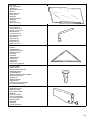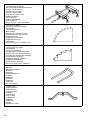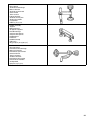
1
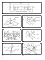
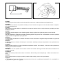
GB Compound Miter Saw Instruction Manual F Scie à coupe d’onglet mixte Manuel d’instructions D Gehrungs- und Kappsäge Betriebsanleitung I Sega a quartabuono composta Istruzioni per l’uso NL Gecombineerde verstekzaag Gebruiksaanwijzing E Sierra de inglete mixta Manual de instrucciones P Serra de esquadria composta Manual de instruções DK Afkorter-geringssav Brugsanvisning S Kap- och gerings kombinationssåg Bruksanvisning N Kompound gjæringssag Bruksanvisning SF Yhdistetty jiirisaha Käyttöohje GR Σύνθετος πριονωτς δίσκος Οδηγίες χρήσεως LS1040 1 2 1 3 2 3 1 5 2 4 3 4 6 9 7 8 7 5 6 11 12 15 13 14 10 2 8 17 18 16 7 13 9 19 20 9 10 22 21 23 11 12 24 26 25 13 14 29 27 28 15 16 3 30 7 29 17 18 31 34 32 33 135 mm 19 20 19 35 9 36 35 37 21 22 38 41 42 39 27 43 40 23 4 24 27 45 44 9 25 26 47 48 50 46 48 49 27 28 51 52 29 30 53 40 54 55 56 31 5 57 58 90 mm 25 mm 90 mm 107 mm 107 mm 90 mm 59 59 32 62 60 40 34 61 46 33 34 64 (4) (3) (2) (1) 35 65 63 35 36 68 13 62 35 66 37 67 36 37 6 38 69 39 70 71 40 Symbols The following show the symbols used for the tool. Be sure that you understand their meaning before use. Symboles Nous donnons ci-dessous les symboles utilisés pour l’outil. Assurez-vous que vous en avez bien compris la signification avant d’utiliser l’outil. Symbole Die folgenden Symbole werden für die Maschine verwendet. Machen Sie sich vor der Benutzung unbedingt mit ihrer Bedeutung vertraut. Symboli Per questo utensile vengono usati i simboli seguenti. Bisogna capire il loro significato prima di usare l’utensile. Symbolen Voor dit gereedschap worden de volgende symbolen gebruikt. Zorg ervoor dat u de betekenis van deze symbolen begrijpt alvorens het gereedschap te gebruiken. Símbolos A continuación se muestran los símbolos utilizados con esta herramienta. Asegúrese de que entiende su significado antes de usarla. Símbolos O seguinte mostra os símbolos utilizados para a ferramenta. Certifique-se de que compreende o seu significado antes da utilização. Symboler Nedenstående symboler er anvendt i forbindelse med denne maskine. Vær sikker på, at De har forstået symbolernes betydning, før maskinen anvendes. Symboler Det följande visar de symboler som används för den här maskinen. Se noga till att du förstår deras innebörd innan maskinen används. Symbolene Følgende viser de symblene som brukes for maskinen. Det er viktig å forstå betydningen av disse før maskinen tas i bruk. Symbolit Alla on esitetty koneessa käytetyt symbolit. Opettele näiden merkitys, ennen kuin käytät konetta. Σύµβολα Τα ακλουθα δείχνουν τα σύµβολα που χρησιµοποιούνται για το µηχάνηµα. Βεβαιωθείτε τι καταλαβαίνετε τη σηµασία τους πριν απ τη χρήση. 7 ❏ ❏ ❏ ❏ ❏ ❏ Read instruction manual. Lire le mode d’emploi. Bitte Bedienungsanleitung lesen. Leggete il manuale di istruzioni. Lees de gebruiksaanwijzing. Lea el manual de instrucciones. ❏ ❏ ❏ ❏ ❏ ❏ Leia o manual de instruções. Læs brugsanvisningen. Läs bruksanvisningen. Les bruksanvisingen. Katso käyttöohjeita. ∆ιαβάστε τις οδηγίες χρήσης. ❏ ❏ ❏ ❏ ❏ ❏ DOUBLE INSULATION DOUBLE ISOLATION DOPPELT SCHUTZISOLIERT DOPPIO ISOLAMENTO DUBBELE ISOLATIE DOBLE AISLAMIENTO ❏ ❏ ❏ ❏ ❏ ❏ DUPLO ISOLAMENTO DOBBELT ISOLERET DUBBEL ISOLERING DOBBEL ISOLERING KAKSINKERTAINEN ERISTYS ∆ΙΠΛΗ ΜΟΝΩΣΗ ❏ ❏ ❏ ❏ ❏ ❏ ❏ ❏ ❏ ❏ ❏ ❏ Do not place hand or fingers close to the blade. Ne pas placer les mains ou les doigts près de la lame. Halten Sie Hände oder Finger vom Sägeblatt fern. Non avvicinare le mani o le dita alla lama. Kom met uw handen of vingers niet te dicht bij het zaagblad. No ponga la mano ni los dedos cerca del disco. Não coloque a sua mão ou dedos perto da lâmina. Hold hænder og fingre på god afstand af klingen. Håll inte händer eller fingrar i närheten av klingan. Ikke plasser hånd eller fingre i nærheten av bladet. Älä sijoita käsiä äläkä sormia terän lähelle. Μη βάζετε το χέρι ή τα δάκτυλα κοντά στην λάµα. ❏ To avoid injury from flying debris, keep holding the saw head down, after making cuts, until the blade has come to a complete stop. ❏ Pour éviter les blessures causées par les objets projetés, maintenez la tête de la scie en position basse une fois la coupe terminée, jusqu’à ce que la lame soit complètement arrêtée. ❏ Um Verletzungen durch herausgeschleuderte Teile zu vermeiden, halten Sie den Sägekopf nach Ausführung von Schnitten abgesenkt, bis das Sägeblatt völlig zum Stillstand gekommen ist. ❏ Per evitare lesioni dalle schegge volanti, dopo aver eseguito il taglio tenere abbassata la testa sega finché la lama non si è arrestata completamente. ❏ Om verwonding door weggeslingerd zaagafval te voorkomen, dient u na het voltooien van een snede de zaagkop omlaag te houden totdat het zaagblad volledig tot stilstand is gekomen. ❏ Para evitar sufrir heridas a causa de restos que salen despedidos, siga sujetando la cabeza de la sierra hacia abajo, al terminar los cortes, hasta que el disco se haya parado completamente. ❏ Para evitar danos causados por aparas que saltem, mantenha a cabeça da serra para baixo, depois de terminar os cortes, até que a lâmina esteja completamente parada. ❏ For at undgå at komme til skade på grund af flyvende affald, skal man holde savhovedet nede efter skæring, indtil savklingen står helt stille. ❏ För att inte skadas av kringflygande flis efter genomförd sågning ska såghuvudet hållas nere tills klingan har stannat helt. ❏ For å unngå skader som følge av flygende flis, må du holde saghodet nede etter at sagingen er avsluttet, helt til bladet har stoppet helt. ❏ Pidä sahan pää sahauksen jälkeen alhaalla, kunnes saha on kokonaan pysähtynyt välttääksesi lentävien roskien aiheuttaman loukkaantumisen. ❏ Για να αποφύγετε τραυµατισµ απ ιπτάµενα τεµαχίδια, κρατάτε το πρινι µε το κεφάλι προς τα κάτω, αφού κάνετε κοπές, µέχρι η λάµα να σταµατήσει τελείως. 8 ❏ For your safety, remove chips, small pieces, etc. from the table top before operation. ❏ Pour votre sécurité, retirez les copeaux et autres petites pièces présentes sur la table avant de commencer le travail. ❏ Zur Sicherheit sollte die Tischplatte vor dem Betrieb von Spänen, Kleinteilen usw. gesäubert werden. ❏ Per la propria sicurezza, togliere i trucioli, frammenti, ecc., dalla superficie superiore del piano di taglio prima di procedere. ❏ Verwijder voor uw eigen veiligheid zaagafval, stukjes hout e.d. van de werktafel alvorens te gaan zagen. ❏ Por su propia seguridad, retire las virutas, trozos pequeños, etc., de encima de la mesa de trabajo antes de iniciar la tarea. ❏ Para sua segurança, retire aparas, peças pequenas, etc., de cima da bancada antes da operação. ❏ Af sikkerhedsårsager skal spåner, små stykker etc. fjernes fra bordtoppen inden anvendelsen. ❏ Av säkerhetsskäl bör flisor och småbitar avlägsnas från bordet före användningen. ❏ For din egen sikkerhets skyld må du fjerne trebiter, flis osv. fra sagbordet før du begynner å bruke maskinen. ❏ Poista turvallisuuden vuoksi lastut, pienet palaset yms. pöydältä ennen työskentelyä. ❏ Για την ασφάλειά σας, αφαιρέστε τα αποκοπίδια, µικρά κοµµάτια, κλπ. απ το τραπέζι πριν απ την λειτουργία. ❏ Always set SUB-FENCE to left position when performing left bevel cuts. Failure to do so may cause serious injury to operator. ❏ Lorsque vous effectuez des coupes en biseau sur la gauche, placez toujours la BUTÉE PAREÉCLATS ROTATIVE à gauche. Sinon, il y a risque de blessure grave. ❏ Stellen Sie den ZUSATZANSCHLAG bei der Durchführung von Neigungsschnitten immer auf die linke Position. Anderenfalls kann die Bedienungsperson ernsthaft verletzt werden. ❏ Posizionare sempre la guida pezzo secondaria a sinistra prima di eseguire i tagli a unghia. In caso contrario, c’è pericolo di lesioni serie all’operatore. ❏ Zet de HULPGELEIDER altijd in de linkse positie wanneer u linkse schuine sneden wilt zagen. Als u dit niet doet, kan de gebruiker ernstige verwonding oplopen. ❏ Ponga siempre la GUÍA AUXILIAR en la posición izquierda cuando realice cortes en bisel izquierdo. De lo contrario, podrá sufrir graves heridas. ❏ Coloque sempre a GUIA AUXILIAR no lado esquerdo quando executa cortes de bisel à esquerda. Se não o fizer pode ferir o operador. ❏ Anbing altid hjælpeanslaget (SUB-FENCE) i venstre position, når der laves skråsnit. Forsømmelse af dette kan bevirke, at operatøren kommer alvorligt til skade. ❏ Sätt alltid stödanhållet i vänsterläge vid vinkelsågning åt vänster. I annat fall kan användaren skadas allvarligt. ❏ Ved gjæringssaging i vertikalplanet må du alltid sette HJELPEVERNET i venstre posisjon. Hvis dette ikke gjøres, kan operatøren få alvorlige skader. ❏ Aseta ALIOHJAIN aina vasemmalle tehdessäsi vasemmanpuoleisia viistesahauksia. Jos tätä ei tehdä, käyttäjä voi loukkaantua vakavasti. ❏ Πάντοτε ρυθµίζετε το SUB-FENCE (ΥΠΟ-ΦΡΑΚΤΗ) στην αριστερή θέση ταν εκτελείτε αριστερές λοξές κοπές. Αµέλεια να το κάνετε µπορεί να προκαλέσει σοβαρ τραυµατισµ στον χρήστη. 9 ENGLISH Explanation of general view 1 2 3 4 5 6 7 8 9 10 11 12 13 14 15 16 17 18 19 20 21 22 23 24 Base Hex bolt Auxiliary plate Nut Bolt Center cover Socket wrench Shaft lock Loosen Arrow Blade case Arrow Saw blade Spindle Flange Ring Flange Hex bolt Tighten Safety cover Dust spout Dust bag Fastener Lock-off button 25 26 27 28 29 30 31 32 33 34 35 36 37 38 39 40 41 42 43 44 45 46 47 48 Switch trigger Lever Turn base Kerf board Sub-fence Adjusting bolt Pointer Miter scale Latch spring Grip Lever Bevel scale Pointer Vise rod Screws Guide fence Vise arm Clamp screw Support Knob Projection Holder Screw Holder assembly 49 50 51 52 53 54 55 56 57 58 59 60 61 62 63 64 65 66 67 68 69 70 71 Screw Rod 12 Cutting line Groove Vise Spacer block Aluminum extrusion Spacer block Over 10 mm Over 460 mm Hole Set plate Screw Triangular rule Hex bolts Arm Hex bolt (A) Top surface of turn base Arm holder Hex bolt (B) Limit mark Screwdriver Brush holder cap SPECIFICATIONS Model LS1040 Blade diameter .................................................................................................................................. 255 mm — 260 mm Hole (arbor) diameter For all countries other than European countries .......................................................................... 25.4 mm and 25 mm For European countries ...................................................................................................................................... 30 mm Max. cutting capacities (H x W) with blade 260 mm in diameter Miter angle 0° 45° (left and right) 0° 93 mm x 95 mm 69 mm x 135 mm 93 mm x 67 mm 69 mm x 95 mm 45° (left) 53 mm x 95 mm 35 mm x 135 mm 49 mm x 67 mm 35 mm x 94 mm Bevel angle No load speed (min–1) ............................................................................................................................................ 4,600 Dimensions (L x W x H) ..................................................................................................... 530 mm x 476 mm x 532 mm Net weight ...............................................................................................................................................................11 kg • Due to our continuing program of research and development, the specifications herein are subject to change without notice. • Note: Specifications may differ from country to country. Intended use The tool is intended for accurate straight and miter cutting in wood. With appropriate saw blades, aluminum can also be sawed. Power supply The tool should be connected only to a power supply of the same voltage as indicated on the nameplate, and can only be operated on single-phase AC supply. They are double-insulated in accordance with European Standard and can, therefore, also be used from sockets without earth wire. 10 For public low-voltage distribution systems of between 220 V and 250 V Switching operations of electric apparatus cause voltage fluctuations. The operation of this device under unfavorable mains conditions can have adverse effects to the operation of other equipment. With a mains impedance equal or less than 0.30 Ohms it can be presumed that there will be no negative effects. The mains socket used for this device must be protected with a fuse or protective circuit breaker having slow tripping characteristics. Safety hints For your own safety, please refer to enclosed safety instructions. ADDITIONAL SAFETY RULES 1. 2. 3. 4. 5. 6. 7. 8. 9. 10. 11. 12. 13. 14. 15. 16. 17. 18. 19. 20. 21. 22. 23. 24. 25. 26. 27. Wear eye protection. Do not operate saw without guards in place. Don’t use the tool in the presence of flammable liquids or gases. Check the blade carefully for cracks or damage before operation. Replace cracked or damaged blade immediately. Use only flanges specified for this tool. Be careful not to damage the arbor, flanges (especially the installing surface) or bolt. Damage to these parts could result in blade breakage. Make sure that the turn base is properly secured so it will not move during operation. For your safety, remove the chips, small pieces, etc. from the table top before operation. Avoid cutting nails. Inspect for and remove all nails from the workpiece before operation. Make sure the shaft lock is released before the switch is turned on. Be sure that the blade does not contact the turn base in the lowest position. Hold the handle firmly. Be aware that the saw moves up or down slightly during start-up and stopping. Do not perform any operation freehand. The workpiece must be secured firmly against the turn base and guide fence with the vise during all operations. Never use your hand to secure the workpiece. Keep hands out of path of saw blade. Avoid contact with any coasting blade. It can still cause severe injury. Never reach around saw blade. Make sure the blade is not contacting the workpiece before the switch is turned on. Before using the tool on an actual workpiece, let it run for a while. Watch for vibration or wobbling that could indicate poor installation or a poorly balanced blade. Wait until the blade attains full speed before cutting. Stop operation immediately if you notice anything abnormal. Do not attempt to lock the trigger in the ON position. Shut off power and wait for saw blade to stop before servicing or adjusting tool. Be alert at all times, especially during repetitive, monotonous operations. Don’t be lulled into a false sense of security. Blades are extremely unforgiving. Always use accessories recommended in this manual. Use of improper accessories such as abrasive wheels may cause an injury. Don’t abuse cord. Never yank cord to disconnect it from the receptacle. Keep cord away from heat, oil, water and sharp edges. Do not use the saw to cut other than aluminum, wood or similar materials. Connect compound miter saws to a dust collecting device when sawing. Select saw blades in relation to the material to be cut. 28. Take care when slotting. 29. Replace the kerf board when worn. SAVE THESE INSTRUCTIONS. OPERATING INSTRUCTIONS Carrying tool (Fig. 1) When carrying the tool, lower the handle fully and press the stopper pin to lock the handle in the lowered position. Secure the turn base by means of the grip. The tool can then be conveniently carried by the carrying grip. WARNING: • Be sure that the tool is unplugged first. • Stopper pin is for carrying purposes only and not for any cutting operations. Installing auxiliary plate (Fig. 2 & 3) Install the auxiliary plate using the notch in the tool’s base and secure it by tightening the hex bolt. Bench mounting saw (Fig. 4) This tool should be bolted with two bolts to a level and stable surface using the bolt holes provided in the tool’s base. This will help prevent tipping and possible injury. Installing or removing saw blade Important: Always be sure that the tool is switched off and unplugged before installing or removing the blade. To remove the blade, use the socket wrench to loosen the hex bolt holding the center cover by turning it more than three turns counterclockwise. Raise the safety cover and center cover. (Fig. 5) Press the shaft lock so that the blade cannot revolve and use the socket wrench to loosen the hex bolt clockwise. Then remove the hex bolt, outer flange and blade. (Fig. 6) To install the blade, mount it onto the spindle, making sure that the direction of the arrow on the surface of the blade matches the direction of the arrow on the blade case. (Fig. 7) CAUTION: • For all countries other than European countries (Fig. 8) The silver ring 25.4 mm in outer diameter is factoryinstalled onto the spindle. The black ring 25 mm in outer diameter is included as standard equipment. Before mounting the blade onto the spindle, always be sure that the correct ring for the arbor hole of the blade you intend to use is installed onto the spindle. • For European countries (Fig. 8) The ring 30 mm in outer diameter is factory-installed onto the spindle. Install the flange and hex bolt, and then use the socket wrench to tighten the hex bolt securely counterclockwise while pressing the shaft lock. Then tighten the hex bolt clockwise to secure the center cover. (Fig. 9) CAUTION: Use only the Makita socket wrench provided to install or remove the blade. Failure to do so may result in overtightening or insufficient tightening of the hex bolt. This could cause an injury. 11 Safety cover (Fig. 10) When lowering the handle, the safety cover rises automatically. The cover returns to its original position when the cut is completed and the handle is raised. NEVER DEFEAT OR REMOVE THE SAFETY COVER. In the interest of your personal safety, always maintain the safety cover in good condition. Any irregular operation of the safety cover should be corrected immediately. NEVER USE THE TOOL WITH A FAULTY SAFETY COVER. If the see-through safety cover becomes dirty, or sawdust adheres to it in such a way that the blade and/ or workpiece is no longer easily visible, unplug the saw and clean the cover carefully with a damp cloth. Do not use solvents or any petroleum-based cleaners on the plastic cover. Dust bag (Fig. 11 & 12) The use of the dust bag makes cutting operations clean and dust collection easy. To attach the dust bag, fit the bag’s entry port over the dust spout. When the dust bag is about half full, remove the dust bag from the tool and pull the fastener out. Empty the dust bag of its contents, tapping it lightly so as to remove particles adhering to the insides which might hamper further collection. Switch action CAUTION: • Before plugging in the tool, always check to see that the switch trigger actuates properly and returns to the “OFF” position when released. • When not using the tool, remove the lock-off button and store it in a secure place. This prevents unauthorized operation. • Do not pull the trigger hard without pressing in the lockoff button. This can cause breakage of the switch. For all countries other than European countries (Fig. 13) To prevent the trigger from being accidentally pulled, a lock-off button is provided. To start the tool, press in the lock-off button and pull the trigger. Release the trigger to stop. For European countries (Fig. 14) To prevent the trigger from being accidentally pulled, a lock-off button is provided. To start the tool, push the lever to the left, press in the lock-off button and then pull the trigger. Release the trigger to stop. Kerf board (Fig. 15) This tool is provided with the kerf board in the turn base. If the kerf groove has not yet been cut in the kerf board by the factory, you should cut the groove before actually using the tool to cut a workpiece. Switch on the tool and lower the blade gently to cut a groove in the kerf board. Sub-fence (Fig. 16 & 17) This tool is equipped with the sub-fence which should ordinarily be positioned as shown in Fig. 16. However, when performing left bevel cuts, set it to the left position as shown in Fig. 17. Maintaining maximum cutting capacity (Fig. 18 & 19) Unplug the tool before any adjustment is attempted. This tool is factory adjusted to provide the max. cutting capacity for a 260 mm saw blade. When the diameter of the blade has been reduced due to sharpening, adjust the depth adjusting bolt by turning it with the socket wrench. The saw blade is lowered by turning the depth adjusting bolt counterclockwise and raised by turning it clockwise. Adjust so that when the handle is in the fully lowered position, there will be a distance of about 135 mm from the front face of the guide fence to the point where the front edge of the blade enters the kerf. With the tool unplugged, rotate the blade by hand while holding the handle all the way down. Be sure that the blade does not contact any part of the lower base when the handle is lowered completely. Positioning for adjusting the miter angle (Fig. 20) Loosen the grip by turning counterclockwise. Turn the turn base while pressing down the latch spring. When you have moved the grip to the position where the pointer indicates the desired angle on the miter scale, securely tighten the grip clockwise. CAUTION: When turning the turn base, be sure to raise the handle fully. Positioning for adjusting the bevel angle (Fig. 21 & 22) The saw blade tilts up to 45° to the left only when the sub-fence is set to the left position as shown in Fig. 17. To adjust the bevel angle, loosen the lever at the rear of the tool. Tilt the blade to the left so that the pointer indicates the desired angle on the bevel scale. Then tighten the lever firmly to secure the arm. CAUTION: When tilting the saw blade, be sure to raise the handle fully. Securing workpiece WARNING: It is extremely important to always secure the workpiece properly and tightly with the vise. Failure to do so can cause the tool to be damaged and/or the workpiece to be destroyed. PERSONAL INJURY MAY ALSO RESULT. Also, after a cutting operation, DO NOT raise the blade until the blade has come to a complete stop. 1. Vertical vise (Fig. 23 & 27) The vertical vise can be installed on the guide fence or the holder assembly (optional accessory). Insert the vise rod into the hole in the guide fence or the holder assembly and tighten the screw to secure the vise rod. Position the vise arm according to the thickness and shape of the workpiece and secure the vise arm by tightening the screw. Press the workpiece flat against the guide fence and the turn base. Position the workpiece at the desired cutting position and secure it firmly by tightening the clamp screw. CAUTION: The workpiece must be secured firmly against the turn base and guide fence with the vise during all operations. 12 If some part contacts the vise, re-position the vise arm. Press the workpiece flat against the guide fence and the turn base. Position the workpiece at the desired cutting position and secure it firmly by tightening the clamp screw of the vise. 2. 3. CAUTION: When cutting long workpieces, use supports that are as high as the top surface level of the turn base. (Fig. 24) Horizontal vise (optional accessory) (Fig. 25 & 26) The horizontal vise can be installed on either the left or right side of the base. When performing 15° or greater miter cuts, install the horizontal vise on the side opposite the direction in which the turn table is to be turned. By turning the knob on the vise counterclockwise, the screw is released and the vise shaft can be moved rapidly in and out. By turning the knob clockwise, the screw remains secured. To grip workpieces, turn the knob gently clockwise until the projection reaches its topmost position, then fasten securely. If the knob is forced in or pulled out while being turned clockwise, the projection may stop at an angle. In this case, turn the knob back counterclockwise until the screw is released, before turning again gently clockwise. Holders and holder assembly (optional accessories) The holders and the holder assembly can be installed on either side as a convenient means of supporting workpieces horizontally. Install them as shown in Fig. 27. Then tighten the screws firmly to secure the holders and the holder assembly. (Fig. 27) When cutting long workpieces, use the holder-rod assembly (optional accessory). It consists of two holder assemblies and two rods 12. (Fig. 28) When cutting with this tool, the thickness of the blade is cut out of the workpiece as well. Therefore, your cutting line should be on either the left or right side of the groove in the kerf board. Switch on the tool and wait until the blade attains full speed before lowering gently into the cut. When the blade contacts the workpiece, gradually bear down on the handle to perform the cut. When the cut is completed, switch off the tool and WAIT UNTIL THE BLADE HAS COME TO A COMPLETE STOP before returning the blade to its fully elevated position. A thin piece of cut off material could otherwise contact the coasting blade and be thrown around dangerously. (Fig. 29) 1. Miter cutting Refer to the previously covered “Positioning for adjusting the miter angle”. 2. Bevel cut (Fig. 30) • Left 0° – 45° bevel cuts can be performed. • Set the sub-fence to the left position as shown in Fig. 17. Loosen the lever and tilt the saw blade to set the bevel angle. Be sure to retighten the lever firmly to secure the selected bevel angle safely. Secure the workpiece with the vise. Switch on the tool and wait until the blade attains full speed. Then gently lower the handle to the fully lowered position while applying pressure in parallel with the blade. When the cut is completed, switch off the tool and WAIT UNTIL THE BLADE HAS COME TO A COMPLETE STOP before returning the blade to its fully elevated position. CAUTION: Always support long workpieces level with the top surface of the turn base for accurate cuts and to prevent dangerous loss of control of the tool. Operation CAUTION: • Before use, be sure to release the handle from the lowered position by pulling the stopper pin. • Make sure the blade is not contacting the workpiece, etc. before the switch is turned on. • Do not apply excessive pressure on the handle when cutting. Too much force may result in overload of the motor and/or decreased cutting efficiency. • Gently press down the handle to perform the cut. If the handle is pressed down with force or if lateral force is applied, the blade will vibrate and leave a mark (saw mark) in the workpiece and the precision of the cut will be impaired. 3. CAUTION: • When performing the bevel cut with the workpiece secured on the left side of the turn base, it will create a condition where the piece cut off will come to rest on the blade. If the blade is raised while the blade is still rotating, this piece may be caught in the blade, causing fragments to be scattered around which is dangerous. The blade should be gently raised only after the blade has come to a complete stop. • When pressing down the handle, apply pressure in parallel with the blade. If a force is applied perpendicularly to the turn base or if the pressure direction is changed during a cut, the precision of the cut will be impaired. • Always set the sub-fence to the left position as shown in Fig. 17 when performing bevel cuts. Compound cutting Compound cutting can be performed at angle shown in the table below. Bevel angle Miter angle 45° Left and right 0° – 45° When performing the compound cutting, refer to “Miter cutting” and “Bevel cut” explanations. 13 4. 5. 6. Cutting aluminum extrusion (Fig. 31) When securing aluminum extrusions, use spacer blocks or pieces of scrap as shown in Fig. 31 to prevent deformation of the aluminum. Use a cutting lubricant when cutting the aluminum extrusion to prevent build-up of the aluminum material on the blade. CAUTION: Never attempt to cut thick or round aluminum extrusions. Thick aluminum extrusions may come loose during operation and round aluminum extrusions cannot be secured firmly with this tool. Wood facing (Fig. 32) Use of wood facing helps to assure splinter-free cuts in workpieces. Attach a wood facing to the guide fence using the holes in the guide fence. CAUTION: • Use straight wood of even thickness as the wood facing. • See Fig. 32 concerning the dimensions for a suggested wood facing. Cutting repetitive lengths (Fig. 33) When cutting several pieces of stock to the same length, ranging from 240 mm to 400 mm, use of the set plate (optional accessory) will facilitate more efficient operation. Install the set plate on the holder as shown in Fig. 33. Align the cutting line on your workpiece with either the left or right side of the groove in the kerf board, and while holding the workpiece from moving, move the set plate flush against the end of the workpiece. Then secure the set plate with the screw. When the set plate is not used, loosen the screw and turn the set plate out of the way. MAINTENANCE CAUTION: Always be sure that the tool is switched off and unplugged before carrying out any work on the tool. Adjusting the cutting angle This tool is carefully adjusted and aligned at the factory, but rough handling may have affected the alignment. If your tool is not aligned properly, perform the following: 1) Miter angle (Fig. 34 & 35) Loosen the grip and set the turn base at zero degrees by turning the turn base. Tighten the grip securely and loosen the hex bolts on the guide fence. Square the side of the blade with the face of the guide fence using a triangular rule, try-square, etc. by moving the right side of the guide fence. Then securely tighten the hex bolts on the guide fence in the order indicated in Fig. 35. 2) Bevel angle i) 0° bevel angle Loosen the lever at the rear of the tool. Loosen the hex nut and turn the hex bolt (A) two or three revolutions clockwise so that the blade tilts to the right. (Fig. 36) Lower the handle fully and square the side of the blade with the top surface of the turn base using the triangular rule, try-square, etc. by turning the hex bolt (A) counterclockwise. Then tighten the hex nut to secure the hex bolt (A). (Fig. 37) Make sure that the pointer on the arm indicates 0° on the bevel scale on the arm holder. If the pointer does not indicate 0°, loosen the screw securing the pointer and adjust the pointer. (Fig. 38) ii) 45° bevel angle Adjust 45° bevel angle only after performing 0° bevel angle adjustment. To adjust 45° bevel angle, loosen the lever and tilt the saw blade to the left fully. Make sure that the pointer on the arm indicates 45° on the bevel scale on the arm holder. If the pointer does not indicate 45°, turn the hex bolt (B) on the side of the arm until the pointer indicates 45°. (Fig. 38) Replacement of carbon brushes (Fig. 39 & 40) Replace carbon brushes when they are worn down to the limit mark. Both identical carbon brushes should be replaced at the same time. To maintain product safety and reliability, repairs, maintenance or adjustment should be carried out by a Makita Authorized Service Center. 14 NEDERLANDS Verklaring van algemene gegevens 1 2 3 4 5 6 7 8 9 10 11 12 13 14 15 16 17 18 19 20 21 22 23 24 Voetstuk Zeskante bout Hulpplaat Moer Bout Middenkap Dopsleutel Asvergrendeling Losmaken Pijl Zaagbladkast Pijl Zaagblad As Flens Ring Flens Zeskante bout Vastmaken Veiligheidskap Stofuitlaat Stofzak Sluiting Ontgrendelknop 25 26 27 28 29 30 31 32 33 34 35 36 37 38 39 40 41 42 43 44 45 46 47 48 Trekkerschakelaar Hendel Draaibaar voetstuk Zaagsnede-plaat Hulpgeleider Stelbout Wijzer Verstekschaal Slotveer Handgreep Hendel Schuine-hoek schaal Wijzer Spanschroefstang Schroeven Geleider Spanschroefarm Klembout Steun Knop Uitsteeksel Houder Schroef Houdermontage 49 50 51 52 53 54 55 56 57 58 59 60 61 62 63 64 65 66 67 68 69 70 71 Schroef Stang 12 Zaaglijn Groef Spanschroef Vulblok Aluminium werkstuk Vulblok Meer dan 10 mm Meer dan 460 mm Gat Stelplaat Schroef Driehoeksliniaal Zeskante bouten Arm Zeskante bout (A) Bovenvlak van draaibaar voetstuk Armhouder Zeskante bout (B) Limietmerkstreep Schroevedraaier Borstelhouderdop TECHNISCHE GEGEVENS Model LS1040 Diameter van zaagblad .....................................................................................................................255 mm — 260 mm Diameter van gat (asgat) Voor alle niet-Europese landen ...................................................................................................... 25,4 mm en 25 mm Voor alle Europese landen ................................................................................................................................. 30 mm Max. zaagkapaciteiten (H x B) met een zaagblad van 260 mm in diameter Verstekhoek 0° 45° (links en rechts) 0° 93 mm x 95 mm 69 mm x 135 mm 93 mm x 67 mm 69 mm x 95 mm 45° (links) 53 mm x 95 mm 35 mm x 135 mm 49 mm x 67 mm 35 mm x 94 mm Schuine hoek Toerental onbelast (min–1) ...................................................................................................................................... 4 600 Afmetingen (L x B x H) ......................................................................................................530 mm x 476 mm x 532 mm Netto gewicht .......................................................................................................................................................... 11 kg • In verband met ononderbroken research en ontwikkeling behouden wij ons het recht voor bovenstaande technische gegevens te wijzigen zonder voorafgaande kennisgeving. • Opmerking: De technische gegevens kunnen van land tot land verschillen. Doeleinden van gebruik Dit gereedschap is bedoeld voor nauwkeurig recht zagen en verstekzagen in hout. Bij gebruik van de geschikte zaagbladen kan ook aluminium worden gezaagd. Stroomvoorziening Het gereedschap mag alleen worden aangesloten op een stroombron van hetzelfde voltage als aangegeven op de naamplaat, en kan alleen op enkel-fase wisselstroom worden gebruikt. Het gereedschap is dubbel-geïsoleerd volgens de Europese standaard en kan derhalve ook op een niet-geaard stopcontact worden aangesloten. 33 Voor openbare laagspanningsverdeelsystemen van tussen 220 V en 250 V Schakelbedieningen van elektrische toestellen veroorzaken spanningsschommelingen. De bediening van dit gereedschap onder ongunstige lichtnetomstandigheden kan een nadelige invloed hebben op de bediening van andere apparatuur. Het kan worden aangenomen dat er geen negatieve effecten zullen zijn wanneer de netimpedantie gelijk is aan of minder is dan 0,30 Ohm. Het stopcontact dat voor dit gereedschap wordt gebruikt, moet beveiligd zijn door een zekering of een stroomonderbreker met trage afschakelkarakteristieken. Veiligheidswenken Voor uw veiligheid dient u de bijgevoegde Veiligheidsvoorschriften nauwkeurig op te volgen. AANVULLENDE VEILIGHEIDSVOORSCHRIFTEN 1. 2. 3. 4. 5. 6. 7. 8. 9. 10. 11. 12. 13. 14. 15. 16. 34 Draag oogbescherming. Gebruik de zaag niet zonder dat de beschermkappen zijn aangebracht. Gebruik de machine niet in de nabijheid van ontvlambare vloeistoffen of gassen. Controleer het zaagblad zorgvuldig op barsten of beschadiging, alvorens de machine te gaan gebruiken. Een gebarsten of beschadigd zaagblad dient onmiddellijk te worden vervangen. Gebruik alleen flenzen die voor deze machine gemaakt zijn. Zorg ervoor dat de as, de flenzen (vooral het montagevlak) of de bout niet worden beschadigd. Beschadiging van deze onderdelen kan zaagbladbreuk veroorzaken. Controleer of het draaibaar voetstuk goed vastzit, zodat het tijdens het zagen niet kan bewegen. Verwijder voor uw eigen veiligheid zaagafval, kleine stukjes hout e.d. van de werktafel alvorens te gaan zagen. Zaag niet op spijkers. Inspecteer het werkstuk en verwijder alle eventuele spijkers alvorens met het zagen te beginnen. Zet de asvergrendeling in de vrije stand alvorens de trekkerschakelaar in te drukken. Zorg ervoor dat het zaagblad in zijn laagste positie niet in aanraking komt met het draaibaar voetstuk. Houd het handvat stevig vast. Denk eraan dat de zaag bij het starten en stoppen een beetje op- en neergaat. Zaag nooit met het werkstuk in uw hand. Zet het werkstuk altijd stevig vast op het draaibaar voetstuk en tegen de geleider met behulp van de spanschroef. Gebruik nooit uw hand om het werkstuk vast te houden. Houd altijd uw handen uit de buurt van het zaagblad. Raak het freewheelende zaagblad niet aan, aangezien dit nog ernstige verwondingen kan veroorzaken. Probeer tijdens het zagen nooit iets vast te pakken in de omgeving van het zaagblad. Controleer vóór het inschakelen of het zaagblad niet in contact is met het werkstuk. 17. Laat de machine een tijdje draaien alvorens deze op het werkstuk te gebruiken. Controleer op trillingen of schommelingen die op onjuiste installatie of op een slecht gebalanceerd zaagblad kunnen wijzen. 18. Wacht totdat het zaagblad op volle toeren draait, alvorens het werkstuk te zagen. 19. Stop onmiddellijk met zagen indien u iets abnormaals opmerkt. 20. Probeer niet de trekkerschakelaar in de AAN positie te vergrendelen. 21. Schakel de spanning uit en wacht totdat het zaagblad volledig tot stilstand is gekomen, alvorens de machine een onderhoudsbeurt te geven of af te stellen. 22. Laat uw aandacht nooit verslappen, vooral niet wanneer het werk saai is en uit herhalingen bestaat. Laat u niet door een vals gevoel van veiligheid misleiden, aangezien zaagbladen altijd gevaar kunnen opleveren. 23. Gebruik uitsluitend de accessoires die in deze gebruiksaanwijzing worden aanbevolen. Het gebruik van ongeschikte accessoires, zoals slijpschijven, kan verwonding veroorzaken. 24. Houd het snoer in goede conditie. Trek aan de stekker en niet aan het snoer zelf om dit uit het stopcontact te verwijderen. Houd het snoer uit de buurt van hitte, olie, water en scherpe randen. 25. Gebruik de zaag niet voor het zagen van andere materialen dan aluminium, hout of gelijksoortige materialen. 26. Sluit gecombineerde verstekzagen tijdens het zagen aan op een stofvanginrichting. 27. Kies de zaagbladen in overeenstemming met het te zagen materiaal. 28. Wees voorzichtig wanneer u gleuven zaagt. 29. Vervang de zaagsnede-plaat wanneer deze versleten is. BEWAAR DEZE VOORSCHRIFTEN. BEDIENINGSVOORSCHRIFTEN Dragen van de machine (Fig. 1) Om de machine te dragen, brengt u het handvat helemaal omlaag en drukt u de aanslagpen naar binnen om het handvat in de omlaagpositie vast te zetten. Zet het draaibaar voetstuk vast door middel van de handgreep. De machine kan dan gemakkelijk bij de handgreep worden gedragen. WAARSCHUWING: • Trek eerst de stekker van de machine uit het stopcontact. • De aanslagpen is uitsluitend bedoeld voor het dragen van de machine en niet voor zaagbedieningen. Installeren van de hulpplaat (Fig. 2 en 3) Installeer de hulpplaat door gebruik te maken van de inkeping in het machinevoetstuk en zet deze vast door de zeskante bout aan te trekken. De zaag op een werktafel monteren (Fig. 4) Deze machine moet op een horizontaal en stabiel oppervlak worden gemonteerd door middel van twee bouten die u door de boutgaten in het machinevoetstuk steekt. Hierdoor wordt voorkomen dat de machine omkantelt en mogelijk verwondingen veroorzaakt. Installeren of verwijderen van het zaagblad Stofzak (Fig. 11 en 12) Belangrijk: Controleer altijd of de machine is uitgeschakeld en de stekker van het netsnoer uit het stopcontact is getrokken alvorens het zaagblad te installeren of te verwijderen. Door de stofzak te gebruiken wordt het zaagsel opgevangen en kunt u schoon werken. Voor het bevestigen van de stofzak monteert u de inlaat van de stofzak over de stofuitlaat op de machine. Wanneer de stofzak ongeveer halfvol is, verwijdert u deze van de machine en trekt u de sluiting eruit. Maak de stofzak leeg en tik er lichtjes op voor het verwijderen van achtergebleven stofdeeltjes waardoor de stofopvanging zou kunnen worden belemmerd. Om het zaagblad te verwijderen, gebruik de dopsleutel en draai de zeskante bout, waarmee de middenkap is vastgezet, meer dan drie slagen naar links om deze los te maken. Breng de veiligheidskap en de middenkap omhoog. (Fig. 5) Druk op de asvergrendeling zodat het blad niet kan ronddraaien en draai met de dopsleutel de zeskante bout naar rechts los. Verwijder vervolgens de zeskante bout, de buitenflens en het zaagblad. (Fig. 6) Om het zaagblad te installeren, monteert u het zaagblad op de as, ervoor zorgend dat de pijlen op het zaagblad en op de zaagbladkast in dezelfde richting wijzen. (Fig. 7) LET OP: • Voor alle niet-Europese landen (Fig. 8) De zilverring met een buitendiameter van 25,4 mm is in de fabriek op de as gemonteerd. De zwarte ring met een buitendiameter van 25 mm is als standaard uitrusting meegeleverd. Alvorens het blad op de as te monteren, moet u altijd ervoor zorgen dat de ring die geschikt is voor het asgat van het blad dat u gaat gebruiken, op de as is gemonteerd. • Voor Europese landen (Fig. 8) De ring met een buitendiameter van 30 mm is in de fabriek op de as gemonteerd. Monteer de flens en de zeskante bout, en draai dan met de dopsleutel de zeskante bout stevig naar links vast terwijl u de asvergrendeling ingedrukt houdt. Zet daarna de middenkap vast door de zeskante bout naar rechts vast te draaien. (Fig. 9) LET OP: Gebruik voor het installeren of verwijderen van het zaagblad uitsluitend de bijgeleverde Makita dopsleutel. Doet u dit niet, dan kan de zeskante bout te vast of te los worden aangedraaid, hetgeen verwondingen tot gevolg kan hebben. Veiligheidskap (Fig. 10) Wanneer het handvat omlaag wordt gebracht, gaat de veiligheidskap automatisch omhoog. De veiligheidskap keert naar haar oorspronkelijke positie terug wanneer het zagen beëindigd is en het handvat omhoog wordt gebracht. ZET DE VEILIGHEIDSKAP NOOIT VAST EN VERWIJDER DEZE NOOIT. Voor uw persoonlijke veiligheid dient de veiligheidskap altijd in goede staat te worden gehouden. Elke onregelmatigheid in de werking van de veiligheidskap dient onmiddellijk te worden hersteld. GEBRUIK DE MACHINE NOOIT MET EEN DEFECTE VEILIGHEIDSKAP. Wanneer de doorzichtige veiligheidskap vuil is of met zaagsel is bedekt zodat u het zaagblad en/of het werkstuk niet meer behoorlijk kunt zien, verwijder dan de stekker uit het stopcontact en reinig de veiligheidskap zorgvuldig met een bevochtigde doek. Gebruik geen oplosmiddelen of benzinehoudende schoonmaakmiddelen op de plastic kap. Werking van de schakelaar LET OP: • Alvorens de stekker in het stopcontact te steken, dient u altijd te controleren of de trekkerschakelaar goed werkt en bij loslaten naar de “OFF” stand terugkeert. • Verwijder de ontgrendelknop en bewaar deze op een veilige plaats wanneer u de machine niet gebruikt. Hierdoor voorkomt u ongeoorloofd gebruik van de machine. • Druk de trekkerschakelaar niet hard in zonder de ontgrendelknop in te drukken. Hierdoor kan de schakelaar namelijk breken. Voor alle niet-Europese landen (Fig. 13) Een ontgrendelknop is voorzien om te voorkomen dat de trekkerschakelaar per ongeluk wordt ingedrukt. Om de machine te starten, drukt u de ontgrendelknop in en daarna drukt u de trekkerschakelaar in. Om de machine te stoppen, laat u de trekkerschakelaar los. Voor Europese landen (Fig. 14) Een ontgrendelknop is voorzien om te voorkomen dat de trekkerschakelaar per ongeluk wordt ingedrukt. Om de machine te starten, duw de hendel naar links, druk de ontgrendelknop in en druk daarna de trekkerschakelaar in. Om de machine te stoppen, laat u de trekkerschakelaar los. Zaagsnede-plaat (Fig. 15) Deze machine is voorzien van een zaagsnede-plaat in het draaibaar voetstuk. Indien de zaagsnede-groef in de fabriek nog niet in de zaagsnede-plaat is gezaagd, dient u de groef erin te zagen alvorens de machine te gebruiken voor het zagen van een werkstuk. Schakel de machine in en breng het zaagblad langzaam omlaag om een groef in de zaagsnede-plaat te zagen. Hulpgeleider (Fig. 16 en 17) Deze machine is voorzien van een hulpgeleider die normaal in de positie afgebeeld in Fig. 16 moet staan. Wanneer u echter linkse schuine sneden wilt maken, moet u deze geleider in de linkerpositie afgebeeld in Fig. 17 zetten. 35 Handhaven van de maximale zaagcapaciteit (Fig. 18 en 19) 1. Trek de stekker van de machine uit het stopcontact alvorens afstellingen te maken. Deze machine is in de fabriek ingesteld voor het leveren van maximale zaagcapaciteit met een 260 mm zaagblad. Wanneer de diameter van het zaagblad vanwege herhaald aanscherpen is geslonken, dient u de diepte-afstelbout af te stellen door deze met de dopsleutel te draaien. Draai de diepte-afstelbout naar links om het zaagblad in een lagere positie te zetten, en naar rechts om het in een hogere positie te zetten. Stel zodanig af dat de afstand tussen het voorvlak van de geleider en het punt waar de voorrand van het zaagblad in de zaagsnede komt ongeveer 135 mm bedraagt wanneer het handvat zich in de laagste positie bevindt. Draai met de hand het zaagblad rond (met de stekker uit het stopcontact!) terwijl u het handvat volledig omlaag gedrukt houdt, en controleer of het zaagblad met geen enkel deel van het onderste voetstuk in aanraking komt wanneer het handvat helemaal omlaag is gebracht. LET OP: Tijdens alle bedieningen moet het werkstuk door de spanschroef stevig tegen het draaibaar voetstuk en de geleider worden gedrukt. Indien sommige delen met de spanschroef in aanraking komen, moet u de positie van de spanschroefarm opnieuw afstellen. Druk het werkstuk vlak tegen de geleider en het draaibaar voetstuk. Plaats het werkstuk in de gewenste zaagpositie en zet het stevig vast door de klembout van de spanschroef vast te draaien. Instellen van de verstekhoek (Fig. 20) Draai de handgreep naar links los. Verdraai het draaibaar voetstuk terwijl u de slotveer omlaag gedrukt houdt. Beweeg de handgreep naar de positie waarbij de wijzer de gewenste hoek op de verstekschaal aanwijst en draai dan de handgreep weer stevig naar rechts vast. LET OP: Voor het zagen van lange werkstukken dient u gebruik te maken van steunders die even hoog zijn als het bovenvlak van het draaibaar voetstuk. (Fig. 24) LET OP: Voor het verdraaien van het draaibaar voetstuk dient u het handvat in de hoogste positie te plaatsen. Instellen van de schuine hoek (Fig. 21 en 22) Het zaagblad kan 45° schuin omhoog naar links worden gezet alleen wanneer de hulpgeleider in de linker positie is gezet, zoals afgebeeld in Fig. 17. Om de schuine hoek in te stellen, maakt u de hendel aan de achterzijde van de machine los. Kantel het zaagblad naar links zodat de wijzer naar de gewenste hoek op de schuine-hoek schaal wijst. Draai daarna de hendel weer vast om de arm te vergrendelen. LET OP: Voor het schuin zetten van het zaagblad, dient u het handvat in de hoogste positie te plaatsen. Vastzetten van het werkstuk WAARSCHUWING: Het is uiterst belangrijk dat u het werkstuk altijd juist en stevig vastzet met behulp van de spanschroef. Wanneer u dit nalaat, kan de machine beschadiging oplopen en/of het werkstuk worden vernield. OOK KAN PERSOONLIJK LETSEL HET GEVOLG ZIJN. Nadat het zagen is beëindigd, dient u de zaag NIET op te tillen alvorens het zaagblad volledig tot stilstand is gekomen. 36 Verticale spanschroef (Fig. 23 en 27) De verticale spanschroef kan op de geleider of op de houdermontage (los verkrijgbaar accessoire) worden geïnstalleerd. Steek de stang van de spanschroef in het gat in de geleider of in de houdermontage en trek de schroef aan om de stang vast te zetten. Zet de arm van de spanschroef in de positie die geschikt is voor de dikte en vorm van het werkstuk en zet de arm vast door de schroef vast te draaien. Druk het werkstuk vlak tegen de geleider en het draaibare voetstuk. Plaats het werkstuk in de gewenste zaagpositie en zet het stevig vast door de klemschroef vast te draaien. 2. Horizontale spanschroef (los verkrijgbaar accessoire) (Fig. 25 en 26) De horizontale spanschroef kan aan de linker- of rechterzijde van het voetstuk worden geïnstalleerd. Voor het maken van versteksneden van 15° of meer, monteert u de horizontale spanschroef aan de tegenovergestelde zijde van de richting waarin het draaibare voetstuk zal worden gedraaid. Wanneer de knop op de spanschroef naar links wordt gedraaid, komt de schroef los en kunt u de as van de spanschroef snel naar binnen en naar buiten bewegen. Wanneer de knop naar rechts wordt gedraaid, blijft de schroef vast. Om het werkstuk te grijpen, draait u de knop langzaam naar rechts totdat het uitsteeksel in zijn hoogste positie komt te staan, en dan draait u de knop stevig vast. Indien de knop naar binnen of naar buiten wordt getrokken terwijl u deze naar rechts draait, kan het uitsteeksel in een schuine positie stoppen. In dit geval draait u de knop terug naar links totdat de schroef los komt, en dan draait u deze weer langzaam naar rechts. 3. Houders en houdermontage (los verkrijgbare accessoires) De houders en de houdermontage kunnen aan beide zijden van de machine worden aangebracht als een handig middel voor het horizontaal ondersteunen van de werkstukken. Monteer deze zoals afgebeeld in Fig. 27. Trek de schroeven stevig aan om de houders en de houdermontage vast te zetten. (Fig. 27) Gebruik de houder/stang montage (los verkrijgbaar accessoire) voor het zagen van lange werkstukken. Deze bestaat uit twee houdermontages en twee stangen 12. (Fig. 28) 1. 2. LET OP: Om nauwkeurige zaagsneden te verkrijgen en gevaarlijk controleverlies van de machine te voorkomen, dient u lange werkstukken altijd zo te ondersteunen dat deze op gelijke hoogte staan met het bovenvlak van het draaibare voetstuk. Bediening LET OP: • Alvorens de machine wordt ingeschakeld, dient het handvat uit zijn laagste positie te worden gehaald door de borgpen naar buiten te trekken. • Zorg ervoor dat het zaagblad niet in aanraking is met het werkstuk e.d. voordat de machine wordt ingeschakeld. • Oefen tijdens het zagen geen overmatige druk op het handvat uit. Wanneer u te hard drukt, kan de motor overbelast raken en/of de zaagcapaciteit verminderen. • Druk het handvat zachtjes naar beneden om te zagen. Indien het handvat met geweld naar beneden wordt gedrukt of zijwaartse druk erop wordt uitgeoefend, zal het zaagblad trillen en een merkteken (zaagteken) in het werkstuk achterlaten, en zal ook de zaagsnede minder nauwkeurig zijn. Wanneer u met deze machine zaagt, wordt de dikte van het zaagblad ook van het werkstuk afgezaagd. Zorg daarom ervoor dat uw zaaglijn zich aan de linker- of rechterzijde van de groef in de zaagsnede-plaat bevindt. Schakel de machine in, wacht totdat het zaagblad op volle snelheid draait, en laat dan de zaag voorzichtig op het werkstuk neerzakken. Wanneer het zaagblad het werkstuk raakt, drukt u het handvat geleidelijk neer. Nadat het zagen is beëindigd, schakelt u de machine uit. WACHT TOTDAT HET ZAAGBLAD VOLLEDIG TOT STILSTAND IS GEKOMEN alvorens het zaagblad weer naar zijn hoogste positie te brengen. Een afgezaagd stukje zou anders met het nog draaiende zaagblad in aanraking kunnen komen en als een gevaarlijk projectiel in het rond worden geslingerd. (Fig. 29) 3. Verstekzagen Zie de paragraaf “Instellen van de verstekhoek” hierboven. Schuine sneden zagen (Fig. 30) • Linkse sneden van 0° tot 45° kunnen worden gezaagd. • Zet de hulpgeleider in de linker positie zoals afgebeeld in Fig. 17. Draai de hendel los en houd het zaagblad schuin om de schuine hoek in te stellen. Draai daarna de hendel weer stevig vast om de ingestelde schuine hoek goed vast te houden. Zet het werkstuk vast met de spanschroef. Schakel de machine in en wacht totdat het zaagblad op volle toeren draait. Breng dan het handvat langzaam tot in de laagste positie terwijl u druk uitoefent evenwijdig met het zaagblad. Nadat het zagen is beëindigd, schakelt u de machine uit. WACHT TOTDAT HET ZAAGBLAD VOLLEDIG TOT STILSTAND IS GEKOMEN alvorens het zaagblad weer naar zijn hoogste positie te brengen. LET OP: • Wanneer u een schuine snede zaagt met het werkstuk vastgezet aan de linkerzijde van het draaibare voetstuk, zal het afgezaagde stuk op het zaagblad komen te liggen. Als het zaagblad omhoog wordt gebracht terwijl het nog draait, kan dit stuk door het zaagblad worden gegrepen zodat brokstukken in het rond worden geslingerd, hetgeen natuurlijk gevaarlijk is. Breng daarom het zaagblad langzaam omhoog alleen nadat dit volledig tot stilstand is gekomen. • Wanneer u het handvat omlaag drukt, dient u druk uit te oefenen evenwijdig met het zaagblad. Als u verticale druk op het draaibare voetstuk uitoefent of de drukrichting tijdens het zagen verandert, zal de zaagsnede minder nauwkeurig zijn. • Voor het zagen van schuine sneden, dient u de hulpgeleider altijd in de linker positie te zetten, zoals afgebeeld in Fig. 17. Gecombineerd zagen Gecombineerd zagen is mogelijk voor de hoeken aangegeven in de onderstaande tabel. Schuine hoek Verstekhoek 45° Links en rechts 0° – 45° Voor gecombineerd zagen, zie de uitleg onder “Verstekzagen” en “Schuine sneden zagen.” 37 4. 5. 6. Zagen van aluminium werkstukken (Fig. 31) Gebruik voor het vastzetten van aluminium werkstukken, vulblokken of afgedankte blokstukken, zoals afgebeeld in Fig. 31, om vervorming van de aluminium te voorkomen. Gebruik voor het zagen ook zaagolie, om te voorkomen dat aluminium zaagsel zich op het zaagblad ophoopt. LET OP: Probeer nooit dikke of ronde aluminium werkstukken te zagen. Dikke aluminium werkstukken kunnen tijdens het zagen losraken, en ronde aluminium werkstukken kunnen op deze zaagmachine niet worden vastgezet. Houten spanplaat (Fig. 32) Gebruik een houten spanplaat om zaagsneden zonder splinters te verkrijgen. Bevestig een houten spanplaat aan de geleider door de gaten in de geleider te gebruiken. LET OP: • Gebruik recht hout van gelijke dikte voor de houten spanplaat. • Zie Fig. 32 voor de afmetingen van de aanbevolen spanplaat. Stukken van gelijke lengte zagen (Fig. 33) Wanneer u verschillende stukken van dezelfde lengte tussen 240 mm en 400 mm wilt zagen, kunt u doeltreffender werken door de stelplaat (los verkrijgbaar accessoire) te gebruiken. Monteer de stelplaat op de houder zoals afgebeeld in Fig. 33. Breng de zaaglijn op uw werkstuk op één lijn met de linkerzijde of de rechterzijde van de groef in de zaagsnede-plaat. Houd het werkstuk vast zodat het niet kan bewegen, en plaats de stelplaat vlak tegen het einde van het werkstuk. Zet daarna de stelplaat vast met de schroef. Wanneer u de stelplaat niet gebruikt, draait u de schroef los en draait u de stelplaat uit de weg. ONDERHOUD LET OP: Zorg er altijd voor dat de machine is uitgeschakeld en de stekker uit het stopcontact is verwijderd alvorens onderhoud aan de machine uit te voeren. Afstellen van de zaaghoek Deze machine werd in de fabriek nauwkeurig afgesteld en uitgelijnd, maar door ruwe behandeling kan de uitlijning verslechterd zijn. Indien uw machine niet meer juist is uitgelijnd, doe dan het volgende: 1) Verstekhoek (Fig. 34 en 35) Draai de handgreep los en draai het draaibare voetstuk zodanig dat de wijzer 0° op de verstekschaal aanwijst. Draai de handgreep stevig vast en draai de zeskante bouten op de geleider los. Zet de zijde van het zaagblad haaks ten opzichte van het vlak van de geleider door de rechterzijde van de geleider te bewegen; gebruik hiervoor een driehoekslineaal of een winkelhaak e.d. Zet vervolgens de zeskante bouten op de geleider stevig vast in de volgorde aangegeven in Fig. 35. 38 2) Schuine hoek i) 0° schuine hoek Draai de hendel aan de achterzijde van de machine los. Draai de zeskante moer los en draai de zeskante bout (A) twee of drie slagen naar rechts zodat het zaagblad naar rechts helt. (Fig. 36) Breng het handvat helemaal omlaag en zet de zijde van het zaagblad haaks ten opzichte van het bovenvlak van het draaibare voetstuk door de zeskante bout (A) naar links te draaien; gebruik hiervoor een driehoekslineaal of een winkelhaak e.d. Draai daarna de zeskante moer vast om de zeskante bout (A) vast te zetten. (Fig. 37) Controleer of de wijzer op de arm 0° op de schuine-hoek schaal op de armhouder aanwijst. Indien niet, maak dan de bevestigingsschroef van de wijzer los en stel de wijzer af. (Fig. 38) ii) 45° schuine hoek Stel de 45° schuine hoek pas in nadat de 0° schuine hoek is ingesteld. Voor het instellen van de 45° schuine hoek, draait u de hendel los en doet u het zaagblad volledig naar links hellen. Controleer of de wijzer op de arm 45° op de schuine-hoek schaal op de armhouder aanwijst. Indien niet, draai dan de zeskante bout (B) op de zijkant van de arm totdat de wijzer naar 45° wijst. (Fig. 38) Vervangen van de koolborstels (Fig. 39 en 40) Vervang de koolborstels wanneer deze tot aan de limietmerkstreep versleten zijn. Beide identieke koolborstels dienen tegelijkertijd te worden vervangen. Opdat het gereedschap veilig en betrouwbaar blijft, dienen alle reparaties, onderhoud of afstellingen te worden uitgevoerd bij een erkend Makita service centrum. GB ACCESSORIES CAUTION: These accessories or attachments are recommended for use with your Makita tool specified in this manual. The use of any other accessories or attachments might present a risk of injury to persons. The accessories or attachments should be used only in the proper and intended manner. F ACCESSOIRES ATTENTION : Ces accessoires ou ces fixations sont recommandés pour l’utilisation de l’outil Makita spécifié dans ce manuel. L’utilisation d’autres accessoires ou fixations peut présenter un risque de blessures. Les accessoires ou les fixations ne devront être utilisés que dans le but et de la manière prévus. D ZUBEHÖR VORSICHT: Das mitgelieferte Zubehör ist speziell für den Gebrauch mit dem in dieser Betriebsanleitung angegebenen Makita-Elektrowerkzeug vorgesehen. Bei Verwendung von Fremdzubehör in Verbindung mit dieser Maschine besteht Verletzungsgefahr. I ACCESSORI ATTENZIONE: Gli accessori o raccordi seguenti sono raccomandati per l’uso con l’utensile Makita specificato in questo manuale. L’uso di qualsiasi altro accessorio o raccordo potrebbe causare pericoli di ferite alle persone. Gli accessori o raccordi devono essere usati soltanto nel modo corretto e specificato. NL ACCESSOIRES LET OP: Deze accessoires of hulpstukken zijn aanbevolen voor gebruik met uw Makita gereedschap dat in deze gebruiksaanwijzing is beschreven. Het gebruik van andere accessoires of hulpstukken kan gevaar voor persoonlijke verwondingen opleveren. De accessoires of hulpstukken dienen alleen op de juiste en voorgeschreven manier te worden gebruikt. E ACCESORIOS PRECAUCIÓN: Estos accesorios o acoplamientos están recomendados para usar con la herramienta Makita especificada en este manual. Con el uso de cualquier otro accesorio o acoplamiento se podría correr el riesgo de producir heridas a personas. Los accesorios o acoplamientos deberán usarse solamente de la manera apropiada y para la que han sido designados. 80 P ACESSÓRIOS PRECAUÇÃO: Estes acessórios ou acoplamentos são os recomendados para uso na ferramenta MAKITA especifidada neste manual. A utilização de qualquer outro acessórios ou acoplamento poderá ser perigosa para o operador. Os acessórios ou acoplamentos devem ser utilizados de maneira adequada e apenas para os fins a que se diestinam. DK TILBEHØR ADVARSEL: Dette udstyr og tilbehør bør anvendes sammen med Deres Makita maskine, sådan som det er beskrevet i denne vejledning. Anvendelse af andet udstyr eller tilbehør kan medføre personskade. Tilbehøret bør kun anvendes til det, det er beregnet til. S TILLBEHÖR FÖRSIKTIGHET! Dessa tillbehör eller tillsatser rekommenderas endast för användning tillsammans med din Makita maskin som specifieras i denna bruksanvisning. Användning av andra tillbehör eller tillsatser kan medföra risk för personskador. Tillbehören och tillsatserna får endast användas på lämpligt och där för avsett sätt. N TILBEHØR NB! Dette tilbehøret eller utstyret anbefales til å brukes sammen med din Makita maskin som er spesifisert i denne bruksanvisningen. Bruk av annet tilbehør eller utstyr kan medføre en risiko for personskader. Tilbehør og utstyr må bare brukes som spesifisert og bare til det det er beregnet til. SF LISÄVARUSTEET VARO: Tässä käyttöohjeessa mainitun Makita-koneen kanssa suositellaan seuraavien lisälaitteiden ja -varusteiden käyttöä. Minkä tahansa muun lisälaitteen tai -varusteen käyttäminen saattaa aiheuttaa loukkaantumisvaaran. Lisälaitteita ja -varusteita tulee käyttää ainoastaan niille sopivalla tavalla. GR ΕΞΑΡΤΗΜΑΤΑ ΠΡΟΣΟΧΗ: Αυτά τα εξαρτήµατα ή προσαρτήµατα συνιστώνται για χρήση µε το µηχάνηµα της Μάκιτα που περιγράφεται στο εγχειρίδιο αυτο. Η χρήση άλλων εξαρτηµάτων ή προσαρτηµάτων µπορεί να είναι επικίνδυνη για τραυµατισµ ατµων. Τα εξαρτήµατα ή προσαρτήµατα πρέπει να χρησιµοποιούνται µνο µε το σωστ και προτιθέµενο τρπο. • • • • • • • • • • • • Dust bag Sac à poussière Staubsack Sacchetto polvere Stofzak Bolsa del serrín Saco de pó Støvpose Spånuppsamlare Støvpose Pölypussi Σάκκος σκνης • • • • • • • • • • • • Socket wrench 13 Clé à douille 13 Steckschlüssel 13 Chiave a bussola 13 Dopsleutel 13 Llave de tubo 13 Chave de tubo 13 Topnøgle 13 Hylsnyckel 13 Pipenøkkel 13 Hylsyavain 13 Κοίλο κλειδί 13 • • • • • • • • • • • • Triangular rule Equerre Einstelldreieck Squadra triangolare Driehoeksliniaal Escuadra Esquadro Trekantslineal Vinkelhake Trekantlinjal Kolmikulma Τριγωνικς χάρακας • • • • • • • • • • • • Lock-off button Clé de sécurité Einschalt-Sicherheitsstift Bottone di sblocco Ontgrendelknop Botón de bloqueo del encendido Botão de segurança Aflåseknap Säkerhetsknapp Sperreknapp Lukituksen vapautuspainike Κουµπί απασφάλισης • • • • • • • • • • • • Set plate Butée de servante Seitenanschlag Piastra di fissaggio Stelplaat Placa de sujeción Placa de regulação Positioneringsplade Fixeringsplatta Stilleplate Pohjalevy Πλάκα ρύθµισης 81 • • • • • • • • • • • • Holder-rod assembly Ensemble tiges de support Führungsstangen-/Montagestützensatz Gruppo aste di supporto Houder-stang montage Conjunto soporte-barra Conjunto de suporte-varão Holderstangenhed Stånghållarsats Holderstangmontasje Pidin-tankosarja Μηχανισµς συγκρατητή-ράβδου • • • • • • • • • • • • Cross-cut saw blade Lame pour coupe transversale CV-Sägeblatt Lama a denti di lupo Kortzaagblad Hoja de sierra de corte cruzado Disco de serra de cortes em cruz Afkortersavklinge Sågklinga för tvärsågning Sagblad til krysshugg Katkaisuterä Πριονωτή λάµα για εγκάρσια τοµή • • • • • • • • • • • • Carbide-tipped saw blade Lame à pointe en carbure HM-Sägeblatt Lama a punte riportate Zaagblad met hardmetalen plaatje Hoja de sierra con dientes de carburo Disco de serra de ponta de carboneto Karbidstålskærssavklinge Karbidtäckt (härdad) sågklinga Sagblad med karbisspiss Kovametallinen sahanterä Πριονωτή λάµα αιχµής καρβιδίου • • • • • • • • • • • • Holder set Servante Auflageverlängerung Supporto Houderset Boquilla de sujeción Suporte Holdersæt Hållarsats Holdersett Pidinsarja Σετ συγκρατητή • • • • • • • • • • • • Auxiliary plate Plaque auxiliaire Kippsicherung Piastra ausiliaria Hulpplaat Placa auxiliar Placa auxiliar Hjælpeplade Stödplatta Hjelpeplate Apulevy Βοηθητική πλάκα 82 • • • • • • • • • • • • Vertical vise Etau vertical Vertikalschraubzwinge Morsa verticale Verticale spanschroef Gato vertical Torno vertical Lodret skruestik Vertikalt skruvstycke Vertikal skrustikke Pystypenkki Κάθετη µέγγγενη • • • • • • • • • • • • Holder assembly Support Montagestütze Gruppo di supporto Houdermontage Conjunto de soporte Conjunto de suporte Holderenhed Hållarsats Holdermontasje Pidinsarja Μηχανισµς συγκρατητή • • • • • • • • • • • • Horizontal vise Etau horizontal Horizontalschraubzwinge Morsa orizzontale Horizontale spanschroef Gato horizontal Torno horizontal Vandret skruestik Horisontalt skruvstycke Horisontal skruestikke Vaakapenkki Οριζντια µέγγενη 83 ENGLISH PORTUGUÊS EC-DECLARATION OF CONFORMITY DECLARAÇÃO DE CONFORMIDADE DA CE We declare under our sole responsibility that this product is in compliance with the following standards or standardized documents, EN61029, EN55014, EN61000 in accordance with Council Directives, 73/23/EEC, 89/336/EEC and 98/37/EC. Declaramos sob inteira responsabilidade que este produto obedece às seguintes normas ou documentos normalizados, EN61029, EN55014, EN61000 de acordo com as directivas 73/23/CEE, 89/336/CEE e 98/37/CE do Conselho. FRANÇAISE DANSK DÉCLARATION DE CONFORMITÉ CE EU-DEKLARATION OM KONFORMITET Nous déclarons sous notre entière responsabilité que ce produit est conforme aux normes ou aux documents standardisés suivants, EN61029, EN55014, EN61000 conformément aux Directives du Conseil, 73/23/CEE, 89/336/CEE et 98/37/EG. Vi erklærer hermed på eget ansvar, at dette produkt er i overensstemmelse med de følgende standarder eller normsættende dokumenter, EN61029, EN55014, EN61000 i overensstemmelse med Rådets Direktiver 73/23/EEC, 89/336/EEC og 98/37/EC. DEUTSCH SVENSKA CE-KONFORMITÄTSERKLÄRUNG EG-DEKLARATION OM ÖVERENSSTÄMMELSE Hiermit erklärt wir unter unserer alleinigen Verantwortung, daß dieses Produkt gemäß den Ratsdirektiven 73/23/EWG, 89/336/EWG und 98/37/EG mit den folgenden Normen bzw. Normendokumenten übereinstimmen: EN61029, EN55014, EN61000. Under eget ansvar deklarerar vi härmed att denna produkt överensstämmer med följande standardiseringar och standardiserade dokument, EN61029, EN55014, EN61000 i enlighet med EG-direktiven 73/23/EEC, 89/336/EEC och 98/37/EC. ITALIANO NORSK DICHIARAZIONE DI CONFORMITÀ CON LE NORME DELLA COMUNITÀ EUROPEA EUs SAMSVARS-ERKLÆRING Dichiariamo sotto la nostra sola responsabilità che questo prodotto è conforme agli standard o documenti standardizzati seguenti: EN61029, EN55014, EN61000 secondo le direttive del Consiglio 73/23/CEE, 89/336/CEE e 98/37/CE. Vi erklærer på eget ansvar at dette produktet er i overensstemmelse med følgende standard eller standardiserte dokumenter: EN61029, EN55014, EN61000, i samsvar med Råds-direktivene, 73/23/EEC, 89/336/EEC og 98/37/EC. NEDERLANDS SUOMI EG-VERKLARING VAN CONFORMITEIT VAKUUTUS EC-VASTAAVUUDESTA Wij verklaren hierbij uitsluitend op eigen verantwoordelijkheid dat dit produkt voldoet aan de volgende normen of genormaliseerde documenten, EN61029, EN55014, EN61000 in overeenstemming met de richtlijnen van de Raad 73/23/EEC, 89/336/EEC en 98/37/EC. Yksinomaisesti vastuullisina ilmoitamme, että tämä tuote on seuraavien standardien ja standardoitujen dokumenttien mukainen, EN61029, EN55014, EN61000 neuvoston direktiivien 73/23/EEC, 89/336/EEC ja 98/37/EC mukaisesti. ESPAÑOL ΕΛΛΗΝΙΚΑ DECLARACIÓN DE CONFORMIDAD DE LA CE ∆ΗΛΩΣΗ ΣΥΜΜΟΡΦΩΣΗΣ ΕΚ Declaramos bajo nuestra sola responsabilidad que este producto cumple con las siguientes normas o documentos normalizados, EN61029, EN55014, EN61000 de acuerdo con las directivas comunitarias, 73/23/EEC, 89/336/EEC y 98/37/CE. ∆ηλώνουµε υπ την µοναδική µας ευθύνη τι αυτς ο προϊν βρίσκεται σε συµφωνία µε τα ακλουθα πρτυπα ή τυποποιηµένα έγγραφα, EN61029, EN55014, EN61000 σύµφωνα µε τις Οδηγίες του Συµβουλίου, 73/23/EEC, 89/336/EEC και 98/37/ΚE. Yasuhiko Kanzaki Director Directeur Direktor Amministratore Directeur Director CE 97 Director Direktør Direktör Direktor Johtaja ∆ιευθυντής MAKITA INTERNATIONAL EUROPE LTD. Michigan Drive, Tongwell, Milton Keynes, Bucks MK15 8JD, ENGLAND 84 ENGLISH Noise and Vibration The typical A-weighted noise levels are sound pressure level: 93 dB (A) sound power level: 106dB (A) – Wear ear protection. – The typical weighted root mean square acceleration value is not more than 2.5 m/s2. FRANÇAISE Bruit et vibrations Les niveaux de bruit pondérés A types sont: niveau de pression sonore: 93 dB (A) niveau de puissance du son: 106 dB (A) – Porter des protecteurs anti-bruit. – L’accélération pondérée ne dépasse pas 2,5 m/s2. DEUTSCH PORTUGUÊS Ruído e vibração Os níveis normais de ruído A são nível de pressão de som: 93 dB (A) nível do sum: 106dB (A) – Utilize protectores para os ouvidos – O valor médio da aceleração é inferior a 2,5 m/s2. DANSK Lyd og vibration De typiske A-vægtede lydniveauer er lydtryksniveau: 93dB (A) lydeffektniveau: 106 dB (A) – Bær høreværn. – Den vægtede effektive accelerationsværdi overstiger ikke 2,5 m/s2. SVENSKA Geräusch- und Vibrationsentwicklung Buller och vibration Die typischen A-bewerteten Geräuschpegel betragen: Schalldruckpegel: 93 dB (A) Schalleistungspegel: 106 dB (A) – Gehörschutz tragen. – Der gewichtete Effektivwert der Beschleunigung beträgt nicht mehr als 2,5m/s2. De typiska A-vägda bullernivåerna är ljudtrycksnivå: 93dB (A) ljudeffektnivå: 106 dB (A) – Använd hörselskydd – Det typiskt vägda effektivvärdet för acceleration överstiger inte 2,5 m/s2. ITALIANO NORSK Rumore e vibrazione Støy og vibrasjon I livelli del rumore pesati secondo la curva A sono: Livello pressione sonora: 93 dB (A) Livello potenza sonora: 106 dB (A) – Indossare i paraorecchi. – Il valore quadratico medio di accellerazione non supera i 2,5m/s2. De vanlige A-belastede støynivå er lydtrykksnivå: 93dB (A) lydstyrkenivå: 106 dB (A) – Benytt hørselvern. – Den vanlig belastede effektiv-verdi for akselerasjon overskrider ikke 2,5 m/s2. NEDERLANDS SUOMI Geluidsniveau en trilling Melutaso ja tärinä De typische A-gewogen geluidsniveau’s zijn geluidsdrukniveau: 93dB (A) geluidsenergie-niveau: 106 dB (A) – Draag oorbeschermers. – De typische gewogen effectieve versnellingswaarde is niet meer dan 2,5m/s2. Tyypilliset A-painotetut melutasot ovat äänenpainetaso: 93 dB (A) äänen tehotaso: 106 dB (A) – Käytä kuulosuojaimia. – Tyypillinen kiihtyvyyden painotettu tehollisarvo ei ylitä 2,5 m/s2. ESPAÑOL ΕΛΛΗΝΙΚΑ Ruido y vibración Θρυβος και κραδασµς Οι τυπικές A-µετρούµενες εντάσεις ήχου είναι πίεση ήχου: 93 dB (A) δύναµη του ήχου: 106 dB (A) – Φοράτε ωτοασπίδες. – Η τυπική αξία της µετρούµενης ρίζας του µέσου τετραγώνου της επιτάχυνσης δεν ξεπερνά τα 2,5 m/s2. Los niveles típicos de ruido ponderados A son presión sonora: 93 dB (A) nivel de potencia sonora: 106 dB (A) – Póngase protectores en los oídos. – El valor ponderado de la aceleración no sobrepasa los 2,5 m/s2. 85 86 87 AUSTRIA Makita Werkzeug Gesellschaft m.b.H. Kolpingstraße 13, A 1232 Wien Phone: (01) 6162730 Fax: (01) 616273040 Telex: 136384 MAKITA A BELGIUM S.A. Makita N.V. Mechelsesteenweg 323, 1800 Vilvoorde Phone: (02) 253-1234 Fax: (02) 253-0101 CZECH REPUBLIC Makita S.R.O. Pražákova 51 CZ- 61900, Brno Tel: (05) 432-16944 Fax: (05) 432-16946 DENMARK Denmark office Sandøvej 11, 8700 Horsens Phone: 75 601133 Fax: 75 601958 FRANCE Makita France S.A. Head office 2, Allée des performances, Zone Industrielle des Richardets, (B.P. 119) 93162 Noisy-Le-Grand Cedex Phone: (0) 149326200 Fax: (0) 143059913 Telex: 235337 MAKITA F GERMANY Makita Werkzeug GmbH Head office Keniastraße 20, 47269 Duisburg Phone: (0203) 9757-0 Fax: (0203) 9757-129 HUNGARY Makita kft. 8000, Székesfehérvár, Seregélyesi út 96 Phone: (22) 327-025 Fax: (22) 348-092 PORTUGAL FIXANCO SEDE: Rua Vale Formoso, 94 - 2.° Esq. – 1900 Llsaoa Tel: (01) 861 0530 Fax: 868 73 06 SPAIN Makita S.A. C/JUAN DE LA CIERVA, 7-11 28820 COSLADA (MADRID) Tfno.: 671 1262 Fax.: 671 8293 SWEDEN ESSVE Produkter AB Box 770 Sidensvansvägen 10 19127 Sollentuna Tel vxl: 08-623 61 00 Fax: 08-92 68 65 IRELAND Tuck & Co (Ireland) LTD 77 Upper Gardiner street. DUBLIN 1, Ireland Phone: 00 353 1 8749851 SWITZERLAND Hebor SA Route de Genges 6 Z.I. En Carouge CH-1027 LONAY/Morges Tél.: 021/803 07 51 Téléfax: 021/801 12 82 ITALY Makita S.p.A. Via Sempione 269A, 20028 S. Vittore Olona (Ml) Phone: (0331) 524111 Fax: (0331) 421580 THE NETHERLANDS Makita Benelux B.V. Ekkersrijt 4086, 5692 DA, Son Phone: 0499-460045 Fax: 0499-460096 ΠΑΡΤΣΑΛΙ∆ΗΣ ΓΕΩΡΓΙΟΣ ΜΕΡΚΟΥΡΙΟΥ 1 (ΝΤΕΝΩ) ΘΕΣ/ΝΙΚΗ ΤΗΛ: (031) 411.592 FAX: (031) 411.592 NORWAY ESSEVE BYGG OG INDUSTRIAS Grenseveien 86 C Postboks 6399 Etterstad 0604 Oslo Telefon: 22 88 40 40 Telefax: 22 65 16 16 Direkte innv.: 22 88 40 43 Telefon privat: 67 53 61 32 UNITER KINGDOM Makita (U.K.) Ltd. Michigan Drive, Tongwell, Milton Keynes, Bucks MK15 8JD Phone: (01908) 211678 Fax: (01908) 211400 FINLAND ESSVE FINLAND OY ELANNONTIE 5: 01510 VANTAA ASIAKASPAVELU Puh.: 09-8575 830 Puh.: 09-857 880 Fax.: 09-8578 8211 POLAND Makita Sp. Z.O.O. UL, Straźacka 81, PL43-382 Bielsko-Biala Phone: (9030) 7354 Fax: (033) 184059 ΕΛΛΑ∆Α ΠΑΝΑΓΙΩΤΗΣ ΜΙΧΟΣ ΜΕΝΑΝ∆ΡΟΥ, 85 ΑΘΗΝΑ 10438 ΤΗΛ: (01) 522.6390 FAX: (01) 555.6392 ΚΟΥΡΟΣ Α.Β.Ε.Ε ΛΕΓΑΚΙ 8, ΑΓ. ΙΩΑΝΝΗΣ ΡΕΝΤΗΣ ΠΕΙΡΑΙΑΣ 182 33 ΤΗΛ: (01) 345.9573 FAX: (01) 345.6766 Makita Corporation Anjo, Aichi, Japan 884085E987