1
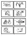
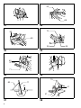
ii)45° bevel angle
Adjust the 45° bevel angle only after performing 0°
bevel angle adjustment. To adjust left 45° bevel
angle, loosen the lever and tilt the blade 45° to the
left. Make sure that the pointer on the arm holder
points to 45° on the bevel scale on the arm holder.
If the pointer does not point to 45°, turn the left 45°
bevel angle adjusting bolt on the side of the arm
holder until the pointer points to 45°. To adjust right
45° bevel angle, perform the same procedure
described above. (Fig. 39)
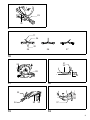
Adjusting for smooth beveling action (Fig. 40)
The hex lock nut holding together the arm and arm
holder has been factory adjusted to assure smooth beveling action and to guarantee precise cutting. Do not
tamper with it. Should looseness develop at the arm and
arm holder connection, tighten the hex lock nut using a
wrench.
ACCESSORIES
CAUTION:
These accessories or attachments are recommended for
use with your Makita tool specified in this manual. The
use of any other accessories or attachments might
present a risk of injury to persons. Only use accessory or
attachment for its stated purpose.
If you need any assistance for more details regarding
these accessories, ask your local Makita service center.
•
•
•
•
•
•
•
•
•
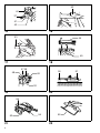
Dust bag
Socket wrench 13
Sub-fence R
Triangular rule
Lock-off button
Vise assembly (horizontal vise)
Vertical vise
Elbow
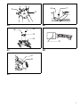
Kerf block
Kerf block (Standard accessory for European
countries) (Fig. 41)
CAUTION:
• When using the kerf block, always cut at the same
miter angle.
• When changing the miter angle, use other kerf blocks.
• When performing bevel cuts, never use the kerf block.
Failure to do so splits the block, causing a serious
injury to operator.
When you use the kerf block at 90° cutting, you can splinter-free cut in workpiece on the side of the guide fence
(height of the workpiece is up to 35 mm). Install the kerf
block onto the guide fence by means of the two screws.
(Adjust the guide fence and the kerf block so that they
contact their faces. Then tighten the screws securely.)
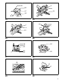
Replacement of carbon brushes
(Fig. 42 & 43)
Replace carbon brushes when they are worn down to the
limit mark. Both identical carbon brushes should be
replaced at the same time.
After use
• After use, wipe off chips and dust adhering to the tool
with a cloth or the like. Keep the safety cover clean
according to the directions in the previously covered
“Safety cover”. Lubricate the sliding portions with tool
oil to prevent rust.
• When storing the tool, pull the carriage toward you fully
so that the slide pole is thoroughly inserted into the turn
base.
To maintain product safety and reliability, repairs, maintenance or adjustment should be carried out by a Makita
Authorized Service Center.
15