1
Functions
Functions
Function selection
occur, especially when high frequencies are
selected. If test circuits having a 50Ω input
impedance are connected, this termination is not
required. In high signal voltage ranges, it should
be noted that the terminating resistor used must
be specified for the power dissipated.
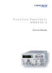
The type of output signal is selected with the
function selection switch . A total number of 4
different waveforms (sine, square, triangle and
pulse) are available. The functions are marked
with the corresponding symbols. If the ONpushbutton
is activated a DC voltage level is
supplied by the HM8030-6 (all function LEDs
off) or superimposed on the output signal, except
in pulse mode.
The max. offset voltage is ±5 V with open outputs
and is continuously adjustable with the OFFSET
control .
In pulse mode no offset voltage is available. With
control pulse width is continuously adjustable
from 10% to 90%. In postition OFF of pushbutton
a fixed pulse width of 50% is delivered.
The output terminal of the HM8030-6 is short
circuit proof. However, if an external DC-voltage
exceeding ±45 V is applied to the output, the
output stage is likely to be destructed. It can
withstand DC-voltage up to ±45 V for a time of
max. 30 seconds.
Frequency adjustment
Trigger output
Coarse adjustment is performed with the range
. The desired frequency is selected by
keys
turning the FREQUENCY control . The selected
frequency appears on the 5-digit display .
In the sine, square and triangle modes, the
supplies a square signal in
trigger output
synchronism with the output signal. An offset
voltage adjusted at the 50Ω output has no
influence upon the trigger signal. The trigger
output is short-circuit-proof and can drive several
TTL inputs. If the trigger output is terminated into
50Ω, the trigger level will fall below TTL
specifications. Therefore short or low-capacity
cables without a 50Ω termination are to be used.
Output amplitude and signal connection
Adaptation in decade steps to the desired
amplitude range is performed by the use of two
attenuators with –20 dB each, which are activated
by pushbuttons
.
Including the continuously adjustable AMPLITUDE control
, the maximum attenuation
amounts to –60dB. With the maximum amplitude
of 10Vpp, the minimum signal voltage to be supplied is about 10mV. These values are obtained
when the generator output is terminated into
50Ω. In the open-circuit condition, the available
signal amplitude is twice as high. Therefore the
maximum output voltage of the output socket is
specified with 20V pp. If exact square-shaped
signals are required, care should be taken that
only 50Ω coaxial cables (e.g. HZ34) are used.
Furthermore, this cable must be terminated into
a 50Ω through-termination (e.g. HZ22). If these
precautions are not observed, overshoot may
If the output of the HM8030-6 unit comes into
contact with components of the circuit under test,
which are carrying DC voltage, an isolation
capacitor of appropriate dielectric strength
should be connected in series with the output of
the generator. The capacitance of this isolating
capacitor should be selected in that way that the
frequency response of the output signal is not
affected over the whole frequency range of the
HM 8030-6 unit.
Sweep facilities
1 st Internal sweep
The internal sweep facility of the HM8030-6
allows checking of filters and equipment in the
frequency range from 3Hz to 10 MHz. Operation
is very easy and does not require more than
setting of the start and stop frequencies and the
sweep time. Activation is by simply pressing the
SWEEP-pushbutton
(START-LED lights) .
Sweep can be combined with all available
functions on the HM8030-6. The start frequency
is automatically given by the settings of the range
selector
and the frequency dial
and is
shown on the 5-digit display. It can be set to any
Subject to change without notice
21