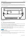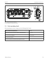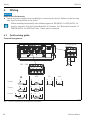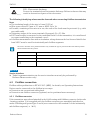
1
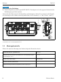
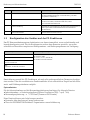
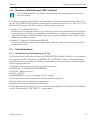
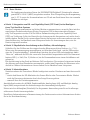
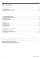
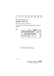
KA00241R/09/A2/14.14 71269524 Products Solutions Services Brief Operating Instructions iTEMP TMT125 DIN rail temperature transmitter With 8 input channels and FOUNDATION Fieldbus™ protocol COM/ ERR CHANNEL ERROR PWR 1: Simulate Enable 2: Write Lock 3-8: Not Used Do not open ! 1 2 3 4 5 6 7 8 CH1 + TMT125 DEVICE ID 452B4810CD-... Made in Singapore 20xx 87484 Nesselwang Order Code: TMT125-XXXXXXXX Ser.No.: 0123456789101 TAG No.: 1019876543210 PTB 05 ATEX xxxx II2 (1G/D)G EEx ia IIC T4 II(1) GD [EEx ia ] IIC inst. per XA056R/09/a3/XX.XX FISCO according to IEC TS 60079-27 -40°C< Ta < 70°C H L - PTB 05 ATEX xxxxX II 3G EEx nA II T4 II 3G EEx nL IIC T4 II (3)G [EEx nL] IIC T4 # Avoid electrostatic charge! 0032 9 ; Temperaturtransmitter (ab Seite 2) < Temperature transmitter (from page 21) Zugehörige Dokumentation finden TMT125 Zugehörige Dokumentation finden Order code 00X00-XXXX0XX0XXX Ser. No.: X000X000000 TAG No.: XXX000 Serial number www.endress.com/deviceviewer 2 Endress+Hauser Operations App Endress+Hauser TMT125 Inhaltsverzeichnis Inhaltsverzeichnis 1 Sicherheitshinweise . . . . . . . . . . . . . . . . . . . . . . . . . . . . . . . . . . . . . . . . . . . . . . . . . . . . . . . . . . . . 4 1.1 1.2 1.3 1.4 Bestimmungsgemäße Verwendung . . . . . . . . . . . . . . . . . . . . . . . . . . . . . . . . . . . . . . . . . . . . . . . . . . . . . . . . . . . . . . . . . . . . . Montage, Inbetriebnahme, Bedienung . . . . . . . . . . . . . . . . . . . . . . . . . . . . . . . . . . . . . . . . . . . . . . . . . . . . . . . . . . . . . . . . . . Betriebssicherheit . . . . . . . . . . . . . . . . . . . . . . . . . . . . . . . . . . . . . . . . . . . . . . . . . . . . . . . . . . . . . . . . . . . . . . . . . . . . . . . . . . . Sicherheitszeichen und -symbole . . . . . . . . . . . . . . . . . . . . . . . . . . . . . . . . . . . . . . . . . . . . . . . . . . . . . . . . . . . . . . . . . . . . . . 4 4 5 6 2 Identifizierung . . . . . . . . . . . . . . . . . . . . . . . . . . . . . . . . . . . . . . . . . . . . . . . . . . . . . . . . . . . . . . . . 6 2.1 Gerätebezeichnung . . . . . . . . . . . . . . . . . . . . . . . . . . . . . . . . . . . . . . . . . . . . . . . . . . . . . . . . . . . . . . . . . . . . . . . . . . . . . . . . . . 6 2.2 Lieferumfang . . . . . . . . . . . . . . . . . . . . . . . . . . . . . . . . . . . . . . . . . . . . . . . . . . . . . . . . . . . . . . . . . . . . . . . . . . . . . . . . . . . . . . . 7 2.3 Zertifikate und Zulassungen . . . . . . . . . . . . . . . . . . . . . . . . . . . . . . . . . . . . . . . . . . . . . . . . . . . . . . . . . . . . . . . . . . . . . . . . . . . 7 3 Montage . . . . . . . . . . . . . . . . . . . . . . . . . . . . . . . . . . . . . . . . . . . . . . . . . . . . . . . . . . . . . . . . . . . . . 8 3.1 3.2 3.3 3.4 3.5 Warenannahme, Transport, Lagerung . . . . . . . . . . . . . . . . . . . . . . . . . . . . . . . . . . . . . . . . . . . . . . . . . . . . . . . . . . . . . . . . . . 8 Montagebedingungen . . . . . . . . . . . . . . . . . . . . . . . . . . . . . . . . . . . . . . . . . . . . . . . . . . . . . . . . . . . . . . . . . . . . . . . . . . . . . . . . 8 Montage Feldgehäuse . . . . . . . . . . . . . . . . . . . . . . . . . . . . . . . . . . . . . . . . . . . . . . . . . . . . . . . . . . . . . . . . . . . . . . . . . . . . . . . . 9 Einbau des für Hutschienen ausgelegten Transmitters . . . . . . . . . . . . . . . . . . . . . . . . . . . . . . . . . . . . . . . . . . . . . . . . . . . . 9 Montagekontrolle . . . . . . . . . . . . . . . . . . . . . . . . . . . . . . . . . . . . . . . . . . . . . . . . . . . . . . . . . . . . . . . . . . . . . . . . . . . . . . . . . . 10 4 Verdrahtung . . . . . . . . . . . . . . . . . . . . . . . . . . . . . . . . . . . . . . . . . . . . . . . . . . . . . . . . . . . . . . . . . 11 4.1 4.2 4.3 4.4 4.5 Verdrahtung auf einen Blick . . . . . . . . . . . . . . . . . . . . . . . . . . . . . . . . . . . . . . . . . . . . . . . . . . . . . . . . . . . . . . . . . . . . . . . . . 11 Feldbusanschluss . . . . . . . . . . . . . . . . . . . . . . . . . . . . . . . . . . . . . . . . . . . . . . . . . . . . . . . . . . . . . . . . . . . . . . . . . . . . . . . . . . . 12 Potenzialausgleich . . . . . . . . . . . . . . . . . . . . . . . . . . . . . . . . . . . . . . . . . . . . . . . . . . . . . . . . . . . . . . . . . . . . . . . . . . . . . . . . . . 15 Schutzart . . . . . . . . . . . . . . . . . . . . . . . . . . . . . . . . . . . . . . . . . . . . . . . . . . . . . . . . . . . . . . . . . . . . . . . . . . . . . . . . . . . . . . . . . . 15 Anschlusskontrolle . . . . . . . . . . . . . . . . . . . . . . . . . . . . . . . . . . . . . . . . . . . . . . . . . . . . . . . . . . . . . . . . . . . . . . . . . . . . . . . . . 16 5 Bedienung und Inbetriebnahme. . . . . . . . . . . . . . . . . . . . . . . . . . . . . . . . . . . . . . . . . . . . . . . . . 17 5.1 5.2 5.3 5.4 5.5 Installationskontrolle . . . . . . . . . . . . . . . . . . . . . . . . . . . . . . . . . . . . . . . . . . . . . . . . . . . . . . . . . . . . . . . . . . . . . . . . . . . . . . . 17 Anzeige- und Bedienelemente . . . . . . . . . . . . . . . . . . . . . . . . . . . . . . . . . . . . . . . . . . . . . . . . . . . . . . . . . . . . . . . . . . . . . . . . 17 Konfiguration des Gerätes und der FF-Funktionen . . . . . . . . . . . . . . . . . . . . . . . . . . . . . . . . . . . . . . . . . . . . . . . . . . . . . . . 18 Hardware-Einstellungen (DIP-Schalter) . . . . . . . . . . . . . . . . . . . . . . . . . . . . . . . . . . . . . . . . . . . . . . . . . . . . . . . . . . . . . . . . 19 Inbetriebnahme . . . . . . . . . . . . . . . . . . . . . . . . . . . . . . . . . . . . . . . . . . . . . . . . . . . . . . . . . . . . . . . . . . . . . . . . . . . . . . . . . . . . 19 Diese Anleitung ist eine Kurzanleitung, sie ersetzt nicht die zum Lieferumfang gehörende Betriebsanleitung. Ausführliche Informationen entnehmen Sie der Betriebsanleitung und den weiteren Dokumentationen. Für alle Geräteausführungen verfügbar über: • Internet: www.endress.com/deviceviewer • Smartphone/Tablet: Endress+Hauser Operations App Endress+Hauser 3 Sicherheitshinweise 1 TMT125 Sicherheitshinweise ! WARNUNG Elektrische Schläge können zum Tod oder zu schweren Körperverletzungen führen. ‣ Gehen Sie mit äußerster Vorsicht vor, falls Sie Kabel und Klemmen berühren. Wenn das Gerät/die Messeinrichtung in einer Hochspannungsumgebung installiert wird und es zu einer Störung oder einem Installationsfehler kommt, kann an den Anschlussklemmen oder dem Gerät/der Messeinrichtung selbst Hochspannung anliegen. 1.1 Bestimmungsgemäße Verwendung • Das 8-Kanal-Gerät überträgt Signale von Widerstandsthermometern (RTD) und Thermoelementen sowie Widerstands- und Millivolt-Signale über FOUNDATION Fieldbus™. Es empfiehlt sich, jeden Kanal individuell zu konfigurieren. • Das Gerät kann auch mit dem FOUNDATION Fieldbus™ H1-Bus eingesetzt werden, der die physische Anordnung gemäß IEC 61158-2/ISA-S50.02-1992 nutzt. • Für Schäden aus unsachgemäßem oder nicht bestimmungsgemäßem Gebrauch haftet der Hersteller nicht. Wenn das Gerät unsachgemäß oder nicht bestimmungsgemäß eingesetzt wird, können Gefahren von ihm ausgehen. 1.2 Montage, Inbetriebnahme, Bedienung Beachten Sie folgende Punkte: • Das Gerät darf nur von qualifiziertem und autorisiertem Fachpersonal (z. B. Elektrofachkraft) unter genauer Beachtung dieser Anleitung, der einschlägigen Normen, der gesetzlichen Vorschriften (länderspezifisch) und der Zertifikate (je nach Ausführung) eingebaut, angeschlossen, in Betrieb genommen und gewartet werden. • Das Fachpersonal muss diese Anleitung gelesen und verstanden haben und die Anweisungen befolgen. Treten Unklarheiten beim Gebrauch der Kurzanleitung auf, muss die Betriebsanleitung benutzt werden. Dort finden sich alle Informationen zum Gerät/Messsystem in ausführlicher Form. • Veränderungen und Reparaturen am Gerät dürfen nicht vorgenommen werden. Ausnahme: Wenn dies in der Betriebsanleitung ausdrücklich erlaubt wird. • Beschädigte Geräte, von denen eine Gefährdung ausgehen könnte, dürfen nicht in Betrieb genommen werden und sind klar und deutlich als defekt zu kennzeichnen. • Beachten Sie grundsätzlich die in Ihrem Land geltenden Vorschriften bezüglich Öffnen und Reparieren von elektrischen Geräten. 4 Endress+Hauser TMT125 1.3 Sicherheitshinweise Betriebssicherheit • Das Gerät ist nach dem Stand der Technik betriebssicher gebaut und geprüft und hat das Werk in sicherheitstechnisch einwandfreiem Zustand verlassen. Die einschlägigen Vorschriften und europäischen Normen sind berücksichtigt. • Beachten Sie die technischen Daten auf dem Typenschild! Das Typenschild befindet sich an der oberen Seite des Gerätes. Explosionsgefährdeter Bereich Bei Einsatz in explosionsgefährdeten Bereichen sind die entsprechenden nationalen Normen einzuhalten. Für Messsysteme, die im explosionsgefährdetem Bereich eingesetzt werden, gilt zusätzlich die separate Ex-Dokumentation. Die darin aufgeführten Installationsvorschriften, Anschlusswerte und Sicherheitshinweise müssen konsequent beachtet werden! • Das Gerät kann in Ex-Bereichen der Kategorie 2G (Zone 1) oder Kategorie 3G (Zone 2) installiert werden. • Bei Anwendungen der Kategorie 2G (Zone 1) entspricht es der Zündschutzart “eigensicher”. Die angeschlossenen Feldgeräte können an Standorten der Kategorie 1G (Zone 0) oder der Kategorie 1D (Zone 20) betrieben werden. • Bei Anwendungen der Kategorie 3G (Zone 2) lautet die Zündschutzart “EEx nA”. Das Gerät kann an ein Segment des Typs “Non IS H1” angeschlossen werden. Unabhängig von der Zündschutzart des H1-Busses sind die Eingänge weiterhin eigensicher. ! VORSICHT Elektrischer Anschluss im explosionsgefährdeten Bereich ‣ Geräte, die in allgemeinen elektrischen Systemen eingesetzt wurden, dürfen danach nicht in elektrischen Systemen betrieben werden, die in Ex-Bereichen angeschlossen sind. Reparaturen Reparaturen, die nicht in der Betriebsanleitung beschrieben sind, dürfen nur direkt beim Hersteller oder durch den Service durchgeführt werden. Störsicherheit Die Messeinrichtung erfüllt die allgemeinen Sicherheitsanforderungen gemäß IEC 61010 und die EMV-Anforderungen gemäß IEC 61326 sowie die NAMUR-Empfehlung NE 21. HINWEIS Spannungsversorgung ‣ Das Gerät muss von einer Spannungsversorgung 9 bis 32 VDC gemäß NEC-Klasse 02 (Niederspannung/-strom) mit Kurzschluss-Leistungsbegrenzung auf 8 A/150 VA gespeist werden. Rücksendung Folgen Sie hierzu den Hinweisen in der Betriebsanleitung. Endress+Hauser 5 Identifizierung 1.4 TMT125 Sicherheitszeichen und -symbole Sicherheitshinweise in dieser Betriebsanleitung sind mit folgenden Sicherheitszeichen und -symbolen gekennzeichnet: Symbol Bedeutung A0011190-DE A0011191-DE A0011192-DE WARNUNG! Dieser Hinweis macht auf eine gefährliche Situation aufmerksam, die, wenn sie nicht vermieden wird, zu Tod oder schwerer Körperverletzung führen kann. VORSICHT! Dieser Hinweis macht auf eine gefährliche Situation aufmerksam, die, wenn sie nicht vermieden wird, zu leichter oder mittelschwerer Körperverletzung führen kann. HINWEIS Dieser Hinweis enthält Informationen zu Vorgehensweisen und weiterführenden Sachverhalten, die keine Körperverletzung nach sich ziehen. ESD - Electrostatic discharge Klemmen vor elektrostatischer Entladung schützen. Ein Nichtbeachten kann zur Zerstörung von Teilen der Elektronik führen. A0012751 2 Identifizierung 2.1 Gerätebezeichnung 2.1.1 Typenschild Das richtige Gerät? Vergleichen und prüfen Sie die Angaben auf dem Typenschild des Gerätes mit den Anforderungen der Messstelle. 6 5 + TMT125 Order Code: TMT125-XXXXXXXX Ser.No.: 0123456789101 TAG No.: 1019876543210 1 DEVICE ID 452B4810CD-... PTB 05 ATEX xxxx II2 (1G/D)G EEx ia IIC T4 II(1) GD [EEx ia ] IIC inst. per XA056R/09/a3/XX.XX FISCO according to IEC TS 60079-27 -40°C< Ta < 70°C H L # Avoid electrostatic charge! 2 Abb. 1: Typenschild des Temperaturtransmitters (Beispiel für ein an einer Hutschiene installiertes Gerät) 6 - PTB 05 ATEX xxxxX II 3G EEx nA II T4 II 3G EEx nL IIC T4 II (3)G [EEx nL] IIC T4 0032 3 4 3 A0006759 Endress+Hauser TMT125 Identifizierung 1 3 TMT125 Order Code: TMT125-XXXXXXXX Ser.No.: 0123456789101 TAG No.: 1019876543210 3 Designed in Germany 6 DEVICE ID 452B4810CD-XXXXXXXXXXX Abb. 2: Typenschild auf dem Feldgehäuse (Beispiel) 1 2 3 4 5 6 2.2 A0006758 Bestellcode, Seriennummer und TAG des Gerätes Umgebungstemperatur Zulassungen mit Symbolen Sensor-Anschlussplan Zulassungen für Ex-Bereiche mit Nummer der zugehörigen Ex-Dokumentation (XA...) ID-Nr. des Gerätes Lieferumfang Der Lieferumfang des Gerätes besteht aus: • Temperaturtransmitter (mit Adapter für Hutschiene oder in einem Feldgehäuse aus Aluminium untergebracht) • Gedruckte, mehrsprachige Kurzanleitung • Lieferschein • Zusätzliche Dokumentation für Geräte, die für den Einsatz im explosionsgefährdeten Bereich (0 2 1) geeignet sind, wie z.B. Sicherheitshinweise (XA...), Control oder Installation Drawings (ZD...). Beachten Sie die Zubehörteile des Gerätes im Kapitel ’Zubehör’ der Betriebsanleitung. 2.3 Zertifikate und Zulassungen CE-Zeichen, Konformitätserklärung Das Gerät hat das Werk in sicherheitstechnisch einwandfreiem Zustand verlassen. Das Gerät berücksichtigt die einschlägigen Normen und Vorschriften nach IEC 61010 “Sicherheitsbestimmungen für elektrische Mess-, Steuer, Regel- und Laborgeräte”. Es erfüllt die gesetzlichen Anforderungen der EU-Richtlinien. Der Hersteller bestätigt die erfolgreiche Prüfung des Gerätes mit der Anbringung des CE-Zeichens. Endress+Hauser 7 Montage TMT125 Gerätezertifizierung FOUNDATION Fieldbus™ Das Gerät erfüllt alle Anforderungen der nachfolgend genannten Spezifikationen: • • • • Zertifiziert nach der Fieldbus-Spezifikation, Revisionsstand 4.61 Geräte-Zertifizierungsnummer: IT035400 Das Gerät erfüllt alle Spezifikationen des FOUNDATION Fieldbus-H1 (www.fieldbus.org) Das Gerät kann auch mit zertifizierten Geräten anderer Hersteller betrieben werden (Interoperabilität) Eine Übersicht über weitere Zulassungen und Zertifizierungen finden Sie in der Betriebsanleitung. 3 Montage 3.1 Warenannahme, Transport, Lagerung 3.1.1 Warenannahme Kontrollieren Sie nach der Warenannahme folgende Punkte: • Sind Verpackung oder Inhalt beschädigt? • Ist die gelieferte Ware vollständig? Vergleichen Sie den Lieferumfang mit Ihrer Bestellung. 3.1.2 Transport und Lagerung Beachten Sie folgende Punkte: • Für Lagerung (und Transport) ist das Gerät stoßsicher zu verpacken. • Die zulässige Lagertemperatur beträgt -40 bis +85 °C (-40 bis +185 °F). 3.2 Montagebedingungen 3.2.1 Abmessungen • Hutschienengehäuse: 217 mm (8,54 in) x 100 mm (3,94 in) x 60 mm (2, 36 in) (BxHxT) • Feldgehäuse: 258 mm (10,16 in) x 140 mm (5,51 in) x 84 mm (3,31 in) (BxHxT) 3.2.2 Montageort • Umgebungstemperatur (für beide Gehäuseausführungen): – Explosionsgefährdeter Bereich: -40 bis +70 °C (-40 bis +158 °F). – Nicht-Explosionsgefährdeter Bereich: -40 bis +85 °C (-40 bis +185 °F). • Relative Luftfeuchtigkeit: 95% nicht kondensierend (gilt für Hutschienenversion) • Klimaklasse: entspricht den Anforderungen der Klasse C1-C3 gemäß IEC 60721-4-3 8 Endress+Hauser TMT125 Montage Das Gerät darf ausschließlich von Fachkräften montiert werden, die speziell dafür geschult wurden. Durch die Technologie vorgegebene, anerkannte Grundsätze und Anforderungen, die die Einrichtung des Gerätes betreffen, sind bei Montage und Demontage zu erfüllen. Besondere Sicherheitsanforderungen sind insbesondere bei Arbeiten an elektrischen Systemen zu beachten. 3.3 Montage Feldgehäuse Das Feldgehäuse erfüllt die Schutzart IP67. Für die Montage sollten 2 Schrauben mit einem Durchmesser von 6 mm verwendet werden. Das Montagematerial ist immer nach der Beschaffenheit der Montageoberfläche (Wand) auszuwählen. Bei der Auswahl des Montagematerials ist darauf zu achten, dass es eine sichere Befestigung des Gerätes gewährleistet. 240 (9.45) A A TMT125 Order Code: TMT125-XXXXXXXX Ser.No.: 0123456789101 TAG No.: 1019876543210 Designed in Germany DEVICE ID 452B4810CD-XXXXXXXXXXX B B Abb. 3: Montage Feldgehäuse A0006835 A: Montagelöcher für die Befestigung mit M6-Schrauben B: Erdungspunkt 3.4 Einbau des für Hutschienen ausgelegten Transmitters Der Transmitter für Hutschienen wurde für den Einbau auf einer Hutschiene von 35 mm gemäß IEC 60715 konzipiert und muss gegen elektrostatische Entladungen geschützt werden. Das Gerät ist in einem Gehäuse unterzubringen, das mindestens folgende Schutzart erfüllt: • IP20 gemäß IEC 60529 oder höher für Anwendungen der Kategorie 2G (Zone 1). Das Gehäuse muss für diese Anwendung geeignet sein. • IP54 gemäß IEC 60529 oder höher für Anwendungen der Kategorie 3G (Zone 2). Das Gehäuse muss für diese Anwendung geeignet sein. Endress+Hauser 9 Montage TMT125 HINWEIS Elektrostatische Entladung ‣ Kunststoffgehäuse müssen gemäß IEC 60079-0 konzipiert sein oder gegen elektrostatische Entladungen geschützt werden. Lassen Sie das Gerät nun auf die Hutschiene aufschnappen, indem Sie es zuerst in die Hutschiene einhängen und es dann vorsichtig andrücken, bis es einrastet ( å 4, Schritt 1 und 2). A COM/ ERR CHANNEL ERROR PWR 1: Simulate Enable 2: Write Lock 3-8: Not Used Do not open ! 2 3 4 5 6 7 8 + TMT125 Order Code: TMT125-XXXXXXXX Ser.No.: 0123456789101 TAG No.: 1019876543210 DEVICE ID 452B4810CD-... PTB 05 ATEX xxxx II2 (1G/D)G EEx ia IIC T4 II(1) GD [EEx ia ] IIC inst. per XA056R/09/a3/XX.XX FISCO according to IEC TS 60079-27 -40°C< Ta < 70°C H L - PTB 05 ATEX xxxxX II 3G EEx nA II T4 II 3G EEx nL IIC T4 II (3)G [EEx nL] IIC T4 # Avoid electrostatic charge! 0032 1 A0006837 Abb. 4: Einbau des für Hutschienen ausgelegten Transmitters A: Hutschiene von 35 mm gemäß IEC 60715 3.5 Montagekontrolle Führen Sie nach der Montage des Gerätes folgende Kontrollen durch: 10 Gerätezustand und -spezifikationen Hinweise Entspricht die Messstelle den Spezifikationen, wie Umgebungstemperatur, Montageort, usw.? ä8 Ist das Gerät unbeschädigt? Sichtkontrolle Ist die IP-Schutzart gewährleistet? - Sind die Montageschrauben (Feldgehäuse) sicher festgezogen? - Endress+Hauser TMT125 4 Verdrahtung Verdrahtung HINWEIS Zerstörung der Elektronik ‣ Gerät nicht unter Betriebsspannung installieren bzw. verdrahten. Bei der Installation von eigensicheren Feldbus-Segmenten ist die EN 60079-14/IEC 60079-14 zu beachten. In der Bundesrepublik Deutschland muss darüber hinaus auch das “National Foreword” der DIN EN 60079-14/VDE 0165 Part 1 beachtet werden. 4.1 Verdrahtung auf einen Blick Klemmenbelegung COM/ ERR CHANNEL ERROR PWR 2 3 4 5 8 7 6 CH1 1 FOUNDATION FieldbusTM 1: Simulate Enable 2: Write Lock 3-8: Not Used Do not open ! S + - PTB 05 ATEX xxxx II2 (1G/D)G EEx ia IIC T4 II(1) GD [EEx ia ] IIC # inst. per XA056R/09/a3/XX.XX FISCO according to IEC TS 60079-27 -40°C< Ta < 70°C Avoid electrostatic charge! 0032 Order Code: TMT125-XXXXXXXX Ser.No.: 0123456789101 TAG No.: 1019876543210 L PTB 05 ATEX xxxxX II 3G EEx nA II T4 II 3G EEx nL IIC T4 II (3)G [EEx nL] IIC T4 DEVICE ID 452B4810CD-... TMT125 H CH1...CH8 H L TC RTD Ω H mV L H L 2-Leiter 4-Leiter L L 3-Leiter H L H L Abb. 5: Anschlussklemmenbelegung des Temperaturtransmitters Endress+Hauser A0006330-DE 11 Verdrahtung A0012751 TMT125 ESD - Electrostatic discharge Schützen Sie die Klemmen vor elektrostatischer Entladung. Ein Nichtbeachten kann zur Zerstörung von Teilen der Elektronik führen. Die nachfolgenden ID-Werte sind bei der Verschaltung der Feldbus-Übertragungsleitung zu beachten: • Die Isolierlänge des Drahtes beträgt 9 mm (0,35 in). • Leitungsquerschnitt: 0,2 mm bis 2,5 mm oder AWG 24 bis 14. • Wird ein Kabel aus Feindraht verwendet, müssen die Leitungsenden geschützt werden (z. B. mit Aderendhülsen). • Anziehdrehmoment der Schraubklemmen: 0,4...0,5 Nm. • Wird ein Thermoelement an die Klemmen H und L des Transmitters angeschlossen, müssen die Klemmen + und - unbelegt bleiben. • Für eigensichere Feldbussegmente muss eine Feldbus-Übertragungsleitung mit einer Isolationsspannung von mindestens 500 V zwischen Busleitung und Schirmung verwendet werden. Die Serviceschnittstelle dient nur zur Parametrierung. Sie erfüllt die Zündschutzart EEx ia IIC/IIB bzw. EEx ib IIC/IIB mit folgenden Werten: UO = 7,2 V Kalibrierkurve: linear IO = 29,1 mA Nur für den Anschluss von eigensicheren Stromkreisen PO = 52,38 mW Ui = 5 V Li = 0 Ci = 0 HINWEIS Serviceschnittstelle ‣ Über die Serviceschnittstelle durchzuführende Parametrieraufgaben dürfen ausschließlich von Endress+Hauser Servicemitarbeitern durchgeführt werden! 4.2 Feldbusanschluss Feldbus-Kabelspezifikation nach IEC 61158-2 (MBP), Details siehe Betriebsanleitung. Der Anschluss von Geräten an den Feldbus kann auf zwei Arten erfolgen: • Über herkömmliche Kabelverschraubung • Über Feldbus-Gerätestecker (optional, als Zubehör erhältlich) 4.2.1 Feldbus-Gerätestecker Wurde der Transmitter in der Ausführung mit Feldgehäuse und Feldbus-Gerätestecker bestellt (Bestellcode È Gehäuse: Position 3), ist der Feldbus-Gerätestecker bei Auslieferung werksseitig vormontiert und verdrahtet. Abschirmung und Erde (Pin 3 und 4) werden an Klemme S des eigensicheren Feldbus-Segmentes angeschlossen. ( å 5) 12 Endress+Hauser TMT125 Verdrahtung 4.2.2 Kabelverschraubung oder -durchführung • Ist das Gerät nicht aufgrund der Montage des Gehäuses geerdet, wird die Erdung über eine der Erdungsschrauben empfohlen. Das Erdungskonzept der Anlage ist zu beachten! Die Kabelschirmung zwischen dem abisolierten Feldbuskabel und der Erdklemme sollte so kurz wie möglich gehalten werden. • Beschädigungsgefahr des Feldbuskabels! – In Anlagen ohne zusätzlichen Potentialausgleich können, falls der Schirm des Feldbuskabels an mehreren Stellen geerdet wird, netzfrequente Ausgleichströme auftreten, welche das Kabel bzw. den Schirm beschädigen. Der Schirm des Feldbuskabels ist in solchen Fällen nur einseitig zu erden, d.h. er darf nicht mit der Erdungsklemme des Gehäuses verbunden werden. Der nicht angeschlossene Schirm ist zu isolieren! – Es ist nicht empfehlenswert, den Feldbus über herkömmliche Kabelverschraubungen anzuschließen. Falls Sie später auch nur ein Gerät austauschen, muss die Buskommunikation unterbrochen werden. • Die Klemmen für den Feldbusanschluss verfügen über einen integrierten Verpolungsschutz. – Leitungsquerschnitt: max. 2,5 mm2 • Für den Anschluss ist grundsätzlich ein abgeschirmtes Kabel zu verwenden. Anziehdrehmoment für die Kabelverschraubungen (Feldgehäuse): Das Anziehdrehmoment der Überwurfmuttern richtet sich nach dem Typ des verwendeten Kabels und ist daher vom Benutzer zu ermitteln. Die Überwurfmuttern müssen sicher festgezogen werden. Ein zu festes Anziehen der Überwurfmuttern kann negative Auswirkungen auf die Schutzart haben. Folgende Spezifikation kann als Richtwert herangezogen werden: Typ Überwurfmutter Unterteil Einbau des Temperaturtransmitters im Feldgehäuse 4,17 Nm 6,25 Nm Nur permanent verlegte Kabel und Leitungen in die Kabelverschraubungen einführen. Die zulässigen Kabeldurchmesser finden Sie in den technischen Daten der Betriebsanleitung. Der Bediener muss eine geeignete Zugentlastungsklemme vorsehen (z. B. mit einer passenden Kabelschelle). Die Montagebedingungen ä 8 sind einzuhalten. Nicht verwendete Kabelverschraubungen müssen mit einem entsprechenden Blindstopfen verschlossen oder durch einen geeigneten Schraubverschluss ersetzt werden. Die erforderliche Schutzart (IP67) ist einzuhalten. Endress+Hauser 13 Verdrahtung TMT125 • Der Umgebungstemperaturbereich kann durch den Blindstopfen beschränkt werden. Beispiele für Blindstopfen und Schraubverschlüsse finden Sie in entsprechenden Datenblättern. • Bei Metallgehäusen in Ex-Bereichen ist ein geeigneter Potenzialausgleich gemäß IEC 60079 erforderlich. Zu diesem Zweck steht auf dem Gehäuse eine Erdungsschraube zur Verfügung ( å 3, Pos. B). Der Anschluss muss dafür ausgelegt sein, eine Selbstsperrung zu verhindern und muss gegen Korrosion geschützt sein. Korrosionsschutz kann z. B. auch durch Verwendung von verzinnten Kabelplatten erreicht werden. • Vor dem Schließen der Abdeckung ist eine Sichtprüfung durchzuführen, um sicherzustellen, dass die Dichtung der Abdeckung keine sichtbaren Anzeichen einer Beschädigung aufweist. Im Fall einer Beschädigung muss die Dichtung durch eine neue Originaldichtung ersetzt werden. Die Schrauben auf der Abdeckung sollten mit einem Anziehdrehmoment von 2,5 Nm festgezogen werden. Handhabung der Kabelverschraubung Bus Bus + - S + - S Bus Bus + - S + - S 120 mm (4.7 in) A B 3-4 mm (0.12-0.16 in) Abb. 6: Handhabung der Kabelverschraubung A0019055 Pos. A: Inneres Kunststoffelement Pos. B: O-Ring 1. 14 Ummantelung des Kabels auf bis zu 120 mm (4,7 in) abisolieren. Endress+Hauser TMT125 2. 3. Verdrahtung Überwurfmuttern vom Feldgehäuse lösen und auf das Kabel schieben. Ebenso inneres Kunststoffelement aus dem Unterteil der Kabelverschraubung entfernen und auf das Kabel schieben. Inneres Kunststoffelement ausreichend weit über das Kabel schieben, sodass die Ummantelung vollständig umgeben ist. Ummantelung darf nicht über das Ende des inneren Kunststoffelementes hinausragen. Abschirmung über das innere Kunststoffelement ziehen und auf die korrekte Länge kürzen. Abschirmung sollte rund 3 bis 4 mm (0,12 bis 0,16 in) über den O-Ring überstehen. Kabel mit innerem Kunststoffelement in das Unterteil der Kabelverschraubung einführen. Überwurfmutter festziehen. Das Anziehdrehmoment der Überwurfmuttern richtet sich nach dem Typ des verwendeten Kabels und ist daher vom Benutzer zu ermitteln. Richtwerte ä 13. 4. 5. 6. 4.3 Potenzialausgleich HINWEIS Abschirmung und Erdung des Transmitters ‣ Wird die Abschirmung der Feldbus-Übertragungsleitung aus Gründen der elektromagnetischen Verträglichkeit geerdet, sind immer die Abschnitte 12.2.2.3 der IEC 60079-14 sowie 6.2 und 6.3 des FOUNDATION Fieldbus™ Application Guide 31.35 bit/s Intrinsically Safe Systems zu beachten. Für den Anschluss der Klemme S des eigensicheren Feldbus-Segmentes gilt: • Wird die Ausführung mit Feldgehäuse verwendet, so wird die Klemme S intern im Gehäuse angeschlossen. Das Gehäuse sollte an den Potentialausgleich angeschlossen sein. ! VORSICHT Ausführung mit Feldgehäuse Bei dieser Ausführung muss das Gehäuse an den Potenzialausgleich angeschlossen werden, wenn es sich um Anwendungsbereiche der Kategorie 2G (Zone 1) handelt. ‣ • Wird die Ausführung mit Hutschiene verwendet, so wird die Klemme S intern an die Hutschiene angeschlossen. Die Hutschiene sollte an den Schaltschrank angeschlossen werden und dieser wiederum an den Potenzialausgleich. Abhängig hiervon wird die Abschirmung automatisch an den Potenzialausgleich angeschlossen. Projektierungsangaben über den Feldbus entnehmen Sie der Betriebsanleitung BA00062S/04/en “Guideline FOUNDATION Fieldbus™ Function Blocks”. 4.4 Schutzart In der Ausführung mit Feldgehäuse erfüllt das Gerät die Anforderungen der Schutzart IP67. Damit die Schutzart IP67 auch nach dem Einbau oder nach Servicearbeiten erfüllt wird, müssen folgende Punkte berücksichtigt werden: Endress+Hauser 15 Verdrahtung TMT125 • Die Gehäusedichtungen müssen sauber und unverletzt in die Dichtungsnut eingelegt werden. Gegebenenfalls sind die Dichtungen zu trocknen, zu reinigen oder zu ersetzen. • Sämtliche Gehäuseschrauben und Schraubdeckel müssen fest angezogen sein. • Die für den Anschluss verwendeten Kabel müssen den spezifizierten Außendurchmesser aufweisen (z.B. M20 x 1,5, Kabeldurchmesser 8 bis 12 mm). • Kabeleinführung fest anziehen ( å 7). • Kabel vor der Kabeleinführung in einer Schlaufe verlegen (“Wassersack”, å 7). Auftretende Feuchtigkeit kann so nicht zur Einführung gelangen. Montieren Sie das Gerät möglichst so, dass die Kabeleinführungen nicht nach oben gerichtet sind. • Nicht benutzte Kabeleinführungen sind durch einen Blindstopfen zu ersetzen. • Die verwendete Schutztülle darf nicht aus der Kabeleinführung entfernt werden. Abb. 7: Anschlusshinweise zur Einhaltung der Schutzart IP67 4.5 Anschlusskontrolle Führen Sie nach der Installation und vor der elektrischen Inbetriebnahme des Gerätes folgende Kontrollen durch: Gerätezustand und -spezifikationen Hinweise Sind Gerät oder Kabel unbeschädigt? Sichtkontrolle Elektrischer Anschluss Hinweise Stimmt die Versorgungsspannung mit der Gerätespezifikation überein? 9 bis 32 V DC Erfüllen die verwendeten Kabel die FF-Spezifikationen? siehe Betriebsanleitung Sind die montierten Kabel von Zug entlastet? - Sind Hilfsenergie-/Feldbuskabel korrekt angeschlossen? ä 11 Sind alle Anschlussklemmen fest angezogen? - Sind alle Kabelverschraubungen montiert, fest angezogen und dicht? Kabelführung mit “Wassersack”? ä 13 und ä 15 Sind alle Gehäusedeckel montiert und fest angezogen? - Elektrischer Anschluss FOUNDATION Fieldbus™ Hinweise 16 Endress+Hauser TMT125 Bedienung und Inbetriebnahme Sind alle Anschlusskomponenten (T-Abzweiger, Anschlussboxen, Gerätestecker, usw.) korrekt miteinander verbunden? - Wurde jedes Feldbussegment beidseitig mit einem Busabschluss terminiert? - Wurde die max. Länge der Feldbus- und Stichleitung gemäß den FOUNDATION Fieldbus™- Spezifikationen eingehalten? - Ist das Feldbuskabel lückenlos abgeschirmt und korrekt geerdet? - 5 Bedienung und Inbetriebnahme 5.1 Installationskontrolle Vor der ersten Inbetriebnahme vergewissern Sie sich bitte, dass: • das Gerät korrekt montiert wurde • der elektrische Anschluss richtig ist. 5.2 Anzeige- und Bedienelemente 6 4 1 2 3 COM/ ERR CHANNEL ERROR 5 PWR 1: Simulate Enable 2: Write Lock 3-8: Not Used Do not open ! 3 2 4 5 6 7 8 CH1 1 + Order Code: TMT125-XXXXXXXX Ser.No.: 0123456789101 TAG No.: 1019876543210 DEVICE ID 452B4810CD-... PTB 05 ATEX xxxx II2 (1G/D)G EEx ia IIC T4 II(1) GD [EEx ia ] IIC inst. per XA056R/09/a3/XX.XX FISCO according to IEC TS 60079-27 -40°C< Ta < 70°C H L - PTB 05 ATEX xxxxX II 3G EEx nA II T4 II 3G EEx nL IIC T4 II (3)G [EEx nL] IIC T4 # Avoid electrostatic charge! 0032 TMT125 A0006341 Abb. 8: Anzeige- und Bedienelemente des Transmitters Pos.-nr. Funktion Beschreibung 1 Grüne LED leuchtet kontinuierlich Signalisiert “Netz ein” 2 Rote LED leuchtet kontinuierlich oder blinkt Signalisiert Kommunikationsstatus: Hardware- oder Kommunikationsfehler Endress+Hauser 17 Bedienung und Inbetriebnahme TMT125 Pos.-nr. Funktion Beschreibung 3 rot blinkende LEDs Signalisiert Status des angeschlossenen Sensors: Sensorfehler (Bereichsüberschreitung/-unterschreitung, Verdrahtungsfehler, Kabelbruch) 4 DIP-Schalter Schalter für Hardware-Einstellungen (nur Schalter 1 und 2 werden verwendet): Simulation EIN/AUS; Hardware-Schreibschutz EIN/AUS 5 Trennvorrichtung Erforderlich zur Installation in Ex-Bereichen der Kategorie 3 (siehe gesonderte Sicherheitshinweise zum Einsatz in Ex-Bereichen) 6 Serviceschnittstelle Nur für Endress+Hauser Service 5.3 Konfiguration des Gerätes und der FF-Funktionen Das FF-Kommunikationssystem funktioniert nur dann einwandfrei, wenn es fachkundig und korrekt konfiguriert wird. Für die Konfiguration stehen dem Benutzer spezielle, von unterschiedlichen Herstellern angebotene Konfigurations- und Bedienprogramme zur Verfügung. Prozessleitsysteme Asset Management Systeme Endress+Hauser ControlCare • • • • Emerson DeltaV Yokogawa Centum CS3000/VP National Instruments NI-Configurator Emerson AMS FC375, FC475 (Handheld) Endress+Hauser Fieldcare ABB: AC800 XA, AC800 M, Freelance Honeywell PKS Experion Foxboro Invensys I/A Series Damit können sowohl die FF-Funktionen, als auch alle gerätespezifischen Parameter konfiguriert werden. Über die vordefinierten Funktionsblöcke ist ein einheitlicher Zugriff auf alle Netzwerk- und Feldbusgerätedaten möglich. Systemdateien Für die Inbetriebnahme und die Netzwerkprojektierung benötigen Sie folgende Dateien: • Inbetriebnahme Gerätebeschreibung (Device Description (DD): *.sym, *.ffo) • Netzwerkprojektierung *.CFF-Datei (Common File Format) Diese Dateien können wie folgt bezogen werden: • Kostenlos über das Internet: www.endress.com • Über die FOUNDATION Fieldbus™-Organisation: www.fieldbus.org 18 Endress+Hauser TMT125 5.4 Bedienung und Inbetriebnahme Hardware-Einstellungen (DIP-Schalter) Der Simulationsmodus über Hardwareeinstellung hat Priorität gegenüber der Softwareeinstellung. Über Miniaturschalter (DIP-Schalter) am Transmitter können folgende Hardware-Einstellungen für die FOUNDATION Fieldbus™-Schnittstelle vorgenommen werden ( å 8, Pos. 4). Es gibt acht DIP-Schalter. Nur DIP-Schalter 1 und 2 werden verwendet. • Schalter 1: Simulation EIN/AUS Bei aktivierter Simulation kann der vom Transducer Block zum Funktionsblock übertragene Sensoreingang vom Leitsystem unabhängig vom Hardware-Eingang eines Eingangskanals eingestellt werden. Aus Sicherheitsgründen wird dringend empfohlen, den Schalter im Normalbetrieb auf AUS zu stellen. • Schalter 2: Hardware-Schreibschutz EIN/AUS Ist der Schreibschutz aktiviert (Einstellung EIN), kann das Gerät nicht länger über den Bus parametriert werden. 5.5 Inbetriebnahme 5.5.1 Identifizierung, Gerätekennung, PD Tag Die Identifizierung des Gerätes erfolgt beim FOUNDATION Fieldbus™ im Host- oder Konfigurationssystem über die Gerätekennung (DEVICE_ID). Die DEVICE_ID ist eine Kombination aus Herstellerkennung, Gerätetyp und Geräte-Seriennummer. Sie ist eindeutig und kann niemals doppelt vergeben werden. Die DEVICE_ID des Gerätes setzt sich wie folgt zusammen: • DEVICE_ID = 452B4810CD-XXXXXXXXXXX • 452B48 = Endress+Hauser • 10CD = TMT125 • XXXXXXXXXXX = Geräte-Seriennummer (11-stellig) Die Seriennummer wird ebenfalls auf dem Typenschild angegeben: • auf der Oberseite des Hutschienentransmitters • auf der Oberseite der Feldgehäuseabdeckung. Die Messstellenbezeichnung (PD_TAG) enthält standardmäßig eine Gerätekennung in Klartext und die Seriennummer: “EH_TMT125_ xxxxxxxxxxx”. Endress+Hauser 19 Bedienung und Inbetriebnahme TMT125 5.5.2 Erste Schritte Die funktionstechnischen Daten der FOUNDATION Fieldbus™-Schnittstelle müssen gemäß IEC 61158-2 (MBP) eingehalten werden. Eine Überprüfung der Busspannung von 9...32 V sowie der Stromaufnahme von 23 mA am Gerät kann über ein normales Multimeter erfolgen. • Schritt 1: Integration von DD- und Capability-Datei (CFF-Datei) in das Konfigurations-Tool des Host-Systems Um den Temperaturtransmitter im Online-Modus zu parametrieren, muss die Datei mit der zugehörigen Gerätebeschreibung (Device Description, DD) in das verwendete Engineering-Tool importiert werden. Für die Offline-Parametrierung steht eine Capability-Datei (CFF) zur Verfügung. Sollte der Hersteller des Leitsystems die Integration noch nicht durchgeführt haben, finden Sie die notwendigen Dateien im Internet unter www.endress.com oder www.fieldbus.org. Im Handbuch zum Leitsystem finden Sie Anweisungen dazu, wie die Dateien importiert werden. • Schritt 2: Physikalische Anschaltung an den Feldbus, Adressbelegung Schließen Sie den Feldbus an die entsprechenden Klemmen auf dem Gerät an ( ä 11). Wenn eine Stromversorgung angeschlossen ist, fährt das Gerät hoch, und die LEDs zeigen eine Art “Fortschrittsbalken”. Anschließend leuchtet die grüne LED und signalisiert damit “Netz ein”, während die LEDs für eventuelle Sensorfehler ausgeschaltet sind. Die Kommunikations-LED ( å 8, Pos. 2) blinkt rot, bis die Kommunikation zu einem Link Master aufgebaut ist. Bei Auslieferung ist das Gerät auf Adresse 245 konfiguriert. Die meisten Leitsysteme ändern die Adresse nach dem Einschalten automatisch, sodass kein Eingreifen des Benutzers erforderlich ist. Nähere Informationen hierzu finden Sie im Handbuch zum Leitsystem. • Schritt 3: Inbetriebnahme Zunächst müssen die Transducer-Blöcke konfiguriert werden. Dies kann auf zwei Arten erfolgen: – durch Ausführen der DD-Methoden des Sensor Blocks oder Concentrator Blocks. Hierbei wird der Benutzer schrittweise durch den Setup-Prozess geleitet. – manuell über die Funktionsparameter. Anschließend werden die AI/MAI-Funktionsblöcke Analog Input (AI) und Multiple Analog Input (MAI) entsprechend den Anforderungen der Anwendung konfiguriert. Zuletzt wird ein Ablaufplan (Schedule) für die gesamte Anwendung erstellt und in alle angeschlossenen Geräte heruntergeladen. Detaillierte Informationen zur Parametrierung des Gerätes sowie weitere Informationen finden Sie in der Betriebsanleitung. 20 Endress+Hauser TMT125 How to find the documentation for your device How to find the documentation for your device Order code 00X00-XXXX0XX0XXX Ser. No.: X000X000000 TAG No.: XXX000 Serial number www.endress.com/deviceviewer Endress+Hauser Endress+Hauser Operations App 21 Table of contents TMT125 Table of contents 1 Safety instructions . . . . . . . . . . . . . . . . . . . . . . . . . . . . . . . . . . . . . . . . . . . . . . . . . . . . . . . . . . . .23 1.1 1.2 1.3 1.4 Designated use . . . . . . . . . . . . . . . . . . . . . . . . . . . . . . . . . . . . . . . . . . . . . . . . . . . . . . . . . . . . . . . . . . . . . . . . . . . . . . . . . . . . . Installation, commissioning and operation . . . . . . . . . . . . . . . . . . . . . . . . . . . . . . . . . . . . . . . . . . . . . . . . . . . . . . . . . . . . . Operational safety . . . . . . . . . . . . . . . . . . . . . . . . . . . . . . . . . . . . . . . . . . . . . . . . . . . . . . . . . . . . . . . . . . . . . . . . . . . . . . . . . . Notes on safety conventions and icons . . . . . . . . . . . . . . . . . . . . . . . . . . . . . . . . . . . . . . . . . . . . . . . . . . . . . . . . . . . . . . . . . 23 23 23 25 2 Identification . . . . . . . . . . . . . . . . . . . . . . . . . . . . . . . . . . . . . . . . . . . . . . . . . . . . . . . . . . . . . . . . .25 2.1 Device designation . . . . . . . . . . . . . . . . . . . . . . . . . . . . . . . . . . . . . . . . . . . . . . . . . . . . . . . . . . . . . . . . . . . . . . . . . . . . . . . . . . 25 2.2 Scope of delivery . . . . . . . . . . . . . . . . . . . . . . . . . . . . . . . . . . . . . . . . . . . . . . . . . . . . . . . . . . . . . . . . . . . . . . . . . . . . . . . . . . . 26 2.3 Certificates and approvals . . . . . . . . . . . . . . . . . . . . . . . . . . . . . . . . . . . . . . . . . . . . . . . . . . . . . . . . . . . . . . . . . . . . . . . . . . . 26 3 Installation instructions . . . . . . . . . . . . . . . . . . . . . . . . . . . . . . . . . . . . . . . . . . . . . . . . . . . . . . . .27 3.1 3.2 3.3 3.4 3.5 Incoming acceptance, transport, storage . . . . . . . . . . . . . . . . . . . . . . . . . . . . . . . . . . . . . . . . . . . . . . . . . . . . . . . . . . . . . . . Mounting conditions . . . . . . . . . . . . . . . . . . . . . . . . . . . . . . . . . . . . . . . . . . . . . . . . . . . . . . . . . . . . . . . . . . . . . . . . . . . . . . . . Field housing mounting . . . . . . . . . . . . . . . . . . . . . . . . . . . . . . . . . . . . . . . . . . . . . . . . . . . . . . . . . . . . . . . . . . . . . . . . . . . . . Mounting of the DIN rail transmitter . . . . . . . . . . . . . . . . . . . . . . . . . . . . . . . . . . . . . . . . . . . . . . . . . . . . . . . . . . . . . . . . . . Post-mounting check . . . . . . . . . . . . . . . . . . . . . . . . . . . . . . . . . . . . . . . . . . . . . . . . . . . . . . . . . . . . . . . . . . . . . . . . . . . . . . . 27 27 28 28 29 4 Wiring . . . . . . . . . . . . . . . . . . . . . . . . . . . . . . . . . . . . . . . . . . . . . . . . . . . . . . . . . . . . . . . . . . . . . .30 4.1 4.2 4.3 4.4 4.5 Quick wiring guide . . . . . . . . . . . . . . . . . . . . . . . . . . . . . . . . . . . . . . . . . . . . . . . . . . . . . . . . . . . . . . . . . . . . . . . . . . . . . . . . . . Fieldbus connection . . . . . . . . . . . . . . . . . . . . . . . . . . . . . . . . . . . . . . . . . . . . . . . . . . . . . . . . . . . . . . . . . . . . . . . . . . . . . . . . . Potential equalization . . . . . . . . . . . . . . . . . . . . . . . . . . . . . . . . . . . . . . . . . . . . . . . . . . . . . . . . . . . . . . . . . . . . . . . . . . . . . . . Degree of protection . . . . . . . . . . . . . . . . . . . . . . . . . . . . . . . . . . . . . . . . . . . . . . . . . . . . . . . . . . . . . . . . . . . . . . . . . . . . . . . . Post-connection check . . . . . . . . . . . . . . . . . . . . . . . . . . . . . . . . . . . . . . . . . . . . . . . . . . . . . . . . . . . . . . . . . . . . . . . . . . . . . . 30 31 34 34 35 5 Operation and commissioning . . . . . . . . . . . . . . . . . . . . . . . . . . . . . . . . . . . . . . . . . . . . . . . . . .36 5.1 5.2 5.3 5.4 5.5 Function check . . . . . . . . . . . . . . . . . . . . . . . . . . . . . . . . . . . . . . . . . . . . . . . . . . . . . . . . . . . . . . . . . . . . . . . . . . . . . . . . . . . . . Display and operating elements . . . . . . . . . . . . . . . . . . . . . . . . . . . . . . . . . . . . . . . . . . . . . . . . . . . . . . . . . . . . . . . . . . . . . . Configuration of the device and FF functions . . . . . . . . . . . . . . . . . . . . . . . . . . . . . . . . . . . . . . . . . . . . . . . . . . . . . . . . . . . Hardware settings (DIP switches) . . . . . . . . . . . . . . . . . . . . . . . . . . . . . . . . . . . . . . . . . . . . . . . . . . . . . . . . . . . . . . . . . . . . . Commissioning . . . . . . . . . . . . . . . . . . . . . . . . . . . . . . . . . . . . . . . . . . . . . . . . . . . . . . . . . . . . . . . . . . . . . . . . . . . . . . . . . . . . 36 36 37 38 38 These Instructions are Brief Operating Instructions; they are not a substitute for the Operating Instructions pertaining to the device. For detailed information, refer to the Operating Instructions and other documentation. Available for all device versions via: • Internet: www.endress.com/deviceviewer • Smart phone/Tablet: Endress+Hauser Operations App 22 Endress+Hauser TMT125 1 Safety instructions Safety instructions ! WARNING Electric shocks can cause death or serious injury ‣ Proceed with extreme caution when working with cables and terminals. If the device/measuring system is installed in a high-voltage environment and a malfunction or installation error occurs, high voltage can be present at the terminals or the device/measuring system itself. 1.1 Designated use • The 8 channel device transfers signals from resistance temperature measuring sensors (RTDs), thermocouples (TCs), resistance and millivolt signals via FOUNDATION Fieldbus™. Each channel could be configured independently. • The device can be used for FOUNDATION Fieldbus™ H1 bus that use the physical layout in accordance with IEC 61158-2/ISA-S50.02-1992. • The manufacturer cannot be held responsible for damage caused by misuse of the unit. The device can, however, be a source of danger if used incorrectly or for anything other than the designated use. 1.2 Installation, commissioning and operation Note the following points: • The device may only be installed, connected, commissioned and maintained by properly qualified and authorized staff (e.g. electrical technicians) in strict compliance with these Operating Instructions, the applicable, country-specific standards, legal regulations and certificates (depending on the application). • The specialist staff must have read and understood these Brief Operating Instructions and must follow the instructions they contain. If any areas are unclear in the Brief Operating Instructions, you must use the Operating Instructions which contain detailed information on the device/measuring system. • Modifications and repairs are not permitted on the device unless explicitly permitted by the Operating Instructions. • Damaged devices which could constitute a source a danger must not be put into operation and must be clearly indicated as defective. • Invariably, local regulations governing the opening and repair of electrical devices apply. 1.3 Operational safety • The device is designed to meet state-of-the-art safety requirements, has been tested and left the factory in a condition in which it is safe to operate. Applicable regulations and European standards have been taken into consideration. • Please pay particular attention to the technical data on the nameplate! The nameplate is located on the upper side of the device. Endress+Hauser 23 Safety instructions TMT125 Hazardous areas When using in hazardous areas, the national safety requirements must be met. Separate Ex documentation applies to measuring systems that are used in hazardous areas. Strict compliance with the installation instructions, ratings and safety instructions as listed in this supplementary documentation is mandatory. The documentation number of this document (XA) is also indicated on the nameplate. • The device may be installed in category 2G (Zone 1) or category 3G (Zone 2) of a hazardous area. • For category 2G (Zone 1) applications the type of protection is “Intrinsic Safety”. The associated field devices could operate in a category 1G (Zone 0) or category 1D (Zone 20) location. • For category 3G (Zone 2) applications the type of protection is EEx nA. The device could be connected to Non IS H1 segment. Independent of the type of protection of the H1 bus the inputs remains intrinsically safe. ! CAUTION Electrical connection in hazardous areas ‣ Devices that are operated in general electrical systems must not thereafter be operated in electrical systems that are connected in hazardous areas. Repairs Repairs that are not described in the Operating Instructions may only be carried out directly at the manufacturer's site or by the service team. Electromagnetic compatibility The measuring system complies with the general safety requirements in accordance with IEC 61010 and the EMC requirements of IEC 61326 and NAMUR Recommendation NE 21. NOTICE Power supply ‣ Power must be supplied to the device from a 9 to 32 VDC power supply in accordance with NEC Class 02 (low voltage/current) with short-circuit power limitation to 8 A/150 VA. Return Follow the instructions on returning the device as outlined in the Operating Instructions. 24 Endress+Hauser TMT125 1.4 Identification Notes on safety conventions and icons Always refer to the safety instructions in these Operating Instructions labelled with the following symbols: Symbol Meaning A0011190-EN WARNING! This symbol alerts you to a dangerous situation. Failure to avoid this situation can result in serious or fatal injury. A0011191-EN CAUTION! This symbol alerts you to a dangerous situation. Failure to avoid this situation can result in minor or medium injury. A0011192-EN NOTICE This symbol contains information on procedures and other facts which do not result in personal injury. ESD - Electrostatic discharge Protect the terminals against electrostatic discharge. Failure to comply with this instruction can result in the destruction of parts of the electronics. A0012751 2 Identification 2.1 Device designation 2.1.1 Nameplate The right device? Compare and check the details on the nameplate of the DIN rail or field housing device against the measuring point requirements. 6 5 + TMT125 Order Code: TMT125-XXXXXXXX Ser.No.: 0123456789101 TAG No.: 1019876543210 1 DEVICE ID 452B4810CD-... PTB 05 ATEX xxxx II2 (1G/D)G EEx ia IIC T4 II(1) GD [EEx ia ] IIC inst. per XA056R/09/a3/XX.XX FISCO according to IEC TS 60079-27 -40°C< Ta < 70°C # Avoid electrostatic charge! L - 4 3 2 Fig. 1: Nameplate of the temperature transmitters (DIN rail device as example) Endress+Hauser H PTB 05 ATEX xxxxX II 3G EEx nA II T4 II 3G EEx nL IIC T4 II (3)G [EEx nL] IIC T4 0032 3 A0006759 25 Identification TMT125 1 3 TMT125 Order Code: TMT125-XXXXXXXX Ser.No.: 0123456789101 TAG No.: 1019876543210 3 Designed in Germany 6 DEVICE ID 452B4810CD-XXXXXXXXXXX A0006758 Fig. 2: Nameplate on the field housing (example) 1 2 3 4 5 6 Order code, serial number and TAG of device Ambient temperature Approvals with symbols Sensor wiring diagram Hazardous area approvals and the number of the related Ex documentation (XA...) Device ID number 2.2 Scope of delivery The scope of delivery comprises: • • • • Temperature transmitter (as DIN rail adapter or attached in an aluminum field housing) Multi-language hard copy of Brief Operating Instructions Delivery note Additional documentation for devices that are suitable for use in hazardous areas (0 2 1), such as Safety Instructions (XA...), Control or Installation Drawings (ZD...). Please note the accessories of the device in the chapter ’Accessories’ from the Operating Instruction. 2.3 Certificates and approvals CE mark, declaration of conformity The temperature transmitter has left the factory in a condition in which it is safe to operate. The device complies with the applicable standards and regulations in accordance with IEC 61 010 “Safety Requirements for Electrical Equipment for Measurement, Control and Laboratory Use”. The device meets all legal requirements of the EU Directives. The manufacturer confirms a positive completion of all tests by fitting the unit with a CE mark. Device certification FOUNDATION Fieldbus™ The device meets all the requirements of the following specifications: • Certified to fieldbus specification, revision status 4.61 • Device certification number: IT035400 • The device meets all the specifications of FOUNDATION Fieldbus-H1 (www.fieldbus.org). 26 Endress+Hauser TMT125 Installation instructions • The device may also be operated with certified devices from other manufacturers (interoperability). An overview of other approvals and certificates can be found in the Operating Instructions. 3 Installation instructions 3.1 Incoming acceptance, transport, storage 3.1.1 Incoming acceptance After receiving the goods, check the following points: • Are the packaging or the contents damaged? • Is the delivery complete or is anything missing? Check the scope of delivery against your order. 3.1.2 Transport and storage Observe the following points: • The unit must be packed in shockproof packaging for storage (and transport). • The permitted storage temperature is -40 to +85 °C (-40 to +185 °F). 3.2 Mounting conditions 3.2.1 Dimensions • DIN rail device: 217 mm (8.54 in) x 100 mm (3.94 in) x 60 mm (2.36 in) (BxHxD) • Field housing: 258 mm (10.16 in) x 140 mm (5.51 in) x 84 mm (3.31 in) (BxHxD) 3.2.2 Mounting point • Ambient temperature (both housing versions): – Hazardous area: -40 to +70 °C (-40 to +158 °F). – Non-hazardous area: -40 to +85 °C (-40 to +185 °F). • Relative humidity: 95% not condensing (valid for the DIN rail version) • Climate class: meets the requirements regarding class C1-C3 in accordance with IEC 60721-4-3 Mounting must only be performed by specialist who are trained specifically for this purpose. Recognized rules of the technology and setup requirements must be maintained during mounting and dismounting. Especially for tasks on electrical systems, special safety requirements must be observed. Endress+Hauser 27 Installation instructions 3.3 TMT125 Field housing mounting The field housing reaches the degree of protection IP67. 2 screws with a diameter of 6 mm should be used for mounting. The mounting material should be selected according to the nature of the subsurface (the wall). When selecting mounting material, care must be taken that it will ensure a secure fastening. 240 (9.45) A A TMT125 Order Code: TMT125-XXXXXXXX Ser.No.: 0123456789101 TAG No.: 1019876543210 Designed in Germany DEVICE ID 452B4810CD-XXXXXXXXXXX B B Fig. 3: Field housing mounting A0006835 A: Mounting holes for fixing with screws M6 B: Earthing point 3.4 Mounting of the DIN rail transmitter The DIN rail transmitter is designed for mounting on a 35 mm DIN rail in accordance with IEC 60715 and must be protected against electrostatic discharge. The device must be mounted inside a housing that corresponds to at least degree of protection: • IP20 in accordance with IEC 60529 or higher for category 2G (Zone 1) application. The housing must be suitable for this application. • IP54 in accordance with IEC 60529 or higher for category 3G (Zone 2) application. The housing must be suitable for this application. NOTICE Electrostatic discharge ‣ Plastic housing must be designed in accordance with IEC 60079-0 or need to be protected against electrostatic discharge. Now snap the device onto the DIN rail by firstly hanging the device on the DIN rail and then pressing it down gently until it engages ( å 4, item 1 and 2). 28 Endress+Hauser TMT125 Installation instructions A COM/ ERR CHANNEL ERROR PWR 1: Simulate Enable 2: Write Lock 3-8: Not Used Do not open ! 2 3 4 5 6 7 8 + Order Code: TMT125-XXXXXXXX Ser.No.: 0123456789101 TAG No.: 1019876543210 PTB 05 ATEX xxxx II2 (1G/D)G EEx ia IIC T4 II(1) GD [EEx ia ] IIC inst. per XA056R/09/a3/XX.XX FISCO according to IEC TS 60079-27 -40°C< Ta < 70°C H L - PTB 05 ATEX xxxxX II 3G EEx nA II T4 II 3G EEx nL IIC T4 II (3)G [EEx nL] IIC T4 DEVICE ID 452B4810CD-... TMT125 # Avoid electrostatic charge! 0032 1 A0006837 Fig. 4: DIN rail transmitter mounting A: 35 mm DIN rail according to IEC 60715 3.5 Post-mounting check After mounting the device, always run the following final checks: Device condition and specifications Notes Has the device been mounted in accordance with specifications? ä 27 Is the device free of damage? Visual check Is IP protection ensured? - Are the mounting screws (field housing) tightened securely? - Endress+Hauser 29 Wiring 4 TMT125 Wiring NOTICE Destruction of electronic ‣ Switch off power supply before installing or connecting the device. Failure to observe this may result in destruction of the device. When installing intrinsically safe fieldbus segments, EN 60079-14/IEC 60079-14 must be observed. For the Federal Republic of Germany, the “National Foreword” of DIN EN 60079-14/VDE 0165 Part 1 must also be observed. 4.1 Quick wiring guide Terminal assignment COM/ ERR CHANNEL ERROR PWR 2 3 4 5 8 7 6 CH1 1 FOUNDATION FieldbusTM 1: Simulate Enable 2: Write Lock 3-8: Not Used Do not open ! S + Order Code: TMT125-XXXXXXXX Ser.No.: 0123456789101 TAG No.: 1019876543210 L - PTB 05 ATEX xxxx II2 (1G/D)G EEx ia IIC T4 II(1) GD [EEx ia ] IIC # inst. per XA056R/09/a3/XX.XX FISCO according to IEC TS 60079-27 -40°C< Ta < 70°C Avoid electrostatic charge! 0032 DEVICE ID 452B4810CD-... TMT125 H PTB 05 ATEX xxxxX II 3G EEx nA II T4 II 3G EEx nL IIC T4 II (3)G [EEx nL] IIC T4 CH1...CH8 H L TC RTD Ω H mV L H L 2-wire 4-wire L L 3-wire H L H L Fig. 5: Terminal assignment of the temperature transmitter 30 A0006330-EN Endress+Hauser TMT125 Wiring A0012751 ESD - Electrostatic discharge Protect the terminals from electrostatic discharge. Failure to observe this may result in destruction of parts of the electronics. The following identifying values must be observed when connecting fieldbus transmission lines: • The insulating length of the wire is 9 mm (0.35 in). • Wire cross-section 0.2 mm to 2.5 mm or AWG 24 to 14. • If a cable, consisting of fine wire is in use, the ends of the leads must be protected (e. g. with core cable ends). • Tightening torque of the screw terminals (if present) 0.4...0.5 Nm. • If a Thermocouple is connected to the terminals H and L of the transmitter, it is not allowed to connect something to the terminals + and -. • A fieldbus transmission line with an insulation voltage between the bus line and shield of at least 500 V must be used for intrinsically safe fieldbus segments. The service interface is for parameterization only. It fulfils the type of protection EEx ia IIC/IIB resp. EEx ib IIC/IIB with the following values: UO = 7.2 V Characteristic curve: linear IO = 29.1 mA Only for connection of intrinsically safe circuits PO = 52.38 mW Ui = 5 V Li = 0 Ci = 0 NOTICE Service interface ‣ Tasks for parameterization via the service interface must only be performed by Endress+Hauser service only! 4.2 Fieldbus connection Fieldbus cable specifications to IEC 61158-2 (MBP), for details, see Operating Instructions. Devices can be connected to the fieldbus in two ways: • Connection via conventional cable gland. • Connection via fieldbus connector (optional, can be purchased as an accessory). 4.2.1 Fieldbus connector If the transmitter was ordered attached in the field housing with fieldbus connector (order code -housing: position 3) it is supplied with the fieldbus connector pre-assembled and wired ex works. Shielding and ground (pin 3 and 4) are connected to the terminal S of the intrinsically safe fieldbus segment ( å 5). Endress+Hauser 31 Wiring TMT125 4.2.2 Cable glands or entries • If the device has not been grounded as a result of the housing being installed, we recommend grounding it via one of the ground screws. Observe the grounding concept of the plant! Between the stripped fieldbus cable and the ground terminal, the cable shielding should be kept as short as possible. • Risk of damaging the fieldbus cable! – If the shielding of the fieldbus cable is grounded at more than one point in systems without additional potential matching, power supply frequency equalizing currents can occur that damage the cable or the shielding. In such cases the shielding of the fieldbus cable is to be grounded on only one side, i.e. it must not be connected to the ground terminal of the housing. The shield that is not connected should be insulated! – We recommend that the fieldbus not be looped using conventional cable glands. If you later replace even just one device, the bus communication will have to be interrupted. • The terminals for the fieldbus connection have an integral polarity protection. - Cable cross-section: max. 2.5 mm • A shielded cable must be used for the connection. Tightening torques of the screwed connection of cable glands (field housing): The tightening torques of cap nuts depend on what type of cable is used and must therefore be determined by the user. The cap nuts must be securely tightened. Tightening the cap nuts too tight can have a negative effect on the protection method. The following specification should be taken as rough guides: Type Cap nut Lower part Temperature transmitter attached in field housing 4.17 Nm 6.25 Nm Only permanently laid cables and lines must be inserted into the cable glands. The permissible cable diameters can be found in the chapter ’Technical Data’, in the Operating Instructions. The operator must provide an appropriate strain-relief clamp (for example with a suitable cable clamp). The mounting notes in ä 27 must be observed. Cable glands that are not in use must be closed off with a corresponding stop plug or replaced by an appropriate screw plug. The required degree of protection (IP67) must be observed. 32 Endress+Hauser TMT125 Wiring • The ambient temperature range can be restricted by the stop plug. For examples of stop plugs and screw plugs, please refer to the respective data sheets. • For metal housing in hazardous areas, a suitable potential equalization in accordance with IEC 60 079 is required. A grounding screw is provided on the housing for this purpose( å 3, item B). The connection must be designed to prevent self locking and must be protected against corrosion. Protection against corrosion can also be achieved by using tinned cable plates, for example. • Before closing the cover, a visual inspection must be performed to ensure that there are no visible signs of damage on the cover seal. In the event of damage, the seal must be replaced by an original seal. The screws on the cover should be tightened to a torque of 2.5 Nm. Handling the cable gland Bus Bus + - S + - S Bus Bus + - S + - S 120 mm (4.7 in) A B 3-4 mm (0.12-0.16 in) Fig. 6: Handling the cable gland A0019055 Pos. A: Inside plastic part Pos. B: O-Ring 1. 2. Insulate the covering of the cable up to about 120 mm (4.7 in). Loosen the cap nuts from the field housing and push it onto the cable. Endress+Hauser 33 Wiring 3. TMT125 Remove the inside plastic part as well and push it onto the cable. Move the inside plastic part far enough over the cable that the covering is completely surrounded. The covering must not stand out over the end of the inside plastic part. Pull the shield over the inside plastic part and shorten it to the correct length. The shield should protrude about 3 to 4 mm (0.12 to 0.16 in) beyond the O-ring. Insert the cable with the inside plastic part into the lower part of the cable gland. Then tighten the cap nut. The tightening torques of cap nuts depend on what type of cable is used and must therefore be determined by the user. As rough guide ä 32. 4. 5. 6. 4.3 Potential equalization NOTICE Shielding and grounding of the transmitter ‣ If the shield of the fieldbus transmission line is grounded for reasons related to EMC, Section 12.2.2.3 of IEC 60079-14 and Sections 6.2 and 6.3 of the FOUNDATION Fieldbus™ Application Guide 31.35 bit/s Intrinsically Safe Systems must always be observed. The terminal S of the intrinsically safe fieldbus segment is: • in case of using the field housing version connected internally to the housing. The housing should be connected to the potential equalization. ! CAUTION Field housing version The housing of the field housing version must be connected to the potential equalization in case of Category 2G (Zone 1) applications. ‣ • in case of using the DIN rail version connected internally to the DIN rail. The DIN rail should be connected to the cabinet and the cabinet should be connected to the potential equalization. Depending on this the shield is automatically connected to the potential equalization. Please also refer to Operating Instructions BA 00062S/04/en “Guideline FOUNDATION Fieldbus™ Function Blocks” for configuration information. 4.4 Degree of protection The device conforms to the requirements to IP67 ingress protection for the field housing version.In order to fulfil an IP67 degree of protection after installation or service, the following points must be taken into consideration: • The housing seals must be clean and undamaged when inserted into their grooves. The seals must be dried, cleaned or replaced if necessary. • All housing screws and screw caps must be firmly tightened. • The cables used for connection must be of the correct specified outside diameter (e.g. M20 x 1.5, cable diameter from 8 to 12 mm; 0.315 to 0.47 in). • Firmly tighten the cable gland ( å 7). 34 Endress+Hauser TMT125 Wiring • The cables must loop down before they enter the cable glands (“water trap”, å 7). This means that any moisture that may form cannot enter the gland. Install the device so that the cable glands are not facing upwards. • Cable glands not used are to be blanked off using stop plugs. • Do not remove the grommet from the cable gland. Fig. 7: Connection hints to retain IP67 protection 4.5 Post-connection check After the installation of the device, and before electrical commissioning, always perform the following final checks: Device condition and specifications Notes Are the device or the cables undamaged? Visual check Electrical connection Notes Does the supply voltage match the device specification? 9 to 32 V DC Do the cables used comply with the FF-specifications? see Operating Instructions Do the cables have adequate strain relief? - Are the power supply and fieldbus cables correctly connected? ä 30 Are all terminals firmly tightened? - Are all the cable glands installed, tightened and sealed? Cable run with "water trap"? ä 32 and ä 34 Are all the housing covers installed and tightened? - Electrical connection of FOUNDATION Fieldbus™ Notes Are all the connecting components (T-boxes, junction boxes, connectors, etc.) connected with each other correctly? - Has each fieldbus segment been terminated at both ends with a bus terminator? - Has the max. length of the fieldbus cable and of the spurs been observed in accordance with the FOUNDATION Fieldbus™ specifications? - Is the fieldbus cable fully shielded and correctly grounded? - Endress+Hauser 35 Operation and commissioning TMT125 5 Operation and commissioning 5.1 Function check Prior to commissioning, please ensure that: • The device has been mounted correctly. • The electrical connection is correct. 5.2 Display and operating elements 6 4 1 2 3 COM/ ERR CHANNEL ERROR 5 PWR 1: Simulate Enable 2: Write Lock 3-8: Not Used Do not open ! 2 3 4 5 6 7 8 CH1 1 + Order Code: TMT125-XXXXXXXX Ser.No.: 0123456789101 TAG No.: 1019876543210 PTB 05 ATEX xxxx II2 (1G/D)G EEx ia IIC T4 II(1) GD [EEx ia ] IIC inst. per XA056R/09/a3/XX.XX FISCO according to IEC TS 60079-27 -40°C< Ta < 70°C H L - PTB 05 ATEX xxxxX II 3G EEx nA II T4 II 3G EEx nL IIC T4 II (3)G [EEx nL] IIC T4 # Avoid electrostatic charge! 0032 TMT125 DEVICE ID 452B4810CD-... A0006341 Fig. 8: Display and operating elements of the transmitter Item no. Function 1 Green lit LED Signals "Power on" 2 Red lit or flashing LED Signals communication status: hardware or communication error 3 Red flashing LEDs Signals connected sensor status: sensor errors (over-/underrange, wiring error, lead breakage) 4 DIP switches Switches for hardware settings (only switch 1 and 2 are in use): Simulation ON/OFF; Hardware write protection ON/OFF 5 Segregation plate Required for installation in hazardous area category 3 (see separate Safety Instruction for use in hazardous areas) 6 Service interface For Endress+Hauser service only 36 Description Endress+Hauser TMT125 5.3 Operation and commissioning Configuration of the device and FF functions The FF communication system will only function properly if correctly configured. You can obtain special configuration and operating programs from various manufacturers for the configuration. Process control systems Asset management systems Endress+Hauser ControlCare • • • • Emerson DeltaV Yokogawa Centum CS3000/VP National Instruments NI-Configurator Emerson AMS FC375, FC475 (Handheld) Endress+Hauser Fieldcare ABB: AC800 XA, AC800 M, Freelance Honeywell PKS Experion Foxboro Invensys I/A Series These can be used for configuring both the FF functions and all of the device-specific parameters. The predefined function blocks allow uniform access to all the network and fieldbus device data. System files You require the following files for commissioning and configuring the network: • Commissioning DD (Device Description: *.sym, *.ffo files) • Network configuration *.cff file (Common File Format) These files can be acquired as follows: • Free of charge via the Internet: www.endress.com • Via the FOUNDATION Fieldbus™ organization: www.fieldbus.org Endress+Hauser 37 Operation and commissioning 5.4 TMT125 Hardware settings (DIP switches) The simulation mode via the hardware setting has priority over the software setting. You can make the following hardware settings for the FOUNDATION Fieldbus™ interface using miniature switches (DIP switches) on the transmitter ( å 8, Item no 4). There are eight DIP switches. Only DIP switch 1 and 2 are in use. • Switch 1: Simulation ON/OFF With activated simulation, the sensor input transferred from the transducer block to the function block can be set by the control system independent from the hardware input of an input channel. For safety reasons, is strongly recommended to set the switch to OFF for normal operation. • Switch 2: Hardware write protection ON/OFF Parameterization of the device via the bus is no longer possible when write protection is activated (setting ON). 5.5 Commissioning 5.5.1 Identification, Device ID, PD Tag In the case of the FOUNDATION Fieldbus™, the device is identified in the host or configuration system by means of the device ID (DEVICE_ID). The DEVICE_ID is a combination of the manufacturer ID, device type and device serial number. It is unique and can never be assigned twice. The DEVICE_ID of the device is composed as follows: • DEVICE_ID = 452B4810CD-XXXXXXXXXXX • 452B48 = Endress+Hauser • 10CD = TMT125 • XXXXXXXXXXX = device serial number (11-digit) The serial number is also provided on the name plate: • On the upper right side of the DIN rail transmitter • On the upper side of the field housing cover The PD Tag contains as default a cleartext identification for the device and the serial number, "EH_TMT125_ xxxxxxxxxxx". 38 Endress+Hauser TMT125 Operation and commissioning 5.5.2 Getting Started The FOUNDATION Fieldbus™ interface's technical data must be maintained in accordance with IEC 61158-2 (MBP). The bus voltage of 9 to 32 V and the current consumption of 23 mA at the device can be checked using a normal multimeter. • Step 1: Integration of DD and capability file on the configuration tool of the host system To parameterize the temperature transmitter in the online mode the associated device description (DD) must be imported in the engineering tool used. For offline parameterization a capability file (CFF) is available. Unless the manufacturer of the control system has made integration, you will find the necessary files on the Internet at www.endress.com or www.fieldbus.org. Please consult the control system's manual for instructions on how to import the files. • Step 2: Physical connection to the fieldbus, address assignment Connect the fieldbus to appropriate terminals on the device ( ä 30). If a power supply is connected, the device boots up and the LEDs show a kind of “progress bar”. In the following the green power LED is on, the sensor error LEDs are off. The communication LED ( å 8, Item no 2) is flashing red until communication with a link master is established. Upon delivery, the device is configured to address 245. Most control systems automatically change the address after startup, so no user action is required. Please refer to the control system's manual. • Step 3: Commissioning First, the transducer blocks need to be configured. This can be accomplished in two ways: – Executing the DD methods of the sensor block or concentrator block. The user is guided through the setup process or – by hand via the function parameters. Second, the AI/MAI blocks are configured according to the application's needs. Third, a schedule for the complete application is built and downloaded to all involved devices. For a more detailed temperature transmitter configuration description and further information, please refer to the Operating Instructions. Endress+Hauser 39 www.addresses.endress.com