1
Brief operating instructions
iTEMP® HART® TMT142
Temperature field transmitter
6
; Temperaturfeldtransmitter (ab Seite 3)
< Temperature field transmitter (from page 17)
= Transmetteur de température de terrain (à partir de page 31)
KA222R/09/a3/02.09
71059671
TMT142 HART®
Inhaltsverzeichnis
1
Sicherheitshinweise . . . . . . . . . . . . . . . . . . . . . . . . . . . . . . . . . . . . . . . . . . . 4
1.1
1.2
1.3
1.4
1.5
Bestimmungsgemäße Verwendung . . . . . . . . . . . . . . . . . . . . . . . . . . . . . . . . . . . . . . . . . . . . . . . . . . .
Montage, Inbetriebnahme, Bedienung . . . . . . . . . . . . . . . . . . . . . . . . . . . . . . . . . . . . . . . . . . . . . . . . .
Betriebssicherheit . . . . . . . . . . . . . . . . . . . . . . . . . . . . . . . . . . . . . . . . . . . . . . . . . . . . . . . . . . . . . . . .
Rücksendung . . . . . . . . . . . . . . . . . . . . . . . . . . . . . . . . . . . . . . . . . . . . . . . . . . . . . . . . . . . . . . . . . . . .
Sicherheitszeichen und -symbole . . . . . . . . . . . . . . . . . . . . . . . . . . . . . . . . . . . . . . . . . . . . . . . . . . . . .
2
Montage . . . . . . . . . . . . . . . . . . . . . . . . . . . . . . . . . . . . . . . . . . . . . . . . . . . . 6
2.1
2.2
2.3
2.4
Montage auf einen Blick . . . . . . . . . . . . . . . . . . . . . . . . . . . . . . . . . . . . . . . . . . . . . . . . . . . . . . . . . . .
Montagebedingungen . . . . . . . . . . . . . . . . . . . . . . . . . . . . . . . . . . . . . . . . . . . . . . . . . . . . . . . . . . . . .
Montage . . . . . . . . . . . . . . . . . . . . . . . . . . . . . . . . . . . . . . . . . . . . . . . . . . . . . . . . . . . . . . . . . . . . . . .
Montagekontrolle . . . . . . . . . . . . . . . . . . . . . . . . . . . . . . . . . . . . . . . . . . . . . . . . . . . . . . . . . . . . . . . .
3
Verdrahtung . . . . . . . . . . . . . . . . . . . . . . . . . . . . . . . . . . . . . . . . . . . . . . . . . 8
3.1
3.2
3.3
3.4
3.5
Verdrahtung auf einen Blick . . . . . . . . . . . . . . . . . . . . . . . . . . . . . . . . . . . . . . . . . . . . . . . . . . . . . . . . 9
Anschluss Messeinheit . . . . . . . . . . . . . . . . . . . . . . . . . . . . . . . . . . . . . . . . . . . . . . . . . . . . . . . . . . . . . 9
Schirmung und Potenzialausgleich . . . . . . . . . . . . . . . . . . . . . . . . . . . . . . . . . . . . . . . . . . . . . . . . . . . 11
Schutzart . . . . . . . . . . . . . . . . . . . . . . . . . . . . . . . . . . . . . . . . . . . . . . . . . . . . . . . . . . . . . . . . . . . . . . 11
Anschlusskontrolle . . . . . . . . . . . . . . . . . . . . . . . . . . . . . . . . . . . . . . . . . . . . . . . . . . . . . . . . . . . . . . 12
4
Inbetriebnahme . . . . . . . . . . . . . . . . . . . . . . . . . . . . . . . . . . . . . . . . . . . . . 13
4.1
4.2
4.3
Installations- und Funktionskontrolle . . . . . . . . . . . . . . . . . . . . . . . . . . . . . . . . . . . . . . . . . . . . . . . . . 13
Einschalten des Gerätes . . . . . . . . . . . . . . . . . . . . . . . . . . . . . . . . . . . . . . . . . . . . . . . . . . . . . . . . . . 13
Anzeige- und Bedienelemente . . . . . . . . . . . . . . . . . . . . . . . . . . . . . . . . . . . . . . . . . . . . . . . . . . . . . . 13
4
4
4
5
5
6
6
7
7
Diese Anleitung ist eine Kurzanleitung.
Ausführliche Informationen entnehmen Sie bitte der Betriebsanleitung und der weiteren Dokumentation auf der mitgelieferten CD-ROM.
Diese Kurzanleitung ersetzt nicht die Betriebsanleitung.
Die komplette Gerätedokumentation besteht aus:
• der vorliegenden Kurzanleitung
• einer CD-ROM mit:
– der Betriebsanleitung
– Zulassungen und Sicherheitszertifikaten
– weiteren gerätespezifischen Informationen.
Endress+Hauser
3
Sicherheitshinweise
1
#
TMT142 HART®
Sicherheitshinweise
Warnung!
Elektrische Schläge können zum Tod oder zu schweren Körperverletzungen führen.
Gehen Sie mit äußerster Vorsicht vor, wenn Sie Kabel und Klemmen berühren. Wenn das
Gerät/die Messeinrichtung in einer Hochspannungsumgebung installiert wird und es zu einer
Störung oder einem Installationsfehler kommt, kann an den Anschlussklemmen oder dem
Gerät/der Messeinrichtung selbst Hochspannung anliegen.
1.1
Bestimmungsgemäße Verwendung
• Das Gerät ist ein universeller und konfigurierbarer Temperaturfeldtransmitter mit einem Sensoreingang für Widerstandsthermometer (RTD), Thermoelemente (TC), Widerstands- und
Spannungsgeber. Das Gerät ist zur Montage im Feld bestimmt.
• Eine andere als die beschriebene Verwendung stellt die Sicherheit von Personen und der
gesamten Messeinrichtung in Frage und ist daher nicht zulässig.
• Der Hersteller haftet nicht für Schäden, die aus unsachgemäßer oder nicht bestimmungsgemäßer Verwendung entstehen.
1.2
Montage, Inbetriebnahme, Bedienung
Beachten Sie folgende Punkte:
• Das Gerät darf nur von qualifiziertem und autorisiertem Fachpersonal (z. B. Elektrofachkraft)
unter strenger Beachtung dieser Anleitung, der einschlägigen Normen, der gesetzlichen Vorschriften und der Zertifikate (je nach Anwendung) eingebaut, angeschlossen, in Betrieb
genommen und gewartet werden.
• Das Fachpersonal muss diese Anleitung gelesen und verstanden haben und die Anweisungen
befolgen. Treten Unklarheiten beim Gebrauch der Kurzanleitung auf, müssen Sie die
Betriebsanleitung (auf CD-ROM) lesen. Dort finden Sie alle Informationen zum Messsystem
in ausführlicher Form.
• Veränderungen und Reparaturen am Gerät dürfen nur vorgenommen werden, wenn dies in
der Betriebsanleitung (CD-ROM) ausdrücklich erlaubt wird.
• Beschädigte Geräte dürfen nicht in Betrieb genommen werden und sind als defekt zu kennzeichnen.
1.3
Betriebssicherheit
• Das Gerät ist nach dem Stand der Technik betriebssicher gebaut und geprüft und hat das
Werk in sicherheitstechnisch einwandfreiem Zustand verlassen. Die einschlägigen Vorschriften und europäischen Normen sind berücksichtigt.
• Beachten Sie die technischen Daten auf dem Typenschild! Das Typenschild befindet sich seitlich am Gehäuse.
Explosionsgefährdeter Bereich
Geräte für den Einsatz im explosionsgefährdeten Bereich sind auf dem Typenschild entsprechend gekennzeichnet. Bei Einsatz in explosionsgefährdeten Bereichen sind die entsprechenden
nationalen Normen einzuhalten. Dem Gerät liegt eine separate Ex-Dokumentation bei, die ein
fester Bestandteil der gesamten Anleitung ist. Die darin aufgeführten Installationsvorschriften,
4
Endress+Hauser
TMT142 HART®
Sicherheitshinweise
Anschlusswerte und Sicherheitshinweise sind zu beachten. Die Dokumentationsnummer dieser
Anleitung (XA) ist ebenfalls auf dem Typenschild angegeben.
Störsicherheit
Die Messeinrichtung erfüllt die allgemeinen Sicherheitsanforderungen gemäß EN 61010 und
die EMV-Anforderungen gemäß IEC/EN 61326 sowie die NAMUR-Empfehlung NE 21, NE 43
und NE 89.
#
Warnung!
Das Gerät muss von einer Spannungsversorgung 11 bis 40 VDC gemäß NEC-Klasse 02 (Niederspannung/-strom) mit Kurzschluss-Leistungsbegrenzung auf 8 A/150 VA gespeist werden.
1.4
Rücksendung
Folgen Sie hierzu den Hinweisen in der Betriebsanleitung auf der mitgelieferten CD-ROM.
1.5
Sicherheitszeichen und -symbole
Sicherheitshinweise in dieser Kurzanleitung sind mit folgenden Sicherheitszeichen und -symbolen gekennzeichnet:
"
Achtung!
Dieses Symbol deutet auf Aktivitäten oder Vorgänge hin, die - wenn sie nicht ordnungsgemäß
durchgeführt werden - zu fehlerhaftem Betrieb oder zu Zerstörung des Gerätes führen können.
#
Warnung!
Dieses Symbol deutet auf Aktivitäten oder Vorgänge hin, die - wenn sie nicht ordnungsgemäß
durchgeführt werden - zu Verletzung von Personen, zu einem Sicherheitsrisiko oder zur Zerstörung des Gerätes führen können.
!
Hinweis!
Dieses Symbol deutet auf Aktivitäten oder Vorgänge hin, die - wenn sie nicht ordnungsgemäß
durchgeführt werden - einen indirekten Einfluss auf den Betrieb haben oder eine unvorhergesehene Gerätereaktion auslösen können.
ESD - Electrostatic discharge
Schützen Sie die Klemmen vor elektrostatischer Entladung. Ein Nichtbeachten kann zur Zerstörung von Teilen der Elektronik führen.
Endress+Hauser
5
Montage
TMT142 HART®
2
Montage
2.1
Montage auf einen Blick
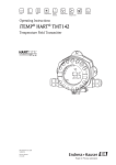
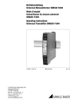
Das Gerät kann bei Verwendung stabiler Sensoren direkt auf den Sensor montiert werden. Für
die abgesetzte Montage an einem Rohr steht ein Montagehalter zur Verfügung.
a0007952
Abb. 1: Direkte Wand- oder Rohrmontage
2.2
Montagebedingungen
2.2.1 Abmessungen
• Aluminium- oder Edelstahlgehäuse: 132 (5.2") x 135 (5.3") x 106 (4.2") mm (BxHxT)
2.2.2 Montageort
• Umgebungstemperatur
– mit Anzeige -40 bis +80 °C (-40 bis 176 °F)
– ohne Anzeige -40 bis 85 °C (-40 bis 185 °F)
Für den Einsatz im Ex-Bereich siehe Installationsvorschriften in der Ex-Dokumentation.
!
Hinweis!
Bei Temperaturen < -20 °C (-4 °F) kann die Anzeige träge reagieren. Bei Temperaturen
< -30 °C (-22 °F) ist die Ablesbarkeit der Anzeige nicht mehr gewährleistet!
• Klimaklasse C nach EN 60654-1
• Schutzart IP 67, NEMA 4x bei korrekter Verdrahtung (→ Kap. 3.4)
6
Endress+Hauser
TMT142 HART®
2.3
Montage
Montage
2.3.1 Direkte Wandmontage
Zur direkten Wandmontage des Gerätes gehen Sie wie folgt vor:
• 2 Löcher bohren. Bohrschablone und Bohrabstand s. Abb. 1.
• Gerät an der Wand mit 2 Schrauben (M6) anbringen.
2.3.2 Rohrmontage
Der Montagehalter ist geeignet für Rohre mit einem Durchmesser zwischen 1,5" - 3,3". Zur
Montage des Gerätes an ein Rohr gehen Sie wie folgt vor → Abb. 1:
• Den Montagehalter an das Rohr anbringen.
• Bei Rohren mit einem Durchmesser von 1,5" bis 2,2" muss die zusätzliche Montageplatte verwendet werden.
• Gerät am Montagehalter mit den mitgelieferten Schrauben anbringen. Für Rohre mit einem
Durchmesser von 2,2" - 3,3" ist die Montageplatte nicht notwendig.
2.4
Montagekontrolle
Führen Sie nach der Montage des Gerätes folgende Kontrollen durch:
Gerätezustand und -spezifikationen
Ist das Gerät beschädigt (Sichtkontrolle)?
Entspricht das Gerät den Messstellenspezifikationen, wie
Umgebungstemperatur, usw.?
Endress+Hauser
Hinweise
→ Kap. 2.2
7
Verdrahtung
3
"
TMT142 HART®
Verdrahtung
Achtung!
• Gerät nicht unter Betriebsspannung installieren bzw. verdrahten. Ein Nichtbeachten kann zur
Zerstörung von Teilen der Elektronik führen.
• Beachten Sie für den Anschluss von Ex-zertifizierten Geräten die entsprechenden Hinweise
und Anschlussbilder in den spezifischen Ex-Zusatzdokumentationen zu dieser Betriebsanleitung. Bei Fragen steht Ihnen Ihre E+H-Vertretung gerne zur Verfügung.
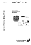
a0007959
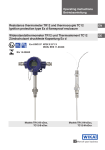
Abb. 2: Öffnen des Feldtransmitters
Gehen Sie bei der Verdrahtung des Gerätes grundsätzlich wie folgt vor:
8
1.
Entfernen Sie die Deckelkralle (Pos. 1).
2.
Schrauben Sie den Gehäusedeckel am Anschlussraum zusammen mit dem O-Ring ab
(Pos. 2).
3.
Ziehen Sie gegebenenfalls das Display mit der Verdrehsicherung von der Elektronikeinheit
ab (Pos. 3).
4.
Öffnen Sie die 2 Schrauben der Elektronikeinheit und entnehmen Sie die Elektronikeinheit
(Pos. 4).
5.
Öffnen Sie die Kabelverschraubungen (Pos. 5) am Gerät.
6.
Führen Sie die Leitungen durch die Öffnung der Kabelverschraubungen.
7.
Schliessen Sie die Leitungen gemäß Abb. 3 am Klemmenblock an.
Endress+Hauser
TMT142 HART®
Verdrahtung
8.
Nach erfolgter Verdrahtung drehen Sie die Schraubklemmen der Anschlüsse fest. Ziehen
Sie die Kabelverschraubungen (Pos. 5) wieder an. Beachten Sie dabei auch Kap. 3.4.
9.
Schrauben Sie die Elektronikeinheit (Pos. 4) an, stecken gegebenenfalls das Display mit
Verdrehsicherung (Pos. 3) auf und schrauben den Gehäusedeckel mit O-Ring (Pos. 2) wieder fest. Zum Abschluss bringen Sie die Deckelkralle (Pos. 1) wieder an.
Um Anschlussfehler zu vermeiden, beachten Sie in jedem Falle vor der Inbetriebnahme die Hinweise in der Anschlusskontrolle!
!
Hinweis!
Das Display mit Halterung kann jeweils in 90°-Schritten in die von Ihnen gewünschte Position
auf das Elektronikmodul am jeweiligen Steckplatz gesteckt werden. Im gesteckten Zustand ist
das Drehen des Displays nicht möglich.
3.1
Verdrahtung auf einen Blick
3.1.1 Klemmenbelegung
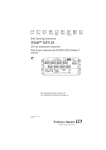
T09-TMT142ZZ-04-00-XX-de-003
Abb. 3: Verdrahtung des Feldtransmitters - Klemmenbelegung
ESD - Electrostatic discharge
Schützen Sie die Klemmen vor elektrostatischer Entladung. Ein Nichtbeachten kann zur Zerstörung von Teilen der Elektronik führen.
3.2
"
Anschluss Messeinheit
Achtung!
Ist das Gerät nicht durch die Montage des Gehäuses geerdet, wird eine Erdung über eine der
Erdungsschrauben empfohlen.
Endress+Hauser
9
Verdrahtung
TMT142 HART®
3.2.1 Anschluss HART®
!
Hinweis!
Ist der HART® -Kommunikationswiderstand nicht im Speisegerät eingebaut, muss notwendigerweise ein Kommunikationswiderstand von 250 Ω in die 2-Draht-Leitung eingebaut werden.
Beachten Sie für den Anschluss auch die von der HART® Communication Foundation herausgegebenen Dokumentationen, speziell HCF LIT 20: “HART, eine technische Übersicht”.
Anschlussmöglichkeit mit E+H Speisegerät RN221N
T09-TMT142ZZ-04-00-XX-xx-001
Abb. 4: HART®-Anschluss mit E+H Speisegerät RN 221N
Anschlussmöglichkeit mit anderen Speisegeräten
T09-TMT142ZZ-04-00-XX-xx-002
Abb. 5: HART®-Anschluss mit anderen Speisegeräten
10
Endress+Hauser
TMT142 HART®
3.3
Verdrahtung
Schirmung und Potenzialausgleich
Bei der Installation ist zu beachten:
Werden geschirmte Leitungen verwendet, muss die Schirmung der Ausgangsseite (Ausgangssignal 4 bis 20 mA) und die Schirmung der Sensoranschlussseite das gleiche Potenzial haben!
In Anlagen mit starken elektromagnetischen Feldern wird eine Schirmung aller Leitungen mit
niederohmiger Anbindung an Erde empfohlen. Bei Sensorleitungen außerhalb Gebäuden wird
wegen der Gefahr von Blitzeinschlag eine Schirmung empfohlen!
3.4
Schutzart
Das Gerät erfüllt alle Anforderungen gemäß Schutzart IP 67. Um nach erfolgter Montage im Feld
oder nach einem Servicefall die Schutzart IP 67 zu gewährleisten, müssen folgende Punkte
zwingend beachtet werden:
• Die Gehäusedichtungen müssen sauber und unverletzt in die Dichtungsnut eingelegt werden.
Gegebenenfalls sind die Dichtungen zu trocknen, zu reinigen oder zu ersetzen.
• Sämtliche Gehäuseschrauben und Schraubdeckel müssen fest angezogen sein.
• Die für den Anschluss verwendeten Kabel müssen den spezifizierten Außendurchmesser aufweisen (z.B. M20 x 1,5, Kabeldurchmesser 8 bis 12 mm).
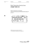
• Kabeleinführung fest anziehen (→ Abb. 6).
• Kabel vor der Kabeleinführung in einer Schlaufe verlegen ("Wassersack", → Abb. 6). Auftretende Feuchtigkeit kann so nicht zur Einführung gelangen. Montieren Sie das Gerät möglichst so, dass die Kabeleinführungen nicht nach oben gerichtet sind.
• Nicht benutzte Kabeleinführungen sind durch einen Blindstopfen (im Lieferumfang enthalten) zu ersetzen.
• Die verwendete Schutztülle darf nicht aus der Kabeleinführung entfernt werden.
F06-xxxxxxxx-04-xx-xx-xx-005
Abb. 6: Anschlusshinweise zur Einhaltung der Schutzart IP 67
Endress+Hauser
11
Verdrahtung
3.5
TMT142 HART®
Anschlusskontrolle
Führen Sie nach der elektrischen Installation des Gerätes folgende Kontrollen durch:
12
Gerätezustand und -spezifikationen
Hinweise
Sind Gerät oder Kabel beschädigt (Sichtkontrolle)?
-
Elektrischer Anschluss
Hinweise
Ist die Kabeltypenführung einwandfrei getrennt - Ohne Schleifen
und Überkreuzungen?
-
Sind die montierten Kabel von Zug entlastet?
-
Ist die Klemmenbelegung richtig? Vergleichen Sie das Anschlussschema vom Klemmenblock oder → Abb. 3.
siehe Anschlussschema am
Gehäuse
Sind alle Schrauben der Anschlussklemmen festgedreht?
Ist die Kabelverschraubung dicht?
Ist der Gehäusedeckel zugeschraubt?
Sichtkontrolle
Endress+Hauser
TMT142 HART®
Inbetriebnahme
4
Inbetriebnahme
4.1
Installations- und Funktionskontrolle
Vor der ersten Inbetriebnahme vergewissern Sie sich bitte, dass:
• das Gerät korrekt montiert wurde und
• der elektrische Anschluss richtig ist.
4.2
Einschalten des Gerätes
Falls Sie die Abschlusskontrollen durchgeführt haben, schalten Sie nun die Versorgungsspannung ein. Das Gerät ist nach ca. 18 Sekunden betriebsbereit! Nach erfolgreichem Einschaltvorgang wird der normale Messbetrieb aufgenommen. Auf der Anzeige erscheint ein Messwert
und/oder eine Statusmeldung.
4.3
Anzeige- und Bedienelemente
4.3.1 Anzeigedarstellung
40
30
20
10
0
50
!
60
70
K °F °C %
80
90
100
Ê
Ë
Ì
Í
Î
Ï
Ð
T09-TMT142ZZ-07-00-00-xx-001
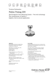
Abb. 7: LC-Anzeige des Feldtransmitters (beleuchtet, steckbar in 90°-Schritten)
Endress+Hauser
13
Inbetriebnahme
TMT142 HART®
Anzeigesymbole
Pos.nr.
Funktion
Beschreibung
1
Bargraphanzeige
In 10%-Schritten mit Marken für Messbereichsunter-/überschreitung. Die Bargraphanzeige blinkt bei Auftreten eines
Fehlers.
2
Anzeige ’Achtung’
Diese Anzeige erscheint bei Fehler oder Warnung
3
Einheitenanzeige K, °F, °C, %
Einheitenanzeige für den jeweilig angezeigten Messwert
4
Messwertanzeige (Ziffernhöhe
20,5 mm)
Anzeige des Messwerts. Bei Warnung wird zwischen Messwert und dem Code der Warnung gewechselt. Bei Fehler
wird statt dem Messwert der Fehlercode angezeigt.
5
Status- und Infoanzeige
Anzeige, welcher Wert gerade aktuell auf dem Display
erscheint. Bei PV kann ein kundenspezifischer Text eingegeben werden. Bei Warnung wird gleichzeitig mit dem Code
für die Warnung ’WARN’ angezeigt. Bei Fehler wird
’ALARM’ angezeigt.
6
Anzeige ’Kommunikation’
Bei Lese- und Schreibzugriff über das HART® -Protokoll
erscheint das Kommunikationssymbol
7
Anzeige ’Konfiguration gesperrt’
Bei Sperrung der Parametrierung/Konfiguration über Softoder Hardware erscheint das Symbol ’Konfiguration gesperrt’
4.3.2 Vor-Ort-Bedienung, Hardware-Einstellungen
T09-TMT162ZZ-19-00-00-xx-001
Abb. 8: Hardwareeinstellungen über Jumper J1, J2 und J3
14
Endress+Hauser
TMT142 HART®
Inbetriebnahme
ESD - Electrostatic discharge
Schützen Sie die Klemmen vor elektrostatischer Entladung. Ein Nichtbeachten kann zur Zerstörung von Teilen der Elektronik führen.
Die Jumper J1, J2 und J3 für die Hardwareeinstellung befinden sich auf dem Elektronikmodul.
Für die Einstellung der Jumper schrauben Sie den Gehäusedeckel ab (→ Abb. 2) und ziehen Sie
gegebenenfalls das Display ab .
Sperren der Parametrierung bzw. Konfiguration über Hardware mit Jumper J1
TRANSMITTER SECURITY
ON
Parametrierung/Konfiguration gesperrt
OFF
Freigabe Parametrierung/Konfiguration
Die Sperrung der Parametrierung/Konfiguration über Hardwareeinstellung hat Priorität gegenüber der Softwareeinstellung.
Einstellung des Fehlerverhaltens über Hardware mit Jumper J2
FAILURE MODE
LO
≤ 3,6 mA
HI
≥ 21,0 mA
Das über die Jumper eingestellte Fehlerverhalten wird nur bei Ausfall des Mikrocontrollers wirksam.
!
Hinweis!
Bitte überprüfen Sie die Übereinstimmung der Einstellung des Fehlerverhaltens über Hardware
und Software.
Einstellung der Hardware mit Jumper J3 (nur für Geräte ohne Display)
Mit dem gesteckten Jumper J3 kann die minimale Betriebsspannung von 11 V auf 8 V reduziert
werden.
Endress+Hauser
15
TMT142 HART®
Table of contents
1
Safety instructions . . . . . . . . . . . . . . . . . . . . . . . . . . . . . . . . . . . . . . . . . . . 18
1.1
1.2
1.3
1.4
1.5
Designated use . . . . . . . . . . . . . . . . . . . . . . . . . . . . . . . . . . . . . . . . . . . . . . . . . . . . . . . . . . . . . . . . . .
Installation, commissioning and operation . . . . . . . . . . . . . . . . . . . . . . . . . . . . . . . . . . . . . . . . . . . . . .
Operational safety . . . . . . . . . . . . . . . . . . . . . . . . . . . . . . . . . . . . . . . . . . . . . . . . . . . . . . . . . . . . . . . .
Return . . . . . . . . . . . . . . . . . . . . . . . . . . . . . . . . . . . . . . . . . . . . . . . . . . . . . . . . . . . . . . . . . . . . . . . . .
Notes on safety conventions and icons . . . . . . . . . . . . . . . . . . . . . . . . . . . . . . . . . . . . . . . . . . . . . . . . .
2
Installation instructions . . . . . . . . . . . . . . . . . . . . . . . . . . . . . . . . . . . . . . . 20
2.1
2.2
2.3
2.4
Quick installation guide . . . . . . . . . . . . . . . . . . . . . . . . . . . . . . . . . . . . . . . . . . . . . . . . . . . . . . . . . . . .
Installation conditions . . . . . . . . . . . . . . . . . . . . . . . . . . . . . . . . . . . . . . . . . . . . . . . . . . . . . . . . . . . . .
Installation instructions . . . . . . . . . . . . . . . . . . . . . . . . . . . . . . . . . . . . . . . . . . . . . . . . . . . . . . . . . . . .
Post-installation check . . . . . . . . . . . . . . . . . . . . . . . . . . . . . . . . . . . . . . . . . . . . . . . . . . . . . . . . . . . . .
3
Wiring. . . . . . . . . . . . . . . . . . . . . . . . . . . . . . . . . . . . . . . . . . . . . . . . . . . . . 22
3.1
3.2
3.3
3.4
3.5
3.6
Quick wiring guide . . . . . . . . . . . . . . . . . . . . . . . . . . . . . . . . . . . . . . . . . . . . . . . . . . . . . . . . . . . . . . .
Connecting the sensor . . . . . . . . . . . . . . . . . . . . . . . . . . . . . . . . . . . . . . . . . . . . . . . . . . . . . . . . . . . . .
Connecting the device . . . . . . . . . . . . . . . . . . . . . . . . . . . . . . . . . . . . . . . . . . . . . . . . . . . . . . . . . . . .
Shielding and potential equalization . . . . . . . . . . . . . . . . . . . . . . . . . . . . . . . . . . . . . . . . . . . . . . . . . . .
Degree of protection . . . . . . . . . . . . . . . . . . . . . . . . . . . . . . . . . . . . . . . . . . . . . . . . . . . . . . . . . . . . . .
Connection check . . . . . . . . . . . . . . . . . . . . . . . . . . . . . . . . . . . . . . . . . . . . . . . . . . . . . . . . . . . . . . . .
4
Commissioning. . . . . . . . . . . . . . . . . . . . . . . . . . . . . . . . . . . . . . . . . . . . . . 28
4.1
4.2
4.3
Function check . . . . . . . . . . . . . . . . . . . . . . . . . . . . . . . . . . . . . . . . . . . . . . . . . . . . . . . . . . . . . . . . . . 28
Switching on the device . . . . . . . . . . . . . . . . . . . . . . . . . . . . . . . . . . . . . . . . . . . . . . . . . . . . . . . . . . . 28
Display and operating elements . . . . . . . . . . . . . . . . . . . . . . . . . . . . . . . . . . . . . . . . . . . . . . . . . . . . . . 28
18
18
18
19
19
20
20
21
21
23
23
24
26
26
27
These are Brief Operating Instructions.
Please refer to the Operating Instructions and the other documentation on the CD-ROM provided for
more detailed information.
These Brief Operating Instructions are not intended as a substitute for the Operating Instructions.
The complete device documentation comprises:
• These Brief Operating Instructions
• A CD-ROM with:
– The Operating Instructions
– Approvals and safety certificates
– Other device-specific information.
Endress+Hauser
17
Safety instructions
1
#
TMT142 HART®
Safety instructions
Warning!
Electric shocks can cause death or serious injury.
Proceed with extreme caution when working with cables and terminals. If the
device/measuring system is installed in a high-voltage environment and a malfunction or
installation error occurs, high voltage can be present at the terminals or the device/measuring
system itself.
1.1
Designated use
• The device is a universal and configurable temperature field transmitter with one temperature
sensor input for resistance thermometers (RTD), thermocouples (TC) and resistance and
voltage transmitters. The unit is designed for mounting in the field.
• Using the device for any purpose other than that described jeopardizes people's safety, and the
safety of the entire measuring system, and is therefore not permitted.
• The manufacturer does not accept liability for damage caused by improper or non-designated
use.
1.2
Installation, commissioning and operation
Note the following points:
• The device may only be installed, connected, commissioned and maintained by properly
qualified and authorized staff (e.g. electrical technicians) in strict compliance with these
Operating Instructions, applicable standards, legal regulations and certificates (depending on
the application).
• The specialist staff must have read and understood these Operating Instructions and must
follow the instructions they contain. If any areas are unclear in the Brief Operating
Instructions, you must read the Operating Instructions (on the CD-ROM) which contain
detailed information on the measuring system.
• The device may only be modified or repaired if expressly permitted in the Operating
Instructions (CD-ROM).
• Damaged devices may not be put into operation and must be marked as defective.
1.3
Operational safety
• The device is safely built and tested according to state-of-the-art technology and has left the
factory in perfect condition as regards technical safety. The applicable regulations and
European standards have been taken into account.
• Please pay particular attention to the technical data on the nameplate! The nameplate is on
the side of the housing.
Hazardous areas
Devices for use in hazardous areas are marked accordingly on the nameplate. When using in
hazardous areas, the national safety requirements must be met. Separate Ex documentation,
which is an integral part of these Operating Instructions, is supplied with the device. Compliance
with the installation instructions, ratings and safety instructions as listed in this supplementary
18
Endress+Hauser
TMT142 HART®
Safety instructions
documentation is mandatory. The documentation number of this document (XA) is also
indicated on the nameplate.
Electromagnetic compatibility
The measuring system complies with the general safety requirements in accordance with
EN 61010 and the EMC requirements of IEC/EN 61326 and NAMUR Recommendations
NE 21, NE 43 and NE 89.
#
Warning!
Power must be supplied to the device from a 11 to 40 VDC power supply in accordance with
NEC Class 02 (low voltage/current) with short-circuit power limitation to 8 A/150 VA.
1.4
Return
Follow the instructions on returning the device as outlined in the Operating Instructions on the
CD-ROM provided.
1.5
Notes on safety conventions and icons
Safety instructions in these Brief Operating Instructions are indicated using the following safety
conventions and icons:
"
Caution!
This symbol draws attention to activities or procedures that can lead to defective operation or to
destruction of the device if not carried out properly.
#
Warning!
This symbol draws attention to activities or procedures that can lead to injuries to persons, safety
risks or the destruction of the device if not carried out properly.
!
Note!
This symbol draws attention to activities or procedures that have an indirect effect on operation,
or can trigger an unforeseen device reaction if not carried out properly.
ESD – Electrostatic discharge
Protect the terminals against electrostatic discharge. Failure to comply with this instruction can
result in the destruction of parts of the electronics.
Endress+Hauser
19
Installation instructions
2
Installation instructions
2.1
Quick installation guide
TMT142 HART®
If stable sensors are used, the device can be fitted directly to the sensor. For remote mounting
to a stand pipe, a mounting kit is available.
a0007952
Fig. 1: Direct wall or pipe mounting
2.2
Installation conditions
2.2.1 Dimensions
• Aluminum or stainless steel housing: 132 (5.2") x 135 (5.3") x 106 (4.2") mm (BxHxD)
2.2.2 Installation point
• Ambient temperature
– With display: -40 to +80 °C (-40 °F to +176 °F)
– Without display: -40 to +85 °C (-40 °F to +185 °F)
For use in hazardous areas, see Ex certificate
!
Note!
The display can react slowly for temperatures < -20 °C (< -4 °F). Readability of the display
cannot be guaranteed at temperatures < -30 °C (-22 °F).
• Climate class C to EN 60654-1
• Degree of protection IP 67, NEMA 4x if wired correctly (→ Chap. 3.4)
20
Endress+Hauser
TMT142 HART®
2.3
Installation instructions
Installation instructions
2.3.1 Direct wall mounting
Proceed as follows to mount the device directly on wall:
• Drill 2 holes. Drill template and drill hole distance → Fig. 1.
• Attach the device to the wall with 2 screws (M6).
2.3.2 Pipe installation
The mounting bracket is suited for pipes with a diameter between 1.5" - 3.3". Proceed as follows
to mount the device on a pipe (→ Fig. 1):
• Attach the mounting bracket to the pipe.
• The additional mounting plate must be used for pipes with a diameter of 1.5" to 2.2".
• Fix the device to the mounting bracket with the two screws supplied. The mounting plate is
not needed for pipes with a diameter of 2.2" - 3.3".
2.4
Post-installation check
After installing the device, always run the following final checks:
Device condition and specifications
Notes
Is the device visibly damaged (visual check)?
-
Does the device comply to the measurement point
specifications, such as ambient temperature, etc.?
→ Chap. 2.2
Endress+Hauser
21
Wiring
TMT142 HART®
3
"
Wiring
Caution!
• Switch off power supply before installing or connecting the device. Failure to comply with this
instruction can result in the destruction of parts of the electronics.
• When installing Ex-approved devices in a hazardous area please take special note of the
instructions and connection schematics in the respective Ex documentation added to these
Operating Instructions. The local E+H representative is available for assistance if required.
a0007959
Fig. 2: Opening the field transmitter
For wiring the device proceed as follows:
1.
22
Remove the cover clamp (item 1).
2.
Remove the device cover together with the O-ring (item 2).
3.
Remove display with twist protection if applicable from the electronics module (item 3).
4.
Open the 2 screws of the electronics module and remove the electronics module (item 4).
5.
Open the cable gland at the device (item 5).
6.
Feed the cable through the opening in the cable gland.
7.
Connect the wires to the terminal block as per (→ Fig. 3).
8.
Make sure that the terminal screws are tight. Re-seal the cable gland by screwing the cover
back on. In doing so, also pay particular attention to → Chap. 3.4.
Endress+Hauser
TMT142 HART®
9.
Wiring
On completion of the wiring, screw on the electronics module (item 4) again, plug on the
display with twist protection (item 3) again if applicable and screw the housing cover
together with the O-ring (item 2) down again. Finally refit the cover clamp (item 1).
In order to avoid connection errors always take note of the hints given in the section
connection check!
!
Note!
It is possible to adjust the display with retainer in 90°stages to your desired position and
rearrange it on the particular slot in the electronics module. It is not possible to rotate the display
when the display is plugged on already.
3.1
Quick wiring guide
3.1.1 Terminal assignment
T09-TMT142ZZ-04-00-XX-en-003
Fig. 3: Wiring the field transmitter - terminal assignment
ESD – Electrostatic discharge
Protect the terminals against electrostatic discharge. Failure to comply with this instruction can
result in the destruction of parts of the electronics.
3.2
"
Connecting the device
Caution!
• Switch off power supply before installing or connecting the device. Failure to observe this may
result in destruction of parts of the electronics.
• If the device has not been grounded as a result of the housing being installed, we
recommended grounding it via one of the ground screws.
Endress+Hauser
23
Wiring
TMT142 HART®
3.2.1 HART® connection
!
Note!
If the HART® communication resistance is not built into the power supply, a 250 Ω
communication resistor must be fitted into the 2-wire supply lines.
For connection hints, please take special notice of the documentation supplied by the HART®
Communication Foundation, specifically HCF LIT 20: “HART, a technical overview”.
Connection using the Endress+Hauser power supply RN221N
T09-TMT142ZZ-04-00-XX-xx-001
Fig. 4: HART® connection with the Endress+Hauser power supply RN221N
Connection using other power supplies
T09-TMT142ZZ-04-00-XX-xx-002
Fig. 5: HART® connection using other power supplies
24
Endress+Hauser
TMT142 HART®
3.3
Wiring
Shielding and potential equalization
Please take note when installing the device:
If screened (shielded) cables are used then the shielding connected to the output (output signal
4 to 20 mA) must be at the same potential as the shielding at the sensor connection!
When operating in plants with high electromagnetic fields, it is recommended that all cables be
shielded using a low ohm ground connection. Due to the possible danger of lightning strikes,
shielding is also recommended for cables that are run outside buildings!
3.4
Degree of protection
The device conforms to the requirements to IP 67 ingress protection. In order to fulfill an IP 67
degree of protection after installation or service, the following points must be taken into
consideration:
• The housing seals must be clean and undamaged when inserted into their grooves. The seals
must be dried, cleaned or replaced if necessary.
• All housing screws and screw caps must be firmly tightened.
• The cables used for connection must be of the correct specified outside diameter (e.g. M20 x
1.5, cable diameter from 8 to 12 mm; 0.315 to 0.47 in).
• Firmly tighten the cable gland (Fig. 6).
• The cables must loop down before they enter the cable glands (“water trap”, Fig. 6). This
means that any moisture that may form cannot enter the gland. Install the device so that the
cable glands are not facing upwards.
• Cable glands not used are to be blanked off using the dummy plugs provided.
• Do not remove the grommet from the cable gland.
F06-xxxxxxxx-04-xx-xx-xx-005
Fig. 6: Connection hints to retain IP 67 protection
Endress+Hauser
25
Wiring
TMT142 HART®
3.5
Connection check
After the electrical installation of the device, always perform the following final checks:
26
Device condition and specification
Hint
Are the device or the cables damaged (visual check)?
-
Electrical connection
Hint
Is the cable/conduit installation correctly separated, with no loops or
crossovers?
-
Are the cables’ load relieved?
-
Have the cables been correctly connected? Compare with the
connection schematic on the terminals or see Fig. 3.
See connection schematic
on the housing
Are all terminal screws tightened?
Is the cable or conduit entry sealed?
Is the housing cover screwed tight?
Visual check
Endress+Hauser
TMT142 HART®
Commissioning
4
Commissioning
4.1
Function check
Prior to commissioning, please ensure that:
• The device has been mounted correctly and
• the electrical connection is correct.
4.2
Switching on the device
Once the final checks have been successfully completed, it is time to switch on the supply
voltage. The device is ready for operation after approx. 18 seconds!
Normal measuring mode commences as soon as the switch-on procedure is completed. A
measuring value and/or a status variable appear on the display.
4.3
Display and operating elements
4.3.1 Display
40
30
20
10
50
60
!
70
K °F °C %
0
80
90
100
Ê
Ë
Ì
Í
Î
Ï
Ð
T09-TMT142ZZ-07-00-00-xx-001
Fig. 7: LC display of the field transmitter (illuminated, can be plugged in in 90° steps)
Display symbols
Pos.
no.
Function
Description
1
Bargraph display
In 10% steps with overrange and underrange marks.
The bargraph display flashes when an error occurs.
2
Display ’Warning’
This display mode appears when an error occurs or a
warning is given.
3
Engineering unit display K, °F, °C or %
Engineering unit for the measured value being
displayed.
Endress+Hauser
27
Commissioning
TMT142 HART®
Pos.
no.
Function
Description
4
Measured value display
(0.81" / 20.5 mm character size)
Measured value display. If a warning is present this
display alternates between the measured value and the
warning code. In the event of an error, the error code
is dispalyed instead of the measured value.
5
Status and information display
Display of which value is being indicated on the
display. On PV a customer specific text can be entered.
On warning, the display shows the warning code as
well as "WARN". On faults the display shows
"ALARM".
6
Display "Communication"
The communication icon appears on read or write
access using the HART® protocol.
7
Display "Configuration locked"
If the software or hardware setup/configuration is
locked, the "Configuration locked" icon appears.
4.3.2 Local operation, setup of the hardware
T09-TMT162ZZ-19-00-00-xx-001
Fig. 8: Hardware setup using jumpers J1, J2 and J3
ESD – Electrostatic discharge
Protect the terminals from electrostatic discharge. Failure to observe this may result in
destruction of parts of the electronics.
Jumpers J1, J2 and J3 for the hardware setup can be found on the electronics module. In order
to set the jumper, open the device cover and if applicable pull off the display.
28
Endress+Hauser
TMT142 HART®
Commissioning
Setup or configuration hardware lock using jumper J1
TRANSMITTER SECURITY
ON
Setup/configuration locked
OFF
Setup/configuration unlocked
The hardware setup/configuration lock has priority over the software setup.
Setup hardware fault conditioning using jumper J2
FAILURE MODE
LO
≤ 3.6 mA
HI
≥ 21.0 mA
The failure mode conditioning setup using the jumper is only active when the microcontroller
fails.
!
Note!
Please check that the hardware and software failure mode conditioning correspond with each
other.
Hardware setup using jumper J3 (only for units without display)
Using jumper 3 the minimum operating voltage can be reduced from 11 V to 8 V.
Endress+Hauser
29
TMT142 HART®
Sommaire
1
Conseils de sécurité . . . . . . . . . . . . . . . . . . . . . . . . . . . . . . . . . . . . . . . . . . 32
1.1
1.2
1.3
1.4
1.5
Utilisation conforme . . . . . . . . . . . . . . . . . . . . . . . . . . . . . . . . . . . . . . . . . . . . . . . . . . . . . . . . . . . . . .
Montage, mise en service, exploitation . . . . . . . . . . . . . . . . . . . . . . . . . . . . . . . . . . . . . . . . . . . . . . . .
Sécurité de fonctionnement . . . . . . . . . . . . . . . . . . . . . . . . . . . . . . . . . . . . . . . . . . . . . . . . . . . . . . . .
Retour de matériel . . . . . . . . . . . . . . . . . . . . . . . . . . . . . . . . . . . . . . . . . . . . . . . . . . . . . . . . . . . . . . .
Symboles de sécurité utilisés . . . . . . . . . . . . . . . . . . . . . . . . . . . . . . . . . . . . . . . . . . . . . . . . . . . . . . . .
2
Montage . . . . . . . . . . . . . . . . . . . . . . . . . . . . . . . . . . . . . . . . . . . . . . . . . . . 34
2.1
2.2
2.3
2.4
Montage en bref . . . . . . . . . . . . . . . . . . . . . . . . . . . . . . . . . . . . . . . . . . . . . . . . . . . . . . . . . . . . . . . . .
Conditions de montage. . . . . . . . . . . . . . . . . . . . . . . . . . . . . . . . . . . . . . . . . . . . . . . . . . . . . . . . . . . .
Montage . . . . . . . . . . . . . . . . . . . . . . . . . . . . . . . . . . . . . . . . . . . . . . . . . . . . . . . . . . . . . . . . . . . . . .
Contrôle du montage . . . . . . . . . . . . . . . . . . . . . . . . . . . . . . . . . . . . . . . . . . . . . . . . . . . . . . . . . . . . .
3
Raccordement . . . . . . . . . . . . . . . . . . . . . . . . . . . . . . . . . . . . . . . . . . . . . . 36
3.1
3.2
3.3
3.4
3.5
Câblage en bref . . . . . . . . . . . . . . . . . . . . . . . . . . . . . . . . . . . . . . . . . . . . . . . . . . . . . . . . . . . . . . . . .
Raccordement unité de mesure . . . . . . . . . . . . . . . . . . . . . . . . . . . . . . . . . . . . . . . . . . . . . . . . . . . . .
Blindage et compensation de potentiel . . . . . . . . . . . . . . . . . . . . . . . . . . . . . . . . . . . . . . . . . . . . . . . .
Protection . . . . . . . . . . . . . . . . . . . . . . . . . . . . . . . . . . . . . . . . . . . . . . . . . . . . . . . . . . . . . . . . . . . . .
Contrôle du raccordement . . . . . . . . . . . . . . . . . . . . . . . . . . . . . . . . . . . . . . . . . . . . . . . . . . . . . . . . .
32
32
32
33
33
34
34
35
35
37
37
39
39
40
4
Mise en service . . . . . . . . . . . . . . . . . . . . . . . . . . . . . . . . . . . . . . . . . . . . . 41
4.1
4.2
4.3
Contrôle de l’installation et du fonctionnement . . . . . . . . . . . . . . . . . . . . . . . . . . . . . . . . . . . . . . . . . . 41
Mise sous tension de l’appareil de mesure . . . . . . . . . . . . . . . . . . . . . . . . . . . . . . . . . . . . . . . . . . . . . . 41
Eléments d’affichage et de commande. . . . . . . . . . . . . . . . . . . . . . . . . . . . . . . . . . . . . . . . . . . . . . . . . 41
Les présentes instructions sont condensées.
Des informations plus détaillées figurent dans le manuel de mise en service et dans les autres documentations sur le CD-ROM fourni.
Les présentes instructions condensées ne remplacent pas le manuel de mise en service.
La documentation complète de l'appareil comprend :
• les présentes instructions condensées
• un CD-ROM avec :
– le manuel de mise en service
– les agréments et certificats de sécurité
– d'autres informations spécifiques à l'appareil.
31
Sommaire
1
#
TMT142 HART®
Conseils de sécurité
Danger!
Les décharges électriques peuvent entrainer la mort ou de graves dommages corporels.
Procéder avec une extrême prudence lorsque vous touchez des câbles et bornes. Si l'appareil/l'ensemble de mesure est installé dans environnement sous haute tension et si l'on observe
un défaut ou une erreur d'installation, il se peut que les bornes de raccordement ou l'appareil/l'installation soient sous haute tension.
1.1
Utilisation conforme
• L'appareil est un transmetteur de température de terrain, universel et configurable, pour thermorésistances (RTD), thermocouples (TC), résistances et tensions. Il a été conçu pour un
montage terrain.
• Une utilisation autre que celle décrite compromet la sécurité des personnes et de toute l'installation de mesure et n'est de ce fait pas admissible.
• Le fabricant ne couvre pas les dommages résultant d'une utilisation non conforme à l'objet.
1.2
Montage, mise en service, exploitation
Respectez les points suivants :
• L'appareil ne doit être monté, raccordé, mis en service et entretenu que par un personnel qualifié et autorisé (par ex. électricien) qui respectera les présentes instructions, les normes en
vigueur, les directives légales et les certificats (selon l'application).
• Le personnel spécialisé doit impérativement avoir lu, compris et suivi les présentes instructions. En cas de problèmes de compréhension de ces instructions, il convient de se référer au
manuel de mise en service (sur CD-ROM). Vous y trouverez toutes les informations détaillées
relatives au système de mesure.
• Les modifications et réparations de l'appareil ne doivent être effectuées que si le manuel de
mise en service (CD-ROM) les autorise expressément.
• Les appareils défectueux ne doivent pas être mis en service et être marqués comme tels.
1.3
Sécurité de fonctionnement
• L'appareil a été construit et contrôlé dans les règles de l'art. Il a quitté nos établissements dans
un état technique parfait. Les directives et normes européennes en vigueur ont été respectées.
• Tenir compte des caractéristiques techniques sur la plaque signalétique ! La plaque signalétique se trouve sur le côté du boîtier.
Zone explosible
Les appareils destinés à une utilisation en zone explosible comportent la marque correspondante
sur la plaque signalétique. En cas d'utilisation en zones explosibles il convient de respecter les
normes nationales correspondantes. L'appareil est fourni avec une documentation Ex séparée,
partie intégrante du manuel complet. Les directives d'installation, valeurs de raccordement et
conseils de sécurité qui y figurent sont à respecter. Le numéro de cette documentation (XA)
figure également sur la plaque signalétique.
32
TMT142 HART®
Sommaire
Protection contre les parasites
L'ensemble de mesure satisfait aux exigences de sécurité selon EN 61010 et les exigences CEM
selon CEI/EN 61326 ainsi que les recommandations NAMUR NE 21, NE 43 et NE 89.
#
Danger!
L'appareil doit être alimenté par une tension de 11 à 40 VDC selon classe NEC 02 (basse tension/courant) avec une limitation de courant de coupure à 8 A/150 VA.
1.4
Retour de matériel
Tenir compte des conseils du manuel de mise en service sur le CD-ROM fourni.
1.5
Symboles de sécurité utilisés
Les conseils de sécurité donnés dans les présentes instructions condensées sont mis en évidence
à l'aide des symboles suivants :
"
Attention!
Ce symbole signale les actions ou procédures risquant d'entrainer des dysfonctionnements ou la
destruction de l'appareil si elles ne sont pas menées correctement.
#
Danger!
Ce symbole signale les actions ou procédures risquant d'entrainer des dommages corporels, un
risque pour la sécurité ou la destruction de l'appareil si elles ne sont pas menées correctement.
!
Remarque!
Ce symbole signale les actions ou procédures susceptibles de perturber indirectement le fonctionnement des appareils ou de générer des réactions imprévues si elles n'ont pas été menées
correctement.
ESD - Electrostatic discharge
Protéger les bornes contre les décharges électrostatiques. Un non respect peut entrainer la destruction de l'électronique.
33
Sommaire
TMT142 HART®
2
Montage
2.1
Montage en bref
Si les capteurs utilisés sont stables, le transmetteur peut y être directement associé. Un étrier de
fixation est disponible pour le montage sur colonne.
a0007952
fig. 1: Montage direct sur mur ou sur colonne
2.2
Conditions de montage
2.2.1 Dimensions
• Boitier aluminium ou inox : 132 (5.2") x 135 (5.3") x 106 (4.2") mm (LxHxP)
2.2.2 Lieu de montage
• Température ambiante
– avec affichage -40 à +80 °C (-40 à 176 °F)
– sans affichage -40 à 85 °C (-40 à 185 °F)
Pour les applications en zone Ex, voir les directives d'installation dans la documentation Ex.
!
Remarque!
Pour des températures < -20 °C (-4 °F) l'affichage peut être lent. Pour des températures
< -30 °C (-22 °F) la lisibilité de l'affichage n'est plus garantie !
• Classe climatique C selon EN 60654-1
• Protection IP 67, NEMA 4x en cas de câblage correct (→ chap. 3.4)
34
TMT142 HART®
2.3
Sommaire
Montage
2.3.1 Montage mural direct
Pour un montage mural direct de l'appareil, procéder comme suit :
• Percer 2 trous. Gabarit et écart des perçages v. fig. 1.
• Fixer l'appareil au mur à l'aide de 2 vis (M6).
2.3.2 Montage sur colonne
L'étrier de montage est conçu pour les colonnes avec un diamètre entre 1,5" - 3,3".
Pour le montage de l'appareil sur une colonne, procéder comme suit :→ fig. 1
• Fixer l'étrier sur la colonne
• Pour les colonnes d’un diamètre de 1,5" à 2,2" il faut utiliser en outre une plaque de montage.
• Fixer l'appareil sur l'étrier avec les vis livrées. Pour les colonnes d’un diamètre de 2,2" - 3,3"
la plaque de montage n'est pas nécessaire.
2.4
Contrôle du montage
Après le montage de l'appareil, procéder aux contrôles suivants :
Etat et spécifications de l'appareil
Remarques
L'appareil est-il endommagé (contrôle visuel)?
-
L'appareil correspond-il aux spécifications du point de mesure
comme la température ambiante etc ?
→ Chap. 2.2
35
Sommaire
3
"
TMT142 HART®
Raccordement
Attention!
• Ne pas installer ni câbler sous tension. Un non respect peut entrainer la destruction de l'électronique.
• Pour raccorder des appareils certifiés Ex, respectez les consignes et schémas contenus dans les
documentations Ex en supplément de ce manuel. Pour tout renseignement complémentaire,
contactez votre agence E+H.
a0007959
fig. 2: Ouverture du transmetteur de terrain
Pour le câblage de l'appareil procéder comme suit :
36
1.
Enlever le crampon du couvercle (Pos. 1).
2.
Dévisser le couvercle du boitier sur le compartiment de raccordement avec le joint torique
(Pos. 2).
3.
Retirer le cas échéant l'affichage avec la rotation sécurisée de l'électronique (pos. 3).
4.
Desserrer les deux vis de l'électronique et retirer l'électronique (pos. 4).
5.
Ouvrir les raccords de câble (pos. 5) sur l'appareil.
6.
Faire passer les câbles à travers l'ouverture des entrées.
7.
Relier les câbles au bornier conformément à fig. 3.
8.
Après le câblage serrer les bornes de raccordement. Serrer à nouveau les raccords de câble
(pos. 5).Tenir également compte du chap. 3.4.
TMT142 HART®
9.
Sommaire
Serrer l'électronique (pos. 4), embrocher le cas échéant l'affichage avec la rotation sécurisée (pos. 3) et visser à nouveau le couvercle du boitier avec le joint torique (pos. 2). Pour
finir, mettre à nouveau en place le crampon du couvercle (pos. 1).
Afin d'éviter les erreurs de raccordement, tenir compte dans tous les cas avant la mise en service
des conseils relatifs au contrôle du raccordement !
!
Remarque!
L'affichage avec le support peut être embroché dans la position souhaitée sur le module électronique par pas de 90°. Une fois embroché, l'affichage ne peut pas être tourné.
3.1
Câblage en bref
3.1.1 Occupation des bornes
T09-TMT142ZZ-04-00-XX-fr-003
fig. 3: Câblage du transmetteur de terrain - Occupation des bornes
ESD - Electrostatic discharge
Protéger les bornes contre les décharges électrostatiques. Un non respect peut entrainer la destruction de l'électronique.
3.2
"
Raccordement unité de mesure
Attention!
Si l'appareil n'est pas mis à la terre par le biais du boitier, il est recommandé de réaliser la mise
à la terre par le biais d'une des vis de terre.
37
Sommaire
TMT142 HART®
3.2.1 Raccordement HART®
!
Remarque!
Si la résistance de communication HART® n'est pas intégrée dans l'alimentation, il faut absolument intégrer une résistance de communication de 250 Ω dans le câble 2 fils.
Pour le raccordement, tenir également compte de la documentation éditée par HART® Communication Foundation, notamment la HCF LIT 20 : “HART, un aperçu technique”.
Possibilité de raccordement avec alimentation E+H RN221N
T09-TMT142ZZ-04-00-XX-xx-001
fig. 4: Raccordement HART®avec alimentation E+H RN 221N
Possibilités de raccordement avec d'autres alimentations
T09-TMT142ZZ-04-00-XX-xx-002
fig. 5: Raccordement HART®avec d'autres alimentations
38
TMT142 HART®
3.3
Sommaire
Blindage et compensation de potentiel
Lors de l'installation tenir compte des points suivants :
Si des câbles blindés sont utilisés, il faut que le blindage côté sortie (signal de sortie 4 à 20 mA)
et le blindage côté capteur aient le même potentiel !
Dans les installations avec des champs magnétiques puissants, il est recommandé de blinder tous
les câbles ayant une liaison à faible impédance avec la terre. Pour les câbles de capteur posés en
dehors de bâtiments, il est recommandé de prévoir un blindage en raison des risques de foudre !
3.4
Protection
L'appareil remplit toutes les exigences de la protection IP 67. Pour garantir la protection IP 67
après le montage sur le terrain ou la maintenance, il faut obligatoirement respecter les points suivants :
• Les joints du boîtier doivent être propres et en parfait état lorsqu'ils sont mis en place dans les
rainures de joint. Si nécessaire, les sécher, les nettoyer ou les remplacer.
• Il faut serrer fermement toutes les vis du boîtier et le couvercle à visser.
• Les câbles utilisés pour le raccordement doivent avoir le diamètre extérieur spécifié (par ex.
M20 x 1,5, diamètre de câble 8 à 12 mm).
• Serrer fermement l'entrée de câble.→ fig. 6
• Avant de passer dans l'entrée de câble, le câble doit faire une boucle vers le bas ("poche d'eau",
→ fig. 6) pour éviter l'humidité dans l'entrée de câble. Installer l'appareil de sorte que les
entrées de câble ne soient pas dirigées vers le haut.
• Les entrées de câble non utilisées doivent être remplacées par un bouchon aveugle (compris
dans la livraison).
• Ne pas retirer la gaine de protection de l'entrée de câble.
F06-xxxxxxxx-04-xx-xx-xx-005
fig. 6: Conseils de raccordement pour le respect de la protection IP 67
39
Sommaire
TMT142 HART®
3.5
Contrôle du raccordement
Après l'installation électrique du transmetteur, procéder aux contrôles suivants :
40
Etat et spécifications de l'appareil
Remarques
L'appareil ou le câble sont-ils endommagés (contrôle visuel) ?
-
Raccordement électrique
Remarques
Les types de câble sont-ils correctement séparés - sans boucles ni
croisements ?
-
Les câbles montés sont-ils munis d'une pince d'ancrage ?
-
L'occupation des bornes est-elle correcte ? Comparer le schéma
de raccordement du bornier ou → fig. 3.
Voir schéma de raccordement
sur le boitier
Toutes les vis des bornes de raccordement sont-elles bien
vissées ?
L'entrée de câble est-elle étanche ?
Le couvercle du boitier est-il vissé ?
Contrôle visuel
TMT142 HART®
Sommaire
4
Mise en service
4.1
Contrôle de l'installation et du fonctionnement
Avant la première mise en service, veuillez vérifier que :
• l'appareil a été monté correctement et
• le raccordement électrique est correct.
4.2
Mise sous tension de l'appareil de mesure
Après avoir effectué les derniers contrôles, mettre l'appareil sous tension. Après 18 secondes
env. l'appareil est prêt à fonctionner ! Après la mise sous tension, la mesure normale peut commencer. Dans l'affichage apparait une valeur mesurée et/ou un message d'état.
4.3
Eléments d'affichage et de commande
4.3.1 Afficheur
40
30
20
10
0
50
!
60
70
K °F °C %
80
90
100
Ê
Ë
Ì
Í
Î
Ï
Ð
T09-TMT142ZZ-07-00-00-xx-001
fig. 7: Affichage LCD du transmetteur de terrain (rétroéclairé, embrochable en pas de 90°)
41
Sommaire
TMT142 HART®
Symboles d'affichage
Pos.
Fonction
Description
1
Affichage bargraph
En pas de 10% avec marques pour les dépassements par
excès ou défaut des seuils. L'affichage bargraph clignote lors
de l'apparition d'un défaut.
2
Affichage "Attention"
Cet affichage apparait en cas de défaut ou d'avertissement
3
Affichage de l'unité K, °F, °C ou
%
Affichage de l'unité pour la valeur mesurée
4
Affichage de la mesure (hauteur
de caractère 20,5 mm)
Affichage de la valeur mesurée. En cas d'avertissement il y a
alternance entre la valeur mesurée et le code de l'avertissement. En cas de défaut, la valeur mesurée est remplacée par
le code erreur.
5
Affichage d'état et d'info
Affichage de la valeur actuellement mesurée. Pour PV on
peut entrer un texte spécifique à l'utilisateur. En cas d'avertissement on a l'affichage simultané du code et de ’WARN’.
Le défaut est affiché pour ’ALARM’.
6
Affichage "Communication"
Lors d'un accès lecture et écriture via le protocole HART® on
obtient le symbole de communication
7
Affichage "Configuration verrouillée"
Lors d'un verrouillage du paramétrage/de la configuration
via le software et le hardware on obtient le symbole "Configuration verrouillée"
4.3.2 Configuration sur site, réglages de hardware
T09-TMT162ZZ-19-00-00-xx-001
fig. 8: Réglages du hardware via cavaliers J1, J2 et J3
42
TMT142 HART®
Sommaire
ESD - Electrostatic discharge
Protéger les bornes contre les décharges électrostatiques. Un non respect peut entrainer la destruction de l'électronique.
Les cavaliers J1, J2 et J3 pour le réglage du hardware se trouvent sur le module électronique.
Pour le réglage des cavaliers, dévisser le couvercle du boitier (→ fig. 2) et retirer le cas échéant
l'affichage.
Verrouillage du paramétrage ou configuration via le hardware avec le cavalier J1
VERROUILLAGE
on
Paramétrage/Configuration verrouillés
off
Libération paramétrage/configuration
Le verrouillage du paramétrage/de la configuration via le réglage du hardware est prioritaire par
rapport au réglage du software.
Réglage du mode défaut via le hardware avec le cavalier J2
MODE DEFAUT
LO
≤ 3,6 mA
HI
≥ 21,0 mA
Le mode défaut réglé à l'aide du cavalier devient seulement actif en cas de panne du microcontrôleur.
!
Remarque!
Vérifier la concordance du réglage du mode défaut via le hardware et le software.
Réglage du hardware avec le cavalier J3 (seulement pour appareils sans affichage)
A l'aide du cavalier J3 il est possible de réduire la tension d'alimentation minimale de 11 V à 8 V.
43
www.endress.com/worldwide
KA222R/09/a3/02.09
71059671
FM+SGML6.0