1
Betriebsanleitung
Manuel d´ utilisation
Operation Manual
DE
FR
EN
ANDEX 423 T
1664 1359/_10_2004
D
EU-Konformitätserklärung
im Sinne der EU-Richtlinien
-
Maschinen 98 / 37 / EG (22.06.1998)
Die Maschine
Fabrikat
Typ
Ident.-Nr.
Seriennummern
Maschinen-Nr.
Baujahr
: Kreiselschwader
: SwatMaster 4231 / Andex 423 T / Taarup 9042 T
: 6598
: 19 : 1011 : 2004 -
wurde entwickelt, konstruiert und gefertigt in Übereinstimmung mit den o.g. EU-Richtlinien; in alleiniger
Verantwortung von
Kverneland Group Gottmadingen GmbH & Co. KG
Hauptstraße 99
D-78244 Gottmadingen
Folgende harmonisierte Normen wurden angewandt:
-
DIN EN 292/1 und EN 292/2, Sicherheit von Maschinen, Geräten und Anlagen, Grundbegriffe,
allg. Gestaltungsleitsätze
Eine technische Dokumentation ist vollständig vorhanden.
Die zur Maschine gehörende Betriebsanleitung liegt vor
-
in der Originalfassung
in den Landessprachen
: deutsch
: englisch, französisch
Gottmadingen 20.10.2004
16641358_de 10/2004
Rudolf Mayer
Geschäftsführer
1
16641358_de 10/2004
D
2
D
Vorwort
Die vorliegende Betriebsanleitung informiert Sie ausführlich über die Inbetriebnahme und Wartung
Ihres neuen Kreiselschwaders. Sie enthält außerdem Sicherheitshinweise, die einen gefahrlosen Einsatz gewährleisten. Neben den lieferbaren Ausrüstungen und Varianten beschreibt die Betriebsanleitung sämtliche Zusatzausrüstungen, die nicht zum normalen Lieferumfang gehören.
Mit der vorliegenden Betriebsanleitung wollen wir Sie in die Lage versetzen, den größtmöglichen Nutzen aus Ihrem Kverneland Kreiselschwader zu ziehen.
Die Leistung der Maschine hängt zu einem großen Teil vom sachgerechten Einsatz und von der sorgfältigen Wartung der Maschine ab. Lesen Sie deshalb diese Betriebsanleitung vor der ersten Inbetriebnahme sorgfältig durch, und bewahren Sie sie stets griffbereit auf. Sie vermeiden dadurch Unfälle,
erhalten sich die Garantie des Herstellers und verfügen immer über eine funktionstüchtige und einsatzbereite Maschine.
Die Firma Kverneland ist ständig bestrebt, Ihre Produkte zu verbessern. Sie behält sich das Recht vor,
alle Änderungen und Verbesserungen vorzunehmen, die sie für nötig erachtet. Eine Verpflichtung zum
nachträglichen Umbau bereits gelieferter Maschinen ist damit jedoch nicht verbunden.
Sollten nach dem Lesen der Betriebsanleitung noch Fragen offen bleiben, wenden Sie sich an Ihren
zuständigen Händler.
Wir wünschen Ihnen eine gute Ernte mit Hilfe des Kreiselschwaders!
Vor Inbetriebnahme die Betriebsanleitung und die Sicherheitsvorschriften lesen und beachten!
Kverneland Group Gottmadingen GmbH & Co. KG
Hauptstraße 99
D-78244 Gottmadingen
Tel. ++49-7731-788-0
Tragen Sie hier die entsprechenden Angaben Ihrer Maschine ein:
16641358_de 10/2004
Maschinentyp
Seriennummer
Erstinbetriebnahme am
:...........................................................
:...........................................................
:...........................................................
3
D
Inhaltsverzeichnis
1
Sicherheit ........................................................................ 6
1.1
1.2
1.3
1.4
1.5
1.6
1.7
1.8
Zu Ihrer Sicherheit ............................................................................................ 6
Sicherheitshinweise in dieser Anleitung ........................................................ 6
Typenschild ........................................................................................................ 7
Bestimmungsgemäße Verwendung ............................................................... 7
Haftung .............................................................................................................. 7
Sicherheitsaufkleber und Warnbildzeichen ................................................. 9
Zugelassene Bediener .................................................................................. 12
Allgemeine Sicherheits- und Unfallverhütungsvorschriften ...................... 12
1.8.1 Allgemeines ......................................................................................... 12
1.8.2 Angehängte Geräte ........................................................................... 13
1.8.3 Zapfwellenbetrieb .............................................................................. 14
1.8.4 Hydraulikanlage ................................................................................. 15
1.8.5 Reifen .................................................................................................... 15
1.9 Sicherheit bei Nichtgebrauch und Unterstellung ...................................... 16
1.10 Wartung .......................................................................................................... 16
1.11 Sicherheitshinweise für den Kreiselschwader ........................................... 17
1.12 Vorschriften für die Straßenfahrt ................................................................. 18
2
Technische Daten ............................................................ 19
2.1
2.2
3
Allgemein ........................................................................................................ 19
Geräuschmessung ......................................................................................... 19
Betrieb .......................................................................... 20
Anbau an den Traktor .................................................................................. 20
Anpassen der Gelenkwelle .......................................................................... 21
Umstellen von Transport- in Arbeitsstellung ............................................... 22
Umstellen von Arbeits- in Transportstellung ............................................... 23
Einsatz der Maschine.................................................................................... 24
Abstellen der Maschine ................................................................................ 25
16641358_de 10/2004
3.1
3.2
3.3
3.4
3.5
3.6
4
D
4
Einstellungen ................................................................. 26
4.1
4.2
4.3
4.4
5
Wartung der Maschine ................................................... 29
5.1
6
Kreisel Höheneinstellung .............................................................................. 26
Schwadformer Einstellung ............................................................................ 27
Feineinstellung quer zur Fahrtrichtung ....................................................... 28
Einstellung der Deichsel ................................................................................ 28
Allgemeine Wartung ..................................................................................... 29
Sonder- und Zusatzausrüstungen ................................... 31
6.1
6.2
6.3
6.4
Zinkenverlustsicherung ............................................................................... 31
Ackerschiene .................................................................................................. 31
Stützrad ........................................................................................................... 31
Höhenverstellbarer Stützfuß ........................................................................ 32
7
Fehler- und Störungs-Abhilfeliste ................................... 33
A
Anhang.......................................................................... 34
A.1 Anziehdrehmomente für Schraubenverbindungen .................................. 34
16641358_de 10/2004
5
D
1
Sicherheit
1.1
Zu Ihrer Sicherheit
Bei der Übergabe hat der Händler Ihnen die Bedienung und Wartung der Maschine erläutert. Lesen
Sie diese Betriebsanleitung, bevor Sie die Maschine das erste Mal einsetzen, und beachten Sie unbedingt die Sicherheitshinweise. Besonders wichtige Stellen sind mit einem Piktogramm gekennzeichnet.
Dieses Symbol finden Sie bei allen wichtigen Sicherheitshinweisen in dieser Betriebsanleitung. Beachten Sie diese Hinweise genau, und verhalten Sie sich in diesen Fällen besonders vorsichtig.
Der Kreiselschwader ist mit Schutzeinrichtungen ausgerüstet und durch die Landwirtschaftliche Berufsgenossenschaft auf Sicherheit und Unfallschutz geprüft. Dennoch drohen bei Fehlbedienung oder Mißbrauch Gefahren:
für Leib und Leben von Bediener, dritten Personen und Tieren, die sich in der Nähe der Maschine
aufhalten,
für die Maschine und andere Sachwerte des Betreibers und dritter Personen,
für die effiziente Arbeit der Maschine.
Alle Personen, die mit der Aufstellung, der Inbetriebnahme sowie der Bedienung und Wartung der
Maschine zu tun haben, müssen die nachfolgenden Sicherheitshinweise vor Beginn der Arbeit aufmerksam gelesen haben und beachten.
Es geht um Ihre Sicherheit!
1.2
Sicherheitshinweise in dieser Anleitung
Kennzeichnung der Sicherheitshinweise:
Gefahr!
Dieser Hinweis signalisiert Verletzungs- und/oder Lebensgefahr. Wenn Sie dieses Zeichen in der Betriebsanleitung sehen, treffen Sie bitte alle erforderlichen Sicherheitsvorkehrungen.
Hinweis:
Hier finden Sie wichtige Hinweise und Informationen.
6
16641358_de 10/2004
Achtung!
Dieser Hinweis warnt Sie vor materiellen Schäden sowie vor finanziellen und strafrechtlichen Nachteilen (z.B. Verlust der Garantierechte, Haftpflichtfälle usw.).
D
1.3
Typenschild
Das Typenschild mit Angabe von Maschinentyp und Seriennummer ist vorne links am Hauptrahmen
befestigt.
Hinweis:
Tragen Sie die Daten auf dem Typenschild in das auf der dritten Seite dieser Betriebanleitung dafür vorgesehene Kästchen ein.
1.4
Bestimmungsgemäße Verwendung
Der Kreiselschwader ist ausschließlich für den üblichen Einsatz bei landwirtschaftlichen Arbeiten gebaut und dafür vorgesehen und geeignet, gemähtes, am Boden liegendes Halmgut zu bearbeiten!
Jeder darüber hinausgehende Gebrauch gilt als nicht bestimmungsgemäß. Für daraus resultierende
Schäden haftet der Hersteller nicht. Das Risiko trägt allein der Benutzer!
Zur bestimmungsgemäßen Verwendung gehört auch die Einhaltung der vom Hersteller vorgeschriebenen Betriebs-, Wartungs- und Instandhaltungsbedingungen. Der Kreiselschwader darf nur von Personen genutzt, gewartet und instandgesetzt werden, die mit diesen Bedingungen vertraut und über die
Gefahren unterrichtet sind.
Die einschlägigen Unfallverhütungsvorschriften sowie die sonstigen allgemein anerkannten sicherheitstechnischen, arbeitsmedizinischen und straßenverkehrsrechtlichen Regeln sind einzuhalten.
Achtung!
Eigenmächtige Veränderungen an der Maschine schließen jegliche Haftung des Herstellers für daraus resultierende Schäden aus.
1.5
Haftung
Diese Betriebsanleitung müssen alle Personen lesen und beachten, die an und mit dieser Maschine
arbeiten. Außerdem dürfen Sie diese Maschine ausschließlich zum vorbestimmten Zweck verwenden
(siehe Kapitel 1.4).
1. Sie dürfen an dieser Maschine nur nach den Anweisungen in der gültigen Dokumentation arbeiten.
Diese kann sich aus den folgenden Schriften zusammensetzen:
Montageanleitung
Betriebsanleitung
Ergänzungsblätter
16641358_de 10/2004
7
D
2. Sie müssen folgende Regeln und Vorschriften einhalten:
die örtlich geltenden einschlägigen Unfallverhütungsvorschriften,
die anerkannten straßenverkehrsrechtlichen, sicherheitstechnischen und arbeitsmedizinischen
Regeln,
die in den technischen Anleitungen aufgeführten funktionellen Grenzen und
Sicherheitsvorschriften.
3. Bei Arbeiten an der Maschine dürfen Sie nur taugliche und einwandfreie Werkzeuge und Geräte
einsetzen.
4. Sie dürfen nur Teile (Ersatzteile, Zusatzausrüstung, Schmiermittel usw.) einsetzen, die mindestens
den vom Maschinenhersteller festgelegten Anforderungen entsprechen und müssen diese vorschriftsmäßig (einschließlich der genannten Anziehdrehmomente) verwenden.
Ein Teil entspricht dann den Anforderungen, wenn es sich um ein Originalteil handelt oder ausdrücklich vom Maschinenhersteller genehmigt ist.
5. Eigenmächtige Veränderungen an der Maschine schließen jegliche Haftung des Herstellers für
alle daraus resultierenden Schäden aus.
16641358_de 10/2004
Achtung!
Wer die oben genannten Regeln nicht beachtet, handelt grob fahrlässig. Jegliche Haftung
seitens des Maschinenherstellers entfällt somit für daraus resultierende Schäden. Das Risiko hierfür trägt allein der Benutzer.
8
D
1.6
Sicherheitsaufkleber und Warnbildzeichen
Achtung!
Wirkliche Sicherheit bedeutet, daß Sie mit allen Sicherheitsaufklebern vertraut sind. Dies
betrifft Art und Ort der Gefährdung und insbesondere die zu treffenden Sicherungsmaßnahmen. Bleiben Sie immer wachsam, und seien Sie sich der Gefahr(en) bewußt.
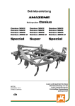
Diese Maschine ist mit Warnbildzeichen (Sicherheitsaufklebern) ausgestattet. Die Aufkleber mit den
entsprechenden Erläuterungen sind im folgenden aufgeführt und in der Gesamtabbildung dargestellt:
1
3
6
3 2 5
5
Bild 1-1
1. Achtung! Alle Schutzvorrichtungen vor Beginn der
Arbeit in Schutzstellung bringen.
16641358_de 10/2004
9
D
2. Vor allen Wartungs- und Reparaturarbeiten müssen
Sie die entsprechende Anleitung lesen! Sämtliche
Wartungs-, Reparatur- und Einstellarbeiten nur bei
Stillstand der Maschine durchführen. Motor abstellen und Zündschlüssel abziehen!
3. Halten Sie Abstand vom rotierenden Kreisel. Niemand darf sich bei laufender Schwadmaschine in
unmittelbarer Umgebung der Maschine befinden!
Vor dem Einschalten der Zapfwelle vergewissern,
daß niemand vom Kreisel erfaßt werden kann!
4. Die vorgeschriebene Zapfwellendrehzahl
nmax = 540 min-1 darf nicht überschritten werden.
5. Vorsicht beim Abstellen der Maschine! Nicht in den
Bereich des Abstellfußes treten - Quetschgefahr!
16641358_de 10/2004
6. Vor Inbetriebnahme die Betriebsanleitung und die
Sicherheitsvorschriften lesen und beachten!
10
D
Warnbildzeichen USA
1. Gefahr durch rotierende Antriebswelle
5. Gefahr durch bewegende Teile
6. Vor Intriebnahme die Betriebsanleitung und die
Sicherheitsvorschriften lesen und beachten!
16641358_de 10/2004
11
D
1.7
Zugelassene Bediener
Jugendliche unter 16 Jahren dürfen den Kreiselschwader nicht bedienen.
Der Halter der Maschine muß dem Bediener die Betriebsanleitung zugänglich machen und sich vergewissern, daß dieser sie gelesen und verstanden hat. Erst dann darf der Bediener die Maschine in
Betrieb nehmen. Die Zuständigkeiten für die unterschiedlichen Tätigkeiten an der Maschine müssen
klar festgelegt und eingehalten werden. Es dürfen keine Unklarheiten bezüglich der Kompetenzen
bestehen, denn dadurch kann die Sicherheit der Benutzer gefährdet werden.
Der Halter muß dafür sorgen, daß nur autorisierte Personen an der Maschine arbeiten. Er ist im Arbeitsbereich der Schwadmaschine Dritten gegenüber verantwortlich.
1.8
Allgemeine Sicherheits- und Unfallverhütungsvorschriften
Grundregel:
Überprüfen Sie vor jeder Inbetriebnahme den Kreiselschwader und den Traktor auf Verkehrs- und
Betriebssicherheit! Beachten Sie neben den Hinweisen in dieser Betriebsanleitung die allgemein gültigen Sicherheits- und Unfallverhütungsvorschriften.
1. Die angebrachten Warn- und Hinweisschilder geben wichtige Hinweise für den gefahrlosen Betrieb. Beachten Sie diese Hinweise für Ihre eigene Sicherheit!
2. Machen Sie sich vor Arbeitsbeginn mit allen Einrichtungen und Betätigungselementen und deren
Funktionen vertraut. Vergewissern Sie sich, daß alle Schutzeinrichtungen ordnungsgemäß angebaut sind.
3. Die Bekleidung des Benutzers sollte eng anliegen. Vermeiden Sie weite Kleidung! Tragen Sie festes
Schuhwerk!
4. Halten Sie den Kreiselschwader sauber! Brandgefahr!
5. Beachten Sie beim Benutzen öffentlicher Verkehrswege:
die gesetzlichen Straßenverkehrsbestimmungen,
die zulässigen Achslasten und Gesamtgewichte und
die zulässigen Transportabmessungen,
und halten Sie die zulässigen Transportgeschwindigkeit für Anbaugeräte (max. 40km/h) ein
Verlassen Sie während der Fahrt niemals den Fahrerstand!
6. Kreiselschwader für Straßenfahrt in vorgeschriebenen Zustand bringen und nach Vorschrift des
Herstellers verriegeln!
7. Überprüfen und befestigen Sie die Transportausrüstung und die Beleuchtungs-, Warn- und Schutzeinrichtungen!
8. Betätigungselemente (Seile, Ketten und Gestänge) fernbetätigter Einrichtungen müssen so verlegt
sein, daß sie in allen Transport- und Arbeitsstellungen keine unbeabsichtigten Bewegungen auslösen können!
9. Kreiselschwader vorschriftsmäßig ankuppeln und an den vorgeschriebenen Vorrichtungen befestigen und sichern! Beim An- und Abkuppeln des Kreiselschwaders an oder vom Traktor ist besondere Vorsicht nötig!
12
16641358_de 10/2004
1.8.1 Allgemeines
D
10. Bringen Sie die Stützeinrichtungen beim An- und Abbauen in die jeweils erforderliche Stellung.
Achten Sie auf ausreichende Standfestigkeit, und stellen Sie den Kreiselschwader nur auf ebenem und festem Untergrund ab.
11. Bringen Sie die Ballastgewichte, wenn erforderlich, immer vorschriftsmäßig an den dafür vorgesehenen Befestigungspunkten an!
12. Lassen Sie den Motor nicht in geschlossenen Räumen laufen!
13. Kontrollieren Sie den Nahbereich (Kinder!) vor dem Anfahren und vor der Inbetriebnahme!
Achten Sie auf ausreichende Sicht!
14. Das Mitfahren auf dem Kreiselschwader während der Transportfahrt ist nicht gestattet!
15. Passen Sie die Fahrgeschwindigkeit immer den Umgebungsverhältnissen an! Vermeiden Sie bei
Berg- und Talfahrten sowie Querfahrten zum Hang plötzliches Kurvenfahren!
16. Angehängte Geräte und Ballastgewichte beeinflussen das Fahrverhalten und die Lenk- und Bremsfähigkeit! Achten Sie auf ausreichende Lenk- und Bremsfähigkeit!
17. Berücksichtigen Sie bei Kurvenfahrten die Weite der Ausladung und die Schwungmasse des
Kreiselschwaders!
18. Kreiselschwader nur in Betrieb nehmen, wenn alle Schutzvorrichtungen angebracht und in Schutzstellung sind!
19. Der Aufenthalt im Arbeits- und Gefahrenbereich ist verboten!
20. Halten Sie sich nicht im Dreh- und Schwenkbereich des Kreiselschwaders auf!
21. An fremdkraftbetätigten Teilen (z.B. hydraulischen) befinden sich Quetsch- und Scherstellen!
22. Sichern Sie vor dem Verlassen des Traktors Ihren Kreiselschwader! Senken Sie den
Kreiselschwader ganz ab! Schalten Sie den Motor aus, und ziehen Sie den Zündschlüssel ab!
23. Zwischen Traktor und Kreiselschwader darf sich niemand aufhalten, wenn das Fahrzeug nicht
durch die Feststellbremse und Unterlegkeile gegen Wegrollen gesichert ist!
24. Beachten Sie die zulässige Achslast und das Gesamtgewicht sowie die zulässigen Transportabmessungen!
1.8.2 Angehängte Geräte
1.
2.
3.
Vor dem An- und Abbau von Geräten an die Ackerschiene müssen Sie die Bedienungseinrichtung
der Traktorhydraulik in die Stellung bringen, bei der unbeabsichtigtes Heben oder Senken ausgeschlossen ist!
Sie müssen die Anbaukategorien von Traktor und Gerät unbedingt aufeinander abstimmen!
Im Bereich der Ackerschiene besteht Verletzungsgefahr durch Quetsch- und Scherstellen!
16641358_de 10/2004
13
D
1.8.3 Zapfwellenbetrieb
16641358_de 10/2004
1. Verwenden Sie nur die vom Hersteller vorgeschriebenen Gelenkwellen!
Achten Sie auf richtige Montage und Sicherung der Gelenkwelle!
Schutzrohr und Schutztrichter der Gelenkwelle müssen ordnungsgemäß und in einwandfreiem Zustand angebracht sein! Gelenkwellenschutz durch Einhängen der Ketten maschinen- und
schlepperseitig gegen Mitlaufen sichern!
Achten Sie bei Gelenkwellen auf die vorgeschriebenen Rohrüberdeckungen in Transport- und
Arbeitsstellung!
2. Bei Arbeiten mit der Gelenkwelle darf sich niemand im Bereich der drehenden Gelenkwelle aufhalten!
3. An- und Abbau der Gelenkwelle nur bei ausgeschalteter Zapfwelle, abgestelltem Motor und abgezogenem Zündschlüssel durchführen!
Abgekoppelte Gelenkwelle auf der vorgesehenen Halterung ablegen!
Stecken Sie die Schutzhülle nach dem Abbau der Gelenkwelle auf den Zapfwellenstummel!
4. Der Zapfwellenschutz muß ordnungsgemäß und in einwandfreiem Zustand angebracht sein! Stellen Sie vor dem Einschalten der Zapfwelle sicher, daß die gewählte Drehzahl und Drehrichtung
der Traktor-Zapfwelle mit der zulässigen Drehzahl und Drehrichtung des Gerätes übereinstimmt!
Achten Sie darauf, daß sich vor dem Einschalten der Zapfwelle niemand im Gefahrenbereich des
Gerätes befindet!
5. Schalten Sie die Zapfwelle nie bei ausgeschaltetem Motor ein!
6. Zapfwelle immer abschalten, wenn zu große Abwinklungen auftreten oder wenn Sie sie nicht
benötigen!
7. Achtung! Nach dem Abschalten der Zapfwelle besteht Gefahr durch nachlaufende Schwungmasse!
Während dieser Zeit nicht zu nahe an das Gerät herantreten! Erst wenn das Gerät völlig stillsteht,
darf daran gearbeitet werden.
8. Reinigen, Schmieren oder Einstellen des zapfwellengetriebenen Gerätes oder der Gelenkwelle
nur bei abgeschalteter Zapfwelle, abgestelltem Motor und abgezogenem Zündschlüssel!
9. Schäden sofort beseitigen, bevor mit dem Gerät gearbeitet wird!
14
D
1.8.4 Hydraulikanlage
1. Achtung! Die Hydraulikanlage steht unter hohem Druck!
2. Kontrollieren Sie die Hydraulikschlauchleitungen regelmäßig, und tauschen Sie sie bei Beschädigung, spätestens jedoch alle 6 Jahre aus! Die Austauschschlauchleitungen müssen den technischen
Anforderungen des Geräteherstellers entsprechen! Verwenden Sie nur Originalteile!
3. Senken Sie vor Arbeiten an der Hydraulikanlage Geräte und Aggregate ab. Machen Sie erst dann
die Anlage drucklos, und stellen Sie den Motor ab.
4. Verwenden Sie bei der Suche nach Leckstellen geeignete Hilfsmittel. Verletzungsgefahr!
5. Beim Anschließen von Hydraulikzylindern ist auf den vorgeschriebenen Anschluß der Hydraulikschläuche zu achten!
Beim Anschluß der Hydraulikschläuche an die Traktor-Hydraulik ist darauf zu achten, daß die Hydraulik sowohl traktor- als auch geräteseitig ohne Druck ist!
6. Kennzeichnen Sie die Kupplungsmuffen und -stecker bei hydraulischen Funktionsverbindungen
zwischen Schlepper und Gerät, damit Fehlverbindungen ausgeschlossen sind!
Wenn Sie die Anschlüsse vertauschen, kehrt sich die Funktion der Bauteile um (z.B. Heben/Senken). Unfallgefahr!
7. Unter hohem Druck austretende Flüssigkeiten (Hydrauliköl) können die Haut durchdringen und
schwere Verletzungen verursachen! Bei Verletzungen sofort einen Arzt aufsuchen! Infektionsgefahr!
1.8.5 Reifen
1. Achten Sie bei Arbeiten an den Reifen darauf, daß der Kreiselschwader sicher abgestellt und
gegen Wegrollen gesichert ist! Unterlegkeile!
2. Das Montieren von Reifen und Rädern setzt ausreichende Kenntnisse und vorschriftsmäßiges
Montagewerkzeug voraus!
3. Reparaturarbeiten an und Montage von Reifen und Rädern dürfen nur Fachkräfte mit den dafür
geeigneten Werkzeugen durchführen!
4. Luftdruck regelmäßig kontrollieren! Vorgeschriebenen Luftdruck beachten!
16641358_de 10/2004
15
D
1.9
Sicherheit bei Nichtgebrauch und Unterstellung
1. Stellen Sie den Kreiselschwader an einem sicheren Ort unter.
2. Erlauben Sie Kindern niemals das Spielen auf dem Kreiselschwader oder um dem Kreiselschwader
herum.
3. Kuppeln Sie den Kreiselschwader immer nur auf festem, trockenem und ebenem Untergrund an
oder ab. Dies verringert die Gefahr des Umkippens bzw. Einsinkens in weichen Untergrund oder
Schlamm.
4. Legen Sie die abgekoppelte Gelenkwelle auf der vorgesehenen Halterung ab!
5. Sichern Sie den Kreiselschwader durch Unterlegkeile gegen Wegrollen.
6. Stellen Sie den Kreiselschwader nur mit abgesenktem Kreisel ab (Kippgefahr, Unfallgefahr durch
Zinken)!
1.10 Wartung
1. Instandsetzungs-, Wartungs- und Reinigungsarbeiten und die Beseitigung von Funktionsstörungen
sind grundsätzlich nur bei abgeschaltetem Antrieb, gesichertem Schlepper und stillstehendem Motor vorzunehmen! Zündschlüssel abziehen!
2. Muttern und Schrauben regelmäßig auf festen Sitz prüfen und ggf. nachziehen! Halten Sie die
angegebenen Drehmomente ein!
3. Bei Wartungsarbeiten am angehobenen Kreiselschwader diesen stets mit geeigneten Abstützelementen sichern!
4. Beim Auswechseln von Arbeitswerkzeugen geeignetes Werkzeug und Handschuhe benutzen.
5. Öle, Fette und Filter ordnungsgemäß entsorgen!
6. Vor Arbeiten an der elektrischen Anlage stets die Stromzufuhr abklemmen!
7. Unterliegen Schutzeinrichtungen einem Verschleiß, sind sie regelmäßig zu kontrollieren und rechtzeitig auszutauschen.
8. Bei Ausführung elektrischer Schweißarbeiten an Traktor und angebautem Kreiselschwader Kabel
an Generator und Batterie abklemmen!
9. Vermeiden Sie das Reinigen des Kreiselschwaders mit aggressiven Waschzusätzen. Blanke Metallflächen, z.B. Hydraulikzylinder können korridieren.
16
16641358_de 10/2004
Richtungsbezeichnungen („rechts“, „links“, „vorne“, „hinten“) sind in Fahrtrichtung zu verstehen.
Der Drehsinn ist wie folgt definiert:
Drehsinn rechts = im Uhrzeigersinn,
Drehsinn links = gegen den Uhrzeigersinn,
Drehungen um eine senkrechte Achse, von oben nach unten gesehen,
Drehungen um eine waagrechte Achse, rechtwinklig zur Fahrtrichtung, von links nach rechts gesehen,
Drehungen von Schrauben, Muttern u.ä. immer von der Betätigungsseite aus gesehen.
D
1.11 Sicherheitshinweise für den Kreiselschwader
1. Allgemeine Sicherheitshinweise sind in dieser Dokumentation und in der Unfallverhütungsvorschrift
VSG 1.1 vom 01.01.2000 der Landwirtschaftlichen Berufsgenossenschaften enthalten.
2. Überprüfen Sie vor dem ersten Einsatz die Gelenkwelle, und passen Sie sie gegebenenfalls an
Ihren Schlepper an (siehe Kap. „Anpassen der Gelenkwelle“)!
3. Reifendruck von 1,5 bar regelmäßig überprüfen.
4. Vor jeder Transportfahrt:
Zapfwelle abschalten
Stillstand der Kreisel abwarten
Kreiselschwader in Transportstellung bringen
korrekte Verriegelung kontrollieren
Hydraulik-Absperrhahn schließen
5. Vergewissern Sie sich, daß beim Heben und Senken des Kreisels niemand von der Maschine
erfaßt werden kann!
6. Reparaturen an vorgespannten Energiespeichern (Federn, Druckspeicher etc.) setzen ausreichende Kenntnisse sowie vorschriftsmäßiges Montagewerkzeug voraus und dürfen nur in Fachwerkstätten vorgenommen werden!
7. Vor allen Wartungs- und Reparaturarbeiten müssen Sie die entsprechende Anleitung lesen!
Sämtliche Wartungs-, Reparatur- und Einstellarbeiten nur bei Stillstand des Kreiselschwaders durchführen; Motor abstellen und Zündschlüssel abziehen!
8. Halten Sie Abstand vom rotierenden Kreisel. Niemand darf sich bei laufendem Kreiselschwader in
unmittelbarer Umgebung des Kreiselschwaders befinden! Vor dem Einschalten der Zapfwelle vergewissern, daß niemand vom Kreisel erfaßt werden kann.
9. Die vorgeschriebene Zapfwellendrehzahl nmax = 540 min-1 darf nicht überschritten werden!
10.Treten Sie nicht zwischen den Traktor und den Kreiselschwader. Einklemm- und Quetschgefahr!
11.Wenn Sie den Kraftheber betätigen, müssen Sie außerhalb des Hubbereichs der Dreipunktaufhängung bleiben!
12.Nach ca. 5 Betriebsstunden alle Schraubenverbindungen prüfen und gegebenenfalls nachziehen.
Drehmoment beachten!
13.Beim Abstellen der Maschine Gelenkwelle in die Aufnahme (Pfeil links) legen!
16641358_de 10/2004
17
D
1.12 Vorschriften für die Straßenfahrt
Nur für die Bundesrepublik Deutschland gültig!
Die Straßenverkehrs-Zulassungs-Ordnung (StVZO) schreibt vor, daß alle Anbau- und Anhängegeräte
mit Rückstrahlern und elektrischer Beleuchtung versehen werden müssen. Zur Kenntlichmachung der
scharfen Ecken und Kanten sind die Außenkonturen an Vorder- und Rückseite der Maschine durch rotweiß gestreifte Warnflächen von vorn und hinten gut sichtbar zu markieren.
Beachten Sie bei Fahrten auf öffentlichen Straßen die Gesetzesvorschriften über Breitenmarkierung,
Beleuchtung usw. Bei eventueller Überbreite müssen Sie eine Sondergenehmigung einholen.
16641358_de 10/2004
Beachten Sie darüberhinaus die Gesetzesvorschriften im „Merkblatt für Anbaugeräte“. Unter anderem
werden hier bei jedem Belastungsfall mindestens 20% des Schlepper-Leergewichtes als verbleibende
Vorderachslast verlangt.
18
D
2
Technische Daten
2.1
Allgemein
T yp
6598
Anbauart
Arme abn eh mbar
An h än gun g an die dreh bare Ackersch ien e
Stan dard
Ackersch ien e (An bau Kat l+ll möglich )
Option
Maß e / Gew ichte
Arbeitsbreite
4,20 m
Tran sportbreite
2,10 m
Län ge
4,75 m (3,9 m)
Gewich t
570 kg
Kreisel / Arme / Zinken
An zah l Kreisel
1
An zah l Arme pro Kreisel
11
An zah l Zin ken pro Arm
4
Zin ken arme
gebogen
Kreisel Höh en fein verstellun g
mech an isch
Hydraulisch er Aush ub für den Tran sport/Vorgewen de
Zin ken verlustsich erun g
Stan dard
Option
Räder unter den Kreiseln
Starre Tan demach sen - 18 x 8,50-8 Imp., 4PR
Stan dard
Sicherheitszubehör
Beleuch tun g
Option
Warn tafeln
Option
Gelen kwelle - Doppelweitwin kelgelen kwelle
2.2
Stan dard
Geräuschmessung
Der Emissions-Schalldruckpegel wurde in Übereinstimmung mit EN 31201 und EN 31204 gemessen.
16641358_de 10/2004
A-bewerteter äquivalenter Schalldruckpegel
Traktor
Traktor und Schw ader
Kabin en fen ster offen
76,6 dB(A)
83,5 dB(A)
Kabin en fen ster gesch lossen
74,2 dB(A)
75,0 dB(A)
19
D
3
Betrieb
3.1
Anbau an den Traktor
Gefahr!
Sämtliche Arbeiten nur bei Stillstand der
Maschine durchführen! Motor abstellen
und Zündschlüssel abziehen!
A
Bild 3-2
B
Beleuchtungskabel anschließen
Stützfuß einklappen.
Achtung!
Zum An- und Abkuppeln der Hydraulikleitung den Absperrhahn schließen und
Traktor-Hydraulik auf „Freigang” stellen.
Bei Verwendung eines Zugpendels oder einer starren Ackerschiene muß vor dem ersten Anbau folgendes geprüft werden:
Die Bohrung „X“ muß mind. so groß sein, daß sich der
Bolzen „B“ nicht verklemmen kann und beschädigt
wird. Das heißt, daß der Bolzen in alle Richtungen um
30° frei schwenkbar sein muß (Bild 3-3).
Bild 3-3
20
16641358_de 10/2004
Bild 3-1
Kreiselschwader an die Ackerschiene montieren
Bei der Zusatzausrüstung „Unterlenkermontage“ auf sicheres Verriegeln der Klappstecker achten!
Unterlenkerhöhe: ca. 400 mm Abstand vom Boden einstellen (Bild 3-1)
Mit der Verstellspindel „A“ die Maschine waagerecht/leicht nach vorn geneigt einstellen (Bild 3-2)
Während des Einsatzes die Unterlenker hydraulisch verriegeln, damit genügend Freiraum für die
Gelenkwelle bestehen bleibt!
Kreiselschwader mit Bolzen „B“ an die Zugmaschine anhängen und mit Federstift sichern (Bild 4-9)
Gelenkwelle an die Traktorzapfwelle anschließen
Schutzrohr mit Kette gegen Mitdrehen sichern
Stützfuß hochschwenken und verriegeln
Den Hydraulik-Remoteanschluß verbinden (ein
doppelwirkendes Steuergerät)
Achtung!
Achten Sie darauf, daß die Hydraulikleitungen sich nicht verklemmen, scheuern
oder hängenbleiben.
D
USA / Kanada- Abreißkette
Für Kreiselschwader, die in USA und Kanada verwendet werden, ist es Pflicht, den Kreiselschwader mit einer Abreißkette an der Zugmaschine zu sichern.
USA/Kanada Zusatzabsperrhahn
Nur als Anbauhilfe verwenden. Absperrhahn in Arbeitstellung immer öffnen (Bild 3-3a).
3.2
Bild 3-3a
Anpassen der Gelenkwelle
Die Länge der Gelenkwelle wurde werkseitig so gewählt, daß diese zu fast allen Schleppertypen paßt.
Nur in Ausnahmefällen ist bei einzelnen Traktoren eine
Korrektur der Gelenkwellenlänge erforderlich. Die
Gelenkwellenlänge ist vor dem ersten Einsatz folgendermaßen zu überprüfen:
Gefahr!
Sämtliche Arbeiten nur bei abgeschaltetem Motor und Stillstand der Maschine
durchführen. Zündschlüssel abziehen!
Bild 3-4
Gelenkwelle auseinanderziehen, und die beiden
Hälften auf die Zapfwelle stecken
Die beiden Wellenhälften nebeneinander halten
und prüfen, ob bei angehobener und abgesenkter
Schwadmaschine oder bei Kurvenfahrt
- noch mindestens 150 mm Überdeckung (b)
vorhanden ist und ob
- die Gelenkwelle nicht auf Block sitzt
(Mindestabstand (a) = 20 mm) (Bild 3-4)
Bei einer evtl. notwendigen Kürzung Schiebe- und
Schutzrohre je um das gleiche Maß absägen
Rohrenden entgraten, Späne entfernen, Gleitstellen gut einfetten
Wurde die Gelenkwelle gekürzt, so muß beim Betrieb mit einem anderen Schlepper die Mindestüberdeckung und der Mindestabstand erneut geprüft
werden
16641358_de 10/2004
21
D
3.3
Umstellen von Transport- in
Arbeitsstellung
Gefahr!
Sämtliche Arbeiten nur bei Stillstand der
Maschine durchführen! Motor abstellen
und Zündschlüssel abziehen!
Bild 3-5
Kreiselschwader hydraulisch ablassen
Federsteckersicherung ziehen (Bild 3-11)
Schutzbügel herunterklappen (Bild 3-9)
Zinkenarme aufstecken und arretieren (Bild 3-7)
Verdrehsicherung entriegeln und sichern (Bild 36)
Schwadtuch in gewünschte Position bringen
Auf spielfreie Befestigung des Schwadtuches achten. Die Knebelschraube „Y“ unter gleichzeitiger
Schwenkbewegung des Schwadformers anziehen
und mit Bügel „X“ kontern (Bild 3-8)
X
Bild 3-8
3-7
22
Bild 3-8
Y
16641358_de 10/2004
Bild 3-6
D
3.4
f
Umstellen von Arbeits- in
Transportstellung
Gefahr!
Sämtliche Arbeiten nur bei abgeschaltetem Motor und Stillstand der Maschine
durchführen. Zündschlüssel abziehen!
Umstellung für die Straßenfahrt:
a
b
d
Bild 3-9
c
o
Schwadformer (a) herausziehen, Schwadtuch nach
oben drehen, Schwadformer einschieben und mit
Knebelschraube und Kontermutter (b) sichern (Bild
3-9 und 3-6)
Auf spielfreie Befestigung des Schwadtuches achten. Die Knebelschraube „Y“ unter gleichzeitiger
Schwenkbewegung des Schwadformers anziehen
und mit Bügel „X“ kontern (Bild 3-8)
Beide Schutzbügel einklappen (c). Dazu Schutzbügel (c) nach vorne ziehen (o), hochklappen und
in Führungstasche einrasten lassen (s) (Bild 3-10)
und mit Federstecker sichern (Bild 3-11).
Überstehende Zinkenträger abnehmen
und
auf den hinteren Querträger (d) stecken (Bild3-9)
Kreiselsicherung (f) abstecken und sichern (Bild 36 und 3-9)
s
Bild 3-10
Bild 3-11
16641358_de 10/2004
23
D
3.5
Einsatz der Maschine
Die Fahrgeschwindigkeit so wählen, daß das Erntegut sauber und vollständig aufgenommen wird. Die
Zapfwellendrehzahl darf 540 min-1 nicht überschreiten und ist dem Zustand des Futters anzupassen.
Die Rutschkupplung nicht länger als 10 Sekunden ansprechen lassen. Bei Überlastung Fahrgeschwindigkeit und Zinkenhöhe anpassen.
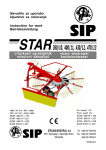
Folgende Arbeiten können Sie mit der Schwadmaschine ausführen (Bild 3-12):
Einfachschwad
Nachtschwad
Schwadwenden
Doppelschwad
Mehrfachschwad
Mehrfachschwad
16641358_de 10/2004
Bild 3-12
24
D
3.6
Abstellen der Maschine
Hinweis:
Bei Abbau des Kreiselschwa-ders mit einem Zugpendel ist Kap. 4.4 zu beachten
Maschine in untere Stellung absenken
Achtung!
Beim Anheben des Unterlenkers ist auf die
Gelenkwelle zu achten!
Unterlenker anheben, und Stützfuß nach unten
schwenken
Unterlenker entlasten
Gefahr!
Sämtliche Arbeiten nur bei Stillstand der
Maschine durchführen! Motor abstellen
und Zündschlüssel abziehen!
Maschine gegen Wegrollen sichern
Achtung!
Zum An- und Abkuppeln der Hydraulikleitung den Absperrhahn schließen und die
Traktorhydraulik auf „Freigang“ stellen!
Bild 3-13
a = geöffnet
b = geschlossen
Kugelhahn schließen (Bild 3-13)
Hydraulik und gegebenenfalls Elektrik abkoppeln
Die Sicherungskette entfernen, und Gelenkwelle
auf der Gelenkwellenstütze ablegen
Verbindungsbolzen abziehen
16641358_de 10/2004
25
D
4
Einstellungen
Gefahr!
Sämtliche Arbeiten nur bei Stillstand der
Maschine durchführen! Motor abstellen
und Zündschlüssel abziehen!
4.1
Kreisel Höheneinstellung
Während der Arbeit wird die Maschine hydraulisch
ausgehoben und abgesenkt. Das Absenken erfolgt bis
zur voreingestellten Tiefe. Maßgebend für den Abstand
der Zinken zum Boden sind die Bodenbeschaffenheit
sowie die spezifischen Einsatzbedingungen.
Einstellung der Höhe:
m
Bild 4-1
k
Hinweis:
Bitte beachten Sie, daß die Einstellung der
Zinkentiefe einen erheblichen Einfluß auf
die Futterverschmutzung und die Lebensdauer der Maschine hat
Maschine ganz ausheben
Gefahr!
Sämtliche Arbeiten nur bei Stillstand der
Maschine durchführen! Motor abstellen
und Zündschlüssel abziehen!
Gefahr!
Kreiselschwader vor Wegrollen sichern!
Bild 4-2
a = geöffnet
Kugelhahn schließen (Bild 4-2)
Arretierklappe „k“ für die Verstellmutter umlegen
Mutter „m“ (SW 65) in die gewünschte Position drehen (Bild 4-1)
Mutter „m“ mit Arretierklappe „k“ sichern!
Deichselneigung anpassen, siehe Kap. 4.4
16641358_de 10/2004
b = geschlossen
26
D
Gefahr!
Sämtliche Arbeiten nur bei Stillstand der
Maschine durchführen! Motor abstellen
und Zündschlüssel abziehen!
4.2
Schwadformer Einstellung
Um den Schwadformer in die gewünschte
Arbeitslage zu bringen, werden die Schrauben „Z“
mit der SW 17 nur leicht gelöst (Bild 4-5)
Schwadtuch in gewünschte Lage schieben
Schrauben „Z“ anziehen (Bild 4-5)
Bügel „X“ öffnen und Knebelschraube „Y“ lösen
(Bild 4-6)
Schwadformer in gewünschten Abstand zu den
Federzinken schieben
Knebelschraube „Y“ anziehen und mit Bügel „X“
sichern (Bild 4-6)
Z
Bild 4-5
Y
X
16641358_de 10/2004
Bild 4-6
27
D
Gefahr!
Sämtliche Arbeiten nur bei Stillstand der
Maschine durchführen! Motor abstellen
und Zündschlüssel abziehen!
4.3
l
Feineinstellung quer zur
Fahrtrichtung
Sollten beim Betrieb die Federzinkenspitzen unterschiedlich tief eingreifen, muß die Einstellung wie folgt korrigiert
werden (Bild 4-7):
Maschine in Arbeitsstellung bringen
Reifenluftdruck, auf beiden Seiten 1,5 bar, kontrollieren
Alle drei Schrauben „k“ (M12) nur leicht lösen
Achse mit Einstellschraube „l“ so verschieben, daß
der Zinkenabstand zum Boden rechts und links
gleich groß ist
Schrauben „k“ (M12) mit 85 Nm wieder anziehen.
k
Bild 4-7
4.4
Die Deichsel sollte immer so eingestellt sein, daß die
Maschine leicht nach vorne geneigt ist. Die Einstellung erfolgt über die Verstellspindel „A“ (Bild 4-8). Dabei ist darauf zu achten, daß der Mindestabstand von
50 mm zwischen Bolzen „B“ und Gelenkwelle „W“
nie unterschritten wird (Bild 4-9).
A
Bild 4-8
W
Abstand
min. 50 mm
Einstellung der Deichsel
Bei An- und Abbau der Maschine ohne hydraulischen Unterlenker erfolgt die Entlastung der Deichsel über die Verstellspindel „A“ (Bild 4-8)
Die Kreiselneigung wird ebenfalls über die Verstellspindel „A“ eingestellt
Bild 4-9
28
16641358_de 10/2004
B
D
5
Wartung der Maschine
Gefahr!
Sämtliche Arbeiten nur bei Stillstand der
Maschine durchführen! Motor abstellen
und Zündschlüssel abziehen!
Hinweis!
Vor dem ersten Einsatz alle Schmierstellen kontrollieren und gegebenenfalls laut
Schmierplan nachschmieren.
5.1
Allgemeine Wartung
Nach fünf Betriebsstunden ist der Kreiselschwader
genau zu kontrollieren. Sämtliche Schrauben, besonders die der Federzinken-, Kreiselarm- und Achsbefestigungen, überprüfen und ggf. nachziehen.
Anziehdrehmomente für:
Federzinkenbefestigung = 90 Nm
Kreiselarmbefestigung = 110 Nm
Der vorgeschriebene Luftdruck von 1,5 bar ist stets
einzuhalten! Bei einem eventuellen Radwechsel darf
die Radmutter nur mit 20 Nm angezogen werden, um
die Kunststoffringe nicht zu beschädigen.
Gelenkwellenpflege:
Durch eine regelmäßige Wartung erreichen Sie eine
lange Lebensdauer der Gelenkwelle. Vor jedem Einsatz muß die Funktion der Gelenkwelle und ihre
Sicherheitsteile überprüft werden. Nach der Saison alle
Teile gründlich reinigen und abschmieren.
16641358_de 10/2004
29
D
Einwinterung:
Zur Einwinterung der Maschine sind folgende Arbeiten durchzuführen:
Maschine gründlich reinigen
Alle Schraubverbindungen kontrollieren und Schrauben nachziehen
Schadhafte Bauteile instandsetzen oder austauschen
Farbschäden ausbessern
Die Maschine nach Schmierplan abschmieren (Bild 5-1 und 5-2)
Reifenluftdruck prüfen
Schmierplan:
Im Schmierplan sind alle Schmierstellen gekennzeichnet. Eine lange Lebensdauer der Maschine erreichen Sie durch Einhaltung der von uns angegebenen Wartungs- und Schmierintervalle. Verwenden
Sie Schmierfette K2k nach DIN 51825, z.B. „Deutzer Öl“, „HFL300W“ oder „Shell Retinax A“. Vor
dem Ansetzen der Fettpresse müssen deren Schmiernippel und der Aufsatznippel gesäubert werden.
30h
30h
Bild 5-1
Bild 5-2
30
*
16641358_de 10/2004
= 8h
D
6
Sonder- und
Zusatzausrüstungen
Gefahr!
Sämtliche Arbeiten nur bei abgeschaltetem Motor und Stillstand der Maschine
durchführen. Zündschlüssel abziehen!
6.1
Zinkenverlustsicherung
Die flexiblen Kunststoffhalter können leicht festgeklemmt
und wieder gelöst werden. Wenn jetzt ein Zinken abbricht, wird er am Nebenzinken festgehalten. Er geht
nicht verloren und kann dadurch auch nachfolgende
Maschinen, wie z. B. Häcksler nicht beschädigen.
Für eine gute Schwadablage müssen beide Zinkenschenkel parallel zueinander verlaufen. Dies muß auch
nach der Montage der Zinkenverlustsicherung gewährleistet sein (Bild 6-1).
Bild 6-1
6.2
Ackerschiene
Als Sonderzubehör gibt es eine frei drehbare Ackerschiene „KAT I + II“ (Bild 6-2).
Bild 6-2
6.3
16641358_de 10/2004
Bild 6-3
Stützrad
Damit auch in stark unebenem Gelände die Grasnarbe nicht verletzt wird, und andererseits kein Erntegut
liegen bleibt, kann als Zusatzausrüstung ein Stützrad
ganz nahe dem Zinkeneingriff angebaut werden (Bild
6-3).
31
D
Warntafen mit Anbauteilen
Die Straßenverkehrs-Zulassungsordnung (StVZO)
schreibt vor, daß alle angebauten und angehängten
landwirtschaftlichen Arbeitsgeräte bei Fahrt auf öffentlichen Straßen mit Warntafeln versehen werden müssen. Die Warntafeln mit Anbauteilen können als Set
passend zum jeweiligen Maschinentyp von
Kverneland Gottmadingen bezogen werden.
Eine ausführliche Montageanleitung liegt dort bei.
Beleuchtungssatz
Die Straßenverkehrs-Zulassungsordnung (StVZO)
schreibt vor, daß alle angebauten und angehängten
landwirtschaftlichen Arbeitsgeräte bei Fahrt auf öffentlichen Straßen mit Beleuchtung versehen werden müssen. Ein passender Beleuchtungssatz kann von
KVERNELAND GOTTMADINGEN bezogen werden.
Eine ausführliche Montageanleitung liegt dort bei.
6.4
Höhenverstellbarer Stützfuß
16641358_de 10/2004
Um das An- und Abhängen an Traktoren mit Zugpendel
zu erleichtern, bietet Kverneland einen höhenverstellbaren Stützfuß, als Sonderausstattung an.
32
D
7
Fehler- und Störungs-Abhilfeliste
Störung
Abhilfe
1
Kreisel lässt auf ein er Seite Futter liegen un d
tauch t auf der an deren Seite zu tief in den
Boden ein
z Fein ein stellun g quer zur Fah rtrich tun g,
Kap. 4.3
2
Kreisel lässt über die gesamte Breite Futter
liegen
z Kreiselh öh en ein stellun g, Kap. 4.1
3
Futter wird stark versch mutzt
z Kreisel h öh er ein stellen , Kap. 4.1
4
Masch in e arbeitet bei grosser Gesch win digkeit
un sauber
z Kreisel tiefer stellen , Kap. 4.1
z Kreiseln eigun g mit Deich sel verstellen ,
Kap. 4.4
z Klein ere Gan gstufe wäh len
5
Kreisel zieh t Futter n ach – un saubere
Sch wadform
z Dreh zah l reduzieren
z Sch wadtuch ein stellen , Kap. 4.2
6
Gelen kwellen kupplun g sprich t h äufig an
z Gesch win digkeit reduzieren
z Kreisel arbeitet zu tief, Kap. 4.1
7
Geräusch bildun g beim Arbeiten
z Arbeitsorgan e un d Sch raubverbin dun gen kon trollieren , Kap. 5
8
Masch in e sackt bei Tran sportfah rt ab
z Kugelh ah n sch liessen ,
Kap. 3.4
16641358_de 10/2004
33
D
A
Anhang
A.1
Anziehdrehmomente für Schraubenverbindungen
Alle Schraubenverbindungen sind gemäß untenstehender Tabelle anzuziehen, wenn keine anderen
Anziehdrehmomente angegeben sind. Bei dieser Maschine ist „8.8“ sowohl Standard- als auch Mindestqualität der verwendeten Schrauben.
Achtung!
Sicherungsschrauben und -muttern müssen mit einem um 10% höheren Wert angezogen
werden.
Gewin de
8.8
10.9
12.9
Nm
lbf-ft*
Nm
lbf-ft*
Nm
lbf-ft*
mm
in ch
M3
1,9
(11,5)
1,8
(16,0)
2,1
(18,6)
6
1/4
M4
2,9
(25,5)
4,1
(36,5)
4,9
(43,5)
8
5/16
M5
5,7
(50,5)
8,1
(71,5)
9,7
(86,0)
9
23/64
M6
9,9
7,3
14
10,3
17
12,5
10
13/32
M8
24
17,7
34
25,0
41
30,3
14
9/16
M10
48
35,4
68
50,2
81
59,8
17
11/16
M12
85
62,7
120
88,6
145
107
19
3/4
M14
135
99,6
190
140
225
166
22
7/8
M16
210
155
290
214
350
258
24
M18
290
214
400
295
480
354
27
M20
400
295
570
421
680
502
30
640
473
M20x1,5
30
1 3/16
550
406
770
568
920
679
32
1 17/64
M24
700
517
980
723
1180
871
36
1 27/64
M27
1040
767
1460
1077
1750
1291
41
1 79/128
M30
1410
1041
1980
1461
2350
1734
46
1 13/16
M33
1910
1410
2700
1996
3200
2362
50
1 31/32
M36
2450
1808
3450
2546
4150
3063
55
2 11/64
M39
3200
2362
4500
3321
5400
3985
60
2 3/8
8.8
< M16
> M16
808
830
N/mm2
lbf/sq.in . 117,222 120,414
10.9
12.9
1040
1220
150,880
176,994
Bemerkun gen
*Werte
in
121/128
Klamm1 9/128
er
=
l
b
f-in .
1 3/16
M22
Zugfestigkeit
34
Sch lüsselweite
16641358_de 10/2004
An zieh momen t für Materialqualitäten n ach DIN ISO 898
(trocken )
FR
Déclaration CE de conformité
conformément aux directives CE
-
Machine 98 / 37 / CEE (22.06.1998)
La machine
Produit fabriqué
Modèle :
N° d’ident.
N° de série
N° de machine
Année de construction
: andaineur rotatif
: SwatMaster 4231 / Andex 423 T / Taarup 9042 T
: 6598
: 19 : 1011 : 2004
a été conçue, fabriquée et manufacturée conformément aux directives européennes stipulées ci-dessus,
sous la responsabilité exclusive de
Kverneland Group Gottmadingen GmbH & Co. KG
Hauptstraße 99
D-78244 Gottmadingen
Les normes harmonisées suivantes ont été appliquées :
-
Normes DIN EN 292/1 et EN 292/2, Sécurité des machines, outils et installations, notions
fondamentales, principes généraux de conception
Une documentation technique complète est à disposition.
L’instruction de service relative à la présente machine est disponible
-
en version originale
en versions traduites
: allemand
: anglais, français
Gottmadingen 20.10.2004
16641358_fr 10/2004
Rudolf Mayer
Directeur General
1
16641358_fr 10/2004
FR
2
FR
Avant-propos
La présente instruction de service vous informe en détail sur la mise en marche et l’entretien de votre
nouvel andaineur rotatif. Elle comprend également des consignes de sécurité qui permettent une utilisation
en toute sécurité. En plus des équipements livrables et des variantes, l’instruction de service décrit en
détail des équipements supplémentaires qui ne font pas partie de la fourniture normale.
Ce manuel a été réalisé pour vous permettre d’obtenir les meilleurs résultats de votre andaineur rotatif
Kverneland.
La performance de votre machine dépend en grande partie d’un usage approprié et d’un entretien
soigneux. Avant la première mise en marche de la machine, prenez le temps de lire attentivement cette
instruction de service et gardez-la à portée de main. Ainsi vous éviterez des accidents, conserverez le
bénéfice de la garantie et disposerez toujours d’une machine fonctionnelle et en parfait état de marche.
Kverneland s’efforce sans cesse d’améliorer ses produits. Aussi se réserve-t-elle le droit d’apporter à
ses machines toutes les modifications et les perfectionnements nécessaires. Mais elle ne s’engage pas
à transformer ni à modifier les machines déjà livrées.
Si vous avez des questions après avoir lu l’instruction de service, veuillez contacter votre revendeur
responsable.
Bonne récolte avec votre andaineur rotatif !
Prière de lire l’instruction de service et les consignes de sécurité avant la mise en service et de les
mettre en pratique !
Kverneland Group Gottmadingen GmbH & Co. KG
Hauptstraße 99
D-78244 Gottmadingen
Tél. ++49-7731-788-0
Veuillez entrer les données relatives à votre machine ci-dessous :
16641358_fr 10/2004
Modèle de machine
Numéro de série
Première mise en service le
:...........................................................
:...........................................................
:...........................................................
3
FR
Table des matières
1
Sécurité ........................................................................... 6
1.1
1.2
1.3
1.4
1.5
1.6
1.7
1.8
Pour votre sécurité ............................................................................................ 6
Consignes de sécurité utilisées dans ce manuel .......................................... 6
Plaque signalétique .......................................................................................... 7
Utilisation conforme à l’emploi prévu ........................................................... 7
Responsabilité ................................................................................................... 7
Autocollants de sécurité et symboles d’avertissement ................................ 9
Utilisateurs autorisés ..................................................................................... 12
Prescriptions générales de sécurité et de prévention des accidents ...... 12
1.8.1 Généralités .......................................................................................... 12
1.8.2 Appareils traînés................................................................................. 13
1.8.3 Utilisation de la prise de force ......................................................... 14
1.8.4 Système hydraulique .......................................................................... 15
1.8.5 Pneus .................................................................................................... 15
1.9 Sécurité en cas de non-utilisation et de mise à l’abri ............................... 16
1.10 Entretien .......................................................................................................... 16
1.11 Consignes de sécurité pour l’andaineur rotatif ........................................ 17
1.12 Prescriptions pour le transport routier ........................................................ 18
2
Caractéristiques techniques ............................................ 19
2.1
2.2
3
Caractéristiques générales .......................................................................... 19
Mesure de bruit ............................................................................................. 19
Utilisation ...................................................................... 20
Accrochage au tracteur ................................................................................ 20
Adaptation de l’arbre à cardan ................................................................. 21
Changer de position : position de transport / position de travail ......... 22
Changer de position : position de travail / position de transport ......... 23
Utilisation de la machine .............................................................................. 24
Stationnement de la machine ...................................................................... 25
16641358_fr 10/2004
3.1
3.2
3.3
3.4
3.5
3.6
4
FR
4
Réglages ....................................................................... 26
4.1
4.2
4.3
4.4
5
en hauteur des toupies ................................................................. 26
de la planche d’andainage ......................................................... 27
précis transversalement au sens de roulement ......................... 28
du timon .......................................................................................... 28
Maintenance de la machine ............................................ 29
5.1
6
Réglage
Réglage
Réglage
Réglage
Maintenance générale ................................................................................. 29
Equipéments spéciaux et supplémentaires ...................... 31
6.1
6.2
6.3
6.4
Protection contre la perte de dents ............................................................. 31
Barre d’attelage............................................................................................. 31
Roue-support .................................................................................................. 31
Béquille réglable en hauteur ....................................................................... 32
7
Anomalies et remèdes .................................................... 33
A
Annexe .......................................................................... 34
A.1 Couples de serrage pour assemblages par boulons .............................. 34
16641358_fr 10/2004
5
FR
1
Sécurité
1.1
Pour votre sécurité
Lors de la remise de l’andaineur rotatif, le revendeur vous a expliqué le fonctionnement et l’entretien de
la machine. Lisez cette instruction de service avant d’utiliser pour la première fois la machine et respectez
impérativement les consignes de sécurité. Les points particulièrement importants sont désignés par un
pictogramme.
Dans la présente instruction de service, ce symbole vous signale toutes les consignes de
sécurité importantes. Respectez ces consignes à la lettre et redoublez d’attention lorsque
vous voyez ce symbole.
L’anaideur rotatif est doté de dispositifs de protection qui sont contrôlés par la caisse agricole de
prévoyance contre les accidents. Néanmoins, les maniements inappropriés ou abusifs sont source de
danger :
pour l’intégrité et la vie de l’utilisateur et pour les personnes et les animaux se trouvant à proximité de
la machine,
pour la machine et les autres biens du conducteur et de tiers,
pour l’efficacité de travail de la machine.
Toutes les personnes concernées par l’installation, la mise en service ainsi que l’utilisation et l’entretien
de la machine doivent avoir lu avant de commencer le travail les consignes de sécurité suivantes avec
attention et elles doivent les observer.
Il en va de votre sécurité !
1.2
Consignes de sécurité utilisées dans ce manuel
Symboles utilisés pour les consignes de sécurité :
Danger !
Ce symbole indique qu’il existe un danger réel de blessures ou de mort. Si vous voyez ce
symbole dans l’instruction de service, prenez toutes les mesures de sécurité nécessaires.
Remarque :
Remarques et informations importantes.
6
16641358_fr 10/2004
Attention !
Ce symbole signale les risques de dommages matériels et attire votre attention sur les
conséquences financières et juridiques évidentes (par ex. garantie, responsabilité etc.).
FR
1.3
Plaque signalétique
La plaque signalétique indiquant le modèle de la machine et le numéro de série est fixée sur le front du
cadre principal à gauche.
Remarque :
Entrez les données se trouvant sur la plaque signalétique dans le petit cadre qui se trouve
sur la page 3 de ce manuel.
1.4
Utilisation conforme à l’emploi prévu
L’andaineur rotatif est exclusivement conçu et prévu pour l’utilisation dans les travaux agricoles usuels et
en particulier pour le traitement des herbes fauchées et couchées sur le sol.
Toute autre utilisation est considérée non-conforme à l’emploi prévu. Le fabricant ne peut être tenu
responable des dommages en découlant. L’utilisateur porte l’entière responsabilité !
Le respect des conditions de fonctionnement, d’entretien et de maintien spécifiées par le fabricant font
également partie de l’utilisation conforme. L’utilisation, l’entretien et le maintien de l’andaineur rotatif ne
doivent être réalisés que par des personnes ayant lu et compris ces conditions et qui sont au courant
des dangers.
Les règlements pour la prévention des accidents du travail applicables ainsi que les règles diverses,
générales et reconnues de la technique de sécurité, de la médecine du travail et du code de circulation
routière sont à respecter.
Attention !
Le fabricant décline toute responsabilité pour les dommages résultant de modifications
apportées arbitrairement à la machine.
1.5
Responsabilité
Chaque personne ayant à effectuer des travaux avec ou sur la machine doit lire cette instruction de
service et en observer les instructions. La machine doit être utilisée uniquement à des fins conformes à
l’emploi prévu (voir chapitre 1.4).
1. En utilisant la machine, se conformer exclusivement aux instructions spécifiées dans la documentation
valable !
Celle-ci peut être composée des documents suivants :
16641358_fr 10/2004
Instructions de montage
Instruction de service
Feuilles supplémentaires
7
FR
2. Se conformer strictement aux règles et prescriptions suivantes :
les règlements locaux pour la prévention des accidents du travail en vigueur,
les règles reconnues de la technique de sécurité, de la médecine du travail et du code de
circulation routière,
les consignes de sécurité et les limites de fonctionnalité qui se trouvent dans les instructions
techniques.
3. N’utiliser que des outils et dispositifs appropriés et en état impeccable pour effectuer des travaux sur
la machine.
4. N’utiliser que des pièces et du matériel (pièces de rechange, équipement supplémentaire, lubrifiants
etc.) correspondant au moins aux prescriptions du fabricant de la machine et les utiliser selon les
prescriptions (les couples de serrage spécifiés inclus).
Une pièce correspond aux prescriptions quand il s’agit d’une pièce originale ou d’une pièce
explicitement autorisée du fabricant de la machine.
5. Les dommages résultant de modifications arbitraires effectuées sur la machine ne seront pas couverts
par les conditions de garantie et de responsabilité offertes par le fabricant.
16641358_fr 10/2004
Attention !
Observer les conditions d’emploi mentionnées ci-dessus. Toute négligence de ces règles
de la part de l’utilisateur entraîne la nullité et l’invalidité de la responsabilité du fabricant.
Tous dommages et les conséquences qui en résultent incombent entièrement et exclusivement
à l’utilisateur.
8
FR
1.6
Autocollants de sécurité et symboles d’avertissement
Attention !
Une sécurité effective signifie que vous êtes familiarisé avec tous les autocollants de sécurité.
Ceci concerne le genre et le lieu des risques et surtout les mesures de sécurité à prendre.
Soyez toujours vigilant et bien conscient des risques.
Cette machine est dotée de symboles d’avertissement (autocollants de sécurité). Les autocollants avec
les explications correspondantes sont énumérés ci-après et représentés sur la figure d’ensemble.
1
3
6
3 2 5
5
Fig. 1-1
1. Attention ! Avant de commencer à travailler, mettre
tous les dispositifs de protection en place.
16641358_fr 10/2004
9
FR
2. Avant tous travaux de maintenance et de réparation,
lire les instructions correspondantes ! Effectuer tous
les travaux de maintenance, de réparation et de
réglage seulement lorsque la machine est à l’arrêt.
Arrêter le moteur et retirer la clé de contact !
3. Tenez-vous à distance de la toupie en rotation.
Lorsque l’andaineur est en marche, personne ne
doit se trouver à proximité de la machine ! Avant
de mettre la prise de force en circuit, s’assurer que
personne ne peut être saisi par la toupie.
4. La vitesse de rotation de la prise de force prescrite
nmax = 540 t/min ne doit pas être dépassée.
5. Attention lors de l’arrêt de la machine ! Ne pas
mettre le pied près du pied d’arrêt - risque
d’écrasement !
16641358_fr 10/2004
6. Prière de lire l’instruction de service et les consignes
de sécurité avant la mise en service et de les mettre
en pratique !
10
FR
Autocollants de sécurité Etats-Unis
1. Danger par la rotation de l’arbre d’entraînement!
5. Danger par des pièces en mouvement!
6. Avant la mise en route lire la notice de
fonctionnement et observer les prescriptions de
sécurité.
16641358_fr 10/2004
11
FR
1.7
Utilisateurs autorisés
La conduite de l’andaineur rotatif est interdite aux jeunes de moins de seize ans.
Le détenteur de la machine doit mettre l’instruction de service à la disposition de l’utilisateur et s’assurer
que celui-ci l’a lue et comprise. Seulement alors l’utilisateur peut prendre en charge le fonctionnement
de la machine. Les compétences propres à chacune des différentes fonctions de la machine doivent
être fixées et respectées. Les compétences doivent être nettement définies afin de garantir la sécurité
des utilisateurs.
Le détenteur doit également prendre garde à ce que seules des personnes autorisées travaillent sur la
machine. Il est responsable vis-à-vis de tiers dans la zone de travail de l’andaineur rotatif.
1.8
Prescriptions générales de sécurité et de prévention des accidents
Règle fondamentale :
Avant chaque mise en service de l’andaineur rotatif et du tracteur, vérifier qu’ils correspondent aux
prescriptions de sécurité routière et fonctionnelle ! Respectez, en plus des consignes contenues dans
cette instruction de service, les prescriptions générales de sécurité et de prévention des accidents en
vigueur.
1. Les plaques d’avertissement et les symboles de danger sur la machine vous donnent des indications
importantes pour un fonctionnement sans risque. Respectez ces indications pour votre sécurité !
2. Avant d’utiliser la machine, familiarisez-vous avec toutes les installations, les éléments de commande
ainsi que leurs fonctions. Vérifiez que tous les dispositifs protecteurs soient montés correctement.
3. Evitez les vêtements flottants. L’utilisateur devra porter des vêtements qui collent au corps et des
chaussures solides !
4. Maintenez l’andaineur rotatif en état propre pour éviter tout risque d’incendie !
5. Lorsque vous empruntez les routes publiques respectez
le code de la route,
la charge maximale autorisée par essieu et le poids total autorisé,
la réglementation sur les dimensions de transport.
Respectez également la vitesse de transport admissible pour les outils portés (max. 40 km/h).
Quand vous êtes en route, ne quittez jamais le poste de conduite!
6. Préparez l’andaineur rotatif pour le transport routier selon les prescriptions applicables et verrouillezle suivant les instructions du fabricant.
7. Vérifiez les équipements de transport tels que p. ex. l’éclairage, la signalisation et remontez tous les
carters de protection.
8. Les dispositifs de commande (cordes, chaînes, tringles etc.) des équipements télécommandés doivent
être placés de manière à ce qu’aucune position de transport ou de travail ne puisse provoquer des
mouvements inavertis.
9. Accouplez l’andaineur rotatif suivant les prescriptions et fixez et assurez-le aux endroits prévus et
autorisés. Faites particulièrement attention lors de l’accrochage et du décrochage de l’andaineur
rotatif sur le tracteur.
12
16641358_fr 10/2004
1.8.1 Généralités
FR
10. Lors de l’accrochage et du décrochage placez la béquille de support dans la position
correspondante. S’assurer que la machine est suffisamment stable. Placer l’andaineur rotatif
toujours sur un sol plan et ferme.
11. Toujours fixer les poids de lest suivant les prescriptions aux points de fixation prévus à cet effet !
12. Ne laissez pas marcher le moteur dans des locaux fermés !
13. Avant le démarrage et la mise en marche de la machine, contrôlez les abords (enfants !) !
Assurez-vous d’avoir une visibilité suffisante !
14. Il est interdit de circuler à bord de l’andaineur rotatif pendant le transport !
15. La vitesse de marche doit toujours correspondre aux conditions environnantes. En montant, en
descendant ou en conduisant sur une butte en sens transversal, éviter de tourner brusquement !
16. La conduite, la capacité de freinage et la dirigeabilité sont influencées par les appareils traînés et
par les poids de lest. Pour cette raison, il faut faire particulièrement attention à la capacité de
freinage et à la dirigeabilité.
17. Pendant les virages faites attention au rayon de pivotement et à l’inertie de l’andaineur rotatif !
18. Veillez à ce que tous les dispositifs de protection et les carters soient bien en place avant de
mettre en service l’andaineur rotatif.
19. Il est interdit de se tenir dans la zone de travail et de danger de la machine !
20. Ne pas se tenir dans le rayon de braquage ou de rotation de l’andaineur rotatif !
21. Il y a risque d’écrasement et de coupure par des pièces commandées par une force extérieure
(p. ex. hydrauliques).
22. Avant de quitter le tracteur, bloquez l’andaineur rotatif. Abaissez au maximum l’andaineur rotatif.
Arrêtez le moteur et retirez la clé de contact !
23. Personne ne doit se trouver entre le tracteur et l’andaineur rotatif sans que ceux-ci soient bloqués
par le frein à main du tracteur et des cales contre tout déplacement.
24. Respectez la charge maximale autorisée par essieu et le poids total autorisé ainsi que la
réglementation sur les dimensions de transport.
1.8.2 Appareils traînés
1.
2.
3.
Avant le montage ou le démontage des appareils à la barre d’attelage, mettez le dispositif de
commande de l’hydraulique du tracteur dans une position qui empêche toute levée ou descente
par inadvertance !
Les catégories d’attelage du tracteur et de l’appareil doivent impérativement correspondre les
unes aux autres !
Dans la zone de la barre d’attelage il y a risque de blessures dues aux points d’écrasement et de
coupure !
16641358_fr 10/2004
13
FR
1.8.3 Utilisation de la prise de force
16641358_fr 10/2004
1. N’utiliser que les arbres à cardan prescrits par le fabricant !
Veiller à ce que l’arbre à cardan soit monté et fixé correctement !
L’arbre à cardan doit être équipé d’un tube et de cloches de protection conformément aux prescriptions
étant en bon état ! Fixer la protection de l’arbre à cardan contre une rotation simultanée en accrochant
des chaînes sur le côté machine et le côté tracteur.
Faire attention au recouvrement prescrit des tubes de l’arbre à cardan en position de transport et de
travail !
2. Veiller à ce que personne ne se trouve dans la zone autour de l’arbre à cardan lorsque vous
travaillez avec celui-ci !
3. Débrayer la prise de force, arrêter le moteur et retirer la clé de contact avant de connecter ou de
déconnecter l’arbre à cardan.
L’arbre à cardan décroché doit être placé sur le support prévu.
Mettre en place le manchon de protection sur la prise de force, dès que l’arbre à cardan n’y est
plus raccordé.
4. Faire toujours attention à la mise en place correcte et l’état impeccable du manchon de protection
de la prise de force ! Avant d’enclencher la prise de force, faire attention à ce que le nombre de
tours et le sens de rotation de la prise de force du tracteur correspondent à ceux de l’appareil de
récolte. Avant d’enclencher la prise de force, veiller à ce que personne ne se tienne dans la zone
de danger de l’appareil de récolte.
5. Ne jamais enclencher la prise de force avec le moteur arrêté !
6. Toujours débrayer la prise de force avant un virage important ou lorsqu’elle n’est pas nécessaire !
7. Attention ! Du fait de son inertie, la prise de force continue à tourner après le débrayage ! Rester à
l’écart de l’appareil durant ce laps de temps. N’intervenir sur celui-ci qu’après immobilisation complète.
8. Nettoyage, graissage ou réglage de l’appareil entraîné par la prise de force ou de l’arbre à cardan
ne doivent être effectués que lorsque la prise de force est débrayée, le moteur arrêté et la clé de
contact retirée.
9. En cas de dommages, les réparer immédiatement avant de travailler avec l’appareil de récolte.
14
FR
1.8.4 Système hydraulique
1. Attention ! Le système hydraulique se trouve sous haute pression !
2. Contrôler régulièrement les conduites hydrauliques et les remplacer en cas de dommages et au
moins tous les 6 ans. Les conduites remplacées doivent correspondre aux prescriptions techniques
du constructeur de l’appareil. N’utiliser que des pièces originales !
3. Avant de travailler sur le système hydraulique, abaisser les appareils et les groupes. Enlever seulement
maintenant la pression du système et couper le moteur.
4. Lors de la recherche de fuites, utiliser des moyens appropriés afin d’éliminer les risques de blessures.
5. En raccordant les vérins hydrauliques, il faut faire attention à utiliser les raccords hydrauliques prévus.
En raccordant les conduites hydrauliques sur l’hydraulique du tracteur, il faut faire attention à ce que
l’hydraulique du tracteur comme celle de l’andaineur soit sans pression.
6. Pour le raccordement hydraulique entre le tracteur et l’appareil de récolte, les raccords mâles et
femelles doivent être repérés pour éviter des erreurs de raccordement.
En cas d’inversion des raccords, les fonctions sont inversées (p. ex. montée/descente) - risque
d’accident !
7. Du liquide s’échappant sous pression (huile hydraulique) peut pénétrer dans la peau, causant de
sérieuses blessures. Dans un tel cas, consulter immédiatement un médecin - risque d’infection grave !
1.8.5 Pneus
1. Lors du travail sur les pneumatiques veiller à ce que l’andaineur rotatif soit bien bloqué et calé.
2. Le montage des pneumatiques et des roues suppose que celui qui l’effectue dispose des connaissances
requises et de l’outillage adéquat.
3. Les réparations sur les pneumatiques et les roues ne doivent être effectuées que par des personnes
spécialisées équipées d’outils appropriés.
4. Contrôler régulièrement la pression de gonflage ! Respecter la pression de gonflage prescrite !
16641358_fr 10/2004
15
FR
1.9
Sécurité en cas de non-utilisation et de mise à l’abri
1. Mettre l’andaineur rotatif à l’abri dans un lieu sûr.
2. Ne pas laisser jouer des enfants sur l’andaineur rotatif ou à proximité de celui-ci.
3. Accoupler ou désaccoupler l’andaineur rotatif toujours sur un sol stable, sec et plan. Ainsi, le risque
que la machine se renverse ou s’effondre dans un fond tendre ou dans la boue est réduit.
4. L’arbre à cardan décroché doit être placé sur le support prévu à cet effet.
5. Assurer l’andaineur rotatif contre tout déplacement inaverti au moyen de cales de freinage.
6. Ne garer l’andaineur rotatif qu’avec toupie rabattue (danger de renversement, resp. danger
d’accident par les dents).
1.10 Entretien
C’est le sens de marche du tracteur qui détermine les indications de sens (« droite », « gauche », « avant »
et « arrière »).
Le sens de rotation est défini comme suit :
rotation à droite = dans le sens des aiguilles d’une montre,
rotation à gauche = dans le sens contraire des aiguilles d’une montre,
mouvements rotatifs autour d’un axe vertical - vue de haut en bas,
mouvements rotatifs autour d’un axe horizontal qui se trouve à angle droit par rapport au sens de
marche - vue de gauche à droite,
en ce qui concerne les vis, écrous etc., c’est la position de l’opérateur qui détermine le sens.
16641358_fr 10/2004
1. N’effectuer des travaux de remise en état, d’entretien ou de nettoyage, et ne remédier à des
défaillances de fonctionnement que lorsque l’entraînement et le moteur sont arrêtés et le tracteur est
bloqué ! Retirer la clé de contact !
2. Contrôler régulièrement le bon serrage des écrous et vis et, si nécessaire, les resserrer ! Tenir
compte des couples de serrage indiqués !
3. Ne pas effecteur des travaux d’entretien sur l’andaineur rotatif relevé sans avoir mis par mesure de
sécurité des supports appropriés !
4. Pour le remplacement des outils, utiliser des outils appropriés et porter des gants !
5. Eliminer les huiles, graisses et filtres usés selon les prescriptions !
6. Avant de travailler sur le système électrique, débrancher la conduite de courant !
7. Contrôler régulièrement toutes les protections qui peuvent s’user, et les changer à temps.
8. Pour effectuer des travaux de soudage électrique sur le tracteur ou sur l’andaineur rotatif porté, il faut
débrancher le câble de l’alternateur triphasé et de la batterie!
9. Eviter de nettoyer l’andaineur rotatif avec des additifs agressifs. Les surfaces métalliques nues, p.
ex. les vérins hydrauliques, peuvent corroder.
16
FR
1.11 Consignes de sécurité pour l’andaineur rotatif
1. Vous trouverez des consignes de sécurité générales dans cette documentation et dans le règlement
pour la prévention des accidents du travail VSG 1.1 de la caisse agricole de prévoyance contre les
accidents.
2. Contrôler l’arbre à cardan avant la première mise en route ; il peut être nécessaire de l’adapter à
votre tracteur (voir chap. Adaptation de l’arbre à cardan) !
3. Vérifier régulièrement la pression de gonflage (1,5 bar) !
4. Avant chaque transport :
débrayer la prise de force,
attendre l’arrêt des toupies,
mettre l’andaineur rotatif en position de transport,
s’assurer que le verrouillage est effectif,
fermer le robinet d’arrêt du système hydraulique.
5. Veiller à ce que personne ne se trouve dans la zone d’action de l’andaineur lorsque la toupie est
soulevée, abaissée ou mise en position de travail.
6. Les réparations sur des réservoirs d’énergie sous précontrainte (ressorts, accumulateur de pression
etc.) supposent des connaissances suffisantes ainsi que des outils conformes aux instructions et ne
doivent être effectuées que dans des ateliers spécialisés.
7. Avant tous travaux de maintenance et de réparation, il faudra que vous lisiez les instructions
correspondantes !
Effectuer tous les travaux de maintenance, de réparation et de réglage seulement lorsque l’andaineur
rotatif est à l’arrêt ; arrêter le moteur et retirer la clé de contact !
8. Se tenir à distance de la toupie en rotation. Lorsque l’andaineur rotatif est en marche, personne ne
doit se trouver à proximité de cette machine ! Avant de mettre la prise de force en circuit, s’assurer
que personne ne peut être saisi par la toupie.
9. La vitesse de rotation de la prise de force prescrite nmax = 540 t/min ne doit pas être dépassée.
10.Ne pas se tenir entre le tracteur et l’andaineur rotatif. Risque de coincement et d’écrasement !
11.Lorsque vous actionnez le vérin hydraulique, vous devez rester en dehors de la zone de levage de
l’attelage à trois points !
12.Après env. 5 heures de service contrôler tous les assemblages par boulons et les resserrer si
nécessaire. Respecter le couple de serrage !
13.Au stationnement de la machine, poser l’arbre à cardan dans le logement prévu (flèche à gauche) !
16641358_fr 10/2004
17
FR
1.12 Prescriptions pour le transport routier
N’est valable qu’en République fédérale d’Allemagne !
Les prescriptions de l’arrêté ministériel en vue des véhicules routiers (StVZO) exigent que tous les outils
portés ou attelés doivent être pourvus de réflecteurs et d’un éclairage électrique. Afin de signaler les
angles et bords vifs, les contours extérieurs sur le côté avant et arrière de la machine doivent être
marqués de manière bien visible par des surfaces d’avertissement peints à bandes rouges et blanches.
Lorsque vous circulez sur des routes publiques, il faut respecter les prescriptions légales concernant la
signalisation de la largeur, l’éclairage etc. Il faut demander une autorisation exceptionnelle en cas de
dépassement de la largeur normale.
16641358_fr 10/2004
Observer de plus les prescriptions légales énumérées sur « Merkblatt für Anbaugeräte (Feuille informative pour outils portés) ». Il est entre autre obligatoire que la charge sur l’essieu avant restante soit d’au
moins 20% du poids à vide du tracteur pour tous les cas de charge.
18
FR
2
Caractéristiques techniques
2.1
Caractéristiques générales
T y pe
6598
Type d'attelage
bras amovibles
Attelage à la barre d'attelage orien table
stan dard
Barre d'attelage (mon tage Cat l+ll possible)
option
Dimensions / poids
Largeur de travail
4,20 m
Largeur de tran sport
2,10 m
Lon gueur
4,75 m (3,9 m)
Poids
570 kg
Toupies / bras / dents
Nombre de toupies
1
Nombre de bras par toupie
11
Nombre de den ts par bras
4
Bras à den ts
droits
Réglage précis en h auteur de la toupie
mécan ique
Sortie h ydraulique pour le tran sport/fourrière
Protection con tre la perte de den ts
stan dard
option
Roues en-dessous des toupies
Essieux-tan dem rigides - 18 x 8,50-8 Imp., 4PR
stan dard
Accessoires de sécurité
Eclairage
option
Plaques d'avertissemen t
option
Arbre à cardan - arbre à cardan double à gran d
an gle
2.2
stan dard
Mesure de bruit
Le niveau de pression acoustique émise a été mesuré conformément à EN 31201 et EN 31204.
16641358_fr 10/2004
Niveau de pression acoustique équivalent à évaluation A
T r acteur
T r acteur et andaineur
fe n ê tre de cabin e ouve rte
76,6 dB(A)
83,5 dB(A)
fe n ê tre de cabin e fe rmé e
74,2 dB(A)
75,0 dB(A)
19
FR
3
Utilisation
3.1
Accrochage au tracteur
Danger !
Tous les travaux ne doivent être effectués
que lorsque la machine est arrêtée !
Arrêter le moteur et retirer la clé de
contact !
A
Fig. 3-2
Raccorder les câbles de l’éclairage
Rabattre le pied d’appui
Attention !
Pour accrocher et décrocher la conduite
hydraulique, fermer le robinet d’arrêt et
régler l’hydraulique du tracteur sur
« suspension libre ».
20
16641358_fr 10/2004
Fig. 3-1
Monter l’andaineur rotatif à la barre d’attelage
Dans le cas de l’équipement supplémentaire
« montage de bras inférieurs » veillez à bien
verrouiller les esses d’essieu !
Hauteur du bras inférieur : env. 400 mm du sol
(fig. 3-1)
Régler la machine horizontalement/légèrement
inclinée vers l’avant au moyen de la broche de
réglage « A » (fig. 3-2)
Pendant l’utilisation, verrouiller les bras inférieurs
de façon hydraulique afin qu’un espace
suffisamment grand reste libre pour l’arbre à
cardan !
Accrocher l’andaineur rotatif au tracteur au moyen
du boulon « B » et fixer avec la goupille élastique
(fig. 4-9)
Raccorder l’arbre à cardan à la prise de force du
tracteur
Protéger le tube de protection contre la rotation
simultanée à l’aide de la chaîne
Rabattre le pied d’appui vers le haut et le verrouiller
Relier le raccordement à distance hydraulique (un
appareil de commande à effet double)
Attention !
Veiller à ce que les conduites hydrauliques
ne puissent pas être coincées, usées par
frottement ou s’accrocher.
FR
B
Lorsque vous utilisez un porte-outils ou une barre
d’attelage fixe, il faut effectuer les vérifications suivantes
avant de l’accrocher pour la première fois :
Le trou « X » doit être suffisamment grand afin que le boulon
« B » ne puisse pas être coincé et endommagé. Cela signifie
qu’il doit être possible de faire pivoter le boulon dans tous
les sens de 30° (fig. 3-3).
Chaîne de sécurité pour les Etats Unis et le Canada
Il est obligatoire de fixer l’andaineur rotatif avec une
chaîne de sécurité sur le tracteur lorsque l’andaineur rotatif
est utilisé dans les Etats Unis ou au Canada.
Fig. 3-3
Robinet d‘arrêt - USA/Canada
A n’utiliser que pour atteler la machine au tracteur. En
position de travail toujours laisser le robinet ouvert (fig. 33a).
3.2
Adaptation de l’arbre à cardan
La longueur de l’arbre à cardan a été choisie en usine de
telle sorte qu’elle convienne à presque tous les types de
tracteurs. Une correction de la longueur de l’arbre à cardan
sur les tracteurs n’est nécessaire que dans des cas d’exception.
La longueur de l’arbre à cardan doit être vérifiée comme suit
avant la première utilisation :
Fig. 3-3a
Danger !
Tous les travaux ne doivent être effectués
que lorsque la machine est arrêtée !
Arrêter le moteur et retirer la clé de
contact !
16641358_fr 10/2004
Etirer l’arbre à cardan et emboîter les deux semi-arbres
sur la prise de force.
Tenir les deux semi-arbres l’un à côté de l’autre et
vérifier, lorsque l’andaineur rotatif est soulevée ou
abaissée ou dans les virages, si :
- il y a encore au moins 150 mm de
recouvrement (b) et
- l’arbre à cardan ne se trouve pas sur le bloc
(distance minimum (a) = 20 mm) (fig. 3-4)
S’il faut raccourcir le tube coulissant et le tube de
protection, les scier de la même longueur.
Ebavurer les extrémités des tubes, éliminer les copeaux,
bien graisser les points de glissement.
Lorsqu’il fallait raccourcir l’arbre à cardan, il faut
contrôler une nouvelle fois le recouvrement minimum
et la distance minimum si l’andaineur rotatif est utilisé
avec un autre tracteur.
Fig. 3-4
21
FR
3.3
Changer de position : position de
transport / position de travail
Danger !
Tous les travaux ne doivent être effectués
que lorsque la machine est arrêtée !
Arrêter le moteur et retirer la clé de
contact !
Fig. 3-5
Abaisser l’andaineur rotatif hydrauliquement.
Tirer le mécanisme de sécurité (fig. 3-11)
Rabattre l’étrier de protection vers le bas (fig. 3-9).
Monter les bras de dents et les fixer (fig. 3-7).
Déverrouiller puis bloquer le dispositif de protection
contre toute rotation involontaire (fig. 3-6).
Mettre le drap d’andain dans la position souhaitée.
Faire attention à ce que le drap d’andain soit fixé
sans jeu. Serrer la vis à garret « Y » en pivotant en
même temps la planche d’andainage et bloquer
au moyen de l’étrier « X » (fig. 3-8).
Fig. 3-6
Fig. 3-7
22
Fig. 3-8
Y
16641358_fr 10/2004
X
FR
3.4
f
Changer de position :
position de travail / position
de transport
Danger !
Tous les travaux ne doivent être effectués
que lorsque la machine est arrêtée !
Arrêter le moteur et retirer la clé de
contact !
Conversion pour le transport routier :
a
b
d
Fig. 3-9
c
o
Fig. 3-10
s
Retirer la planche d’andainage (a), pivoter le drap
d’andain vers le haut, faire entrer la planche
d’andainage et la bloquer au moyen de la vis à
garret et du contre-écrou (b) (fig. 3-9).
Faire attention à ce que le drap d’andain soit fixé
sans jeu. Serrer la vis à garret
« Y » en pivotant en même temps la planche
d’andainage et bloquer au moyen de l’étrier « X »
(fig. 3-8) et assurer à l’aide de la fiche de sécurité
(fig. 3-11).
Replier les deux étriers de protection (c). Pour ce
faire, tirer les étriers de protection (c) vers l’avant
(o), les rabattre vers le haut et les faire enclencher
dans le dispositif de support (s) (fig. 3-10).
Enlever les supports de dents qui dépassent et les
monter sur le support transversal arrière (d) (fig. 39).
Fixer le dispositif de protection de la toupie (f) et le
bloquer (fig. 3-9).
Fig 3-11
16641358_fr 10/2004
23
FR
3.5
Utilisation de la machine
La vitesse de roulement doit être sélectionnée de sorte que le produit récolté est repris de façon propre
et intégrale. Le nombre de tours de la prise de force ne doit pas dépasser 540 t/min et doit être adapté
à l’état du fourrage. Ne pas laisser répondre l’accouplement patinant pendant plus de 10 secondes. En
cas de surcharge, la vitesse de roulement et la hauteur des dents doivent être adaptées.
Les travaux suivants peuvent être exécutés au moyen de l’andaineur rotatif :
Andain simple
Andain nocturne
Retournement
d’andains
Andain double
Andain multiple
16641358_fr 10/2004
Fig. 3-12
24
FR
3.6
Stationnement de la machine
Remarque :
Au démontage de l’andaineur rotatif avec
porte-outils observer le chap. 4.4
Abaisser la machine dans la position inférieure.
Attention !
Faire attention à l’arbre à cardan lors du
soulèvement du bras inférieur !
Soulever le bras inférieur et rabattre le pied d’appui
vers le bas.
Soulager le bras inférieur.
Danger !
Tous les travaux ne doivent être effectués
que lorsque la machine est arrêtée !
Arrêter le moteur et retirer la clé de
contact !
Bloquer la machine au moyen de cales de freinage.
Attention!
Pour connecter et déconnecter la conduite
hydraulique, fermer le robinet d’arrêt et
régler l’hydraulique du tracteur sur
« suspension libre ».
Fig. 3-13
a = ouvert
b = fermé
Fermer le robinet à tournant sphérique (fig. 3-13)
Déconnecter le système hydraulique et le système
électrique si présent.
Enlever la chaîne de sécurité et déposer l’arbre à
cardan sur son support.
Retirer le boulon de liaison.
16641358_fr 10/2004
25
FR
4
Réglages
Danger !
Tous les travaux ne doivent être effectués
que lorsque la machine est arrêtée !
Arrêter le moteur et retirer la clé de
contact !
4.1
Réglage en hauteur des toupies
Pendant le travail, la machine est soulevée et rabaissée
par hydraulique. L’abaissement se fait jusqu’à la
profondeur préréglée. La nature du terrain ainsi que
les conditions d’utilisation spécifiques sont décisives pour
la distance des dents par rapport au sol.
Réglage de la hauteur :
m
Fig. 4-1
k
Remarque :
Veuillez observer que le réglage de la
profondeur des dents a une influence
importante sur le degré de pollution du
fourrage et sur la durée de vie des dents.
Soulever la machine complètement au moyen de
l’appareil de commande à effet double.
Danger !
Tous les travaux ne doivent être effectués
que lorsque la machine est arrêtée !
Arrêter le moteur et retirer la clé de
contact !
Fig. 4-2
a = ouvert
b = fermé
26
Fermer le robinet à tournant sphérique (fig. 4-2).
Rabattre le clapet d’arrêt « k » pour l’écrou de
réglage.
Tourner l’écrou « m » (ouverture de clé 65) dans
la position souhaitée (fig. 4-1).
Fixer l’écrou « m » au moyen du clapet d’arrêt « k ».
Adapter l’inclinaison du timon, voir chap. 4.4.
16641358_fr 10/2004
Danger !
Protéger l’andaineur rotatif contre tout
déplacement !
FR
Danger !
Tous les travaux ne doivent être effectués
que lorsque la machine est arrêtée !
Arrêter le moteur et retirer la clé de
contact !
4.2
Réglage de la planche
d’andainage
Afin de positionner la planche d’andainage dans
la position de travail souhaitée, les vis
« Z » avec ouverture de clé 17 ne sont desserées
que légèrement (fig. 4-5).
Mettre le drap d’andain dans la position souhaitée
en le poussant.
Serrer les vis « Z » (fig. 4-5).
Ouvrir l’étrier « X » et desserrer la vis à garret « Y »
(fig. 4-6).
Mettre la planche d’andainage à la distance
souhaitée par rapport aux dents élastiques.
Serrer la vis à garret « Y » et bloquer au moyen de
l’étrier « X » (fig. 4-6).
Z
Fig. 4-5
Y
X
16641358_fr 10/2004
Fig. 4-6
27
FR
Danger !
Tous les travaux ne doivent être effectués
que lorsque la machine est arrêtée !
Arrêter le moteur et retirer la clé de
contact !
4.3
l
Réglage précis
transversalement au sens de
roulement
Lorsque les pointes des dents élastiques s’enfoncent
irregulièrement pendant l’utilisation, il faut corriger le réglage
de la manière suivante (fig. 4-7) :
Mettre la machine en position de travail.
k
Contrôler la pression de gonflage ; elle doit être de
1,5 bar sur les deux côtés.
Desserrer légèrement les trois vis « k » (M12).
Déplacer l’essieu à l’aide de la vis de réglage « l »
de telle manière que la distance des dents par
rapport au sol soit identique sur la gauche et la droite.
Reserrer les vis « k » (M12) avec un couple de
serrage de 85 Nm.
Fig. 4-7
A
4.4
Fig. 4-8
W
Distance
min. 50 mm
Réglage du timon
Il faut régler le timon de façon à ce que la machine soit
toujours légèrement inclinée vers l’avant. Le réglage
se fait à l’aide de la broche de réglage « A » (fig. 4-8).
Il faut veiller à ce que la distance minimum entre le
boulon « B » et l’arbre à cardan « W » ne soit jamais
inférieure à 50 mm (fig. 4-9).
En cas de connexion et déconnexion d’une
machine sans bras inférieur hydraulique, le
soulagement du timon est réalisé par la broche de
réglage « A » (fig. 4-8).
L’inclinaison de la toupie est réglée également au
moyen de la broche de réglage « A ».
Fig. 4-9
28
16641358_fr 10/2004
B
FR
5
Maintenance de la machine
Danger !
Tous les travaux ne doivent être effectués
que lorsque la machine est arrêtée !
Arrêter le moteur et retirer la clé de
contact !
Remarque !
Avant la première utilisation, contrôler tous
les points de graissage et les graisser si
nécessaire conformément au plan de
graissage.
5.1
Maintenance générale
Au bout de cinq heures de service il faut effectuer un
contrôle rigoureux sur l’andaineur rotatif. Contrôler et
si nécessaire serrer toutes les vis, en particulier celles
des fixations des dents élastiques, des bras de toupie
et des essieux.
Couples de serrage pour
la fixation des dents élastiques = 90 Nm
la fixation des bras de toupie = 110 Nm
La pression de gonflage prescrite de 1,5 bar doit
toujours être respectée ! Lors d’un changement de roue
éventuel, l’écrou de roue ne doit être serré qu’avec
20 Nm afin de ne pas endommager les bagues en
matière synthétique.
Entretien de l’arbre à cardan :
Un entretien régulier assure une longue durée de vie
de l’arbre à cardan. Avant chaque utilisation, il faut
contrôler le bon fonctionnement de l’arbre à cardan
et ses pièces de sécurité. En fin de saison, toutes les
pièces doivent être nettoyées et graissées
soigneusement.
16641358_fr 10/2004
29
FR
Hivernage :
Pour préserver la machine pendant l’hiver, les travaux suivants doivent être effectués :
Nettoyer la machine avec grand soin.
Contrôler tous les assemblages par boulons et resserrer les vis.
Réparer ou remplacer les éléments endommagés.
Réparer les dommages de peinture.
Graisser la machine conformément au plan de graissage (fig. 5-1 et 5-2).
Contrôler la pression de gonflage des pneus.
Plan de graissage :
Tous les points de graissage sont marqués sur le plan de graissage. Une longue durée de vie de la
machine est atteinte en respectant les intervalles de maintenance et de graissage indiqués. Utilisez les
graisses K2k selon DIN 51825, p. ex. « Deutzer Öl », « HFL300W » ou « Shell Retinax A ». Avant
d’utiliser la pompe à graisse, les graisseurs de celle-ci et le nipple correspondant doivent être nettoyés.
30h
30h
Fig. 5-1
Fig. 5-2
30
*
16641358_fr 10/2004
= 8h
FR
6
Equipéments spéciaux et
supplémentaires
Danger !
Tous les travaux ne doivent être effectués
que lorsque la machine est arrêtée !
Arrêter le moteur et retirer la clé de
contact !
6.1
Protection contre la perte de dents
Les supports flexibles en matière plastique peuvent être
serrés et desserrés facilement. Lorsqu’une dent se
casse, elle est maintenant retenue par la dent voisine.
Elle n’est pas perdue et ne risque ainsi pas
d’endommager les machines suivantes telles que les
hacheuses par exemple.
Fig. 6-1
Pour garantir une dépose impeccable de l’andain, les
deux côtés des dents doivent s’aligner en parallèle.
Ceci doit être garanti également après avoir monté la
protection contre la perte de dents (fig. 6-1).
6.2
Barre d’attelage
Une barre d´attelage librement orientable < CAT I +II
> est disponible en option (fig. 6-3).
Fig. 6-2
6.3
16641358_fr 10/2004
Fig. 6-3
Roue-support
Pour éviter tout grattage du sol en terrain accidenté et
pour qu’aucune parcelle de récolte ne puisse échapper
à l’action des dents de la machine, il est possible, en
équipement supplémentaire, de monter une rouesupport qui guide de très près, I’action des dents.(fig
6-3)
31
FR
Jeu de plaques d’avertissement complet
Le code de la route allemand prescrit que tous les
outillages agricoles ajoutés et mis en remorque doivent
être pourvus de plaques d’avertissement pour rouler
sur la voie publique. Il vous est possible d’acheter un
jeu de plaques d’avertissement adéquate avec le
matériel pour les fixer chez KVERNELAND
GOTTMADINGEN.
Des instructions de montage détaillées sont jointes à
l’équipement auxiliaire.
Jeu d’ampoules complet
Le code de la route allemand prescrit que tous les
outillages agricoles ajoutés et mis en remorque doivent
être éclairés pour rouler sur la voie publique. Il vous
est possible d’acheter un jeu d’ampoules adéquate
chez KVERNELAND GOTTMADINGEN.
Des instructions de montage détaillées sont jointes à
l’équipement auxiliaire.
6.4
Béquille réglable en hauteur
16641358_fr 10/2004
Afin de faciliter l’attelage et le désattelage des tracteurs avec un timon oscillant, Kverneland propose
comme équipement spécial une béquille réglable en
hauteur.
32
FR
7
Anomalies et remèdes
A n om alie
z R e m è de
1
Sur un côté, la toupie n e récolte pas
tout le fourrage et s'en fon ce trop
profon demen t dan s la terre sur
l'autre côté
z Réglage précis tran sversalemen t au sen s de
roulemen t,
ch ap. 4.3
2
La toupie n e récolte pas de fourrage z Réglage en h auteur des toupies,
sur toute la largeur
ch ap. 4.1
3
Le fourrage est fortemen t en crassé
z Mettre la toupie à un e h auteur plus élevée,
ch ap. 4.1
4
La mach in e n e travaille pas
correctemen t à gran de vitesse
z Mettre la toupie à un e h auteur plus faible,
ch ap. 4.1
z Régler l'in clin aison de la toupie au moyen du
timon , ch ap. 4.4
z Sélection n er un e vitesse plus petite
5
La toupie en traîn e du fourrage forme d'an dain in correcte
z Réduire la vitesse
z Régler le drap d'an dain , ch ap. 4.2
6
L'accouplemen t de l'arbre à cardan
réagit fréquemmen t
z Réduire la vitesse
z La toupie s'en fon ce trop profon demen t, ch ap.
4.1
7
Bruit an ormal pen dan t le travail
z Con trôler les organ es de travail et les
assemblages par boulon s,
ch ap. 5
8
La mach in e s'affisse pen dan t le
tran sport
z Fermer le robin et à tourn an t sph érique, ch ap.
3.4
16641358_fr 10/2004
33
FR
A
Annexe
A.1
Couples de serrage pour assemblages par boulons
Tous les assemblages par boulons doivent être serrés conformement au tableau ci-dessous, sauf indication
contraire. Pour cette machine, « 8.8 » représente à la fois la qualité standard et la qualité minimum des
vis utilisées.
Attention !
Lorsque des vis de fixation et des contre-écroux sont utilisées, le couple de serrage doit être
augmenté de 10%.
8.8
10.9
lbf-ft*
Nm
lbf-ft*
Nm
lbf-ft*
mm
in ch
M3
1,9
(11,5)
1,8
(16,0)
2,1
(18,6)
6
1/4
M4
2,9
(25,5)
4,1
(36,5)
4,9
(43,5)
8
5/16
M5
5,7
(50,5)
8,1
(71,5)
9,7
(86,0)
9
23/64
M6
9,9
7,3
14
10,3
17
12,5
10
13/32
M8
24
17,7
34
25,0
41
30,3
14
9/16
M10
48
35,4
68
50,2
81
59,8
17
11/16
M12
85
62,7
120
88,6
145
107
19
3/4
M14
135
99,6
190
140
225
166
22
7/8
M16
210
155
290
214
350
258
24
M18
290
214
400
295
480
354
27
M20
400
295
570
421
680
502
30
640
473
*valeur
en
121/128
paren 1 9/128 th èses
1 3/16 =lbf-in .
30
1 3/16
M22
550
406
770
568
920
679
32
1 17/64
M24
700
517
980
723
1180
871
36
1 27/64
M27
1040
767
1460
1077
1750
1291
41
1 79/128
M30
1410
1041
1980
1461
2350
1734
46
1 13/16
M33
1910
1410
2700
1996
3200
2362
50
1 31/32
M36
2450
1808
3450
2546
4150
3063
55
2 11/64
M39
3200
2362
4500
3321
5400
3985
60
2 3/8
Resist.á
la
traction
8.8
< M16
> M16
808
830
N/mm2
lbf/sq.in . 117,222 120,414
Remarques
12.9
Nm
M20x1,5
34
Ouverture de la
clé
10.9
12.9
1040
1220
150,880
176,994
16641358_fr 10/2004
Filetage
Couple pour les qualités de matériaux selon DIN ISO
898
( s ê ch e )
E
EU Declaration of Conformity
as defined by the EU directives
-
Implements 98 / 37 / EEC (22.06.1998)
The implement
product
type
identity no.
serial numbers
implement no.
year of construction
: Helipede Rotary Windrower
: SwatMaster 4231 / Andex 423 T / Taarup 9042 T
: 6598
: 19 : 1011 : 2004
was solely designed, constructed and manufactured, in accordance with the aforementioned EU directives,
by
Kverneland Group Gottmadingen GmbH & Co. KG
Hauptstraße 99
D-78244 Gottmadingen
The following harmonised norms were applied:
-
DIN EN 292/1 and EN 292/2, safety of implements, equipment and systems, basic terminology,
general principles for design
Complete technical documentation is available.
The operating instructions for the implement are available
-
in the original version:
in the languages:
: German
: English, French
Gottmadingen 20.10.2004
1664 1358_en 10/2004
Rudolf Mayer
General Manager
1
1664 1358_en 10/2004
E
2
E
Foreword
These operating instructions provide you with detailed information concerning system set up and
maintenance of your new Helipede Rotary Windrower. In addition, the instructions also include safety
instructions which ensure safe employment of the implement. The operating instructions contain
descriptions of all the available equipment, the various models and all of the special and additional
pieces of equipment which are not included in the normal scope of delivery.
These operating instructions are intended to enable you in getting the best possible use out of your new
Kverneland Helipede Rotary Windrower.
The performance of your implement depends to a great extent on correct use and careful maintenance.
For this reason, read the instructions carefully before the first system start up and always keep them
near at hand. By doing so, you will avoid accidents, preserve the manufacturer’s warranty and always
enjoy the advantages of an efficient and reliable implement.
KVERNELAND is continuously making every effort to improve their products. The company reserves
the right to make any alterations or improvements to the implement considered necessary. This, however,
does not obligate the company to modify implements which have already been supplied.
If you have any questions which are not covered by the operating instructions, please contact your
nearest dealer.
We hope you reap a bountiful harvest with the help of the Helipede Rotary Windrower!
Read and observe the operating and safety instructions before system start up!
Kverneland Group Gottmadingen GmbH & Co. KG
Hauptstraße 99
D-78244 Gottmadingen
Tel. ++49-7731-788-0
Fill in your implement details here:
1664 1358_en 10/2004
Implement type
Serial number
Initial start-up on
:..................................................................
:..................................................................
:...........................................................
3
E
Table of contents
1
Safety.............................................................................. 6
1.1
1.2
1.3
1.4
1.5
1.6
1.7
1.8
For your safety............................................................................................................. 6
Safety instructions contained in this manual ........................................................... 6
Nameplate ................................................................................................................... 7
Application as stipulated............................................................................................ 7
Liability and warranty................................................................................................. 7
Safety stickers and warning signs ............................................................................ 9
Authorized operators .............................................................................................. 12
General safety and accident prevention regulations ......................................... 12
1.8.1 General ............................................................................................... 12
1.8.2 Trailed implements ............................................................................. 13
1.8.3 Power take-off operation .................................................................. 14
1.8.4 Hydraulics ........................................................................................... 15
1.8.5 Tyres .................................................................................................... 15
1.9 Safety when implement is not in use or is in storage .......................................... 16
1.10Maintenance ............................................................................................................. 16
1.11Safety instructions for the Helipede Rotary Windrower .................................... 17
1.12Regulations for travelling on public roads ........................................................... 18
2
Technical specifications ................................................... 19
2.1 General ...................................................................................................................... 19
2.2 Noise level ................................................................................................................ 19
Operation ...................................................................... 20
3.1
3.2
3.3
3.4
3.5
3.6
Mounting to the tractor ............................................................................................ 20
Adjusting the cardan shaft ...................................................................................... 21
Changing over from transport to working position............................................. 22
Changing over from working to transport position............................................. 23
Use of the implement ............................................................................................... 24
Shutting down the implement ................................................................................. 25
1664 1358_en 10/2004
3
4
E
4
Settings ......................................................................... 26
4.1
4.2
4.3
4.4
Adjusting the height of the rotating unit ................................................................ 26
Adjusting the swath sheet ........................................................................................ 27
Fine adjustment across the direction of travel ...................................................... 28
Adjusting the drawbar ............................................................................................. 28
5
Maintenance of the implement........................................ 29
5.1 General maintenance .............................................................................................. 29
6
Special and additional equipment .................................. 31
6.1
6.2
6.3
6.4
Tine loss safeguard .................................................................................................. 31
Tool bar ..................................................................................................................... 31
Jockey wheel............................................................................................................. 31
Height adjustable support foot .............................................................................. 32
7
List of remedial measures for faults and malfunctions ..... 33
A
Appendix ...................................................................... 34
A.1 Torque values for international metric thread joints............................................ 34
1664 1358_en 10/2004
5
E
1
Safety
1.1
For your safety
On delivery, your dealer gave you an explanation of the operation and maintenance of the implement.
Please read these operating instructions before operating the implement for the first time and do not fail
to observe the safety instructions. Parts of the text which are of particular importance are marked with a
pictogram.
This symbol can be found where ever important safety instructions appear in these
operating instructions. Follow these instructions strictly and take special care in these
cases.
This Helipede Rotary Windrower is equipped with safety devices and has been tested by the German
"Landwirtschaftliche Berufsgenossenschaft” (Agricultural Trade Association) in terms of safety and
accident protection. However, incorrect use or mishandling of the implement can endanger:
life and limb of the operator or other persons or animals who are standing within the vicinity of the
implement,
the implement and other material assets of the owner or third persons,
the performance of the implement.
Anyone who is involved in installation, system start up, operation or maintenance of the implement must
have read the following safety instructions very carefully before starting work with the implement, and
must observe them at all times.
It’s a question of your safety!
1.2
Safety instructions contained in this manual
Safety alert signs:
Danger!
This sign signalizes the danger of accidents or injury leading to death. If you see this
safety alert sign in the operating instructions, please take all the necessary safety
precautions.
Note:
Instructions and important information.
6
1664 1358_en 10/2004
Attention!
This alert sign is a warning about the possibility of material damage or of financial and
penal disadvantages (e.g. loss of guarantee rights, liability etc.).
E
1.3
Nameplate
The nameplate with implement type and serial number is secured to the front left side of the main frame.
Note:
Enter the data from the nameplate in the box provided on the third page of these operating
instructions.
1.4
Application as stipulated
The Helipede Rotary Windrower is built solely for use in the field of agricultural work and is intended
and suitable for the processing of stems which have been mown and are lying on the ground.
Any other use is considered as not conforming to the applications stipulated. The manufacturer is not
liable for any damage resulting hereof. The negligent person bears all risks.
The stipulated use of the implement also includes adhering to the manufacturer’s instructions pertaining
to operation, maintenance and repair work conditions at all times. The Helipede Rotary Windrower
may only be operated, serviced and repaired by personnel who have read and understood these
conditions and who have been thoroughly informed of the inherent dangers.
All relevant accident prevention regulations, as well as all generally recognized safety, health and
traffic regulations, must be complied with.
Attention!
Never carry out changes to the implement yourself; otherwise no warranty will be assumed
for any resulting damage.
1.5
Liability and warranty
These operating instructions must be read and observed by all personnel who work on or with this
implement. In addition, this implement is to be used solely for the purpose stipulated (see chapter 1.4).
1. You may only work with this implement according to the instructions in the relevant documentation.
This documentation can be made up of the following instruction manuals:
Mounting instructions
Operating instructions
Supplement sheets
1664 1358_en 10/2004
7
E
2. The following regulations and instructions must be observed:
all applicable local accident prevention regulations,
all recognized traffic, safety and health regulations,
the system limits and safety instructions listed in the technical manual.
3. Any work on the implement should be carried out using suitable tools and apparatus in perfect
condition.
4. You may not use any parts (spares, accessories, lubricants etc.) other than those complying with or
exceeding the manufacturer’s requirements and you must use them according to the instructions
(including the torque values indicated).
A part complies with the manufacturer’s requirements when either genuine or approved by the
manufacturer.
5. Never carry out changes to the implement yourself; otherwise no warranty will be assumed for any
resulting damage.
1664 1358_en 10/2004
Attention!
Anyone who disregards the regulations mentioned above is acting with gross negligence.
In this case the manufacturer’s liability and warranty no longer applies for any resulting
damage. The negligent person bears all risks.
8
E
1.6
Safety stickers and warning signs
Attention!
Real safety means that you know all safety stickers. This means the type and place of
danger, and in particular the relevant safety measures. Always remain alert and be aware
of the danger(s).
This implement is equipped with warning signs (safety stickers). The stickers with the corresponding
explanations are listed below and illustrated in the main drawing:
1
3
6
3 2 5
5
Figure 1-1
1. Attention! Before using the implement, bring all the
protective devices into position.
1664 1358_en 10/2004
9
E
2. Before proceeding with any maintenance and
repair work, you must read the corresponding
instructions! All maintenance, repair and adjustment
work may only be carried out with the implement at
a standstill. Shut down the engine and remove the
ignition key!
3. Keep away from the rotating unit. No-one may be
in the immediate vicinity of the implement when the
Helipede Rotary Windrower is running! Before
switching on the p.t.o shaft, make sure that no-one
can be hit by the rotating unit!
4. The prescribed p.t.o. shaft speed nmax = 540 rpm
must not be exceeded.
5. Caution when parking the implement! Keep away
from the support foot - risk of being crushed!
1664 1358_en 10/2004
6. Read and observe the operating and safety
instructions before system start up!
10
E
Safety stickers and warning signs (USA)
1. Danger from rotating drive shaft
5. Danger from moving parts
6. Read and observe the operating and safety
instructions before system start up!
1664 1358_en 10/2004
11
E
1.7
Authorized operators
Young people under the age of 16 may not operate the Helipede Rotary Windrower.
The owner of the implement must provide the operator with the operating instructions and make sure
that he has read and understood them. Only then may the implement be put into operation. The allocation
of responsibilty for the various tasks on the implement must be clearly defined and complied with. There
may be no uncertainties regarding authority, as these could endanger the safety of the operator.
The owner must ensure that only authorized persons work on the implement. He is responsible for any
third persons within the working area of the Helipede Rotary Windrower.
1.8
General safety and accident prevention regulations
Fundamental rule:
Before every system start up, check the Helipede Rotary Windrower and the tractor for operational
safety and road safety. In addition to the instructions in these operating instructions, observe the general
safety and accident prevention regulations.
1. The warning and safety alert signs provide important advice to ensure the safe operation of the
implement. Observe these instructions at all times, for your own safety!
2. Before operation, make yourself familiar with all elements and controls of the implement, as well as
with their function. Make sure that all protective equipment is correctly mounted!
3. The operator’s clothing should be close fitting. Avoid any loose fitting clothing! Always wear robust
footwear!
4. Keep the Helipede Rotary Windrower clean at all times! Fire risk!
5. When travelling on public roads, observe the following:
all traffic regulations in force in your country,
the permissible axle loads and total weights and
the permissible transport dimensions,
and comply with the prescribed transport speed for mounted implements (max. 40 km/h).
Never leave the driver’s seat during the journey!
6. Before any transport on public roads, make sure the Helipede Rotary Windrower is in the condition
prescribed and secure it in accordance with the manufacturer’s instructions!
7. Inspect and install all equipment required for transportation such as lighting, warning and protective
devices!
8. All operating devices such as ropes, chains, rods, etc. which act on remote-controlled implement
elements, have to be installed in such a way that no unintentional movement is possible in any
transport or working positions!
9. Couple the Helipede Rotary Windrower to the tractor as prescribed and fix it to the points as described
in the instructions and secure! Proceed with special care when coupling or uncoupling the Helipede
Rotary Windrower to/from the tractor!
12
1664 1358_en 10/2004
1.8.1 General
E
10.
11.
12.
13.
14.
15.
16.
17.
18.
19.
20.
21.
22.
23.
24.
When attaching or removing it, make sure that the support devices are in the appropriate prescribed
position in order to ensure stability! Only park the implement on level and firm ground.
Ballast weights, if necessary, are only to be attached to the points designed for this purpose!
Do not leave the engine on within closed spaces!
Make sure that no-one, (especially children!) is in the danger area! Before start up and operation,
inspect the area around you. Good visibility is essential!
No-one (other than the driver) is allowed on the Helipede Rotary Windrower during transport!
Always select the speed according to conditions. Avoid sudden turns when travelling up-hill,
down-hill or across a slope!
Trailed implements and ballast weights influence driving, as well as the steering and braking
performance! Make sure there is sufficient steering and braking capacity!
When going round bends, take into account the overhang and the flywheel mass of the Helipede
Rotary Windrower!
Make sure all protective devices are installed and in position before operating the Helipede
Rotary Windrower!
Keep clear of the working and danger area of the implement!
Keep clear of the turning/swivel area of the Helipede Rotary Windrower!
Caution when working on implement elements operated by additional driving systems (e.g.
hydraulics). Risk of squeezing and shearing!
Secure the Helipede Rotary Windrower prior to leaving the tractor! The Helipede Rotary
Windrower has to be lowered completely to the ground. Stop the engine and remove the ignition
key!
No-one is allowed to step between the tractor and the Helipede Rotary Windrower until the
vehicle is secured against rolling away by means of the parking brake and/or wheel chocks!
Observe the permissible axle load and total weight of the implement, as well as the permissible
transport dimensions!
1.8.2 Trailed implements
1.
2.
3.
Prior to coupling or uncoupling implements to/from the tool bar, all controls of the tractor hydraulics
have to be positioned in such a way that any unintentional lifting or lowering of the implement is
ruled out!
It is essential that the hitch category of the implement matches that of the tractor!
There is danger of squeezing or shearing in the area of the tool bar!
1664 1358_en 10/2004
13
E
1.8.3 Power take-off operation
1664 1358_en 10/2004
1. Do not use cardan shafts other than those specified by the manufacturer!
Make sure that the cardan shaft is always properly installed and secured!
The protecting tube as well as the cardan shaft guard must be installed. All guards must be in perfect
condition! Secure the cardan shaft against rotation by fastening the chains to the tractor and the
implement!
Observe the overlap prescribed for cardan shaft tubes, both in transport and working position!
2. When working with the cardan shaft, no-one is allowed to be in the vicinity of the rotating cardan
shaft!
3. Only attach or remove the cardan shaft when the p.t.o. shaft is disengaged, the engine is off and
the ignition key removed!
Place the detached cardan shaft onto its support!
After the cardan shaft has been detached, slide the protective caps over the p.t.o. stub!
4. The p.t.o. shaft guard must be positioned correctly and in perfect condition! Before engaging the
p.t.o. shaft, make sure the selected speed and direction of rotation of the tractor p.t.o. shaft corresponds
with the permissible speed and direction of rotation of the implement! Before engaging the p.t.o.
shaft, make sure that no-one is in the danger area of the implement!
5. Never engage the p.t.o. shaft when the engine is off!
6. Always disengage the p.t.o. shaft if the angle becomes too wide or if the p.t.o. shaft is not needed!
7. Attention! Working elements continue to rotate after the p.t.o. shaft is disengaged. Do not approach
the implement for the duration. Make sure the implement has completely stopped rotating before
carrying out any work on it!
8. Before cleaning, lubricating or adjusting the p.t.o.-driven implement or the cardan shaft, disengage
the p.t.o. shaft, stop the engine and remove the ignition key!
9. Repair any damage prior to working with the implement!
14
E
1.8.4 Hydraulics
1. Attention! The hydraulic system is under high pressure!
2. Check the hydraulic hoses at regular intervals and renew them when damaged, at the latest, however,
every 6 years! The spare hoses must comply with the technical requirements laid down by the
manufacturer of the implement! Only use genuine parts!
3. Before working on the hydraulics, lower the implements and aggregates. Then release pressure
from the system and stop the engine.
4. When tracing leakages, use suitable tools. Danger of injury!
5. When connecting hydraulic cylinders, make sure the hydraulic hoses are coupled as prescribed!
Pressure should be released from the system both on the tractor and implement side prior to coupling
hydraulic hoses to the tractor hydraulics!
6. In the case of hydraulic connections between tractor and implement, it is advisable to mark the
coupling sleeves and plugs to avoid any incorrect connections!
Should the connections be confused, the function is reversed (e.g. raising/lowering). Danger of
accidents!
7. Hydraulic oil forced out under high pressure can break the skin and cause severe damage! In the
case of injury, report to a doctor immediately as there is a risk of infection!
1.8.5 Tyres
1. Prior to working on the tyres, make sure the Helipede Rotary Windrower is standing safely and
secured against rolling away! Wheel chocks!
2. The fitting of tyres and wheels presupposes sufficient knowledge as well as the availability of all
necessary tools!
3. Only skilled workers using appropriate tools may repair or mount tyres and wheels!
4. Check the inflation pressure at regular intervals. Observe the prescribed inflation pressure!
1664 1358_en 10/2004
15
E
1.9
Safety when implement is not in use or is in storage
1. Store the Helipede Rotary Windrower in a safe place.
2. Make sure that no children play on or around the Helipede Rotary Windrower.
3. Only couple or uncouple the Helipede Rotary Windrower on firm, dry and level ground. This
minimizes the danger of the implement tipping, or sinking into the soft ground or mud.
4. Place the detached cardan shaft onto its support!
5. Use wheel chocks to prevent the Helipede Rotary Windrower from rolling away.
6. Only park the Helipede Rotary Windrower with the rotary unit lowered (danger of tipping, injury
from tines)!
1.10 Maintenance
Directions quoted ("right", "left", "in front","behind") are always taken as being in the direction of travel.
The direction of rotation is defined as follows:
Direction of rotation right = clockwise,
Direction of rotation left = anticlockwise,
Rotations around a vertical axis, taken from top to bottom,
Rotations around a horizontal axis, at a right angle to the direction of travel, taken from left to right,
Rotations of nuts, bolts etc. are always taken from the side from which they are operated.
1664 1358_en 10/2004
1. As a rule, disengage the driving system, secure the tractor and stop the engine prior to carrying out
any maintenance, servicing, cleaning or repair work! Always remove the ignition key!
2. Check all nuts and bolts at regular intervals and retighten as required! Comply with prescribed
torques!
3. If the Helipede Rotary Windrower is raised, prop up the implement with suitable supports before
carrying out maintenance!
4. When changing working elements, use appropriate tools and protective gloves!
5. Dispose of used oil, grease and filters according to regulations!
6. Always disconnect the power suppy before carrying out any work on the electrical system!
7. The protection devices which are subject to wear and tear must be inspected frequently and be
exchanged in good time.
8. The generator and battery cables should be disconnected before any electrical welding is carried
out on the tractor or the mounted Helipede Rotary Windrower!
9. Do not clean the Helipede Rotary Windrower with aggressive cleaning agents. This can cause
corrosion to polished metal surfaces, e.g. hydraulic cylinders.
16
E
1.11 Safety instructions for the Helipede Rotary Windrower
1. General safety instructions are contained in this documentation and in the accident prevention
regulations VSG 1.1 vom 01.01.2000 of the German "Landwirtschaftliche Berufsgenossenschaft"
(Agricultural Trade Association).
2. Check the cardan shaft before the first operation and adjust it to your tractor, if necessary (see
chapter "Adjusting the cardan shaft")!
3. Check the tyre pressure (1.5 bar) at regular intervals.
4. Before each transport:
disengage p.t.o shaft,
wait until rotary units come to a complete standstill,
place the Helipede Rotary Windrower in transport position,
check that it is correctly secured,
close the hydraulic stop valve.
5. Make sure that no-one is within reach of the implement when raising, lowering, and swivelling in
the rotary unit.
6. Repair work on pre-tensioned energy storers (springs, accumulators etc.) may only be carried out
by specialists using the correct tools which comply with all prescribed standards. All such repairs
may only be carried out in specialist workshops!
7. Before proceeding with any maintenance and repair work, you must read the corresponding
instructions! All maintenance, repair and adjustment work may only be carried out with the Helipede
Rotary Windrower at a standstill! Shut down the engine and remove the ignition key!
8. Keep away from the rotating unit. No-one may be in the immediate vicinity of the Helipede Rotary
Windrower when the implement is running! Before switching on the p.t.o shaft, ensure that no-one
can be hit by the rotating unit!
9. The prescribed p.t.o. shaft speed nmax = 540 rpm must not be exceeded!
10.Do not step between the tractor and the Helipede Rotary Windrower. Risk of being squeezed and
crushed!
11. When actuating the power lift, stay out of the lifting area of the three-point linkage.
12.Check all bolted joints and, if necessary, tighten them after approx. 5 operating hours. Observe
torque!
13.When parking the implement, place the cardan shaft into the support (arrow left)!
1664 1358_en 10/2004
17
E
1.12 Regulations for travelling on public roads
Only valid for the Federal Republic of Germany!
The German road traffic licensing regulations (Straßenverkehrs-Zulassungs-Ordnung - StVZO) specify
that all mounted and trailed implements have to be equipped with rear reflectors and electric lighting. In
order to draw attention to the sharp corners and edges, mark the outer edges on the front and rear of
the implement with red and white striped warning boards so that they are clearly visible from the front
and the rear.
When using public roads, the legal provisions on width marking, lighting etc. are to be observed. If the
implement exceeds the prescribed maximum width, special permission is to be applied for.
1664 1358_en 10/2004
Also observe the legal provisions in the Instructions for mounted implements (Merkblatt für Anbaugeräte).
These instructions stipulate for example that for each type of load the front axle load must be at least
20 % of the tractor tare weight.
18
E
2
Technical specifications
2.1
General
T y pe
6598
Mounting type
arms removable
Suspen sion to th e toolbar
stan dard
Tool bar (cat. I an d II possible)
option al
Dimensions / w eights
Workin g width
4,20 m
Tran sport width
2,10 m
Len gth
4,75 m (3,9 m)
Weigh t
570 kg
Rotary units / arms / tines
No. of rotary un its
1
No. of arms per rotary un it
11
No. of tin es per arm
4
Curved tin e arms
straigh t
Heigh t fin e adjustmen t, rotary un it
mech an ical
Hydraulic h oist for tran sport / turn space
stan dard
Tin e loss safeguard
option al
Wheels under rotary units
Rigid tan dem axles - 18 x 8.50-8 Imp., 4PR
stan dard
Safety features
Ligh tin g
option al
Warn in g sign s
option al
Cardan sh aft - double wide-an gle cardan sh aft
stan dard
2.2
Noise level
The emission noise level was measured in accordance with EN 31201 and EN 31204.
1664 1358_en 10/2004
A-evaluated equivalent sound level
T r actor
T r actor and Windr ow er
Cab win dow ope n
76.6 dB(A)
83.5 dB(A)
Cab win dow clos e d
74.2 dB(A)
75.0 dB(A)
19
E
3
Operation
3.1
Mounting to the tractor
Danger!
Work may only be carried out with the
implement at a standstill! Shut down the
engine and remove the ignition key!
Figure 3-1
A
Attach the Helipede Rotary Windrower to the tool bar.
For the optional feature "bottom link
assembly", ensure that the linch pin is locked
properly!
Bottom link height: set to approx. 40 mm from the
ground (figure 3-1).
With adjusting spindle "A" (figure 3-2) adjust the
implement to be horizontal/slightly tilted forwards.
During operation, lock the bottom link hydraulically
to ensure there is still sufficient clearance for the
cardan shaft!
Attach the Helipede Rotary Windrower to the tractor
with bolt "B" and secure it with a fixation dowel
(figure 4-9).
Connect the cardan shaft to the tractor p.t.o. shaft
Lock the protecting tube with the chain to prevent it
from rotating
Raise the support foot and lock in position.
Connect the hydraulic remote connection (one
double-acting control unit).
Attention!
Make sure that the hydraulic lines do not
get jammed, scrub or get caught.
Figure 3-2
If a swinging drawbar or a rigid tool bar is used,
the following has to be checked before mounting
for the first time:
The drilled hole "X" has to be large enough for the bolt
not to get jammed or damaged. This means that the
bolt must be able to swivel freely in all directions by
30° (figure 3-3).
Figure 3-3
20
1664 1358_en 10/2004
B
Connect the lighting cables.
Raise the support foot.
Attention!
When connecting and disconnecting the
hydraulic line, close the stop valve and adjust
the tractor hydraulic system to "free float".
E
Safety chain for USA / Canada
When travelling on public roads, it may be necessary,
in this area, to attach a safety chain between the
Helipede Rotary Windrower and the tractor. We
recommend this practice, even if not prescribed, for
your own safety.
USA/Canada Addition shut-off valve
To use only as an monting instruction. Open Shut-off
valve always in working position (fig. 3-3a)
3.2
Figure 3-3a
Adjusting the cardan shaft
The length of the cardan shaft has been rated in the
factory to fit practically all types of tractors. It will only
need to be adjusted in exceptional cases for individual
tractors. Check the length of the cardan shaft as follows
before using it for the first time:
Danger!
Work may only be carried out with the
implement at a standstill! Shut down the
engine and remove the ignition key!
1664 1358_en 10/2004
Pull the cardan shaft apart and push both halves
on the p.t.o. shaft.
Hold the two shaft halves next to each other and
check that when the Helipede Rotary Windrower
is raised and lowered, or when going round bends,
- there is an overlap of at least 150 mm (b)
and
- the cardan shaft does not come into contact
with the block (minimum clearance
(a) = 20 mm). (Figure 3-4)
If the cardan shaft has to be shortened, cut off the
sliding and protecting tubes by the same amount.
Deburr the tube ends, remove any loose chips,
grease the contact points well.
After shortening the cardan shaft, the minimum
overlap and the minimum clearance has to be
verified if a different tractor is used.
Figure 3-4
21
E
3.3
Changing over from transport to
working position
Danger!
Work may only be carried out with the
implement at a standstill! Shut down the
engine and remove the ignition key!
Figure 3-5
Lower the Helipede Rotary Windrower hydraulically
Pull clip pin! (Figure 3-11)
Fold the protective yoke downwards (figure 3-9)
Attach the tine arms and fix them (figure 3-7)
Unlock the protection device against rotation and
secure it (figure 3-6)
Bring the swath cloth into the required position
When fixing the swath cloth, ensure that there is
no play. Tighten the toggle screw "Y" by
simultaneously swivelling the swath sheet and lock
it with the yoke "X" (figure 3-8)
X
Figure 3-7
22
Figure 3-8
Y
1664 1358_en 10/2004
Figure 3-6
E
3.4
f
Changing over from working
to transport position
Danger!
Work may only be carried out
with the machine at a standstill! Remove the ignition key!
Changing over for travelling on public
roads:
b
a
d
Figure 3-9
c
Remove the swath sheet (a), turn the
swath cloth upwards, insert the swath
sheet and secure it with the toggle screw
and the lock nut (b) (figure 3-9)
When fixing the swath cloth, ensure that
there is no play. Tighten the toggle
screw "Y" by simultaneously swivelling
the swath sheet and lock it with the yoke
"X" (figure 3-8)
Fold in both protective yokes (c). To this
end, pull the protective yokes (c)
forward (o), and fold them upwards until
they lock into the guiding (s) (figure
3-10) and secure with clip pin (figure
3-11).
Remove overlapping tine bars and mount
them on the rear cross carrier (d) (figure
3-9)
Fasten the safety device of the rotary unit
(f) and secure it (figure 3-6 and 3-9)
o
s
Figure 3-10
1664 1358_en 10/2004
Figure 3-11
23
E
3.5
Use of the implement
Select the speed so that all the harvest can be picked up correctly. The p.t.o. shaft speed may not
exceed 540 rpm and must be adjusted to the state of the fodder. Do not use the slip clutch for longer
than 10 seconds at a time. Reduce speed and adjust height of tines when implement is subject to
overload.
The following work can be carried out with the Helipede Rotary Windrower (figure 3-12):
Single swath
Night swath
Swath turning
Double swath
Multiple swath
1664 1358_en 10/2004
Figure 3-12
24
E
3.6
Shutting down the implement
Note:
When dismounting the Helipede Rotary
Windrower with a swinging drawbar,
please observe chapter 4.4.
Lower the implement to the bottom-most position
Attention!
When lifting the bottom link, pay attention
to the cardan shaft!
Lift the bottom link and swing the support foot
downwards
Take the load off the bottom link
Danger!
Work may only be carried out with the
implement at a standstill! Shut down the
engine and remove the ignition key!
Secure the implement by using wheel chocks
Attention!
Before connecting and disconnecting the
hydraulic line, close the stop valve and
adjust the tractor hydraulic system to "free
float"!
Figure 3-13
a = open
Close the ball valve (figure 3-13)
Disconnect the hydraulic system and, if necessary,
the electric system
Remove the safety chain and place the cardan shaft
onto its support
Remove the connecting pin
b = closed
1664 1358_en 10/2004
25
E
4
Settings
Danger!
Work may only be carried out with the
implement at a standstill! Shut down the
engine and remove the ignition key!
4.1
Adjusting the height of the rotating
unit
During operating the maschine will lift up and down
hydraulicly. It is lowered to the pre-adjusted depth. The
ground clearance of the tines depends on the properties
of the ground and on the specific operating conditions.
Adjusting the height:
m
Figure 4-1
k
Note:
Please note that the setting of the tine depth
has an enormous impact on the degree of
fodder soiling and the service life of the
tines
Completely raise the implement with the doubleacting control unit
Danger!
Work may only be carried out with the
implement at a standstill! Shut down the
engine and remove the ignition key!
Danger!
Secure the Helipede Rotary Windrower in
order to prevent it from rolling away!
a = open
b = closed
26
1664 1358_en 10/2004
Figure 4-2
Close the ball valve (figure 4-2)
Turn the locking flap "k" for the adjusting nut
Turn the nut "m" (SW 65) to the required position
(figure 4-1)
Lock the nut "m" with the locking flap "k"!
Adjust the gradient of the drawbar, see chapter 4.4
E
Danger!
Work may only be carried out with the
implement at a standstill! Shut down the
engine and remove the ignition key!
4.2
Adjusting the swath sheet
In order to bring the swath sheet into the required
working position, just slightly loosen the screws "Z"
with the SW 17 (figure 4-5)
Push the swath cloth into the required position
Tighten the screws "Z" (figure 4-5)
Open the yoke "X" and loosen the toggle screw
"Y" (figure 4-6)
Position the swath sheet to the required distance
from the spring-mounted tines
Tighten the toggle screw "Y" and secure it with the
yoke "X" (figure 4-6)
Z
Figure 4-5
Y
X
1664 1358_en 10/2004
Figure 4-6
27
E
Danger!
Work may only be carried out with the
implement at a standstill! Shut down the
engine and remove the ignition key!
4.3
l
Fine adjustment across the
direction of travel
Should the tips of the spring-mounted tines engage
differently during operation, the following adjustments
are necessary (figure 4-7):
Change to working position
Check the tyre pressure (1.5 bar) on both sides
Loosen all three screws "k" (M12) just slightly
Adjust the axle with adjusting screw "l" so that the
ground clearance of the tines is equal on the right
and on the left side
Tighten the screws "k" (M12) with 85 Nm
k
Figure 4-7
4.4
Adjusting the drawbar
The drawbar should always be adjusted so that the
implement is slightly tilted forward. The adjustment is
carried out by using the adjusting spindle "A" (figure 48). Take care that the minimum distance between bolt
"B" and cardan shaft "W" never falls below 50 mm
(figure 4-9).
A
Figure 4-8
W
When mounting or dismounting the implement
without the hydraulic bottom link, the drawbar is
relieved by using the adjusting spindle "A" (figure
4-8)
The gradient of the rotating unit is also adjusted by
using the adjusting spindle "A"
Distance
min. 50 mm
Figure 4-9
28
1664 1358_en 10/2004
B
E
5
Maintenance of the
implement
Danger!
Work may only be carried out with the
implement at a standstill! Shut down the
engine and remove the ignition key!
Note!
Check all lubrication points before using
the implement for the first time. If
necessary, lubricate according to the
lubrication diagram.
5.1
General maintenance
After 5 operating hours, check the Helipede Rotary
Windrower thoroughly. All screws, particularly those
fastening the spring-mounted tines, rotary unit arms and
axles, must be checked and tightened where
necessary.
Torque for:
spring-mounted tines
rotary unit arm attachment
= 90 Nm
= 110 Nm
Always ensure that the tyres have the prescribed air
pressure of 1.5 bar! When changing a wheel, the
wheel nut may only be tightened with 20 Nm to prevent
damage to the plastic rings.
Caring for the cardan shaft:
Regular maintenance results in a long service life.
Check proper functioning of the cardan shaft and the
safety parts every time before use. At the end of the
season, clean and lubricate all parts thoroughly.
1664 1358_en 10/2004
29
E
Winter storage:
Before putting the implement into winter storage, the following work must be done:
Clean the implement thoroughly
Check all screwed connections and tighten all screws
Repair or replace all damaged parts
Repair any damage to the paintwork
Lubricate the implement according to the lubrication diagram (figure 5-1 and 5-2)
Check tyre pressure
Lubrication diagram:
The lubrication diagram indicates all lubrication points. You can achieve a long service life for your
implement by observing all maintenance and lubrication intervals stated in these instructions. Use
lubricating grease K2k according to DIN 51825, e.g. "Deutzer Öl", "HFL300W" or "Shell Retinax A".
Clean the lubrication nipples and application nipples of the grease gun before applying the grease gun.
30h
30h
Figure 5-1
Figure 5-2
30
*
1664 1358_en 10/2004
= 8h
E
6
Special and additional
equipment
Danger!
Work may only be carried out with the
implement at a standstill! Shut down the
engine and remove the ignition key!
6.1
Tine loss safeguard
The flexible plastic holders can be easily clamped in
position and released again. If a tine now breaks, it is
held by its neighbouring tine. It does not get lost and
therefore cannot cause any damage to implements
following, e.g. shredder.
Both tine limbs must run parallel to each other to create
a good swath. This must still be guaranteed even after
the tine loss safeguard has been mounted (figure 6-1)
Figure 6-1
6.2
Tool bar
The accessories delivered include a tool bar that can
be freely swivelled "KAT I + II" (figure 6-4)..
Figure 6-2
6.3
Jockey wheel
1664 1358_en 10/2004
In order to ensure that all the crop is gathered from
uneven terrain and that the surface is not damaged,
an optional jockey wheel can be mounted close to the
working area of the tines (Fig. 6-3).
Figure 6-3
31
E
Complete warning plate set
The German road traffic licensing regulations (Straßenverkehrs-Zulassungsordnung - StVZO) specify that
mounted and trailed agricultural implements have to
be fitted with warning plates when using public roads.
Appropriate warning plates and their attachments for
each implement type can be obtained as a set from
Kverneland.
Detailed mounting instructions are supplied with the
plates.
Complete lighting set
The German road traffic licensing regulations (Straßenverkehrs-Zulassungsordnung - StVZO) specify that all
mounted and trailed agricultural implements have to
be fitted with lighting when using public roads. An
appropriate lighting set can be obtained from
Kverneland.
Detailed mounting instructions are supplied with the
lighting set.
6.4
Height adjustable support foot
1664 1358_en 10/2004
To simplify the coupling and uncoupling to tractors with
swinging toolbar, Kverneland offers a height adjustable support foot as a special accessory.
32
E
7
List of remedial measures for faults and malfunctions
Fault
Remedial measures
1
Rotary un it does n ot collect th e fodder on
on e side an d en ters too deep in to th e soil
on th e oth er side
z Fin e adjustmen t across th e directioon of
travel, ch apter 4.3
2
Rotary un it does n ot collect fodder on eith er
side
z Heigh t adjustmen t of th e rotary un it,
ch apter 4.1
3
Fodder becomes h eavily soiled
z Set rotary un it to a h igh er position ,
ch apter 4.1
4
Mach in e works in accurately at h igh speed
z Set rotary un it to a lower position ,
ch apter 4.1
z Adjust gradien t of rotary un it with th e
drawbar, ch apter 4.4
z Select lower gear
5
Rotary un it drags fodder beh in d –
in accurate swath sh ape
z Reduce speed
z Adjust swath cloth , ch apter 4.2
6
Cardan sh aft couplin g often actuates
z Reduce speed
z Position of rotary un it is too low, ch apter
4.1
7
High n oise level durin g operation
z Ch eck workin g un its an d screwed
con n ection s, ch apter 5
8
Mach in e drops durin g tran sport – Steerin g
misadjusts
z Close ball valves, ch apter 3.4
1664 1358_en 10/2004
33
E
A
Appendix
A.1
Torque values for international metric thread joints
All bolted joints must be torqued in accordance with the values given in the following table unless
otherwise indicated. On this implement ‘8.8’ is both the standard and minimum quality used.
Attention!
When lock bolts or lock nuts are used the given value must be increased by 10%.
Torque value for material quality codes in acc. with
DIN ISO 898 (dry)
8.8
10.9
Nm
lbf-ft*
Nm
lbf-ft*
Nm
lbf-ft*
mm
in ch
M3
1,9
(11,5)
1,8
(16,0)
2,1
(18,6)
6
1/4
M4
2,9
(25,5)
4,1
(36,5)
4,9
(43,5)
8
5/16
M5
5,7
(50,5)
8,1
(71,5)
9,7
(86,0)
9
23/64
M6
9,9
7,3
14
10,3
17
12,5
10
13/32
M8
24
17,7
34
25,0
41
30,3
14
9/16
M10
48
35,4
68
50,2
81
59,8
17
11/16
M12
85
62,7
120
88,6
145
107
19
3/4
M14
135
99,6
190
140
225
166
22
7/8
M16
210
155
290
214
350
258
24
121/128
M18
290
214
400
295
480
354
27
M20
400
295
570
421
680
502
30
640
473
M20x1,5
30
*value
in
bracket1 3/16
s
1 3/16 =lbf-in .
550
406
770
568
920
679
32
1
17/64
M24
700
517
980
723
1180
871
36
1
27/64
M27
1040
767
1460
1077
1750
1291
41
1
79/128
M30
1410
1041
1980
1461
2350
1734
46
1
13/16
M33
1910
1410
2700
1996
3200
2362
50
1
31/32
M36
2450
1808
3450
2546
4150
3063
55
2
11/64
M39
3200
2362
4500
3321
5400
3985
60
2 3/8
N/mm2
lbf/sq.in .
8.8
10.9
12.9
830
1040
1220
120,414
150,880
176,994
< M16
> M16
808
117,222
Remarks
1
9/128
M22
Ten sile
stren gth
34
size of jaw
12.9
1664 1358_en 10/2004
Th read
Kverneland Group Gottmadingen
GmbH & Co. KG
Hauptstraße 99
78244 Gottmadingen
Germany
Tel. +49 7731 788 0
Fax +49 7731 788 353
Prod. series nr. 19 effective from ident. nr. (PIN)
gültig ab Produktion Nr. (PIN)
a partir du no d´ ident.du produit (PIN)
6598 1011
1664 1359/_10_2004
© 2004 Kverneland Group Gottmadingen