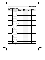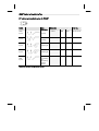
1
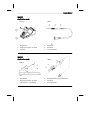
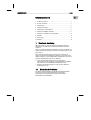
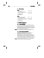
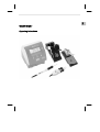
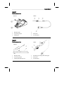
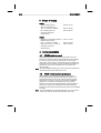
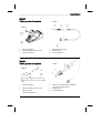
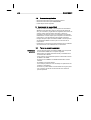
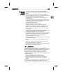
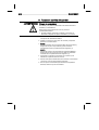
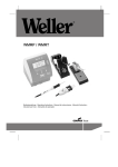
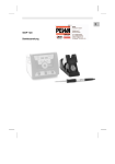
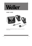
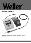
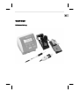
LV
EE
SL
SK
HU
PL
CZ
TR
GR
FI
DK
SV
NL
PT
ES
IT
Betriebsanleitung
LT
FR
WMRP/WMRT
EN
DE
WMRP/WMRT
WMRP
Geräteübersicht
WDH 50
WMRP
1.
Magnethalter
4.
Spitzengriff
2.
Reinigungsschwamm für Spitze
5.
Handstück
3.
Lötspitze
6.
Anschlussstecker
WMRT
Geräteübersicht
WMRT
WMRTH
1.
Magnethalter
4.
Entlötspitzenkartusche mit Griffschalen
2.
Reinigungsschwamm für Spitze
5.
Handstück
3.
Spitzenpaar für Löten/Entlöten
6.
Anschlussstecker
3 Lieferumfang .............................................................................. 6 4 Gerätebeschreibung .................................................................. 6 5 Inbetriebnahme des Gerätes ..................................................... 8 6 Wechsel der WMRP-Lötspitzen ................................................. 9 7 Wechseln von WMRT Löt-/Entlötspitzen ................................... 10 8 Zubehör ..................................................................................... 11 EN
FR
2 Zu Ihrer Sicherheit ..................................................................... 4 IT
1 Zu dieser Anleitung .................................................................... 3 ES
Inhaltsverzeichnis
DE
3-12
PT
WMRP/WMRT
Z Bewahren Sie diese Anleitung an einem für jeden Benutzer
zugänglichen Ort auf.
1.1
Einzuhaltende Richtlinien
Der Weller Lötkolben WMRP und die Mikroentlötspitzen WMRT
entsprechen der EG-Konformitätserklärung gemäß den
grundlegenden Sicherheitsanforderungen der Richtlinien
2004/108/EG und 2006/95/EG.
SV
DK
FI
GR
TR
CZ
PL
Z Lesen Sie bitte diese Anleitung und die zugehörigen
Sicherheitsrichtlinien sorgfältig vor Inbetriebnahme des WMRP
Lötkolbens bzw. der WMRT Mikroentlötpinzetten durch.
HU
Diese Anleitung enthält wichtige Informationen sowohl für die
sichere und korrekte Inbetriebnahme, Bedienung und Wartung des
WMRP Lötkolbens und der WMRT Mikroentlötpinzetten als auch zur
einfachen Fehlerbehebung durch den Bediener.
SK
Diese von Weller für überdurchschnittliche Leistung, Flexibilität und
Qualität entwickelten Produkte werden Ihren Anforderungen voll und
ganz gerecht.
SL
Wir danken Ihnen für das mit dem Kauf des Weller Lötkolbens
WMRP bzw. der Weller Mikroentlötpinzetten WMRT erwiesene
Vertrauen.
EE
Zu dieser Anleitung
LV
1
LT
10 Garantie ..................................................................................... 12 NL
9 Entsorgung ................................................................................ 11 4-12
WMRP/WMRT
1.2
Geltende Unterlagen
− Betriebsanleitung für Ihre Versorgungseinheit
− Betriebsanleitungen für WMRP/WMRT
− Beiliegendes Heft zur Sicherheit
2 Zu Ihrer Sicherheit
− Sowohl der Lötkolben WMRP als auch die Mikroentlötpinzetten
WMRT wurden dem neuesten Stand der Technik und
anerkannten Sicherheitsregeln und -bestimmungen entsprechend
hergestellt. Bei Nichtbeachtung der beiliegenden
Sicherheitsinformationen und aufgeführten Warnhinweise besteht
jedoch die Gefahr von Personen- und Sachschäden.
− Geben Sie den WMRP Lötkolben oder die WMRT
Mikroentlötpinzetten nur zusammen mit dieser Betriebsanleitung
weiter.
− Der Hersteller ist nicht haftbar für Schäden, die aus einer
unsachgemäßen Verwendung des Werkzeugs oder unerlaubten
Veränderungen am Gerät entstehen.
2.1
Allgemeine
Hinweise
Beachten Sie bitte Folgendes:
− Legen Sie den Lötkolben WMRP und die Mikroentlötpinzetten
WMRT immer in ihre ursprünglichen Halter.
− Entfernen Sie alle entzündbaren Objekte aus der Nähe des
heißen Lötwerkzeugs.
− Tragen Sie bei der Arbeit mit WMRP oder WMRT entsprechende
Schutzkleidung.
− Lassen Sie den heißen WMRP oder die WMRT nie
unbeaufsichtigt.
− Führen Sie keine Arbeiten an stromführenden Teilen aus.
− Tragen Sie bei Löt- oder Entlötanwendungen immer einen
Augenschutz.
− Es gibt keine Teile, die vom Benutzer gewartet werden können.
− Lesen und beachten Sie die Betriebsanleitung des jeweiligen
Gerätes.
Der Hersteller übernimmt keine Haftung für Schäden, die aus
unsachgemäßem, nicht dem in der Betriebsanleitung beschriebenen
Gebrauch oder unerlaubten Änderungen am Gerät resultieren.
EN
FR
IT
ES
PT
NL
SV
DK
FI
GR
TR
CZ
PL
HU
SK
Verwenden Sie den WMRP Lötkolben oder die WMRT
Mikroentlötpinzetten ausschließlich für den in der Betriebsanleitung
bezüglich Lösen, Verstauung und Ablage von elektronischen
Bauteilen angegebenen Zweck unter den hier beschriebenen
Bedingungen. Der bestimmungsgemäße Gebrauch des Lötkolbens
WMRP bzw. der Mikroentlötpinzette WMRT beinhaltet auch, dass
− Sie diese Anleitung beachten,
− Sie alle weiteren Begleitunterlagen beachten,
− Sie die nationalen Unfallverhütungsvorschriften am Einsatzort
beachten.
SL
Bestimmungsgemäßer Gebrauch
EE
2.2
LV
Umgang mit − Legen Sie heiße Löt- oder Entlötspitzen weder auf den
Löt-/Entlöt- Reinigungsschwamm (2) oder auf Kunststoffflächen noch lassen
spitzen Sie sie dort zurück.
− Benetzen Sie beim ersten Aufheizen des Kolbens die verzinnten
Löt-/Entlötspitzen mit Lot, wodurch lagerbedingte Oxidschichten
oder Unreinheiten von den Löt- bzw. Entlötspitzen entfernt
werden.
− Vergewissern Sie sich, dass bei Arbeitsunterbrechungen
zwischen Löten und Entlöten sowie vor der Lagerung des
Gerätes die Löt-/Entlötspitzen gut benetzt sind.
− Verwenden Sie keine aggressiven Flussmittel.
− Immer darauf achten, dass die Löt-/Entlötspitzen
ordnungsgemäß sitzen.
− Wählen Sie die niedrigstmögliche Arbeitstemperatur.
− Wählen Sie die längstmögliche Löt-/Entlötspitzenform für die
Anwendung: ca. so lang wie das Lötpad.
− Benetzen Sie die Löt-/Entlötspitzen gut, um effiziente
Wärmeübertragung zwischen Löt-/Entlötspitzen und Lötpunkt zu
gewährleisten.
− Schalten Sie das System ab, wenn Sie das Löt-/Entlötwerkzeug
nicht über längere Zeit verwenden möchten.
− Benetzen Sie die Spitzen vor Ablegen des Löt-/Entlötwerkzeugs
im Halter.
− Geben Sie das Lot direkt auf die Lötstelle, nicht auf die Löt-/
Entlötspitzen.
− Wenden Sie auf die Löt-/Entlötspitzen keine übermäßige Kraft
an.
− Halten Sie den Reinigungsschwamm (2) immer feucht.
Verwenden Sie nur destilliertes oder entionisiertes Wasser.
− Immer darauf achten, dass das Handstück (5) ordnungsgemäß
im Werkzeughalter (1) liegt.
DE
5-12
LT
WMRP/WMRT
6-12
WMRP/WMRT
3 Lieferumfang
WMRP:
− Lötkolben WMRP,
− Sicherheitsablage WDH 50
mit Stop+Go-Funktion für WMRP,
− RT 3 Lötspitze 40 W,
− Betriebsanleitung
− Sicherheitshinweise
T005 29 171 99
T005 15 156 99
T005 44 603 99
WMRT:
− Mikroentlötpinzetten WMRT,
T005 13 174 99
− Sicherheitsablage WMRTH
mit Stop+Go-Funktion für WMRT,
T005 15 146 99
− RTW 2 Spitzen-Set 0,7 x 0,4 mm, 45°, T005 44 652 99
− Betriebsanleitung
− Sicherheitshinweise
4 Gerätebeschreibung
4.1
Lötkolben WMRP
Der WMRP ist ein leistungsstarker 40 W-Feinlötkolben mit in der
Lötspitze integriertem Heizsystem. Dank eines Stecksystems kann
die Lötspitze werkzeuglos ausgewechselt werden. Die Temperatur
der Lötspitze wird schnell erreicht und genau kontrolliert. Dank eines
im Griff integrierten Sensors schaltet der Lötkolben automatisch ab,
wenn er in den Halter WDH 50 gelegt wird.
Hinweis
Der Lötkolben WMRP von Weller kann nur mit den Lötstationen
WD 1M, WD 2M, WD 3M, WR 3M eingesetzt werden.
4.2
Mikroentlötpinzetten WMRT
Die WMRT-Mikroentlötpinzetten von Weller wurden für das
Nachbearbeiten und die Reparatur von elektronischen
SMD-Präzisionsgeräten entwickelt. Das Spitzenset für
Löten/Entlöten kann schnell und problemlos ohne Werkzeug
ausgetauscht werden. Die Spitzen sind vorjustiert, eine zusätzliche
Ausrichtung ist nicht erforderlich. Die eingebauten Heizelemente
(2 x 40 W) garantieren, dass die Lötspitzentemperatur sehr schnell
erreicht und genau ausgeregelt wird. Die Entlötpinzetten werden bei
Ablage im Werkzeughalter WMRTH automatisch abgeschaltet.
Hinweis
Die WMRT-Mikroentlötpinzetten können nur mit den Lötstationen
WD 1M, WD 2M, WD 3M, WR 3M eingesetzt werden.
Temperaturbereich
100 °C – 450 °C (212 °F – 850 °F)
Werkzeugkabel
Silikonkautschuk, hitzebeständig
Heizelement
Heizdraht integriert in Spitzenkartusche
Sensortyp
Thermoelement integriert in
Spitzenkartusche
EN
Technische Daten
FR
4.3
DE
7-12
IT
WMRP/WMRT
Anschluss
5-polige St. verpolungssicher mit
Verriegelung
26 g incl. Spitzenkartusche ohne Kabel
Spitzentyp
RT-Baureihe
Gewicht
42 g incl. Spitzenkartusche ohne Kabel
Spitzentyp
RTW-Baureihe
GR
TR
CZ
6-polige St. verpolungssicher mit
Verriegelung
PL
Anschluss
HU
(ca.) 3 s (50°C auf 380°C)
(120°F auf 660 ºF)
SK
12 V
Aufheizzeit
SL
80 W (2 x 40 W)
Spannung (Heizung)
EE
Heizleistung
LV
WMRT
FI
DK
Gewicht
PT
(ca.) 3 s (50°C auf 380°C)
(120°F auf 660 ºF)
NL
12 V
Aufheizzeit
SV
40 W (55 W mit RT 11)
Spannung (Heizung)
LT
Heizleistung
ES
WMRP
8-12
WMRP/WMRT
5 Inbetriebnahme des Gerätes
WARNUNG! Verbrennungsgefahr
Der Lötkolben und die Entlötpinzetten werden beim
Löt-/Entlötvorgang sehr heiß.
Bei Berührung der Spitzen besteht Verbrennungsgefahr.
Z Berühren Sie nicht den heißen Lötkolben bzw. die
Entlötpinzetten und halten Sie entzündbare Objekte fern.
1. Den Lötkolben WMRP bzw. die Mikroentlötpinzetten WMRT
vorsichtig auspacken.
2. Den Stecker (6) an der Versorgungseinheit anschließen und
durch Drehen im Uhrzeigersinn verriegeln.
3. WMRP:
Den Lötkolben in der Sicherheitsablage WDH 50 ablegen und
darauf achten, dass der Lötkolbengriff (5) korrekt am
magnetischen Werkzeughalter (1) sitzt.
WMRT:
Die Pinzetten in die Sicherheitsablage WMRTH legen und darauf
achten, dass das Handstück (5) korrekt am magnetischen
Werkzeughalter (1) sitzt.
4. Überprüfen, ob die Hauptnetzspannung der Spannung auf dem
Typenschild entspricht.
5. Den Stationsstromschalter auf „On“ drehen und die erforderliche
Temperatur an der Steuerung einstellen.
6. Hat das Werkzeug die gewünschte Temperatur erreicht, die
Lötspitze mit Lot benetzen.
Auswechseln einer verbrauchten Spitze
1. Lötwerkzeug auf den Werkzeughalter legen.
Immer darauf achten, dass die Lötspitze ordnungsgemäß sitzt.
2. Stromschalter der Station auf „OFF“ drehen.
3. Drei Minuten warten, bis die Lötspitze kalt ist.
4. Lötkolben am weichen Griffbereich (4) anfassen und die
Lötspitze aus dem Werkzeug ziehen.
Einbau einer neuen Lötspitze:
VORSICHT! Gefahr einer Funktionsstörung
EN
FR
IT
ES
PT
Z Das Lötwerkzeug muss mindestens 3 Minuten in der
Sicherheitsablage (WDH 50) verbleiben, bis die Lötspitze
abgekühlt ist. Lötspitzen dürfen nur gewechselt werden, wenn
sie kalt sind.
NL
Der Lötkolben wird bei Löt- und Entlötvorgängen sehr heiß.
Bei Berührung der Lötspitze besteht Verbrennungsgefahr.
SV
WARNUNG! Verbrennungsgefahr
DK
6 Wechsel der WMRP-Lötspitzen
DE
9-12
FI
WMRP/WMRT
TR
CZ
PL
HU
SK
Bei unterschiedlichen Typen von Lötspitzen wird empfohlen, die
Spitze auf der Rückseite der Ablage WDH 50 zu lagern.
SL
Hinweis
EE
5. Lötkolben am weichen Griffbereich (4) anfassen und die Spitze in
das Lötwerkzeug schieben.
6. Stationsstromschalter auf „On“ drehen und die erforderliche
Temperatur an der Steuerung einstellen.
LV
Z Stellen Sie deshalb sicher, dass die Lötspitze in einem Zug
komplett bis zum Anschlag eingeschoben ist.
LT
Der Betrieb mit einer unvollständig eingesetzten Lötspitze kann
eine Funktionsstörung derselben verursachen.
GR
Die Lötspitze muss komplett eingesetzt werden.
10-12
WMRP/WMRT
7 Wechseln von WMRT Löt-/Entlötspitzen
WARNUNG! Verbrennungsgefahr
Die Pinzetten werden während des Entlötvorgangs sehr heiß.
Bei Berührung der Spitzen besteht Verbrennungsgefahr.
Z Die Pinzetten müssen mind. 3 Minuten in der
Sicherheitsablage WMRTH verbleiben, bis die Löt- bzw.
Entlötspitzen abgekühlt sind. Löt-/Entlötspitzen dürfen nur
ausgewechselt werden, wenn sie abgekühlt sind.
Auswechseln verbrauchter Spitzen
1. Pinzetten auf den Werkzeughalter legen.
Immer darauf achten, dass das Handstück (5) ordnungsgemäß
sitzt.
2. Stromschalter der Station auf „OFF“ drehen.
3. Drei Minuten warten, bis die Löt-/Entlötspitzen (3) abgekühlt sind.
Die Entlötspitzenkartusche (4) wird an der Vorderseite des
Handstücks (5) eingeführt. Der 5-polige Ministecker an der
Rückseite der Kartusche ist für die richtige Ausrichtung mit dem
Handstück gepolt.
4. Griffschalen fassen und auseinanderziehen, um die
Spitzenkartusche (4) aus dem Handstück zu lösen.
5. Griffschalen fassen und die Lötspitzen (3) aus der
Entlötspitzenkartusche (4) ziehen.
Einbau neuer Löt-/Entlötspitzen:
VORSICHT! Gefahr einer Funktionsstörung
Die Lötspitzen müssen komplett eingesteckt sein.
Der Betrieb mit einer unvollständig eingesetzten Löt-/Entlötspitze
kann eine Funktionsstörung der Kartusche verursachen.
Z Stellen Sie sicher, dass die Spitzen und die
Entlötspitzenkartusche in einem Zug komplett bis zum
Anschlag eingeschoben werden.
Hinweis
Oben auf der Kartusche (4) sind als Anzeiger für die richtige
Ausrichtung L (links) und R (rechts) aufgedruckt. Die Anzeiger
stimmen mit den aufgedruckten L- und R-Zeichen auf dem
Handstück (5) überein.
6. Griffschalenanfassen und die neuen Spitzen auf die
Löt-/Entlötkartusche (4) schieben.
7. Griffschalen anfassen und die Entlötspitzenkartusche (4) mit den
neuen Spitzen auf das Handstück (Pinzetten) (5) schieben.
8. Stationsstromschalter auf „On“ drehen und die erforderliche
Temperatur an der Steuerung einstellen.
11-12
Siehe Tabelle RT Lötspitzen für Lötkolben WMRP im Ende der
Anleitung und auf www.weller-tools.com
Ersatzteile und Zubehör für WMRP
RTW Löt-/Entlötspitzen für Mikroentlötpinzetten
WMRT
Siehe Tabelle RTW Löt-/Entlötspitzen für Mikroentlötpinzetten
WMRT am Ende dieser Anleitung und auf www.weller-tools.com
8.4
Ersatzteile und Zubehör für WMRT
Bestell-Nr.
Beschreibung
T005 13 174 99
Mikroentlötpinzetten WMRT
T005 15 146 99
Sicherheitsablage WMRTH
mit Stop + Go-Funktion
T005 44 652 99
RTW 2 Spitzen-Set 0,7 x 0,4 mm, 45°
T005 22 419 99
Schwamm (70 x 55 x 16 mm)
9 Entsorgung
Entsorgen Sie ausgetauschte Geräteteile, Filter oder alte Geräte
gemäß den Vorschriften Ihres Landes.
PT
NL
SV
DK
8.3
FI
Schwamm (70 x 55 x 16 mm)
GR
T005 22 419 99
TR
Bügel, der seitlich an der Ablage
angebracht werden kann und
zwei RT-Spitzen hält
CZ
RT 3 Lötspitze 40 W
T005 87 518 16
PL
T005 44 603 99
HU
Sicherheitsablage WDH 50
mit Stop + Go-Funktion
SK
Lötkolben WMRP für RT Lötspitzen
T005 15 156 99
SL
T005 29 171 99
ES
Beschreibung
EE
Bestell-Nr.
LV
8.2
FR
RT Lötspitzen für den Lötkolben WMRP
LT
8.1
IT
8 Zubehör
EN
DE
WMRP/WMRT
12-12
WMRP/WMRT
10 Garantie
Die Mängelansprüche des Käufers verjähren nach einem Jahr ab
Ablieferung an ihn. Dies gilt nicht für Rückgriffsansprüche des
Käufers nach §§ 478, 479 BGB.
Aus einer von uns abgegebenen Garantie haften wir nur bei
Ansprüchen, wenn die Beschaffenheits- oder Haltbarkeitsgarantie
von uns schriftlich und unter Verwendung des Begriffs „Garantie“
abgegeben worden ist.
Technische Änderungen vorbehalten!
Die aktualisierten Betriebsanleitungen finden Sie unter
www.weller-tools.com.
LV
EE
SL
SK
HU
PL
CZ
TR
GR
FI
DK
SV
NL
PT
ES
IT
Operating Instructions
LT
FR
WMRP/WMRT
EN
DE
WMRP/WMRT
WMRP
Device overview
WDH 50
WMRP
1.
Magnetic holder
4.
Tip grip
2.
Tip cleaning sponge
5.
Hand piece
3.
Soldering tip
6.
Connector/plug
WMRT
Device overview
WMRT
WMRTH
1.
Magnetic holder
4.
Desoldering tip cartridge with molded grips
2.
Tip cleaning sponge
5.
Hand piece
3.
Soldering/desoldering tip pair
6.
Connector/plug
3 Scope of supply ......................................................................... 6 4 Device description ..................................................................... 6 5 Commissioning the device ......................................................... 8 6 Changing WMRP soldering tips ................................................. 9 7 Changing WMRT soldering/desoldering tips ............................. 10 8 Accessories ............................................................................... 11 EN
FR
2 For your safety ........................................................................... 4 IT
1 About these instructions ............................................................ 3 ES
Contents
DE
3-12
PT
WMRP/WMRT
These instructions contain important information which will help you
to start up, operate and service the WMRP soldering pencil and
WMRT micro desoldering tweezers safely and correctly, as well as
to eliminate simple faults/malfunctions yourself.
Z Please read these instructions carefully and the attached safety
guidelines before you put the WMRP soldering pencil or WMRT
micro desoldering tweezers into operation.
Z Keep these instructions in a place that is accessible to all users.
SV
DK
FI
EE
SL
SK
HU
Directives taken into consideration
The Weller WMRP soldering pencil and WMRT micro desoldering
tweezers correspond to the EC Declaration of Conformity in
accordance with the basic safety requirements of Directives
2004/108/EC and 2006/95/EC.
LV
1.1
GR
These products meet or exceed the requirements established by
Weller for superior performance, versatility and quality.
TR
Thank you for placing your trust in our company by purchasing the
Weller WMRP soldering pencil or the Weller WMRT micro
desoldering tweezers.
CZ
About these instructions
LT
1
PL
10 Warranty .................................................................................... 12 NL
9 Disposal ..................................................................................... 11 4-12
WMRP/WMRT
1.2
Applicable documents
− Operating instructions for your power unit
− WMRP/WMRT operating instructions
− Accompanying booklet on safety
2 For your safety
− The WMRP soldering pencil and WMRT micro desoldering
tweezers have been manufactured in accordance with state-ofthe-art technology and recognized safety rules and regulations.
There is nevertheless the risk of personal injury and damage to
property if you fail to observe the safety information set out in the
enclosed booklet accompanying these operating instructions and
the warnings given therein.
− Always pass on the WMRP soldering pencil or WMRT micro
desoldering tweezers on to third parties along with these operating
instructions.
− The manufacturer shall not be liable for damage resulting from
misuse of the tool or unauthorized alterations
− State of California warning:
When used for soldering and similar applications, this product
produces chemicals known to the State of California to cause
cancer and birth defects or other reproductive harm.
2.1
General
instructions
Please observe the following:
− Always place the WMRP soldering pencil and WMRT micro
desoldering tweezers in their original holders.
− Remove all flammable objects from the vicinity of the hot
soldering tool.
− Always wear suitable protective clothing when using the WMRP
or WMRT.
− Never leave the hot WMRP or WMRT unattended.
− Do not carry out work on live parts
− Always wear eye protection when working with soldering and
desoldering applications.
− There are no parts that can be serviced by the user.
− Read and observe the operating instructions of the applicable
power unit.
The manufacturer accepts no liability for damages resulting from
failure to use the device in compliance with these operating
instructions or unauthorized modifications to the device.
EN
FR
IT
ES
PT
NL
SV
DK
FI
GR
TR
CZ
PL
HU
SK
Use the WMRP soldering pencil or WMRT micro desoldering
tweezers exclusively for the purpose indicated in the operating
instructions of releasing, accommodating and setting down chip
components under the conditions specified here. Intended use of the
WMRP soldering pencil or WMRT micro desoldering tweezers also
includes that
− you read and follow these instructions,
− you read and follow all additional accompanying documents,
− you observe the national accident-prevention regulations
applicable at the location where the device is used.
SL
Intended use
EE
2.2
LV
Handling − Do not place or leave the hot soldering/desoldering tips on the
soldering/ cleaning sponge (2) or on plastic surfaces.
desoldering − Coat the tin-plated soldering/desoldering tips with solder when
tips heating the iron for the first time, as this will remove any oxide
films or impurities from the soldering/desoldering tips that have
accumulated during storage.
− During breaks between soldering/desoldering and before storing
the tool, ensure that the soldering/desoldering tips are wellcoated.
− Do not use aggressive fluxing agents.
− Always make sure that the soldering/desoldering tips are seated
correctly.
− Select the lowest possible working temperature.
− Select the largest possible soldering/desoldering tips shape for
the application: approx. as large as the soldering pad.
− Coat the soldering/desoldering tips well to ensure efficient heat
transfer between the soldering/desoldering tips and the soldering
point.
− Switch off the system if you do not intend to use the
soldering/desoldering tool for longer periods.
− Coat the tips before placing the soldering/desoldering tool in the
holder.
− Apply the solder directly at the soldering point, not on the
soldering/desoldering tips.
− Do not subject the soldering/desoldering tips to physical forces.
− Always keep the cleaning sponge (2) damp. Use only distilled or
de-ionized water.
− Always ensure that the hand piece (5) is properly seated in the
tool holder (1).
DE
5-12
LT
WMRP/WMRT
6-12
WMRP/WMRT
3 Scope of supply
WMRP:
− WMRP soldering pencil,
− WDH 50 safety rest with
stop + go function for WMRP
− RT 3 soldering tip 40 W,
− Operating instructions
− Safety booklet
T005 29 171 99
T005 15 156 99
T005 44 603 99
WMRT:
− WMRT micro desoldering tweezers, T005 13 174 99
− WMRTH safty rest with
stop + go function for WMRT,
T005 15 146 99
− RTW 2 Tip Set 0,7 x 0,4 mm, 45°,
T005 44 652 99
− Operating instructions
− Safety booklet
4 Device description
4.1
WMRP soldering pencil
The WMRP soldering pencil is a extremely powerful 40 W fine
soldering iron with the heating system integrated into the soldering
tip. Due to a plug-in system, the soldering tip can be changed
without tools. The soldering tip temperature is reached rapidly and
controlled precisely. Thanks to a sensor installed in the handle, the
soldering iron is shut off automatically when it is placed in the
WDH 50 holder.
Note
The Weller WMRP soldering pencil may only be used with WD 1M,
WD 2M, WD 3M, WR 3M series power units.
4.2
WMRT micro desoldering tweezers
Weller WMRT micro desoldering tweezers are designed for
reworking and repairing precision SMT electronic devices. The
soldering/desoldering tip set can be quickly and easily changed
without the use of tools. The tips are pre-aligned and additional
alignment is not required. The integrated (2 x 40 W) heating
elements ensure that the soldering/desoldering tip temperature is
reached very quickly and controlled precisely. The desoldering
tweezers are switched off automatically when placed in the WMRTH
tool holder.
Note
The Weller WMRT micro desoldering tweezers may only be used
with WD 1M, WD 2M, WD 3M, WR 3M series power units.
100°C – 450°C (212°F – 850°F)
Tool cable
Silicone rubber, heat resistant
Heating element
Heating wire integrated in tip cartridge
Sensor
Thermocouple integrated in tip cartridge
40 W (55 W with RT 11)
Heating voltage
12 VAC
Heat-up time
(ca.) 3 s (50°C from ambient to 380ºC
(120°F from ambient to 750ºF)
Connector
Polarized, 5-pin locking
Tool weight
26 g incl. tip cartridge without cord
Tip type
RT series
PT
Heating output
NL
WMRP
ES
IT
Temperature range
EN
Technical data
SV
4.3
DE
7-12
FR
WMRP/WMRT
FI
GR
RTW series
TR
Tip type
CZ
42 g incl. tip cartridge without cord
PL
Polarized, 6-pin locking
Tool weight
HU
Connector
SK
(ca.) 3 s (50°C from ambient
to 380ºC (120°F from ambient
to 750ºF)
SL
Heat-up time
EE
12 VAC
LV
80 W (2 x 40 W)
Heating voltage
LT
Heating output
DK
WMRT
8-12
WMRP/WMRT
5 Commissioning the device
WARNING! Risk of burns
The soldering iron and desoldering tweezers become hot during
soldering and desoldering.
There is a risk of burns from touching the soldering/desoldering
tips.
Z Keep the hot soldering iron and desoldering tweezers well
away from flammable objects and do not touch.
1. Carefully unpack the WMRP soldering pencil or WMRT micro
desoldering tweezers.
2. Insert the connector (6) into the power supply socket and lock it
by turning clockwise.
3. WMRP:
Place the soldering iron in the safety WDH 50 tool stand and
ensure that the soldering iron grip (5) is correctly seated against
the magnetic tool holder (1).
WMRT:
Place the tweezers in the WMRTH safety tool stand and ensure
that the hand piece (5) is correctly seated against the magnetic
tool holder (1).
4. Check whether the main supply voltage matches the voltage
indicated on the rating plate.
5. Turn the station power switch to “On” and set the required
temperature on the control.
6. Once the tool has reached the desired temperature, tin the
soldering tip with solder.
Operation with a soldering tip that is not completely inserted can
cause the tip to malfunction.
Z Ensure that the soldering tip is inserted completely up to the
stop in a single motion.
5. Grasp the soldering iron on the soft grip area (4) and push the
new tip on to the soldering tool.
6. Turn the station power switch to “On” and set the required
temperature on the control.
Note
When using several types of soldering tips, it is recommended to
store the tip on the back of the tool stand WDH 50.
EN
FR
IT
ES
PT
NL
SV
DK
FI
GR
The soldering tip must be completely inserted.
TR
CAUTION! Risk of malfunction
CZ
Installing a new soldering tip:
PL
1. Place the soldering tool on the tool holder.
Always ensure that the soldering tip is properly seated.
2. Turn the station power switch to “OFF”.
3. Wait 3 min. until the soldering tip is cold.
4. Grasp the soldering iron on the soft grip area (4) and pull the
soldering tip from the tool.
HU
Removing old tip
SK
Z The soldering tool must stand at least 3 min. in the safety tool
holder (WDH 50) before the soldering tip is cold. Soldering tips
must only be changed when cool.
SL
The soldering iron becomes hot during soldering and desoldering.
There is a risk of burns from touching the soldering tip.
EE
WARNING! Risk of burns
LV
6 Changing WMRP soldering tips
DE
9-12
LT
WMRP/WMRT
10-12
WMRP/WMRT
7 Changing WMRT soldering/desoldering
tips
WARNING! Risk of burns
The tweezers become hot during soldering and desoldering.
There is a risk of burns from touching the soldering/desoldering
tips.
Z The tweezers must stand at least 3 min. in the safety tool
holder (WMRTH) before the soldering/desoldering tips are
cold. Soldering/desoldering tips may only be changed when
cool.
Removing old tips
1. Place the tweezers on the tool holder.
Always ensure that the hand piece (5) is properly seated.
2. Turn the station power switch to “OFF”.
3. Wait 3 min. until the soldering/desoldering tips (3) are cold.
The desoldering tip cartridge (4) is inserted into the front of the hand
piece (5). The 5-pin mini-plug on the back of the tip cartridge is
polarized for correct alignment with the hand piece.
4. Grasp the molded grips and pull outward to release the tip
cartridge (4) from the hand piece.
5. Grasp the molded grips and pull the soldering/desoldering tips (3)
from the desoldering tip cartridge (4).
Installing new soldering/desoldering tips:
CAUTION! Risk of malfunction
The soldering/desoldering tips must be completely inserted.
Operation with a soldering/desoldering tip that is not completely
inserted can cause the tip cartridge to malfunction.
Z Ensure that the soldering/desoldering tips and the desoldering
tip cartridge are inserted completely against the stop in a
single motion.
Note
The top of the tip cartridge (4) is printed with L (left) and R (right) as
indicators for proper orientation. The indicators align with the L and
R indicators printed on the hand piece (5).
6. Grasp the molded grips and push the new tips on to the
soldering/desoldering tip cartridge (4).
7. Grasp the molded grips and push the desoldering tip cartridge (4)
with the new tips on to the hand piece (tweezers) (5).
8. Turn the station power switch to “On” and set the required
temperature on the control.
T005 22 419 99
Sponge (70 x 55 x 16 mm)
8.3
RTW soldering/desoldering tips for WMRT
micro desoldering tweezers
See the table RTW soldering/desoldering tips for WMRT micro
desoldering tweezers in the section in the back and at
www.weller-tools.com
8.4
WMRT replacement parts and accessories
Order no.
Description
T005 13 174 99
WMRT micro desoldering tweezers
T005 15 146 99
WMRTH safety rest with stop + go function
T005 44 652 99
RTW 2 tip set 0.7 x 0.4 mm, 45°
T005 22 419 99
Sponge (70 x 55 x 16 mm)
9 Disposal
Dispose of replaced equipment parts, filters, or old devices in
accordance with the rules and regulations applicable in your country.
EN
FR
IT
ES
PT
Bracket that can be plugged sideways into
the stand and hold two RT tips
NL
T005 87 518 16
SV
RT 3 soldering tip 40 W
DK
WDH 50 safety rest with stop + go function
T005 44 603 99
FI
WMRP soldering pencil for RT soldering tips
T005 15 156 99
GR
T005 29 171 99
TR
Description
CZ
Order no.
PL
WMRP replacement parts and accessories
HU
8.2
SK
See the table RT soldering tips for WMRP soldering pencil in the
section in the back and at www.weller-tools.com
SL
RT soldering tips for WMRP soldering pencil
EE
8.1
LV
8 Accessories
DE
11-12
LT
WMRP/WMRT
12-12
WMRP/WMRT
10 Warranty
Claims by the buyer for physical defects are time-barred after a
period of one year from delivery to the buyer. This does not apply to
claims by the buyer for indemnification in accordance with §§ 478,
479 BGB (German Federal Law Gazette).
We shall only be liable for claims arising from a warranty furnished
by us if the quality or durability warranty has been furnished by use
in writing and using the term "Warranty“.
In addition, for the USA and Canada:
Weller Tools warrants to the original purchaser and any subsequent
owner (“Buyer”) that Weller soldering and desoldering products will
be free from defects in material and workmanship for a period of one
year from date of purchase, provided that no warranty is made with
respect to products which have been altered, subjected to abuse or
improperly used, installed or repaired. Use of non-Weller Tools
components will void this warranty if a non-Weller Tools component
is defective (or is the source of the defect). Weller Tools will repair or
replace products found to be defective not caused by a part,
component or accessory manufactured by another company, during
the warranty period. Contact Weller Tools with dated proof of
purchase and return to Apex Tool Group, LLC. 14600 York Rd. Suite
A, Sparks, MD 21152. All costs of transportation and reinstallation
shall be borne by the Buyer.
IN NO EVENT SHALL WELLER TOOLS BE LIABLE FOR
INCIDENTAL OR CONSEQUENTIAL DAMAGES. WELLER TOOLS
LIABILITY FOR ANY CLAIMS ARISING OUT OF THIS WARRANTY
SHALL NOT EXCEED THE PURCHASE PRICE OF THE
PRODUCT.
THE PERIOD OF ALL IMPLIED WARRANTIES APPLICABLE TO
THIS PRODUCT INCLUDING ANY IMPLIED WARRANTY OF
MERCHANTABILITY OR FITNESS, OR FITNESS FOR A
PARTICULAR PURPOSE IS LIMITED TO 12 MONTHS FROM THE
DATE OF PURCHASE BY THE USER.
Some states do not allow the exclusion or limitation of incidental or
consequential damages, so the above limitation or exclusion may
not apply to you. Some states do not allow limitation on how long an
implied warranty lasts, so the above limitation may not apply to you.
This warranty gives you specific legal rights, and you may also have
other rights, which vary from state to state.
Subject to technical alterations and amendments!
Updated operating instructions are available for download at
www.weller-tools.com.
LV
EE
SL
SK
HU
PL
CZ
TR
GR
FI
DK
SV
NL
PT
ES
IT
Manual de instrucciones
LT
ES
WMRP/WMRT
EN
DE
WMRP/WMRT
WMRP
Visión general del aparato
WMRP
WDH 50
1.
Soporte magnético
4.
Empuñadura de la punta
2.
Esponja limpiadora para la punta
5.
Pieza de mano
3.
Punta de soldadura
6.
Conector/enchufe
WMRT
Visión general del aparato
WMRT
WMRTH
1.
Soporte magnético
4.
Cartucho con empuñaduras moldeadas
para puntas de desoldadura
2.
Esponja limpiadora para la punta
5.
Pieza de mano
3.
Par de puntas de
soldadura/desoldadura
6.
Conector/enchufe
2 Acerca de la seguridad .............................................................. 4 3 Volumen de suministro .............................................................. 6 4 Descripción del aparato ............................................................. 6 5 Puesta en servicio del aparato .................................................. 8 EN
1 Acerca de estas instrucciones ................................................... 3 ES
Índice
DE
3-12
IT
WMRP/WMRT
7 Cambio de las puntas de soldadura/desoldadura WMRT ......... 10 ES
6 Cambio de las puntas de soldadura WMRP .............................. 9 9 Gestión de residuos ................................................................... 11 PT
8 Accesorios ................................................................................. 11 1.1
Directivas a tener en cuenta
El lápiz de soldadura WMRP y las micropinzas de desoldadura
WMRT se ajustan a la declaración de conformidad CE de acuerdo
con los requisitos de seguridad básicos de las Directivas
2004/108/CE y 2006/95/CE.
SV
DK
FI
GR
TR
CZ
PL
HU
Mantenga estas instrucciones en un lugar accesible para todos
los usuarios.
SK
Lea estas instrucciones detenidamente y también las directrices
de seguridad adjuntas antes de comenzar con el manejo del
lápiz de soldadura WMRP o de las micropinzas de desoldadura
WMRT.
SL
Estas instrucciones contienen información importante que le
ayudará a montar, manejar y llevar a cabo el mantenimiento del
lápiz de soldadura WMRP y las micropinzas de desoldadura WMRT
de un modo seguro y correcto, así como a eliminar los sencillos
fallos/averías por usted mismo.
EE
Estos productos cumplen o superan los requisitos establecidos por
Weller en cuanto a la excelencia en rendimiento, versatilidad y
calidad.
LV
Gracias por depositar su confianza en nuestra compañía con la
compra de un lápiz de soldadura WMRP de Weller o unas
micropinzas de desoldadura WMRT de Weller.
LT
1 Acerca de estas instrucciones
NL
10 Garantía ..................................................................................... 12 4-12
WMRP/WMRT
1.2
Documentos aplicables
− Manual de instrucciones para la unidad de potencia
− Manual de instrucciones para WMRP/WMRT
− Folleto adjunto sobre seguridad
2 Acerca de la seguridad
− El lápiz de soldadura WMRP y las micropinzas de desoldadura
WMRT han sido fabricados según la tecnología del estado del
arte y las normativas y reglamentos de seguridad reconocidos. No
obstante, existe riesgo de daños personales y daños a la
propiedad si se hace caso omiso a la información de seguridad
establecida en el folleto adjunto que acompaña a este manual de
instrucciones y a las advertencias mencionadas al respecto.
− Entregar siempre el lápiz de soldadura WMRP o las micropinzas
de desoldadura WMRT a terceros junto con este manual de
instrucciones.
− El fabricante no asumirá ningún daño resultante del uso indebido
de la herramienta ni de modificaciones no autorizadas.
2.1
Instrucciones
generales
Tener en cuenta lo siguiente:
− Colocar siempre el lápiz de soldadura WMRP y las micropinzas
de desoldadura WMRT en sus soportes originales.
− Retirar todos los objetos inflamables de las proximidades de la
herramienta de soldadura.
− Llevar siempre una indumentaria protectora adecuada al utilizar
el WMRP o las WMRT.
− No dejar nunca el WMRP o las WMRT desatendidos si están
calientes.
− No trabajar en las piezas activas.
− Llevar siempre protección ocular al trabajar con aplicaciones de
soldadura y desoldadura.
− El usuario no puede realizar el mantenimiento de ninguna pieza.
− Leer y observar el manual de instrucciones de la unidad de
potencia aplicable.
El fabricante no asumirá ningún daño resultante del uso incorrecto
de este aparato en cumplimiento con el presente manual de
instrucciones o de las modificaciones no autorizadas en el aparato.
EN
ES
IT
ES
PT
NL
SV
DK
FI
GR
TR
CZ
PL
HU
SK
Emplear el lápiz de soldadura WMRP o las micropinzas de
desoldadura WMRT exclusivamente para el propósito indicado en el
manual de instrucciones en lo referente a liberación, alojamiento y
fijación de los componentes de chip bajo las condiciones
especifiicadas aquí. Dentro del uso previsto para el lápiz de
soldadura WMRP o las micropinzas de desoldadura WMRT también
se incluye lo siguiente:
− Lectura y seguimiento de estas instrucciones
− Lectura y seguimiento de los documentos adjuntos
− Observación del reglamento nacional sobre prevención de
accidentes aplicable en la ubicación en la que se utilice el
aparato.
SL
Uso previsto
EE
2.2
LV
Manejo de las − No colocar ni dejar las puntas de soldadura/desoldadura
puntas de calientes sobre la esponja limpiadora (2) ni sobre superficies de
soldadura/ plástico.
desoldadura − Recubrir las puntas de soldadura/desoldadura estañadas al
calentar el soldador por primera vez, así se eliminarán todas las
películas de óxido o impurezas de las puntas de
soldadura/desoldadura que se hayan acumulado durante el
almacenamiento.
− Durante las interrupciones de la soldadura/desoldadura y antes
de almacenar la herramienta, asegurarse de que las puntas de
soldadura/desoldadura estén bien recubiertas.
− No utilizar fundentes agresivos.
− Asegurarse siempre de que las puntas de
soldadura/desoldadura estén colocadas correctamente.
− Seleccionar una temperatura de trabajo lo más baja posible.
− Seleccionar unas puntas de soldadura/desoldadura lo más
largas posibles para la aplicación: aprox. de la longitud de la
placa de soldar.
− Recubrir bien las puntas de soldadura/desoldadura para
asegurarse una transferencia de calor eficiente entre las puntas
de soldadura/desoldadura y el punto de soldadura.
− Desconectar el sistema si no está previsto utilizar la herramienta
de soldadura/desoldadura durante largos periodos de tiempo.
− Recubrir las puntas antes de colocar la herramienta de
soldadura/desoldadura en el soporte.
− Soldar directamente en el punto de soldadura, no en las puntas
de soldadura/desoldadura.
− No someter las puntas de soldadura/desoldadura a fuerzas
físicas.
− Mantener la esponja limpiadora (2) siempre húmeda. Utilizar
solamente agua destilada o desionizada.
− Asegurarse siempre de que la pieza de mano (5) esté colocada
correctamente en el portaherramienta (1).
DE
5-12
LT
WMRP/WMRT
6-12
WMRP/WMRT
3 Volumen de suministro
WMRP:
− Lápiz de soldadura WMRP,
− Soporte de seguridad WDH 50
con función intermitente para WMRP,
− Punta de soldadura RT 3 de 40 W,
− Manual de instrucciones
− Folleto sobre seguridad
T005 29 171 99
T005 15 156 99
T005 44 603 99
WMRT:
− Micropinzas de desoldadura WMRT,
− Soporte de seguridad WMRTH
con función intermitente para WMRT,
− Juego de 2 puntas RTW de 0,7 x 0,4 mm, 45°,
− Manual de instrucciones
− Folleto sobre seguridad
T005 13 174 99
T005 15 146 99
T005 44 652 99
4 Descripción del aparato
4.1
Lápiz de soldadura WMRP
El lápiz de soldadura WMRP es un soldador fino de 40 W
extremadamente potente con un sistema de calentamiento integrado
en la punta de soldadura. Debido al sistema de conexión, la punta
de soldadura puede cambiarse sin herramientas. La temperatura de
la punta de soldadura se alcanza rápidamente y se puede controlar
con precisión. Gracias al sensor instalado en el mango, el soldador
se desconecta automáticamente al ser colocado en el soporte
WDH 50.
Nota
El lápiz de soldadura WMRP puede utilizarse únicamente con
unidades de potencia de las series WD 1M, WD 2M, WD 3M,
WR 3M.
4.2
Micropinzas de desoldadura WMRT
Las micropinzas de desoldadura WMRT de Weller están diseñadas
para conseguir una precisión durante la revisión y reparación de
aparatos electrónicos SMT. El juego de puntas de soldadura/
desoldadura puede cambiarse de forma rápida y sencilla sin
necesidad de utilizar ninguna herramienta. Las puntas están
prealineadas, con lo que no se necesita una alineación adicional.
Los elementos calefactores (2 x 40 W) integrados aseguran que la
temperatura de la punta de soldadura/desoldadura se alcance
rápidamente y pueda controlarse de un modo preciso. Las pinzas de
desoldadura se desconectan automáticamente cuando se colocan
en el portaherramienta WMRTH.
Nota
Las pinzas micropinzas de desoldadura WMRT de Weller pueden
utilizarse únicamente con unidades de potencia de las series
WD 1M, WD 2M, WD 3M, WR 3M.
Cable de la
herramienta
Caucho de silicona, resistente al fuego
Elemento calefactor
Alambre de calefacción integrado en el
cartucho para puntas
Elemento térmico integrado en el
Tiempo de
calentamiento
(aprox.)3 s (50°C a 380°C)
(120°F a 660°F)
Conector
Conector de 6 polos con protección
contra polaridad inversa y mecanismo de
bloqueo
Peso de la
herramienta
26 g incluido cartucho para puntas sin
cable
Tipo de punta
Serie RT
SV
12 V
DK
Tensión de
calentamiento
FI
40 W (55 W con RT 11)
Tiempo de
calentamiento
(aprox.)3 s (50°C a 380°C)
(120°F a 660°F)
Conector
Conector de 7 polos con protección
contra polaridad inversa y mecanismo de
bloqueo
Peso de la
herramienta
42 g incluido cartucho para puntas sin
Tipo de punta
Serie RTW
cable
PL
12 V
HU
Tensión de
calentamiento
SK
80 W (2 x 40 W)
SL
Potencia de
calentamiento
EE
WMRT
CZ
TR
Potencia de
calentamiento
GR
WMRP
NL
PT
cartucho para puntas
LV
Sensor
EN
100 °C – 450 °C (212 °F – 850 °F)
ES
Rango de
temperaturas
IT
Datos técnicos
LT
4.3
DE
7-12
ES
WMRP/WMRT
8-12
WMRP/WMRT
5 Puesta en servicio del aparato
¡ADVERTENCIA! Riesgo de quemaduras
El soldador y las pinzas de desoldadura se calienta durante la
soldadura y la desoldadura.
Existe riesgo de quemaduras al tocar las puntas de
soldadura/desoldadura.
Si están calientes, mantener el soldador y las pinzas de
desoldadura alejadas de objetos inflamables y no tocarlos.
1. Desembalar con cuidado el lápiz de soldadura WMRP o las
micropinzas de desoldadura WMRT.
2. Insertar el conector (6) en la toma de corriente y bloquearlo
girándolo en sentido horario.
3. WMRP:
Colocar el soldador en la herramienta WDH 50 de seguridad y
asegurarse de que su empuñadura (5) esté colocada
correctamente sobre el portaherramienta magnético (1).
WMRT:
Colocar las pinzas en la herramienta de seguridad WMRTH y
asegurarse de que la pieza de mano (5) esté correctamente
colocada sobre el portaherramienta magnético (1).
4. Comprobar si la tensión de suministro es la misma que la
indicada en la placa de datos de servicio.
5. Girar el interruptor de alimentación de la estación a “Conectado”
y ajustar en el control la temperatura requerida.
6. Una vez que la herramienta haya alcanzado la temperatura
deseada, estañar la punta de soldadura.
Instalación de una punta de soldadura nueva:
¡PRECAUCIÓN! Riesgo de avería
La punta de soldadura debe insertarse completamente.
Si se utiliza la herramienta con una punta de soldadura que no
esté insertada por completo, se puede provocar un mal
funcionamiento de la punta.
Asegurarse de que la punta de soldadura esté insertada
completamente hasta llegar al tope cuando se realiza un
movimiento sencillo.
5. Agarrar el soldador por la zona suave de la empuñadura (4) y
empujar la punta nueva en la herramienta de soldadura.
6. Girar el interruptor de alimentación de la estación a “Conectado”
y ajustar en el control la temperatura requerida.
Nota
Si se utilizan varios tipos de punta de soldadura, se recomienda
guardar la punta en la parte trasera del portaherramienta WDH 50.
EN
ES
IT
ES
PT
NL
SV
DK
FI
4. Agarrar el soldador por la zona suave de la empuñadura (4) y
sacar la punta de soldadura de la herramienta.
GR
3. Esperar 3 min hasta que la punta de soldadura se enfríe.
TR
2. Girar el interruptor de alimentación de la estación a
“Desconectado”.
CZ
1. Colocar la herramienta de soldadura en el portaherramienta.
Asegúrese siempre de que la punta de soldadura está encajada
correctamente.
PL
Extracción de la punta antigua
HU
La herramienta de soldadura debe permanecer en el
portaherramienta de seguridad (WDH 50) por lo menos
durante 3 min para que la punta de soldadura se enfríe. Las
puntas de soldadura solo se deben cambiar cuando estén
frías.
SK
El soldador se calienta durante la soldadura y desoldadura.
Existe riesgo de quemaduras al tocar la punta de soldadura.
SL
¡ADVERTENCIA! Riesgo de quemaduras
EE
Cambio de las puntas de soldadura
WMRP
LV
6
DE
9-12
LT
WMRP/WMRT
10-12
WMRP/WMRT
7
Cambio de las puntas de
soldadura/desoldadura WMRT
¡ADVERTENCIA! Riesgo de quemaduras
Las pinzas se calientan durante la soldadura y desoldadura.
Existe riesgo de quemaduras al tocar las puntas de
soldadura/desoldadura.
Las pinzas deben permanecer en el portaherramienta de
seguridad (WMRTH) por lo menos durante 3 min para que las
puntas de soldadura/desoldadura se enfríen. Únicamente
pueden cambiarse las puntas de soldadura/desoldadura
cuando estén frías.
Extracción de las puntas antiguas
1. Colocar las pinzas en el portaherramienta.
Asegurarse siempre de que la pieza de mano (5) esté colocada
correctamente.
2. Girar el interruptor de alimentación de la estación a
“Desconectado”.
3. Esperar 3 min hasta que las puntas de soldadura/
desoldadura (3) estén frías.
El cartucho (4) para puntas de desoldadura está insertado en la
parte frontal de la pieza de mano (5). El minienchufe de 5 clavijas de
la parte trasera del cartucho está polarizado para alinearse
correctamente con la pieza de mano.
4. Agarrar las empuñaduras moldeadas y tirar hacia afuera para
liberar el cartucho (4) para puntas de la pieza de mano.
5. Agarrar las empuñaduras moldeadas y extraer las puntas de
soldadura/desoldadura (3) del cartucho (4) para puntas de
desoldadura.
Instalación de unas puntas de soldadura/desoldadura nuevas:
¡PRECAUCIÓN! Riesgo de avería
Las puntas de soldadura/desoldadura deben insertarse
completamente.
Si se utiliza una punta de soldadura/desoldadura que no esté
insertada por completo, puede causar una avería en el cartucho
para puntas.
Asegurarse de que las puntas de soldadura/desoldadura y el
cartucho para puntas de desoldadura estén insertados
completamente para evitar la parada en un movimiento
sencillo.
Nota
En la parte superior del cartucho (4) para puntas están impresos
los indicadores L (izquierda) y R (derecha) para su correcta
orientación. Estos indicadores están alineados con los indicadores
L y R impresos en la pieza de mano (5).
6. Agarrar las empuñaduras moldeadas y presionar las puntas
nuevas para introducirlas en el cartucho (4) para puntas de
soldadura/desoldadura.
Brazo que puede insertarse en los laterales
del soporte para sujetar las dos puntas RT
T005 22 419 99
Esponja (70 x 55 x 16 mm)
8.3
Puntas de soldadura/desoldadura RTW para
micropinzas de desoldadura WMRT
Ver la tabla de puntas de soldadura/desoldadura RTW para
micropinzas de desoldadura WMRT en la sección al reverso y en
www.weller-tools.com
8.4
Piezas de repuesto y accesorios WMRT
N.º pedido
Descripción
T005 13 174 99
Micropinzas de desoldadura WMRT
T005 15 146 99
Soporte de seguridad WMRTH con función
intermitente
T005 44 652 99
Juego de 2 puntas RTW de 0,7 x 0,4 mm,
45°
T005 22 419 99
Esponja (70 x 55 x 16 mm)
9 Gestión de residuos
Eliminar las piezas sustituidas del equipo, filtros u otros aparatos
antiguos según las normas y regulaciones aplicables en el país
correspondiente.
ES
PT
NL
T005 87 518 16
SV
Punta de soldadura RT 3 de 40 W
DK
T005 44 603 99
FI
Soporte de seguridad WDH 50
con función intermitente
GR
T005 15 156 99
TR
Lápiz de soldadura WMRP para puntas de
soldadura RT
CZ
Descripción
T005 29 171 99
PL
N.º pedido
HU
Piezas de repuesto y accesorios WMRP
SK
8.2
SL
Ver la tabla de puntas de soldadura RT para lápiz de soldadura
WMRP en la sección al reverso y en www.weller-tools.com
EE
Puntas de soldadura RT para lápiz de
soldadura WMRP
LV
8.1
LT
8 Accesorios
IT
ES
7. Agarrar las empuñaduras moldeadas e introducir el cartucho (4)
para puntas de desoldadura con las puntas nuevas en la pieza
de mano (pinzas) (5).
8. Girar el interruptor de alimentación de la estación a “Conectado”
y ajustar en el control la temperatura requerida.
DE
11-12
EN
WMRP/WMRT
12-12
WMRP/WMRT
10 Garantía
Las reclamaciones por parte del comprador en cuanto a defectos
físicos se limitan a un periodo de un año a partir de la fecha de
entrega al comprador. Esto no es aplicable a las reclamaciones de
indemnización realizadas por parte del comprador según los
artículos 478 y 479 del Código Civil Alemán (§§ 478, 479 BGB).
Nosotros asumiremos sólo aquellas reclamaciones relacionadas con
la garantía que hemos concedido, siempre y cuando la garantía de
calidad y durabilidad haya sido concedida de forma escrita y con
mención expresa del término “Garantía”.
¡Reservado el derecho a realizar modificaciones técnicas!
Encontrará los manuales de instrucciones actualizados en
www.weller-tools.com.
WMRP Soldering Tips
RT soldering tips for WMRP
Model
RT1
Type
description
Needle tip
Width A
inch
∅ 0.008
mm
∅ 0,2
005 44 601 99
RT 1NW
Needle tip
∅ 0.004
∅ 0,1
005 44 625 99
RT 1SC
Chisel tip
0.020 x 0.039
0,4 x 0,15
005 44 612 99
RT 1SCNW
Chisel tip
0.012 x 0.004
0,3 x 0,1
005 44 626 99
RT2
Fine point tip R
∅ 0.0315
∅ 0,8
005 44 602 99
RT3
Chisel tip
0.050 x 0.020
1,3 x 0,4
005 44 603 99
RT4
Chisel tip
0.060 x 0.020
1,5 x 0,4
005 44 604 99
RT5
Chisel tip 30°
bent
0.030 x 0.020
0,8 x 0,4
005 44 605 99
RT6
Round tip
0.050 x 45°
1,2 x 45°
005 44 606 99
RT7
Knife tip
0.090 x 45°
2,2 x 45°
005 44 607 99
RT8
Chisel tip
0.090 x 0.020
2,2 x 0,4
005 44 608 99
RT9
Chisel tip
0.030 x 0.020
0,8 x 0,4
005 45 609 99
RTW 10GW
Gull wing
0.090 x 0.078
1,2 x 2,0
005 44 610 99
RT 11
Chisel tip
0.1417 x 0.0354 3,6 x 0,9
005 44 611 99
RT
Measuring tip
Subject to technical change without notice!
Order no.
005 44 613 99
WMRT Soldering/Desoldering Tips
RT soldering/desoldering tips for WMRT
Model
RTW 1
tip set
RTW 2
tip set
RTW 3
tip set
RTW 4
tip set
RTW
6NW
tip set
Type
description
Dimension
Order no.
inch
∅ 0.0157
mm
∅ 0,4
Degree
45°
0.028 x 0.016
0,7 x 0,4 45°
005 44 651 99
Point tip
005 44 652 99
Chisel tip
0.1181 x 0.0394 3 x 1,0
45°
055 44 653 99
0.2362 x 0.0394 6 x 1,0
45°
005 44 654 99
∅ 0.008
45°
005 44 656 99
Soldering tip
Soldering tip
Unwettable
for soldering
and
desoldering
of microdevices
Subject to technical change without notice!
∅ 0,2
GERMANY
Weller Tools GmbH
Carl-Benz-Str. 2
74354 Besigheim
Phone: +49 (0) 7143 580-0
Fax: +49 (0) 7143 580-108
GREAT BRITAIN
Apex Tool Group
(UK Operations) Ltd
4th Floor Pennine House
Washington, Tyne & Wear
NE37 1LY
Phone: +44 (0) 191 419 7700
Fax: +44 (0) 191 417 9421
ITALY
Apex Tool S.r.I.
Viale Europa 80
20090 Cusago (MI)
Phone: +39 (02) 9033101
Fax: +39 (02) 90394231
SWITZERLAND
Apex Tool Switzerland Sàrl
Rue de la Roselière 12
1400 Yverdon-les-Bains
Phone: +41 (0) 24 426 12 06
Fax: +41 (0) 24 425 09 77
AUSTRALIA
Apex Tools
P.O. Box 366
519 Nurigong Street
Albury, N. S. W. 2640
Phone: +61 (2) 6058-0300
CANADA
Apex Tools - Canada
164 Innisfil
Barrie Ontario
Canada L4N 3E7
Phone: +1 (905) 455 5200
USA
Apex Tool Group, LLC
14600 York Rd. Suite A
Sparks, MD 21152
Phone: +1 (800) 688-8949
Fax: +1 (800) 234-0472
www.weller-tools.com
Weller® is a registered Trademark and registered Design of Apex Tool Group, LLC.
© 2012, Apex Tool Group, LLC.
FRANCE
Apex Tool France S.A.S.
25 Av. Maurice Chevalier BP 46
77832 Ozoir-la-Ferrière Cedex
Phone: +33 (0) 160.18.55.40
Fax: +33 (0) 164.40.33.05
CHINA
Apex Tool Group
A-8 building, No. 38 Dongfang Road,
Heqing Industrial Park, Pudong
Shanghai PRC 201201
Phone: +86 (21) 60880288
T005 57 093 09
T005 57 093 08
/ 01.2012
/ 05.2011