1
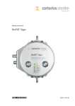
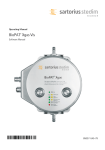
Operating manual | Betriebsanleitung BioPAT® Xgas 85032-544-12 85032-544-12 English – page 3 In cases involving questions of interpretation, the German-language version shall prevail. Deutsch – Seite 37 Im Auslegungsfall ist die deutsche Sprache maßgeblich. The enclosed CD contains the operating instructions as a PDF file in various international languages. If the CD is missing, you can obtain a copy form us by specifying the order number: Order number: 85037-548-53 Sartorius Stedim Biotech GmbH Technical Editorial Department August-Spindler-Strasse 11 37079 Goettingen, Germany [email protected] www.sartorius-stedim.com System Requirements: – Windows, MacOS X – Browser with JavaScript enabled – PDF-Reader Use start.html to run the application Important Note: The data and information contained in this manual were compiled with the greatest of care. Notwithstanding the scrupulous attention paid to preparing this document, no absolute guarantee of its accuracy can be given. Please notify us if any information is missing that is important for you or if you find any errors. Contents 1.Introduction . . . . . . . . . . . . . . . . . . . . . . . 1.1Function. . . . . . . . . . . . . . . . . . . . . . . 1.2 Target Group. . . . . . . . . . . . . . . . . . 1.3Notes on Using these Instructions . . . . . . . . . . . . . . . . . . . 4 4 4 4 2.Safety Instructions. . . . . . . . . . . . . . . . 6 2.1 General Information . . . . . . . . . . 6 2.2 Authorized Personnel . . . . . . . . . 6 2.3 Intended Usage. . . . . . . . . . . . . . . . 6 2.4 Limitations of Use and Misuse. 7 2.5 Process-related Hazards. . . . . . . 7 3.Design and Function . . . . . . . . . . . . . 8 3.1 Measurement Principles. . . . . . . 8 3.1.1 Pressure Measurement. . 10 3.1.2 Humidity Measurement .10 3.1.3 CO2 Measurement. . . . . . . 10 3.1.4 O2 Measurement. . . . . . . . . 10 4.Installation. . . . . . . . . . . . . . . . . . . . . . . . . 11 4.1Equipment. . . . . . . . . . . . . . . . . . . . . 11 4.1.1 Unboxing and Assembling . . . . . . . . . . . 12 4.2Setup. . . . . . . . . . . . . . . . . . . . . . . . . . 15 4.3Assembly . . . . . . . . . . . . . . . . . . . . . . 15 4.4Connection. . . . . . . . . . . . . . . . . . . . 16 4.5Arrangement on the Bioreactor and Assembly. . . . . 22 5.Operating Information. . . . . . . . . . . . 23 5.1 Safety Instructions. . . . . . . . . . . . 23 5.2 In-process Exhaust Air Analysis. . . . . . . . . . . . . . . . . . . . 23 5.2.1 Switching on the BioPAT® Xgas. . . . . . . . . . . . 24 5.2.2 In-process Measurement. . . . . . . . . . . 25 5.2.3 Sensor Status Display via LEDs. . . . . . . . . 27 5.3Troubleshooting. . . . . . . . . . . . . . . 28 5.3.1 Faults or Malfunctions from Moisture in the Exhaust Air. . . . . . . 28 5.3.2 Leaktightness Test . . . . . . 29 6.Maintenance and Service. . . . . . . . . 30 6.1Maintenance by the Customer. . . . . . . . . . . . 30 6.1.1 Calibration. . . . . . . . . . . 30 6.1.2 Filter Replacement. . . . . . 31 7.Appendix. . . . . . . . . . . . . . . . . . . . . . . . . . . 34 7.1Calibration Table. . . . . . . . . . . . . . 34 8.Technical Data. . . . . . . . . . . . . . . . . . . . . 35 Contents 3 1. Introduction 1.1 Function This operating manual describes the safe installation and use of the BioPAT® Xgas. The operating personnel must read these instructions prior to operational startup. These instructions should always be available at the workplace. 1.2 Target Group These operating instructions are designed for qualified personnel. Only qualified personnel may set up BioPAT® Xgas, connect it to the bioreactor or perform in-process operation or maintenance. 1.3 Notes on Using these Instructions All information in these operating instructions considers the state of the art, the applicable standards and guidelines, and our many years of experience and knowledge. These operating instructions provide you with all the information necessary to install and operate the BioPAT® Xgas (referred to as “device” in the following). The operating instructions must be read and used by all persons entrusted with the operation, service, cleaning, and troubleshooting of the device. This applies particularly to the safety instructions listed. t Please read these operating instructions carefully and completely before using this device. t These instructions are part of the product. Keep them in a safe and easily accessible place near the device’s site of installation. t If the instructions should be lost or misplaced, please contact Sartorius for a replacement or download the latest version from our website: www.sartorius.com 4 Introduction Symbols Used As a means of instruction and direct warning against hazards, all text statements to be particularly noted in these operating instructions will be marked as follows: This symbol denotes a possible danger with risk that moderate or minor injury may result if it is not avoided This symbol denotes a danger with low risk that could result in property damage if it is not avoided. This symbol indicates useful information or a function | setting on the device, or that caution should be exercised while working. The following presentations will also be used: −− Texts that follow this mark are lists. t Texts that follow this mark describe activities that must be carried out in the specified order. yy Texts that follow this mark describe the result of an action. „ “ Texts in quotes are references to other chapters or sections. Introduction 5 2. Safety Instructions 2.1 General Information Sartorius Stedim Biotech GmbH supplies the BioPAT® Xgas after careful testing in ready-for-operation condition. This manual contains instructions for the safe operation of the BioPAT® Xgas. You may only operate the device under conditions that comply with the specifications stated in this manual and the information on the manufacturer’s ID label. 2.2 Authorized Personnel The following persons may carry out the actions described here: Operations Persons Assembly and connection at | to the Trained and qualified personnel bioreactor; function test, basic calibration of the operator or service technicians of during servicing and maintenance Sartorius Stedim Biotech GmbH Operation, in-process 1-point calibration Personnel who has read this documentation and is familiar with the operation of bioreactors Factory maintenance and service Service Department of Sartorius Stedim Biotech GmbH or the sensor manufacturer. 2.3 Intended Usage The BioPAT® Xgas is a gas sensor for measuring carbon dioxide and oxygen contents in the defined concentration range and under the conditions described in the y Technical Data. It is used to monitor metabolic activities during biological processes such as fermentations. 6 Safety Instructions 2.4 Limitations of Use and Misuse Danger of malfunctions and damage to the sensor under impermissible measuring conditions. The BioPAT® Xgas is not designed according to the ATEX Directive. Do not use the sensor – in flammable or explosive atmospheres or with such gases! – in gases with polymers or silicone components – in gases with halogens like F, Cl, Br etc., CFC – in gases with SOx and H2S. Prevent water or humidity (RH <75%) from entering into the sensor when the sensor is switched on. Dry the sensor when humidity condenses in the exhaust line and condensate has entered into the sensor. The BioPAT® Xgas is unsuitable for use as safety equipment for system gas monitoring or as a gas warning device. This constitutes misuse. 2.5 Process-related Hazards Risk of poisoning for persons when CO2 is released into the room. Risk of inflammation for flammable materials if gases enriched with oxygen escape into the room air. Determine the max. concentrations of gas released into the room and evaluate whether they could lead to hazardous situations, e.g. if the room ventilation fails. Ensure that your work area is well ventilated or connect the BioPAT® Xgas to the available exhaust air fittings in your laboratory. Check all connections for leaks. Safety Instructions 7 3. Design and Function The BioPAT® Xgas combines one oxygen and one carbon dioxide sensor featuring automatic compensation of humidity and pressure into one compact analyzer. The gas to be analyzed flows through the integrated flow adapter past the measuring chambers. During this process, the pressure, humidity, oxygen and carbon dioxide concentration are measured. The sensors measure the gases in the concentration ranges and under the conditions for which they were designed; observe the y Technical Data. The analyzer transfers the measurements to the control unit of the bioreactor, e.g. the DCU systems of bioreactors BIOSTAT® Cplus, B and B-DCU II. The measurement and control system shows measurements on the display, as configured in the settings. Observe the operating instructions for the measurement and control system. 3.1 Measurement Principles The analyzer features 4 different measuring components: 1. Pressure measurement 2. Humidity measurement 3.CO2 measurement 4.O2 measurement 8 Design and Function Electronics Pressure and humidity measurement CO2 IR sensor ZrO2 O2 sensor For hoses | pipes AD4 mm up to 14“ Fig. 1: schematic illustration of complete installation In order to prevent humidity contained in the exhaust air in the BioPAT® Xgas from condensing, the sensor housing is heated. Warming up prior to initial startup as well as every time the device is disconnected from the power supply will take about an hour. The sensor won’t provide any valid readings during heating. Design and Function 9 3.1.1 Pressure Measurement A piezoresistive silicon pressure sensor is used to measure the pressure. 3.1.2 Humidity Measurement A capacitive polymer sensor is used to measure the humidity. 3.1.3 CO2 Measurement The CO2 sensor comprises an IR radiation source, a detector and the reflection measuring cell (Fig. 2). The infrared beam is reflected by the gas-filled measuring adapter. The light, now weakened by the CO2, is measured by the detector. A translucent sapphire disc prevents the optical components from getting soiled by constituents of exhaust air. Fig. 2: Measuring setup of the CO2 sensor 3.1.4 O2 Measurement The BioPAT® Xgas oxygen sensor is based on an oxygen pump cell and runs independently of reference gases. Applying voltage to the cell moves the oxygen ions from the cathode to the anode and generates current. Through a diffusion barrier in front of the cathode, a saturation current is generated by increasing the supply voltage, which allows measurement of the ambient oxygen concentration. Fig. 3: Measuring setup of the O2 sensor 10 Design and Function 4. Installation 4.1 Equipment Danger of malfunctions when damaged during transport and when operated under process conditions that do not comply with the device specifications. A Fig. 4: Analyzer, signal cable and accessories for mains connection (A) Spare kit 1: SB-20-02-0002, Power supply for BioPAT® Xgas When delivered for or with bench-top bioreactor systems, e.g. BIOSTAT® B or B-DCU II, the BioPAT® Xgas and accessories are packaged in a safe-to-transport manner. When delivered with sterilizable-in-place (SIP) bioreactors, e.g., BIOSTAT® CPlus, the BioPAT® Xgas sensor is installed on the bioreactor frame. The sensor accessories are packaged separately in a safe-to-transport manner. 1. Carefully unpack the packaged devices and the connecting accessories. 2. Check if the delivery is complete. 3.Check all delivered components for any damage. If transport damage has occurred, send a claim as soon as possible. The equipment supplied with BioPAT® Xgas, including the connection kit, is comprised of: −− The analyzer BioPAT® Xgas. −− Flow adapters for connection to the exhaust line. −− For bench-top bioreactors: connection hoses, e.g., silicon hoses with diameter 6 mm, for connecting the exhaust filter to the BioPAT® Xgas Sensor. −− For sterilizable-in-place (SIP) bioreactors: installation kit already attached to the bioreactor frame. −− Signal transmission cable to the BioPAT® Xgas on the control unit. Installation 11 −− When delivered with the external power supply, the male connector must match the power connection in laboratory. The delivery contains the matching plug adapter. −− A replacement BioPAT® Xgas power supply kit pack can be ordered from Sartorius (SB-20-02-0002), see „Fig. 5: Cable set included“. 4.1.1 Unboxing and assembling The flow adapter of the BioPAT® Xgas is not preassembled and will be delivered in a small box together with the BioPAT® Xgas (fig 4a). Before the installation, it must be connected to the BioPAT® Xgas. Fig. 4a: Unboxing E A D C B Fig. 4b: Preparing the assembling (B) Spare kit 2: SB-20-02-0001, Spare part kit for BioPAT® Xgas Fig. 4c: Filters 12 Installation For the assembling you will need (fig. 4b): 1. The BioPAT® Xgas (A) 2. The TORX T20 screwdriver (D) 3. The mounting base plate (C) 4. The flow adapter (E) 5. Bag with 2 flat head screws M4x6 TORX for the wall mounting and 4 screws M4x16 TORX for the flow adapter (B). 6. Bag with flow path filter set BioPAT® Xgas (B). To assemble the BioPAT® Xgas proceed in the following steps: 1. First, place the filters and gaskets on the flow adapter. All required filters and gaskets are in the filter set for the BioPAT® Xgas (SB-20-02-0001, Spare part kit for BioPAT® Xgas). For each recess there are two different filters. There is a flat filter (fig. 4c: A) and a thicker filter (fig. 4c: B). The flat filter is hydrophobic and the thicker is the particulate filter. For each recess there is a gasket, a flat filter and a thicker filter in the filter set (fig. 4c). 2. Insert the flat filter into the recesses (fig. 4e). 3. Place the gaskets in the recesses (fig. 4f) 4. Insert the thicker filters into the recesses (fig. 4g). If the filters don´t fit in the recesses, it might be necessary to push them gently into place (fig. 4h). Fig. 4d: Filters and gaskets Fig. 4e: Insert flat filter Fig. 4f: Place gaskets Fig. 4g: Insert second filter Fig. 4h: Fit in filter Installation 13 Fig. 4i: Put screws in Fig. 4j: Tighten screws Fig. 4k: Fit base plate 14 Installation 5. Now place the 4 TORX screws M4x16 (fig. 4b: E) in the bores of the BioPAT® Xgas without screwing. This will make it easier to place the BioPAT® Xgason the right spot on the flow adapter (fig. 4i). 6. Place the BioPAT® Xgas on the flow adapter. Tighten the 4 screws with the screw driver TORX. 7. Put the wall mounting plate on the flow adapter and use the two flat head screws M4x6 (fig. 4b: E) to fix the base plate to the sensor (fig. 4k). 4.2 Setup Danger of damage to the control and supply unit of the bioreactor. The BioPAT® Xgas module weighs approx. 3 kg. Do not place the module on the control and supply unit of the bioreactor and do not fasten it to its side panels. The housing panels cannot carry the weight of the BioPAT® Xgas. 4.3 Assembly When using bioreactor bench-top systems, mount the BioPAT® Xgas module on a flat surface with non-slip rubber feet. 1.Observe the lengths of the cables and connection lines. 2.Place the BioPAT® Xgas on the work table next to the bioreactor so that you can comfortably connect all equipment. Mounting the BioPAT Xgas on a fixed vertical surface is possible with the approriate 6.6 mm screws. When using sterilizable-in-place (SIP) bioreactors, the BioPAT® Xgas module is attached to the bioreactor frame using an installation kit. 1.Avoid contact between the signal cable and the outer surface of the vessel. 2. Ensure that no hot steam is directed at the sensor and signal cable. Installation 15 4.4 Connection Making connections while the BioPAT® Xgas is still connected to power or with the wrong kind of voltage can cause damage. Use only cables from the equipment supplied with the BioPAT® Xgas and | or the bioreactor equipment. The module is not equipped with an ON | OFF switch. First, leave the control unit and | or supply unit of the bioreactors switched off and | or disconnect the external power adapter from the mains current. First connect the cables for the signal transmission and power supply. Connect the exhaust line from the BIOSTAT® B and B-DCU II 1.Make sure that the lines of the culture vessel contain no condensation. 2. Connect the exhaust line to the BioPAT® Xgas. 3.If exhaust air entering the room air can be regarded as safe, you can leave the BioPAT® Xgas outlet open. If the exhaust air contains gases in potentially hazardous concentrations, connect the outlet to the exhaust air fittings in the laboratory. Connecting the Cables to the BIOSTAT® B and B-DCU II −− Use only the cables that are especially designed for this purpose. Observe the specifications below and the “Technical Documentation on the Bioreactor“: Fig. 5: Cable set included Wait until the BioPAT® Xgas has reached room temperature. 16 Installation Connecting the Y cable Take the Y cable of the BioPAT® Xgas. Connect the female connector with the three cable outputs to the left plug of the BioPAT® Xgas. Connect the BioPAT® Xgas to the power supply. Installation 17 Connecting to BIOSTAT® B (Serial No. < 1000) Connect the analog signal outputs of the BioPAT® Xgas to the analog inputs on the Control Tower of the BIOSTAT® B as follows: Take the analog Y signal cable. Connect the plug of the Y cable labeled “Xgas” to the right female connector of the BioPAT® Xgas. Connect the plug of the Y cable labeled “Ext. Sig.-A” to the female connector “Ext.Sig.-A1/2” of the BIOSTAT® B. Connect the plug of the Y cable labeled “Ext. Sig.-A” to the female connector “Ext.Sig.-B1/2” of the BIOSTAT® B. 18 Installation Connecting to BIOSTAT® B-DCU II Connect the analog signal outputs of the BioPAT® Xgas to the analog inputs on the Control Tower of the BIOSTAT® B-DCU II as follows: Take the analog Y signal cable. Connect the plug of the Y cable labeled “Xgas” to the right female connector of the BioPAT® Xgas. Connect the plug of the Y cable labeled “Ext. Sig.-A” to the female connector “Ext.Sig.-A” of the BIOSTAT® B-DCU II. Connect the plug labeled “Ext. Sig.-B” of the Y cable to the female connector “Ext.Sig.-B” of the BIOSTAT® B-DCU II. . Installation 19 Connecting to BIOSTAT® B (Serial No. > 1000) Connect the analog signal outputs of the BioPAT® Xgas to the analog inputs on the control tower of the BIOSTAT® B as follows: Take the analog signal cable. Connect the cable plug labeled “Xgas” to the righthand socket of the BioPAT® Xgas. Connect the cable plug labeled “Ext. Sig.A1/B1” or “Ext. Sig.C1/D1” to the “Ext.Sig.-A1/B1” or “Ext.Sig.-C1/D1” socket of the BIOSTAT® B depending on the DCU signal configuration for off-gas analysis. 20 Installation Connecting to BIOSTAT® Cplus Connect the analog signal outputs of the BioPAT® Xgas to the control tower of the BIOSTAT® Cplus as follows: Take the analog serial connection cable. Connect the cable plug labeled “Xgas” to the righthand socket of the BioPAT® Xgas. Connect the cable plug labeled “Ext. Sig.-A” to the “Ext. Sig.1-2” socket of the BIOSTAT® Cplus. Installation 21 4.5 Arrangement on the Bioreactor and Assembly F A C2 D B E G2 C1 G1 Fitting the BioPAT® Xgas to a BIOSTAT® Cplus: A:BioPAT® Xgas Sensor & flowpath module B:Support C1/C2: Valves for switching the exhaust feed D: Pneumatic pressure control valve E: Pipe to BioPAT® Xgas sensor F:Pipe between exhaust feed and pressure control valve. G1/G2:Outlets into the ambient air or for connection to the laboratory vent, if necessary. 22 Installation 5. Operating Information 5.1 Safety Instructions Hazards for users from the composition of the exhaust air: – CO2: Danger of suffocation from release into the room air; – O2: Combustion of flammable materials at high O2 concentrations or potential production of oxy-hydrogen gas with H2. When channeling into room air, ensure that your work area is well ventilated. If constituents, e.g. generated by reactions with other substances, may be hazardous, channel the exhaust air into ventilation fittings on the laboratory side. Temperatures in the exhaust air > 40°C or oxygen-free exhaust air can damage the sensors in the BioPAT® Xgas. The pure nitrogen used during zero-point calibration of the DO sensor in the culture vessel must not escape into the BioPAT® Xgas. At process temperatures >40°C and during zero point calibration of the DO sensor with nitrogen, leave the BioPAT® Xgas disconnected from the exhaust line and | or block the inlet lines or disconnect them temporarily. 5.2 In-process Exhaust Air Analysis Danger of burns! After connecting the power supply, the housing of the BioPAT® Xgas heats up due to warming. Do not touch it any longer or only when wearing gloves. Operating Information 23 Compare the process conditions with the bioreactor specifications in the “Technical Data“. Do not connect the device for gases or under process and ambient conditions it is not designed for. 5.2.1 Switching on the BioPAT® Xgas After initial start-up and when the power supply is disconnected, the BioPAT® Xgas requires a warming phase of about 1 h until it can operate within the limits of the measuring range, see “Technical Data“. LEDs on the device display the operation status. Displayed measurements indicate the zero current conducted during warm-up, not the actually measured gas concentrations. Fig. 6: 1-point calibration 1.The BioPAT® Xgas is activated when the bioreactor is switched on or when the power supply is connected. Wait for the device to warm up (approx. 1 h). The LED rings around the buttons light up and indicate the sensor status. During the warm-up phase, the sensor supplies a current signal of approx. 2.3 mA 2.Perform 1-point calibration during initial startup and always when the analyzer indicates you do so. Disconnect the connection or lines from the bioreactor (exhaust air filter) and channel fresh air (0.4% CO2, 20.97% O2 by volume, residual N2) at a flow rate of min. 200 ml/min. Observe the specifications in the “Data Sheet“. Flushing air with a different composition will falsify later measurements. 3.Press the two buttons on the BioPAT® Xgas for 5 seconds. As soon as the left LED is lit up continuously in green, the analyzer is ready for o peration. 24 Operating Information For autoclavable bioreactors: When disconnecting from the exhaust line during preparation of the bioreactor for the process, e.g. for autoclaving, you must not switch off the BioPAT® Xgas. The displayed measurement signal then indicates the measurement of the ambient air. 1.On bioreactors with autoclavable culture vessels, remove any exhaust line already connected to the BioPAT® Xgas. 2.Prepare the bioreactor for the process [y Operating manual for the bioreactor], e.g. sterilization, calibration of the DO sensor and inoculation. 5.2.2 In-process Measurement Temperatures in the exhaust air >40°C or oxygenfree exhaust air can damage the sensors in the BioPAT® Xgas. The pure nitrogen used during zeropoint calibration of the DO sensor in the culture vessel must not escape into the BioPAT® Xgas. Humidity and condensation in the exhaust air can damage the sensors. Ensure that exhaust cooling is always active during measurement. Monitor whether condensation forms in the exhaust line. Abort the measurement if condensation enters the BioPAT® Xgas. Dry the BioPAT® Xgas as described below [y Troubleshooting]. Bioreactors BIOSTAT® B or B-DCU II 1.After autoclaving, set up the culture vessels at the work place. If required, calibrate the zero point of the built-in DO sensor with pure nitrogen. 2.Ensure that the process temperature is < 40°C. 3. Connect the exhaust line to the BioPAT® Xgas. Operating Information 25 BIOSTAT® Cplus bioreactors 1.If the zero point of the DO sensor with oxygen is calibrated, switch the exhaust line to the bypass via the solenoid valves. 2.Calibrate the zero point of the built-in DO sensor with nitrogen. 3.Ensure that the process temperature is below 40°C. 4.Switch the exhaust line to the BioPAT® Xgas via the solenoid valves. For bioreactors with automatic valves, check that the valves have switched using the control. If the exhaust is not directed to the ambient air, ensure that both the BioPAT® Xgas and the bypass are connected to their joint line. Conducting measurements with the BioPAT® Xgas −− Every time the device is connected to or disconnected from the power supply, it will take about an hour to warm up. The displayed measurement signal is related to the current signal of approx. 2.3 mA from the sensor during the warm-up phase −− If the measurement and control system of the bioreactor only indicates the measured values, monitor the course of process on the operator display. −− If the measurement and control system of the bioreactor can log the measured values, configure this log as described in the [y Operating manual for the control system]. 26 Operating Information 5.2.3 Sensor Status Display via LEDs LED status Description Possible Causes green Sensor is ready for operation yellow Warm-up phase, can take up to 60 minutes The sensors must reach operating temperature, otherwise the measurements are incorrect green | yellow Prompt to perform a 1-point calibration Always at the initial startup, or when the sensor signal shows extreme changes green flashing 1-point calibration running Calibration started by pressing the two buttons for 5 seconds green | yellow flashing Factory calibration required Strong signal alteration due to age of the sensor or incorrect 1-point calibration red Sensor not working Sensor currently starting up; signal too weak; sensor defective Fig. 7: Buttons with LEDs Operating Information 27 5.3 Troubleshooting 5.3.1 Faults or Malfunctions from Moisture in the Exhaust Air Humidity, e.g. condensation in the exhaust line, can damage the sensors in the BioPAT® Xgas or disrupt the exhaust measurement. In the event of moist exhaust air that is warmer than the ambient air, condensation can form in the exhaust line and be forced into the module. Check the exhaust line regularly for any condensation that may have formed. Allow the condensation to drain off and dry the BioPAT® Xgas with compressed air. You do not need to interrupt the measurement. In doing so, note that the device is now determining the gas concentrations in the air being pumped through. System interruptions on BIOSTAT® B or B-DCU II 1.Disconnect the tubing from the inlet to the BioPAT® Xgas. Allow the condensation to drain off, e.g. into a vessel or down the lab drain. 2.Connect clean, dry compressed air and flush the BioPAT® Xgas. 3.Reconnect the exhaust air segment tubing to the BioPAT® Xgas. If larger amounts of condensation occur, and you continually have to dry the BioPAT® Xgas, you can channel the exhaust air through a condensation trap [y Information on request]. 28 Operating Information 5.3.2 Leaktightness Test Ambient air entering the exhaust air disrupts the measurement. Check whether the tubing, lines, connections and the BioPAT® Xgas are leaktight 1.Block the gas outlet of the BioPAT® Xgas or clamp off the lines to the exhaust air fittings in the laboratory. 2.Check whether gas is escaping from tubing, lines, connections or the housing. 3.Replace defective tubing, tighten loose screws and | or fasten the tubing with hose clamps. On pipelines with Tri-Clamp connections, check and replace the Tri-Clamp seals and gaskets. −− If gas is escaping out of the housing of the BioPAT® Xgas, check that the flow adapters are assembled leaktight, e.g. when you have maintained the filter installed there [y Maintenance Instructions] Operating Information 29 6. Maintenance and Service 6.1 Maintenance by the Customer You must calibrate the BioPAT® Xgas sensors regularly. Observe the LED displays on the BioPAT® Xgas analyzer: 6.1.1 Calibration −− Perform the 1-point calibration during initial startup and always when the analyzer indicates you do so. −− Aerate once monthly for approx. 30 minutes with normal fresh air (20.97% by volume O2 | 0.04% by volume CO2) as per specification (see Data Sheet). Next, press the two keys at the same time for 5 seconds (Fig. 8). −− For the recommended annual recalibration, return the sensor to Sartorius Stedim Systems GmbH. 30 Maintenance and Service Fig. 8: Screws for attaching the sensors to the flow adapter 6.1.2 Filter Replacement The flow adapter contains a coarse filter, which you have to maintain and replenish whenever there are impurities or obstructions of the gas flow. Spare parts are obtained on request. For filter replacements: 1.Disconnect all connected lines from the BioPAT® Xgas or disassemble the module from the bioreactor. Remove the mounting plate as necessary. 2.Unscrew the four screws visible from top (see Fig. 8). Remove the base plate and place it to the side so that the filters are visible (Fig. 8) 3.Remove the filters from the recesses and insert new filters. 4.Replace O-rings with pressure marks, porous surfaces or hairline cracks. 5.Re-fasten the base plate and install the BioPAT® Xgas on the bioreactor and | or mount and connect. Fig. 9: Filter replacement Maintenance and Service 31 Replace the BioPAT® Xgas if the sensors are defective. An LED lighting up continuously in red after the startup and warm-up phase indicates malfunctioning or defective sensors. On-site repairs are not possible. Inform the Service Department of Sartorius Stedim Biotech GmbH. Sartorius Stedim Biotech GmbH recommends having the sensor checked and recalibrated once a year at the factory. Moreover, send the sensor back in the event of an incorrect or failed 1-point calibration, in the event of strong signal alteration without major changes to the measuring conditions. Sartorius Stedim Biotech GmbH shall not be liable for repairs made by the customer or any resulting damage, especially in the event of – use of non-approved spare parts. – non-approved technical changes. 1. Inspections can be carried out on-site by authorized service personnel or by any service representative of Sartorius Stedim Biotech GmbH. 2.In the event of service requests or warranty claims, please notify your representative of Sartorius Stedim Biotech GmbH or contact: Sartorius Stedim Systems GmbH Service Robert-Bosch-Strasse 5–7 D-34302 Guxhagen, Federal Republic of Germany Phone +49 (0) 5665-407-0 / Fax +49 (0) 5665407-2200 3. You can return defective devices or parts. 32 Maintenance and Service Returned devices must be clean and in hygienically flawless condition and packed carefully, e.g. in accordance with the safety guidelines applicable to the process. 1.Inform the Service Department in the event of a return. 2.Provide a Declaration of Decontamination with the return shipment. The Service Department must be able to read it before opening the packaging. The information must detail the media and microorganisms the BioPAT® Xgas has come into contact with and the measures taken to disinfect and decon taminate it. Maintenance and Service 33 7. Appendix 7.1 Calibration Table Only have the complete calibration conducted by Sartorius Stedim Biotech GmbH Service. Conduct the monthly 1-point calibration as described in Section y “6.1 1-Point Calibration“ on page 27. Also calibrate this way every time after separating sensor head and measuring adapter. Log the calibrations performed, e.g. in the table below. Date Procedure Conditions Name Complete calibration 25 °C, 1 bar BioPAT Xgas 1-Point calibration 34 Appendix Signature ® 8. Technical Data O2 Sensor Unit Gas O2 Concentration range 1 – 50% by volume, others available upon request Measuring principle Zirconium dioxide Accuracy < 0.2% FS2 ± 3% Rdg2 on value Drift < ± 2% value | year Lifetime of sensor element Approx. 15,000 operating hours | approx. 2 years Temperature inside the sensor unit 580°C | 1076°F CO2 Sensor Unit Gas CO2 Concentration range 0 – 10% by volume, others available upon request Measuring principle Infrared Accuracy < 0.2% FS2 ± 3% Rdg2 on value Drift < ± 2% value | year Lifetime of sensor element Approx. 25,000 operating hours | approx. 3 years Temperature inside the sensor unit 3°C | 5.4°F higher than process temperature General Information Temperature range 15 – 40°C | 59°F – 104°F Pressure range 0.8 – 1.3 bar 11.6 – 18.85 psi absolute pressure Humidity range 0 – 100% relative operating humidity, integrated humidity compensation Housing Stainless steel, IP65 Dimensions (L + W + H) | Weight W + L + H = 170 + 150 + 120 mm (6.69” + 5.91” + 4.72”)3 | weight = 4 kg (8.82 lb) Mechanical connection 4“ – 14“, others on request Materials in contact with process Stainless steel AISI 316 L (1.4404), fluoroelastoer, gas sapphire, PTFE, polymer H.L., nitrite Filters PTFE 0.22 μm, PTFE 5 μm Power supply 24 V 1A Technical Data 35 Electronic Connections Power supply 12-pin M12 male connector Signal output 12-pin M12 female connector Electronic output Active output, maximum 505 Ohm at 24V power supply RS-232, RS-485, USB, Ethernet (with BACCom), Modbus Storage 0 - +60°C; < 75% RF non-condensing Maintenance 1-point calibration with fresh air (0.04 vol.% CO2, 20.97 vol.% O2) once a month (other conditions possible), optional factory calibration once a year CE | FCC | ICES EN61326-1:2006 | FCC 15:2009 Subpart 107/109, ICES001:2006 Remarks Don't use in explosive atmosphere, in anoxic atmosphere, in gases with polymers or silicon components or in gases with halogens (F, Cl, Br, etc.), CFC or SOX and H2S 36 Technical Data Inhalt 1.Einleitung. . . . . . . . . . . . . . . . . . . . . . . . . 38 1.1Funktion. . . . . . . . . . . . . . . . . . . . . . . 38 1.2Zielgruppe. . . . . . . . . . . . . . . . . . . . . 38 1.3 Hinweise zu dieser Anleitung. 38 2.Sicherheitshinweise . . . . . . . . . . . . . . 40 2.1Allgemeines . . . . . . . . . . . . . . . . . . . 40 2.2 Autorisiertes Personal. . . . . . . . . 40 2.3Bestimmungsgemäße Verwendung. . . . . . . . . . . . . . . . . . . 40 2.4Verwendungsbeschränkungen und Fehlgebrauch. . . . . . . . . . . . . 41 2.5 Prozessabhängige Gefahren. . 41 3. Aufbau und Funktion . . . . . . . . . . . . 42 3.1Messprinzipien . . . . . . . . . . . . . . . . 42 3.1.1 Druckmessung. . . . . . . . . . 44 3.1.2 Feuchtigkeitsmessung . . 44 3.1.3 CO2-Messung . . . . . . . . . . . 44 3.1.4 O2-Messung. . . . . . . . . . . . . 44 4.Installation. . . . . . . . . . . . . . . . . . . . . . . . 45 4.1Ausrüstungen . . . . . . . . . . . . . . . . . 45 4.1.1 A uspacken und Zusammenbauen. . . . . . . 46 4.2Aufstellung. . . . . . . . . . . . . . . . . . . . 49 4.3Montage. . . . . . . . . . . . . . . . . . . . . . 49 4.4Anschluss. . . . . . . . . . . . . . . . . . . . . . 50 4.5Ubersichtsdarstellung für Aufstellung und Montage. . . . . 56 5.Betriebshinweise. . . . . . . . . . . . . . . . . . 57 5.1Sicherheitshinweise. . . . . . . . . . . 57 5.2 Abluftanalyse im Prozess. . . . . . 57 5.2.1 Einschalten des BioPAT® Xgas. . . . . . . . 58 5.2.2 Messbetrieb im Prozess.59 5.2.3 Zustandsanzeige des Sensors über LEDs . . 61 5.3Fehlerbehebung. . . . . . . . . . . . . . . 62 5.3.1 Störungen durch Feuchtigkeit in der Abluft. . . . . . . . . . . . . . . . . . . 62 5.3.2 Dichtheitsprüfung. . . . . . 63 6. Wartung und Service. . . . . . . . . . . . . 64 6.1 Kundenseitige Wartung. . . . . . . 64 6.1.1 Kalibrierung . . . . . . . . . . . . 64 6.1.2 Filterwechsel. . . . . . . . . . . . 65 7.Anhang. . . . . . . . . . . . . . . . . . . . . . . . . . . . 68 7.1Kalibrationstabelle. . . . . . . . . . . . 68 8. Technische Daten. . . . . . . . . . . . . . . . . 69 Inhalt 37 1. Einleitung 1.1 Funktion Die Betriebsanleitung beschreibt die sichere Einrichtung und Verwendung des BioPAT® Xgas. Das Bedienpersonal muß diese Anleitung vor der Inbetriebnahme lesen. Die Anleitung soll ständig am Arbeitsplatz verfügbar sein. 1.2 Zielgruppe Die Betriebsanleitung richtet sich an ausgebildetes Fachpersonal. Nur solches Personal darf den BioPAT® Xgas aufstellen, am Bioreaktor anschließen und im Prozeß bedienen oder warten. 1.3 Hinweise zu dieser Anleitung Alle Angaben in dieser Betriebsanleitung berücksichtigen den Stand der Technik, die geltenden Normen und Vorschriften sowie unsere langjährigen Erkenntnisse und Erfahrungen. Diese Betriebsanleitung enthält alle Informationen, die Sie für die Installation und Bedienung des BioPAT® Xgas (im Folgenden Gerät genannt) benötigen. Alle Personen, die mit der Bedienung, Wartung, Reinigung und Störungsbeseitigung des Geräts beauftragt sind, müssen diese Betriebsanleitung lesen und anwenden. Das gilt insbesondere für die aufgeführten Sicherheitshinweise. t Lesen sie diese Betriebsanleitung aufmerksam und vollständig durch, bevor Sie mit dem Gerät arbeiten. t Diese Betriebsanleitung ist Teil des Gerätes. Bewahren Sie sie gut erreichbar und sicher am Einsatzort des Geräts auf. t Bei Verlust der Betriebsanleitung können Sie Ersatz anfordern 38 Einleitung Darstellungsmittel Als Hinweis und zur direkten Warnung vor Gefahren sind besonders zu beachtende Textaussagen in dieser Betriebsanleitung wie folgt gekennzeichnet: Dieser Hinweis kennzeichnet mögliche Gefährdungen, die zu mittelschweren oder leichte Körperverletzungen führen können, wenn Sie sie nicht vermeiden Dieser Hinweis kennzeichnet eine Gefährdung mit geringem Risiko, die Sachschäden zur Folge haben könnte, wenn sie nicht vermieden wird. Dieses Symbol kennzeichnet nützliche Informationen oder gibt einen Hinweis zu einer Funktion oder Einstellung an dem Gerät oder zur Vorsicht beim Arbeiten. Des Weiteren werden folgende Darstellungsmittel verwendet: −− Texte, die dieser Markierung folgen, sind Aufzählungen. t Texte, die dieser Markierung folgen, beschreiben Tätigkeiten, die in der vorgegebenen Reihenfolge auszuführen sind. yy Texte, die dieser Markierung folgen, beschreiben das Ergebnis einer Handlung. „ “ Texte in Anführungszeichen sind Verweise auf andere Kapitel oder Abschnitte. Einleitung 39 2. Sicherheitshinweise 2.1 Allgemeines Die Sartorius Stedim Biotech GmbH liefert der BioPAT® Xgas nach sorgfältiger Prüfung in betriebsbereitem Zustand. Diese Anleitung enthält Hinweise für den sicheren Betrieb des BioPAT® Xgas. Verwenden Sie das Gerät nur gemäß den Angaben in dieser Anleitung und unter Bedingungen, die den Spezifikationen auf dem Typenschild entsprechen. 2.2 Autorisiertes Personal Folgende Personen dürfen die hier beschriebenen Tätigkeiten ausführen: Tätigkeiten Personen Montage und Anschluß am Bioreaktor; Funktiostest, Grundkalibrierung bei Wartung geschultes Fachpersonal des Betreibers oder Servicetechniker von Sartorius Stedim Biotech GmbH Bedienung im Betrieb, 1-Punkt Kalibrierung im Prozess Personal, das diese Dokumentation gelesen hat und mit dem Betrieb von Bioreaktoren vertraut ist Werkseitige Wartung, Instandsetzung Service der Sartorius Stedim Biotech GmbH oder des Sensorherstellers. 2.3 Bestimmungsgemäße Verwendung Der BioPAT® Xgas ist ein kompakter Gassensor zur Messung des Kohlendioxid- und Sauerstoffgehaltes im Konzentrationsbereich und unter den Bedingungen, wie in den y Technischen Daten beschrieben. Er dient zur Überwachung und Beurteilung von Stoffwechselvorgängen biologischer Prozesse, z. B. in Fermentationen. 40 Sicherheitshinweise 2.4 Verwendungsbeschränkungen und Fehlgebrauch Gefahr von Fehlfunktionen und Beschädigung des Sensors bei unzulässigen Messbedingungen. Der BioPAT® Xgas ist nicht ausgelegt gemäß ATEXRichtlinie. Verwenden Sie den Sensor nicht – in brennbaren oder explosiven Atmosphären oder mit solchen Gasen! – bei Gasen, die Polymere oder Silikonkomponenten enthalten – bei Gasen die Halogene enthalten, z.B. F, Cl, Br etc., CFC – bei Gasen mit SOx und H2S. Vermeiden Sie das Eindringen von Wasser oder Feuchtigkeit (RH <75%) in den Sensor, wenn der Sensor ausgeschaltet ist. Trocknen Sie den Sensor, wenn Feuchtigkeit in der Abluftleitung kondensiert und Kondensat in den Sensor eingedrungen ist. Der BioPAT® Xgas ist ungeeignet zum Einsatz als Sicherheitsausrüstung für die Gasüberwachung in Anlagen oder als Gaswarngerät. Dies ist ein Fehlgebrauch. 2.5 Prozessabhängige Gefahren Vergiftungsgefahr für Personen bei Anreicherung von CO2 im Raum. Entzündungsgefahr für entflammbare Stoffe, wenn mit O2 angereicherte Gase in die Raumluft gelangen. Ermitteln Sie die max. Gaskonzentrationen bei Anreicherung im Raum und bewerten, ob dies zu gefährlichen Situationen führen kann, z.B. bei Ausfall der Raumlüftung. Sorgen Sie am Arbeisplatz für gute Belüftung oder schließen den BioPAT® Xgas an verfügbare Ablufteinrichtungen des Labors an. Prüfen Sie alle Anschlüsse auf Dichtigkeit. Sicherheitshinweise 41 3. Aufbau und Funktion Der BioPAT® Xgas kombiniert je einen CO2- und O2-Sensor mit einer automatischen Feuchte- und Druckkompensation in einem kompakten Analyse gerät. Das zu untersuchende Gas strömt über den integrierten Flussadapter an drei Messkammern vorbei, die Druck, Feuchte sowie CO2- und O2-Gehalt messen. Die Sensoren messen die Gase in den Konzentrationsbereichen und unter den Bedingungen, für die sie ausgelegt wurden, beachten Sie das Kapitel „Technische Daten“. Das Analysegerät überträgt die Messwerte an die Kontrolleinheit des Bioreaktors, z.B. die DCU-Systeme der Bioreaktoren BIOSTAT® Cplus, B und B-DCU II. Das Mess- und Regelsystem zeigt Messwerte am Display an, wie in der Konfiguration vorgegeben. Beachten Sie die Betriebsanleitung zum Mess- und Regelsystem. 3.1 Messprinzipien Der Analysator beinhaltet 4 Messkomponenten: 1.Druckmessung 2.Feuchtigkeitsmessung 3.CO2-Messung 4.O2-Messung 42 Aufbau und Funktion Elektronik ZrO2-O2-Sensor Druck- und Feuchtemessung CO2-IR-Sensor Für Schläuche | Rohre AD4 mm bis 14“ Abb. 1: Schematische Darstellung des Gesamtaufbaus Damit in der Abluft enthaltene Feuchtigkeit im BioPAT® Xgas nicht auskondensieren kann, ist das Sensorgehäuse beheizt. Das Aufwärmen dauert ca. 1 Stunde, sowohl bei der ersten Inbetriebnahme als auch nach jeder Trennung der Spannungsversorgung Während der Aufwärmzeit gibt der Sensor keine gültigen Messwerte aus. Aufbau und Funktion 43 3.1.1 Druckmessung Ein piezoresistiver Siliziumdrucksensor misst den Druck. 3.1.2 Feuchtigkeitsmessung Ein kapazitiver Polymerfühler misst die Feuchtigkeit. 3.1.3 CO2-Messung Der CO2-Sensor besteht aus der IR-Strahlungsquelle, dem Detektor und der Reflektionsmesszelle (Abb. 2). Der gasgefüllte Messadapter reflektiert den InfrarotLichtstrahl. Der Detektor misst das vom CO2 geschwächte Licht. Die lichtdurchlässige Saphirscheibe verhindert ein Verschmutzen der optischen Bauteile durch Inhaltsstoffe der Abluft. Abb. 2:Messaufbau des CO2-Sensors Abb. 3: Messaufbau des O2-Sensors 44 Aufbau und Funktion 3.1.4 O2-Messung Der Sauerstoffsensor im BioPAT® Xgas basiert auf einer Sauerstoffpumpzelle und ist unabhängig von Referenzgasen. Bei Anlegen einer Spannung an die Zelle bewegen sich Sauerstoffionen von der Kathode zur Anode und erzeugen einen Strom. Durch eine Diffusionsbarriere vor der Kathode entsteht beim Erhöhen der Spannung ein Sättigungsstrom, der ein Maß für die Sauerstoffkonzentration in der Abluft ist. 4. Installation 4.1 Ausrüstungen Gefahr von Fehlfunktionen bei Beschädigung durch den Transport und bei Prozessbedingungen, die nicht den Gerätespezifikationen entsprechen. A Abb. 4: Analysegerät, Signalkabel und Zubehör zum Netzanschluss (A) Ersatzteilkit 1: SB-20-02-0002, Netzteil für BioPAT® Xgas Bei Lieferung für oder mit Tischgeräten der Bioreaktoren, z.B. BIOSTAT® B oder B-DCU II, sind der BioPAT® Xgas und das Zubehör transportsicher verpackt. Bei Lieferung mit insitu-sterilisierbaren Bioreaktoren, z. B. BIOSTAT® Cplus, ist der BioPAT® Xgas Sensor am Gestell des Bioreaktors installiert. Das Zubehör des Sensors ist separat transportsicher verpackt. 1.Packen Sie verpackte Geräte und Anschlusszubehör vorsichtig aus. 2. Prüfen Sie die Vollständigkeit der Lieferung. 3.Prüfen Sie alle gelieferten Bauteile auf Beschädigungen. Reklamieren Sie Transportschäden schnellstmöglich. Der Lieferumfang des BioPAT® Xgas mit Anschluß-Kits enthält: −− Das Analysegerät BioPAT® Xgas. −− Durchflussadapter für den Anschluss an unterschiedliche Abluftleitungen. −− Für Tischbioreaktoren: Anschlussschläuche, z. B. Silikonschläuche d 6 mm, für die Verbindung vom Abluftfilter zum BioPAT® Xgas Sensor. −− Für insitu-sterilisierbare Bioreaktoren: Installationssatz, der bereits an dem Gestell des Bioreaktors angebracht ist. −− Kabel zur Signalübertragung vom BioPAT® Xgas an die Kontrolleinheit. −− Bei Lieferung mit dem externen Netzteil muss der Stecker zum Netzanschluss im Labor passen. Die Lieferung enthält passende Steckadapter. Installation 45 −− Bei Sartorius kann ein Ersatz-Netzteilkit für BioPAT® Xgas bestellt werden (SB-20-02-0002), siehe „Abb. 5: Kabelsatz im Lieferumfang“. 4.1.1 Auspacken und Zusammenbauen Der Durchflussadapter des BioPAT® Xgas ist nicht vormontiert und wird in einem kleinen Karton zusammen mit dem BioPAT® Xgas (Abb. 4a) geliefert. Vor der Installation muss er an den BioPAT® Xgas angeschlossen werden. Abb. 4a: Auspacken E A D C B Abb. 4b: Zusammenbau vorbereiten (B) Ersatzteilkit 2: SB-20-02-0001, Ersatzteilkit für BioPAT®Xgas Abb. 4c: Filter 46 Installation Für den Zusammenbau brauchen Sie (Abb. 4b): 1. den BioPAT® Xgas (A) 2. den Schraubenzieher TORX T20 (D) 3. die Montagegrundplatte (C) 4. den Durchflussadapter (E) 5. Beutel mit 2 Senkkopfschrauben M4x6 TORX für die Wandhalterung und 4 Schrauben M4x16 TORX für den Durchflussadapter (B ). 6. Beutel mit Filterset für BioPAT® Xgas Durchflussleitung (B). Um den BioPAT® Xgaszusammenzubauen, gehen Sie folgendermaßen vor: 1. Legen Sie zuerst die Filter und Dichtungen auf den Durchflussadapter. Alle erforderlichen Filter und Dichtungen sind im Filterset für den BioPAT® Xgas (SB-20-02-0001, Ersatzteilkit für BioPAT®Xgas) enthalten. Für jede Vertiefung sind zwei unterschiedliche Filter vorgesehen. Ein flacher Filter (Abb. 4c: A) und ein dickerer Filter (Abb. 4c: B). Der flache Filter ist hydrophob und der dickere Filter ist der Partikelfilter. Das Filterset (Abb. 4c) enthält für jede Vertiefung eine Dichtung, einen Flachfilter und einen dickeren Filter (Abb. 4c). 2. Legen Sie den Flachfilter in die Vertiefungen ein (Abb. 4e). 3. Legen Sie die Dichtungen in die Vertiefungen ein (Abb. 4f) 4. Legen Sie die dickeren Filter in die Vertiefungen ein (Abb. 4g). Wenn die Filter nicht in die Vertiefungen passen, kann es erforderlich sein, sie vorsichtig hineinzudrücken (Abb. 4h). Abb. 4d: Filter und Dichtungen Abb. 4e: Einlegen der Flachfilter Abb. 4f: Einlegen der Dichtungen Abb. 4g: Einlegen des zweiten Filters Abb. 4h: Hineindrücken des Filters Installation 47 Abb. 4i: Einstecken der Schrauben Abb. 4j: Festziehen der Schrauben Abb. 4k: Grundplatte anbringen 48 Installation 5. Legen Sie nun die 4 TORX Schrauben M4x16 (Abb. 4b: E) in die Bohrungen am BioPAT® Xgas ein, ohne diese festzuschrauben. So ist es einfacher, den BioPAT® Xgas an der richtigen Stelle am Durchflussadapter zu platzieren (Abb. 4i). 6. Ordnen Sie den BioPAT® Xgas auf dem Durchflussadapter an. Ziehen Sie die 4 Schrauben mit dem TORXSchraubenzieher fest. 7. Legen Sie die Wandmontageplatte auf den Durchflussadapter und befestigen Sie die Grundplatte mit den beiden Senkkopfschrauben M4x6 (Abb. 4b: E) am Sensor (Abb. 4k). 4.2 Aufstellung Gefahr von Schäden an Kontroll- bzw. Versorgungseinheit des Bioreaktors. Das BioPAT® Xgas-Modul wiegt ca. 3 kg. Stellen Sie das Modul nicht auf die Kontroll- oder Versorgungseinheit des Bioreaktors und befestigen Sie es nicht an deren Seitenblechen. Die Gehäusebleche können der BioPAT® Xgas nicht tragen. 4.3 Montage Zum Einsatz bei Tischgeräten der Bioreaktoren ist das BioPAT® Xgas Modul auf einer Platte mit rutschfesten Gummifüßen montiert. 1.Beachten Sie die Längen der Kabel und Anschlussleitungen. 2.Stellen Sie den BioPAT® Xgas auf den Arbeitstisch neben den Bioreaktor, so dass Sie alle Ausrüstungen bequem anschließen können. Der BioPAT Xgas kann mit geeigneten 6,6 mm Schrauben an einer festen vertikalen Fläche montiert werden. Zum Einsatz bei insitu-sterilisierbaren Bioreaktoren ist das BioPAT® Xgas Modul über einen Installationssatz an dem Gestell des Bioreaktors angebracht. 1.Vermeiden Sie den Kontakt zwischen dem Signalkabel und der Kesselaußenoberfläche 2. Stellen Sie sicher, dass kein heißer Dampf an dem Sensor und Signalkabel anströmt. Installation 49 4.4 Anschluss Das Anschließen unter Spannung oder eine falsche Spannungsversorgung können den BioPAT® Xgas beschädigen. Verwenden Sie nur die Kabel aus dem Lieferumfang des BioPAT® Xgas bzw. der Ausrüstung für den Bioreaktor. Das Modul besitzt keinen Ein-/Aus-Schalter. Lassen Sie die Kontrolleinheit bzw. Versorgungseinheit des Bioreaktors zunächst ausgeschaltet bzw. das externe Netzteil vom Stromnetz getrennt. Verbinden Sie zuerst die Kabel für die Signalübertragung und die Stromversorgung. Anschließen der Abluftleitung vom BIOSTAT® B und B-DCU II 1.Stellen Sie sicher, dass die Leitung vom Kultur gefäß kein Kondensat enthält. 2.Verbinden Sie die Abluftleitung mit dem BioPAT® Xgas. 3.Wenn die Abluft unbedenklich in die Raumluft gelangen darf, lassen Sie den Ausgang am BioPAT® Xgas offen. Wenn die Abluft Gase in möglicherweise gefährlichen Konzentrationen enthält, verbinden Sie den Ausgang mit der Ablufteinrichtung im Labor. Anschließen der Kabel beim BIOSTAT®B und B-DCU II −− Verwenden Sie nur die spezielle, hierfür ausgelegten Kabel. Beachten Sie die Angaben unten und die „Technische Dokumentation zum Bioreaktor“: Abb. 5: Kabelsatz im Lieferumfang 50 Installation Warten Sie, bis der BioPAT® Xgas Raumtemperatur erreicht hat. Y-Kabel anschließen Nehmen Sie das Y-Kabel des BioPAT® Xgas. Schließen Sie die Buchse mit den drei Kabelausgängen an den linken Stecker des BioPAT® Xgas an. Schließen Sie den BioPAT® Xgas an die Spannungsversorgung an. Installation 51 Anschluss an BIOSTAT® B (Serien-Nr. </= 1000) Schließen Sie die analogen Signalausgänge des BioPAT® Xgas wie folgt an die analogen Eingänge am Control Tower des BIOSTAT® B an: Nehmen Sie das analoge Y-Signalkabel. Verbinden Sie den mit „Xgas“ beschrifteten Stecker des Y-Kabels mit der rechten Buchse des BioPAT® Xgas. Verbinden Sie den mit „Ext. Sig.-A“ beschrifteten Stecker des Y-Kabels mit der Buchse „Ext.Sig.-A1/2“ des BIOSTAT® B. Verbinden Sie den mit „Ext. Sig.-B“ beschrifteten Stecker des Y-Kabels mit der Buchse „Ext.Sig.-B1/2“ des BIOSTAT® B. 52 Installation Anschluss an BIOSTAT® B-DCU II Schließen Sie die analogen Signalausgänge des BioPAT® Xgas wie folgt an die analogen Eingänge am Control Tower des BIOSTAT® B-DCU II an: Nehmen Sie das analoge Y-Signalkabel. Verbinden Sie den mit „Xgas“ beschrifteten Stecker des Y-Kabels mit der rechten Buchse des BioPAT® Xgas. Verbinden Sie den mit „Ext. Sig.-A“ beschrifteten Stecker des Y-Kabels mit der Buchse „Ext.Sig.-A“ des BIOSTAT® B-DCU II. Verbinden Sie den mit „Ext. Sig.-B“ beschrifteten Stecker des Y-Kabels mit der Buchse „Ext.Sig.-B“ des BIOSTAT® B-DCU II. . Installation 53 Anschluss an BIOSTAT® B (Serien-Nr. größer 1000) Schließen Sie die analogen Signalausgänge des BioPAT® Xgas wie folgt an die analogen Eingänge am Control Tower des BIOSTAT® B an: Nehmen Sie das analoge Signalkabel. Verbinden Sie den mit „Xgas“ beschrifteten Stecker des Kabels mit der rechten Buchse des BioPAT® Xgas. Verbinden Sie den mit „Ext. Sig.A1/B1“ oder „Ext. Sig.C1/D1“ beschrifteten Kabelstecker je nach der DCU-Signalkonfiguration für die Abgasanalyse mit der Buchse „Ext.Sig.-A1/B1“ oder „Ext.Sig.-C1/D1“ am BIOSTAT® B. 54 Installation Anschluss an BIOSTAT® Cplus Schließen Sie die analogen Signalausgänge des BioPAT® Xgas wie folgt am Control Tower des BIOSTAT® Cplus an: Nehmen Sie das analoge Signalkabel. Verbinden Sie den mit „Xgas” beschrifteten Stecker des Kabels mit der rechten Buchse des BIOPAT® Xgas. Verbinden Sie den mit „Xgas” beschrifteten Stecker des Kabels mit der rechten Buchse des BIOPAT® Xgas. Installation 55 4.5 Übersichtsdarstellung für Aufstellung und Montage F A C2 D B E G2 C1 G1 Aufbau BioPAT® Xgas am BIOSTAT® Cplus: A:BioPAT® Xgas Sensor mit Flussadapter B:Halteblech C1/C2: Ventile zum Umschalten der Abgasleitungen D: Pneumatisches Druckregelventil E: Rohrleitung zum BioPAT® Xgas Sensor F:Rohrleitung zwischen Abluftventil und Druckregelventil G1/G2:Abluftausgänge in die Umgebung oder zur Verbindung mit dem Laborabzug (falls erforderlich) 56 Installation 5. Betriebshinweise 5.1 Sicherheitshinweise Gefahren für Anwender durch die Beschaffenheit der Abluft: –CO2: Erstickungsgefahr bei Anreicherung in der Raumluft; –O2: Entzündung brennbarer Stoffe bei hoher O2 Konzentration oder mögliche Knallgasbildung mit H2. Beim Ableiten in die Raumluft sorgen Sie für gute Belüftung am Arbeitsplatz. Wenn Inhaltsstoffe z.B. durch Reaktion mit andern Stoffen, gefährlich sein können, führen Sie die Abluft in eine laborseitige Entlüftungseinrichtung. Temperaturen in der Abluft von über 40°C oder sauerstofffreie Abluft beschädigen die Sensoren im BioPAT® Xgas. Lassen Sie die Abluftleitung bei Ablufttemperatur nach dem Abluftkühler > 40°C vom BioPAT® Xgas getrennt bzw. sperren die Zuleitung oder trennen sie vorübergehend ab. 5.2 Abluftanalyse im Prozess Verbrennungsgefahr! Durch das Aufwärmen nach Anschliessen der Spannungsversorgung erhitzt sich das Gehäuse des BioPAT® Xgas. Nach Anschliessen der Spannungsversorgung nicht mehr oder nur mit Schutzhandschuhen berühren. Betriebshinweise 57 Vergleichen Sie die Prozessbedingungen mit den Gerätespezifikationen in den „ Technischen Daten“. Schließen Sie das Gerät nicht an bei Gasen, Prozeßund Umgebungsbedingungen, für die es nicht ausgelegt ist. 5.2.1 Einschalten des BioPAT® Xgas Beim ersten Einschalten und bei Unterbrechungen der Spannungsversorgung benötigt der BioPAT® Xgas eine Aufwärmzeit von bis zu ca. 1 h, bis er in den Messbereichsgrenzen, siehe „Technische Daten“, arbeiten kann. Leuchtdioden am Gerät zeigen den Betriebszustand an. Angezeigte Messwerte beziehen sich auf beim Aufwärmen übertragenen Nullstrom, nicht auf tatsächlich gemessene Gaskonzentrationen. Abb. 6: 1-Punkt-Kalibrierung 1.Der BioPAT® Xgas aktiviert sich mit dem Einschalten des Bioreaktors oder Anschließen des Netzteils. Warten Sie das Aufwärmen ab (ca. 1 h). Die LED-Ringe um die Druckknöpfe leuchten und zeigen den Sensorzustand. In der Aufwärmzeit liefert der Sensor ein Strom signal von ca. 2,3 mA 2.Machen Sie beim ersten Start und immer, wenn das Analysegerät dies anzeigt, eine 1-Punkt-Kalibrierung. Trennen Sie die Verbindung oder Leitung vom Bioreaktor (Abluftfilter) und führen Frischluft (0,04% CO2, 20,97 Vol.% O2, Rest N2) bei einem Durchfluss von min. 200 ml/min. Beachten Sie die Spezifikationen im „Datenblatt“. Spülluft mit anderer Zusammensetzung verfälscht die späteren Messungen. 3.Drücken Sie für 5 Sekunden die beiden Druckknöpfe am BioPAT® Xgas. Sobald die linke Kontrolleuchte permanent grün leuchtet, ist das Analysegerät betriebsbereit. 58 Betriebshinweise Für autoklavierbare Bioreaktoren: Bei der Trennung von der Abluftleitung während der Vorbereitung des Bioreaktors für den Prozess, z.B. zur Autoklavensterilisation müssen Sie den BioPAT® Xgas nicht abschalten. Das angezeigte Messignal bezieht sich dann auf die Messung der Umgebungsluft. 1.Lösen Sie bei Bioreaktoren mit autoklavierbaren Kulturgefäßen zunächst wieder eine bereits am BioPAT® Xgas angeschlossene Abluftleitung. 2.Bereiten Sie den Bioreaktor für den Prozess vor [y Betriebsanleitung zum Bioreaktor], z.B. Sterilisation, Kalibrieren des pO2-Sensors und Beimpfen. 5.2.2 Messbetrieb im Prozess Temperaturen in der Abluft von über 40°C oder sauerstofffreie Abluft beschädigen die Sensoren im BioPAT® Xgas. Feuchtigkeit und Kondensat in der Abluft kann die Sensoren beschädigen. Stellen Sie sicher, dass die Abluftkühlung während der Messung immer aktiv ist. Beobachten Sie, ob Kondensat in der Abluftleitung entsteht. Unterbrechen Sie die Messung, falls Kondensat in den BioPAT® Xgas gelangt. Trocknen Sie den BioPAT® Xgas, wie unten beschrieben [y Fehlerbehebung]. Bioreaktoren BIOSTAT® B oder B-DCU II 1.Stellen Sie die Kulturgefäße nach dem Autoklavieren am Arbeitsplatz auf. Kalibrieren Sie, falls erforderlich, den Nullpunkt des eingebauten pO2-Sensors mit Stickstoff. 2.Stellen Sie sicher, das die Ablufttemperatur nach dem Abluftkühler unter 40°C liegt. 3.Schliessen Sie die Abluftleitung am BioPAT® Xgas an. Betriebshinweise 59 Bioreaktoren BIOSTAT® Cplus 1.Falls der Nullpunkt des pO2-Sensors mit Stickstoff kalibriert wird, schalten Sie die Abluftstrecke über die Magnetventile auf Bypass. 2.Kalibrieren Sie den Nullpunkt des im Bioreaktor eingebauten pO2-Sensors mit Stickstoff. 3.Stellen Sie sicher, dass die Prozesstemperatur unter 40°C liegt. 4.Schalten Sie die Abluftstrecke über die Magnetventile auf den BioPAT® Xgas um. Prüfen Sie bei Bioreaktoren mit automatischen Ventilen das Umschalten der Ventile durch die Steuerung. Wenn Sie die Abluft nicht in die Umgebung abführen, stellen Sie sicher, dass sowohl der BioPAT® Xgas als auch der Bypass mit Ihrer Sammelleitung verbunden sind. Messbetrieb des BioPAT® Xgas −− Bei Trennung und nach erneuter Anbindung der Spannungsversorgung beachten Sie die Aufwärmzeit von ca. 1 Stunde. Das angezeigte Messsignal bezieht sich auf das Stromsignal von ca. 2.3 mA vom Sensor in der Aufwärmzeit (entspricht Anzeige von –1,4 Vol. % CO2 und – 7,2 Vol.% O2). −− Wenn das Mess- und Regelsystem des Bioreaktors die Messwerte nur anzeigt, verfolgen Sie den Prozessverlauf an der Anzeige am Bediendisplay. −− Wenn das Mess- und Regelsystem des Bioreaktors die Messwerte aufzeichnen kann, stellen Sie sich diese Aufzeichnung ein wie im [y Betriebshandbuch zum Steuerungssystem] beschrieben. 60 Betriebshinweise 5.2.3 Zustandsanzeige des Sensors über LEDs LED-Zustand Beschreibung Mögliche Ursache grün Sensor ist betriebsbereit gelb Aufheizphase, sie kann bis zu 60 Minuten dauern die Sensoren müssen Betriebs temperatur erreichen, ansonsten sind die Messwerte falsch grün | gelb Aufforderung, eine 1-Punkt Kalibrierung auszuführen immer bei der ersten. Inbetriebnahme, oder das Sensorsignal hat sich zu stark verändert grün blinkend 1-Punkt Kalibrierung läuft Kalibrierung druch Drücken der beiden Druckknöpfe für 5 Sekunden gestartet grün | gelb blinkend Werkskalibrierung erforderlich starke Signaländerung durch Altern des Sensors oder nach falscher 1-Punkt Kalibrierung rot Sensor funktioniert nicht Sensor startet gerade, Signal zu schwach, Sensor defekt Abb. 7:Druckknöpfe mit LEDs Betriebshinweise 61 5.3 Fehlerbehebung 5.3.1 Störungen durch Feuchtigkeit in der Abluft Feuchtigkeit, z.B. Kondensat in der Abluftleitung, kann die Sensoren im BioPAT® Xgas beschädigen oder die Abgasmessung stören. Bei feuchter Abluft, die wärmer ist als die Umgebungsluft, kann sich in der Abluftleitung Kondensat bilden und in das Modul gedrückt werden. Prüfen Sie die Abluftleitung regelmässig auf die Bildung von Kondensat. Lassen Sie das Kondensat ablaufen und trocknen den BioPAT® Xgas mit Druckluft. Sie müssen die Messung nicht unterbrechen. Beachten Sie nur, dass das Gerät jetzt die Gaskonzentrationen in der durchgeleiteten Luft ermittelt. Betriebsunterbrechung beim BIOSTAT® B oder B-DCU II 1.Ziehen Sie den Schlauch vom Eingang des BioPAT® Xgas ab. Lassen Sie das Kondensat ablaufen, z.B. in einen Behälter oder den Laborablauf. 2.Schliessen Sie saubere, trockene Druckluft an und spülen den BioPAT® Xgas. 3.Schließen Sie den Schlauchder Abluftstrecke wieder am BioPAT® Xgas an. Wenn häufig größere Kondensatmengen auftreten und Sie den BioPAT® Xgas immer wieder trocknen müssen, können Sie die Abluft über eine Kondensatfalle leiten [yInformationen auf Anfrage]. 62 Betriebshinweise 5.3.2 Dichtheitsprüfung In die Abluft eingetragene Umgebungsluft stört die Messung. Prüfen Sie, ob die Schläuche, Leitungen, Anschlüsse und der BioPAT® Xgas dicht sind 1.Blockieren Sie den Gasauslass am BioPAT® Xgas oder klemmen die Leitung zur laborseitigen Ablufteinrichtung ab. 2.Prüfen Sie, ob Gas aus Schläuchen, Leitungen, Anschlüssen oder dem Gehäuse austritt. 3.Ersetzen Sie defekte Schläuche, ziehen lose Schrauben fest bzw. fixieren Schläuche mit Schlauchbindern. Bei Rohrleitungen mit Tri-Clamp-Anschlüssen prüfen und ersetzen Sie die Tri-Clamp Dichtungen. −− Wenn Gas aus dem Gehäuse des BioPAT® Xgas austritt, prüfen Sie die dichte Montage des Durchflußadapters, z.B. wenn Sie vorher die dort eingebauten Filter gewartet haben [y Wartungshinweise]. Betriebshinweise 63 6. Wartung und Service 6.1 Kundenseitige Wartung Sie müssen die BioPAT® Xgas-Sensoren regelmässig kalibrieren. Beachten Sie die LED-Anzeigen am Analysegerät BioPAT® Xgas: 6.1.1 Kalibrierung −− Führen Sie die 1-Punkt-Kalibrierung bei der ersten Inbetriebnahme durch und immer, wenn das Analysegerät dies anzeigt. −− Begasen Sie einmal monatlich für ca. 30 Minuten mit normaler F rischluft (20,97 Vol. % O2 | 0,04 Vol. % CO2); je nach Spezifikation (siehe Datenblatt). Anschließend die beiden Taster gleichzeitig für 5 Sekunden betätigen (Abb. 8). −− Zur empfohlenen 1+ jährlichen Rekalibrierung senden Sie den Sensor an Sartorius Stedim Systems GmbH zurück. 64 Wartung und Service Abb. 8:Schrauben zur Befestigung des Sensors auf dem Durchfluss adapterr 6.1.2 Filterwechsel Der Durchflussadapter enthält Grobfilter, die Sie bei Verunreinigung und Behinderung des Gasdurchlasses warten und erneuern müssen. Ersatzteile erhalten Sie auf Anfrage. Zum Austauschen der Filter 1.Lösen Sie alle angeschlossenen Leitungen vom BioPAT® Xgas oder demontieren das Modul vom Bioreaktor. Ggf. die Montageplatte abnehmen. 2.Lösen Sie die vier von oben sichtbaren Schrauben (siehe Abb. 8). Die Bodenplatte abnehmen und so ablegen, dass die Filter sichtbar sind (Abb. 9). 3.Die Filter aus den Vertiefungen nehmen und neue Filter einsetzen. 4.O-Ringe mit Druckstellen, poröser Oberfläche oder Haarrissen ersetzen. 5.Die Bodenplatte wieder befestigen und den BioPAT® Xgas am Bioreaktor aufstellen bzw. montieren und anschliessen. Abb. 9: Filterwechsel Wartung und Service 65 Der BioPAT® Xgas ist bei defekten Sensoren zu ersetzen. Eine nach der Startphase und Aufwärmzeit anhaltend leuchtende rote LED zeigt fehlerhaft arbeitende oder defekte Sensoren an. Vorort-Reparaturen sind nicht möglich. Informieren Sie den Service der Sartorius Stedim Biotech GmbH. Die Sartorius Stedim Biotech GmbH empfielhlt, den Sensor einmal jährlich im Werk überprüfen und rekalibrieren zu lassen. Darüberhinaus senden Sie den Sensor zurück, bei falscher bzw. fehlgesechlagener 1-Punkt-Kalibrierung, bei starker Signaländerung ohne wesentliche Änderung der Messbedingungen. Die Sartorius Stedim Biotech GmbH haftet nicht für kundenseitige Reparaturen und resultierende Folgeschäden, insbesondere nicht bei –Verwendung von nicht freigegebenen Ersatzteilen. – Nicht genehmigten technischen Änderungen. 1. Inspektionen kann autorisiertes Servicepersonal vor Ort oder jede ServiceVertretung der Sartorius Stedim Biotech GmbH ausführen. 2.Im Garantie- oder Servicefall informieren Sie bitte Ihre Vertretung der Sartorius Stedim Biotech GmbH oder setzen sich in Verbindung mit: Sartorius Stedim Systems GmbH, Service Robert-Bosch-Straße 5–7 D-34302 Guxhagen, Bundesrepublik Deutschland, Tel. +49.5665.407.0 / Fax +49.5665.407.2200 3. Defekte Geräte oder Teile können Sie zurücksenden. 66 Wartung und Service Zurückgesandte Geräte müssen sorgfältig verpackt, sauber und hygienisch einwandfrei sein, z.B. gemäss der Sicherheitsrichtlinien für den Prozess. 1.Informieren Sie den Service für den Fall einer Rücksendung. 2.Legen Sie der Rücksendung eine Dekontaminationsbescheinigung bei, die der Service vor dem Öffnen der Verpackung lesen können muss. Diese muss Informationen darüber enthalten, mit welchen Medien und ggf. Mikroorganismen der BioPAT® Xgas in Kontakt gekommen ist und wie Sie das Gerät desinfiziert, dekontaminiert und gereinigt haben. Wartung und Service 67 7. Anhang 7.1 Kalibrationstabelle Lassen Sie die vollständige Kalibrrierung nur vom Service der Sartorius Stedim Biotech GmbH durchführen. Führen Sie die monatliche 1-Punkt Kalibrierung durch wie in Abschnitt y „6.1 1-Punkt-Kalibrierung“ auf Seite 59 beschrieben. Kalibrieren Sie so auch nach jeder Trennung von Sensorkopf und Messadapter. Protokollieren Sie durchgeführte Kalibrierungen, z.B. in der Tabelle unten. Datum Prozedur Bedingungen Name Komplette Kalibration 25 °C, 1 bar 1-Punkt Kalibration 68 Anhang Unterschrift BioPAT Xgas ® 8. Technische Daten O2 Sensoreinheit Gas O2 Konzentrationsbereich 1 – 50 Vol. %, weitere auf Anfrage Messprinzip Zirkoniumdioxid Genauigkeit < 0,2% Messbereichsendwert ± 3% Anzeige Drift < ± 2% Anzeige/Jahr Haltbarkeit des Sensorelements ca. 15.000 Betriebsstunden | ca. 2 Jahre Interne Sensortemperatur 580°C CO2 Sensoreinheit Gas CO2 Konzentrationsbereich 0 – 10 Vol %, weitere auf Anfrage Messprinzip Infrarot Genauigkeit < 0,2% Messbereichsendwert ± 3% Anzeige Drift < ± 2% Anzeige/Jahr Haltbarkeit des Sensorelements ca. 25.000 Betriebsstunden | ca. 3 Jahre Interne Sensortemperatur 3°C höher als Prozesstemperatur Allgemein Temperaturbereich 15 – 40°C Druckbereich 0,8 – 1,3 bar 11,6 – 18,85 psi Absolutdruck Feuchtebereich 0 – 100% relative Feuchte in Betrieb, integrierte Feuchtigkeitskompensation Gehäuse Edelstahl, IP65 Abmessungen (L + B + H) | Gewicht B + L + H = 170 + 150 + 120 mm3 | Gewicht = 4 kg Mechanischer Anschluss 4“ – 14“, weitere auf Anfrage Materialien in Kontakt mit Gas Stahl 1.4404, Fluorelastomer, Saphir, PTFE, Polymer H.L., Nitril, Tygon Verwendete Filter PTFE 0,22 μm, PTFE 5 μm Spannungsversorgung 24 V 1A Technische Daten 69 Elektronische Verbindungen Spannungsversorgung 12pol M12 Stecker Signalausgang 12pol M12 Buchse Elektrischer Ausgang aktiver Ausgang, maximale Bürde 505 Ohm bei 24 V Spannungsversorgung RS232, RS485, USB, Ethernet (mit BACCom), Modbus Lagerung 0 – +60°C; < 75% RF nicht kondensierend Wartung 1-Punkt-Kalibration mit Frischluft (0,04 Vol.% CO2, 20,97 Vol.% O2) einmal pro Monat (andere Bedingungen mgl.), Auf Wunsch Werkskalibration einmal pro Jahr CE | FCC | ICES EN61326-1:2006 / FCC 15:2009 Subpart 107/109, ICES-001:2006 Bemerkungen Nicht in brennbaren oder explosiven Atmosphären, in sauerstoffarmen Atmosphären, in Gasen mit Polymeren oder silikonhaltigen Verbindungen oder in Gasen mit Halogenen (F, Cl, Br etc.), FCKW, SOX oder H2S einsetzen 70 Technische Daten Sartorius Stedim Biotech GmbH August-Spindler-Str. 11 37079 Goettingen, Germany Phone +49.551.308.0 Fax +49.551.308.3289 www.sartorius-stedim.com Copyright by Sartorius Stedim Biotech GmbH, Goettingen, Germany. All rights reserved. No part of this publication may be r eprinted or translated in any form or by any means without the prior written p ermission of Sartorius Stedim Biotech GmbH. The status of the information, specifications and illustrations in this manual is indicated by the date given below. Sartorius Stedim Biotech GmbH reserves the right to make changes to the technology, features, s pecifications and design of the equipment without notice. Status: 12 | 2014, Sartorius Stedim Biotech GmbH, Goettingen, Germany Printed in the EU on paper bleached without chlorine. | W Publication No.: SBI6004-a141204