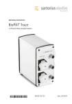
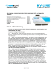
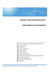
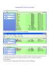
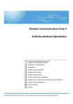
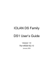
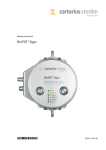
1
Operating Manual BioPAT® Xgas Vis Software Manual 85037-545-79 Contents 1. About This Document . . . . . . . . . . . . . . . . . . . . . . . . . . . . . . . . . . . . . . . . . . . . . . . . . . . . . . . . 4 1.1 Accompanying Documents . . . . . . . . . . . . . . . . . . . . . . . . . . . . . . . . . . . . . . . . . . . . . . 4 1.2 Symbols Used . . . . . . . . . . . . . . . . . . . . . . . . . . . . . . . . . . . . . . . . . . . . . . . . . . . . . . . . . 4 2. Safety Information . . . . . . . . . . . . . . . . . . . . . . . . . . . . . . . . . . . . . . . . . . . . . . . . . . . . . . . . . . 5 2.1 General Safety Precautions . . . . . . . . . . . . . . . . . . . . . . . . . . . . . . . . . . . . . . . . . . . . . . 5 2.2 Intended Use and Foreseeable Misuse . . . . . . . . . . . . . . . . . . . . . . . . . . . . . . . . . . . . . 5 3.Overview . . . . . . . . . . . . . . . . . . . . . . . . . . . . . . . . . . . . . . . . . . . . . . . . . . . . . . . . . . . . . . . . . . . 6 3.1Requirements . . . . . . . . . . . . . . . . . . . . . . . . . . . . . . . . . . . . . . . . . . . . . . . . . . . . . . . . . 6 3.2 Contents of Delivery . . . . . . . . . . . . . . . . . . . . . . . . . . . . . . . . . . . . . . . . . . . . . . . . . . . 6 4.Installation . . . . . . . . . . . . . . . . . . . . . . . . . . . . . . . . . . . . . . . . . . . . . . . . . . . . . . . . . . . . . . . . . 7 4.1 Installation Steps . . . . . . . . . . . . . . . . . . . . . . . . . . . . . . . . . . . . . . . . . . . . . . . . . . . . . . 7 4.2 Hardware Installation . . . . . . . . . . . . . . . . . . . . . . . . . . . . . . . . . . . . . . . . . . . . . . . . . . 8 5. Software Installation . . . . . . . . . . . . . . . . . . . . . . . . . . . . . . . . . . . . . . . . . . . . . . . . . . . . . . . 5.1 Preparation Steps . . . . . . . . . . . . . . . . . . . . . . . . . . . . . . . . . . . . . . . . . . . . . . . . . . . . . 5.2BioPAT® Xgas Vis Software . . . . . . . . . . . . . . . . . . . . . . . . . . . . . . . . . . . . . . . . . . . . . 5.3 Perle Device Driver . . . . . . . . . . . . . . . . . . . . . . . . . . . . . . . . . . . . . . . . . . . . . . . . . . . . 5.4 TruePort Application . . . . . . . . . . . . . . . . . . . . . . . . . . . . . . . . . . . . . . . . . . . . . . . . . . 10 10 15 20 24 6. Hardware Settings . . . . . . . . . . . . . . . . . . . . . . . . . . . . . . . . . . . . . . . . . . . . . . . . . . . . . . . . . 27 6.1 Checking Jumper Settings at the Perle Device . . . . . . . . . . . . . . . . . . . . . . . . . . . . . 27 6.2 Reseting Perle Device . . . . . . . . . . . . . . . . . . . . . . . . . . . . . . . . . . . . . . . . . . . . . . . . . 28 2Contents 7.Configuration . . . . . . . . . . . . . . . . . . . . . . . . . . . . . . . . . . . . . . . . . . . . . . . . . . . . . . . . . . . . . . 7.1 Perle Device . . . . . . . . . . . . . . . . . . . . . . . . . . . . . . . . . . . . . . . . . . . . . . . . . . . . . . . . . 7.2 Serial Port . . . . . . . . . . . . . . . . . . . . . . . . . . . . . . . . . . . . . . . . . . . . . . . . . . . . . . . . . . . 7.2.1 Configuring Serial Port with TruePort Management Tool . . . . . . . . . . . . 7.2.2 Configuring Serial Port with Device Manager . . . . . . . . . . . . . . . . . . . . . 7.3BioPAT® Xgas Vis OPC License . . . . . . . . . . . . . . . . . . . . . . . . . . . . . . . . . . . . . . . . . . . 7.4BioPAT® Xgas Sensor . . . . . . . . . . . . . . . . . . . . . . . . . . . . . . . . . . . . . . . . . . . . . . . . . 7.4.1 Configuring One Sensor . . . . . . . . . . . . . . . . . . . . . . . . . . . . . . . . . . . . . . . 7.4.2 Configuring Multiple Sensors with one Ethernet Modbus Converter . . 7.5 Changing the Modbus Address . . . . . . . . . . . . . . . . . . . . . . . . . . . . . . . . . . . . . . . . . . 29 29 36 36 40 42 44 44 49 50 8. Installation of BioPAT® Xgas OPC Server . . . . . . . . . . . . . . . . . . . . . . . . . . . . . . . . . . . . . . . 8.1 Installing MFCS/win OPC Client . . . . . . . . . . . . . . . . . . . . . . . . . . . . . . . . . . . . . . . . . 8.2 Configuring MFCS/win Configuration Management . . . . . . . . . . . . . . . . . . . . . . . . 8.3 Browsing the BIOPATXGAS.OPC.1 Server with OPC Test Client . . . . . . . . . . . . . . . . 52 53 53 62 9. Firmware Version . . . . . . . . . . . . . . . . . . . . . . . . . . . . . . . . . . . . . . . . . . . . . . . . . . . . . . . . . . . 65 9.1 Checking / Upgrading Firmware Version of the Perle Device . . . . . . . . . . . . . . . . . 65 9.2 Configuring Settings for Windows ModbusService . . . . . . . . . . . . . . . . . . . . . . . . . 69 10.Troubleshooting . . . . . . . . . . . . . . . . . . . . . . . . . . . . . . . . . . . . . . . . . . . . . . . . . . . . . . . . . . . . 71 Contents3 1. About This Document All information and instructions in this operating manual have been compiled in consideration of applicable standards and guidelines, the state of technology and our many years of experience and knowledge. These operating instructions provide you with all the information necessary to install and to configure the BioPAT® Xgas Vis Software. In addition to the operating manual, all generally valid, legal and otherwise binding regulations for accident protection and environmental protection of the country of use must be observed. The operating manual must always be kept at the place of use of the device. 1.1 Accompanying Documents The operating manual describes how to install and to configure the BioPAT® Xgas Vis Software. In addition to these operating instructions, follow the information in the operating manual “BioPAT® Xgas” and in the documentation of the other software and hardware components. 1.2 Symbols Used This symbol - is an indication of a function or setting on the device. - is an indication that caution should be exercised while working. - identifies useful information. The following presentations will also be used: – Texts that follow this mark are lists. t T exts that follow this mark describe activities that must be carried out in the specified order. y Texts that follow this mark describe the result of an action. "" Texts in quotes are references to other chapters or sections. [Æ] Texts following this symbol make reference to other chapters, sections or documents. 4 About This Document 2. Safety Information 2.1 General Safety Precautions The BioPAT® Xgas Vis Software may only be installed and configured after gaining familiarity with this operating manual. Always keep the operating manual in the location where the device is in use. In addition to the operating manual, follow all general and local regulations for accident prevention and environmental protection. 2.2 Intended Use and Foreseeable Misuse The operational safety of the device is only ensured when it is used for its intended purpose and operated by trained personnel. Application The device is only intended for industrial, commercial, training, and research facilities. The BioPAT® Xgas Vis Software is intended for use with the BioPAT® Xgas Sensor and the BioPAT® MFCS/win Software. Safety Information5 3. Overview With the BioPAT® Xgas hardware, the O2 and CO2 concentration can be monitored and controlled for any given bioprocesses in real time. The BioPAT® Xgas is a dual oxygen-carbon dioxide sensor featuring automatic compensation for humidity and pressure. The oxygen concentration can be measured in a range of 1–50 % and the carbon dioxide concentration in a range of 0–10 %. The BioPAT® Xgas Sensor can be directly connected by analog signals to the DCU system. Therefore, only a cable and two free analog input ports at the DCU systems need to be available. Alternatively, if there are no available analog input ports on the DCU system, then it is possible to connect the BioPAT® Xgas hardware using the BioPAT® Xgas Vis Software interfacing to the MFCS/win SCADA software. Herein, the direct connection of the BioPAT® Xgas Sensors to the MFCS/win software with all necessary hardware and software components is described. 3.1 Requirements −− The BioPAT® Xgas Vis Software requires MFCS/win Version 3.0 −− The Firmware version of the used Perle device is minimum 4.5 Computer Configuration General CD ROM drive USB Port Operating System Microsoft Windows XP (32 bit) Microsoft Windows Server 2003 R2 (32 bit & 64 bit) Microsoft Windows 7 (32 bit & 64 bit) Microsoft Windows Server 2008 SP2 (32 bit & 64 bit) Microsoft Windows Server 2008 R2 Sp1 64 bit Operating System Language English, German 3.2 Contents of Delivery The delivery of the BioPAT® Xgas Vis Software contains the following components: −− CD-ROM, containing all necessary software items −− Software activation Dongle −− User Manual for the BioPAT Xgas Vis 6Overview 4. Installation 4.1 Installation Steps The following table presents an overview on the necessary steps to install and configure the BioPAT® Xgas Vis Software. Please follow the recommended order in the table step by step. Each entry refers to a separate chapter or sub-chapter in this handbook where the procedure is described in detail. Step Installation Procedure 0 Hardware installation [Æ 4.2, page 8] 1 Preparation step for installation on Windows XP and Windows Server 2008, only [Æ 5.1, page 10] 2 Software installation of BioPAT® Xgas Vis Software [Æ 5.2, page 15] 3 Installation and configuration of the Perle device driver [Æ 5.3, page 20] 4 Installation of TruePort application [Æ 5.4, page 24] 5 Checking hardware jumper settings at the Perle device [Æ 6.1, page 27] 6 Reset Perle device [Æ 6.2, page 28] 7 Configure Perle device [Æ 7.1, page 29] 8 Configure serial port with TruePort Management Tool [Æ 7.2.1, page 36] 9 Configure serial port with Device Manager [Æ 7.2.2, page 40] 10 Activate the BioPAT® Xgas Vis OPC License [Æ 7.3, page 42] 11 Configuration of one BioPAT® Xgas sensor [Æ 7.4.1, page 44] 12 Configuration of multiple sensors with one Ethernet Modbus Converter [Æ 7.4.2, page 49] 13 How to change the Modbus Address [Æ 7.5, page 50] 14 Installation of BioPAT® Xgas OPC Server [Æ 8, page 52] 15 Installation of MFCS/win OPC Client [Æ 8.1, page 53] Remark Only for Windows XP and Windows Server 2008 Multiple sensors only Installation7 Step Installation Procedure Remark 16 Configuration work inside MFCS/win Configuration Management [Æ 8.2, page 53] 17 How to browse the BIOPATXGA.OPC.1 Server with OPC Test Client [Æ 8.3, page 62] Optional 18 How to check / upgrade the firmware version of the Perle device [Æ 9.1, page 65] Update only necessary, if firmware < 4.5 19 Configure settings for Windows Modbus Service [Æ 9.2, page 69] 4.2 Hardware Installation tt Install the BioPAT® Xgas according the operating manual “BioPAT® Xgas”, delivered together with the BioPAT® Xgas hardware. −− The installation is described in chapter “4. Installation”. As the sensors require a startup heating time of approximately 60 min, it is recommended to do the steps described under “4.3.5 Startup” in an early stage. Connection of BioPAT® Xgas to BioPAT® MFCS/win with BioPAT® Xgas Vis Software 8Installation Accessories The following articles are available for the BioPAT Xgas Vis Software: Article Number Description Remark BPX0009 BioPAT® Xgas Vis Software Can be used with one MFCS/win server system. BPX00(11-15) BioPAT® Xgas Sensor Includes power supply & cable and article number depends on vessel size and corresponding gas flow path. BPX0018 PC connection package (includes Ethernet / Modbus converter and Bus termination) One is needed for each DCU system or independent vessel fitted with BioPAT® Xgas [see figure in chapter Æ 6.2, page 28]. BB-34147295 Serial Modbus Connection cable 2 m One cable (2 m or 5 m) is needed to connect each sequential BioPAT® Xgas unit. BB-34147298 Serial Modbus Connection cable 5 m Installation9 5. Software Installation 5.1 Preparation Steps For Windows XP, only t Start :\DotNetFX35SP1\dotNetFx35setup.exe from the XGAS-CD NET Framework 3.5.1 must be installed manually from the BioPAT Xgas VIS CD. t Open Windows Explorer and browse to the CD into the directory. t Double click the file „:\DotNetFX35SP1\dotNetFx35setup.exe“ 10 Software Installation t Files will be extracted. t Accept the terms and press “Install” button. t Press “Exit” button. t Continue with chapter [Æ 5.2, page 15]. Software Installation11 For Windows Server 2008 R2, only .NET Framework 3.5.1 must be activated for Windows Server 2008. −− Windows Server 2008 includes the necessary .Net framework. Follow the steps below in order to activate the .Net framework. t Go to “Administrative Tools”. t Start the “Server Manager”. t Open “Roles / Features“. t Click “Add Features“. 12 Software Installation t Expand “.NET Framework 3.5.1 Features“. t Select “.NET Framework 3.5.1“. t Click on the “Next“ button. Software Installation13 “Confirm Installation Selection” opens. y t Press button “Install“. y The installation is completed; the installation message “Installation succeeded” is displayed. t Click „Close“ button. 14 Software Installation 5.2 BioPAT® Xgas Vis Software This chapter describes the installation of the BioPAT® Xgas Vis Software. Please consider that MFCS/win must have been already installed. Please note, the installation of this software requires local administrative rights. The CD-ROM containing the BioPAT® Xgas Vis Software is labeled as “BioPAT® Xgas Vis Soft ware”. A separate program named SETUP.EXE performs the software installation. The following steps describe the installation on your computer system. Installing the BioPAT® Xgas Vis Software t Shutdown the MFCS/win system from the MFCS/win Shell. t Insert the CD-ROM into the CD drive. t Open the windows explorer and change to the CD drive. t Double-click on file SETUP.EXE to start the installation program. t If the “.Net Framework 3.5” is not installed, then the following dialog will be shown on the screen. t Press the button “Accept” to continue. Software Installation15 t The welcome screen is shown. t Press button “Next”. t Keep the default settings as shown in the picture. t Press button “Next”. 16 Software Installation t Press button “Next” to install the software in the specified directory. t Press button “Next” to confirm installation. Software Installation17 y The installation progress is shown on the screen. y The message “Installation Complete“ appears. t Press button “Close”. 18 Software Installation , y Restart message appears. t Press button “Yes”. Software Installation19 5.3 Perle Device Driver This chapter describes the installation and configuration of the Perle device driver. t Start the application “\perle iolan\setup.html” from the delivered CD. t Press button “DeviceManager“. If there is a message to “allow blocked content” then enable blocked content. 20 Software Installation t Press link “IOLAN DeviceManager V4.4“ to start Device Manager installation. t Press “Next” button to continue with the installation. Software Installation21 t Use default settings and press “Next” button. Use default settings and press “Next” button. t 22 Software Installation t Use default settings and press “Install” button. Uncheck both topics and press “Finish” button. t Software Installation23 5.4 TruePort Application The following pages describe how to install and configure the TruePort application. t Click on the button “TruePort“ on the left side of the IOLAB Setup. Select the operating system which is installed at your pc. −− For the 32 bit version of the operating system click to “(x86)“. −− For the 64 bit version of the operating system click to “(x64)“. Press “Next“ button to continue. t 24 Software Installation t Keep default settings and press “Next“ button to continue. t Keep default settings and press “Next“ button to continue. Software Installation25 Keep default settings and press button “Install“ to continue. t Uncheck both topics and press “Finish” button. t 26 Software Installation 6. Hardware Settings 6.1 Checking Jumper Settings at the Perle Device 3 1 2 tt Loosen the two screws on the side of the housing to open the Perle device. tt Set the jumpers as specified below: −− Set jumper J1 (1) open −− Set jumper J8 (3) all open −− Set jumper J9 (2) closed tt Close the Perle device and fasten the two screws. Hardware Settings 27 1 tt Set the switch (1) to “OFF” (upper position). yy The perle device is set to serial mode. 6.2 Reseting Perle Device 1 tt Press the “RESET“ button with a paper clip to reset the Perle device. yy After 5 s the lamp “Power/Ready” changes color from green to orange. After “Reset” please wait at least 2 min to let the Perle device finish the reset. 28 Hardware Settings 7. Configuration 7.1 Perle Device Double check, whether the Windows firewall is disabled or the Perle device manager is enabled in the firewall. In Windows firewall open all ports especially for the “devicemanager.exe” (UDP) and for the “tftp_svr.exe” (TCP) or temporarily disable the firewall. For server OS deactivate or stop “DHCPClient” service before starting the configuration. Otherwise the device will receive an IP address automatically. tt Start Perle “Device Manager“. Configuration29 tt Press button “Assign IP”. tt Enter your IP address for the Perle device. tt Press button “Assign IP”. yy The following message is shown. tt Press “OK“ button. 30Configuration Test connection 1 3 2 tt Press “Ping“ (3) button to test connection. tt Close Ping window (2). tt Press “OK” button (1) to connect to Perle device. 1 tt Enter the default password “superuser” (1). tt Press the “OK“ button. Configuration31 tt Open menu “Configuration / Serial / Serial Port”. tt Press “Edit” button. tt Press button “Change Profile”. tt Select option “TruePort” and press “OK“ button. 32Configuration tt Select option “Listen for connection” under tab “General”. tt Press “OK“ button. tt Change to tab “Hardware”. tt Make the selections as shown in the picture. tt Press “OK“ button. Configuration33 tt Press button “Download All Changes”. tt Press button “Yes” to confirm. tt Press “OK” button. 34Configuration 1 2 tt Press button “Reboot IOLAN” (2). tt Close the DeviceManager (1). Configuration35 7.2 Serial Port 7.2.1 Configuring Serial Port with TruePort Management Tool tt Start the “TruePort ManagementTool” to configure the serial port. 1 tt Enter the IP address of the Perle device to the field “IP Address” (1) tt Press “Next“ button. 36Configuration 1 tt Select an available port from the drop down list “Starting COM Port” (1). tt Press “Next“ button. It is recommended to start with COM5, because COM5 will not be used (and therefore available) on most of the systems. Continue with COM6, COM7 if more Perle devices will be connected. tt Press button “Finish”. Configuration37 tt Select the recently configured device and press button “Properties”. tt Change to register card “Configuration”. tt Press button “Settings. 38Configuration tt Select the COM port. tt Activate “Initiate connection to device server”. tt Press button “Settings”. tt Change setting “Delay close of TCP connection for” to 300 seconds. tt Press button “OK“ and close all the remaining windows. Configuration39 7.2.2 Configuring Serial Port with Device Manager 1 2 3 tt Open the Windows “Control panel“. tt Select “Administrative Tools“ (1). tt Select “Computer Management“ (2). tt Select Device Manager (3). 40Configuration 1 2 3 tt Select Ports (COM & LPT) (2). tt Right mouse click to “Trueport Serial Port (COM5)” (2). tt Select “Properties“ (3). tt Change to register card “Port Settings”. tt Perform the settings shown in the picture above. tt Press “OK“ button and close the Windows device manager. Configuration41 7.3 BioPAT® Xgas Vis OPC License This chapter describes how to activate the BioPAT® Xgas Vis OPC License. tt Plug the blue license dongle (SG-Lock) into a free USB port of the MFCS/win computer. The dongle must stay in the USB port all the time if you want to use all features. If the application without the dongle is used, then only the measurement of one analyzer in the BioPAT® Xgas Vis software (without logging) can be used in the Service Tool for the calibration and the changing the MODBUS ID. tt Start the “License Manager“ to activate the BioPAT® Xgas VIS OPC license. 42Configuration 1 tt Select “Sensor Key 3“ (1) from drop down menu. 2 tt Enter the corresponding key in the four input fields (2). tt Press the button “write”. yy The unlocked features and the number of enabled sensors is shown. tt Close the “License Manager“. Configuration43 7.4 BioPAT® Xgas Sensor 7.4.1 Configuring One Sensor tt Start the “Configuration“ tool for BioPAT® Xgas to configure one XGAS Sensor. tt Press the “add” button for interfaces to add a new “Interface”. 44Configuration tt Select −− the correct Interface. −− Baudrate “38400”. −− Parity “none, 2 Stopbits”. tt Press “OK“ button. tt Press the “add” button for sensors to add a new sensor. Configuration45 tt Enter a name ,the Modbus interface and the Modbus ID 1. tt Press the “OK“ button. yy After the sensor has been added, it is shown in the Sensor list. tt If state “ok“ is not shown in the Sensor list, press the “refresh” button to refresh the list. For sensors naming conventions refer to examples on the following pages. 46Configuration 7.4.1.1 Naming conventions for XGAS Sensors Example 1: Only one BioPAT® Xgas Sensor with a BIOSTAT fermentor 1. Sensor Name Modbus Interface Modbus ID Description XGAS1_1 COM5 1 Single Example 2: Two BioPAT® Xgas Sensors with a twin fermentor system Name Modbus Interface Modbus ID Description 1. Sensor XGAS1_1 COM5 1 Twin A 2. Sensor XGAS1_2 COM5 2 Twin B Example 3: Four BioPAT® Xgas Sensors with a B-DCU II 6-fold fermentor system Name Modbus Interface Modbus ID Description 1. Sensor XGAS1_1 COM5 1 B6 A 2. Sensor XGAS1_2 COM5 2 B6 B 3. Sensor XGAS1_3 COM5 3 B6 C 4. Sensor XGAS1_4 COM5 4 B6 D 5. Sensor XGAS1_5 COM5 5 B6 E 6. Sensor XGAS1_6 COM5 6 B6 F Configuration47 Example 4: Nine BioPAT® Xgas Sensors with: −− One BIOSTAT B single fermentor system −− One BIOSTAT B twin fermentor system −− One BIOSTAT B-DCU II 6-fold fermentor system Name Modbus Interface Modbus ID Description 1. Sensor XGAS1_1 COM5 1 Single 2. Sensor XGAS2_1 COM6 1 Twin A 3. Sensor XGAS2_2 COM6 2 Twin B 4. Sensor XGAS3_1 COM7 1 B6 A 5. Sensor XGAS3_2 COM7 2 B6 B 6. Sensor XGAS3_3 COM7 3 B6 C 7. Sensor XGAS3_4 COM7 4 B6 D 8. Sensor XGAS3_5 COM7 5 B6 D 9. Sensor XGAS3_6 COM7 6 B6 D 48Configuration 7.4.2 Configuring Multiple Sensors with one Ethernet Modbus Converter If more than one BioPAT® Xgas Sensor is to be connected to one Perle device (Ethernet Modbus converter), then additional configuration steps are needed, because the default delivery Modbus address of each BioPAT® Xgas Sensor is “1”. tt Please perform the following configuration steps one after each other: Configu- Description ration Step 1 Connect Sensor #1. Verify that it already has Modbus address #1. 2 Label Sensor #1 with the following information: Modbus ID : 1. 3 Disconnect Sensor #1. 4 Connect Sensor #2. Change the Modbus address for #1 to #2. Please refer to chapter [Æ 7.5, page 50]. 5 Label Sensor #2 with the following information: Modbus ID : 2. 6 Disconnect Sensor #2. 7 Connect Sensor #3. Change the Modbus address for #1 to #3. [Æ 7.5, page 50]. 8 Label Sensor #3 with the following information: Modbus ID : 3. 9 Disconnect Sensor #3. Do the same with all the others, which will be connected to the same Perle device. 10 Connect Sensor #n. Change the Modbus address for #1 to#n [Æ 7.5, page 50]. 11 Label Sensor #n with the following information: Modbus ID : n. 12 Disconnect Sensor #n. After the Modbus addresses of all BioPAT® Xgas Sensors has been set correctly, perform the following steps: tt Connect all BioPAT® Xgas Sensors with the delivered Modbus cables. tt Connect the Modbus termination to the last sensor as shown in figure 6-1 [Æ see chapter 4.2, page 8]. Configuration49 7.5 Changing the Modbus Address tt Start the tool “BioPAT Xgas Vis / Tools / Sensor Config“ to change the Modbus address. 1 tt Select the ComPort, where the sensor is connected. tt Check the field (Address Auto). tt Press “Start“ button. tt Wait until the sensor appears (1). tt Press “Stop“ button. tt Select the sensor from the list. tt Press “Configure“ botton. 50Configuration A few seconds after pressing the “Start” button, the message “Searching” must appear in the upper left corner of the “Sensor Config” window. −− If this message is not shown, press “Start” button again. tt Enter the new address for the sensor. tt Press “OK“ button. yy The success message is shown. yy Press “OK“ button. Configuration51 8. Installation of BioPAT® Xgas OPC Server Start the program “install OPC server” to install the BioPAT® Xgas OPC Server. tt Open “BioPAT® Xgas Vis / tools menu / install OPC server”. tt Press button “OK” to finish the installation. 52 Installation of BioPAT® Xgas OPC Server 8.1 Installing MFCS/win OPC Client If the MFCS/win OPC DA Client is already installed, then continue with next chapter. tt If the MFCS/win OPC DA Client is not installed, install the MFCS/win OPC DA Client according the delivered documentation “MFCS/win OPC DA Client Handbook (MFCSOPCC)”. 8.2 Configuring MFCS/win Configuration Management Inside the MFCS/win SCADA software first a control unit of type “OPC” must be configured. Then the variables for O2 and CO2 of the different fermentors must be configured. tt Start MFCS/win Shell. tt Start “Configuration Management“. Installation of BioPAT® Xgas OPC Server53 tt Select “Configure / Control Units“. 1 2 3 4 tt Create a new Control Unit of type “OPC” and enter a name (e.g. Xgas1): −− Press “New“ button (4). −− Select Control Unit name (1). −− Select type „OPC“ (2). −− Press button “Parameter“ (3). 54 Installation of BioPAT® Xgas OPC Server 1 2 tt Select the “BioPatXgas.OPC.1” server from the drop down list (1) and confirm (2). tt Create a new cyclic variable “CO2”. tt Create a new cyclic variable “O2”. Installation of BioPAT® Xgas OPC Server55 tt Select control unit “XGAS1”. tt For CO2 configure the range 0-10 % tt For O2 configure the range 1-50 %. tt Press “Driver“ button. yy The “OPC Item Configuration“ opens (see following picture). 56 Installation of BioPAT® Xgas OPC Server tt If the sensor name is “XGAS1_1”, enter the OPC Tag “XGAS1_1.Values.CO2”. tt Confirm with “OK“ button. tt If the sensor name is “XGAS1_1”, enter the OPC Tag “XGAS1_1.Values.O2”. tt Confirm with “OK“ button. Installation of BioPAT® Xgas OPC Server57 Sensor name 1 The sensor name (1) can be looked up in the Sensor configuration as described in chapter [Æ 7.4, page 44]. Instead of directly filling in the OPC Tags, an OPC Test Client can be used to browse and then the OPC tags can be filled in with copy & paste. −− Refer to chapter [Æ 8.3, page 62]. 58 Installation of BioPAT® Xgas OPC Server Adding new variables to Storage list After the interface configuration is finished, the new variables must be added to the Storage list. tt Add the new variables O2 and CO2 to the Storage list as shown on the picture above. tt Perform “Update Configuration” from the “MFCS/win Shell to finalize the tt MFCS/win configuration“. Installation of BioPAT® Xgas OPC Server59 Fig. 10-1: Verification of the communication between MFCS/win and BioPAT® Xgas from the MFCS/win Operator Service Program 60 Installation of BioPAT® Xgas OPC Server Fig. 10-2: Verification of the communication between MFCS/win and BioPAT® Xgas with the MFCS/win Plotting Installation of BioPAT® Xgas OPC Server61 8.3 Browsing the BIOPATXGAS.OPC.1 Server with OPC Test Client tt Copy the tool “OPC_Client.exe“ to the MFCS/win server computer into directory “:\MFCS_ win\Tasks\OPC\“. −− This tool is available at the BioPAT MFCS/win OPC DA Client CD in directory ”<CD-ROM>:\ SupportTools”. tt Start the file “OPC_Client.EXE“ at the MFCS/win Server computer. yy Now the connection to the OPC server can be done, by doing the following steps. tt Connect to OPC Server with “OPC / Connect”. 62 Installation of BioPAT® Xgas OPC Server tt Select the “BioPatXgas.OPC.1“ server from the list. After the Test Client is connected to the BioPATXgas.OPC.1 server, add items. tt Click “OPC / Add Item...“. Installation of BioPAT® Xgas OPC Server63 tt Browse for O2 and CO2. tt Click “Add Item “. If the CO2 variable is selected in the list, then the OPC Tag will be shown in the field “Item Name”. This OPC Tag can be transferred with cut & paste to the MFCS/win configuration as shown in section [Æ page 58]. O2 and CO2 values in OPC Test Client: 64 Installation of BioPAT® Xgas OPC Server 9. Firmware Version 9.1 Checking / Upgrading Firmware Version of the Perle Device For trouble free operation it is necessary, that the firmware version 4.5 is available in the Perle device. How to check the installed firmware version of the Perle device is described in this chapter. tt Start the “TruePort ManagementTool” for verification. tt Select the Perle TruePort Adapter in question. tt Press the “Properties” button. Firmware Version65 tt Change to register card “Configuration”. tt Press button “Web Config”. 66 Firmware Version 1 2 Enter username “admin” (1) and password “superuser” (2). tt tt Press button “Login”. yy Informations about the used Perle device are shown on the right side including the installed firmware version. Firmware Version67 Updating firmware tt If the installed firmware is below version 4.5, upgrade the firmware version of the Perle device. −− The newest firmware version can always be downloaded from the internet www.perle.com/downloads. How the firmware will be installed at the Perle device is described in chapter “Downloading IOLAN Firmware” on page 348 in the manual “IOLAN_SCS-SDS-STS_UG_v4.4.pdf”, available on the BioPAT® Xgas VIS CD. 68 Firmware Version 9.2 Configuring Settings for Windows ModbusService tt Open “Windows Control Panel / All Control Panel Items / Administrative Tools“. tt Double click “Services”. Firmware Version69 tt Scroll down the list until “ModbusService” appears in the list. tt Double click “ModbusService” and select register card “Recovery”. tt Select the setting “Restart the Service” from the drop down list for the three items “First failure”, “Second failure” and “Subsequent failure”. 70 Firmware Version 10.Troubleshooting If you cannot correct a fault independently, contact: Sartorius Stedim Systems GmbH Robert-Bosch-Str. 5-7 D-34302 Guxhagen Tel. +49 (5665) 407-0 http://www.sartorius-stedim.com e-mail: [email protected] Troubleshooting71 Sartorius Stedim Systems GmbH Robert-Bosch-Strasse 5–7 D-34302 Guxhagen, Germany Phone +49 (0) 5665-407-0 Fax +49 (0) 5665-407-2200 www.sartorius-stedim.com Copyright by Sartorius, Guxhagen, Germany. No part of this publication may be reprinted or translated in any form or by any means without the prior written permission of Sartorius. All rights reserved by Sartorius in accordance with copyright law. The information and figures contained in these instructions correspond to the version date specified below. Sartorius reserves the right to make changes to the technology, features, specifications and design of the equipment without notice. Status: July 2014 Sartorius Stedim Systems GmbH, Guxhagen, Germany. Printed in the EU on paper bleached without chlorine. | NT Publication No.: SBI6018-e140701