1
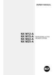
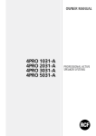
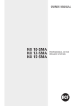
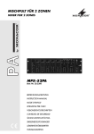
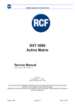
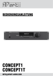
OWNER MANUAL
PR4092
9 INPUTS - 2 OUTPUTS
PA PREAMPLIFIER
ENGLISH
LANGUAGE
ENGLISH
ITALIANO
DEUTSCH
2
3
12
21
ENGLISH
SAFETY
PRECAUTIONS
Before connecting and using this product, please read this instruction manual carefully and
keep it on hand for future reference. The manual is to be considered an integral part of
this product and must accompany it when it changes ownership as a reference for correct
installation and use as well as for the safety precautions.
RCF S.p.A. will not assume any responsibility for the incorrect installation and / or use of
this product.
IMPORTANT NOTES
WARNING: To prevent the risk of fire or electric shock, never expose this product to rain or
humidity (except in case it has been expressly designed and made for outdoor use).
WARNING
SAFETY PRECAUTIONS
1. All the precautions, in particular the safety ones, must be read with special attention, as
they provide important information.
2.1 Power supply from mains (direct connection)
a. The mains voltage is sufficiently high to involve a risk of electrocution; therefore, never
install or connect this product with the power supply switched on.
b. Before powering up, make sure that all the connections have been made correctly and
the voltage of your mains corresponds to the voltage shown on the rating plate on the
unit, if not, please contact your RCF dealer.
c. The metallic parts of the unit are earthed by means of the power cable. In the event
that the current outlet used for power does not provide the earth connection, contact
a qualified electrician to earth this product by using the dedicated terminal.
d. Protect the power cable from damage; make sure it is positioned in a way that it
cannot be stepped on or crushed by objects.
e. To prevent the risk of electric shock, never open the product: there are no parts inside
that the user needs to access.
2.2 Power supply by means of an external adapter
a. Use the dedicated adapter only; verify the mains voltage corresponds to the voltage
shown on the adapter rating plate and the adapter output voltage value and type
(direct / alternating) corresponds to the product input voltage, if not, please contact
your RCF dealer; verify also that the adapter hasn’t been damaged due to possible
clashes / hits or overloads.
b. The mains voltage, which the adapter is connected to, is sufficiently high to involve
a risk of electrocution: pay attention during the connection (i.e. never do it with wet
hands) and never open the adapter.
c. Make sure that the adapter cable is not (or cannot be) stepped on or crushed by other
objects (pay particular attention to the cable part near the plug and the point where
it leads out from the adapter).
3. Make sure that no objects or liquids can get into this product, as this may cause a short
circuit.
4. Never attempt to carry out any operations, modifications or repairs that are not expressly
described in this manual.
Contact your authorized service centre or qualified personnel should any of the following
occur:
-- the product does not function (or functions in an anomalous way);
-- the power supply cable has been damaged;
-- objects or liquids have got into the unit;
-- the product has been subject to a heavy impact.
5. If this product is not used for a long period, switch it off and disconnect the power cable.
6. If this product begins emitting any strange odours or smoke, switch it off immediately
and disconnect the power supply cable.
3
ENGLISH
7. Do not connect this product to any equipment or accessories not foreseen.
For suspended installation, only use the dedicated anchoring points and do not try to hang
this product by using elements that are unsuitable or not specific for this purpose.
Also check the suitability of the support surface to which the product is anchored (wall,
ceiling, structure, etc.), and the components used for attachment (screw anchors, screws,
brackets not supplied by RCF etc.), which must guarantee the security of the system /
installation over time, also considering, for example, the mechanical vibrations normally
generated by transducers.
To prevent the risk of falling equipment, do not stack multiple units of this product unless
this possibility is specified in the instruction manual.
8. RCF S.p.A. strongly recommends this product is only installed by professional
qualified installers (or specialised firms) who can ensure correct installation
and certify it according to the regulations in force.
The entire audio system must comply with the current standards and regulations
regarding electrical systems.
9. Supports and trolleys
The equipment should be only used on trolleys or supports, where necessary, that are
recommended by the manufacturer. The equipment / support / trolley assembly must be
moved with extreme caution. Sudden stops, excessive pushing force and uneven floors may
cause the assembly to overturn.
10. There are numerous mechanical and electrical factors to be considered when installing
a professional audio system (in addition to those which are strictly acoustic, such as sound
pressure, angles of coverage, frequency response, etc.).
11. Hearing loss
Exposure to high sound levels can cause permanent hearing loss. The acoustic pressure
level that leads to hearing loss is different from person to person and depends on the
duration of exposure. To prevent potentially dangerous exposure to high levels of acoustic
pressure, anyone who is exposed to these levels should use adequate protection devices.
When a transducer capable of producing high sound levels is being used, it is therefore
necessary to wear ear plugs or protective earphones.
See the technical specifications in the instruction manual for the maximum sound pressure
the loudspeaker is capable of producing.
IMPORTANT NOTES
To prevent the occurrence of noise on the cables that carry microphone signals or line
signals (for example, 0 dB), only use screened cables and avoid running running them in
the vicinity of:
-- equipment that produces high-intensity electromagnetic fields (for example, high power
transformers);
-- mains cables;
-- lines that supply loudspeakers.
OPERATING PRECAUTIONS
-- Do not obstruct the ventilation grilles of the unit. Situate this product far from any heat
sources and always ensure adequate air circulation around the ventilation grilles.
-- Do not overload this product for extended periods of time.
-- Never force the control elements (keys, knobs, etc. ).
-- Do not use solvents, alcohol, benzene or other volatile substances for cleaning the
external parts of this product.
4
IMPORTANT NOTES
ENGLISH
PRODUCT
INFORMATIONS
RCF S.p.A. would like to thank you for having purchased this product, which
has been designed to guarantee reliability and high performance.
The PR 4092 preamplifier has been specifically designed for the public broadcasting of
announcements and/or musical programs in all audio systems. Each of the 9 inputs can
be sent to output “A” only, to output “B” only, or to both. The equipment can therefore
be used as a double preamplifier (for example: output “A” reserved for microphone
announcements; output “B” reserved for background music). Input no. 1 has absolute
priority (activated both by means of a contact and by the presence of a signal); inputs nos. 2
and 3 can be given priority over the subsequent inputs; an input’s priority function is active
only at the output selected (or both).
-- 1 microphone input (no. 1; XLR connector) with absolute priority activated both (auto)
in the presence of a signal (VOX) and by contact; signal indicator (LED)
-- 8 universal inputs, each with MIC / LINE selector and signal indicator (LED), located on
the front panel:
inputs nos. 2, 3, 4, and 5, with XLR connector (MIC / LINE)
inputs nos. 6, 7, 8 and 9, with XLR connector (MIC) and double RCA (LINE)
-- “Phantom” feed (can be inactivated by group) at the microphone inputs - 2 balanced
outputs with XLR connector - double “REC” output (double RCA connector)
-- inputs 2 and 3 given priority over subsequent inputs by means of vocal activation
(excludable)
-- warning signal (3-tone) activated by means of contact (input 1) or the “CHIME TEST”
button the front panel - level control (with VU meter) for each of the two outputs
-- bass- and treble-tone control for each output
-- alternating-current power supply (230 V - 50 Hz / 115 V - 60 Hz)
-- direct current power supply (24 V).
MAIN CHARACTERISTICS
FRONT PANEL
1
2
5
4
7
8
6
3
1 CHIME. Pressing the “CHIME TEST” button sends a warning signal (3-tone) to the output
selected, making it possible to regulate its level by means of the relative volume control.
2 VOLUME CONTROL (CHIME, INPUTS 1÷9). Makes it possible to set the signal level of
the relative input. Note: the level must be regulated so that the signal is optimal at the
output selected but without the peak indicator (read LED “PEAK”) lighting up.
5
ENGLISH
3 OUTPUT SELECTOR (CHIME, INPUTS 1÷9). Makes it possible to direct the signal to
output “A” only, to output “B” only, or to both. Note: the priority function (inputs 1, 2
and 3) is active only at the output selected. When a priority is active, it could happen that
sources assigned to one output are present at lower level on the other output as well.
4 SIGNAL-PRESENCE INDICATOR (GREEN LED; INPUTS 1÷9). Lights up in the presence
of an input signal.
5 MIC / LINE LEVEL SELECTOR (INPUTS 2÷9). The selector has 3 positions:
- MIC: microphone signal with high-pass filter inserted (cut-off frequency: 300 Hz)
- MIC: microphone signal
- LINE: high-level signal (CD player, cassette deck, radio tuner).
Note:
- the “MIC” positions activate the PHANTOM feed to the microphone inputs (with XLR
connector), to which it is advisable to connect only microphones (electret, condenser, etc.)
that need this feed. If dynamic microphones are used, it is necessary for the cable to be
balanced in order to avoid possible malfunctioning and/or damage to the microphones.
Alternatively, the PHANTOM feed can be removed from some of the inputs by using the
internal jumpers (JP3 - JP6).
- the level selector also enables the connector (to be used) of the 6÷9 inputs: XLR in the
2 MIC positions: double RCA in the “LINE” position.
6 “PRIORITY” BUTTON (INPUTS 2 AND 3). When pressed, it enables the vocal-activation
priority of inputs 2 and 3 (note: the presence of any signal at inputs 2 and 3 activates the
priority function).
7 AUDIO-OUTPUT CONTROLS. Each output has the following controls:
- a volume control;
- a bass-tone control (100 Hz);
- a treble-tone control (10 kHz);
- a VU METER consisting of 5 LEDs (corresponding to these levels: -20 dBu, -10 dBu,
-3 dBu, 0 dBu, “peak”).
8 “POWER” ON/OFF BUTTON WITH LIGHT (GREEN LED) “ON”. Turns the equipment on
and off.
REAR
PANEL
9
10
11
12
13
14
9 POWER-SUPPLY CABLE PLUG (230-115 V AC) WITH FUSE. For connecting the power
cable supplied.
10 24-V DC FEED CLAMPS. The 2 clamps make it possible to power the preamplifier with
direct current from an external source (batteries, for example). If the usual power supply is
unavailable or suddenly cuts out, the equipment can be powered with direct current, thus
ensuring continuous operation.
11 MAIN AUDIO OUTPUTS “A” AND “B”. Balanced audio outputs with XLR connectors.
6
15
16
ENGLISH
12 AUDIO OUTPUTS “REC” “A” AND“B”. Outputs (unbalanced, with RCA connectors) for
connecting a recording device (or other device).
Note: the signal level is not regulated by the main outputs’ volume controls.
13 HIGH-LEVEL (“LINE”) AUDIO INPUTS 6÷9. Double-line inputs (RCA connectors for
stereo music sources) with -10dBu (245 mV) sensitivity. The right and left channels are
combined, resulting in a single mono signal that can be directed to one or both the audio
outputs.
14 MICROPHONE AUDIO INPUTS 6÷9. Balanced audio inputs for microphones (XLR
connectors).
15 Audio inputs 2÷5. Balanced audio inputs (XLR connectors). The “MIC / LINE” level
can be selected with the relative switches on the front panel.
16 Single microphone audio input for announcements; controls. Balanced
audio input (XLR connector) for announcement microphone, with terminal board having
the following commands:
- CHIME: if grounded, activates the warning signals;
- PRIORITY: if grounded, gives absolute priority to input 1;
- GROUND: earth; - VDC LED: feed output for an LED.
INSTALLATION
- Do not set up the equipment in places subject to high-intensity vibrations or particularly
exposed to dust or humidity.
- The container rack must conform to the EN 60439-1 standard; in particular, the back must
be closed with appropriate panels.
CONNECTIONS
To avoid inductive phenomena that might give rise to hum or other disturbances and
compromise the equipment’s proper functioning, the connection cables that carry the audio
signals must not be near:
1) equipment that produces strong magnetic fields (large power-supply transformers, for
example);
2) electric-energy conductors;
3) lines that feed diffusers.
DC POWER SUPPLY
WARNING: When the equipment is fed with direct current, do not disconnect the
powersupply cord. This is in order to keep the equipment grounded. The equipment is not
equipped with a device for recharging batteries. An appropriate device should therefore be
considered.
WARNING
7
SPECIFICATIONS
INPUTS
Sensitivity, Impedance
Phantom Power
OUTPUTS
Voltage, Impedance
FREQUENCY RESPONSE
12 V, 10 mA
MASTER 1,2: nor. +4 dBu (1,23 V), 200 Ω balanced
REC: nor. 0 dBu (775 mV), 2.2 KΩ unbalanced
20 ÷ 20’000 Hz
SIGNAL/NOISE AND CROSSTALK
MIC: > 60 dB
DIAPHONIA
LINE: > 75 dB
DISTORTION (T.H.D.)
MIC: < 0,5 %
LINE: < 0,3 %
CONTROLS
TONE CONTROLS
FEED, CONSUMPTION
MAXIMUM 24-V ABSORPTION
MAXIMUM AMBIENT TEMPERATURE
DIMENSIONS
WEIGHT
8
MIC (XLR): - 50 dBu (2,45 mV), 5 kΩ balanced
LINE (XLR): -10 dBu (245 mV), 5 kΩ balanced
LINE (RCA): -10 dBu (245 mV), 10 kΩ unbalanced
9 volume controls per input - 1 “CHIME” volume
control - 2 general volume controls - 2 bass-tone
controls - 2 treble-tone controls
BASS: 100 Hz ± 10 dB
TREBLE: 10 kHz ± 10 dB
230 V - 50 Hz / 115 V - 60 Hz, 10 VA
(alternating current)
450 mA (direct-current)
55° C
483 x 44 x 200 mm (1 rack unit)
3.9 kg
ENGLISH
SECTION RESERVED
FOR RCF SERVICE
CENTERS
WARNING: The operations described in this section are intended exclusively RCF S.p.A.
SERVICE CENTERS. The following information DOES NOT CONCERN THE USER, who may
omit reading.
Before carrying out the operations described in this section, the power-supply
must be disconnected from the direct-current power source.
WARNING
Voltage selector is under a cover on the bottom of the device. Pls remove screw and select
right voltage according to the AC mains.
FEED-VOLTAGE SELECTION
The MAIN CHART (found inside the preamplifier) shows the jumpers that the selection
of some of the equipment’s operating modes. The function of each jumper is given in the
following table.
INTERNAL JUMPER CONFIGURATION
NAME
“ON” POSITION
(jumper short-circuited)
“OFF” POSITION
(jumper open)
JP 1
CHIME MUTE ON
THE WARNING SIGNAL
(“CHIME”) HAS PRIORITY ON
INPUTS 2÷9
THE WARNING SIGNAL DOES
NOT HAVE PRIORITY BUT IS
MIXED WITH ALL
JP 2
IN 1 MUTE
INPUT 1 HAS AUTOMATIC
PRIORITY IN THE PRESENCE OF A
SIGNAL (VOX)
INPUT 1 DOES NOT HAVE
AUTOMATIC PRIORITY (Note:
priority may, however, be
activated by means of a remote
contact connected to the
“priority” and “ground” clamps)
JP 3
IN 2 PHANTOM
PHANTOM FEED
AT INPUT 2
NO PHANTOM FEED
AT INPUT 2
JP 4
IN 3 PHANTOM
PHANTOM FEED
AT INPUT 3
NO PHANTOM FEED
AT INPUT 3
JP 5
IN 4-5 PHANTOM
PHANTOM FEED
AT INPUTS 4, 5
NO PHANTOM FEED
INPUTS 4, 5
JP 6
IN 6÷9 PHANTOM
PHANTOM FEED
AT INPUTS 6÷9
NO PHANTOM FEED
AT INPUT 6÷9
9
ENGLISH
Balanced Signal
Input
HOT
COLD
GND
3 - pin XLR socket
Connection to the XLR socket (balanced signal).
Do not turn Phantom Power on.
Unbalanced Signal
Input
GND
3 - pin XLR socket
Connection to the XLR socket (unbalanced signal).
Do not turn Phantom Power on.
Audio Signal (right or left channel)
GND
RCA plug
Connection of the RCA plugs.
HOT
COLD
Output
Connection to the main audio outputs (XLR plug, balanced signal.
10
GND
Balanced signal
ENGLISH
CHIME
PRIO
GND
VDC
LED
CHIME activation by means of contact.
Input 1 priority activation by means of contact.
CHIME
PRIO
GND
VDC
LED
LED feed.
11
ITALIANO
AVVERTENZE PER
LA SICUREZZA
Prima di collegare ed utilizzare questo prodotto, leggere attentamente le istruzioni
contenute in questo manuale, il quale è da conservare per riferimenti futuri. Il presente
manuale costituisce parte integrante del prodotto e deve accompagnare quest’ultimo
anche nei passaggi di proprietà, per permettere al nuovo proprietario di conoscere le
modalità d’installazione e d’utilizzo e le avvertenze per la sicurezza.
L’installazione e l’utilizzo errati del prodotto esimono la RCF S.p.A. da ogni responsabilità.
IMPORTANTE
ATTENZIONE: Per prevenire i rischi di fiamme o scosse elettriche, non esporre mai questo
prodotto alla pioggia o all’umidità (salvo il caso in cui sia stato espressamente progettato
e costruito per l’uso all’aperto).
ATTENZIONE
AVVERTENZE PER LA SICUREZZA
1. Tutte le avvertenze, in particolare quelle relative alla sicurezza, devono essere lette con
particolare attenzione, in quanto contengono importanti informazioni.
2.1 Alimentazione diretta da rete
a. La tensione di alimentazione dell’apparecchio ha un valore sufficientemente alto da
costituire un rischio di folgorazione per le persone: non procedere mai all’installazione
o connessione dell’apparecchio con l’alimentazione inserita.
b. Prima di alimentare questo prodotto, assicurarsi che tutte le connessioni siano corrette
e che la tensione della vostra rete di alimentazione corrisponda quella di targa
dell’apparecchio, in caso contrario rivolgetevi ad un rivenditore RCF.
c. Le parti metalliche dell’apparecchio sono collegate a terra tramite il cavo di
alimentazione. Nel caso la presa di corrente utilizzata per l’alimentazione non fornisca
il collegamento con la terra, contattare un elettricista qualificato, che provvederà a
connettere a terra l’apparecchio tramite l’apposito morsetto.
d. Accertarsi che il cavo di alimentazione dell’apparecchio non possa essere calpestato o
schiacciato da oggetti, al fine di salvaguardarne la perfetta integrità.
e. Per evitare il rischio di shock elettrici, non aprire mai l’apparecchio: all’interno non vi
sono parti che possono essere utilizzate dall’utente.
2.2 Alimentazione tramite alimentatore esterno
a. Alimentare il prodotto utilizzando solo l’alimentatore dedicato; verificare che la
tensione della vostra rete corrisponda quella di targa dell’alimentatore e che il valore
ed il tipo (continua o alternata) di tensione d’uscita dello stesso corrisponda a quella
d’ingresso del prodotto, in caso contrario rivolgersi ad un rivenditore RCF; verificare
inoltre che l’alimentatore non sia stato danneggiato da eventuali urti o sovraccarichi.
b. La tensione di rete, alla quale è connesso l’alimentatore, ha un valore sufficientemente
alto da costituire un rischio di folgorazione per le persone: prestare attenzione durante
la connessione alla rete (es. non effettuarla con le mani bagnate) e non aprire mai
l’alimentatore.
c. Accertarsi che il cavo dell’alimentatore non sia o possa essere schiacciato da altri
oggetti (prestando particolare attenzione alla parte del cavo vicino alla spina ed al
punto dove questo esce dall’alimentatore).
3. Impedire che oggetti o liquidi entrino all’interno del prodotto, perché potrebbero causare
un corto circuito.
4. Non eseguire sul prodotto interventi / modifiche / riparazioni se non quelle espressamente
descritte sul manuale istruzioni.
Contattare centri di assistenza autorizzati o personale altamente qualificato quando:
-- l’apparecchio non funziona (o funziona in modo anomalo);
-- il cavo di alimentazione ha subito gravi danni;
-- oggetti o liquidi sono entrati nell’apparecchio;
-- l’apparecchio ha subito forti urti.
5. Qualora questo prodotto non sia utilizzato per lunghi periodi, togliere la tensione dal
cavo di alimentazione (o scollegare l’alimentatore esterno).
12
ITALIANO
6. Nel caso che dal prodotto provengano odori anomali o fumo, spegnerlo immediatamente
e togliere la tensione dal cavo di alimentazione (o scollegare l’alimentatore esterno).
7. Non collegare a questo prodotto altri apparecchi e accessori non previsti.
Quando è prevista l’installazione sospesa, utilizzare solamente gli appositi punti di
ancoraggio e non cercare di appendere questo prodotto tramite elementi non idonei o
previsti allo scopo. Verificare inoltre l’idoneità del supporto (parete, soffitto, struttura ecc., al
quale è ancorato il prodotto) e dei componenti utilizzati per il fissaggio (tasselli, viti, staffe
non fornite da RCF ecc.) che devono garantire la sicurezza dell’impianto / installazione
nel tempo, anche considerando, ad esempio, vibrazioni meccaniche normalmente generate
da un trasduttore. Per evitare il pericolo di cadute, non sovrapporre fra loro più unità di
questo prodotto, quando questa possibilità non è espressamente contemplata dal manuale
istruzioni.
8. La RCF S.p.A. raccomanda vivamente che l’installazione di questo prodotto
sia eseguita solamente da installatori professionali qualificati (oppure da ditte
specializzate) in grado di farla correttamente e certificarla in accordo con le
normative vigenti. Tutto il sistema audio dovrà essere in conformità con le
norme e le leggi vigenti in materia di impianti elettrici.
9. Sostegni e carrelli
Se previsto, il prodotto va utilizzato solo su carrelli o sostegni consigliati dal produttore.
L’insieme apparecchio-sostegno / carrello va mosso con estrema cura. Arresti improvvisi,
spinte eccessive e superfici irregolari o inclinate possono provocare il ribaltamento
dell’assieme.
10. Vi sono numerosi fattori meccanici ed elettrici da considerare quando si installa un
sistema audio professionale (oltre a quelli prettamente acustici, come la pressione sonora,
gli angoli di copertura, la risposta in frequenza, ecc.).
11. Perdita dell’udito
L’esposizione ad elevati livelli sonori può provocare la perdita permanente dell’udito. Il
livello di pressione acustica pericolosa per l’udito varia sensibilmente da persona a
persona e dipende dalla durata dell’esposizione. Per evitare un’esposizione potenzialmente
pericolosa ad elevati livelli di pressione acustica, è necessario che chiunque sia sottoposto
a tali livelli utilizzi delle adeguate protezioni; quando si fa funzionare un trasduttore in
grado di produrre elevati livelli sonori è necessario indossare dei tappi per orecchie o delle
cuffie protettive. Consultare i dati tecnici contenuti nel manuale istruzioni per conoscere la
massima pressione sonora che il diffusore acustico è in grado di produrre.
NOTE IMPORTANTI
Per evitare fenomeni di rumorosità indotta sui cavi che trasportano segnali dai microfoni o
di linea (per esempio 0dB), usare solo cavi schermati ed evitare di posarli nelle vicinanze di:
-- apparecchiature che producono campi elettromagnetici di forte intensità
-- (per esempio trasformatori di grande di potenza);
-- cavi di rete;
-- linee che alimentano altoparlanti.
NOTE IMPORTANTI
PRECAUZIONI D’USO
-- Non ostruire le griglie di ventilazione dell’unità. Collocare il prodotto lontano da fonti
di calore e garantire la circolazione dell’aria in corrispondenza delle griglie di aerazione.
-- Non sovraccaricare questo prodotto per lunghi periodi.
-- Non forzare mai gli organi di comando (tasti, manopole ecc.).
-- Non usare solventi, alcool, benzina o altre sostanze volatili per la pulitura delle parti
esterne dell’unità.
13
ITALIANO
DESCRIZIONE
GENERALE
RCF S.p.A. Vi ringrazia per l’acquisto di questo prodotto, realizzato in modo
da garantirne l’affidabilità e prestazioni elevate.
Il preamplificatore PR 4092 è stato espressamente studiato per la diffusione di annunci
e/o programmi musicali in tutti i sistemi audio ad indirizzo pubblico. Ciascuno dei 9 ingressi
può essere inviato solo all’uscita “A”, solo all’uscita “B” o ad entrambe, permettendo così
un utilizzo dell’apparecchiatura come doppio preamplificatore (esempio: uscita A riservata
agli annunci microfonici; uscita B riservata alla musica di sottofondo). L’ingresso nr.1 ha
la priorità assoluta (attivabile sia tramite un contatto, sia con la presenza del segnale); gli
ingressi nr.2, 3 possono essere resi prioritari su quelli successivi; la funzione di priorità di un
ingresso è attiva solo sull’uscita selezionata (o entrambe).
-- 1 ingresso microfonico (nr.1; connettore XLR) con priorità assoluta attivabile sia (aut.) in
presenza di segnale (VOX), sia tramite contatto; indicatore (LED) di segnale
-- 8 ingressi universali, ciascuno con selettore MIC / LINE ed indicatore (LED) di segnale
posti sul pannello frontale:
ingressi nr. 2,3,4,5 con connettore XLR (MIC / LINEA)
ingressi nr. 6,7,8,9 con connettore XLR (MIC) e doppio RCA (LINEA)
-- alimentazione “Phantom” (disattivabile a gruppi) presente agli ingressi microfonici
-- 2 uscite bilanciate con connettore XLR
-- doppia uscita “REC” (doppio connettore RCA)
-- priorità degli ingressi 2 e 3 su quelli successivi tramite attivazione vocale (escludibile)
-- segnale di preavviso (3 toni) attivabile tramite contatto (ingresso 1) o pulsante “CHIME
TEST” sul pannello frontale
-- controllo di livello (con VU meter) per ciascuna delle 2 uscite
-- controllo toni bassi e alti per ciascuna uscita
-- alimentazione in corrente alternata (230 V - 50 Hz / 115 V - 60 Hz )
-- alimentazione in corrente continua (24 V)
CARATTERISTICHE PRINCIPALI
PANNELLO
FRONTALE
1
2
5
6
3
1 CHIME. Premendo il pulsante “CHIME TEST” si invia il segnale di preavviso (3 toni)
verso l’uscita selezionata, permettendo di regolarne il livello tramite il relativo controllo di
volume.
2 Controllo di volume (chime, ingressi 1 ÷ 9). Permette di impostare il livello del
segnale del relativo ingresso. Nota: occorre regolarlo in modo che il livello del segnale sia
ottimale sull’uscita selezionata, ma non si accenda l’indicatore di picco (LED rosso“PEAK”).
14
4
7
8
ITALIANO
3 SELETTORE USCITA (CHIME, INGRESSI 1 ÷ 9). Permette di indirizzare il segnale solo
verso l’uscita “A”, solo l’uscita “B” od entrambe. Nota: la funzione priorità (ingressi 1,2,3)
è attiva solo sull’uscita selezionata. Può accadere che sorgenti assegnate ad una uscita
siano presenti con segnale residuo sull’altra uscita quando è attiva una priorità.
4 INDICATORE PRESENZA DI SEGNALE (LED VERDE; INGRESSI 1 ÷ 9). Si accende in
presenza di segnale all’ingresso.
5 Selettore livello mic. / line (ingressi 2 ÷ 9). Il selettore presenta 3 posizioni:
- MIC segnale microfonico con filtro passa-alto inserito (freq. di taglio: 300 Hz)
- MIC segnale microfonico
- LINE segnale ad alto livello (lettori CD, cassette, sintonizzatori radio)
Note:
- le posizioni “MIC” attivano l’alimentazione PHANTOM sugli ingressi microfonici (con
connettore XLR), ai quali è consigliabile connettere solo microfoni che necessitano di tale
alimentazione (ad elettrete, a condensatore). Nel caso si utilizzino microfoni dinamici,
è necessario che il cavo sia bilanciato per evitare possibili malfunzionamenti e danni ai
microfoni stessi, oppure è possibile togliere l’alimentazione PHANTOM ad alcuni ingressi
tramite l’impostazione dei ponticelli (jumpers JP3 ÷ JP6) interni.
- il selettore di livello abilita anche il connettore (da utilizzarsi) degli ingressi 6 ÷ 9: XLR
nelle 2 posizioni “MIC”; doppio RCA nella posizione “LINE”.
6 Tasto “PRIORITY” (ingressi 2 e 3). Se premuto, abilita la priorità ad attivazione vocale
degli ingressi 2 e 3 (nota: la presenza di un qualsiasi segnale agli ingressi 2 o 3 attiva la
funzione di priorità)
7 Controlli uscite audio. Sono presenti (per ciascuna uscita):
- un controllo di volume;
- un controllo toni bassi (100 Hz);
- un controllo toni alti (10 kHz)
- un VU METER composto da 5 LED (corrispondenti ai livelli: -20 dBu, -10 dBu, -3 dBu,
0 dBu, “PEAK”).
8 Interruttore “POWER” con spia “ON” (LED verde). Permette l’accensione e
lo spegnimento dell’apparecchio.
PANNELLO
POSTERIORE
9
10
11
12
13
14
15
16
9 Presa per cavo di alimentazione da rete (230-115 V ac) con fusibile.
Consente la connessione del cavo di alimentazione fornito in dotazione.
10 Morsetti alimentazione 24 V dc. I 2 morsetti consentono di alimentare il
preamplificatore in corrente continua tramite una fonte esterna (es. batterie). Nel caso la
tensione di rete non sia disponibile o manchi improvvisamente, l’apparecchio può essere
alimentato in corrente continua assicurando la continuità del funzionamento.
15
ITALIANO
11 Uscite audio principali “A” e “B”. Uscite audio bilanciate con connettori XLR.
12 Uscite audio “REC”, “A” e “B”. Uscite (sbilanciate, con connettori RCA) dedicate al
collegamento di un registratore (o un’altra apparecchiatura).
il livello del segnale non è regolato dai controlli di volume delle uscite principali.
13 Ingressi audio 6 ÷ 9 ad alto livello (“LINE”). Doppi ingressi di linea (connettori
RCA per sorgenti musicali stereo) con sensibilità -10dBu (245 mV). Il canale destro ed
il sinistro sono sommati ottenendo un unico segnale mono indirizzabile ad una o ad
entrambe le uscite audio.
14 Ingressi audio 6 ÷ 9 microfonici. Ingressi audio bilanciati per microfoni (connettori
XLR).
15 Ingressi audio 2 ÷ 5. Ingressi audio bilanciati (connettori XLR). Il livello (MIC / LINE)
è selezionabile tramite i relativi commutatori posti sul pannello frontale.
16 Ingresso audio 1 microfonico per annunci e comandi.
Ingresso audio bilanciato (connettore XLR) per microfono dedicato agli annunci e
morsettiera con i seguenti comandi:
- CHIME se collegato a massa (ground) si attiva il segnale di preavviso;
- PRIORITY se collegato a massa (ground) si ottiene la priorità assoluta dell’ingresso 1;
- GROUND massa;
- VDC LED uscita di alimentazione per un LED.
INSTALLAZIONE
- Evitate di collocare l’apparecchio in luoghi soggetti a vibrazioni di elevata intensità o
particolarmente esposti alla polvere e all’umidità.
- Il contenitore rack deve possedere tutti i requisiti previsti dalla normativa EN 60439-1, in
particolare la parte posteriore deve essere chiusa mediante gli appositi pannelli.
COLLEGAMENTI
Per evitare che fenomeni induttivi diano luogo a ronzii, disturbi e compromettano il buon
funzionamento dell’apparecchio, i cavi di collegamento che trasportano segnali audio non
devono essere posti in prossimità di:
1) apparecchiature che producono forti campi magnetici (es. grossi trasformatori di
alimentazione).
2) conduttori dell’energia elettrica.
3) linee che alimentano diffusori.
ALIMENTAZIONE
IN CORRENTE
CONTINUA
ATTENZIONE: quando l’apparecchio viene alimentato in corrente continua non scollegare
il cavo di alimentazione, per mantenere il collegamento a terra. L’apparecchio non è
provvisto di un dispositivo per la ricarica dell’eventuale batteria di alimentazione, per cui è
opportuno prevedere un apparecchio adeguato.
16
ATTENZIONE
--
SPECIFICHE
INGRESSI
Sensibilità, Impedenza
Alimentazione Phantom
USCITE
Tensione, Impedenza
RISPOSTA IN FREQUENZA
MIC (XLR): - 50 dBu (2,45 mV), 5 kΩ bilanciato
LINE (XLR): -10 dBu (245 mV), 5 kΩ bilanciato
LINE (RCA): -10 dBu (245 mV), 10 kΩ sbilanciato
12 V, 10 mA
MASTER 1,2: nor. +4 dBu (1,23 V), 200 Ω bilanciato
REC: nor. 0 dBu (775 mV), 2,2 KΩ sbilanciato
20 ÷ 20’000 Hz
RAPPORTO SEGNALE / RUMORE
MIC: > 60 dB
DIAFONIA
LINE: > 75 dB
DISTORSIONE (T.H.D.)
MIC: < 0,5 %
LINE: < 0,3 %
CONTROLLI
9 controlli di volume per ingressi - 1 controllo di
volume “CHIME” - 2 controlli di volume generale - 2
controlli toni bassi - 2 controlli toni alti
CONTROLLI DI TONO BASSI
100 Hz ± 10 dB
ALTI
10 kHz ± 10 dB
ALIMENTAZIONE, CONSUMO
ASSORBIMENTO MAX. 24 V
TEMPERATURA AMBIENTE MASSIMA
DIMENSIONI
PESO
230 V - 50 Hz / 115 V - 60 Hz, 10 VA
(corrente alternata)
450 mA (corrente continua)
55° C
483 x 44 x 200 mm (1 unità rack)
3,9 kg
17
ITALIANO
SEZIONE RISERVATA AI CENTRI DI ASSISTENZA RCF
18
ATTENZIONE: le operazioni descritte in questa sezione sono indirizzate esclusivamente ai
CENTRI DI ASSISTENZA RCF S.p.A.
Le informazioni che seguono NON INTERESSANO L’UTENTE che può tralasciarne la lettura.
Prima di effettuare le operazioni descritte in questa sezione è indispensabile scollegare il
cavo di alimentazione dalla rete in corrente alternata.
ATTENZIONE
Il selettore si trova sul fondo dell’unità, protetto da uno sportellino. Per accedere svitare il
fermo e spostare il selettore.
SELEZIONE DELLA TENSIONE
DI ALIMENTAZIONE
Sulla SCHEDA PRINCIPALE (presente all’interno del preamplificatore) sono presenti dei
ponticelli che consentono la selezione di alcune modalità di funzionamento dell’apparecchio.
La funzione di ciascun ponticello è indicata nella tabella seguente.
CONFIGURAZIONE
DEI PONTICELLI INTERNI
(“JUMPERS”)
NOME
POSIZIONE “ON”
(ponticello in cortocircuito)
POSIZIONE “OFF”
(ponticello
aperto)
JP 1
CHIME MUTE ON
IL SEGNALE DI PREVVISO
(“CHIME”)
È PRIORITARIO
SUGLI INGRESSI 2÷9
IL SEGNALE DI PREAVVISO NON È
PRIORITARIO, MA IN
MISCELAZIONE CON TUTTI GLI
INGRESSI
JP 2
IN 1 MUTE
L’INGRESSO 1
HA LA PRIORITA’ AUTOMATICA
IN PRESENZA
DI SEGNALE (VOX)
L’INGRESSO 1 NON HA LA
PRIORITA’ AUTOMATICA (nota:
la priorità può comunque essere
attivata tramite un contatto
remoto
collegato ai morsetti
“priority” e “ground”)
JP 3
IN 2 PHANTOM
L’ALIMENTAZIONE
PHANTOM È PRESENTE
ALL’INGRESSO 2
L’ALIMENTAZIONE
PHANTOM NON È
PRESENTE ALL’INGRESSO 2
JP 4
IN 3 PHANTOM
L’ALIMENTAZIONE
PHANTOM È PRESENTE
ALL’INGRESSO 3
L’ALIMENTAZIONE
PHANTOM NON È
PRESENTE ALL’INGRESSO 3
JP 5
IN 4-5 PHANTOM
L’ALIMENTAZIONE
PHANTOM È PRESENTE
AGLI INGRESSI 4, 5
L’ALIMENTAZIONE
PHANTOM NON È
PRESENTE AGLI INGRESSI 4, 5
JP 6
IN 6÷9 PHANTOM
L’ALIMENTAZIONE
PHANTOM È PRESENTE
AGLI INGRESSI 6÷9
L’ALIMENTAZIONE
PHANTOM NON È
PRESENTE AGLI INGRESSI 6÷9
ITALIANO
Segnale bilanciato
HOT
COLD
Ingresso
GND
Presa XLR 3 poli
Collegamento alla presa XLR (segnale bilanciato)
Segnale sbilanciato
Ingresso
GND
Presa XLR 3 poli
Collegamento alla presa XLR (segnale sbilanciato)
Non attivare l’alimentazione Phantom.
Segnale audio (canale destro o sinistro)
GND
Spina RCA
Collegamento delle spine RCA
HOT
COLD
Uscita
Segnale bilanciato
GND
Collegamento alle uscite audio principali (spina XLR, segnale bilanciato)
19
ITALIANO
CHIME
PRIO
GND
VDC
LED
Attivazione CHIME tramite contatto
CHIME
PRIO
GND
VDC
LED
Attivazione priorità ingresso 1 tramite contatto
CHIME
PRIO
GND
VDC
LED
Alimentazione per LED
20
DEUTSCH
WICHTIGER
HINWEIS
Bevor Sie dieses Gerät in Betrieb nehmen, lesen Sie die Bedienungsanleitung bitte sorgfältig
durch und halten Sie diese zur weiteren Einsichtnahme bereit. Die Bedienungsanleitung
sollte als wesentlicher Bestandteil dieses Produkts verstanden werden und sollte diesem
entsprechend immer beiliegen (auch wenn das Gerät den Besitzer wechselt), um eine
korrekte Installation und Benutzung zu gewährleisten sowie um als Referenz für
Sicherheitsvorkehrungen zu dienen. R.C.F S.p.A. übernimmt keine Haftung im Falle einer
unsachgemäßen Installation und/ oder Benutzung dieses Produkts.
WICHTIGE HINWEISE
WARNUNG: Um die Gefahr eines Brandes oder eines Stromschlags auszuschließen, setzen
Sie dieses Produkt niemals Regen oder sonstiger Feuchtigkeit aus (außer das Gerät wurde
explizit für den Außenbetrieb konzipiert).
WARNUNG
SICHERHEITSHINWEISE
1. Alle Anweisungen, im Besonderen die sicherheitsrelevanten, sollten mit besonderer
Aufmerksamkeit gelesen werden, da sie entscheidende Informationen enthalten.
2.1 Hauptstromversorgung (direkter Anschluss)
a. Die Netzspannung ist ausreichend hoch, um einen tödlichen Stromschlag zu
verursachen. Installieren oder verbinden Sie das Gerät deshalb nicht bei eingeschalteter
Stromversorgung.
b. Stellen Sie vor dem Einschalten sicher, dass alle Anschlüsse korrekt vorgenommen wurden
und dass die Netzspannung mit der auf dem Typenschild des Gerätes angegeben Spannung
übereinstimmt, anderenfalls nehmen Sie bitte Kontakt zu Ihrem RCF-Händler auf.
c. Die Metallteile des Gerätes sind über das Netzanschlusskabel geerdet. Sollte die
verwendete Stromquelle über keine Erdung verfügen, kontaktieren Sie einen qualifizierten
Elektriker, um das Gerät über die entsprechende Anschlussklemme zu erden.
d. Schützen Sie das Netzkabel vor Beschädigungen. Stellen Sie sicher, dass dieses so
positioniert wird, dass nicht darauf getreten oder von Gegenständen eingedrückt
werden kann.
e. Um vor der Gefahr eines Stromschlags zu schützen, öffnen Sie niemals das Gehäuse des
Gerätes. Im Inneren des Gerätes befinden sich keine für die Bedienung notwendigen
Bauteile.
2.2 Stromversorgung über einen externen Adapter
a. Nutzen Sie ausschließlich geeignete Netzadapter. Stellen Sie sicher, dass die
Netzspannung mit der auf dem Adapter angegebenen Spannung übereinstimmt und
zudem die Höhe und Art (Wechsel-/Gleichspannung) der Ausgangsspannung des
Adapters jener der Eingangsspannung des Gerätes entspricht. Anderenfalls setzen Sie
sich bitte mit Ihrem RCF-Händler in Verbindung. Stellen Sie zudem sicher, dass der
Adapter nicht durch etwaige Stöße/ Schläge oder Überlastungen beschädigt wurde.
b. Die Netzspannung, an die der Adapter angeschlossen ist, ist ausreichend hoch, um
einen tödlichen Stromschlags zu verursachen: Schließen Sie den Adapter mit Vorsicht
an (so etwa nicht mit nassen Händen) und öffnen Sie niemals das Gehäuse des
Adapters.
c. Stellen Sie sicher, dass das Adapterkabel so positioniert wird, dass nicht darauf
getreten oder von Gegenständen eingedrückt werden kann (Achten Sie insbesondere
auf den Kabelabschnitt im Bereich des Steckers und am Gehäuse des Adapters).
3. Stellen Sie sicher, dass keine Gegenstände oder Flüssigkeiten ins Innere des Gerätes
gelangen können, da dies zu einem Kurzschluss führen kann.
4. Versuchen Sie niemals Funktionen, Modifikationen oder Reparaturen am Gerät
durchzuführen, die nicht ausdrücklich in dieser Bedienungsanleitung beschrieben
werden. Kontaktieren Sie Ihr autorisiertes Service-Center oder qualifiziertes Fachpersonal,
sollte eines der folgenden Ereignisse auftreten:
a) Das Gerät funktioniert nicht (oder funktioniert nicht korrekt)
b) Das Netzkabel wurde beschädigt
c) Gegenstände oder Flüssigkeiten sind ins Innere des Gerätes gelangt
d) Das Produkt war einer hohen Belastung/ einem heftigen Stoß ausgesetzt.
21
DEUTSCH
5. Sollten Sie das Gerät längere Zeit nicht in Betrieb nehmen, trennen Sie das
Stromanschlusskabel vom Netz.
6. Sollte von dem Gerät ein ungewohnter Geruch oder Rauch ausgehen, schalten Sie
dieses unverzüglich aus und ziehen Sie das Netzanschlusskabel.
7. Verbinden Sie das Produkt nur mit dafür vorgesehenen Geräten und Zubehörteilen.
Nutzen Sie für eine hängende Installation ausschließlich die vorgesehenen
Verankerungspunkte und versuchen Sie nicht, das Produkt mit für diesen Zweck
ungeeigneten Bauteilen zu montieren. Prüfen Sie zudem die Eignung der Stützfläche (Wand,
Decke, Struktur etc.) und des Befestigungsmaterials (Dübel, Schrauben, Winkel etc., nicht
im Lieferumfang von RCF), um eine langfristige Sicherheit des Systems/ der Installation
zu gewährleisten. Berücksichtigen Sie dabei beispielsweise auch die mechanischen
Vibrationen, die gewöhnlich von einem akustischen Strahler ausgehen. Um die Gefahr
von herunterfallenden Geräten zu verhindern, stapeln Sie nicht mehrere Einheiten dieses
Produkts aufeinander, wenn diese Möglichkeit nicht explizit in der Bedienungsanleitung
beschrieben wird.
8. RCF S.p.A. empfiehlt nachdrücklich, die Installation des Gerätes ausschließlich
von qualifiziertem Fachpersonal (oder spezialisierten Firmen) durchführen
zu lassen, die eine korrekte Installierung sicherstellen und diese gemäß der
geltenden Bestimmungen zertifizieren können. Das gesamte Audio-System
muss die aktuellen Standards sowie die Vorschriften für elektrische Anlagen
einhalten.
9. Halterungen und Gerätewagen
Das Gerät sollte, falls erforderlich, nur mit vom Hersteller empfohlenen Halterungen oder
Gerätewagen genutzt werden. Der Gesamtaufbau von Gerät/ Halterung/ Gerätewagen
sollte mit extremer Vorsicht bewegt werden. Plötzliches Stoppen, zu starkes Anschieben
und unebene Böden könnten zum Umkippen des Aufbaus führen.
10. Bei der Installation eines professionellen Audio-Systems sollten neben rein akustischen
Parametern (wie etwa Schalldruck, Abdeckungswinkel, Frequenzgang etc.) einige
mechanische und elektrische Faktoren beachtet werden.
11. Gehörschädigung
Die Einwirkung hoher Lautstärkepegel kann zu dauerhaften Gehörschädigungen führen.
Der Schalldruckpegel, der zu einer Schädigung des Gehörs führt, unterscheidet sich von
Person zu Person und ist von der Dauer der Einwirkung abhängig. Um potentielle Gefahren
durch hohe Schalldruckpegel zu vermeiden, sollte jeder, der diesen Pegeln ausgesetzt
ist, einen geeigneten Gehörschutz verwenden. Bei Einsatz eines leistungsfähigen
Schallerzeugers, der hohe Lautstärkepegel erzeugt, ist es erforderlich Gehörschutzstöpsel
oder Ohrenschützer zu tragen. Lesen Sie hierzu die Angaben des maximalen
Schalldruckpegels in der Betriebsanleitung der Lautsprecher.
WICHTIGE HINWEISE
Um das Auftreten von Rauschen durch Mikrofon- oder Line-Signalleitungen zu vermeiden
(z.B. 0 dB), verwenden Sie ausschließlich abgeschirmte Verbindungskabel und platzieren
Sie diese nicht in der Nähe von:
-- Geräten, die starke elektromagnetische Felder erzeugen
(z.B. Hochleistungstransformatoren)
-- Netzstromkabeln
-- Lautsprecherleitungen
SICHERHEITSMASSNAHMEN FÜR DEN BETRIEB
-- Bedecken Sie nicht das Lüftungsgitter des Gerätes. Stellen Sie das Gerät nicht in der
Nähe von Wärmequellen auf und sorgen Sie stets für eine ausreichende Luftzirkulation
am Lüftungsgitter.
-- Überlasten Sie das Gerät nicht über einen längeren Zeitraum.
-- Die Bedienelemente (Tasten, Kontrollvorrichtungen, usw.) nicht forcieren.
-- Vermeiden Sie für die Reinigung der Außenteile den Gebrauch von Lösungsmitteln,
Alkohol, Benzin oder anderen flüchtigen Substanzen.
22
WICHTIGE HINWEISE
DEUTSCH
PRODUKT
INFORMATIONEN
R.C.F S.p.A. dankt Ihnen für den Kauf dieses Produkts, das auf höchste
Zuverlässigkeit und Leistungsfähigkeit ausgelegt ist.
Der PR 4092 Vorverstärker wurde speziell für die öffentliche Ausstrahlung von
Rufdurchsagen und/ oder Hintergrundmusik in jeder Art von Audiosystem konzipiert. Jeder
der 9 Eingänge kann auf Ausgang “A”, auf Ausgang “B” oder auf beide geroutet werden.
Das Gerät kann somit als doppelter Vorverstärker verwendet werden (Beispiel: Ausgang “A”
ist Mikrofondurchsagen, Ausgang “B” der Hintergrundmusik vorbehalten). Eingang 1 hat
absolute Priorität (aktiviert durch den Kontaktschalter oder durch ein angelegtes Signal)
Die Eingänge 2 und 3 können Priorität vor den nachfolgenden Eingangskanälen erhalten.
Die Prioritätsfunktion eines Eingangs ist nur für den gewählten Ausgang (oder für beide)
aktiv.
-- 1 Mikrofon-Eingang (Nr. 1, XLR-Anschlussbuchse) hat höchste Priorität und wird durch
ein angelegtes Signal (VOX) oder durch einen Kontaktschalter aktiviert; verfügt über
eine Signalanzeige (LED).
-- 8 universelle Eingänge, jeweils mit Mic-/ Line-Wahlschalter und Signalanzeige (LED) auf
der Frontplatte.
Eingang 2, 3, 4 und 5 mit XLR-Anschlussbuchse (Mic/ Line)
Eingang 6, 7, 8 und 9 mit XLR-Anschlussbuchse (Mic) und Stereo-Cinch (Line)
-- Phantomspeisung an den Mikrofoneingängen (kann für Gruppen deaktiviert werden)
- 2 symmetrische Ausgänge mit XLR-Anschlussbuchsen - Zweifacher “REC”-Ausgang
(Stereo Cinch-Anschluss)
-- Priorität der Eingänge 2 und 3 vor den nachfolgenden Eingängen durch Sprachaktivierung
(VOX, deaktivierbar)
-- Warnsignal (3-Klang Gong) kann durch die Kontaktschaltung von Eingang 1 oder die
Taste “CHIME TEST” auf der Gerätevorderseite aktiviert werden
-- Pegelregler (mit VU-Meter) für jeden der 2 Ausgänge
-- Bass - und Höhenregler für jeden Ausgang
-- Wechselstromversorgung (230 V - 50 Hz / 115 V - 60 Hz)
-- Gleichstromversorgung (24 V)
HAUPTMERKMALE
GERÄTEVORDERSEITE
1
2
5
4
7
8
6
3
1 Gong-Signal (Chime). Durch Drücken der “CHIME TEST”-Taste wird ein Warnsignal
(3-Klang Gong) an den gewählten Ausgang gesendet. Dies ermöglicht es, den Pegel mithilfe
des entsprechenden Lautstärkereglers einzustellen.
2 Lautstärkeregler (Gong, Eingänge 1 bis 9). Ermöglicht es, den Pegel des
entsprechenden Eingangs einzustellen. Hinweis: Der Pegel sollte so eingestellt werden,
dass das Signal optimal am gewählten Ausgang anliegt, ohne dass die entsprechende
PEAK-Anzeige (Lesen Sie hierzu: LED “PEAK”) aufleuchtet.
23
DEUTSCH
3 Ausgangswahlschalter (Gong, Eingänge 1 bis 9). Ermöglicht es, das Signal
auf Ausgang “A”, auf Ausgang “B” oder auf beide Ausgänge zu routen. Hinweis: Die
Prioritätsfunktion (Eingänge 1, 2 und 3) ist nur für den gewählten Ausgang aktiv. Hat ein
Eingang Priorität, kann es passieren, dass Quellsignale, die einem Ausgang zugewiesen
sind, ebenfalls auf dem anderen Ausgang mit geringerem Pegel präsent sind.
4 Signalanzeige (grüne LED; Eingänge 1 bis 9). Leuchtet auf, wenn ein Eingangssignal
anliegt.
5 MIC / LINE-Pegel-Wahlschalter (Eingänge 2 bis 9). Der Wahlschalter hat 3
Positionen:
- MIC: Mikrofon-Signal mit eingeschleiftem Hochpassfilter (Grenzfrequenz: 300 Hz)
- MIC: Mikrofon-Signal
- LINE: Line-Pegel-Signal (CD-Player, Kassettendeck, Radiotuner).
Hinweis:
Die Schalterstellungen “MIC” aktivieren die Phantomspeisung der Mikrofoneingänge
(mit XLR-Anschlussbuchse). Es empfiehlt sich, nur Mikrofone anzuschließen, die diese
Versorgungsspannung benötigen (z.B. Elektret-/ Kondensatormikrofone). Werden
dynamische Mikrofone verwendet, müssen zur Vermeidung von Fehlfunktionen und/oder
Schäden an den Mikrofonen symmetrische Mikrofonkabel verwendet werden. Alternativ
kann die Phantomspeisung an einigen Eingängen mithilfe der internen Steckbrücken
(Jumper JP3 - JP6) deaktiviert werden.
- Der Pegel-Wahlschalter aktiviert zudem die zu verwendende Anschlussbuchse der
Eingänge 6 bis 9: XLR in den beiden „MIC“-Positionen, Stereo-Cinch (RCA) in der Position
„Line“.
6 “Prioritäts”-Taste (Eingänge 2 und 3). Ermöglicht bei Betätigung die Priorität der
Eingänge 2 und 3 durch Sprachaktivierung (VOXFunktion).
Hinweis: Jedes an den Eingängen 2 und 3 anliegende Signal aktiviert die Prioritätsfunktion.
7
Regler der Ausgangskanäle. Jeder Ausgang verfügt über folgende Regler:
- einen Lautstärkeregler
- einen Bass-Klangregler (100 Hz)
- einen Höhen-Klangregler (10 kHz)
- ein VU-Meter, bestehend aus 5 LEDs (in Entsprechung dieser Signalpegel: -20 dBu, -10
dBu, -3 dBu, 0 dBu, “Peak”).
8 Ein-/Ausschalter (grüne LED leuchtet im eingeschalteten Zustand). Schaltet
das Gerät ein und aus.
GERÄTERÜCKSEITE
9
10
11
12
13
14
9 Netzanschlussbuchse (230-115 V Wechselspannung) mit Gerätesicherung.
Zum Anschluss des mitgelieferten Netzkabels.
10 Versorgungsklemmen (24 V Gleichspannung). Die zwei Klemmen ermöglichen
es, den Vorverstärker mit Gleichstrom einer externen Quelle (z.B. Batterien) zu betreiben.
Wenn die Standard-Stromversorgung nicht verfügbar ist oder plötzlich ausfällt, kann das
Gerät mit Gleichstrom betrieben werden, um so einen unterbrechungfreien Betrieb zu
gewährleisten.
24
15
16
DEUTSCH
11 Main-Audioausgänge “A” und “B”. Symmetrische Audioausgänge mit XLRAnschlussbuchsen.
12 Audioausgänge “REC”, “A” und “B”. Ausgänge (unsymmetrisch, mit CinchBuchsen) zum Anschluss eines Aufnahmegerätes (oder eines anderen Gerätes). Hinweis:
Der Signalpegel wird nicht mit dem Main- Lautstärkeregler eingestellt.
13 Line-Audioeingänge 6 bis 9 (Hochohmig/ Hochpegelig). Doppelte Line-Eingänge
(Cinch-Buchsen für Stereo-Musikquellen) mit -10 dBu (245 mV) Empfindlichkeit. Die
rechten und linken Kanäle werden abgemischt, sodass ein einziges Monosignal an einen
oder beide Audioausgänge geroutet werden kann.
14 Mikrofon-Audioeingänge 6 bis 9. Symmetrische Audioeingänge für Mikrofone
(XLR-Anschlussbuchsen).
15 Audioeingänge 2 bis 5. Symmetrische Audioeingänge (XLR-Anschlussbuchsen). Der
Mic / Line-Pegel kann mit dem entsprechenden Schalter auf der Gerätevorderseite
ausgewählt werden.
16 Einzelner Mikrofon-Audioeingang für Rufdurchsagen, mit Anschlussleiste.
Symmetrischer Audioeingang (XLR-Anschlussbuchse) für ein Durchsagemikrofon.
Anschlussleiste für folgende Befehle:
- CHIME: Warnsignal (Gong) wird aktiviert, wenn mit Erdung verbunden.
- PRIORITY: Eingang 1 erhält absolute Priorität, wenn mit Erdung verbunden.
- GROUND: Erdung (Masse).
- VDC LED: Spannungsversorgung für eine LED.
INSTALLATION
- Stellen Sie das Gerät nicht an Orten auf, an denen es zu starken Vibrationen kommt oder
dieses im Besonderen Staub oder Feuchtigkeit ausgesetzt ist.
- Das Einbaugehäuse (Rack) muss dem EN 60439-1 Standard entsprechen. Insbesondere
die Rückseite muss mit einer entsprechenden geschlossenen Rückwand versehen sein.
ANSCHLÜSSE
Zur Vermeidung von induktiven Phänomenen, die zu Brummen oder anderen Störungen
führen und die die ordnungsgemäße Funktion des Gerätes gefährden können, darf sich das
Audio-Anschlusskabel nicht in der Nähe befinden von:
1) Geräten, die starke magnetische Felder erzeugen (z.B. große Leistungstransformatoren),
2) Leitern elektrischer Energie (Stromleitungen)
3) Lautsprecher-Anschlusskabeln.
GLEICHSTROMVERSORGUNG
WARNUNG: Wird das Gerät mit Gleichstrom gespeist, lassen Sie das Netzkabel dennoch
eingesteckt. Dies dient dem Zweck, das Gerät nicht von der Erdung zu trennen. Das Gerät
ist nicht mit einem Ladegerät (zum Aufladen von Batterien) ausgestattet. Ein entsprechendes
Gerät sollte daher in Betracht gezogen werden.
WARNUNG
25
TECHNISCHE
DATEN
EINGANGSEMPFINDLICHKEIT/ -IMPEDANZ
PHANTOMSPEISUNG
AUSGANGSSPANNUNG/ -IMPEDANZ
12 V, 10 mA
MASTER: 1,2 nor. +4 dBu (1,23 V), 200 Ω, symmetrisch
REC: nor. 0 dBu (775 mV), 2,2 kΩ, unsymmetrisch
FREQUENZGANG
20 ÷ 20 KHz
STÖRABSTAND (SNR)
MIC: > 60 dB
ÜBERSPRECHEN
LINE: > 75 dB
VERZERRUNGEN (THD)
MIC: < 0,5 %
LINE: < 0,3 %
REGLER
KLANGREGLER
STROMVERSORGUNG,
VERBRAUCH
MAX. STROMAUFNAHME (24 V)
MAX. BETRIEBSTEMPERATUR
ABMESSUNG (B, H, T)
GEWICHT
26
MIC (XLR): -50 dBu (2,45 mV) / 5 kΩ symmetrisch
LINE (XLR): -10 dBu (245 mV) / 5 kΩ symmetrisch
LINE (RCA): -10 dBu (245 mV) / 10 kΩ unsymmetrisch
9 Lautstärkeregler (1 je Eingang), 1 Gong (Chime)Lautstärkeregler, 2 Ausgangslautstärkeregler, 2 BassKlangregler, 2 Höhen-Klangregler
Bass: 100 Hz +/- 10 dB
Höhen: 10 kHz +/- 10 dB
230 V - 50 Hz / 115 V - 60 Hz, 10 VA
450 mA (Gleichstrom)
55° C
483 mm, 44 mm, 200 mm (1 Höheneinheit, HE)
3,9 kg
DEUTSCH
DIESER ABSCHNITT ENTHÄLT WARNHINWEISE, DIE
AUSSCHLIESSLICH RCF SERVICE- CENTERN VORBEHALTEN SIND
WARNUNG: Die hier beschriebenen Aktionen richten sich ausschließlich an RCF S.p.A.
Service-Center.
Die folgenden Informationen sind für den Anwender nicht relevant und müssen von diesem
nicht beachtet werden.
Bevor Sie die Aktionen ausführen, die in diesem Abschnitt beschrieben werden, stellen Sie
sicher, dass die Stromzufuhr nicht mit der Gleichstromquelle verbunden ist.
WARNUNG
Der Spannungswahlschalter befindet sich unter einer Blende am Boden des Gerätes.
Bitte entfernen Sie die Schrauben und wählen Sie die richtige Spannung, die dem
Wechselstromnetz entspricht.
AUSWAHL DER
SPEISESPANNUNG
Auf der Hauptplatine im Inneren des Vorverstärkers befinden sich Steckbrücken (Jumper),
welche die Auswahl bestimmter Betriebsarten des Gerätes ermöglichen. Die Funktion der
einzelnen Steckbrücken kann der nachfolgenden Tabelle entnommen werden.
KONFIGURATION DER INTERNEN
STECKBRÜCKEN (JUMPER)
NAME
POSITION „ON“
(Steckbrücke kurzgeschlossen)
POSITION „OFF“
(Steckbrücke
geöffnet)
JP 1
CHIME MUTE ON
DAS WARNSIGNAL (GONG) HAT
PRIORITÄT AN DEN EINGÄNGEN
2 BIS 9
DAS WARNSIGNAL HAT KEINE
PRIORITÄT, WIRD JEDOCH ZU ALLEN
SIGNALEN ZUGEMISCHT
JP 2
IN 1 MUTE
EINGANG 1 HAT AUTOMATISCH
PRIORITÄT, WENN
AN DIESEM KANAL
EIN SIGNAL
ANLIEGT (VOX)
EINGANG 1 HAT KEINE
AUTOMATISCHE PRIORITÄT
(Hinweis: Die Priorität kann jedoch
mittels eines Remote- Kontakts an den
Klemmen „priority“ und „ground“
aktiviert werden).
JP 3
IN 2 PHANTOM
PHANTOMSPEISUNG
AN EINGANG 2
KEINE PHANTOMSPEISUNG AN
EINGANG 2
JP 4
IN 3 PHANTOM
PHANTOMSPEISUNG
AN EINGANG 3
KEINE PHANTOMSPEISUNG
AN EINGANG 2
JP 5
IN 4-5 PHANTOM
PHANTOMSPEISUNG
AN DEN EINGÄNGEN
4 UND 5
KEINE PHANTOMSPEISUNG AN DEN
EINGÄNGEN
4 UND 5
JP 6
IN 6÷9 PHANTOM
PHANTOMSPEISUNG
AN DEN EINGÄNGEN
6 BIS 9
KEINE PHANTOMSPEISUNG AN DEN
EINGÄNGEN
6 BIS 9
27
DEUTSCH
Symmetrisches Signal
HEISS
Eingang
KALT
ABSCHIRMUNG (Erdung)
3-polige XLR-Anschlussbuchse
Anschluss an eine XLR-Anschlussbuchse (symmetrisches Signal)
Unsymmetrisches Signal
Eingang
ABSCHIRMUNG
ABSCHIRMUNG 3-polige XLR-Anschlussbuchse
Anschluss an eine XLR-Anschlussbuchse (unsymmetrisches Signal)
Nicht Phantomspeisung wählen.
Audiosignal (linker oder rechter Kanal)
ABSCHIRMUNG
Cinch (RCA)- Stecker
Anschluss eines Cinch (RCA)-Steckers
HEISS
KALT
Ausgang
Anschluss an die Haupt-Audioausgänge (XLR-Stecker, symmetrisches Signal)
28
ABSCHIRMUNG
Symmetrisches
Signal
DEUTSCH
CHIME
PRIO
GND
VDC
LED
Aktivierung des Gongs mittels Kontaktschalter
CHIME
PRIO
GND
VDC
LED
Aktivierung der Priorität von Eingang 1 mittels Kontaktschalter
CHIME
PRIO
GND
VDC
LED
Anschluss einer LED
29
30
MESSAGE PLAYER
31
Except possible errors and omissions.
RCF S.p.A. reserves the right to make modifications without prior notice.
Salvo eventuali errori ed omissioni.
RCF S.p.A. si riserva il diritto di apportare modifiche senza preavviso.
HEADQUARTERS:
RCF S.p.A. Italy
tel. +39 0522 274 411
e-mail: [email protected]
RCF UK
tel. 0844 745 1234
Int. +44 870 626 3142
e-mail: [email protected]
RCF France
tel. +33 1 49 01 02 31
e-mail: [email protected]
RCF Germany
tel. +49 2203 925370
e-mail: [email protected]
RCF Spain
tel. +34 91 817 42 66
e-mail: [email protected]
RCF USA Inc.
tel. +1 (603) 926-4604
e-mail: [email protected]
2013 / 06
www.rcfaudio.com
10307029 RevF
RCF Belgium
tel. +32 (0) 3 - 3268104
e-mail: [email protected]