1
OPERATING INSTRUCTIONS
BEDIENUNGSANLEITUNG
TEMPERATURE CONTROLLERS
TEMPERATUR REGELGERÄTE
SERIES
SERIE
ICON4848
1235-OMH58733 R12-0
__________________________________________________________________________________
TABLE OF CONTENT / INHALTSVERZEICHNIS
ENGLISH....................................................................................................................................... 4
General Safety Instructions ........................................................................................................................................... 4
General Product Information........................................................................................................................................... 5
Panel mounting............................................................................................................................................................. 6
Connection diagram ...................................................................................................................................................... 6
Installation.................................................................................................................................................................... 7
Programming the controller .......................................................................................................................................... 8
Working Level ............................................................................................................................................................... 9
Configuration Level ..................................................................................................................................................... 10
Configuration level...................................................................................................................................................... 16
Initial Operation.......................................................................................................................................................... 17
Maintenance and Safety ............................................................................................................................................... 17
Malfunction and Excessive Strain ................................................................................................................................ 17
Technical Data............................................................................................................................................................. 18
DEUTSCH.................................................................................................................................... 20
Allgemeine Sicherheitshinweise .................................................................................................................................. 20
Allgemeine Produkt Informationen................................................................................................................................ 21
Fronttafeleinbau ......................................................................................................................................................... 22
Anschlussplan ............................................................................................................................................................. 22
Installation.................................................................................................................................................................. 23
Programmierung des Reglers...................................................................................................................................... 24
Arbeitsebene .............................................................................................................................................................. 25
Konfigurierebene ........................................................................................................................................................ 26
Konfigurationsebene................................................................................................................................................... 32
Inbetriebnahme .......................................................................................................................................................... 33
Wartung und Instandhaltung ...................................................................................................................................... 33
Fehler und außergewöhnliche Belastung..................................................................................................................... 33
Technische Daten ........................................................................................................................................................ 35
Notes / Notizen.......................................................................................................................... 37
EC Declaration of Conformity / EG Konformitätserklärung........................................................... 39
2|P age-Seite
__________________________________________________________________________________
Disclaimer
Important:
All information, including illustrations, is believed to be reliable. Users, however, should independently evaluate the
suitability of each product for their particular application. THERMOCOAX ISOPAD GmbH makes no warranties as to the
accuracy or completeness of the information, and disclaims any liability regarding its use. THERMOCOAX ISOPAD GmbH
only obligations are those in the Standard Terms and Conditions of Sale for this product, and in no case will
THERMOCOAX ISOPAD GmbH or its distributors be liable for any incidental, indirect or consequential damages arising
from the sale, resale, use or misuse of the product. Specifications are subject to change without notice. In addition,
THERMOCOAX ISOPAD GmbH reserves the right to make changes, without notification to the Buyer, to processing or
materials that do not affect compliance with any applicable specification.
_____________________________________________________________________________________________________
Haftungsauschluss
Wichtig:
Alle Angaben - einschließlich der Abbildungen und graphischen Darstellungen - entsprechen dem aktuellen Stand unserer
Kenntnisse und sind nach bestem Wissen richtig und zuverlässig. Sie stellen jedoch keine verbindliche
Eigenschaftszusicherung dar. Eine solche Zusicherung erfolgt nur über unsere Erzeugnisnormen. Der Anwender dieses
Erzeugnisses muss in eigener Verantwortung über dessen Eignung für den vorgesehenen Einsatz entscheiden. Die
Haftung für dieses Erzeugnis richtet sich ausschließlich nach den Liefer- und Zahlungsbedingungen von THERMOCOAX
ISOPAD GmbH und deren Vertriebspartner. THERMOCOAX ISOPAD GmbH Spezifikationen können ohne Vorankündigung
geändert werden. Zudem behält sich THERMOCOAX ISOPDAD GmbH das Recht vor, ohne Mitteilung an den Käufer an
Werkstoffen oder Verarbeitungen Änderungen vorzunehmen, die die Einhaltung zutreffender Spezifikationen nicht
beeinträchtigen.
_____________________________________________________________________________________________________
3|P age-Seite
__________________________________________________________________________________
ENGLISH
__________________________________________________________________________________
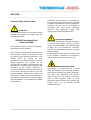
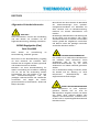
General Safety Instructions
ATTENTION!
This information needs to be considered during
handling and operation of products with the
following description:
ISOPAD Controllers (ICon)
Series Icon-4848
These will be referred as “product” through-out
this manual for ease of context.
Please read the manual carefully ahead of use of
these products. Follow the declaration on the
type plate and the warning instructions at the
product. Keep this manual for later
appropriation! This manual needs to be held in
charge apparently. The products can be
operated only according to occupational health
and safety law, regional safety regulations and
instructions of the Accident Prevention &
Insurance Association. Please take these advices
as part of the operating instructions of your QASystem Handbook. Handle these advices also
like a manual. Never remove warning labels on
the product! This product has been designed
and manufactured to the standards EN 14597
and EN 61010-1.
Installation, initial operation and maintenance
have to be executed according to the standards
EN 14597 and EN 61010-1 or other appropriate
standards. The unit has to be operated in
accordance with these norms, standards,
directives and regulations! Other local
requirements must be followed as well!
ELECTRICAL EQUIPMENT!
These products represent electrical equipment!
To prevent from danger caused by electric
energy, an earth leakage current breaker (ELCB
or RCD) has to be installed for protection
purpose. This ELCB should represent a tripping
current of 30mA.
To guard against electric shock, the devices have
to be installed, maintained and serviced by
authorized and trained staff and users only.
IINFLAMMATION AND EXPLOSION RISK!
The product is not explosion-proof. It should
never be integrated into tempering processes
where liquids handled may support explosions.
This covers also applications where gas/airmixtures may occur. The product must not be
used to heat explosive media or those
developing explosive gases when heated. The
product must only be installed outside
hazardous locations
4|P age-Seite
__________________________________________________________________________________
General Product Information
ISOPAD controllers Icon-4848 are compact
controllers for temperature controlling. They are
designed for panel mounting. The controllers
are programmable. Process value and set value
are shown on separate displays. Users can
choose between manual settings of the PID
values or an integrated auto-tuning function.
Different sensors, such as Pt100 and
thermocouples can be plugged to the controller.
The standard controller is equipped with an
output for Solid State Relays and has one normal
alarm-relay.
Note:
For the type specifications please refer to
technical data section, the product label or type
plate. In the case of installation difficulties or
special requirements it is recommended to
discuss and agree suitable installation
procedures. In case of doubt or if necessary
please contact us.
(see last page for contact information)
Additional Safety Instruction
(product related)
Attention!
For proper use and to prevent electrical shock,
injury of persons/animals and fire, international,
national and regional requirements, laws,
standards and directives need to be taken into
consideration.
The basic requirements during installation and
maintenance are to be followed necessarily:
- Do not use the equipment for any other
purpose than intended! (see section
“General Product Information”)
- Check the product data (product
identification against design and product
description)
- Check
IP-rating
(indoor/outdoor
implementation)
- Check Chemical resistance (corrosive
atmosphere)
- Check Ambient temperature area (allowed
values for equipment in ambient used)
- Before opening the housing disconnect from
energy supply!
- For suitable cable entry/outlet check gland
size. (see section “Technical Data”)
- Allow maintenance and service by authorized
and trained staff and users only.
- In case of failure or miss-operation
disconnect the system immediately from
power supply.
- The device should never be operated
without a residual current circuit breaker
device. (RCD or ELCB)
- Earth protection of any connected system
relies on the earth provided through the
supply line. Therefore never connect the
product without ground wire!
- All installations, connections and test have to
be carried out according to ISOPAD assembly
and mounting instructions.
5|Page-Seite
__________________________________________________________________________________
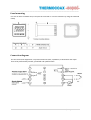
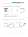
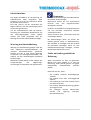
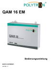
Panel mounting
Cut out an outlet of 45x45 +0.6/-0 and put the controller in. Fix the controller by using the attached
clamp
Connection diagram
The unit is electrical equipment. To prevent electrical shock, installation, maintenance and repair
have to be performed by trained, specialized and qualified staff!
6|Page-Seite
__________________________________________________________________________________
Installation
Before starting the installation, all technical
data
regarding
product
specification,
installation and use have to be checked
against design documentation. – see also
“Technical Data” and “Mounting”.
Pay attention to the following steps and to the
ISOPAD assembly and mounting instructions:
- Prior to connection of the thermostat,
please ensure that the mains voltage
matches that on the data label or in the
specifications, respectively.
- Check technical data sheet of connected
equipment
- Check necessary cross-section of cables
(in/out)
depending
on
required
performance. Compare with maximum
cross-sections shown in wiring diagrams on
the following pages
- The Controller unit should not get in
contact with corrosive components
- Metallic components coming in contact
with the controller unit have to be
incorporated into the protection measures
of Protection Class I (protective earth).
- For details please refer to relevant
standards and directives in your country.
- Follow the remarks as listed under the
topics “General Safety Instructions” and
“Additional Safety Instructions”!
- The temperature controller has to be rated
in such a manner that an exceeding of the
maximum admissible temperature is also
excluded for the feeding material or object,
respectively.
- It is absolutely necessary to use a residual
current circuit breaker in addition!
Controller and Sensor set-up:
The functionality of the controller unit relies on
the position and classification of the used
temperature sensor and the application
conditions. It is important to determine the
correct temperature sensor position to
accommodate
accurate
readings
and
adjustments. If not installed correctly the setpoint deviations may be larger than expected
during operation and temperature adjustments
may be difficult. Ensure that you are aware what
temperatures are critical in your application. If
you need any assistance please contact us.
Note:
The controller has no built-in main switch for
power “ON/OFF”.
7|Page-Seite
__________________________________________________________________________________
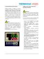
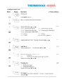
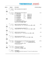
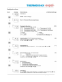
Programming the controller
Description
Before initial operation and setting the
installation alive, the equipment has to be
completely built-in requested integrity in the
ambient used.
Operating of the device is arranged in 2 levels.
The requested parameter can be called by the
MODE-button. For selection within a parameter
or entering data takes place with buttons
and .
The display scan takes place dynamically, i.e.
the regulating speed increases with the
operating time of the keys (1 ~ 10 s = 1 digit /
100 ms, 10 ~ 20s = 10 digit / 100 ms, > 20 s =
100 digit / 100 ms).
Start-up note:
Before the device can be used, it must be
configured first for the intended use.
Programming
Notes to representation:
Parameter appears only with appropriate
Configuration
Parameter appears only with appropriate
Equipment
After switching on the supply voltage, the
device initializes itself. The display shows the
code of the input configuration.
After the initializing procedure the device is
operating in the Working level.
Set value and process value are displayed. It is
possible to change Set point, Alarm points and
the manipulated value for process output 1
and 2 if manual mode is active.
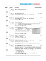
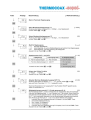
Please note:
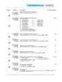
During configuration all available parameters
are indicated, which were not excluded by
other parameter settings. Factory settings
are shown in [ ].
Activating the MODE-button for more than
2 seconds, the program is jumping into the
Configuration level.
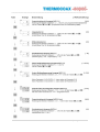
Now all the parameters defining the function
of the controller can be programmed. All data
are stored zero-voltage safe.
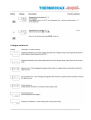
After finishing the configuration or when
longer than 120 seconds no button was
pushed, the program jumps back to the
working level. Leaving the configuration level
is possible at any time by pushing the MODEbutton for 2 seconds.
8|Page-Seite
__________________________________________________________________________________
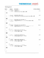
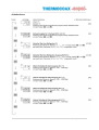
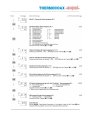
Working Level
9|Page-Seite
__________________________________________________________________________________
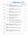
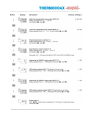
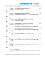
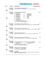
Configuration Level
10 | P a g e - S e i t e
__________________________________________________________________________________
11 | P a g e - S e i t e
__________________________________________________________________________________
12 | P a g e - S e i t e
__________________________________________________________________________________
13 | P a g e - S e i t e
__________________________________________________________________________________
14 | P a g e - S e i t e
__________________________________________________________________________________
15 | P a g e - S e i t e
__________________________________________________________________________________
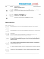
Configuration level
16 | P a g e - S e i t e
__________________________________________________________________________________
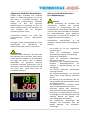
Initial Operation
SSR-drive output. Please refer to technical data
for further technical information.
Make sure the mains voltage has the same value
as described on the unit’s product-label.
A LED on the front of the controller ("Out 1”)
indicates if the output is on (switch closed).
Maintenance and Safety
Maintenance and Safety is performed according
to the standards listed under "General Safety
Instructions"
and
“Additional
Safety
Instructions”, the regulations of the employer's
liability insurance associations applicable to the
respective way of use, as well as other relevant
rules applying to the application. At least once
per year the function of the temperature
controlling and temperature limiting safety
device has to be checked and the surface and
supply line should be inspected for visible
damage.
Repair:
If Repairs, then only to be carried out
(in factory) by original manufacturer.
Rearrangement or variances of design can
influence the performance. Those actions
need to be carried out by the manufacturer!
Only original spare parts have to be
implemented and equipment authorized by
the manufacturer!
When returned, please always confirm
decontamination status in written form and
support this information directly with the
returned product.
If a decontamination form is required, then
please get in contact with us, where we will
support you.
Please refer to “Technical Data” within this
operation manual for full technical details
Malfunction and Excessive Strain
If it has been assumed that safe operation is no
longer possible, the installation must be
permanently shut down and secured against
being inadvertently put back into operation.
This is the case, if…
… the product shows visible signs of damages
… the product is not operating according to
specification
… the product is not operating at all (no visible
indication of reason)
… the product has been exposed to excessive
strain
… the admissible product limits are exceeded
(e.g. storage, transportation, operating
temperature)
Environmental information for
industrial customers within the
European Union
To demand of the European Directive
2002/95/EC and of the national Product Safety
Act, equipment that is equipped with this
symbol directly provided on or with the
product and / or its packaging must not be
disposed of together with unsorted municipal
waste. The symbol indicates that the product
should be disposed of separately to regular
industrial /domestic waste.
It is your responsibility to use this product and
other electrical and electronic products only
on the legally prescribed methods of disposal
or the competent and of the government or
local authorities defined collection points for
disposal. Correct disposal and recycling will
help prevent potential negative consequences
for the environment and human health.
If you need further information about disposal
of your old equipment, please contact the
local authorities, waste disposal service or the
dealer from whom you purchased the
product.
17 | P a g e - S e i t e
__________________________________________________________________________________
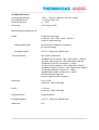
Technical Data
Supply voltage:
Power consumption:
Operating temperature:
Approvals:
100 V ... 240 V AC - 50/60 Hz,
or
24 V AC/DC
< 10 VA at 240 V AC
0 ... 50°C
Please refer to specification plate
Sensor Type:
Pt100:
- Line resistance:
- Accuracy:
Thermocouple:
Current:
Voltage:
Sensor correction:
Accuracy:
Sampling rate:
Pt100 DIN and JPt100 from -199 ...500 /
-199.9 ...500.0°C
2-or 3-wire connection
up to 10 Ohm
no adjustment necessary
(3-wire connection)
± 0.3 % + 1 Digit of measuring range
without /with decimals
Typ K (NiCr-Ni) from -200 …1372 / -199.9 … 990.0°C
Typ J (Fe-CuNi) from -200 …850 / -199.9 … 850.0°C
Typ R (PtRh-Pt 87/13) from 0 …1700°C
Typ T (Cu-CuNi) from -200 …400 / -199.9 … 390.0°C
Typ N (NiCrSi-NiSi) from -200 …1300 / -199.9 … 990.0°C
Typ S (PtRh-Pt90/10) from 0 …1700°C
Typ B (Pt30Rh /Pt6Rh) from 0 …1800°C
monitoring break of sensor,built-in cold junction
4… 20 mA from -1999 … 9999 Digit
0/1… 5 V DC from -1999 … 9999 Digit
programmable
± 0.3 % + 1 Digit of measuring range
0.5 s
18 | P a g e - S e i t e
__________________________________________________________________________________
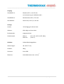
Output
ICon4848-P-A:
ICon4848-R-A:
Bi-stable, 0/12 V, max. 20 mA, for SSR drive
Relay contact, 250 V / 3 A max.
All models:
Alarm relay, 250 V / 2.4 A max.
Display
Process value:
LED 4-Digit green 10 mm
Set value:
LED 4-Digit red 8 mm
Decimals:
programmable
Status indicators:
LED red (AL1, AL2, OUT1, OUT2, RDY),
LED green (COM, DI)
Case:
Panel mounting
Dimensions:
48 x 48 x 77 mm, weight 180 g
Protection:
Front IP66
Terminals:
Screw terminals max. 2.5 mm2
19 | P a g e - S e i t e
__________________________________________________________________________________
DEUTSCH
__________________________________________________________________________________
Allgemeine Sicherheitshinweise
ACHTUNG!
Diese Informationen sind bei der Handhabung
und dem Betrieb von Produkten mit der
folgenden Bezeichnung unbedingt zu beachten:
ISOPAD Regelgeräte (ICon)
Serie ICon4848
Diese werden zur Vereinfachung
Zusammenhang „Produkte“ genannt.
Bitte nehmen Sie diese Hinweise als Bestandteil
der Arbeitsanweisungen Ihres Qualitätsmanagement-Handbuchs auf. Behandeln Sie
diese Hinweise auch als Betriebsanweisung.
Entfernen Sie niemals Warnhinweise vom
Produkt!
Bei Montage, Inbetriebnahme und Wartung sind
die EN 14597 und EN 61010-1 oder andere
zutreffende Normen zu beachten. Die Produkte
müssen gemäß den aufgeführten Vorschriften
und Normen sowie den jeweiligen nationalen
Vorschriften betrieben werden!
im
Bitte lesen Sie die Betriebsanleitung sorgfältig
vor dem Gebrauch des Produktes. Bitte
beachten Sie die Angaben auf dem Typenschild
und die Warnhinweise am Produkt.
Bewahren Sie diese Betriebsanleitung für
spätere Verwendung des Produktes unbedingt
auf! Sie soll bei der Anwendung sichtbar
bereitgehalten sein. Das Produkt ist nur nach
dem
Arbeitssicherheitsgesetz
und
den
jeweiligen Landesvorschriften und zutreffenden
Vorschriften und Regeln der Berufsgenossenschaften (in Deutschland: z. B. BGV und
BGR) zu betreiben.
ELEKTRISCHES BETRIEBSMITTEL!
Das Produkt ist ein elektrisches Betriebsmittel!
Um Gefahren durch elektrischen Strom
vorzubeugen, darf es nur über einen
Fehlerstrom-Schutzschalter (FI) mit einem
Auslösestrom von 30mA in Betrieb genommen
werden.
Um vor elektrischem Schlag zu schützen, dürfen
der Betrieb und die Wartung nur durch
Fachpersonal
(Elektrofachkraft)
oder
eingewiesenes Personal erfolgen.
BRAND- UND EXPLOSIONSGEFAHR!
Diese Komponente ist nicht explosionsgeschützt. Deshalb darf sie nicht für
Wärmeprozesse eingesetzt werden, bei denen
eine Gefahr durch explosive Medien oder
explosive Gas-Luft-Gemische entstehen kann.
Sie darf nicht im explosionsgefährdeten Bereich
betrieben werden.
20 | P a g e - S e i t e
__________________________________________________________________________________
Allgemeine Produkt Informationen
ISOPAD Regler ICon4848 sind kompakte
Regler zur Temperaturregelung. Sie sind für
den Einbau in Fronttafeln konzipiert. Die
Regler sind programmierbar, außerdem
verfügen
sie
über
zwei
getrennte
Digitalanzeigen zur Darstellung von Soll- und
Istwert. Bediener können die PID Werte manuell eingeben oder die integrierte
Autotuning-Funktion nutzen.
Verschiedene Sensoren wie Pt100 oder
Thermoelemente können angeschlossen
werden.
Der Regler verfügt standardmäßig über einen
Regelausgang
zur
Ansteuerung
von
Halbleiterrelais (SSR) sowie ein Alarmrelais.
Wichtig:
Individuelle Daten entnehmen Sie daher bitte
dem Abschnitt technische Daten, dem ProduktTypenschild oder -aufkleber. Es wird empfohlen
bei Fragen zum Einbau oder in speziellen
Bedarfsfällen die geeigneten Montagevorschriften individuell abzusprechen und zu
vereinbaren. Falls notwendig kontaktieren Sie
uns hierzu bitte. (siehe letzte Seite für
Kontaktinformationen)
Weitere Sicherheitshinweise
(Produktbezogen)
Achtung!
Bei der Verwendung des Produktes sind
internationale, nationale oder regionale
Vorschriften zu berücksichtigen, um die
zweckbestimmte Verwendung zu gewährleisten
und Sach- oder Personenschäden zu vermeiden.
Die Schutzmaßnahmen gegen gefährliche
Körperströme sind gemäß den Angaben der
aufgeführten Normen auszuführen.
Grundsätzliche
Anforderungen
an
die
Installation und den Betrieb sind unbedingt zu
beachten:
- Das Produkt nur für den vorgesehenen
Zweck einsetzen!
- Prüfen
der
Produktdaten
(Produktbeschreibung, Auslegung, Kennzeichnung)
- Prüfen der IP-Schutzklasse
- Prüfen der chemischen Beständigkeit
(korrosive Umgebung)
- Überprüfung des Umgebungstemperaturbereiches
(Einsatztemperaturen
der
Produkte in Übereinstimmung mit der
Anwendung)
- Bei Öffnung elektrischer Betriebsmittel
Trennung vom Netz!
- Bei Kabelverschraubungen auf passende
Größe achten (siehe Abschnitt „technische
Daten“)
- Die Wartung und Instandhaltung darf nur
von geschultem und authorisiertem Personal
durchgeführt werden.
- Bei Fehlfunktion eines Produktes dieses
sofort vom Betriebsstromkreis trennen!
- Heizsystem niemals ohne Absicherung,
Fehlersromschutzschalter (FI) betreiben!
- Die Erdung von angeschlossenen Systemen
ist abhängig von dem Erdungsanschluss der
Zuleitung. Niemals das Produkt ohne
Schutzerdungsleiter anschliessen!
- Alle Installationen, Verbindungen und
Prüfungen sind auszuführen nach den
ISOPAD Montage- und Installationsanweisungen.
21 | P a g e - S e i t e
__________________________________________________________________________________
Fronttafeleinbau
Fertigen Sie einen Ausschnitt von 45x45 (+0,6/-0) mm und stecken Sie den Regler ein.
Befestigen Sie den Regler mit der beigefügten Klammer.
Anschlussplan
ICon4848 Regler sind elektrische Betriebsmittel! Um Gefahren durch elektrischen Strom vorzubeugen
dürfen Arbeiten an Reglern nur von fachkundigem und geschultem Personal durchgeführt werden.
22 | P a g e - S e i t e
__________________________________________________________________________________
Installation
Achten Sie auf die folgenden Schritte und auf
die ISOPAD Installationsanweisungen:
- Vor
dem
Netzanschluss
ist
die
Übereinstimmung der Netzspannung mit
der des Thermostaten Typenschild zu
überprüfen.
- Überprüfen Sie das Datenblatt der
angeschlossene Bauteile.
- Bitte prüfen Sie die erforderlichen
Leitungsquerschnitte und vergleichen Sie
diese mit den Angaben im Anhang bzw.
den Angaben in den nachfolgenden
Schaltplänen.
- Die Reglereinheiten dürfen nicht mit
aggressiven Medien in Kontakt kommen.
- Metallische Bauteile, die mit dem Regler in
Berührung kommen, müssen in die
Schutzmaßnahmen der Schutzklasse I
(Schutzerdung) einbezogen werden.
- Für weitere Details bitte einschlägige
Normen und Richtlinien Ihres Landes
einsehen!
- Beim Anschluss sind die Forderungen der
unter Punkt "Allgemeine Sicherheitshinweise" und „Weitere Sicherheitshinweise“ aufgeführten Normen zu
beachten.
- Die Auswahl des Temperaturreglers hat so
zu erfolgen, dass eine Überschreitung der
höchstzulässigen Temperaturen auch
durch das zu beheizende Material oder der
Anlagenteile vermieden wird.
- Zusätzlich ist eine Überstrom-Sicherung
(FI-Schutz) vorzusehen
Regler- und Fühleraufbau:
Die Funktionalität der Reglereinheit ist abhängig
von der Position und Klassifizierung des
verwendeten Temperaturfühlers und den
Anwendungsbedingungen.
Es ist wichtig die richtige Fühlerposition zu
bestimmen um genaue Temperaturmessungen
zu erahlten und Anpassungen vornehmen zu
können.
Falls nicht richtig installiert können die
Abweichungen während des Betriebes
gegenüber des eingestellten Sollwertes
grösser sein als angenommen und weitere
Einstellungen schwierig werden. Stellen Sie
sicher das Sie wissen welche Temperaturen in
Ihrer Anwendung kritisch sind. Falls Sie
Unterstützung benötigen kontaktieren Sie uns
bitte.
Hinweis:
Das Regelgerät hat keinen
Hauptschalter für „AN/AUS“
eingebauten
23 | P a g e - S e i t e
__________________________________________________________________________________
Programmierung des Reglers
Beschreibung
Vor Montage und Anschluß unbedingt die
zugehörigen technischen Daten gegen die
Auslegungsdaten überprüfen.
Die Bedienung des Reglers erfolgt in 2 Ebenen.
Der gewünschte Parameter wird mit der
MODE-Taste aufgerufen. Die Auswahl
innerhalb eines Parameters bzw. die
Einstellung eines Wertes erfolgt mit den
Tasten
und
.
Die Einstellung erfolgt dynamisch, d.h. die
Stellgeschwindigkeit erhöht sich mit der
Betätigungszeit der Tasten (1 ~ 10 s = 1 digit /
100 ms, 10 ~ 20s = 10 digit / 100 ms, > 20 s =
100 digit / 100 ms).
Nach dem Einschalten der Hilfsspannung
initialisiert sich das Gerät. Im Display erscheint
der Code für die Eingangskonfiguration.
Nach Ablauf der Initialisierung befindet sich
das Gerät in der Arbeitsebene. Im Display
wird der aktuelle Messwert sowie der Sollwert
angezeigt. Hier können der Sollwert, die
Schaltpunkte der Alarmkontakte sowie der
Stellgrad für Ausgang 1 und 2 bei Handbetrieb
geändert werden.
Hinweis zur Inbetriebnahme
Das Gerät ist werksseitig mit einer Standardeinstellung vorbelegt. Es muss daher noch an
den speziellen Einsatzfall angepasst werden.
Programmierung
Hinweis zur Darstellung
Parameter erscheint nur bei entsprechender
Konfiguration
Parameter erscheint nur bei entsprechender
Ausführung
Hinweis:
Es werden beim Konfigurieren immer nur die
Parameter angezeigt, die nicht durch andere
Parametereinstellungen ausgeschlossen wurden
und innerhalb der Geräteausführung verfügbar
sind. Werksseitig vorbelegte Einstellungen sind
in [ ] dargestellt.
Durch 2 Sekunden langes Betätigen der
MODE-Taste wird die Konfigurationsebene
aufgerufen. Hier werden nun alle Parameter
programmiert, welche die Eigenschaften des
Regler bestimmen. Alle Änderungen sind
sofort nullspannungssicher gespeichert.
Wenn länger als 120 Sekunden keine Taste
betätigt wird, erfolgt automatisch ein
Rücksprung in die Arbeitsebene. Die
Konfigurationsebene kann zu jedem Zeitpunkt
durch 2 Sekunden langes Betätigen der
MODE-Taste verlassen werden.
24 | P a g e - S e i t e
__________________________________________________________________________________
Arbeitsebene
25 | P a g e - S e i t e
__________________________________________________________________________________
Konfigurierebene
26 | P a g e - S e i t e
__________________________________________________________________________________
27 | P a g e - S e i t e
__________________________________________________________________________________
28 | P a g e - S e i t e
__________________________________________________________________________________
29 | P a g e - S e i t e
__________________________________________________________________________________
30 | P a g e - S e i t e
__________________________________________________________________________________
31 | P a g e - S e i t e
__________________________________________________________________________________
Konfigurationsebene
32 | P a g e - S e i t e
__________________________________________________________________________________
Inbetriebnahme
Der Regler ICon4848 ist zur Ansteuerung von
Halbleiterrelais (SSR) vorgesehen. Bitte
beziehen Sie sich auf die technischen Daten
für weitere Informationen.
Eine LED („Out1“) auf der Vorderseite des
Reglers indiziert, dass der Schaltausgang aktiv
ist (Schalter geschlossen).
Vor der Inbetriebnahme sollte die Übereinstimmung der verwendeten Komponenten mit
den Zeichnungsvorgaben erneut geprüft
werden. Dies sollte unmittelbar nach der
Montage und vor der Inbetriebnahme erfolgen.
Wartung und Instandhaltung
Wartung und Instandhaltung erfolgen nach den
unter "Allgemeine Sicherheitshinweise" und
„Weitere
Sicherheitshinweise“
genannten
Normen und den je nach Einsatz geltenden
Vorschriften der Berufsgenossenschaften und
anderen, auf den Anwendungsfall zutreffende
Bestimmungen.
Mindestens einmal jährlich ist die Funktion der
Temperaturregelund
Begrenzungseinrichtungen zu überprüfen und aufzuzeichnen.
Reparatur:
Umbau oder Veränderungen der Einheit können
die Funktion beeinträchtigen.
Reparaturen dürfen nur von autorisiertem
Personal oder vom Original-Hersteller
durchgeführt werden.
Es dürfen ausschließlich nur Originalersatzteile
und vom Hersteller autorisiertes Zubehör
verwendet werden!
Sehen sie hierzu unter „Technische Daten die
notwendigen Details.
Bei Rücksendungen bitten wir darum das
Produkt generell vorher zu dekontaminieren,
dies schriftlich zu bestätigen und dem Produkt
als Information beizulegen. Wenn Sie eine
Dekontaminationsvorlage benötigen, nehmen
Sie dazu bitte Kontakt mit uns auf.
Fehler und außergewöhnliche
Belastung
Wenn anzunehmen ist, dass ein gefahrloser
Betrieb nicht mehr möglich ist, so muss die
Einrichtung außer Betrieb gesetzt und gegen
unabsichtliche
Inbetriebnahme
gesichert
werden.
Dieser Fall tritt ein, wenn…
… das Produkt sichtbare Beschädigungen
aufweist
… das Produkt nicht mehr ordnungsgemäß
arbeitet
… das Produkt gar nicht mehr arbeitet (ohne
ersichtlichen Grund)
… das Produkt Überbeanspruchung jeglicher
Art ausgesetzt war
... die zulässigen Grenzen überschritten
wurden
(z.B.
Lagerung,
Transport,
Betriebstemperatur)
33 | P a g e - S e i t e
__________________________________________________________________________________
Umweltinformation für
industrielle Kunden innerhalb
der Europäischen Union
Die Europäische Richtlinie 2002/95/EC und das
deutsche Produktsicherheitsgesetz verlangen,
dass technische Ausrüstung, die direkt am oder
mit dem Produkt und/oder an der Verpackung
mit diesem Symbol versehen ist, nicht
zusammen mit unsortiertem Gemeindeabfall
entsorgt werden darf.
Das Symbol weist darauf hin, dass das Produkt
von
regulärem
Gewerbe-/Haushaltsmüll
getrennt entsorgt werden sollte.
Es liegt in Ihrer Verantwortung, dieses Produkt
und andere elektrische und elektronische
Produkte nur über die gesetzlich vorgeschriebenen Entsorgungswege bzw. die dafür
zuständigen und von der Regierung oder
örtlichen
Behörden
dazu
bestimmten
Sammelstellen zu entsorgen.
Ordnungsgemäßes Entsorgen und Recyceln
trägt dazu bei, potentielle negative Folgen für
Umwelt und die menschliche Gesundheit zu
vermeiden.
Wenn Sie weitere Informationen zur Entsorgung
Ihrer Altgeräte benötigen, wenden Sie sich bitte
an die örtlichen Behörden oder städtischen
Entsorgungsdienste oder an den Händler, bei
dem Sie das Produkt erworben haben.
34 | P a g e - S e i t e
__________________________________________________________________________________
Technische Daten
Versorgungsspannung:
Leistungsaufnahme:
Arbeitstemperatur:
Zulassung:
100 V ... 240 V AC 50/60 Hz, oder 24 V AC/DC
< 10 VA bei 240 V AC
0 ... 50°C
Siehe Typenschild
Messeingang konfigurierbar für:
Pt100:
Pt100 DIN und JPt100
im Bereich -199 ...500 / -199,9 ...500,0°C
2-oder 3-Leiterschaltung
-Leitungswiderstand:
bis 10 Ohm kein Abgleich erforderlich
(3-Leiterschaltung)
-Grundgenauigkeit:
± 0,3 % + 1 Digit vom Messbereich
Thermoelemente:
ohne /mit Dezimalstelle
Typ K (NiCr-Ni) im Bereich -200 …1372/-199,9 … 990,0°C
Typ J (Fe-CuNi) im Bereich -200…850/-199,9…850,0°C
Typ R (PtRh-Pt 87/13) im Bereich 0 …1700°C
Typ T (Cu-CuNi) im Bereich -200…400/-199,9…390,0°C
Typ N (NiCrSi-NiSi) im Bereich -200…1300/-199,9…990,0°C
Typ S (PtRh-Pt90/10) im Bereich 0 …1700°C
Typ B (Pt30Rh /Pt6Rh) im Bereich 0 …1800°C
Fühlerbrucherkennung und
interne Vergleichsstelle eingebaut
Spannung:
0/1…5 V DC
im Bereich -1999…9999 Digit
Strom:
4…20 m A
im Bereich -1999…9999 Digit
Fühlerkorrektur:
programmierbar
Grundgenauigkeit:
± 0,3 % + 1 Digit vom Messbereich
Abtastrate:
0,5 s
35 | P a g e - S e i t e
__________________________________________________________________________________
Ausgang
ICon4848-P-A:
Bistabil, 0/12 V, max. 20 mA,
zur Ansteuerung von Halbleiterrelais
ICon4848-R-A:
Relaiskontakt, 250 V / 3 A max.
Alle Modelle:
Alarmrelais, 250 V / 2,4 A max.
Anzeige
Istwert:
LED 4-Digit grün 10 mm hoch
Sollwert:
LED 4-Digit rot 8 mm hoch
Dezimalpunkt:
programmierbar
Schaltzustand:
LED rot
LED Grün
(AL1, AL2, OUT1, OUT2, RDY),
(COM, DI)
Gehäuse:
Schalttafeleinbaugehäuse
Abmessungen:
48 x 48 x 77 mm,
Gewicht:
180 g
Schutzart:
Front IP66
Klemmen:
Schraubklemmen max. 2,5 mm
2
36 | P a g e - S e i t e
__________________________________________________________________________________
Notes / Notizen
37 | P a g e - S e i t e
__________________________________________________________________________________
Notes / Notizen
38 | P a g e - S e i t e
H
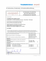
EC Declaration of Conformity / EG Konformitatserklarung
EC Declaration of Conformity
EG Konformltatserklarung
CE Declaration de Conformite
We / Wir / Nous,
THERMOCOAX ISOPAD GmbH
EnglerstraBe 11, 0-69126 Heidelberg / Germany - Deutschland - Allemagne
hereby declare in our sole responsibility, that the products...
erklaren in alleiniger Verantwortung, dassdie Produkte .
declarons de notre seule responsabillte, que les produits .
Digital Temperature Controllers for mounting of Series
Digitale Einbau-Temperaturregler der Serie
Regulateurs de temperature digital d'insert de Series
ICon4848
...which is the subject of this declaration, is in conformity with the following standard(s)or normative documents
...auf dassich diese Erklarung bezieht, mit der/den folgenden Norm(en) oder normativen Dokumenten uberelnstlmmt
...auquel cette declaration se rapporte, est coriforme aux norme(s) ou aux documents normatifs suivants
Terms of the Directive(s) and Approval Data...
Title and/or No. and date
of issue of the standard /
Bestimmungen der Richtlinie und Zulassungsdaten...
Titel und/oder Nr. sowie
Ausgabedatum der Norm /
Prescription de la directive et donnees de reference 'approbation ...
titre et/ou No. ainsi que date
d'ernlssion des normes
2006/95/EC:
"Electrical equipment designed for use within certain voltage limits"
2006/95/EG:
"Elektrische Betriebsmittel zur Verwendung innerhalb bestimmter
Spannungsgrenzen"
EN 14597 :2005
EN 61010-1 :2011
+}
EN 61000-6-2
+}
EN 61000-6-4
+}
2006/95/CE:
"materiel electrique destine
2004/108/EC:
2004/108/EG:
2004/108/CE:
Heidelberg,
a etre employe dans certaines Iimites de tension"
Electromagnetic compatibility
Elektromagnetische Vertraglichkelt
Compatiblllte electromagnetlque
os"June 2012
C', : c(~:.9J
+) Harmonized Standards
I
Ge~ntan Schild
pres\4ent / GeschaftsfUhrer / Directeur General
I
I Pa g e - Se it e
Unsere Produkte erfüllen die
Anforderungen der zutreffenden
europäischen Richtlinien.
© 2012 THERMOCOAX ISOPAD
Our products satisfy the
requirements of the relevant
European Directives.
1235-OMH58733 R12-0
__________________________________________________________________________________
Nos produits répondent
aux exigences des directives
européennes appropriées
.
____________________________________________________________________
Thermocoax Isopad GmbH
Englerstrasse 11
D-69126 Heidelberg
Germany
Tel: +49 (0) 6221 3043 0
Fax: +49 (0) 6221 3043 956
Mail to: [email protected]
Web: www.thermocoax.com
ISOPAD is a trademark of THERMOCOAX ISOPAD GmbH or its affiliates.
ISOPAD ist ein eingetragenes Warenzeichen von THERMOCOAX ISOPAD GmbH
oder ihren Tochtergesellschaften.
ISOPAD est une marque déposée de THERMOCOAX ISOPAD GmbH ou ses affiliées.
www.isopad.com
40 | P a g e - S e i t e