1
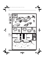
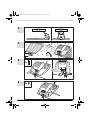
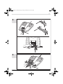
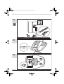
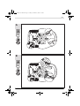
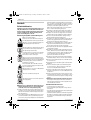
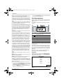
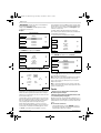
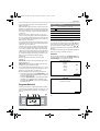
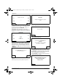
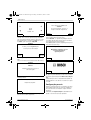
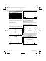
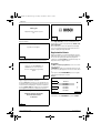
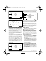
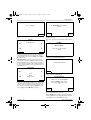
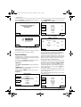
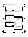
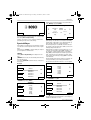
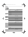
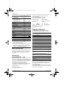
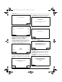
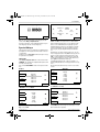
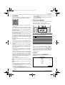
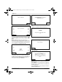
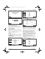
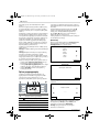
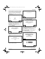
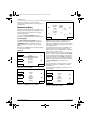
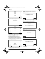
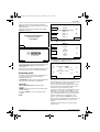
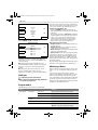
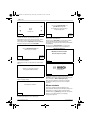
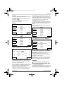
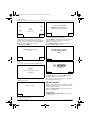
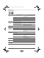
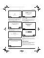
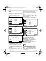
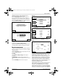
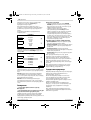
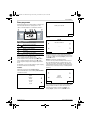
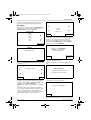
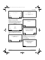
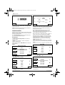
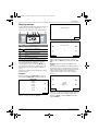
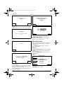
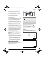
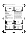
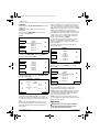
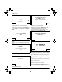
OBJ_BUCH-1573-003.book Page 27 Friday, November 23, 2012 9:10 AM English | 27 connect the wire to the right hand (red) terminal. (see figures 4 – 5) Fix the docking station with 4 supplied fixing pins to the ground. (see figure 6) Lay out the perimeter wire anti-clockwise and flush to the ground. Observe the minimum distances from lawn edges, steps, walls, ponds, etc. Use the spacing guide. (see figure 7) Trees, ponds, flower beds, etc. on the lawn must be delimited in clockwise direction. The lines to and from these zones may not cross but the wire should be touching. (see figure 7) Fix the wire with the first peg next to the docking station, tension and fix with pegs at a distance of approx. 50 cm. (see figure 7) Continue the loop and bring the wire to the back of the docking station and inline with the other end of the wire. Fix the second end of the wire also with the peg. Perimeter wire and peg should be installed inline. Shorten the wire, cut off insulation carefully and connect the wire to the left hand (black) terminal. (see figure 8) Clip on the protective cover of the docking station. (see figure 9) Note: The wire can be extended up to the maximum allowed length of 450 m. Note: If verticutting or raking is intended avoid the perimeter wire. Install the power supply in a cool, dry environment. Connect it with the docking station and an indoor mains socket. (see figure 10) Check the indicator on the docking station (see figure 11): – Indicator lights up continuously green, if the output voltage of the power supply is available and the perimeter wire is not interrupted. – Indicator flashes green, if the perimeter wire is broken, long or short. – Indicator does not light up when the output voltage of the power supply is not available. Symbol Meaning Display with dialog screens Time Multifunctional buttons, right The buttons are multifunctional. The meaning depends on the individual menu function and is explained on the screen. The buttons next to the arrow symbols or allow to navigate up or down through the menu options. The buttons next to the arrow symbols or allow to go right or left through the menu options. The display will change to the next screen as soon as any option is selected and confirmed. Installation First press the button next to “Language choice”. The “Set Language” screen appears and shows the following. Set Language English Deutsch Dansk Svenska Norsk Suomi Save Select one of the “Language” options and confirm with “Save”. PIN Code Please set up PIN Code Initial Programming Plug the isolator key into the machine and put it into the docking station for charging. (see figures 12 – 14) The welcome screen appears and shows following symbols: Proceed Select “Proceed” to enter your personal PIN Code. PIN Code Enter new PIN: Robotic Lawnmower __ _ _ Back Symbol Meaning Multifunctional buttons, left Battery capacity Title of Menu/Submenu Bosch Power Tools Enter Select the input position with the left/right cursors, adjust the digits with the up/down cursors and confirm with “Enter” or select “Back” to return to the first “PIN Code” screen. F 016 L70 825 | (23.11.12)