1
Page 7
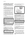
The hot gas circulating into the serpentine of the
evaporator warms up the copper molds causing
the harvest of the ice cubes. The ice cubes,
released from the cups, drop by gravity onto a
slanted cube chute, then through a curtained
opening they fall into the storage bin.
On 1706, 2008, 2608, 2615, 3515 and 4422 when
the temperature of the evaporator thermostat
bulb reaches the value of +3÷4°C their electrical
contacts move back to the previous position
activating a new freezing cycle and deenergizing
both the hot gas and the water inlet valves (closed).
On 5522, 7040, 8040 and 9050 as soon as the
electronic timer completes the defrost cycle, it
activates a new freezing cycle deenergizing both
the hot gas and the water inlet valves (closed).
NOTE. On models 1706, 2008, 2608, 2615,
3515 and 4422 the length of the defrost/
harvest cycle (not adjustable) changes according
to the ambient temperature (shorter for hi
ambient temperature and longer for low one).
COMPONENTS DESCRIPTION
A. WATER PUMP
The water pump operates continually throughout
the freezing cycle. The pump primes the water
from the sump to the spray system and through
the spray nozzles sprays it into the inverted cup
molds to be frozen into crystal clear ice cubes.
B.
WATER INLET SOLENOID VALVE 3/4 MALE FITTING
The water inlet solenoid valve is energized only
during the defrost cycle.
When energized it allows a metered amount of
incoming water to flow over the evaporator cavity
to assist the hot gas in defrosting the ice cubes.
The water running over the evaporator cavity
drops by gravity, through the dribbler holes of the
platen, into the sump reservoir.
On 1706, 2008, 2608, 2615, 3515, 4422 and
5522 water cooled versions the water inlet
solenoid valve has one inlet and two outlets with
two separate solenoids energized the first (ice
productioon) by the contacts 3-2 of the evaporator
thermostat and the second (water cooled
condenser) by a specific hi pressure control.
C. HOT GAS SOLENOID VALVE
The hot gas solenoid valve consists basically in
two parts: the valve body and the valve coil.
During the defrost cycle the hot gas valve coil is
activated so to attract the hot gas valve piston in
order to give way to the hot gas discharged from
compressor to flow directly into the evaporator
serpentine to defrost the formed ice cubes.
D. BIN THERMOSTAT
The bin thermostat control body is located in the
front of control box behind the front panel.
The thermostat sensing tube is located into a
bulb holder on the side wall of the ice storage bin
where it automatically shuts the icemaker OFF
when in contact with the ice and re-starts the
icemaker when the ice is removed. Factory
settings are 1°C (35°F) OUT and 4°C (39°F) IN.
E.
CUBE SIZE CONTROL (EVAPORATOR
THERMOSTAT)
1706 - 2008 - 2608 - 2615 - 3515 - 4422
The cube size control (evaporator thermostat)
body is located in the control box behind the front
panel; it’s basically a reverse acting temperature
control which closes the contacts 3-2 when its
temperature decreases and closes the opposite
contacts 3-4 when the temperature rises.
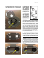
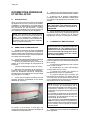
The thermostat sensing bulb is located into a
plastic tube (bulb holder) secured by two clips
directly to the evaporator serpentine.
This control determines the length of the freezing
cycle and correspondingly the size of the cubes.
A lower setting will produce a larger cube
(oversize) while a higher setting a smaller cuber
(shallow size).
When closed on contacts 3-2 it activates the
defrost or harvest cycle components.
The cube size control is set up in the factory
(knob in the black dot position) and doesn't
require any adjustment when the ambient
temperature remains between 20 and 30°C
(70 and 90°F).
5522 - 7040 - 8040 - 9050
The evaporator thermostat with its sensing bulb
intimately in contact with the regrigerant outlet
tube from the evaporator senses the evaporating
refrigerant temperature (which declines in the
course of the freezing cycle) and when this one
reaches the pre-set value, it switches its contacts
from 3-4 to 3-2 to activate the finishing cycle (2nd
phase) through an electronic timer.
F. FAN MOTOR (Air cooled version)
The fan motor on 1706, 2008, 2608, 2615, 3515,
4422 is electrically connected in parallel to the
water pump and it operates continuously only
during the freezing cycle keeping the proper
head pressure by circulating air through the
condenser fins.
On 5522, 7040, 8040 and 9050 the operation of
fan motor is controlled by a fan pressure control
adjusted at preset values.
G. COMPRESSOR
The hermetic compressor is the heart of the
refrigerant system and it is used to circulate and
retrieve the refrigerant throughout the entire
system. It compresses the low pressure
refrigerant vapor causing its temperature to rise
and become high pressure hot vapor (hot gas)
which is then released through the discharge
valve.
H. WATER SPRAY SYSTEM
Through its nozzles it sprays the water in each
individual cup to be frozen into ice.