1
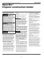
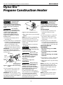
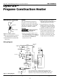
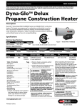
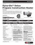
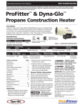
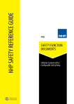
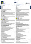
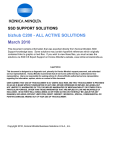
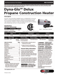
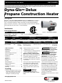
RMC-FA300DGD Operating Instructions & Parts Manual Dyna-GloTM Delux Propane Construction Heater Description Dyna-GloTM Delux Model RMC-FA300DGD heaters are 300,000 BTU/Hr construction heaters. This heater uses propane gas for combustion, and electricity to run the fan. It is primarily intended for temporary heating of well-ventilated buildings under construction, alteration or repair. This heater should be utilized in sheltered, well-ventilated areas, but never in occupied dwellings. Electrical Specifications Model Electrical Input Amperage 120 V, 60 Hz 0.65 RMC-FA300DGD C Figure 1 - Model RMC-FA300DGD US US C CSA 2.14b-2009, ANS Z83.7b-2009 Construction Heater General Specifications Model Output Rating BTU/Hr Fuel Maximum Fuel Consumption Ignition RMC-FA300DGD 300,000 13.9 Lbs/Hr Model Propane Vapor Only Hot Air Output Approx. (CFM) Motor RMC-FA300DGD 1800 Regulator Outlet Pressure Direct Spark, Interrupted 7-10 PSIG Minimum Supply Pressure to Regulator Maximum Supply Pressure to Regulator Size L x W x H (Inches) Weight (pounds) 0.085 HP 25 PSIG (For purposes Max Bottle Pressure 33.7 x 12.6 x 18.5 33.9 (Heater) 1,720 RPM of input adjustment) Table of Contents Page Description . . . . . . . . . . . . . . . . . . . . . . . 1 Specifications . . . . . . . . . . . . . . . . . . . . . 1 Unpacking . . . . . . . . . . . . . . . . . . . . . . . 1 General Safety Information . . . . . . . . 1-3 Theory of Operation . . . . . . . . . . . . . . . 3 Installation . . . . . . . . . . . . . . . . . . . . . . 3-4 Ventilation . . . . . . . . . . . . . . . . . . . . . . . 4 Operation . . . . . . . . . . . . . . . . . . . . . . . 4-5 Maintenance . . . . . . . . . . . . . . . . . . . . 5-6 Storage . . . . . . . . . . . . . . . . . . . . . . . . . . 6 Wiring Diagram . . . . . . . . . . . . . . . . . . . 6 Repair Parts Illustration and Parts List . . . . . . . . . . . . . . . . . . . . 7-8 Troubleshooting Chart . . . . . . . . . . . . . 9 Warranty . . . . . . . . . . . . . . . . . . . . . . . . 10 Unpacking 1.Unpack all materials used to protect the heater inside of carton. Retain plastic caps attached to exposed fittings for use during storage. 2.Remove heater, accessories and all hardware from carton. 3.Inspect all items for damage that may have occurred during shipment. General Safety Information Make certain you read and understand all warnings. Keep this instruction manual for future reference, and use it as a guide to safe and proper operation of the heater. Various precautions appear throughout this manual. Please review and pay close attention to them. Below is an explanation of the various levels of caution required while operation this heater. Indicates an imminently hazardous situation which, if not avoided, WILL result in death or serious injury. DANGER 42 (Shipping) Indicates a poten tially hazardous situation which, if not avoided, COULD result in death or serious injury. CAUTION Indicates a poten tially hazardous situation which, if not avoided, MAY result in minor or moderate injury. WARNING IMPORTANT: Every possible situation that may involve a hazard cannot be anticipated. The warnings in this manual and on the heater itself cannot be all inclusive. If an operating technique or procedure that is not specifically recommended is used, you must assure that it is safe for you and anyone else within the heated space. You must be sure that the heater will not be damaged or made unsafe by your handling of the maintenance or operation of the heater. Consumer: Retain this manual for future reference. www.ghpgroupinc.com PROFESSIONAL GRADE Printed in China Rev. 2012-06-07 RMC-FA300DGD Dyna-GloTM Delux Operating Instructions and Parts Manual Dyna-GloTM General Safety Information (Continued) General Hazard Warning: Failure to comply with the precautions and instructions provided with this heater can result in death, serious bodily injury, and property loss, or damage from hazards of fire, explosion, burn, asphyxiation, carbon monoxide poisoning, and/or electrical shock. Only persons who can understand and follow these instructions should use or service this heater. Fire, burn, inhalation, and explosion hazard: Keep solid combustibles such as building materials, paper, or cardboard, at a safe distance away from heater as recommended by the instructions. Never use the heater in spaces which do or may contain volatile or airborne combustibles or products such as gasoline, solvents, paint thinner, dust particles, or unknown chemicals. Not for home or recreational vehicle use. California Proposition 65 Warning: Fuels used in gas or oil fired appliances and the products of combustion of such fuels, contain chemicals known to the State of California to cause cancer, birth defects or other reproductive harm. This product contains chemicals, including lead and lead compounds, known to the state of California to cause cancer, birth defects or other reproductive harm. Wash hands after handling. - The heater is designed and approved for use as a construction heater in accordance with CSA 2.14b, ANS Z83.7b. Check with your local fire safety authority if you have questions about applications. - Other standards govern the use of fuel gases and heat producing products in specific applications. Your local authority can advise you about these. - Do not use the heater in occupied dwellings. - Do not use heater in living or sleeping quarters. - For either indoor or outdoor use. Adequate ventilation must be provided. Carbon Monoxide Poisoning: Some people are more affected by carbon monoxide than others. Early signs of carbon monoxide poisoning resemble the flu, with headaches, dizziness, and/ or nausea. If you have these signs, the heater may not be operating properly. Get fresh air at once! Have heater serviced. Propane Gas: Propane gas is odorless. An odor-making agent is added to propane gas. The odor helps you detect a propane gas leak. However, the odor added to propane gas can fade. Propane gas may be present even though no odor exists. Carefully install and always use great care when operating this heater. Be sure to research and follow all local ordinances and codes. In the absence of local codes, with the Standard for the Storage and Handling of Liquefied Petroleum Gases, ANSI/NFPA 58 and the Natural Gas and Propane Installation Code CSA B149.1. The heater is designed and approved for CSA 2.14b-2009, ANS Z83.7b-2009. use as a construction heater in accordance with Standard CSA 2.14b, ANS Z83.7b. - Use only in well-vented areas. Before using heater, provide at least a threesquare-foot opening of fresh, outside air for each 100,000 BTU/Hr of rating. - Keep appliance area clear and free from combustible materials, gasoline, paint thinner, and other flammable vapors and liquids. Do not use heater in areas with high dust content. - Keep heater away from strong drafts, water spray, rain, or dripping water. - Install and use heater with care. Follow all local ordinances and codes. In the absence of local ordinances and codes, refer to ANSI/NFPA 58. This instructs on the safe storage and handling of propane gases. - Check heater for damage before each use. Do not use a damaged heater. - Use only propane gas set up for vapor withdrawal. - The electrical connections and grounding of the heater shall follow the National Electric Code, ANSI/NFPA 70. - Keep propane tank(s) below 100°F. - Do not use heater below ground level. Propane gas is heavier than air. If a leak occurs, propane gas will sink to the lowest possible level. - Use only the electrical voltage and frequency specified on model plate. - Electrical grounding instructions This appliance is equipped with a three-prong (grounding) plug for your protection against shock hazard and should be plugged directly into a properly grounded three-prong receptacle. - Use only a three-prong, grounded extension cord. - Use only the hose and factory regulator provided with the heater. - Inspect hose before each use of heater. If highly worn or cut, replace before using heater. Use the replacement hose assembly specified in this manual. - The heater, other than a heater with integral propane gas container, must be located at least 6 feet (in Canada, distance must be 10 feet) from any propane gas container. Do not point heater at propane tank(s) within 20 feet. For Technical Support or Troubleshooting, Call: 1-877-447-4768, 8:30 am - 4:30 pm CST 2 www.ghpgroupinc.com Dyna-GloTM Delux Operating Instructions and Parts Manual Models RMC-FA300DGD General Safety Information (Continued) Minimum heater clearances from combustibles: Outlet: 8 Ft. Sides: 2 Ft. Top: 6 Ft. Rear: 2 Ft. - Locate heater on stable and level surface if heater is hot or running. - Keep children and animals away from heater. - Turn off propane supply and unplug heater when not in use. - When used with optional thermostat, heater may start anytime. - Never block air inlet (rear) or air outlet (front) of heater. - Use only original replacement parts. This heater must use design-specific parts. Do not substitute or use generic parts. Improper replacement parts could cause serious or fatal injuries. SAFETY CONTROL SYSTEM - Do not adjust regulator below 7 PSIG or above 10 PSIG. Propane Supply Theory of Operation FUEL SYSTEM The hose/regulator assembly runs from the propane supply to the heater itself. After the gas runs through the hose and regulator, it passes through the solenoid valve and out the nozzle into the combustion chamber. AIR SYSTEM - Do not alter heater. Keep heater in its original state. The internal motor turns the fan, which pushes air around and through the combustion chamber. Here the air is heated and provides a constant stream of warmth. - Do not use heater if altered. IGNITION SYSTEM - Never attach ductwork to front or rear of heater. The spark module sends voltage to the ignitor. The ignitor ignites the fuel and air mixture. - Never move, handle, or service a hot, operating, or plugged-in heater. Ignitor Motor Fan Clean Heated Air Out (Front) Cool Air In (Back) On/Off Switch Power Cord Combustion Chamber Air For Heating Nozzle Solenoid Valve Hose / Regulator PCB Control Assembly Spark Module (Spark Ignitor) Air For Combustion This system shuts the heater down if the flame is extinguished. The fan and motor will continue to operate, but there will not be any heat. All propane gas and tanks are to be provided by the user. This heater should only be used with a tank that has a vapor withdrawal system. Refer to the Standard of Storage and Handling of Liquefied Petroleum Gas, ANSI/NFPA 58, Chapter 5. Your local fire department or library will have this information. Two factors will dictate how much propane is used from each tank: 1.The amount of gas in each tank. 2.The surrounding air temperature at each tank. The chart below shows how many tanks should be used at a given temperature. This heater should not be operated with a tank smaller than 100 pounds. Average Temperature (°F) at Tank Location 40 32 20 10 0 -10 -20 Number of Tanks 3 Use larger tank Use larger tank Use larger tank Use larger tank Use larger tank Use larger tank As the temperature drops, less gas is vaporized, so a larger tank may be necessary in very cold weather. Never operate this heater with a tank smaller than 100 pounds. Your local propane dealer can help you select the proper tank size and configuration. Figure 2 – Cross Section Operational View For Technical Support or Troubleshooting, Call: 1-877-447-4768, 8:30 am - 4:30 pm CST 3 www.ghpgroupinc.com RMC-FA300PF/DG/DGD RMC-FA300DGD TM & Dyna-GloTM Operating Instructions and Parts Manual ProFitterTM Dyna-Glo Delux Operating Instructions and Parts Manual Dyna-GloTM& Dyna-Glo ProFitter TM TM Propane Construction Heater Installation Installation Review Review and and under understand stand all all of ofthe the warnings warnings in in the theSafety SafetyInformation Information Section Section on on pages pages1–3. 1–3.They Theyare arerequired requiredto operate thisthis heater safely. Follow all local to operate heater safely. Follow all and when when operating this localstate and codes state codes operating heater. this heater. After After installing installing all all gas gas piping, piping,and and making making the the proper properconnections, connections,be besure sure to to check check for for leaks. leaks.Apply Applyaa50/50 50/50 mix ture of mixture of dish dishsoap soapand andwater watertoto all connections. Bubbles forming all connections. Bubbles formingare are evidence evidence of of aaleak. leak.Be Besure sureto tocorrect correct all all leaks leaks at atonce! once! 1.Provide propane supply supply system system as as 1. Provide propane outlined above. outlined above. 2.Connect POL fitting fitting on on hose/regulator hose/regulator 2. Connect POL assembly to to propane propane tank(s) tank(s) by by turnturn assembly ing the the fitting fitting COUNTERCLOCKWISE COUNTERCLOCKWISE ing into the threads theon top into the threads on the on valve valve on top of the tank. Finish of the tank. Finish by tighteningby tightening firmly, using 7/8” wrench. firmly, using 7/8” wrench. IMPORTANT: To protect protect the the regulator regulator IMPORTANT: To from weather damage, tighten the from weather damage, tighten the fitting with the black adjustment knob fitting with the black adjustment knob pointing down. pointing down. POL Fitting Fitting POL Supply Supply Valve Valve Propane/LP Propane/LP Tank Tank Hose Hose Regulator Regulator Adjustment Knob Knob Adjustment (Pointing Down) Down) (Pointing Figure 3 3 –– Regulator Regulator with with Vent Vent Pointing Pointing Figure Down Down 3.Connect 3. Connect female end of hose to the inlet connector of the heater, and tighten firmly with a wrench. IMPORTANT: Use extra piping or hose if necessary to connect the heater to the gas supply, but always use the regulator supplied with supplied with the the heater. heater. Operation Operation Hose Inlet Connector Figure 4 –– Hose Hose and and Inlet Inlet Connector Connector Figure 4 Review Review and and under understand stand all all of ofthe the warnings warnings in in the theSafety SafetyInformation Information Section, Section, on on pages pages1–3. 1–3.They Theyare arerequired required to operate this heater safely. allall to operate this heater safely.Follow Follow local local and and state statecodes codeswhen whenoperating operatingthis heater. this heater. TO START HEATER HEATER TO START 1.Follow all safety, safety, installation installation and and 1. Follow all ventilation instructions in this ventilation instructions in this manual. manual. 4. Open supply valve on propane tank(s) 4.Open supply valve on propane tank(s) SLOWLY. SLOWLY. NOTE: If this valve is not opened slowly, NOTE: If this valve is not opened the excess flow check valve on theslowly, tank the excess flow check valve onthis the will interrupt the gas flow. If tank will interrupt gasvalve flow.and If this happens, close the the supply happens, close the supply valve and reopen slowly. reopen slowly. 5. Adjust the regulator to between 7 5.Adjust regulator to between 7 and 10 the PSIG. and 10 PSIG. Do not adjust the 2.Position the heater heater on on a a stable stable and and 2. Position the level surface, and be sure that no level surface, and be sure that no drafts blow into into the the inlet inlet or or outlet outlet drafts blow of the heater. of the heater. 3.Plug the power power cord cord of of the the heater heater 3. Plug the into a three hole grounded extension into a three hole grounded extension cord. Be sure that the extension cord cord. Be sure that the extension cord is at least 6 feet long, and is UL listed. is at least 6 feet long, and is UL listed. 6. Check all connections for leaks. •• Up Up to to 50 50 feet feet long, long, use use 18 18 AWG AWG rated cord. rated cord. •• 51 51 to to 100 100 feet feet long, long, use use 16 16 AWG AWG rated cord. rated cord. Do not adjust the10 regulator above regulator PSIG or below 7 PSIG, or theabove heater10 may PSIG or below 7 PSIG, or the heater may not operate properly. not operate properly. 6.Check all connections for leaks. Never use an open Never usecheck an open flame to for flame to check for leaks. Apply a 50/50 solution of liquid leaks. Apply a 50/50 ofall liquid dish soap and watersolution to check dish soap andCorrect water to connections. allcheck leaksall connections. immediately.Correct all leaks immediately. EXTENSION CORD SIZE SIZE EXTENSION CORD REQUIREMENT REQUIREMENT 7. Close propane supply valve. 101 to to 200 200 feet feet long, long, use use 14 14 AWG AWG •• 101 rated cord. rated cord. 4.Plug extension cord cord into into a a 120 120 volt/60 volt/60 4. Plug extension hertz, three hole grounded outlet. hertz, three hole grounded outlet. Ventilation Ventilation 5.Open supply valve valve on on propane propane tank(s) tank(s) 5. Open supply SLOWLY. SLOWLY. before operating this heater. NOTE: If this this valve valve is is not not opened opened slowly, slowly, NOTE: If the excess flow check valve on the the excess flow check valve on the tank tankinterrupt will interrupt theflow. gas flow. will the gas If thisIf this happens, close the supply valve and happens, close the supply valve and reopen slowly. reopen slowly. 7.Close propane supply valve. Always follow the Always follow minimum freshthe air minimum ventilation requirements. If fresh theseair ventilation are requirements. If these guidelines not followed, carbon guidelines are not followed, carbon monoxide poisoning can occur. Always monoxide poisoning can occur. Always provide proper amounts of fresh air provideoperating proper amounts of fresh air before this heater. Provide at least three square feet of Provide at least square feet of fresh, outside airthree for each 100,000 fresh, outside air for each 100,000 BTU/ BTU/Hr of rating. This heater requires Hr of rating. This heater requires a fresh air opening of at least 11.25 a fresh air opening of at least 11.25 square feet. Provide extra fresh air if square feet. Provide extra fresh air if more heaters more heaters are are being being used. used. 6.Adjust the regulator regulator to to between between 7 7 6. Adjust the and 10 PSIG. and 10 PSIG. NOTE: The higher higher regulator regulator setting setting NOTE: The will enable the heater to produce will enable the heater to produce more heat. heat. more For For Technical Technical Support Support or or Troubleshooting, Troubleshooting, Call: Call: 1-877-447-4768 1-877-447-4768, 8:30 am - 4:30 pm CST 4 4 www.ghpgroupinc.com Dyna-GloTM Delux Operating Instructions and Parts Manual Model RMC-FA300DGD Operation (Continued) Maintenance FAN Do not adjust the regulator above 10 PSIG or below 7 PSIG, or the heater may not operate properly. Do not attempt to service the heater while it is hot, operating or plugged in. Severe burns or electrical shock can occur. IMPORTANT: Always remove the fan from the motor shaft before removing the motor assembly from the heater. This will help prevent damage to the fan. 7.Turn on/off switch to the "ON" (I) position. Heater will start within twenty seconds. NOTE: If the heater does not start following this procedure, turn on/off switch to "OFF" ( ) position and wait 5 minutes. This will allow the safety control to reset, and you can try to light the heater once again. TO SHUT DOWN HEATER 1.Tightly close control valve on propane tank(s). 2.Give the heater a few seconds to burn the gas still left in the hose. 3.Turn on/off switch to the OFF position. 2.Always keep heater clean. Clean the heater annually, or as often as needed to remove any dust or debris. When the heater becomes dirty, wipe it down with a damp cloth. 3.Keep the inside of the heater free from foreign objects and combustibles. NOTE: If the safety control stops the flow of gas to the heater, the motor will continue to run. To restart the heater: ) 2.Wait five minutes, then turn switch to the "ON" (I) position. 3.Remove base. 4.Disconnect lead wires attached to the motor. 5.Remove motor assembly. 6.Remove fan setscrew using a 1/8” Allen wrench (see Figure 6). Setscrew Fan Never service heater while hot, operating or connected to the gas supply. Severe burns or electrical shock may occur. REMOVING PROTECTIVE COVER 1.Remove base lower at the bottom of the heater. 2.Remove fan guard. Motor Shaft Figure 6 – Fan Motor Shaft and Setscrew Location 7.Using a soft cloth moistened with kerosene or a cleaning solvent, carefully clean the fan blades making sure not to bend them. 8.Dry fan with clean cloth. If heater does not restart: Fan Guard • Check all control valves to assure that they are open. If heater still does not restart, contact your nearest Service Center. 2.Remove fan guard. 4.Have the heater inspected annually by a qualified service person. SERVICE PROCEDURES TO RESTART HEATER • Check the fuel level in the propane tanks. If the level is too low, replace the tank with a full one. 1.Remove base lower. 5.Keep inside of heater free of foreign objects and combustible materials. 4.Unplug extension cord from power source. 1.Turn on/off switch to the "OFF" ( position. 1.Be sure to inspect the heater before each use. Check for leaks using the method described on Page 4. Repair any leaks immediately. 9.Making sure that the setscrew lines up with the flat spot on the motor shaft, replace fan as shown in Figure 7. Tighten setscrew firmly (be careful not to overtighten). Base Base Lower Figure 5 – Protective Cover Removal For Technical Support or Troubleshooting, Call: 1-877-447-4768, 8:30 am - 4:30 pm CST 5 www.ghpgroupinc.com RMC-FA300PF/DG/DGD RMC-FA300DGD TM TM ProFitterTM & Dyna-Glo Operating Instructions andManual Parts Manual Dyna-Glo Delux Operating Instructions and Parts Dyna-Glo ProFitter & Dyna-Glo TM TM TM Propane Construction Heater Maintenance (Continued) IGNITOR The only maintenance necessary for the ignitor is to be sure that the gap between the electrodes is kept between .10” and .15”. The ignitor is accessible through the combustion chamber. Fan Setscrew Storage Motor Shaft Always disconnect Always disconnect the the heater heater from from the the propane tankswhen when not use. propane tanks not in in use. Hub 1. Always store propane tanks in accor1.Always accor dance with Chapter 5 of the Standard for storage and handling of Liquefied Petroleum Gasses, ANSI/NFPA 58. Follow all local codes. Figure 7 – Fan Cross Section 10. Reconnect lead 10.Reconnect lead wires wires as as shown shown in in the Wiring Diagram (Figure the Wiring Diagram (Figure 8). 8). 11. Reassemble base, 11.Reassemble base, fan fan guard guard and and base base lower. lower. 2. Replace the plastic caps over the 2.Replace fittings that were installed when you originally unpacked your heater. 3. Store the heater in a safe, clean 3.Store and dry location. Do not store the hose/regulator assembly inside the combustion chamber of the heater. 4. When removing the heater from 4.When storage, always check inside of the heater for any foreign objects left by spiders or small animals. Keep the by spiders or small animals. Keep inside of the clean fromfrom the inside of heater the heater clean foreign objects and combustibles. Wiring Diagram High Limit Switch Yellow Solenoid Valve White Chassis Ground White White Back Pressure Switch Spark Plug Black Blue Condenser Orange White Black White Motor Black Line Seat White on / off Black Green White Red Yellow Thermostat Chassis Ground Line Neut Valve Ground Flame Control Power Cord Figure 8 – Wiring Diagram Chassis Ground Green If any original wiring as supplied with the heater must be replaced, it must be replaced with type AWG105°C wire or its equivalent except as indicated (∗Type SF2-200, ∗∗SGI-250°C) ∗∗SGI-250°C) For For Technical Technical Support Support or or Troubleshooting, Troubleshooting, Call: Call: 1-877-447-4768 1-877-447-4768, 8:30 am - 4:30 pm CST 6 6 www.ghpgroupinc.com RMC-FA300PF/DG/DGD RMC-FA300DGD TM TM Dyna-Glo Delux Operating Instructions and Parts Manual ProFitterTM & Dyna-Glo Operating Instructions and Parts Manual For Repair Parts, call 1-877-447-4768 24 hours a day – 365 days a year Please provide following information: -Model number -Serial number (if any) -Part description and number as shown in parts list 1 3 5 6 7 8 12 13 14 18 17 15 19 16 26 9 10 4 20 22 11 28 53 56 57 55 27 31 29 32 30 51 54 58 25 21 2 52 50 23 24 33 35 49 36 42 47 34 38 48 43 46 41 39 40 37 45 44 Figure 9 – Repair Parts Illustration for Propane Construction Heater For Technical Technical Support Support or For or Troubleshooting, Troubleshooting, Call: Call: 1-877-447-4768 1-877-447-4768, 8:30 am - 4:30 pm CST 8 7 www.ghpgroupinc.com RMC-FA300DGD Dyna-GloTM Delux Operating Instructions and Parts Manual Model RMC-FA300DGD Repair Parts List for Propane Construction Heater Ref. No. Description Part No. Qty. 1 2 3 4 5 6 7 8 9 10 11 12 13 14 15 16 17 18 19 20 21 22 23 24 25 26 27 28 29 30 31 2315586 2001355 2315587 2001355 2000112 2315511 2201153 2001059 2305686 2315582 2001447 2315603 2315602 2315601 2000121 2315600 2315585 2101447 2000416 2000384 2315590 2315592 2315584 2315591 2315500 2001355 2201186 2000375 2301973 2000375 2000231 1 6 1 3 2 2 1 2 1 1 3 1 1 1 3 1 1 1 2 2 1 1 1 1 1 3 1 2 1 1 1 Inner Shell Assembly Screw Frame Holder Screw Nut Sleeve Thermal Switch Screw Nut Spark Plug Assembly Bolt Burner Top Inner Ring Burner Nut Burner Tube Assembly Outer Shell Handle Assembly Screw Nut Motor Assembly Fan Assembly Motor Support Motor Bracket Fan Guard Screw Thermostat Assembly Screw Clip Screw Nut Ref. No. Description 32 33 34 35 36 37 38 39 40 41 42 43 44 45 46 47 48 49 50 51 52 53 54 55 56 57 58 Capacitor 2201586 Bushing Strain Relief 2101633 Power Cord Assembly 2201163 Switch 2201549 Solenoid Valve 2315449 Screw 2001206 Connector Inlet 2315595 Fitting 2315596 Solenoid Valve Bracket 2315594 Screw 2000416 Nut 2000384 Back Pressure Switch 2201594 Base Lower 2315589 Screw 2001355 Pcb Assembly 2201181 Screw 2001445 Nut 2000231 Base 2315588 Plastic Tube 2101052 Aluminum Tube Bracket 2315700 Screw 2001355 Aluminum Tube 2315699 Tubing Assembly 2315599 Nozzle Base 2315598 Nozzle 2315597 Knob 2101207 Regulator & Hose Assembly2315448 (MH17224) For Technical Support or Troubleshooting, Call: 1-877-447-4768, 8:30 am - 4:30 pm CST 8 Part No. Qty. 1 1 1 1 1 2 1 1 1 2 2 1 1 6 1 2 2 1 1 2 4 1 1 1 1 1 1 www.ghpgroupinc.com RMC-FA300DGD RMC-FA300PF/DG/DGD TM TM Dyna-Glo Delux Operating Instructions and Parts ProFitterTM & Dyna-Glo Operating Instructions andManual Parts Manual Dyna-Glo ProFitterTM& Dyna-Glo TM TM Propane Construction Heater Troubleshooting Chart Symptom Possible Cause(s) Corrective Action Fan does not turn when 1. No electric power to heater electrical connection is made Troubleshooting Chart Symptom Fan does not turn when electrical connection is made will not fire Heater Heater quits while will not fire running 2. Fan blade contacts inside of heater housing 3. blade(s)power bent to heater 1. Fan No electric 4. Fan motor defective 1. No spark at igniter 2. Fan blade contacts inside of heater housing 2. Improper spark gap 3. Fan blade(s) bent 3. electrode 4. Bad Fan motor defective 1. 1. Internal No sparktemperature at igniter too high causing limit switch to shut down operation Possible Cause(s) 2. control valve 2. Damaged Improper spark gap 3. or debris build-up inside of heater 3. Dust Bad electrode 1. Check current to electric outlet. If voltage is correct, check power cord and extension cord for cuts and breaks 2. Be sure that housing is not damaged. Make sure Corrective Action there are no obstructions to the fan 3. blade(s) to match others 1. Straighten Check current to electric outlet. If voltage is 4. Replace motorpower cord and extension cord for correct, check cuts and breaks 1. Check igniter wire. Reattach or tighten if loose. if necessary. Check 2. Check Be surespark that module. housing Replace is not damaged. Make sure all electrical there are nocomponents obstructions to the fan 2. gap to 0.08” 3. Set Straighten blade(s) to match others 3. 4. Replace spark motorplug internal tem1. the heaters is restricted, 1. If Check igniter output wire. Reattach or tighten if loose. perature becomes tooReplace high. Move heater away Check spark module. if necessary. Check from any obstructions all electrical components 2. control 2. Replace Set gap to 0.08”valve 3. inside ofplug heater 3. Clean Replace spark Heater quits while Internal temperature too high causing 1. If the is restricted, internalregular tem Always be sure to follow1. proper maintenance procedures, by cleaning theheaters heateroutput once per month during running limit switch to shut down operation pera t ure becomes too high. Move heater away usage, and check spark gap at least once per season. from any obstructions 2. Damaged control valve 2. Replace control valve WARRANTY: 3. Dust or debris build-up inside of heater 3. Clean inside of heater SERVICE AND LIMITED WARRANTY Always be sure to follow proper maintenance procedures, by cleaning the heater once per month during regular GHP Group, Inc., warrants this product to be free from defects in materials and components for one (1) year from the date of first purchase, provided that the product usage, and check spark gap least once per season. has been properly installed, operated andat maintained in accordance with all applicable instructions. To make a claim under warranty the Bill of Sale or cancelled check must be presented. This warranty is extended only to the original retail purchaser. This warranty covers the cost of part(s) required to restore this heater to proper operating condition and an allowance for labor when provided by a GHP Group, Inc., Authorized Service Center. Warranty part(s) MUST be obtained through authorized dealers of this product and/or GHP Group, who will provide original factory replacement parts. Failure to use original factory replacement parts voids this warranty. The heater MUST be installed by a qualified installer in accordance with all local codes and instructions furnished with the unit. This warranty does not apply to parts that are not in original condition because of normal wear and tear, or parts that fail or become damaged as a result of misuse, accidents, lack of proper maintenance or defects caused by improper installation. Travel, diagnostic cost, labor, transportation and any and all such other costs related to repairing a defective heater will be the responsibility of the owner. TO THE FULL EXTENT ALLOWED BY THE LAW OF THE JURISDICTION THAT GOVERNS THE SALE OF THE PRODUCT; THIS EXPRESS WARRANTY EXCLUDES ANY AND ALL OTHER EXPRESSED WARRANTIES AND LIMITS THE DURATION OF ANY AND ALL IMPLIED WARRANTIES, INCLUDING WARRANTIES OF MERCHANTABILITY AND FITNESS FOR A PARTICULAR PURPOSE TO ONE (1) YEAR FROM THE DATE OF FIRST PURCHASE PRICE OF THE PRODUCT AND GHP GROUP INC., PRODUCTS SHALL NOT BE LIABLE FOR ANY OTHER DAMAGES WHATSOEVER INCLUDING INDIRECT, INCIDENTAL OR CONSEQUENTIAL DAMAGES. Some states do not allow a limitation on how long an implied warranty lasts or an exclusion or limitation of incidental or consequential damages, so the above limitation on implied warranties, or exclusion or limitation on damages may not apply to you. This warranty gives you specific legal rights, and you may also have other rights that vary from state to state. Contact GHP Group, Inc., for consumer information, technical assistance and to obtain replacement parts at 1-877-447-4768. You will need to provide the following information when communicating with the help desk: • Heater type and model number • Serial Number • Description of the part or problem GHP Group, Inc., Skokie, IL 60076-4034 / Phone: 1-877-447-4768 For Technical Support or Troubleshooting, Call: 1-877-447-4768, 8:30 am - 4:30 pm CST 9 www.ghpgroupinc.com Warranty Dyna-GloTM Delux Operating Instructions and Parts Manual RMC-FA300DGD LIMITED WARRANTY: This limited warranty is extended to the original retail purchaser of this Forced Air/Convection/Radiant Heater and warrants against any defect in materials and workmanship for a period of one (1) year from the date of retail sale. GHP Group, Inc., at it’s option, will either provide replacement parts or replace or repair the unit, when properly returned to the retailer where purchased or one of our service centers as directed by GHP Group, Inc., within one (1) year of retail purchase. (Shipping costs, labour costs, etc. are the responsibility of the purchaser.) DUTIES OF THE OWNER: This heating appliance must be operated in accordance with the written instructions furnished with this heater. This warranty shall not excuse the owner from properly maintaining this heater in accordance with the written instructions furnished with this heater. A bill of sale, canceled check or payment record must be kept to verify purchase date and establish warranty period. Original carton should be kept in case of warranty return of unit. WHAT IS NOT COVERED: 1. Damage resulting from use of improper fuel. 2. Damage caused by misuse or use contrary to the owners manual and safety guidelines. 3. Damage caused by a lack of normal maintenance. 4. Fuses 5. Use of non-standard parts or accessories. 6. Damage caused in transit. Freight charges on warranty parts or heaters to and from the factory shall be the responsibility of the owner. This warranty does not imply or assume any responsibility for consequential damages that may result from the use, misuse, or the lack of routine maintenance of this heating appliance. A cleaning fee and the cost of parts may be charged for appliance failures resulting from lack of maintenance. This warranty does not cover claims which do not involve defective workmanship or materials. FAILURE TO PERFORM GENERAL MAINTENANCE (INCLUDING CLEANING) WILL VOID THIS WARRANTY. THIS LIMITED WARRANTY IS GIVEN TO THE PURCHASER IN LIEU OF ALL OTHER WARRANTIES, EXPRESSED OR IMPLIED, INCLUDING BUT NOT LIMITED TO THE WARRANTIES OF MERCHANTABILITY OF FITNESS FOR A PARTICULAR PURPOSE. THE REMEDY PROVIDED IN THIS WARRANTY IS EXCLUSIVE AND IS GRANTED IN LIEU OF ALL OTHER REMEDIES. IN NO EVENT WILL GHP GROUP, INC. BE LIABLE FOR INCIDENTAL OR CONSEQUENTIAL DAMAGES. Some states do not allow limitations on how long an implied warranty lasts, so the above limitation may not apply to you. Some states do not allow the exclusion or limitation of incidental or consequential damages so the above limitation or exclusion may not apply to you. CLAIMS HANDLED AS FOLLOWS: 1. Contact your retailer and explain the problem. 2. If the retailer is unable to resolve the problem, contact our Customer Service Dept. detailing the heater model, the problem, and proof of date of purchase. 3. A representative will contact you. DO NOT RETURN THE HEATER TO GHP GROUP,INC. unless instructed by our Representative. This warranty gives you specific legal rights and you may also have other rights which vary from state to state. TO REGISTER THE WARRANTY ON YOUR HEATER, PLEASE FILL OUT THIS CARD COMPLETELY AND MAIL WITHIN 14 DAYS FROM DATE OF PURCHASE OR REGISTER ON-LINE AT www.ghpgroupinc.com NAME: ______________________________________ PHONE: ( ) __________________ EMAIL: ____________________________ ADDRESS: _________________________________ CITY: ______________________________ STATE: __________ ZIP: ____________ MODEL: ____________________ SERIAL #: _______________________________________ DATE PURCHASED: __________________ DEALER PURCHASED FROM: ____________________________________________ TYPE OF STORE: __________________________ CITY & STATE WHERE PURCHASED: ______________________________________________ PRICE PAID: _______________________ Please Take a Minute To Give Us Your Answers To The Following Questions. All Responses Are Used Solely For Market Research And Are Held In Strict Confidence. Male Female 18-24 25-39 40-59 60 and over Who primarily decided this purchase? Purpose of Purchase? _______________________________________________________________________________________________ Do you own any other portable heaters? Yes No If yes, type____________________________brand_____________________ How do you intend to use your new heater? Construction Site Farm Warehouse/Commercial Garage/Outbuilding Other How did you become aware of this heater? In-Store Display Newspaper Ad Magazine Ad Friend/Relative TV Commercial Store Salesperson Other ___________________________ What made you select this heater? Style Size/Portability Price Package Brand Other ___________________ Do you: own rent Would you recommend this heater to a friend? Yes No Please give us your comments:________________________________________________________________________________________ THANK YOU FOR COMPLETING THIS FORM! Information will be held confidential. 10 WARRANTY REGISTRATION IMPORTANT: We urge you to fill out your warranty registration card within fourteen (14) days of date of purchase. You can also register your warranty on the internet at www.ghpgroupinc.com. Complete the entire serial number. Retain this portion of the card for your records. GHP Group, Inc. 8280 Austin Ave. Morton Grove, IL 60053-3207 GHP Tel: (877) 447-4768 www.ghpgroupinc.com 8280 Austin Avenue M o r t o n G rove , I L . 6 0 0 5 3 - 3 2 0 7 Tel: ( 847 ) 324 - 5900 Fax: ( 847 ) 324 - 5901 SAVE THIS CARD! Toll Free (877) GHP Group (877)447-4768 www.ghpgroupinc.com Place Postage Stamp Here GHP Group, Inc. 8280 Austin Avenue Morton Grove, IL 60053-3207