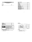
1
Contents
Language
Page
_______________________________________________________________
English
French
Spanish
0
TABLE OF CONTENTS
Topic
INVENTORY OF CONTENTS
QUICK SETUP
DETAILED SETUP GUIDE
BATTERY INSTALLATION
12 OR 24 HOUR TIME DISPLAY
TIME SETTING
FEATURES
MIN AND MAX TEMPERATURE
RESETTING MIN & MAX TEMPERATURE
ADDING ADDITIONAL THERMO-HYGRO SENSORS
VIEWING & OPERATING WITH MULTIPLE THERMO-HYGRO
SENSORS
MOUNTING
TROBLESHOOTING
MAINTENANCE AND CARE
SPECIFICATION
WARRANTY INFORMATION
1
Page
This product offers:
INSTANT TRANSMISSION is the state-of-the-art
new wireless transmission technology,
exclusively designed and developed by LA
CROSSE TECHNOLOGY. INSTANT
TRANSMISSION offers you an immediate update
(every 4 seconds!) of all your outdoor data
measured from the sensors: follow your climatic
variations in real-time!
2
12 or 24 Hour
Time Display
Outdoor
Temperature
(°F or °C)
Sensor signal
reception icon
Set/Channel
Button
FIGURE 1
Minimum/Maximum
& Plus Button
Max icon
Low Battery
Indicator
3
INVENTORY OF CONTENTS
1.
2.
3.
4.
5.
Wireless Temperature Station (Figure 1)
Wireless Temperature Sensor (TX29) and mounting bracket. (Figure 2)
3 each, 1/2” Philips screws.
One strip of double sided adhesive tape.
Instruction Manual and Warranty Card.
Figure 2
ADDITIONAL EQUIPMENT (not included)
1.
1 Philips screwdriver.
2.
4 Fresh “AA” 1.5VAlkaline Batteries.
4
QUICK SETUP
Hint: Use good quality Alkaline Batteries; avoid rechargeable batteries.
1.
Have the Wireless Temperature Station and temperature sensor 3 to 5 feet
apart.
Batteries should be out of both units for 5 minutes.
Place the batteries into the Temperature sensor first and next into the
Wireless Temperature Station.
4.
DO NOT PRESS ANY BUTTONS FOR 5 MINUTES.
In this time the Wireless Temperature Station and the temperature sensor will begin
to communicate with each other, and the display will show both the indoor
temperature and an outdoor temperature. If the Wireless Temperature Station does
not display both temperatures after the 5 minutes, please retry the set up as stated
above. After both indoor and outdoor temperatures are displayed for 5 minutes you
can place your temperature sensor outdoors, and set your time.
2.
3.
The temperature sensor should be placed in a dry, shaded area (ex: under the eve
of a roof). The temperature sensor has a range of 330 feet. Any walls that the
signal will have to pass through will reduce distance. An outdoor wall or window will
have up to 20 feet of resistance and an interior wall will have up to 10 feet of
resistance. Your distance plus resistance should not exceed 330 feet in a straight
line.
5
NOTE: Fog and mist will not harm your temperature sensor, but direct rain must be
avoided.
DETAILED SETUP GUIDE
BATTERY INSTALLATION - When one Temperature sensor is being used
1.
2.
3.
First, insert the batteries to the Temperature sensor (see “Temperature
sensor” below).
Within 2 minutes of powering up the sensor, insert the batteries to the
Temperature Station (see “Wireless Temperature station” below). Once the
batteries are in place, all segments of the LCD will light up briefly. Following
the indoor temperature and the time as 12:00 will be displayed. If they are
not shown in LCD after 60 seconds, remove the batteries and wait for at least
60 seconds before reinserting them. Once the indoor data is displayed user
may proceed to the next step.
After the batteries are inserted, the Temperature Station will start receiving
data signal from the sensor. The outdoor temperature should then be
displayed on the Temperature Station. If this does not happen after 2
minutes, the batteries will need to be removed from both units and reset from
step 1 and the signal reception icon is no longer shown.
6
TEMPERATURE SENSOR
1.
2.
3.
Remove the Battery Cover.
Observing the correct polarity, install 2 “AA”
Alkaline Batteries—make sure they do not spring
free, or start-up problems may occur.
Replace the Battery Cover.
WIRELESS TEMPERATURE STATION
Note: After the batteries are installed, DO NOT press any buttons. This may
interfere with the signals, causing temperatures to register incorrectly.
7
1.
2.
Battery
compartment
3.
Battery cover
Sensor signal
reception icon*
8
Remove the Battery Cover on
the back of the Wireless
Temperature Station.
Observing the correct polarity,
install 2 “AA” Alkaline
Batteries.
Replace Battery Cover.
•
•
*When the signal is successfully received by the Temperature Station, the
icon will be switched on. (If not successful, the icon will not be shown in LCD)
So the user can easily see whether the last reception was successful (icon
on) or not (icon off). On the other hand, the short blinking of the icon shows
that a reception is currently taking place.
If the signal reception is not successful on the first frequency (915MHz) for
45 seconds, the frequency is changed to 920MHz and the learning is tried
another 45 seconds. If still not successful the reception is tried for 45
seconds on 910MHz. This will also be done for re-synchronization.
SELECTING 12 OR 24 HOUR TIME DISPLAY
1.
2.
3.
Note:
•
•
4.
Press and hold the set/ch button for about 5 seconds.
“12h” will begin to flash in the TIME section of the LCD
Press the min/max/+ button to toggle between “12h” and “24h” time.
Selecting 12 hour time will automatically select °F as your temperature unit.
Selecting 24 hour time will automatically select °C as your temperature unit.
Press and release the set/ch button again to enter Time Setting.
9
TIME SETTING
1.
After exiting the 12/24 Hour Setting, the hour will begin flashing in the time
display.
2.
Press and release the min/max/+ button to select the desired hour.
Note: "PM" will appear to the left of the time display for PM hours. For AM hours,
that area will remain blank.
3.
Press and release the set/ch button again, and the minutes will begin to
flash.
4.
Press and release the min/max/+ button to select the desired minutes.
5.
Press and release the set/ch button to exit the SET UP mode.
Note: If no buttons are pressed for 10 seconds, the Wireless Temperature Station
will automatically return to the normal display.
FEATURES
MINIMUM AND MAXIMUM TEMPERATURES
1.
Press and release the min/max/+ button, “MIN” appears at the bottom of the
LCD and the recorded minimum temperatures are displayed.
2.
Press and release the min/max/+ button again to view maximum recorded
temperatures. “MAX” icon appears at the bottom of the LCD and the
maximum temperatures are displayed.
10
3.
Press and release the min/max/+ button once more to return to the current
temperatures.
RESETTING THE MINIMUM AND MAXIMUM READINGS:
User may reset the minimum and maximum temperature data to the current value
by the following step:
Press and hold the min/max/+ key for about 3 seconds to reset all the minimum/
maximum data of all channels and the indoor sensor to the current values in a
single action.
ADDING ADDITIONAL REMOTE SENSORS (OPTIONAL)
The WS-9021U is able to receive signals from 2 additional temperature sensors .
The following are instructions for the set-up of temperature sensor units with the
WS-9021U. These extra sensors can be purchased through the same dealer as this
unit.
1.
Remove all the batteries from the receiver and sensor(s) and wait 60
seconds. During these 60 seconds, press any button 20 times to discharge
any excess power.
2.
Insert the batteries to the first temperature sensor.
3.
Within 2 minutes of powering up the first sensor, insert the batteries to the
Temperature Station. Once the batteries are in place, all segments of the
11
LCD will light up briefly. Following the indoor temperature and the time as
12:00 will be displayed. If they are not shown in LCD after 60 seconds,
remove the batteries and wait for at least 60 seconds before reinserting
them.
4.
The outdoor temperature from the first sensor (channel 1) should then be
displayed on the Temperature station. If this does not happen and the signal
reception icon is not shown, after 2 minutes, the batteries will need to be
removed from both units and reset from step 1.
5.
Insert the batteries to the second sensor as soon as the outdoor temperature
readings from the first sensor are displayed on the Temperature station.
NOTE: You must insert the batteries into the second sensor within 45
seconds of reception of the first sensor.
6.
The outdoor temperature from the second sensor and the "channel 2" icon
should then be displayed on the Temperature station. If this does not happen
after 2 minute, the batteries will need to be removed from all the units and
reset from step 1.
7.
Insert the batteries to the third sensor as soon as the "channel 2" icon and
outdoor data are displayed on the Temperature station. Then within 2
minutes, the channel 3 outdoor data from the third sensor will be displayed
and the channel icon will shift back to "1" once the third sensor is
12
successfully received. If this is not happen, user shall restart the setting up
from step 1.
NOTE: You must insert the batteries into the third sensor within 45 seconds of
reception of the second sensor.
IMPORTANT: Transmission problems will arise if the setting for multiple sensors is
not followed as described above. Should transmission problems occur, it is
necessary to remove the batteries from all units and start again the set-up from
step 1.
VIEWING AND OPERATING WITH MULTIPLE REMOTE SENSOR UNITS
1.
To view the temperature of a different temperature sensor unit, press the
set/ch button to select to display the outdoor temperature of the different
sensors. A shift from one channel number to the next should be observed on
the right side of the OUTDOOR LCD.
2.
To view the Minimum/Maximum temperature: first select from which
temperature sensor to read data (indicated by the channel number).
Pressing and releasing the min/max/+ button will toggle through the minimum
and maximum indoor temperature, and the minimum and maximum outdoor
temperature.
13
MOUNTING
Note: To achieve a true temperature reading, avoid mounting in direct sunlight. We
recommend that you mount the temperature sensor on an outside North-facing wall
(under the eve of a house is ideal). The remote temperature sensor should be
placed in a dry, shaded area. The remote temperature sensor has a range of 330
feet. Keep in mind that the 330 feet is in open air with no obstructions and that
radio waves DO NOT curve around objects. Actual transmission range will vary
depending on what is in the path of the signal. Each obstruction (roof, walls, floors,
ceilings, thick trees, etc.) will effectively cut signal range in half.
Example: A wireless weather station receiver with a 330 feet range is mounted on
an interior wall, so that the signal has to pass through one interior wall, one exterior
wall, and across the 10 foot width of the room between the 2 walls. The first wall
will reduce the range to 165 feet, and the second wall will reduce the range to 87
feet. Factoring in the 10 foot room, this leaves a maximum of 77 feet of remaining
signal range.
This allowance is typically enough for a frame wall with non-metallic siding; however
certain materials can reduce range even further. Metal siding, stucco, and some
types of glass can reduce signal range by as much as ¾ or more, compared to the
14
½ reduction typical of most obstructions. It is possible to receive a signal through
these materials, however maximum range will be much less due to their tendency to
absorb or reflect a much larger portion of the sensor’s signal.
TEMPERATURE SENSOR
The Temperature has been designed to be hanged on a wall or free standing.
For Free standing:
Simply attached the stand to the bottom of the unit and
place onto a flat surface.
15
To wall mount:
1.
2.
3.
Remove the mounting bracket from the
temperature sensor.
Mount using either screws or adhesive tape.
Reattach the temperature sensor to the
mounting bracket.
WIRELESS TEMPERATURE STATION
1.
The Wireless Temperature Station comes with the table
stand attached to the back of the Receiver. If you wish to
use the table-stand, simply place the Wireless
Temperature Station in an appropriate location, and pull
out on the attached stand.
16
2.
To wall mount, push the table stand flat against the Wireless Temperature
Station (if it isn’t already flat). Fix a screw (not included) into the desired wall,
and place the Wireless Temperature Station onto the screw using the
hanging hole on the backside. Gently pull the Wireless Temperature Station
down to lock the screw into place.
TROUBLESHOOTING
NOTE: For problems not solved, please contact La Crosse Technology via e-mail or
phone, or visit our website, www.lacrossetechnology.com
Problem: The LCD is faint
Solution: Replace batteries
Problem: No outdoor temperature is displayed.
Solution:
1)
Bring any units from outside, inside and place the units 3 to 5 feet apart with
nothing in-between them.
2)
Remove the batteries from all units.
3)
Press one of the buttons on the Wireless Temperature Station display at
least 20 times to clear all memory. Verify that the display is blank before
proceeding.
17
4)
5)
6)
7)
Using good quality alkaline batteries, place the batteries back into the
outdoor temperature sensor; making sure they are installed according to the
diagrams in the battery compartment.
Taking care not to press any buttons, reinstall the batteries in the Wireless
Temperature Station according to the diagram in the battery compartment.
Do not press any buttons for at least 5 minutes after installing the batteries.
(This is to let the units establish a good connection.)
During the course of the 5 minutes an outdoor temperature should appear on
the display. You can now put your sensor(s) back outside.
MAINTENANCE AND CARE INSTRUCTIONS
•
Extreme temperatures, vibration, and shock should be avoided to prevent
damage to the units.
•
Clean displays and units with a soft, damp cloth. Do not use solvents or
scouring agents; they may mark the displays and casings.
•
Do not submerge in water.
•
Do not subject the units to unnecessary heat or cold by placing them in the
oven or freezer.
•
Opening the casings invalidates the warranty. Do not try to repair the unit.
Contact La Crosse Technology for repairs.
18
SPECIFICATIONS
Transmitting Frequency
915 MHz
TEMPERATURE MEASURING RANGES
Indoor
14.1°F to 139.8°F with 0.2°F resolution.
Outdoor
-39.8 °F to 139.8°F with 0.2°F resolution.
Transmitting range
Maximum 330 feet (100m) open space
TEMPERATURE CHECKING INTERVAL
Indoor
Every 15 seconds
Outdoor
Every 4 seconds
BATTERIES—(Alkaline recommended)
temperature Sensor
Wireless Temperature
Station
2 x AA, 1.5V
2 x AA, 1.5V
19
DIMENSION: (H x W x D)
Receiver
2.76 x 1.14 x 4.54 in (70 x 29 x 115.2 mm)
Temperature Sensor
1.50 x 0.83 x 5.05 in (38.2 x 21.2 x 128.3 mm)
Battery life
Up to 24 Months
WARRANTY INFORMATION
La Crosse Technology, Ltd provides a 1-year limited warranty on this product
against manufacturing defects in materials and workmanship.
This limited warranty begins on the original date of purchase, is valid only on
products purchased and used in North America and only to the original purchaser of
this product. To receive warranty service, the purchaser must contact La Crosse
Technology, Ltd for problem determination and service procedures. Warranty
service can only be performed by a La Crosse Technology, Ltd authorized service
center. The original dated bill of sale must be presented upon request as proof of
20
purchase to La Crosse Technology, Ltd or La Crosse Technology, Ltd’s authorized
service center.
La Crosse Technology, Ltd will repair or replace this product, at our option and at no
charge as stipulated herein, with new or reconditioned parts or products if found to
be defective during the limited warranty period specified above. All replaced parts
and products become the property of La Crosse Technology, Ltd and must be
returned to La Crosse Technology, Ltd. Replacement parts and products assume
the remaining original warranty, or ninety (90) days, whichever is longer. La Crosse
Technology, Ltd will pay all expenses for labor and materials for all repairs covered
by this warranty. If necessary repairs are not covered by this warranty, or if a
product is examined which is not in need or repair, you will be charged for the
repairs or examination. The owner must pay any shipping charges incurred in
getting your La Crosse Technology, Ltd product to a La Crosse Technology, Ltd
authorized service center. La Crosse Technology, Ltd will pay ground return
shipping charges to the owner of the product to a USA address only.
Your La Crosse Technology, Ltd warranty covers all defects in material and
workmanship with the following specified exceptions: (1) damage caused by
accident, unreasonable use or neglect (including the lack of reasonable and
necessary maintenance); (2) damage occurring during shipment (claims must be
21
presented to the carrier); (3) damage to, or deterioration of, any accessory or
decorative surface; (4) damage resulting from failure to follow instructions contained
in your owner’s manual; (5) damage resulting from the performance of repairs or
alterations by someone other than an authorized La Crosse Technology, Ltd
authorized service center; (6) units used for other than home use (7) applications
and uses that this product was not intended or (8) the products inability to receive a
signal due to any source of interference.. This warranty covers only actual defects
within the product itself, and does not cover the cost of installation or removal from
a fixed installation, normal set-up or adjustments, claims based on
misrepresentation by the seller or performance variations resulting from installationrelated circumstances.
LA CROSSE TECHNOLOGY, LTD WILL NOT ASSUME LIABILITY FOR
INCIDENTAL, CONSEQUENTIAL, PUNITIVE, OR OTHER SIMILAR DAMAGES
ASSOCIATED WITH THE OPERATION OR MALFUNCTION OF THIS PRODUCT.
THIS PRODUCT IS NOT TO BE USED FOR MEDICAL PURPOSES OR FOR
PUBLIC INFORMATION. THIS PRODUCT IS NOT A TOY. KEEP OUT OF
CHILDREN’S REACH.
22
This warranty gives you specific legal rights. You may also have other rights
specific to your State. Some States do no allow the exclusion of consequential or
incidental damages therefore the above exclusion of limitation may not apply to you.
For warranty work, technical support, or information contact:
La Crosse Technology, Ltd
2809 Losey Blvd. S.
La Crosse, WI 54601
Phone: 608.782.1610
Fax: 608.796.1020
e-mail:
[email protected]
(warranty work)
[email protected]
(information on other products)
web:
www.lacrossetechnology.com
23
Question? Instructions? Please visit:
www.lacrossetechnology.com/9021
All rights reserved. This handbook must not be reproduced in any form, even in
excerpts, or duplicated or processed using electronic, mechanical or chemical
procedures without written permission of the publisher.
This handbook may contain mistakes and printing errors. The information in this
handbook is regularly checked and corrections made in the next issue. We accept
no liability for technical mistakes or printing errors, or their consequences.
All trademarks and patents are acknowledged.
24