Download eo2 - form f3 _englisch
Transcript
Operating manual . . . . . . . . . . . . . . . . . . . . . . . . . . . . . . . . . . . 2 - 57 Betriebsanleitung . . . . . . . . . . . . . . . . . . . . . . . . . . . . . . . . . 58 - 113 Mode d’emploi . . . . . . . . . . . . . . . . . . . . . . . . . . . . . . . . . . . 114 - 134 Manuale per l’operatore . . . . . . . . . . . . . . . . . . . . . . . . . . . 135 - 155 Manual de instrucciones. . . . . . . . . . . . . . . . . . . . . . . . . . . 156 - 176 Instruktionsboken . . . . . . . . . . . . . . . . . . . . . . . . . . . . . . . . 177 - 195 -1- Forming WorkCenter EO2 – FORM F3 1 General safety instructions ................................................................................6 1.1 Explanation of the used safety symbols...................................................................... 6 1.2 Dangers and their prevention ....................................................................................... 6 1.3 Necessary qualifications............................................................................................... 7 1.4 Intended use .................................................................................................................. 8 1.4.1 Approved use ............................................................................................................................... 8 1.4.2 Tools ............................................................................................................................................ 9 1.4.3 Improper use ................................................................................................................................ 9 1.4.4 Limits of operation...................................................................................................................... 10 1.4.5 Personal safety protection ......................................................................................................... 11 1.4.6 Working positions....................................................................................................................... 11 1.5 Structural changes at the machine ............................................................................ 12 1.6 Safety stipulations during the lifetime phases of the machine ................................ 12 1.6.1 Transport, setting up and installation......................................................................................... 12 1.6.2 Normal operation ....................................................................................................................... 13 1.6.3 Maintenance, repair and trouble shooting ................................................................................. 14 1.6.4 Work on electrical equipment..................................................................................................... 16 1.6.5 Work on hydraulically equipment............................................................................................... 17 1.6.6 Hazard due from residual energy............................................................................................... 17 1.6.7 Disposal, dismantling ................................................................................................................. 18 1.7 Emission ...................................................................................................................... 19 1.7.1 Noise .......................................................................................................................................... 19 1.7.2 Vibrations ................................................................................................................................... 19 1.7.3 Electromagnetic compatibility .................................................................................................... 19 1.8 Safety devices ............................................................................................................. 20 -2- 2 Description of machine .....................................................................................21 2.1 Description of the control elements........................................................................... 21 2.2 Technical data ............................................................................................................. 23 EC – Declaration of conformity................................................................. 24 3 4 Transport, Setting up and Installation..........................................................25 3.1 Packing ........................................................................................................................ 25 3.2 Transport of the machine............................................................................................ 25 3.3 Setting up..................................................................................................................... 27 3.4 Electrical installation................................................................................................... 27 3.5 Checks before start up the machine .......................................................................... 28 3.6 Checks after the first start .......................................................................................... 29 The EO2–FORM Connection ............................................................................30 4.1 Introduction ................................................................................................................. 30 4.2 EO2-Form Features ..................................................................................................... 30 4.3 The EO2-FORM connection: ....................................................................................... 32 4.4 Safety notes to the EO2-Form assembly ................................................................... 33 4.4.1 EO Tube Fittings are Safe High-Pressure Connections. ........................................................... 33 4.4.2 General Safety notes ................................................................................................................. 33 4.4.3 Safety Instructions for Assembly................................................................................................ 35 4.5 EO2 FORM assembly instructions ............................................................................. 36 4.5.1 General ...................................................................................................................................... 36 4.5.2 Material Combinations, Tube Preparation ................................................................................. 37 4.5.3 Tube preparation chart – series L .............................................................................................. 38 4.5.4 Tube preparation chart – series S.............................................................................................. 39 4.5.5 Tube forming with EO2-FORM F3 ............................................................................................. 40 4.5.6 Assembly check, Installation...................................................................................................... 42 -3- 5 4.6 Tool indication............................................................................................................. 43 4.7 Possible faults and their removal............................................................................... 44 Maintenance ..........................................................................................................47 5.1 Spare part service ....................................................................................................... 47 5.2 Regular maintenance of your machine ...................................................................... 48 5.3 Maintenance of hydraulic plants ................................................................................ 50 5.3.1 Check the hydraulic fluid level ................................................................................................... 50 5.3.2 Hydraulic oil change................................................................................................................... 51 5.3.3 Change of the reflux filter........................................................................................................... 52 5.3.4 Check and change of the high pressure filter ............................................................................ 52 5.3.5 Change of the hydraulic hoses .................................................................................................. 53 5.3.6 Hydraulic oil................................................................................................................................ 53 5.4 5.4.1 5.5 5.5.1 Electrical circuit components..................................................................................... 54 Instruction to put in the battery (SPS – Control) ........................................................................ 54 Maintenance- and Service plan .................................................................................. 55 Service plan ............................................................................................................................... 56 Appendix / Anhang .................................................................................................................195 Hydraulic circuit diagram / Hydraulikschaltplan .....................................................................................196 Elektric circuit diagram / Elektroschaltplan ............................................................................................197 -4- Important remarks concerning the operating of the machine The most important preconditions to avoid injury to persons, and damage to materials, when working with the machine is the strict observance of the requisite safety rules and other statutory requirements for the operating of the machine. The essential information which is required for safe operating of the machine is contained in this operating manual. This operating manual in particular the safety instructions must be observed by all persons who work in any way with parts of the system, or with the complete system. Additionally, the rules and regulations which apply at the operating location must be observed. -5- 1 General safety instructions 1.1 Explanation of the used safety symbols In this manual are used symbols for the emphasis of particularly important sections. All sections, which are countersigns with a symbol must be considered particularly. NOTE! i This symbol is used to draw attention to sections containing particularly important information concerning processes, methods and the use of facilities, etc. DANGER! This symbol is used wherever insufficient care can result in danger to life and limb. WARNING! This symbol is used wherever any deviation from the described procedure, or incompetently completed work, can result in damage to the machine. DANGER OF DEATH! This symbol is used to emphasize sections in which persons are warned of electrical voltage and the associated dangers. 1.2 Dangers and their prevention The combined action of the machine, controls, tools and protective equipment as well as the behaviour of the operator according to the safety rules are indispensable for safe working at he machine. The majority of accidents in conjunction with machines are injuries caused by closing tools. Most of these injuries are injuries of fingers and hands. The risk of being injured not only exists for the operator himself, but especially for other persons. -6- 1.3 Necessary qualifications The machine was designed and built on the basis of a risk analysis and under consideration of all relevant harmonised standards as well as further national standards and technical specifications. The machine thus conforms to the current level of technology and guarantees the highest possible degree of safety. This level of safety can only be achieved in practice if all necessary measures are observed in dealing with the machine. It is therefore part of the duty of care of the machine's operator to plan these measures and check that they are executed correctly. In particular the operator must ensure that • the machine is used only as prescribed • the machine is operated only in a fault-free, operational condition and in particular the safety devices are regularly checked to ensure that they function as stipulated • the operating manual is always legible and is available in full at the machine's location • all safety instructions and warnings on the machine are visible and legible and are not removed. The machine may only be operated by persons who have been specially trained, briefed and authorised. These persons must be familiar with the operating manual and act in accordance with it. The respective areas of authority of the operating personnel must be clearly defined. Trainee operating personnel may at first only work on the machine under the supervision of an experienced person. Successful completion of the induction period should be confirmed in writing. All control and safety devices must be operated only by persons who have been suitably instructed. -7- 1.4 Intended use With the intended purpose we wish to define the approved use of the machine to distinguish it from improper use. Please adhere exactly to the approved use in order to prevent accidents. 1.4.1 Approved use The machine is an axially working deforming machine and serves excluding the preparation of tube ends for the EO2 - screw connections according to DIN EN 8434-1. All indicated performance data, as well as the other technical specifications of the machine must be kept without exception. Another or beyond going use is not considered than intended purpose. The manufacturer is not responsible for damages which are happened by inadequate operating NOTE! i The intended purpose also includes the observance of all notes and requisite safety regulations from the manual and the observance of the inspection and maintenance work. The operator of the machine must ensure that the machine and all its parts only used in keeping with their intended purpose, and that the machine is only operated in a faultless functional condition. The user of the machine is under obligation to immediately switch off the machine in the event of any safety relevant changes to the machine or its operating behaviour, and to immediately notify the operator of such disruptions. DANGER! Persons can be injured, and the machine can be damaged, if care in the operating of the machine is insufficient or if the machine is not used in conformity with its intended purpose. -8- 1.4.2 Tools Only such tools are permitted, that have been made to our specifications especially concerning • construction material • heat treatment • geometry The tools are to be installed with the enclosed handling devices surely in the machine, so that fall out of tools is impossible. 1.4.3 Improper use The following types of improper use are known to us: • Misuse – Use the machine contrary to the approved use, especially concerning: - use • Exceeding limits of operation – Use outside the limits of operation as detail in chapter 1.4.4 • Failure to follow the operating instructions – Use contrary to the stipulation in the operating instructions concerning: - safety - installation - operating - maintenance • Faults – Use with obvious faults, especially on - machine - tool - controls - electrical and hydraulically supply -9- 1.4.4 Limits of operation The following obligatory limits of operation apply for the machine and consist of three parts. • General limits of operation which apply for all machines - • environmental conditions Type-specific limits of operation which only apply for your type - mechanical energy supply - nominal size • Customer-specific limits of operation which only apply for your particular use - electrical supply Environmental conditions • working temperature +10... +50 º C • storage temperature - 10... +70 º C • relative humidity max. 90%, non-condensing Mechanical energy supply (operating instructions / technical data) • pressure Nominal size of rivet (operating instructions / technical data) • tubing dimensions Electrical energy supply (operating instructions / technical data) • nominal voltage • nominal current per phase • frequency - 10 - 1.4.5 Personal safety protection All users are obliged to wear at least the following personal safety protection while working with the machine • closely fitting work clothing • safety shoes During maintenance work on electrical equipment we also stipulate non-conductive shoes. WARNING! Risk of eye injury or electrical shock. Always wear the prescribed personal safety protection. 1.4.6 Working positions While operating, the working position of the operator is located directly in front of the machine. The control is arranged in such a way that it can serve from operators location. The foot panel to start the process must be positioned outside the danger zone of the machine. No special working positions are recommended for installation and maintenance. - 11 - 1.5 Structural changes at the machine Arbitrary structural changes at the machine without permission of the manufacturer are forbidden. All planned changes must be authorised in writing by the manufacturer. Use only original replacement parts / original wearing parts / original accessories. These parts are specially designed for the machine. With bought-in parts there is no guarantee that they have been designed and built to comply with the stress and safety requirements of the machine. Parts and special fittings which were not supplied by us are also not approved by us for use in/on the machine. 1.6 1.6.1 Safety stipulations during the lifetime phases of the machine Transport, setting up and installation The machine may be transported and installed only by authorized and trained personnel, which can know the manual and work afterwards! For the transport and installation work the following points are to be considered: • Check on receipt whether you have received the machine complete and undamaged. Inform the manufacturer immediately if you have any complains. Never start the machine before all defects have been rectified. • Lift the machine only at the lifting points provided. Use only lifting gear in good condition with sufficient lifting capacity for this purpose. Observe the weight details • Check the electrical and hydraulically devices for damage before you switch on the machine. • Switch the machine current and pressure-free, before you shut-down and dismantle it. - 12 - 1.6.2 Normal operation The machine may only be operated by authorized and trained personnel, which can know the manual and work afterwards! Before starting familiarise yourself sufficiently with • the machine's operating and control elements • the equipment of the machine • the function of the machine • the safety devices of the machine • the immediate environment of the machine Before each starting the following activities are to be performed: • Check to make sure that all safety devices are fitted and functioning • Check the machine for visible damage; any defects found must be corrected immediately or reported to the supervisor - the machine may only be operated if it is free of faults • Make sure that only authorised persons remain within the operating area of the machine and that no other persons are endangered when the machine is started up • All objects and other materials which are not required for operation of the machine must be removed from the machine's operating area During the operation the following points are to be considered: • During the operation of the machine no safety devices may be removed or set out of function. • The operation mode of the machine may be changed only by authorized persons and in agreement with the intended use • During operation the machine may be served only by a person. If aids are necessary with large work pieces, you must hold both hands outside of the danger area of the work piece. - 13 - • Only use genuine EO2-Form tooling provided by Parker. • Do not operate the machine without tooling. • After switching off the machine the operating personnel must wait until all mobile parts to stand still and the function lights are expired, - only then the machine may be left. 1.6.3 Maintenance, repair and trouble shooting The machine may only be repaired by authorized and trained personnel, which can know the manual and work afterwards! The servicing tasks defined in the operating manual - tuning, cleaning, lubrication, maintenance, inspection, ... - must be performed when due. Before performing the servicing work, you must observe the following: • Switch off the central power supply by the main switch, lock the main switch and put up a warning sign prohibiting switching it on again. • Secure all pressure-free switched components against unintentional restarting. • Guarantee that for the exchange of larger machine parts an appropriate lifting devices and load suspension devices are present. • Lock the entrance to the work area of the machine and guarantee that no unauthorized persons in the work area of the machine. - 14 - • Block off access to the operating area of the machine. • Exchange all not perfect machine parts immediately. • Use only original spare parts. • Guarantee that for all groundwater-endangering materials (oils, cooling agents and ae.) suitable receptacles are available. After completing the servicing work and before starting the machine, you must observe the following points: • Double-check all previously loosened screws to make sure they are tightly secured. • Check that all previously removed protective devices, covers, container lids, screens, filters, .... have been replaced correctly. • Make sure that all previously used tools, materials and other equipment are removed from the operating area. • Clean the operating area and remove any liquids or similar substances which may have leaked out. • Make sure that all the machine's safety devices are functioning properly again. • Do not operate the machine without forming head. - 15 - 1.6.4 Work on electrical equipment The machine is powered with electricity. Certain safety measures have to be observed when dealing with electrical energy. • All work on the System’s electrical power supply must only be completed by a qualified electrician. • If your company does not employ a works electrician, then a correspondingly trained person must be commissioned with the work. • By disturbances in the electrical power supply switch off the plant immediately. • Before beginning of all work with parts of the plant, which are supplied with electricity, switch off the main switch and secure them against unexpected restarting. • All persons who are not authorized to complete work on the System’s electrical power supply must be barred from gaining access to the inner space of the control housing. DANGER OF DEATH! Involvement with electrical power entails a danger of death! The system must first be made current less before any work on the System can commence. - 16 - 1.6.5 Work on hydraulically equipment The machine is powered by hydraulically pressure energy. Certain safety measures have to be observed when dealing with hydraulically or pneumatically pressure energy. • All work on the System’s hydraulically power supply must only be completed by a qualified specialist. • If your company does not employ a works mechanic, then a correspondingly trained person must be commissioned with the work. • The system must first be made pressure free before any work on system sections and pressure pipes can commence. • During preventive servicing during repair work, the hose pipes should always be exchanged also - even if there is no noticeable damage yet. See also the instructions of the hose manufacturers. DANGER! Under high pressure withdrawing liquids can penetrate the skin and cause heavy injuries. i 1.6.6 NOTE! With injuries by hydraulic fluids consult a physician immediately, it exists risk of infection ! Hazard due from residual energy Note that various forms of energy can still be present after the machine has been switched off or has come to a standstill - for example: • in hydraulic pressure pipes and pressure receivers • in electrical lines and condensers - 17 - 1.6.7 Disposal, dismantling Disposal of the components exchanged, such as seals, filter cartridges and particularly hydraulic oil and lubricants, is made according to the local waste disposal regulations and the environmental protection laws applicable in the country of use. The mineral oils suggested by us can be recycled, depending on the degree of contamination and decomposition. Refer also to the manufacturer’s specifications. If the machine has reached the end of its useful life, safe and correct disposal must be ensured for its dismantling, particularly of substances and parts hazardous to the environment. These include • lubricants • hydraulic oil • plastic • batteries - 18 - 1.7 Emission The following data concerns emissions from the machine. They correspond to the relevant stipulations of the EEC Directives and appropriate standards for the machine safety. i 1.7.1 NOTE! Observe all other safety work and accident prevention regulations. Noise The sound pressure level of noise created by the machine at the working place of the operator is lower than 70 dB (A). 1.7.2 Vibrations No noticeable vibrations are emitted by the working of the machine. Anti-vibration measures are not necessary. 1.7.3 Electromagnetic compatibility Electromagnetic compatibility of the machine corresponds to EEC Directive 89/336/EWG. • Electromagnetic radiation produces by the machine is adequately shielded. • Immunity of the machine against electromagnetic radiation is sufficient to meet official requirements. - 19 - 1.8 Safety devices The safety devices serve for to security and health of the personnel and protect the machine against damage. The correct function of these safety devices can become of vital importance. The machine is equipped with the following safety devices: • Lockable main switch at the switchgear cabinet of the machine. With the help of the main switch the machine will be brought to the net and / or separated from the net depending the position of the main switch. Turn the main switch into the desired position. • Emergency Stop button at the control console of the machine. The Emergency Stop button serves for the process interruption. Operate the Emergency Stop, by pressing the red button. If the danger is repaired, put the Emergency Stop back again by pulling out the red button. Emergency Stop button Main switch WARNING! Before start-up of the machine it is to be guaranteed that all safety devices are attached and functional. - 20 - 2 Description of machine 2.1 Description of the control elements 3 7 6 5 4 8 1 2 - 21 - Pos. Component Labeling 1 Piece counter 2 Main switch 3 Piece counter 4 Press button OFF 5 Press button ON Function 1 = ON 0 = OFF Turn the Main switch into desired position. Press the button, in order to reset the piece counter. Press the button (OFF), in order to switch off the machine. Press the button (ON), in order to switch on the machine. The button (ON) lights up, by switched on machine. Press the button (RESET), in order to start the automatic tool recognition. Press and hold the button (RESET) up to lighting up of the button. A lighting up of the button (RESET) signals starting ability of the machine. The button (RESET) blinks slowly, if 6 Press button RESET • the filling level of hydraulics is too low! • the temperature of hydraulics is too high! The button (RESET) blinks fast, if • no tools are inserted into the machine! Press the button (RESET), in order to restart the hydraulic by no activity of the machine ( 5 minutes )! Press the button (START) in order to start the production run of 7 Press button START the machine. Press and hold the button(START), until the tube is clamped. 8 Press button EMERGENCY Press the EMERGENCY STOP button only in emergency STOP situations. - 22 - 2.2 Technical data Deforming achievement: Steel tube ST 37.4: from 6 x 1mm to 38 x 7mm/42 x 4mm Stainless steel tube 1.4571: from 6 x 1 mm to 38 x 5mm/42 x 3mm Cycle time: 15 to 20 seconds Measurement: Length: 600 mm Width: 660 mm Height: 1150 mm Weight: approx. 300 kg Hydraulic: Working pressure: 800 bar Nominal pressure: 250 bar Flow rate: 3,3 l/min Duration of connection: 100% Capacity of the tank: 13 Litre Kind of oil: HLP 46 Electrical control Drive power: 1,1 kW Nominal voltage: 400 V AC 3 N / PE / 50 Hz Cable cross section of main cable: 5 x 2,5 mm² Nominal current of main fuse: max. 25 A - 23 - EC – Declaration of conformity in keeping with the European Machinery Directive (98/37/EC), appendix II A Hereby declares the manufacturer, Parker Hannifin GmbH Am Metallwerk 9 33659 Bielefeld that the following product, Forming WorkCenter EO2 – FORM F3 corresponds to all fundamental safety and health requirements of the above specified EC directive. The product is conform with the following EC directives: 73/23/EWG ECC-low voltage directive 89/336/EWG ECC-electro-magnetic compatibility The product is conform with the following harmonized standards: EN 12100, Part 1and Part 2 EN 294 EN 349 EN 982 Safety of Machines, Equipment and Plants Safety margin against achieving danger places with upper member masses Minimum distances for the avoidance of squeezing of the body parts Safety of Machinery - Safety Requirements for Fluid Power Systems and Their Components - Hydraulics EN 418 Safety of Machines, Emergency Stop Equipment EN 60204, Part 1 Safety of Electrical Equipment for Industrial Machines The declaration of conformity is void if changes are made to the construction of the machine which affect the technical specifications and prescribed use as indicated in the operating manual, which essentially change the machine! The signing person is authorized for signing this declaration in representation of the manufacturer. Bielefeld, 12.12.2007 _______________________ (Signature / Stamp) - 24 - 3 Transport, Setting up and Installation 3.1 Packing By distribution the machine will be packed and transported on a special wood pallet . The machine can be transported with the help of a crane. • Keep all parts of the original packaging for a possibly necessary return transport. • For the return transport is only the original packaging to be used. Separate before the dispatch all attached cables and draw/mobile parts. • 3.2 Attach possibly intended transport locks. Secure all parts approximately slip and for damage Transport of the machine • In the case of transport with fork-lift truck (without original packaging and / or pallet), the forklift truck may be set only in the guide rails in the machine basic frame. Guide rails WARNING! Take up the machine only at the intended points. The machine is top-heavy. An centric setting of the fork-lift truck could lead to falling of the machine. - 25 - • In the case of transport with crane, take up the machine only at pick up points, with four equal length conveyor belts. Conveyor belts Pick up points - 26 - 3.3 Setting up • Put the machine on the four wheels and tighten the parking brake, in order to ensure safe conditions of the machine. Parking brake NOTE! i The machine may be operated only in closed and dry areas. The underground should be even and horizontal. Within a workshop the machine can be pushed on the wheels to the different places of work. 3.4 Electrical installation The machine is normally supplied with a 5m length of connection cable. A 3-phase and ground connection is required. A 15 amp main fuse is recommended but no more than 20 amp. Attach the machine with the electric plug to the electrical current supply (400 V, 50Hz). NOTE! i Before power is applied, the voltage of the power supply should be checked against the voltage specified of the machine (see identification plate or circuit diagram). - 27 - 3.5 Checks before start up the machine Before the first start up of the machine and before the first employment in production the following points are to be considered: • Check the level of the hydraulic aggregate at the oil level indicator and if necessary fill hydraulic oil (HLP 46) into the tank! • Check if all necessary electrical connections are plugged and the plugs sit firmly! Power supply plug Oil level indicator - 28 - 3.6 Checks after the first start • Turn the main switch to the right on position "On". • Press the button "I" (ON). The button lights up, if the machine is ready for use. • Before pressing the button "R" (RESET) the tools must be inserted into the machine. Otherwise the button "R" (RESET) flashes fast. • Press the button "R" (RESET). The machine accomplishes an automatic tool recognition. Keep pressed the button until the button lights up. Malfunctions of the machine: • Pull the power supply plug. Turn the phase changer around 180º at the power supply plug with a screwdriver. Phase changer WARNING! If machine functions are blocked, switch off the machine immediately! Long operation of the pump in false direction of rotation leads to the total failure of the pump! - 29 - 4 The EO2–FORM Connection 4.1 Introduction EO2-FORM is the new high pressure formed tube Generation of the Tube Fittings Division Europe. As with EO2-Plus, it is designed in to eliminate leakage in all fluid systems, by using elastomeric sealing systems. The common feature of all EO2-FORM connections are the EO2 seal elements (Dry Technology) as well as the new cold forming process, that gives extreme rigidity and low tightening torques. The seals are now also available in FPM (e.g. Viton®) for applications with higher temperatures or aggressive media. Through EO2-FORM, elastomeric sealing technology is made available even where bite-type connectors are not popular, like in hydraulic presses, cranes, lifts or ship canal locks. Compared to welding or brazing, the EO2-FORM process is faster and easier. It does not require special tube treatment, heating or chemicals. EO2-FORM is designed for metric tube and fully interchangeable to the complete Ermeto Original product range according to ISO 8434-1 / DIN 2353. EO2-FORM is available in “L“- and “S“-Series. 4.2 EO2-Form Features Elastomeric sealing The high volume elastomeric seal assures a hermetically sealed tube joint. It is located in between the inner cone of the fitting body and the tube surface, thus blocking the only possible leak path. Due its large cross section, the seal effectively compensates for all manufacturing tolerances between the tube and fitting cone. The sealing effect is pressure supported which makes the EO2-FORM fitting ideal for high pressure applications. The static compression also eliminates air-ingress into the fluid system in vacuum conditions. Elastomerically sealed EO2-FORM fittings do not require any retightening even in heavy-duty applications. Seal extrusion is prevented by proper housing without gaps or dead volume areas. The sealing lip is bonded to a metallic support ring. - 30 - Cold-formed tube The cold-forming of the tube is carried out by the EO2-FORM machine. Machine operation and tool set-up are optimised for short cycle times, which makes the process easy and fast. The tube is connected when the sealing ring is fixed and the nut is tightened. The working contact area of the EO2-FORM connection is the flat front surface of the metallic support ring which is made of heat-treated, high-strength steel. This provides superior mechanical strength without settling, loosening or need for re-tightening. Advantages & Benefits of the EO2-Form fitting system Highest Pressure Performance: Due to the application of even better materials combined with the special processing of individual components, EO2-FORM can be used in applications of up to 800 bar (S series) and 500 bar (L series). EO-FORM considerably exceeds the DIN/ISO requirements and guarantees a 4-fold design factor. Thanks to the higher pressure levels, less expensive “L“ series fittings can now be used instead of the heavier “S“ series, which also is of benefit in limited or tight space applications. Sealing capability: The high volume elastomeric seal forms the primary sealing element, thus assuring leak-free sealing. Even low-viscosity media such as water or gas are hermetically sealed. Hydraulic systems therefore do not “sweat“ at the fitting joints. Universal: The EO2-FORM machine can cold-form all common steel tubes used in hydraulic systems (the EO2-FORM process also allows the use of stainless steel and exotic materials such as CuNiFe; please ask for separate catalogue). EO2-FORM tools cover metric tube from 6 to 42 mm OD. Thin wall tube of 1 mm wall thickness can be processed, too. Superior vibration resistance: The new EO2-FORM process achieves a smooth structural transformation of the tube wall allowing superior vibration resistance. Durability: The elastomeric seal does not require any re-tightening even after years of operation under severe working conditions. Efficient: Compared to welding or brazing, EO2-FORM is much less time consuming. Special tube preparation and finishing are not necessary. Forming uses only a fraction of the energy needed for brazing or welding. Quality: Tube clamping and tooling are fully automated. Therefore, high and consistent quality is achieved without manual adjustment. - 31 - Noise Reduction: Compared to other forming methods, the EO2-FORM process results in a smooth inner contour of the tube that does not allow the accumulation of air, dirt or other sources of trouble. Less pressure drop, heat and noise is created. Re-usability: EO2-FORM connections can be disassembled and reassembled many times. There is no wear or widening of the vulnerable fitting inner cone. Approved: Both, EO2 high pressure tube fittings and the EO2-FORM process are tested and approved by independent organisations such as Germanischer Lloyd and Det Norske Veritas (DNV). Small bending radii: The compact clamping device and special dies are suitable for forming short tube ends. Clean: The EO2-FORM process is environmentally clean and safe. As no heat is used, hazards from chemicals, fumes or heat do not occur. 4.3 The EO2-FORM connection: Screw nut Fitting body Tube EO2 – Seal (DOZ) - 32 - 4.4 4.4.1 Safety notes to the EO2-Form assembly EO Tube Fittings are Safe High-Pressure Connections. A carefully assembled EO fitting will provide a sealed joint until the tube bursts. Experience has shown that break-downs, tightening-up and leaks can be avoided by following the safety instructions. Please check your fitting procedures. 4.4.2 General Safety notes • EO tube fittings are intended for connections for fluid applications solely. • Observe tube recommendations. Non-standard materials or tolerances lead to incorrect fitting. • Do not use bearing balls, fitting pins or tapered pins instead of EO plugs (VKA) as blanking parts for 24º cones. • Do not assemble progressive rings and functional nuts on selfmade standpipe stud ends. There is a risk of false assembly with the result of connection shear under load. • The use of steel cutting rings for stainless steel tubes or other unauthorised tool combinations leads to incorrect assembly. • Tube connection and fitting body once assembled, should remain together. Fitting body is to be used only once for preassembly. • Air bleeding of tube fittings which are under pressure can be lethal. • Tube under tension can lead to vibration failure. Tube length and bend angles are to be adhered to precisely. Fix tube lines with tube clamps. - 33 - • Tubes are not to be clamped to one another but to suitable fixed points. Plate brackets, cable connections and fixing elements are not suitable. Tubes are not mountings on which to integrate other components e.g. filters, ventilators or shutoff valves. • Under- and over tightening of fittings during assembly reduces the capacity for withstanding pressure and vibration loads and therefore reduces the life of the tube fitting. Leaks from the tube can occur under these circumstances. • When dismantling/transporting and re-assembling, make sure that no dirt enters the system, that the connection elements (threads, sealing surfaces) are not damaged, seals are not lost and tubes are not bent or flattened. We recommend the use of suitable protective caps. • Prevent oscillation, pressure surges and inherent strain by using flexible hoses for example. • Disassembled fittings are to be checked for accuracy and damage and replaced if necessary. • Do not use hand cutters or tube cutters. • Impurities and splinters can lead to disruptions in the system and leaks. • The operating parameters given (e.g. pressure, temperature, medium compatibility) are to be adhered to. • Avoid flow rates > 8 m/s. The resulting forces are high and can destroy the tube lines. • Relevant guidelines (e.g. CE, ISO, BG, TÜV, DIN) are to be observed. • Weld fittings are manufactured out of weld able materials. No other fittings are suitable for welding. • EO Niromont is a high-performance lubricant. The use of other lubricants generally leads to an increase in assembly force. • The tools and lubricants recommended by EO guarantee safe assembly. • If tools and assembly equipment of other manufacturers are used, the function and assembly results have to be checked. • Fittings are to be handled with care. - 34 - • Tubelines need to be adapted tension free of the relevant connectors before assembly. An easy turning of the nut is required for the complete thread length. Otherwise leakage can occur. In extreme cases with additional vibrations tube cracks can occur. • Vibrations have to be intercepted by tube clamps. Independent vibration units need to be separated with hoses. Otherwise tube cracks can occur. i 4.4.3 NOTE! In case of doubt please contact your Parker representative! Safety Instructions for Assembly During a progressive ring and EO-2 fitting assembly the tube has to bottom up in the stud or in the tool. Without tube bottoming the ring cannot bite sufficiently. Under load the connection can fail due to tube shear. Incompletely assembly will reduce the pressure and vibration capability of a fitting. It can reduce the life cycle time of a connection and leakage can occur. In extreme cases the connection can fail due to tube shear or tube crack. Presented progressive ring fittings need a final assembly according to assembly instructions. After opening a tube connection, the unit has to be retighten with the same force used during prior assembly. Under tightening can result in leakage and can reduce the vibration capability. Over tightening can reduce the possibilities of repeated assembly. In extreme cases the components can be destroyed. Stainless steel progressive ring fittings have to be presented in hardened tools. Otherwise the connection may fail under load due to tube shear. - 35 - 4.5 4.5.1 EO2 FORM assembly instructions General - 36 - 4.5.2 Material Combinations, Tube Preparation - 37 - 4.5.3 Tube preparation chart – series L - 38 - 4.5.4 Tube preparation chart – series S - 39 - 4.5.5 Tube forming with EO2-FORM F3 - 40 - - 41 - 4.5.6 Assembly check, Installation - 42 - 4.6 Tool indication Each tool kit (forming pin and clamp die set) is marked for identification with a Parker code and the appropriate tubing size. Clamp die set Forming pin NOTE! i We recommend to use only the correct tools for the appropriate tubing size. This will extend the service life of the tools and will ensure the correct assembly of your transformed tubes. - 43 - 4.7 Possible faults and their removal Trouble 1. Machine runs, but no movement possible 2. Forming pin cannot be set in the machine Cause Solution Wrong direction of rotation (phases) at the CEE plug (> hydraulic pump runs the wrong direction) Fixing pin is not centered Turn phases at the CEE - plug with screwdriver Center fixing pin and secure with set-screw Use correct tubing tolerances. Tubing outside diameter too large examine tubing tolerance after DIN 2391/ISO 3304 Select correct form stamp for Wrong form stamp and /or tube wall thickness outside diameters and tubing wall thickness 3. Tube cannot be insert into forming pin tubing Tube was not deburred carefully Deburr and remove splinters Tube end oval Examine tube for oval shape Tube not carefully cleaned Clean the tube Forming pin dirty Clean forming pin Check tubing outside diameter Tubing outside diameter too small tolerance according to 2391/ISO 3304 4. Tube slips Surface of the clamp dies is dirty Clean with wire brush/solvent Surface of the clamp dies is worn Exchange clamp dies Tubing surface unsuitable remove paint, rust, etc. - 44 - DIN Trouble Cause Solution 1. Unscrew form head front part (mark position before). 2. Take forming pin with tube. 3. Screw on form head front part, 5. Tube cannot be put out of the machine and sticks in the form Tube slid in the clamp dies tighten it until marking. 4. Exchange forming pin. 5. stamp Clean clamping dies and replace when worn out. 6. Lubricate the tubes inside and outside in the future 1. Switch off the machine (0) 2. Switch on the machine (I) 3. Press RESET button (R) 4. Chuck jaws open 5. Put forming pin with tube into 6. Tube cannot be put out of the machine and sticks in the form stamp clamp Sometimes dies do not Forming pin disconnects from bayonet fixing (tube was turned against the clockwise direction in the form stamp) open the bayonet fixing and turn it in the clockwise direction again 6.Press start button and redo the forming procedure 7. Take out the tube after opening the clamp dies 8. When the clamp dies do not open, forming head must be unscrewed, see line 5. Forming pin used for to large tube wall select correct forming pin for the thickness 7. Tube appropriate tube wall thickness end not Forming pin used for other material completely formed out select correct forming pin for steel/stainless steel Press tube against tube stop. Tube not pressed against tube stop Deburr tube end carefully Examine tube for oval shape. - 45 - Trouble Cause Solution 8. Roughness of the Forming pin dirty sealing surface Clean forming pin too large Forming pin worn, no lubricant uses Lubricate tube inside and outside. Exchange forming pin Leave Temperature too high cooling the machine approx. 5 min 9. RESET - button flashes slowly Check the oil level; if necessary Oil level too low 10. RESET - button refill hydraulic oil No tooling in the machine flashes fast; START Insert the forming pin correctly; button cannot be operated Insert a tool into the machine Forming pin disconnects from bayonet fixing and through turn right the forming pin, in order to lock the forming pin in the bayonet fixing - 46 - 5 Maintenance This chapter will help you for maintenance your EO2 - Form F3 machine. If you need additionally assistance, please phone the next Parker dealer and indicate type and serial number of your machine and you will get help straight away. DANGER OF SEQUEEZING! By maintenance and repair work, switch off the main switch and secure it against restarting! 5.1 Spare part service We can support you always with original - spare parts, which ensure a perfect function of your system. We make expressly attentive to the fact that spare parts and accessories, which we did not deliver, are not checked and approved by us. The installation and / or the use of such products can change structionally given characteristics of your system negatively and impair the active and / or passive security. WARNING! For damage by using no original – wearing parts and accessories legal liability and guarantee are impossible to give. - 47 - 5.2 Regular maintenance of your machine The maintenance of your EO2 - FORM F3 machine is held small. Consider the Maintenance- and Service plan! Only good tool status, clean forming pin and clap dies guarantee a correct operating of your machine. The forming system of the machine must be kept free by contamination (particles and burr remainders). Clean they the system with a clean rag or exhaust it regularly. Head Do not operate the machine without tooling! Forming system Forming cylinder with bayonet fixing Do not operate the machine without forming head! - 48 - DANGER! Cleaning work at the machine only with switched off machine. NOTE! i Use no compressed air because injecting from air will possibly lead to the consequence that metal particles can settle in the accommodations and on the sliding surfaces of the guides. For the better cleaning of the forming system unscrew the head with the help of a rake key. Check the tools regularly (after approx 50 farming’s) for contamination and wear and tear . Replace worn tools ! - 49 - 5.3 Maintenance of hydraulic plants WARNING! Maintenance at hydraulic plants may be implemented only by qualified personnel. Only with suitable protective clothing and only at switched off and pressure-free machine work. 5.3.1 Check the hydraulic fluid level The level of hydraulic fluid must be checked in regular time intervals. An oil sight glass is at the tank of the hydraulic aggregate. The hydraulic aggregate is behind the lateral cover. Filler neck / Filter cover Optical contamination indicator High pressure filter Discharge screw Oil sight glass WARNING! Exceeding the required hydraulic fluid level will result in an increase in operating temperature and an accumulation of air which may cause the pump to fail due to cavitation. - 50 - 5.3.2 Hydraulic oil change An oil change should take place about all 1500 - 2000 operation hours. Discharge and renew the hydraulic fluid in condition at operating temperature. The following table gives information on the state of the hydraulic fluid by simple visual inspection. Finding Contamination Possible cause Dark colouring Oxidation products Overheating, neglected oil change Milky turbidity Water or foam Water and air penetration Water separation Water Water penetration, e.g. coolant Air bubbles Air Air penetration, e.g. as result of oil deficiency or leaky suction pipe Floating contamination or contamination deposits Solig foreign material Abrasion, dirt, ageing product Smell of burn oil Ageing products Overheating WARNING! Strongly aged hydraulic fluid cannot be improved by refill with fresh liquid! Filling in of not filtered hydraulic oil can lead to malfunctioning or to premature loss of valve components! i NOTE! Use only filtered hydraulic oils (5 µm), which fulfil the minimum requirements to hydraulic oils of the type HLP 46 according to DIN 51524 part 2. - 51 - 5.3.3 Change of the reflux filter The reflux filter is to be changed in regular time intervals. It is advisable to change the filter in the course of an oil change (Order code: F3 / Oil filter). Filter cover / filler neck Filter change: 5.3.4 • Switch off the hydraulic. • Make the system pressure-free. • Loosen and remove the filter cover. • Remove and dispose the filter element. • Set the filter element in filter head. • Screw on the filter cover. Check and change of the high pressure filter The contamination indicator of the high pressure filter is to be checked in regular time intervals. If a red colour at the optical contamination indicator is visible during the operation, then the filter is to be exchanged absolutely. Otherwise we recommends to change the filter in the course of an oil change (Order code: F3 / High Pressure Oil filter). Optical contamination indicator Filter change: • Switch off the hydraulic. • Make the system pressure-free. • Empty the filter housing (if possible). • Loosen and remove the filter housing in clockwise direction. • Remove and dispose the filter element. • Check the O-ring and if necessary renew the ring. Moisten the sealing ring with clean system liquid, set the filter element in filter head afterwards. • Screw on the filter housing in counter clockwise direction and tighten it with the prescribed suit torque (60-70ft.lbs). • Make sure that the system is leakage free! - 52 - 5.3.5 Change of the hydraulic hoses Hydraulic hoses (Order code: F3 / Hydraulic hose) must be changed every 6 years according to the valid regulations (ZH 1/74), even if no outward damage is recognizable. The duration of storage of the hydraulic hoses may not exceed 2 years. 5.3.6 Hydraulic oil Use only filtered hydraulic oils (5 µm), which fulfill the minimum requirements to hydraulic oils of the type HLP 46 according to DIN 51524 part 2. Manufacturer AGIP ARAL BP Type AGIP OSO 46 AGIP OSO/D 46 Aral Vitam GF 46 Aral Vitam GF 46 BP-Energol HLP-HM 46 BP-Energol HLP-D 46 Castrol Hyspin AWS 46 CASTROL Castrol Hyspin SP 46 Castrol Hydraulic oil HLPD 46 SF ESSO Nuto H 46 HLPD-Oel 46 Renolin MR 15 VG 46 Fuchs Renolin B 15 VG 46 Renolin ZAF 46 D Hyro 46 Optimol Hydro MV 46 Hydro E 46 Mobil DTE 25 MOBIL HLPD 46 Mobil Hydraulic Oil Medium Rando HD 46 TEXACO Rando HZD 46 Alcor DD 46 Tribol Tribol 943 AW 46 - 53 - 5.4 5.4.1 Electrical circuit components Instruction to put in the battery (PLC – Control) NOTE! i Change the battery of the PLC - Control every two years! The light diode signals an empty battery. The battery is behind the protective cover plate of the PLC - Control. All work on the electrical equipment of the machine may be completed only by a qualified electrician. WARNING! In this case never switch off the machine by the main switch, otherwise the PLC - Control will be irrevocably erased! Never switch off the machine during the change of the battery! PLC - Control Cover plate Battery • Open the cover flap at the PLC - Control. Pull at the left and right edge (arrows). • Remove the battery out of the battery box and pull out the plug out of the section. • Put in a new battery. • Close the cover plate. • Note: The battery needs special disposal of refuse! - 54 - 5.5 Maintenance- and Service plan When ? What ? Where ? Check for external visible Daily damages! How ? Who ? Comment Visual Whole machine inspection Machine worker Are all safety and danger hints in readable Daily condition? Visual Whole machine inspection Machine worker Emergency stop button and Daily Function and Check the function of all protective visual safety devices! inspection covers Machine worker Buttons, control lights, cables Daily Check the electrical and plug-in Visual equipment! connections inspection Keep forming system Daily Replacement of clean Machine worker only by electricians! Clean with Do not operate clean rag or machine without blow with air Tool area electrical equipment Machine worker tooling Oil sight glass at Weekly Check the oil level! the hydraulic Visual aggregate inspection Refill only filtered machine worker hydraulic oils (5 µm)! High pressure filter (at the Monthly Professionals with If red colour is visible, Check the optical hydraulic Visual the corresponding exchange the filter contamination indicator! aggregate) inspection knowledge immediately! See chapter “Maintenance Professionals with Every Change the hydraulic oil, 1500 - 2000 reflux filter and high Hydraulic of hydraulic the corresponding working hours pressure filter! aggregate plants” knowledge Every 6 years / Professionals with if necessary in Replace all hydraulic- former times *) hoses! Whole machine the corresponding *) in case of safety knowledge relevant defects See chapter “Instruction for Professionals with Every 2 years Change the battery! PLC - Control - 55 - changing the the corresponding battery” knowledge 5.5.1 Service plan Operation hour Repair Spare part Please note the change of hydraulic hoses in this plan! - 56 - Date / Name - 57 - Umform- WorkCenter EO2 – FORM F3 1 Allgemeine Sicherheitshinweise ........................................................ 62 1.1 Erklärung der verwendeten Sicherheitssymbole ...................................................... 62 1.2 Gefahren und deren Vermeidung ............................................................................... 62 1.3 Notwendige Qualifikationen........................................................................................ 63 1.4 Verwendungszweck .................................................................................................... 64 1.4.1 Bestimmungsgemäße Verwendung........................................................................................... 64 1.4.2 Werkzeuge ................................................................................................................................. 65 1.4.3 Sachwidrige Verwendung .......................................................................................................... 65 1.4.4 Einsatzgrenzen .......................................................................................................................... 66 1.4.5 Schutzausrüstungen .................................................................................................................. 67 1.4.6 Arbeitsplätze des Bedienpersonals ........................................................................................... 67 1.5 Bauliche Veränderungen an der Maschine................................................................ 68 1.6 Sicherheitshinweise pro Lebensphase...................................................................... 68 1.6.1 Aufstellung und Installation ........................................................................................................ 68 1.6.2 Normalbetrieb............................................................................................................................. 69 1.6.3 Wartung, Instandhaltung und Störungsbeseitigung................................................................... 70 1.6.4 Arbeiten an elektrischen Einrichtungen ..................................................................................... 72 1.6.5 Arbeiten an hydraulischen Einrichtungen .................................................................................. 73 1.6.6 Restenergien.............................................................................................................................. 73 1.6.7 Entsorgung, Abbau .................................................................................................................... 74 1.7 Emissionen .................................................................................................................. 75 1.7.1 Lärm ........................................................................................................................................... 75 1.7.2 Vibration ..................................................................................................................................... 75 1.7.3 Elektromagnetische Verträglichkeit ........................................................................................... 75 1.8 Sicherheitseinrichtungen............................................................................................ 76 - 58 - 2 Maschinenbeschreibung..................................................................... 77 2.1 Beschreibung der Bedienelemente ............................................................................ 77 2.2 Technische Daten........................................................................................................ 79 EG-Konformitätserklärung........................................................................ 80 3 4 Transport, Aufstellung, Inbetriebnahme ............................................ 81 3.1 Verpackung.................................................................................................................. 81 3.2 Transport der Maschine .............................................................................................. 81 3.3 Aufstellung................................................................................................................... 83 3.4 Elektrische Anschlüsse herstellen............................................................................. 83 3.5 Kontrollen vor dem ersten Start ................................................................................. 84 3.6 Funktionskontrolle nach dem ersten Start ................................................................ 85 Die EO2–FORM Verbindung................................................................ 86 4.1 Einführung ................................................................................................................... 86 4.2 Funktion der EO2-Form Verschraubung.................................................................... 86 4.3 Schematische Darstellung der EO2-FORM Verbindung ........................................... 88 4.4 Sicherheitshinweise zur EO2-Form Montage ............................................................ 89 4.4.1 EO-Rohrverschraubungen sind sichere Hochdruckverbindungen ............................................ 89 4.4.2 Allgemeine Sicherheitshinweise ................................................................................................ 89 4.4.3 Sicherheitshinweise zur Montage .............................................................................................. 91 4.5 EO2-FORM Montageanleitung .................................................................................... 92 4.5.1 Werkstoffkombinationen, Rohrvorbereitung .............................................................................. 93 4.5.2 Tabelle Rohrvorbereitung – Baureihe L..................................................................................... 94 4.5.3 Tabelle Rohrvorbereitung – Baureihe S .................................................................................... 95 4.5.4 Rohrumformung mit EO2-FORM F3 .......................................................................................... 96 4.5.5 Montagekontrolle, Installation .................................................................................................... 98 4.6 Werkzeug Bezeichnungen .......................................................................................... 99 4.7 Mögliche Störungen und ihre Beseitigung .............................................................. 100 - 59 - 5 Wartung und Instandhaltung ............................................................ 103 5.1 Ersatzteilservice ........................................................................................................ 103 5.2 Reguläre Wartung...................................................................................................... 104 5.3 Wartung ölhydraulischer Anlagen............................................................................ 106 5.3.1 Überprüfung des Flüssigkeitsstandes...................................................................................... 106 5.3.2 Wechseln des Hydrauliköls...................................................................................................... 107 5.3.3 Wechseln des Rücklauffilters................................................................................................... 108 5.3.4 Überprüfen und Wechseln des Hochdruckfilters ..................................................................... 108 5.3.5 Wechseln der Hydraulikschläuche........................................................................................... 109 5.3.6 Hydrauliköle ............................................................................................................................. 109 5.4 5.4.1 5.5 5.5.1 Elektrische Schaltkreiskomponenten ..................................................................... 110 Anweisung zum Einsetzen der Batterie (SPS Steuerung)....................................................... 110 Wartungs- und Instandhaltungsplan........................................................................ 111 Serviceplan .............................................................................................................................. 112 Appendix / Anhang ............................................................................................................... 195 Hydraulic circuit diagram / Hydraulikschaltplan .................................................................................... 196 Elektric circuit diagram / Elektroschaltplan ........................................................................................... 197 - 60 - Wichtige Hinweise zum Betrieb der Maschine Grundvoraussetzung für den sicherheitsgerechten Umgang und den störungsfreien Betrieb dieser Maschine ist die Kenntnis der grundlegenden Sicherheitshinweise und der Sicherheitsvorschriften. Diese Betriebsanleitung enthält die wichtigsten Hinweise, um die Maschine sicherheitsgerecht zu betreiben. Diese Betriebsanleitung insbesondere die Sichereishinweise, sind von allen Personen zu beachten, die Arbeiten jeglicher Art mit oder an anderen Teilen des Systems oder dem gesamten System durchführt. Darüber hinaus sind die für den Einsatzort geltenden Regeln und Vorschriften zur Unfallverhütung zu beachten. - 61 - 1 Allgemeine Sicherheitshinweise 1.1 Erklärung der verwendeten Sicherheitssymbole In dieser Betriebsanleitung werden zur Hervorhebung von besonders wichtigen Abschnitten Symbole eingesetzt. Alle Abschnitte, die mit einem der hier aufgeführten Symbole gegenzeichnet sind müssen besonders beachtet werden. HINWEIS! i Dieses Symbol wird zur Hervorhebung von Abschnitten verwendet, in denen auf besondere Informationen, Arbeitsabläufe, Methoden und die Anwendung von Hilfsmitteln hingewiesen wird. GEFAHR! Dieses Symbol wird zur Hervorhebung von Abschnitten verwendet, wo mangelnde Sorgfalt zu Personenschäden oder Lebensgefahr führen kann. ACHTUNG! Dieses Symbol wird zur Hervorhebung von Abschnitten verwendet, wo von der Beschreibung abweichende und nicht fachgerecht durchgeführte Arbeitsweise zu Schäden an der Maschine führen kann. ACHTUNG LEBENSGEFAHR! Dieses Symbol wird zur Vorhebung von Anschnitten verwendet, in denen vor elektrischer Spannung und den damit verbundenen Gefahren gewarnt wird. 1.2 Gefahren und deren Vermeidung Ein sicheres Arbeiten an der Maschine setzt ein Zusammenwirken von Maschine, Steuerung, Werkzeug, Schutzeinrichtung und sicherheitsgerechten Verhalten der Benutzer voraus. Bei der Mehrheit der Unfälle mit Maschinen werden Verletzungen durch sich schließende Werkzeuge hervorgerufen. Hierbei kommt es im wesentlichen zu Finger- und Handverletzungen. Die Verletzungsgefahr besteht gerade auch für andere Personen als den Bediener der Maschine. - 62 - 1.3 Notwendige Qualifikationen Die Maschine wurde unter Berücksichtigung einer Gefährdungsanalyse und nach sorgfältiger Auswahl der einzuhaltenden harmonisierten Normen, sowie weiterer technischer Spezifikationen konstruiert und gebaut. Sie entspricht damit dem Stand der Technik und gewährleistet ein Höchstmaß an Sicherheit. Diese Sicherheit kann in der betrieblichen Praxis jedoch nur dann erreicht werden, wenn alle dafür erforderlichen Maßnahmen getroffen werden. Es unterliegt der Sorgfaltspflicht des Betreibers der Maschine, diese Maßnahmen zu planen und ihre Ausführung zu kontrollieren. Der Betreiber muß insbesondere sicherstellen, daß • die Maschine nur bestimmungsgemäß verwendet wird (vgl. hierzu Kapitel Produktbeschreibung). • die Maschine nur in einwandfreiem, funktionstüchtigem Zustand betrieben wird und besonders die Sicherheitseinrichtungen regelmäßig auf ihre Funktionstüchtigkeit überprüft werden. • die Betriebsanleitung stets in einem leserlichen Zustand und vollständig am Einsatzort der Maschine zur Verfügung stehen und getragen werden. • alle an der Maschine selbst angebrachten Sicherheits- und Warnhinweise nicht entfernt werden und leserlich sind. Die Maschine darf nur von Personen bedient werden, die dafür ausgebildet, eingewiesen und befugt sind. Diese Personen müssen die Betriebsanleitung kennen und danach handeln. Die jeweiligen Befugnisse des Bedienungspersonals sind klar festzulegen. Anzulernendes Bedienungspersonal darf zunächst nur unter Aufsicht einer erfahrenen Person an der Maschine arbeiten. Die abgeschlossene und erfolgreiche Einweisung sollte schriftlich bestätigt werden. Alle Steuerungs- und Sicherheitseinrichtungen dürfen grundsätzlich nur von eingewiesenen Personen betätigt werden. - 63 - 1.4 Verwendungszweck Mit dem Verwendungszweck legen wir die bestimmungsgemäße Verwendung für die Maschine fest und grenzen sie von der sachwidrigen Verwendung ab. Bitte halten Sie sich an genau an die bestimmungsgemäße Verwendung, um Unfälle zu vermeiden. 1.4.1 Bestimmungsgemäße Verwendung Die Maschine ist eine axial wirkende Umformmaschine und dient ausschließlich der Vorbereitung von Rohrenden für die EO2 – Verschraubungen nach DIN EN 8434-1. Alle angegebenen Leistungsdaten, sowie alle anderen technischen Spezifikationen der Maschine müssen ausnahmslos eingehalten werden. Eine andere oder darüber hinausgehende Verwendung gilt als nicht bestimmungsgemäß. Für hieraus entstehende Schäden haftet der Hersteller nicht. HINWEIS! i Zur bestimmungsgemäßen Verwendung gehört auch die Beachtung aller Hinweise und geltenden Sicherheitsvorschriften aus der Betriebsanleitung und die Einhaltung der Inspektions- und Wartungsarbeiten. Der Betreiber dieser Maschine hat dafür zu Sorgen, daß das System nur für den bestimmungsgemäßen Einsatz angewendet wird und das System nur im einwandfrei funktionsfähigem Zustand betrieben wird. Der Anwender dieser Maschine ist verpflichtet, bei allen sicherheitsrelevanten Zustandsänderungen am System oder am Betriebsverhalten des Systems, das System sofort abzuschalten und den Betreiber umgehend über die Störung zu informieren. GEFAHR! Durch eine nicht bestimmungsgemäße Verwendung der Maschine und mangelnde Sorgfalt bei der Anwendung können Personenschäden sowie Schäden an der Maschine auftreten. - 64 - 1.4.2 Werkzeuge Der Betreiber ist verpflichtet, nur solche geeignete Werkzeuge (Stempel und Backensätze) einzusetzen, die gemäß unseren Spezifikationen hergestellt sind, insbesondere bezüglich • Werkstoff • Wärmebehandlung • Geometrie Die Werkzeuge sind mit den beiliegenden Vorrichtungen sicher in den Aufnahmen zu montieren, damit ein herausfallen der Werkzeuge ausgeschlossen ist. 1.4.3 Sachwidrige Verwendung Uns sind folgende Formen der sachwidriger Verwendung bekannt: • Missbrauch - Verwendung der Maschine entgegen der bestimmungsgemäßen Verwendung, insbesondere bezüglich: - • Einsatz Überschreitung der Einsatzgrenzen - Verwendung außerhalb der Einsatzgrenzen gemäß Kapitel 1.4.4 • Missachtung der Betriebsvorschriften - Verwendung entgegen den Bestimmungen in der Betriebsanleitung bezüglich: - Sicherheit - Installation - Betrieb - Instandhaltung • Störungen - Verwendung bei offensichtlichen Störungen, insbesondere an - Maschine - Werkzeug - Steuerung - Elektrische und mechanischer Energieversorgung - 65 - 1.4.4 Einsatzgrenzen Für die Maschine gelten verbindliche Einsatzgrenzen (siehe Tabelle), die sich aus drei Anteilen zusammensetzen • Allgemeine Einsatzgrenzen die für alle Maschinen gelten - • Umgebungsbedingungen Typspeifische Einsatzgrenzen, die nur für Ihren Typ gelten - Mechanische Energieversorgung - Kenngrößen • Auftragsspezifische Einsatzgrenzen, die nur für Ihren Typ gelten - Elektrische Energieversorgung Umgebungsbedingungen • Arbeitstemperatur +10... +50 º C • Lagertemperatur - 10... +70 º C • Relative Luftfeuchtigkeit max. 90%, nicht kondensierend Mechanische Energieversorgung (Betriebsanleitung / Technische Daten) • Druck Kenngrößen (Betriebsanleitung / Leistungsdaten) • Rohrabmessungen Elektrische Energieversorgung (Betriebsanleitung / Technische Daten) • Nennspannung • Nennstrom pro Phase • Frequenz - 66 - 1.4.5 Schutzausrüstungen Alle Benutzer sind verpflichtet, bei allen Arbeiten an der Maschine mindestens folgende persönliche Schutzausrüstungen zu tragen: • Enganliegende Berufskleidung • Sicherheitsschuhe Bei Instandhaltungsarbeiten an elektrischen Einrichtungen schreiben wir zusätzlich nichtleitende Schuhe vor. ACHTUNG! Gefahr einer Handverletzung oder eines elektrischen Schlags. Tragen Sie stets die vorgeschriebene persönliche Schutzausrüstung 1.4.6 Arbeitsplätze des Bedienpersonals Im Normalbetrieb befindet sich der Arbeitsplatz des Bedieners unmittelbar vor der Maschine. Die Steuerung ist so angeordnet, daß er sie von seinem Standort aus bedienen kann. Der Fußtaster zum Auslösen des Vorgangs muß außerhalb des Gefahrenbereichs der Maschine liegen. Bei Installation und Instandhaltung sind keine besonderen Arbeitsplätze vorgesehen. - 67 - 1.5 Bauliche Veränderungen an der Maschine Eigenmächtige bauliche Veränderungen, An- und Umbauten an der Maschine ohne Genehmigung des Herstellers sind verboten. Alle geplanten Veränderungen müssen vom Hersteller der Maschine schriftlich genehmigt werden. Verwenden Sie nur Original-Ersatzteile / -Verschleißteile / -Zubehörteile – diese Teile sind speziell für die Maschine konzipiert. Bei fremdbezogenen Teilen ist nicht gewährleiste, daß sie beanspruchungsund sicherheitsgerecht konstruiert und gefertigt sind. Teile und Sonderausstattungen, die nicht von uns geliefert wurden, sind auch nicht von uns zur Verwendung an der Maschine freigegeben. 1.6 1.6.1 Sicherheitshinweise pro Lebensphase Aufstellung und Installation Die Maschine darf nur von dafür ausgebildeten und befugten Personal transportiert und installiert werden, die die Betriebsanleitung kennen und danach arbeiten können! Vor dem Ausführen der Installationsarbeiten sind folgende Punkte zu beachten: • Kontrollieren Sie bei der Wahrenannahme, ob Sie die Maschine vollständig und unversehrt erhalten haben. Informieren Sie den Hersteller unverzüglich, falls sie Mängel entdecken. Nehmen Sie die Maschine auf keinen Fall in Betrieb, bevor nicht alle Mängel behoben sind. • Heben sie die Maschine nur an den vorgesehenen Anschlagpunkten hoch. Verwenden Sie dazu nur einwandfreies Hebezeug mit ausreichender Tragfähigkeit. Beachten Sie das Gesamtgewicht der Maschine. • Kontrollieren Sie die elektronischen und hydraulischen Einrichtungen auf Beschädigungen, bevor Sie die Maschine in Betrieb nehmen. • Schalten Sie die Maschine strom- und drucklos, bevor Sie sie stillsetzen und abbauen. - 68 - 1.6.2 Normalbetrieb Die Maschine darf nur von dafür ausgebildeten und befugten Personal bedient werden, die die Betriebsanleitung kennen und danach arbeiten können! Machen Sie sich vor dem Starten ausreichend vertraut mit: • den Bedien- und Steuerelementen der Maschine • der Ausstattung der Maschine • der Arbeitsweise der Maschine • dem unmittelbaren Umfeld der Maschine • den Sicherheitseinrichtungen der Maschine • den Maßnahmen für einen Notfall Vor jedem Start sind folgende Tätigkeiten durchzuführen: • Prüfen und sicherstellen, daß alle Sicherheitseinrichtungen angebracht sind und funktionieren. • Die Maschine auf sichtbare Schäden überprüfen; festgestellte Mängel sofort beseitigen oder dem Aufsichtspersonal melden - die Maschine darf nur in einwandfreiem Zustand betrieben werden. • Prüfen und sicherstellen, daß sich nur befugte Personen im Arbeitsbereich der Maschine aufhalten und daß keine anderen Personen durch das Ingangsetzen der Maschine gefährdet werden. • Alle Gegenstände und sonstigen Materialien, die nicht für den Betrieb der Maschine benötigt werden, sind aus dem Arbeitsbereich der Maschine zu entfernen. Während des Betriebs sind folgende Punkte zu beachten: • Während des Betriebes der Maschine dürfen keine Sicherheitseinrichtungen entfernt oder außer Funktion gesetzt werden. • Die Betätigungsart darf nur von autorisierten Personen und in Übereinstimmung mit der bestimmungsgemäßen Verwendung geändert werden. - 69 - • Beim Betrieb darf die Maschine nur von einer Person bedient werden. Sind bei großen Werkstücken Helfer erforderlich, müssen Sie beide Hände außerhalb des Gefahrenbereichs am Werkstück festhalten. • Es dürfen nur die original EO2-Form Werkzeuge von Parker verwendet werden. • Die Maschine nicht ohne Werkzeuge betreiben. • Nach dem Abschalten der Maschine muß das Bedienungspersonal abwarten bis alle beweglichen Teile stillstehen und die Funktionsleuchten erloschen sind, - erst dann darf die Maschine verlassen werden. 1.6.3 Wartung, Instandhaltung und Störungsbeseitigung Die Maschine darf nur von dafür ausgebildeten und befugten Personal instand gesetzt werden, die die Betriebsanleitung kennen und danach arbeiten können! Die in der Betriebsanleitung vorgeschriebenen Instandhaltungsarbeiten - Einstellen, Reinigen, Schmieren, Wartung, Inspektion sind fristgerecht durchzuführen. Vor dem Ausführen der Instandhaltungsarbeiten sind folgende Punkte zu beachten: • Mit dem Hauptschalter die zentrale Stromversorgung ausschalten, Hauptschalter verschließen und ein Warnschild gegen Wiedereinschalten anbringen. • Sichern Sie alle drucklos geschalteten Wiedereinschalten. - 70 - Anlagenteile gegen unbeabsichtigtes • Sicherstellen, daß für den Austausch größerer Maschinenteile angemessene Hebezeuge und Lastaufnahmeeinrichtungen vorhanden sind. • Den Zugang zum Arbeitsbereich der Maschine absperren und sicherstellen, daß sich keine unbefugten Personen im Arbeitsbereich der Maschine aufhalten. • Tauschen Sie alle nicht einwandfreien Maschinenteile sofort aus. • Verwenden Sie nur Original-Ersatzteile. • Stellen Sie sicher, daß für alle grundwassergefährdende Stoffe (Öle, Kühlmittel u. ä.) geeignete Auffangbehälter zur Verfügung stehen. Nach Abschluß der Instandhaltungsarbeiten sind folgende Punkte zu beachten: • Überprüfen Sie noch einmal alle zuvor gelösten Schraubenverbindungen auf ihren festen Sitz. • Überprüfen Sie, ob alle zuvor entfernten Schutzvorrichtungen, Abdeckungen, Behälterdeckel, Siebe, Filter, .... wieder ordnungsgemäß eingebaut sind. • Stellen Sie sicher, daß alle verwendeten Werkzeuge, Materialien und sonstige Ausrüstungen aus dem Arbeitsbereich wieder entfernt wurden. • Säubern Sie den Arbeitsbereich und entfernen Sie eventuell ausgetretene Flüssigkeiten und ähnliche Stoffe. • Stellen Sie sicher, daß alle Sicherheitseinrichtungen der Maschine wieder einwandfrei funktionieren. • Die Maschine nicht ohne Kopf betreiben. - 71 - 1.6.4 Arbeiten an elektrischen Einrichtungen Die Maschine arbeitet mit Hilfe von elektrischer Energie. Beim Umgang mit elektrischer Energie sind grundsätzlich besondere Sicherheitsmaßnahmen zu Beachten. • Alle Arbeiten an den elektrischen Ausrüstungen der Maschine dürfen grundsätzlich nur von ausgebildeten Elektro-Fachkräften ausgeführt werden. • Bei Störungen in der elektrischen Energieversorgung schalten sie die Maschine sofort ab. • Vor Beginn von Arbeiten mit Teilen der Maschine, die mit elektrischer Energie versorgt werden, schalten Sie die Anlage am Hauptschalter spannungsfrei und sichern sie sie gegen unerwartetes Wiedereinschalten ab (Hauptschalter abschließen und Schlüssel abziehen). • Die elektrischen Ausrüstungen der Maschine muß regelmäßig überprüft werden. Defekte, wie z.B. Kabelbeschädigungen, lose Verbindungen etc., sind unverzüglich zu melden und zu beseitigen. • Alle Personen, die nicht autorisiert sind, Arbeiten an der elektrischen Versorgung des Systems durchführen, muß der Zugang zum Innenraum des Steuergehäuses verwehrt werden. ACHTUNG LEBENSGEFAHR! Beim Umgang mit elektrischen Strom besteht Lebensgefahr! Vor allen Arbeiten am System muß das System spannungslos sein. - 72 - 1.6.5 Arbeiten an hydraulischen Einrichtungen Die Maschine arbeitet mit Hilfe von hydraulischer Druckenergie. Beim Umgang mit hydraulischer Energie sind grundsätzlich besondere Sicherheitsmaßnahmen zu Beachten. • Alle Arbeiten an den hydraulischen und pneumatischen Ausrüstungen der Maschine dürfen grundsätzlich nur von ausgebildeten Fachkräften ausgeführt werden. • Zu öffnende Systemabschnitte und Druckleitungen vor Beginn von Reparaturarbeiten drucklos schalten. • Die Schlauchleitungen sollten in vorbeugender Instandhaltung bei Reparaturarbeiten immer mit ausgewechselt werden - auch wenn noch keine Schäden erkennbar sind. Beachten Sie auch die Angaben der Schlauch-Hersteller. GEFAHR! Unter hohem Druck austretende Flüssigkeiten können die Haut durchdringen und schwere Verletzungen verursachen. i 1.6.6 HINWEIS! Bei Verletzungen durch Druckflüssigkeiten sofort einen Arzt aufsuchen, es besteht Infektionsgefahr! Restenergien Beachten Sie, daß auch nach dem Ausschalten oder bei Stillstand der Maschine noch verschiedene Restenergien vorhanden sein können - wie zum Beispiel: • in hydraulischen Druckleitungen und Druckbehältern • in spannungsführenden Stromleitungen und Kondensatoren - 73 - 1.6.7 Entsorgung, Abbau Die Entsorgung der Ausgetauschten Teile wie Dichtungen, Filterpatronen und insbesondere Hydrauliköl, richten sich nach den örtlichen Entsorgungsvorschriften sowie den im Anwenderland gegebenen Umweltschutzgesetzen. Die von uns vorgeschlagenen Mineralöle lassen sich je nach Verschmutzungs- und Zerstörungsgrad wieder aufbereiten. Siehe auch Hersteller Spezifikationen. Hat die Maschine das Ende von ihrem Lebenszyklus erreicht, ist bei deren Abbau für eine sichere und sachgerechte Entsorgung insbesondere der für die Umwelt schädlichen Stoffe oder teile zu sorgen. Dazu gehören unter anderem: • Schmiermittel • Hydrauliköle • Kunststoffe • Batterien • Druckspeicher (drucklos machen, entleeren) - 74 - 1.7 Emissionen Von der Maschine gehen die nachfolgenden Emissionen aus. Sie entsprechen darin den einschlägigen Vorschriften der EG-Richtlinien und harmonisierten Normen zu Sicherheit von Maschinen. HINWEIS! i 1.7.1 Beachten Sie allfällige weitere Arbeitssicherheit- und Unfallverhütungs- vorschriften. Lärm Der Schalldruckpegel der von der Maschine verursachten Geräusche am Arbeitsplatz des Bedienungspersonals ist kleiner als 70 dB (A). 1.7.2 Vibration Bedingt durch die Arbeitsweise gehen von der Maschine keine nennenswerten Vibrationen aus.. Schwingungsdämpfende Maßnahmen sind nicht erforderlich. 1.7.3 Elektromagnetische Verträglichkeit Die elektromagnetische Verträglichkeit der Maschine entspricht der EG Richtlinie 89/336/EWG. • Die von der Maschine erzeugte elektromagnetische Strahlung ist ausreichend abgeschirmt. • Die Störfestigkeit der Maschine gegen elektromagnetische Strahlung genügt den gesetzlichen Anforderungen. - 75 - 1.8 Sicherheitseinrichtungen Die Sicherheitseinrichtungen dienen der Sicherheit und Gesundheit des an der Maschine tätig werdenden Personals und Schützen die Maschine vor Schäden. Die korrekte Funktion dieser Sicherheitseinrichtungen kann von lebenswichtiger Bedeutung werden. Die Maschine ist mit folgenden Sicherheitseinrichtungen ausgestattet: • Abschließbarer Hauptschalter am Schaltschrank der Maschine. Mit Hilfe des Hauptschalters wird die Anlage je nach Position des Hauptschalters ans Netz gebracht bzw. vom Netz getrennt. Drehen Sie den Hauptschalter in die gewünschte Position. • Not – Aus Taster am Bedienpult der Maschine. Der NOT - AUS Schalter dient dazu die Anlage in Notfällen sofort Stillzusetzen. Betätigen Sie den NOT - AUS Schalter, indem Sie den roten Pilzknopf drücken. Setzen Sie den NOT – AUS Schalter, wenn die Gefahr behoben ist, zurück, indem Sie den roten Pilzknopf wieder herausziehen. NOT – AUS Taster Hauptschalter ACHTUNG! Vor Inbetriebnahme der Maschine ist sicherzustellen, daß alle Sicherheitseinrichtungen angebracht und funktionstüchtig sind. - 76 - 2 Maschinenbeschreibung 2.1 Beschreibung der Bedienelemente 3 7 6 5 4 8 1 2 - 77 - Pos. Bauteil 1 Beschriftung Funktion Gesamtstückzähler 1 = ON 2 Hauptschalter 3 Stückzähler 4 Drucktaster OFF 5 Drucktaster ON 0 = OFF Hauptschalter in die gewünschte Position drehen Taste betätigen um den Stückzähler zurückzusetzen Taste (OFF) betätigen um die Maschine auszuschalten Taste (ON) betätigen, um die Maschine einzuschalten. Taste (ON) leuchtet bei eingeschalteter Maschine auf. Taste (RESET) betätigen, um die automatische Werkzeugerkennung zu starten. Taste (RESET) bis zum Aufleuchten gedrückt halten. Aufleuchten der Taste (RESET) zeigt Startbereitschaft der Maschine an. Taste (RESET) blinkt langsam auf, wenn 6 Drucktaster RESET • der Füllstand der Hydraulik zu niedrig ist! • die Temperatur der Hydraulik zu hoch ist! Taste (RESET) blinkt schnell auf, wenn • kein Werkzeug in die Maschine eingesetzt ist! Taste (RESET) betätigen, um die Hydraulik nach Inaktivität der Maschine ( 5 Minuten ) wieder einzuschalten! 7 Drucktaster START 8 NOT- AUS NOT- AUS Taste betätigen, um dem Arbeitsvorgang auszulösen. Taster solange gedrückt halten, bis das Rohr gespannt ist. NOT- AUS Taste grundsätzlich in Notsituationen betätigen! - 78 - 2.2 Technische Daten Umformleistung: Stahlrohr ST 37.4: von 6 x 1mm bis 38 x 7mm / 42 x 4mm Edelstahlrohr 1.4571: von 6 x 1 mm bis 38 x 5mm / 42 x 3mm Taktzeit: 15 bis 20 Sekunden Abmessungen: Breite: 600 mm Tiefe: 660 mm Höhe: 1150 mm Gewicht: ca. 300 kg Hydraulik: Betriebsdruck: 800 bar Nenndruck: 250 bar Förderleistung: 3,3 l/min Einschaltdauer: 100% Füllmenge Öltank: 13 Liter Ölsorte: HLP 46 Anschlusswerte: Antriebsleistung des Elektromotors: 1,1 kW Nennspannung: 400 V AC 3 N / PE / 50 Hz Kabelquerschnitt Zuleitung: 5 x 2,5 mm² Nennstrom der Hauptabsicherung: max. 25 A - 79 - EG-Konformitätserklärung im Sinne der EG-Maschinenrichtlinie 98/37/EG, Anhang II A Hiermit erklärt der Hersteller, Parker Hannifin GmbH Am Metallwerk 9 33659 Bielefeld daß folgendes Produkt Umform- Work Center EO2 – FORM F3 allen grundlegenden Sicherheits- und Gesundheitsanforderungen der o.g. Richtlinie einschließlich deren zum Zeitpunkt dieser Erklärung gültigen Änderungen – entspricht. – Das Produkt ist mit folgenden weiteren EU-Richtlinien konform: 73/23/EWG EG-Niederspannungsrichtlinie 89/336/EWG EG-Richtlinie Elektromagnetische Verträglichkeit Folgende harmonisierten Normen wurden eingehalten: EN 12100, Teil 1 und Teil 2 EN 294 EN 982 Sicherheit von Maschinen, Geräten und Anlagen Sicherheitsabstände gegen das Erreichen von Gefahrstellen mit oberen Gliedmaßen Sicherheit von fluidtechnischen Anlagen und deren Bauteile; Hydraulik EN 418 Sicherheit von Maschinen; NOT-AUS Einrichtungen EN 60204, Teil 1 Sicherheit von Maschinen; Elektrische Ausrüstungen von Maschinen, Allgemeine Anforderungen Konstruktive Änderungen, die Auswirkungen auf die in der Betriebsanleitung angegebenen technischen Daten und den bestimmungsgemäßen Gebrauch haben, die Maschine also wesentlich verändern, machen diese Konformitätserklärung ungültig! Der Unterzeichner ist bevollmächtigt, die Erklärung für den Hersteller zu unterzeichnen. Bielefeld, 12.12.2007 _______________________ (Unterschrift / Stempel) - 80 - 3 Transport, Aufstellung, Inbetriebnahme 3.1 Verpackung Bei Auslieferung wird die Maschine auf einer speziellen Holzpalette verpackt und transportiert. Die Maschine kann mit Hilfe eines Kranes oder Gabelstaplers transportiert werden. • Bewahren Sie alle Teile der Originalverpackung für einen eventuell notwendigen Rücktransport auf. • Trennen Sie vor den Versand alle angeschlossenen Kabel und losen / beweglichen Teilen. • Bringen Sie evtl. vorgesehene Transportsicherungen an. Sichern Sie alle Teile gegen verrutschen und Beschädigung 3.2 Transport der Maschine • Bei Transport mit Gabelstapler ( ohne Originalverpackung bzw. –Palette), darf der Gabelstapler nur in den Führungsschienen im Maschinengrundgestell angesetzt werden. Führungsschienen ACHTUNG! Die Maschine nur an den vorgesehenen Anschlagpunkten aufnehmen. Beim Anheben der Maschine sollte darauf geachtet werden, das diese kopflastig ist. Ein mittiges ansetzen des Gabelstaplers unter dem Grundgestell könnte zum Umstürzen der Maschine führen. - 81 - • Beim Transport mit Kran, die Maschine an den vier vorgesehenen Anschlagpunkten aufnehmen und mit vier gleichlangen Anschlagseilen anheben. Anschlagseile Anschlagpunkte - 82 - 3.3 Aufstellung • Die Maschine auf die vier Räder aufsetzen und die Feststellbremse anziehen, um einen sicheren Stand der Maschine zu gewährleisten. Feststellbremse HINWEIS! i Die Maschine darf nur in geschlossenen und trockenen Räumen betrieben werden. Der Untergrund sollte eben und waagerecht sein. Innerhalb einer Werkshalle kann die Maschine auf den Rädern zu den verschiedenen Einsatzorten geschoben werden. 3.4 Elektrische Anschlüsse herstellen Die Maschine wir standardmäßig mit einem 5 m langen Anschlusskabel geliefert. Der Anschluss ist 3-phasig mit Erdleiter. Als Vorabsicherung empfehlen wir 15 A, maximal jedoch 20 A. HINWEIS! i Bevor die Maschine unter Spannung gesetzt wird, soll die Anschlussspannung mit der Spannung der Maschine auf Übereinstimmung geprüft werden (Siehe Typenschild oder Elektroschema). - 83 - 3.5 Kontrollen vor dem ersten Start Vor dem ersten Start der Maschine und vor dem ersten Einsatz in der Produktion sind folgende Punkte zu beachten: • Prüfen Sie den Füllstand des Hydraulikaggregates am Schauglas und füllen Sie ggf. Hydrauliköl (HLP 46) in den Tank ein! • Überprüfen Sie, ob alle erforderlichen Anschlüsse (Elektroanschlüsse) gesteckt sind und die Stecker fest sitzen! Netzstecker Füllstandsanzeige - 84 - 3.6 Funktionskontrolle nach dem ersten Start • Hauptschalter nach rechts auf Position „On“ drehen. • Betätigen Sie Taste „I“ (ON). Die Taste leuchtet auf, wenn die Maschine betriebsbereit ist. • Vor Betätigen der Reset-Taste müssen die Werkzeuge eingesetzt sein. Andersfalls blinkt die Reset – Taste schnell. • Betätigen Sie Taste „R“ (RESET). Die Maschine führt eine automatische Werkzeugerkennung durch. Die Taste solange gedrückt halten, bis die Kontrollleuchte aufleuchtet. Bei Maschinenfehlfunktionen: • Den Netzstecker ziehen und Phasenwender am Netzstecker mittels Schraubendreher um 180º drehen. Phasenwender ACHTUNG! Falls Maschinenfunktionen blockiert sind, sofort die Maschine ausschalten! Langes Betreiben der Pumpe in falscher Drehrichtung führt zum Totalausfall der Pumpe! - 85 - 4 Die EO2–FORM Verbindung 4.1 Einführung EO2-Form ist die neue Hochdruck-Form-Generation der Tube Fittings Division Europe. Wie EO2-Plus trägt EO2-Form dazu bei, Leckageprobleme von fluidischen Systemen dauerhaft weichdichtend zu beseitigen. Das typische Merkmal der EO2-Form Verschraubungen sind der klassische EO2-Dichtring (Dry Technology) sowie die Kaltumformung des Rohres, die eine hohe Belastbarkeit des Systems sowie extrem niedrige Anzugskräfte zuläßt. Dank des neuen EO2-Form Programms ist die Weichdichtungs-Technologie selbst dort anwendbar, wo Schneidring-Verbindungen üblicherweise nicht eingesetzt werden, wie z.B. im Stahlwasserbau, bei Kränen und Aufzügen, in der Offshore-Industrie, oder im Bereich der Hydraulik-Pressen. Im Vergleich zu Schweißen oder Löten ist der EO2-Form Prozeß schneller und komfortabler. Eine spezielle Rohrbehandlung, Wärme oder Chemikalien sind nicht erforderlich. Der EO2-Dichtring ist auch in FPM (z.B. Viton®) erhältlich, so daß ein Einsatz der Verbindung auch bei hohen Temperaturen oder aggressiven Medien möglich ist. EO2-Form ist eine metrische Konstruktion und gewährleistet Kombinationsmöglichkeiten mit dem kompletten Ermeto Original Produktprogramm, das nach ISO 8434 / DIN 2353 genormt ist. Die EO2Form Verschraubung ist für verschiedene Rohrabmessungen und Wandstärken geeignet und in den Baureihen L und S lieferbar. 4.2 Funktion der EO2-Form Verschraubung Elastomere Abdichtung Das großvolumige Elastomer gewährleistet die hermetische Abdichtung der Rohrverbindung. Es wirkt zwischen dem Innenkonus des Verschraubungskörpers und der Rohroberfläche und blockiert so wirkungsvoll den einzig möglichen Leckpfad. Das spezielle Dichtungsprofil weist einen besonders großen Querschnitt auf, um auch bei ungünstiger Toleranzlage von Rohr und Verschraubung sicher abzudichten. Dabei wird die Dichtwirkung vom Systemdruck unterstützt, so daß EO2-FORM Verschraubungen hervorragend für Hochdruckanwendungen geeignet sind. Die hohe Vorspannung der Dichtung gewährleistet die überragende Gasdichtheit der Verschraubung und verhindert so das Eindringen von Luft bei Unterdruck-Bedingungen. - 86 - EO2-FORM Verbindungen mit dauerelastischer Abdichtung müssen auch unter schweren Betriebsbedingungen nicht nachgezogen werden. Typische Dichtungsschäden wie Spaltextrusion oder Abrieb durch „Pumpen“ werden durch den optimierten Einbauraum ohne Spalte und Totvolumen verhindert. Die elastomere Abdichtung ist unverlierbar mit dem metallischen Stützring verbunden. Kaltumformung des Rohres und Montage Die Kaltverformung des Rohres wird mittels der EO2-FORM-Maschine vorgenommen. Dabei sind Umformvorgang und Werkzeugwechsel für kurze Taktzeiten ausgelegt, was den Prozeß einfach und schnell macht. Zur Montage wird lediglich der EO2-Dichtring auf das Rohr gesteckt und die Überwurfmutter festgezogen. Die maßgebliche Kraftübertragung übernimmt der hochfeste EO2-Dichtring und nicht die Rohroberfläche selbst. Im Dauerbetrieb wird die Robustheit der EO2-FORM Verbindung ohne Setzerscheinung oder Nachziehen der Überwurfmutter erreicht. Das formschlüssige Konzept bietet eine überlegene mechanische Festigkeit und maximale Ausreißsicherheit. Merkmale, Vorteile und Nutzen des EO2-Form Verbindungssystems Hochdruckbeständigkeit: In Kombination mit dem New Generation Verschraubungsprogramm ist EO2-Form für Drücke bis zu 800 bar in der Baureihe S und 500 bar in der Baureihe L einsetzbar. Dichtungsgeometrie und Anordnung sind so ausgelegt, daß die Dichtwirkung durch den Systemdruck unterstützt wird. Hohes Dichtvermögen: Die großvolumige elastomere Dichtung wirkt als primäres Dichtungselement. Selbst niedrigviskose Medien wie Wasser oder Gase werden hermetisch abgedichtet. Daher „schwitzen“ Hydraulikleitungen nicht an den Verbindungsstellen. Universell: Die EO2-FORM Maschine kann sowohl Stahlrohr (St 37.4) als auch Edelstahl (1.4571) vorbereiten. Weitere Rohrwerkstoffe sind möglich, bedürfen jedoch einer Überprüfung (Bitte Anfragen). Werkzeuge gibt es für metrische Rohr-Größen von 6 bis 42 mm Außendurchmesser. Auch dünnwandige Rohre von 1mm Rohrwandstärke können problemlos eingesetzt werden. Überlegene Biegewechselfestigkeit: Das neuartige EO2-Form Verfahren bewirkt eine kontinuierliche Materialverfestigung, durch die eine hohe Biegewechselfestigkeit der Verbindung erreicht wird. Exzellentes Langzeitverhalten: Die weich-gedichtete EO2-Form Verbindung muß selbst nach jahrelangem Dauerbetrieb nicht nachgezogen werden. - 87 - Effizient: Im Vergleich zu Schweißen und Löten ist das EO2-FORM System enorm zeitsparend. Eine spezielle Rohrvorbereitung ist nicht notwendig. Darüber hinaus ist auch nur ein Bruchteil der für Schweißen oder Löten erforderlichen Energie nötig. Qualität: Die Rohreinspannung und der Verformungsprozeß verlaufen vollautomatisch. Dadurch wird ein gleichbleibend hochwertiges und sicheres Umformergebnis erzielt. Geräuschminimierung: Im Vergleich zu konventionellen Rohrverformungen entsteht beim EO2FORM Verfahren eine wesentlich geringere Sicke im Rohrmantel, so daß sich keine Ablagerungen bilden können. Gleichzeitig werden Druckabfall und Geräuschentwicklung wirkungsvoll reduziert. Wiederholte Montage: EO2-FORM Verbindungen können beliebig oft gelöst und wieder montiert werden. Die empfindliche Dichtfläche der Verschraubung verschleißt dabei nicht und weitet sich auch nicht auf. Zulassungen: Beides, EO2 Hochdruck-Verschraubungen und der EO2-FORM Prozeß sind getestet und von unabhängigen Institutionen, wie z.B. Germanischer Lloyd und Det Norske Veritas, zugelassen. Enge Einbauverhältnisse: Das kompakte Einspannwerkzeug erlaubt auch die Umformung von kurzen, geraden Rohrenden vor engen Biegeradien. Sauber: Das EO2-Form System ist sauber und sicher. Da beim Prozeß keine Wärme entsteht, sind mögliche Gefahren durch Chemikalien, Rauch oder Hitze ausgeschlossen. 4.3 Schematische Darstellung der EO2-FORM Verbindung Verschraubungskörper Überwurfmutter Rohr EO2 – Dichtring (DOZ) - 88 - 4.4 4.4.1 Sicherheitshinweise zur EO2-Form Montage EO-Rohrverschraubungen sind sichere Hochdruckverbindungen Eine sorgfältig montierte EO-Verschraubung bleibt bis zum Bersten des Rohres dicht. Erfahrungsgemäß können Funktionsstörungen, Nachziehen und Leckagen durch die Beachtung folgender Sicherheitshinweise vermieden werden. Bitte überprüfen Sie Ihre Montagegewohnheiten. 4.4.2 Allgemeine Sicherheitshinweise • EO-Verschraubungen sind ausschließlich für den Aufbau von Verbindungen für fluidische Anwendungen vorgesehen. • Rohrempfehlungen beachten. Abweichende Materialien oder Toleranzen führen zu Fehlmontagen. • Keine Kugel, Paß- oder Kegelstifte anstelle von EO- Verschraubungen (VKA / BUZ) als Bindverschluß für 24º- Konen verwenden. • Rohranschluss und Verschraubungskörper, welche einmal montiert sind, gehören zusammen. • Nachziehen und Entlüften von Verschraubungen, die unter Druck stehen, ist lebensgefährlich. • Rohre nicht aneinander, sondern an geeigneten Fixpunkten befestigen. Blechschellen, Kabelbinder und Befestigungsteile sind nicht geeignet. Rohre sind keine Halter für Einbauten wie z.B. Filter, Lüfter oder Ventilblöcke. • Bei Demontage / Transport und Wiederaufbau von Verrohrungen sicherstellen, daß kein Schmutz in das System gelangt, die Anschlussteile (Gewinde, Dichtflächen) nicht beschädigt werden, Dichtungen nicht verloren gehen und Leitungen nicht verbogen oder eingedrückt werden. Wir empfehlen die Verwendung von geeigneten Schutzkappen. - 89 - • Demontierte Verschraubungen auf Maßhaltigkeit und Beschädigung prüfen und ggf. ersetzen. • Keine Handtrennschleifer oder Rohrabschneider verwenden. • Verunreinigungen und Späne können zu Systemstörungen der Anlage und Leckagen an den Verbindungen führen. • Die angegebenen Betriebsbedingungen (z.B. Druck, Temperatur, Medienverträglichkeit) einhalten. • Strömungsgeschwindigkeiten > 8 m/s sind zu verweiden, da sie starke Kräfte auf gebogene Rohrleitungen ausüben und damit zu Rohrleitungsausfällen führen können. • Einschlägige Richtlinien (z.B. BG, TÜV, DIN) beachten. • Nur Schweißverschraubungen sind aus schweißbaren Werkstoffen hergestellt. Andere Verschraubungen sind nicht zum Schweißen geeignet. • EO-Niromont ist ein Hochleistungsschmier-mittel für Edelstahlverschraubungen. Die Verwendung anderer Schmiermittel führt in der Regel zur Erhöhung der Montagekräfte. • Die EO empfohlenen Werkzeuge und Geräte gewährleisten einen sicheren Montageprozess. Bei Werkzeugen / Geräten anderer Hersteller ist deren Eignung für EO-Verschraubungen zu überprüfen. • Verschraubungen sind kein Schüttgut. • Rohrleitungen müssen vor der Montage spannungsfrei eingepaßt werden. Die Überwurfmutter muß über die ganze Gewindelänge leicht schraubbar bleiben. Nichtbeachtung kann Leckagen – oder bei zusätzlichen auftretenden Schwingungen – Rohrbrüche bewirken. • Schwingungen müssen durch geeignete Rohrhalterungen abgefangen werden. Voneinander unabhängige Schwingungssysteme müssen durch Schläuche entkoppelt werden. Nichtbeachtung führt zu Rohrbrüchen. i HINWEIS! Im Zweifel wenden Sie sich bitte an Ihren Ansprechpartner für ParkerRohrverschraubungen - 90 - 4.4.3 Sicherheitshinweise zur Montage Unvollständige Montage reduziert die Druck- und Schwingungsbelastbarkeit und damit die Lebensdauer der Verschraubung. Leckagen und im Extremfall Rohrleitungsausfall durch Abscheren oder Bruch des Rohres sind zur Folge. Nach jedem Lösen einer Verbindung ist die Überwurfmutter mit dem gleichen Kraftaufwand wie bei der Erstmontage festzuziehen. Unteranzug kann Leckagen und eine Reduzierung der Schwingungsbelastbarkeit nach sich ziehen. Überanzug reduziert die Möglichkeit der Wiederholmontage und führt im Extremfall zur Zerstörung der Komponenten. - 91 - 4.5 EO2-FORM Montageanleitung - 92 - 4.5.1 Werkstoffkombinationen, Rohrvorbereitung - 93 - 4.5.2 Tabelle Rohrvorbereitung – Baureihe L - 94 - 4.5.3 Tabelle Rohrvorbereitung – Baureihe S - 95 - 4.5.4 Rohrumformung mit EO2-FORM F3 - 96 - - 97 - 4.5.5 Montagekontrolle, Installation - 98 - 4.6 Werkzeug Bezeichnungen Jeder Werkzeugsatz (Formstempel und Backensätze) ist zur Identifikation mit einem Parker Code und der entsprechenden Rohrgröße markiert. Backensatz Formstempel HINWEIS! i Wir empfehlen Ihnen, ausschließlich die richtigen Werkzeugsatz für die entsprechende Rohrgröße zu verwenden. Dies wird die Lebensdauer ihrer Werkzeuge verlängern und die korrekte Montage ihrer umgeformten Rohre gewährleisten. - 99 - 4.7 Mögliche Störungen und ihre Beseitigung Störungen Ursachen Behebung 1. Antrieb läuft, aber Drehrichtung (Phasen) an der CEE - keine Bewegung Steckdose falsch (→ Pumpe läuft falsch möglich herum) 2. Formstempel läßt sich nicht in Maschine Paßstift ist nicht zentriert einsetzen Phasen am CEE - Stecker mit Schraubendreher wenden Paßstift zentrieren und mit Madenschraube sichern Korrekte Rohrtoleranzen Rohr- AD zu groß verwenden. Rohrtoleranz nach DIN 2391/ISO 3304 prüfen Falscher Formstempel und / oder 3. Rohr läßt sich nicht in Formstempel Rohrwandstärke Richtigen Formstempel für Rohrdurchmesser und Rohrwandstärke auswählen Rohr nicht sorgfältig entgratet Entgraten und Späne entfernen Rohrende oval Rohr auf Ovalität prüfen einführen Rohr nicht sorgfältig gereinigt Formstempel verschmutzt Rohraußendurchmesser zu klein Oberfläche der Spannbacken ist verschmutzt Reinigen und Entgratrückstände entfernen Formstempel reinigen Rohraußendurchmessertoleranz nach DIN 2391/ISO 3304 prüfen Mit Drahtbürste / Lösungsmittel reinigen 4. Rohr rutscht Oberfläche der Spannbacken ist verschlissen Spannbacken austauschen Rohroberfläche ungeeignet Farbe, Rost, etc entfernen - 100 - Störungen Ursachen Behebung 1. Formkopf-Vorderteil abschrauben (vorher Stellung markieren). 2. Formstempel mit Rohr entnehmen. 5. Rohr läßt sich nicht entnehmen und sitzt 3. Formkopf-Vorderteil aufRohr ist in den Spannbacken gerutscht im Formstempel fest schrauben, bis Markierung festziehen. 4.Formstempel austauschen. 5. Spannbacken säubern und bei Verschleiß austauschen. 6. Rohre künftig innen und außen schmieren 1. Antrieb ausschalten (0) 2. Antrieb einschalten (I) 3. Reset-Taste (R) betätigen 4. Spannbacken öffnen sich 5. Formstempel mit Rohr in den Bajonettverschluß einsetzen und 6. Rohr läßt sich nicht entnehmen und sitzt im Formstempel fest. Evtl. öffnen die Spannbacken nicht. Formstempel aus Bajonettverschluß gelöst (Rohr wurde gegen den Uhrzeigersinn im Formstempel gedreht) im Uhrzeigersinn wieder arretieren 6. Start-Taste drücken und erneute Umformung durchführen. 7. Nach dem Öffnen der Spannbacken das Rohr entnehmen 8. Falls das Rohr nicht entnommen werden kann, muß der Formkopf abgeschraubt werden, siehe Zeile 5. Formstempel für zu große Rohrwandstärke eingesetzt 7. Rohrende nicht vollständig ausgeformt Richtigen Formstempel für die entsprechende Rohrwandstärke auswählen Formstempel für anderes Material eingesetzt Richtigen Formstempel für Stahl / Edelstahl auswählen Rohr gegen Anschlag drücken. Rohr nicht gegen Anschlag gedrückt Rohrende sorgfältig entgraten. Rohr auf Ovalität prüfen - 101 - Störungen Ursachen Behebung Formstempel verschmutzt Formstempel reinigen 8. Rauhigkeit der Dichtfläche zu groß Formstempel verschlissen, kein Schmierstoff verwendet Rohre innen und außen schmieren. Formstempel austauschen Maschine ca. 5 min abkühlen Temperatur zu hoch lassen 9. RESET – Taste blinkt langsam Ölstand kontrollieren ggf. Ölstand zu niedrig 10. RESET – Taste Hydrauliköl nachfüllen Keine Werkzeug in der Maschine eingesetzt blinkt schnell; Start läßt sich nicht Formstempel hat sich aus der Bajonett- betätigen aufnahme gelöst Werkzeug in die Maschine einsetzen Formstempelrichtig einsetzen und durch Rechtsdrehen in der Bajonettaufnahme arretieren - 102 - 5 Wartung und Instandhaltung Dieses Kapitel soll Ihnen helfen, ihre EO2 – FORM F3 Maschine zu warten und instand zu setzen. Falls Sie zusätzlich Hilfe brauchen, wenden Sie sich bitte an Ihre Parker Niederlassung und geben Typ und die Seriennummer Ihrer Maschine an. Ihnen wird umgehend geholfen. ACHTUNG QUETSCHGEFAHR! Bei Wartungs- und Reparaturarbeiten, den Hauptschalter ausschalten und gegen Wiedereinschalten sichern! 5.1 Ersatzteilservice Im Bedarfsfall versorgen wir Sie selbst-verständlich mit Original – Ersatzteilen, die eine einwandfreie Funktion Ihrer Anlage gewährleisten. Wir machen ausdrücklich darauf aufmerksam, daß nicht von uns gelieferte Original – Ersatzteile und Zubehör auch nicht von uns geprüft und freigegeben sind. Der Einbau und / oder die Verwendung solcher Produkte kann daher unter Umständen konstruktiv vorgegebene Eigenschaften Ihrer Maschine negativ verändern und dadurch die aktive und / oder passive Sicherheit beeinträchtigen. ACHTUNG! Für Schäden, die durch die Verwendung von nicht Original – Ersatzteilen und Zubehör entstehen, ist die Haftung und Gewährleistung seitens des Herstellers ausgeschlossen. - 103 - 5.2 Reguläre Wartung Der Wartungswand Ihrer EO2 – FORM F3 Maschine ist gering gehalten. Beachten Sie hierzu auch den Wartungs- und Instandhaltungsplan! Nur Reinigung, guter Werkzeugzustand, saubere Stempel und Backen garantieren korrektes Arbeiten ihrer Maschine. Das Stauchsystem der Maschine muß frei von Verschmutzung (Partikeln und Gratresten) gehalten werden. Reinigen sie das Stauchsystem mit einem sauberen Lappen oder saugen Sie es regelmäßig aus. Glocke Die Maschine nicht ohne Werkzeuge betreiben! Stauchsystem Stauchzylinder mit Bajonettverschluss Die Maschine nicht ohne der Glocke betreiben! - 104 - GEFAHR! Reinigungsarbeiten an der Maschine nur bei ausgeschalteter Maschine durchführen. HINWEIS! i Keine Druckluft verwenden, da Einblasen von Luft zur Folge haben kann, daß sich Metallpartikel in den Aufnahmen und auf den Gleitflächen der Führungen festsetzen. Zur besseren Reinigung des Stauchsystems kann die Glocke mit Hilfe eines Hakenschlüssels abgeschraubt werden. Die Werkzeuge regelmäßig (nach ca. 50 Umformungen) auf Verschmutzung und Verschleiß kontrollieren. Verschlissene Werkzeuge ersetzen! - 105 - 5.3 Wartung ölhydraulischer Anlagen ACHTUNG! Wartungsarbeiten an hydraulischen Anlagen dürfen grundsätzlich nur von ausgebildeten Fachkräften durchgeführt werden. 5.3.1 Überprüfung des Flüssigkeitsstandes Der Druckflüssigkeitsstand ist in regelmäßigen Zeitabständen zu überprüfen. Eine Füllstandsanzeige befindet sich am Tank des Hydraulikaggregates. Das Hydraulikaggregat befindet sich hinter der seitlichen Abdeckung. Filterdeckel / Einfüllstutzen Verschmutzungsanzeige Hochdruckfilter Ablassschraube Füllstandsanzeige ACHTUNG! Eine Unterschreitung des Flüssigkeitsstandes führt zum Anstieg der Betriebstemperatur und zur Luftansammlung, was zum Ausfall der Pumpe durch Kavitation führen kann. - 106 - 5.3.2 Wechseln des Hydrauliköls Die Wartungsintervalle zwischen den einzelnen Ölwechsels richtet sich in erster Linie nach dem Ölzustand. Ein Ölwechsel sollte etwa alle 1500 – 2000 Betriebsstunden erfolgen. Dabei die Druckflüssigkeit in betriebswarmen Zustand ablassen und erneuern. Die folgende Tabelle gibt Aufschluß über den Zustand der Druckflüssigkeit durch einfache Sichtbeurteilung. Befund Verunreinigung Mögliche Ursache Dunkelfärbung Oxidationsprodukte Überhitzung, versäumter Ölwechsel Milchige Trübung Wasser oder Schaum Wassereinbruch, Lufteintritt Wasser Wassereinbruch, z.B. Kühlflüssigkeit Wasserabscheidung Luftbläschen Lufteintritt, z.B. infolge Ölmangel, undichter Luft Saugleitung Schwebende oder abgesetzte Verun- Feste Fremdstoffe Abrieb, Schmutz Alterungsprodukte Alterungsprodukte Überhitzung reinigungen Geruch nach verbranntem Öl ACHTUNG! Stark gealterte Druckflüssigkeit kann durch Nachfüllen mit Frischflüssigkeit nicht verbessert werden! Das Einfüllen von ungefilterten Hydrauliköl kann zu Fehlfunktionen oder zu vorzeitigem Ausfall von Ventilkomponenten führen! i HINWEIS! Verwenden Sie ausschließlich nur gefilterte Hydrauliköle (5 µm), die die Mindestanforderungen an Hydrauliköle vom Typ HLP 46 nach DIN 51524 Teil 2 erfüllen. - 107 - 5.3.3 Wechseln des Rücklauffilters Der Rücklauffilter ist in regelmäßigen Zeitabständen zu wechseln. Es empfiehlt sich, den Filter im Zuge eines Ölwechsels zu wechseln (Bestellzeichen: F3 / Oilfilter). Filterdeckel / Einfüllstutzen Filterwechsel: 5.3.4 • Hydraulik abschalten. • System drucklos machen. • Filterdeckel lösen und entfernen. • Element entfernen und entsorgen. • Neues Element in Filterkopf einsetzen. • Filterdeckel anschrauben und festziehen. Überprüfen und Wechseln des Hochdruckfilters Die Verschmutzungsanzeige des Hochdruckfilters ist in regelmäßigen Zeitabständen zu überprüfen. Ist während des Betriebs eine rote Farbe an der optischen Verschmutzungsanzeige sichtbar, so ist der Filter unbedingt auszutauschen. Ansonsten empfiehlt es sich den Filter im Zuge eines Ölwechsels zu wechseln (Bestellzeichen: F3 / High Pressure Oilfilter). Verschmutzungsanzeige Filterwechsel: • Hydraulik abschalten. • System drucklos machen. • Druckfiltergehäuse entleeren (falls möglich). • Druckfiltergehäuse im Uhrzeigersinn lösen und entfernen. • Element mit leichter Abwärtsdrehung entfernen und entsorgen. • O-Ringe prüfen und ggf. erneuern. • Elementdichtring mit sauberer Systemflüssigkeit benetzen, anschließend Element in Filterkopf einsetzen. • Druckfiltergehäuse im Gegenuhrzeigersinn anschrauben und mit dem vorgeschriebenen Anzugs- Drehmoment (81-95 Nm) festziehen. • Nach Hochfahren der Anlage Leckagefreiheit sicherstellen. - 108 - 5.3.5 Wechseln der Hydraulikschläuche Hydraulikschläuche (Bestellzeichen: F3 / Hydraulic hose) müssen nach den geltenden Vorschriften (ZH 174) alle 6 Jahre gewechselt werden, auch wenn keine äußerlichen Schäden erkennbar sind. Die maximale Lagerdauer der Hydraulikschläuche darf 2 Jahre nicht überschreiten. 5.3.6 Hydrauliköle Verwenden Sie ausschließlich nur gefilterte Hydrauliköle (5 µm), die die Mindestanforderungen an Hydrauliköle vom Typ HLP 46 nach DIN 51524 Teil 2 erfüllen. Hersteller AGIP ARAL BP Typ AGIP OSO 46 AGIP OSO/D 46 Aral Vitam GF 46 Aral Vitam GF 46 BP-Energol HLP-HM 46 BP-Energol HLP-D 46 Castrol Hyspin AWS 46 CASTROL Castrol Hyspin SP 46 Castrol Hydrauliköl HLPD 46 SF ESSO Nuto H 46 HLPD-Oel 46 Renolin MR 15 VG 46 Fuchs Renolin B 15 VG 46 Renolin ZAF 46 D Hyro 46 Optimol Hydro MV 46 Hydro E 46 Mobil DTE 25 MOBIL HLPD 46 Mobil Hydraulic Oil Medium Rando HD 46 TEXACO Rando HZD 46 Alcor DD 46 Tribol Tribol 943 AW 46 - 109 - 5.4 5.4.1 Elektrische Schaltkreiskomponenten Anweisung zum Einsetzen der Batterie (SPS Steuerung) HINWEIS! i Die Batterie der SPS-Steuerung alle zwei Jahre wechseln! Die Leuchtdiode signalisiert eine leere Batterie. Die Batterie befindet sich hinter der Abdeckklappe der SPS-Steuerung. Alle Arbeiten an den elektrischen Ausrüstungen der Maschine dürfen grundsätzlich nur von ausgebildeten Elektro-Fachkräften ausgeführt werden. ACHTUNG! Die Maschine niemals über den Hauptschalter ausschalten, sonst wird das Programm unwiderruflich gelöscht! Die Maschine während des Batteriewechsels nicht vom Netz trennen! SPS - Steuerung Abdeckklappe Batterie • Die Abdeckklappe öffnen und nach oben aufklappen. • Die Batterie aus dem Batteriefach herausnehmen und den Stecker aus dem Steckplatz herausziehen. • Neue Batterie (mit angelöteten Kabel) einsetzen. • Abdeckklappe wieder verschließen. • Beachte: Die Batterie umweltgerecht entsorgen, d.h. Sondermüll! - 110 - 5.5 Wartungs- und Instandhaltungsplan Wann ? Was ? Wo ? Wie ? Wer ? Bemerkung Prüfung auf äußerlich täglich erkennbare Schäden! gesamte Maschine Sichtkontrolle Maschinenbediener gesamte Maschine Sichtkontrolle Maschinenbediener Sind Sicherheits- und Gefahrenhinweise in täglich lesbarem Zustand? Alle Sicherheits- täglich einrichtungen auf NOT - AUS Taster, Funktions- und Funktion überprüfen! Schutzabdeckungen Sichtkontrolle Maschinenbediener Die Maschine Stauchsystem sauber täglich wöchentlich wöchentlich halten Werkzeugbereich mit sauberen nicht ohne Lappen reinigen Werkzeuge oder aussaugen Maschinenbediener betreiben. Drucktaster, Austausch elek- Kontrollleuchten, tronischer Bauteile, Elektrische Ausrüstung Kabel und Steck- nur durch Elektro- überprüfen! verbindungen Ölstand überprüfen! Sichtkontrolle Maschinenbediener fachkräfte! Füllstandsanzeige Nur gefilterte am Hydraulik- Hydrauliköle (5 µm) aggregat Sichtkontrolle Maschinenbediener nachfüllen! Bei roter Farbe der Fachpersonal mit Anzeige, den Filter entsprechenden umgehend Sichtkontrolle Kenntnissen austauschen! Verschmutzungsanzeige monatlich überprüfen! Hochdruckfilter alle 1500 - 2000 Hydrauliköl, Rücklauffilter Siehe Kapitel Fachpersonal mit Betriebs- und Hochdruckfilter Hydraulik- entsprechenden stunden wechseln! ölwechsel Kenntnissen Hydraulikaggregat alle 6 Jahre/ bei Bedarf Hydraulikschläuche früher*) ersetzen! gesamte Maschine Fachpersonal mit *) falls sicherheits- entsprechenden relevante Mängel Kenntnissen erkennbar sind Siehe Kapitel Anweisung zum Fachpersonal mit alle 2 Jahre Batterie auswechseln! SPS-Steuerung - 111 - Einsetzen der entsprechenden Batterie Kenntnissen 5.5.1 Serviceplan Betriebsstunden Reparatur Ersatzteile Datum/ Name In diese Tabelle auch das Austauschen der Hydraulikschläuche eintragen. - 112 - - 113 - WorkCenter d’usinage EO2 - FORM F3 1 2 3 Remarques de sécurité....................................................................................115 1.1 Domaine d’utilisation ................................................................................................... 115 1.2 Remarques générales de sécurité ............................................................................... 115 1.3 Remarques de sécurité pour le cycle de vie ................................................................ 116 1.4 Instructions de sécurité pour le montage EO2-FORM.................................................. 117 Machine EO-2 FORM F3 ..................................................................................120 2.1 Description des commandes ....................................................................................... 120 2.2 Paramètres technique ................................................................................................. 120 Instructions de montage EO2 – FORM .......................................................123 3.1 Déroulement du montage ............................................................................................ 123 3.2 Combinations de matériaus ......................................................................................... 124 3.3 Préparation du tube ..................................................................................................... 124 3.4 Table préparation des tubes – série de construction L................................................. 125 3.5 Table préparation des tubes – série de construction S ................................................ 126 3.6 Usinage de tube avec EO2-FORM F3 ......................................................................... 127 3.7 Contrôle du montage ................................................................................................... 129 3.8 Installation ................................................................................................................... 129 3.9 Problèmes possibles et leurs solutions ........................................................................ 130 Déclaration de conformité CE.......................................................................................133 - 114 - 1 Remarques de sécurité 1.1 Domaine d’utilisation La machine EO2 – FORM F3 convient uniquement à l’usinage de tubes hydraulique pour les joints haute pression EO-2 selon les normes DIN EN ISO 8434-1 / DIN 2353. Toutes les données de performance, ainsi que les spécifications techniques de la machine doivent être respectées sans exceptions. Une autre utilisation ou une utilisation au-delà de celle-ci passe pour non comforme. Les dégâts en résultant ne sont pas garantis par le fabricant. REMARQUE! i 1.2 L’utilisation adéquate comprend aussi le respect de toutes les remarques de sécurité du manuel d’utilisation et le respect des travaux d’entretien et de maintenance. Remarques générales de sécurité Tout les utilisateurs doivent vigoureusement respecter les règles suivantes, en dehors des remarques d’avertissement compris dans le manuel d’utilisation. • Degré technique: La machine a été conçue selon la technique actuelle et est sûre. Des dangers peuvent cepandant se présenter si elle n’est pas utilisée de manière adéquate. • Règlements d’utilisation: les règlements d’utilisation comprennent les indications sur le domaine d’utilisation, les panneaux d’avertissement sur la machine et les instructions du manuel d’utilisation. • Formation à l’utilisation: La machine ne doit être installée, opérée et maintenue que par une personne formée et autorisée. L’exploitant se charge de la formation et de la préparation de ses collaborateurs aux dangers de travail potentiels. • Limitations des compétences: L’exploitant pose les compétences pour l’installation, la marche et la maintenance et surveille leur respect. • Comportement inadéquat: Toutes les actions mettant en danger des personnes, des objets, des biens ou l’environnement doivent être suspendues. - 115 - • Accès non-autorisé: L’exploitant doit assurer que la machine ne puisse être utilisée que par le personnel autorisé. • Modifications architectonique: Les modifications arbitraires ne sont pas permises, car elles peuvent influencer la sécurité de la machine. • Devoir de maintenance: L’exploitant est engagé à n’utiliser la machine que dans un état impeccable. • Autres règlements de sécurité: Les consignes de sécurité et de protection de l’environnement nationales et spécifiques sont en vigueur. 1.3 Remarques de sécurité pour le cycle de vie Respecter les règlements du domaine d’utilisation et générales dans le cycle de vie de la machine 1.3.1 Marche de la machine • Personnel de service: La machine ne doit être utilisée que par une personne connaissant le manuel d’utilisation et sachant le suivre. Si des personnes supplémentaires sont nécessaires pour l’usinage de grosses pièces, elles doivent tenir la pièce avec les mains en dehors de la zone de danger. • Équipements de sécurité: La machine ne doit être utilisée que quand les équipements de sécurité sont montés et fonctionnels. 1.3.2 Entretien & Maintenance • Maintenance: Les travaux d’entretien et de maintenance ne peuvent être effectués que par des personnes autorisées. Les composants responsables de la sécurité de la machine doivent être changés selon nos règlements et avec nos pièces de rechange par un professionnel. • Décontacter: Veuillez décontacter la machine du courant electrique et de la pression avant n’importe quelle intervention visant la machine, les commandes et autres composants. - 116 - 1.4 Instructions de sécurité pour le montage EO2-FORM Un ensemble de vis EO monté à conscience reste totalement hermétique jusqu'à la rupture du tuyau. D'après les expériences, il est possible d'éviter des défauts de fonctionnement, de rémanences et de fuites en respectant les instructions de sécurité suivantes. Vérifiez vos habitudes de montage. 1.4.1 Instructions de sécurité générales • Les raccords EO sont prévus exclusivement pour constituer des liaisons en applications fluides. • Respectez les conseils du fournisseur de tuyaux. Les écarts de matériaux et tolérances provoquent des défauts de montage. • Ne pas monter de bague progressive ou d’écrou de fonction EO-2 sur des parties usinées de raccords, il y a un risque de mauvaise tenue sous pression. • L’emploi de bagues d’ancrage en acier pour les tuyaux en acier inoxydable ou autres matériaux combinés provoque des défauts de montage. • Après leurs démontages les raccords doivent être remontés avec les même pièces d’origines. Un corps de raccord ne supporte qu’un seul pré-sertissage. • Purger un circuit à l’aide d’un raccord peut être dangereux. • Les tubes sous contraintes peuvent se rompre aux vibrations. Les longueurs de tubes et cintrages doivent être réalisés avec précision. Les tubes doivent être fixés par des colliers. • Les tubes ne doivent pas être fixés les uns aux autres mais sur des points rigides. L’utilisation de plaques ou de câbles est déconseillée Les tubes ne sont pas des supports de composants. Les filtres, refroidisseurs, vannes ou autres doivent posséder leurs propres supports. • Eviter les oscillations, surpressions ou les très grandes contraintes en utilisant des tuyauteries flexibles. • Les sur-serrages et sous-serrages lors du montage réduisent la capacité de résistance aux suppressions et aux vibrations, ils peuvent réduire la durée de vie des raccords et causer des fuites. - 117 - • Si des démontages pour le transport sont nécessaires, il faut s’assurer lors du remontage qu’aucun contaminant risque de polluer le circuit et que les éléments de connexion, tels que filetages, surface d’étanchéité, extrémités de tubes n’ont pas été endommagés et que les joints ne sont pas perdus. Nous recommandons d’utiliser des bouchons de protection. • Il est recommandé de bien contrôler les raccords qui ont été démontées et de les remplacer si nécessaire. • Ne pas employer de tronconneuse à meule ou de coupe tube. • Les impuretés et les copeaux provoquent des perturbations dans les circuits. • Respectez les conditions d’exploitation mentionnées (par ex. Pression, température, tolérance du milieu). • Eviter les vitesses d’écoulement supérieur à 8/ms, les forces générées pourraient entraînées des destructions de circuits. • Respectez les directives en vigueur (par ex. CE, ISO, BG, TÜV, DIN). • Seuls les raccords à souder sont fabriqués en matériaux soudables. Tout autre raccord n’est pas fait pour être soudé. • EO-NIROMONT est un lubrifiant de haute performance L’emploi de toute autre lubrifiant povoque en général un acroissement des forces de montage. • Les outils et lubrifiants conseillés par EO assurent un processus de montage sûr. • Si des outillages autre que Parker EO sont utilisés, il est nécessaire de vérifier tous les paramètres. • Les raccords doivent être manipulés avec précaution. • Les tubes doivent être montés sans contraintes mécaniques, penser à laisser pour le montage final un bon accès aux écrous. Sans ces précautions, des fuites et des risques de rupture de tubes peuvent apparaître par suite de vibrations. • Les colliers de fixations réduisent les vibrations. • Les vibrations indépendantes au circuit doivent être compensées par des tuyauteries flexibles pour éviter les risques de rupture. - 118 - 1.4.2 Instructions de sécurité pour le montage Un montage défectueux réduira les performances des raccords. Cela réduira la durée de vie du raccordement et des fuites pourront se produire. Dans des cas extrêmes, le tube peut aussi se cisailler, ou présenter des fissures. Les raccords à bague progressive EO pré-sertis doivent être montés avec un sertissage final suivant les instructions. Un raccord doit être démonté et remonté avec le même couple que lors de son montage initial. Un serrage insuffisant peut entraîner des fuites et une mauvaise tenue. Un sur-serrage réduira la possibilité de remontage. Dans des cas extrêmes les composants pourront être détruits. - 119 - 2 Machine EO-2 FORM F3 2.1 Description des commandes 3 7 6 5 4 8 1 2 - 120 - N° Pièce Inscription Fonction Compteur 1 général de pièces 2 3 4 5 Interrupteur principal 1 = MARCHE 0 = ARRÊT Compteur de Appuyer sur le bouton afin de réinitialiser le compteur de pièces. pièces Boutonpoussoir Boutonpoussoir Positionner l’interrupteur principal dans la position souhaitée. OFF ON Appuyer sur le bouton (OFF) afin d'arrêter la machine. Appuyer sur le bouton (ON) afin de mettre la machine en marche. Le bouton (ON) s’allume lorsque la machine est en marche. Appuyer sur le bouton Reset (RESET) afin de lancer la détection automatique de l’outil. Maintenir le bouton Reset (RESET) enfoncé jusqu’à ce qu’il s’allume. Lorsque le bouton Reset (RESET) est allumé, cela signifie que la machine est prête au démarrage. Le bouton Reset (RESET) clignote lentement dans les cas suivants : 6 Boutonpoussoir RESET • Le niveau d’huile est trop faible ! • La température de l’huile est trop élevée ! Le bouton Reset (RESET) clignote rapidement dans les cas suivants : • Aucun outil n’est positionné dans la machine ! Appuyer sur le bouton Reset (RESET) afin de remettre en marche le système hydraulique suite à une période d’inactivité de la machine (5 minutes) ! 7 8 Boutonpoussoir ARRÊT D’URGENCE START Appuyer sur ce bouton afin de déclencher le processus de travail. Maintenir le bouton enfoncé jusqu'à ce que le tube soit tendu. ARRÊT D’URGENCE Appuyer sur le bouton d'ARRÊT D'URGENCE en cas d’urgence ! - 121 - 2.2 Paramètres technique Perfomance d’usinage Tuyau en acier ST 37.4: de 6 x 1mm à 38 x 7mm / 42 x 4mm Tuyau en acier fin 1.4571: de 6 x 1 mm à 38 x 5mm / 42 x 3mm Durée de cycle: de 15 à 20 secondes Mesures Largeur : 600 mm Profondeur : 660 mm Hauteur : Poids : 1150 mm 300 kg environ Hydraulique Pression de travail : 800 bar Pression nominale : 250 bar Rendement de pompage : Durée de connexion : 3,3 l/min 100% Contenance du réservoir d'huile : 13 litres Type d'huile : HLP 46 Valeurs de branchement Puissance motrice du moteur électrique : 3,0 kW Puissance de connexion totale : 3,0 kW Tension nominale : 400 V AC 3 N / PE / 50 Hz Section du câble d'alimentation : 5 x 2,5 mm² Intensité nominale de l'interrupteur principal : 25 A max. - 122 - 3 Instructions de montage EO2 – FORM 3.1 Déroulement du montage Le montage des tubes EO2-FORM se passe toujour selon le schéma suivant: Combination des matières • Choix des composants de boulonnage selon les conditions d’utilisation et la matière du tube Préparation du tube • Préparer la longueur précise • Adapter exactement le tube Usinage du tube avec EO2-FORM F3 • Assemblage par forme • Procédé fiable Contrôle du montage • Contrôle de tout les joints • Les montages défecteux doivent être disposés Installation • Montage final suivant le manuel de montage • Montage sans contraintes • Fixation stables aux points fixes - 123 - 3.2 Combinations de matériaus • Choix du matériau approprié • Pour les spécifications de tube, Table 1 Matériau Matériau du du tube boulonnage Matériau du joint voir le catalogue Acier / NBR NEW GENERATION 4013-1/DE Acier Acier Ou Stahl / FPM Acier fin Acier fin Acier fin Acier Acier fin / NBR ou Acier fin / NBR Acier / NBR ou Acier / FPM 3.3 Préparation du tube • Préparer la longueur précise • Montage sans contraintes • Fixation stable aux points fixes • Considérer la majoration en longueur (Table) • Considérer la longuer • Respecter la distance • Scier le tube à angle droit minimale L2 pour les tubes mininale à l’arc du tube • Écart ± 1º max droits (Table) (Table) • Ne pas utiliser de scie tubulaire • EO – Règlements de scie (AV) • Élimer l’intérieur et l’extérieur • Bavures du tube à l’intérieur et l’extérieur du tube, copeaux, • Chanfrein max. 0,3 x 45º crasse et laque empêchent • Recommandation: Chanfrein l’installation du tube manuel modelle 226 • Les saletés peuvent induire l’usure ou la défaillance des outils - 124 - 3.4 Table préparation des tubes – série de construction L • Majoration en • Longueur minimale longueur des tubes droits • Longueur droit avant l’arc du tube arc en U Tube - S L L L1 L1 Série AD Épaisseur Acier Acier fin Acier Acier fin 6L 1 1,5 1 1,5 2 1 1,5 2 1 1,5 2 1,5 2 2,5 1,5 2 2,5 3 1,5 2 2,5 3 1,5 2 2,5 3 2 2,5 3 4 6 6 5,5 5,5 5 5,5 5 5 4,5 5 5 5,5 5,5 5,5 5,5 5,5 5,5 5,5 6 6 6,5 6 6 5,5 5,5 13 13 12,5 12,5 8 8 8 13 13 12,5 12,5 12 12,5 12 12 11,5 12 12 12,5 12,5 12,5 13 13 13 13 13,5 13,5 14 5,5 6,5 7 6,8 7,5 8 7 7,5 8,5 2 3 4 7,5 9 9 8L 10L 12L 15L 18L 22L 28L 35L 42L 5,5 6 6 5 6 6 7 6,5 • Intervalle minimale L2 L2 90 63 92 65 95 68 12,5 13 13 12 13 13 14 13,5 95 70 102 75 14,5 14,5 110 80 15,5 15,5 15,5 120 90 13 14 14,5 14 15 15,5 140 98 8,5 9,5 10,5 17,5 18 19 19 20 21 170 115 9 10,5 18,5 20 20 20 21,5 190 125 7 7 - 125 - 3.5 Table préparation des tubes – série de construction S • Majoration en longueur • Longueur minimale • Longueur droit avant des tubes droits l’arc du tube Tube - S L L L1 L1 Série AD Épaisseur Acier Acier fin Acier Acier fin 1 1,5 2 1 1,5 2 1,5 2 1,5 2 1,5 2 2,5 3 2 2,5 3 3,5 2 2,5 3 4 3 4 5 2,5 3 3,5 4 5 6 7 6 6 5,5 5,5 5,5 5 5 5 5 5 5 5 5 5 7 7 7 7 8,5 8,5 8,5 8,5 8,5 9,5 8,5 6 6 13 13 12,5 12,5 12,5 12 12,5 12,5 12,5 12,5 13,5 13,5 13,5 13,5 17,5 17,5 17,5 17,5 20,5 20,5 20,5 20,5 22 23 22 6S 8S 10S 12S 16S 20S 25S 30S 38S 11 11 10 11 11,5 11,5 5,5 6 6 6 6,5 6,5 6,5 6 6 6 8,5 8,5 8,5 10,5 10,5 10,5 10,5 11 11 11 12 13 - 126 - • Intervalle minimale 27 27 26 27 27,5 27,5 arc en U L2 L2 13 13 92 65 12,5 13 95 68 13,5 13,5 14 14 15 14,5 14,5 14,5 19 19 19 100 70 100 72 110 80 135 98 155 112 165 122 190 135 22,5 22,5 22,5 24 24,5 27 27 28 29 3.6 Usinage de tube avec EO2-FORM F3 • Assemblage par forme • Procédé fiable • Changement d’ouitl seulement en état débranché (Appuyer sur Off). • Respecter les règlemens de sécurité. • Introduire l’estampille dans la • Ouvrir les portes du magasin outils. • Les outils de manutention • Choisir l’estampille de forme regard de salissures, d’usure matériau du tube, le diamètre et de dommages. sont dans la parties extérieur et l’épaisseur de la supérieure du magasin. paroi. • Pour déposer l’estampille • Examiner l’estampille en en accordance avec le • Choisir le lot de mors de • Examiner le mors de serrage machine à l’aide du support dans le magasin, plier le serrage en accordance avec en regard de salissures, de comparateur à base support magnetiqe dans le le diamètre extérieur du tube. d’usure et de dommages. magnétique. magasin. • Pour éliminer la corrosion par • Tourner dans le sens des contact de l’acier fin, n’utiliser aiguilles de la montre jusqu’à le mors de serrage que pour l’enclanchement de la un matériau. fermeture baïonnette - 127 - • Utiliser le support pour la manutention du lot de mors de serrage. • Tirez sur le levier pour • Introduire le lot de mors de serrage jusqu’à • La partie frontale du mors de serrage doit clôre avec le enclanchement. support du mors. • Relâcher le levier. • Les mors de serrage doivent prendre et fixer les mors. être placés intégralement dans le support. • Sans outil, il est impossible de déclencher le processus de travail (le bouton Reset (RESET) clignote rapidement). • Brancher le mécanisme de commande. • Après chaque branchement, actionner le bouton Reset (RESET). • La machine execute alors une reconnaissance d’outil, pendant laquelle les mors de serrage se ferment. • Garder le bouton Reset (RESET) appuyé jusqu’à ce qu’elle s’allume. • L’allumage du bouton Reset (RESET) signifie que la machine est en état de marche. • Le bout du tube doit être exempt de bavures, copeaux et salissures. Élimer l’intérieur et l’extérieur du bout. • Utiliser 1040LUBSS comme lubrifiant. • Introduire le tube avec l’écrou • Appuyer sur le bouton de incorporé dans l’outil ouvert branchement (Start) et tenir jusqu’à éclanchement.. le tube jusqu’à ce qu’il soit • Appuyer fortement le bout du tube contre l’outil. • Ne pas tourner le tube dans le sens inverse des aiguilles sous tension. Une alternative serrage. • Le bouton Reset (RESET) s’allume et la machine est l’interupteur á pied peut être prête pour l’usinage suivant. utilisé. • Examiner les outils en regard de salissures et d’usure butoir jusqu’a ce qu’il soit réguilèrement (ca. 50 sous tension. montages). • Utiliser des soutiens avec les tubes longs. • Ne pas toucher au domaine • Ne nettoyer les outils que en état démontés • Nettoyer les mors de serrage d’outil pendant la phase de avec une brosse métallique, travail. l’estampille d’usinage par • Sans outil, il est impossible de déclencher le processus de travail (le bouton Reset (RESET) clignote rapidement). - 128 - l’ouverture des mors de au bouton (START), • Appuyer le tube contre le d’une montre. • Le tube peut être sortie après soufflage haute-pression. • Remplacer les outils endommagés. 3.7 Contrôle du montage Table 3 • Contrôler chaque joint • Les montages défectueux doivent être corrigés • La surface étanche doit être • Contrôle du contour: la • Vérifier le diamètre du collet exempt de stries d’usinage surface de contact pour le et d’endommagements. joint doit être formé à angle (Table 3). • Les bouts défectueux ne droit. doivent pas être utilisés. Vérifier et nettoyer les outils. 3.8 Tube min Série-AD Ø max Ø 6L/S 8L/S 10L 12L 15L 18L 22L 28L 35L 42L 10S 12S 16S 20S 25S 30S 38S 8,4 10,8 12,8 14,8 18,5 21,5 26 32 39,5 46,5 13,5 15,5 19,5 24,5 30 35 43 10,3 12,3 14,3 16,3 20,3 24 27,8 33,8 42,5 49,5 15,5 17,5 21,5 27,5 34 39 47 Installation • Le tube doit convenir exempt de contraintes • Monter le joint annulaire (DOZ) • Le filetage des boulonnage • Le tube doit convenir exempt en acier fin doit être graissé. de contraintes. • EO-NIROMONT est une • Montage jusqu’à graisse de haute performance l’augmentation nette de la pour les boulonnageen acier demande de force (sans fin. allongement de la clé). • Finir par des 1/6ème de tour. • Au.-delà de RAD 20, utiliser un rallongement de clé (Table C). • Les modes de montage Table C Mesure 18-L 16-S 22-L 28-L 20-S 35-L 25-S 42-L 30-S 38-S Longueur de clé (mm) 300 400 500 900 1200 1500 - 129 - différents nuisent à la performance et à la durée de vie de l’assemblage. 3.9 Problèmes possibles et leurs solutions Problème 1. La machine tourne mais pas de possibilité de mouvements Cause Solution Mauvais sens de rotation (phases) au socle de courant CEE (→ la pompe marche en sens inverse) Tourner les phases au socle de courant CEE avec un tournevis 2. L’estampille de forme ne peut pas être introduit dans la Le goujon n’est pas calibré Calibrer le goujon et fixer avec un vis sans tête machine Utiliser les tolérances de tube Tube-AD trop grand correctes. Vérifier les tolérances selon DIN 2391/ISO 3304 Mauvaise estampille et/ou épaisseur de paroi 3. Le tube ne peut pas être introduit dans l’estampille du tube Choisir la bonne estampille pour le diamètre en question et l’épaisseur de paroi du tube Tube mal élimé Nettoyer les bavures et copeaux. Bout du tuyan oval Examiner l’ovalité du tube Tube mal nettoyé Nettoyer et enlever les bavures Estampille sale Nettoyer l’estampille Vérifier les tolérances de diamètre Diamètre extérieur du tube trop petit extérieur selon DIN 2391/ISO 3304 La surface des mors de serrages est sale 4. Le tube glisse Nettoyer avec une brosse métallique / solvant La surface des mors de serrages est usée Remplacer les mors de serrage Surface du tube inadaptée Enlever peinture, rouille, etc… - 130 - Problème Cause Solution 1. Dévisser la partie avant de la forme (marquer le placement auparavant). 2. Retirer le tube avec l’estampille. 5. Le tube ne se laisse 3. Revisser la partie avant de la pas retirer et est Le tube s’est déplacé dans les mors de forme, visser fermement jusqu’à la coincé dans serrage marque. l’estampille 4. Remplacer l’estampille. 5. Nettoyer les mors de serrage et remplacer si usés. 6. Graisser l’intérieur et l’extérieur du tube dans l’avenir 1. Débrancher la machine (0) 2. Brancher la machine (I) 3. Appuyer sur le bouton Reset (R) 6. Le tube ne se laisse 4. Les mors de serrage s’ouvrent pas retirer et est 5. Introduire l’estampille avec le coincé dans l’estampille. Les mors de serrages ne s’ouvrent L’estampille s’est détachée du verrouillage baïonnette (le tube a été tourné dans le sens contraire des aiguilles d’une montre) tube dans le verrou baïonnette et enclancher dans le sens des aiguilles d’une montre 6. Appuyer sur le bouton Start et réaliser un nouvel usinage. eventuellement pas. 7. Retirer le tube après l’ouverture des mors de serrage 8. Si le tube ne peut pas être retiré, la forme doit être dévissée (voir point 5). Estampille choisie pour une trop grande Choisir l’estampille pour épaisseur de paroi l’épaisseur de paroi adéquate 7. Le bout du tube n’est pas Estampille choisie pour un matériau différent complètement usiné Le tube n’a pas été appuyer jusqu’à enclanchement Choisir l’estampille adéquate pour acier / acier fin Appuyer le tube jusqu’à enclanchement. Élimer le bout du tube. Examiner l’ovalité du tube. - 131 - Problème Cause Solution 8. Rugosité de la Estampille sale Nettoyer l’estampille surface étanche trop grande Estampille usée, pas de graisse utilisée 9. Le bouton Reset Température trop élevée (RESET) clignote lentement. 10. Le bouton Reset Le niveau d’huile est trop faible. Aucun outil n’est positionné dans la machine. (RESET) clignote démarrer la machine. tube. Remplacer l’estampille Laisser refroidir la machine ca. 5 min Contrôler le niveau d’huile et faire l’appoint s’il y a lieu. Positionner un outil dans la machine. Positionner l’estampille comme il rapidement. Impossible de Graisser l’intérieur et l’extérieur du L’estampille s’est détachée du verrouillage se doit et l’enclencher en la faisant baïonnette. pivoter vers la droite dans le verrouillage baïonnette. - 132 - Déclaration de conformité CE d'après l'annexe II de la directive sur la machinerie EC (98/37/CEE) Par la présente, le fabricant Parker Hannifin GmbH Am Metallwerk 9 33659 Bielefeld déclare que le produit suivant WorkCenter d’usinage EO2 – FORM F3 répond à l’ensemble des exigences fondamentales en matière de sécurité et de santé édictées par la directive ci-dessus, y compris aux modifications éventuellement entrées en vigueur au moment de la rédaction de cette déclaration. Le produit est conforme aux autres directives CE suivantes: 73/23/CEE Directive CE basse tension 89/336/CEE Directive CE relative à la compatibilité électromagnétique Les normes harmonisées suivantes ont été respectées: EN 12100 Partie 1 et Partie 2 Sécurité des machines Distances de sécurité pour empêcher l'atteinte des zones à EN 294 risque par les membres supérieurs Prescriptions de sécurité. relatives aux systèmes et leurs EN 982 composants de. transmissions hydrauliques et pneumatiques EN 418 Sécurité des machines - Équipement d’arrêt d’urgence Sécurité des machines - Équipement électrique des EN 60204, Partie 1 machines - Partie 1 : règles générales Les modifications de construction changeant les données techniques indiquées dans les instructions d'utilisation et l'utilisation selon sa finalité, c'est-à-dire modifiant en profondeur la machine annuleront cette déclaration de conformité! Le soussigné possède les droits nécessaires pour signer la déclaration en représentation du fabricant. Bielefeld, 12.12.2007 (Signature/tampon) - 133 - - 134 - WorkCenter - modellamento tubi EO2 - FORM F3 1 2 3 Indicazioni per la sicurezza ............................................................................136 1.1 Finalità d’uso ............................................................................................................... 136 1.2 Indicazioni generali per la sicurezza ............................................................................ 136 1.3 Indicazioni per la sicurezza per fase di vita.................................................................. 137 1.4 Istruzioni di sicurezza per il montaggio del EO2-FORM ............................................... 139 Macchina EO-2 FORM F3 ................................................................................141 2.1 Descrizione degli elementi di servizio .......................................................................... 141 2.2 Dati tecnici................................................................................................................... 143 Guida per il montaggio EO2 – FORM ..........................................................144 3.1 Esecuzione del montaggio........................................................................................... 144 3.2 Combinazioni del materiale ......................................................................................... 145 3.3 Preparazione del tubo ................................................................................................. 145 3.4 Tabella per la preparazione del tubo – Serie di fabbricazione L................................... 146 3.5 Tabella per la preparazione del tubo – Serie di fabbricazione S .................................. 147 3.6 Modellamento del tubo con EO2-FORM F3 ................................................................. 148 3.7 Controllo del montaggio............................................................................................... 150 3.8 Installazione ................................................................................................................ 150 3.9 Possibili guasti e loro riparazione ................................................................................ 151 Dichiarazione di conformità CE....................................................................................154 - 135 - 1 Indicazioni per la sicurezza 1.1 Finalità d’uso La macchina EO2 – FORM F3 è adatta esclusivamente al modellamento di tubi idraulici per collegamenti ad elevata pressione secondo il DIN EN ISO 8434-1 / DIN 2353. Tutti i dati indicati riguardanti le prestazioni e tutte le altre specifiche tecniche della macchina devono essere rispettate senza eccezione. Un uso diverso o che vada oltre queste prescrizioni non viene considerato secondo le norme. Il produttore non risponde dei danni derivati da un uso che non rispetti le indicazioni. INFORMAZIONE IMPORTANTE! i 1.2 L’uso secondo le norme prevede il rispetto di tutte le indicazioni date sulle disposizioni di sicurezza contenute nel manuale di istruzioni e l’adempimento dei lavori di manutenzione e revisione. Indicazioni generali per la sicurezza Oltre alle avvertenze contenute nel manuale delle istruzioni per l’uso, tutti gli utenti devono sempre tenere rigorosamente conto delle seguenti disposizioni. • Stato della tecnica: La macchina è costruita secondo lo stato della tecnica ed è in perfetto stato di funzionamento. Nonostante ciò, durante la sua attività, un uso inappropriato della macchina da parte dell’utente può dare origine a pericoli. • Disposizioni per il funzionamento: Alle disposizioni per il funzionamento appartengono le indicazioni per le finalità d’uso, il segnale di allarme sulla macchina e le istruzioni contenute nell’apposito manuale d’uso. • Addestramento per l’uso: La macchina può essere installata, messa in funzione e mantenuta in efficienza solo da personale autorizzato e adeguatamente istruito. Il titolare provvede all’istruzione dei suoi collaboratori affinché siano informati sui pericoli che possono insorgere dall’uso della macchina. - 136 - • Definizione delle competenze: Il titolare stabilisce le competenze in caso di installazione, messa in funzione e mantenimento dell’efficienza e vigila sul rispetto di tutte le disposizioni. • Comportamenti non corretti: È da evitare ogni modalità di lavoro che metta in pericolo la sicurezza di persone, cose, sostanze e ambiente. • Accesso non autorizzato: Il titolare deve fare in modo che la macchina sia utilizzata solo da personale autorizzato. • Variazioni architettoniche: Non sono consentiti interventi di ricostruzione e variazioni arbitrarie, in quanto pregiudicherebbero la sicurezza della macchina. • Obbligo di manutenzione: Il titolare è obbligato a montare la macchina in uno stato perfetto. • Ulteriori disposizioni per la sicurezza: In ogni caso valgono le disposizioni nazionali e specifiche del settore per la prevenzione degli infortuni e della sicurezza sul lavoro. 1.3 Indicazioni per la sicurezza per fase di vita Oltre alle indicazioni per le finalità d’uso e le indicazioni generali sulla sicurezza, osservare le seguenti indicazioni sulla sicurezza per fase di vita. 1.3.1 Funzionamento della macchina • Personale di servizio: La macchina può essere fatta funzionare solo da personale che conosce il manuale d’uso e può quindi lavorare. Se durante la lavorazione di grossi pezzi sono necessari aiutanti, essi devono tenere fermo il pezzo con entrambe le mani fuori dall’area di pericolo. • Mezzi di protezione: La macchina può essere messa in funzione soltanto se tutti i mezzi di protezione sono collegati alla macchina e sono funzionanti. - 137 - 1.3.2 Assistenza e manutenzione • Manutenzione: Lavori di assistenza e manutenzione possono essere eseguiti solo da personale autorizzato. I componenti che sono responsabili della sicurezza della macchina devono essere sostituiti con gli stessi pezzi da personale specializzato in conformità alla nostra documentazione e ai pezzi di ricambio. • Messa fuori tensione: Prima di intervenire sulla macchina, sui comandi o su ulteriori componenti collegarsi alla macchina senza corrente e senza pressione. - 138 - 1.4 Istruzioni di sicurezza per il montaggio del EO2-FORM Un raccordo filettato EO montato con cura si mantiene totalmente ermetico fino alla rottura del tubo. L'esperienza dimostra che si possono evitare malfunzionamenti, residui e fughe rispettando le seguenti istruzioni di sicurezza. Controllare le proprie abitudini di montaggio. 1.4.1 Istruzioni di sicurezza generali • I raccordi filettati EO sono previsti esclusivamente per il montaggio di unioni da utilizzare per i fluidi. • Rispettare le raccomandazioni dei tubi. Materiali o tolleranze diversi possono dar luogo a errori di montaggio. • Non utilizzare sfere, perni o coppiglie invece dei raccordi filettati EO (VKA / BUZ) come chiusura di giunzione per coni 24º. • Gli interconnettori e i corpi avvitati, una volta montati devono essere sempre utilizzati assieme. • Tirare e spurgare i raccordi filettati soggetti a pressione rappresenta un pericolo di morte. • Non fissare i tubi tra di loro ma mediante i rispettivi punti di fissaggio. le fascette metalliche, le connessioni per i cavi e gli altri elementi di fissaggio non sono idonei. I tubi non sono sostegni di accessori come per es. filtri, ventilatori o gruppi di valvole. • Durante le operazioni di smontaggio / trasporto e rimontaggio dei condotti controllare che non penetri sporcizia nel sistema che possa danneggiare i pezzi di connessione (viti, zone di unione), che non si perdano giunzioni e che non si pieghino o impiglino i condotti. È raccomandabile l'uso di coperchi di protezione adatti. • Controllare la precisione dimensionale e i possibili danni dei raccordi filettati smontati e, se è il caso, sostituirli. • Non utilizzare troncatrici a molla manuali o tagliatubi. • La sporcizia e i trucioli possono dar luogo a un cattivo funzionamento del sistema negli impianti e a fughe nelle giunte. - 139 - • Rispettare le condizioni d'uso indicate (p. es. pressione, temperature, compatibilità). • Evitare le velocità di circolazione > 8 m/s perché in questo modo si esercitano grandi forze sui condotti curvi che possono provocare guasti. • Rispettare le corrispondenti direttive (p. es. BG, TÜV, DIN). • Solo i raccordi filettati di saldatura sono in materiali saldabili. Altri raccordi filettati non sono adatti alla saldatura. • Il Niromont EO è un lubrificante ad alto rendimento per raccordi filettati in acciaio di qualità. L'uso di altri lubrificanti, di norma, aumenta le forze di montaggio. • Gli attrezzi EO raccomandati e gli apparecchi garantiscono un processo di montaggio sicuro. Qualora si usino utensili / apparecchi di altri fabbricanti bisognerà verificare che siano idonei per raccordi filettati EO. • I raccordi filettati non sono nessun prodotto sfuso. • Prima del montaggio i raccordi filettati devono venire accoppiati senza tensione. Il dado per raccordo deve potersi avvitare facilmente su tutta la lunghezza filettata. Altrimenti, se non si vi si fa attenzione, possono avvenire fughe o, in caso di eccessive oscillazioni, rotture. • Le oscillazioni devono essere ammortizzate con le opportune fissazioni per il tubo. I sistemi di oscillazione indipendenti tra di loro devono sganciarsi con manichette. Altrimenti i tubi di possono rompere. 1.4.2 Istruzioni di sicurezza per il montaggio Un montaggio incompleto riduce la capacità di resistenza alla pressione e alle vibrazioni e quindi anche la durabilità del raccordo filettato. Ne consegue che possono prodursi fughe e, in casi estremi si possono deteriorare i condotti per la recisione o rottura del tubo. Dopo aver allentato qualsiasi connessione la forza usata per stringere di nuovo il dado per raccordo deve essere pari a quella del primo montaggio. Se si stringe poco si potranno avere fughe e una riduzione della capacità di resistenza alle vibrazioni. Se si stringe troppo si riduce la possibilità di ripetere il montaggio e in casi estremi si provoca la rottura dei componenti. - 140 - 2 Macchina EO-2 FORM F3 2.1 Descrizione degli elementi di servizio 3 7 6 5 4 8 1 2 - 141 - Pos. Componente Scritta 1 2 Funzione Conta pezzi totale Interruttore 1 = ON principale 0 = OFF 3 Contapezzi 4 Tasto OFF 5 Tasto ON Ruotare l'interruttore sulla posizione desiderata Premere il tasto per azzerare il contapezzi Premere il tasto (OFF) per spegnere la macchina Premere il tasto (ON) per accendere la macchina. Il tasto (ON) si illumina a macchina accesa. Premere il tasto (RESET) avviare il riconoscimento utensile automatico. Tenere premuto il tasto (RESET) fino a quando si illumina. Il tasto (RESET) illuminato indica lo stato di pronto macchina. Il tasto (RESET) lampeggia lentamente quando • 6 Tasto RESET il livello di riempimento del sistema idraulico è troppo basso! • il livello di riempimento del sistema idraulico è troppo alto! Il tasto (RESET) lampeggia velocemente, quando • nella macchina non è presente nessun utensile! Premere il tasto (RESET) per riaccendere il sistema idraulico dopo un intervallo di inattività della macchia (5 minuti) macchina! 7 8 Tasto ARRESTO EMERGENZA START ARRESTO Premere il tasto per avviare il processo di lavorazione. Tenere premuto il tasto fino a quando il tubo è serrato. Premere il tasto ARRESTO EMERGENZA fondamentalmente in EMERGENZA situazioni di emergenza! - 142 - 2.2 Dati tecnici Prestazione di modellamento Tubo in acciaio ST 37.4: da 6 x 1 mm a 38 x 7 mm / 42 x 4 mm Tubo in acciaio fino ST 1.4571: da 6 x 1 mm a 38 x 5 mm / 42 x 3 mm Durata del ciclo: da 15 a 20 secondi Dimensioni Larghezza: 600 mm Profondità: 660 mm Altezza:: Peso: 1150 mm ca. 300 kg Sistema idraulico Pressione di lavoro: 800 bar Pressione nominale: 250 bar Rendimento di pompaggio: 3,3 l/min. Durata di connessione: 100% Capacità del serbatoio dell'olio: 13 litri Tipo di olio: HLP 46 Potenza massima assorbita Potenza motrice del motore elettrico: 3,0 kW Potenza di connessione totale: 3,0 kW Tensione nominale: 400 V AC 3 N / PE / 50 Hz Sezione del cavo di alimentazione: 5 x 2,5 mm² Intensità nominale dell'interruttore principale: max. 25 A - 143 - 3 Guida per il montaggio EO2 – FORM 3.1 Esecuzione del montaggio Il montaggio dei tubi EO2-FORM- avviene secondo questo schema: Combinazione del materiale • Scegliere componenti di avvitamento adeguati alle condizioni di impiego e al materiale dei tubi Preparazione del tubo • Tagliare a misura scrupolosamente • Uniformare esattamene i tubi Modellamento del tubo con EO2-FORM F3 • Accoppiamento geometrico • Procedura sicura Controllo del montaggio • Controllo di ciascun collegamento • Montaggi difettosi devono essere smantellati. Installazione • Montaggio finale secondo la guida per il montaggio • Installazione senza tensione • Fissare stabilmente l’ancoraggio - 144 - 3.2 Combinazioni del materiale Tabella 1 • Scegliere materiali adatti Materiale Avvitamento • Per la specificazione dei tubi del tubo del materiale Materiale della guarnizione Acciaio / NBR vedere il catalogo Acciaio Acciaio NEW GENERATION 4013-1/DE oppure Acciaio / FPM Acciaio legato / Acciaio Acciaio NBR oppure legato legato Acciaio legato / NBR 3.3 Acciaio Preparazione del tubo legato Acciaio / NBR Acciaio oppure Acciaio / FPM • Tagliare a misura scruplosamente • Installazione senza tensione • Fissare l’ancoraggio stabilmente • Tener conto dei giunti (Tabella) • Rispettare le lunghezze • Mantenere la distanza minime L2 adatte a spezzoni minima dall’arco del tubo (Tabella) (Tabella) • Segare il tubo perpendicolarmente • Deviazione max ± 1º • Non usare il tagliatubi • Dispositivo di segatura EO (AV) • Sbavare il tubo internamente ed esternamente • Sbavature, schegge, depositi di sporcizia e vernici sul • Fase max. 0,3 x 45º diametro interno ed esterno • Si consiglia: Sbavatore a impediscono l’introduzione mano Modello 226 della parte terminale del tubo. • Accumuli di sporcizia possono provocare il logoramento o il malfunzionamento degli strumenti - 145 - 3.4 Tabella per la preparazione del tubo – Serie di fabbricazione L • Giunti • Lunghezza minima • Lunghezza adatta per tubi adatti all’arco del tubo Tubo Serie S L L L1 L1 AD Spessore Acciaio Acciaio Acciaio Acciaio 6L 8L 10L 12L 15L 18L 22L 28L 35L 42L parete 1 1,5 1 1,5 12 1 1,5 2 1 1,5 2 1,5 2 2,5 1,5 2 2,5 3 1,5 2 2,5 3 1,5 2 2,5 3 2 3 3,3 4 5 2 3 4 6 6 5,5 5,5 5 5,5 5 5 4,5 5 5 5,5 5,5 5,5 5,5 5,5 5,5 5,5 6 6 6,5 legato 6 6 5,5 5,5 legato 13 13 12,5 12,5 8 8 8 13 13 12,5 12,5 12 12,5 12 12 11,5 12 12 12,5 12,5 12,5 13 13 13 13 13,5 13,5 14 6,5 7,5 14 15 7 8,5 8,5 10,5 17,5 19 19 21 7,5 9 9 5,5 6 6 5 6 6 7 6,5 7 7 9 11,5 - 146 - 18,5 20 20 • Distanza minima arco aU L2 L2 90 63 92 65 95 68 12,5 13 13 12 13 13 14 13,5 95 70 102 75 14,5 14,5 110 80 15,5 15,5 15,5 120 90 140 98 170 115 190 125 20 22,5 3.5 Tabella per la preparazione del tubo – Serie di fabbricazione S • Giunti • Lunghezza minima per tubi adatti • Lunghezza adatta all’arco del tubo Tubo Serie S L L L1 L1 AD Spessore Acciaio Acciaio Acciaio Acciaio 6S 8S 10S 12S 16S 20S 25S 30S 38S parete 1 1,5 2 1 1,5 2 1,5 2 1,5 2 1,5 2 2,5 3 2 2,5 3 3,5 2 2,5 3 4 3 4 5 2,5 3 3,5 4 5 6 7 6 6 5,5 5,5 5,5 5 5 5 5 5 5 5 5 5 7 7 7 7 8,5 8,5 8,5 8,5 8,5 9,5 8,5 11 11 10 11 11,5 11,5 legato 6 6 5,5 5,5 6,5 6 6 6,5 6,5 6 6 6 8,5 8,5 8,5 10,5 10,5 10,5 10,5 11 11 11 12 13 - 147 - • Distanza minima arco 13 13 12,5 12,5 12,5 12 12,5 13 12,5 12,5 13,5 13,5 13,5 13,5 17,5 17,5 17,5 17,5 20,5 20,5 20,5 20,5 22 23 22 27 27 26 27 27,5 27,5 aU L2 L2 92 65 12,5 12,5 95 68 14 14 13,5 13,5 15 14,5 14,5 14,5 19 19 19 100 70 100 72 110 80 135 98 155 112 165 122 190 135 legato 13 13 22,5 22,5 22,5 24 24,5 27 27 28 29 3.6 Modellamento del tubo con EO2-FORM F3 • Accoppiamento geometrico • Procedura sicura • Cambiare gli strumenti solo • Aprire gli sportelli del • Scegliere stampi per quando il comando è magazzino degli attrezzi. disattivato (Tasto Off). • Gli strumenti si trovano nella • Attenersi alle indicazioni di sicurezza. • Testare lo stampo per formatura appropriati e formatura su depositi di adeguati al materiale del sporcizia, logoramento e parte superiore del tubo, al diametro esterno e danni. magazzino. allo spessore della parete del tubo. • Inserire nella macchina lo • Per deporre lo stampo per • Scegliere un gruppo di morse Testare le morse su depositi di stampo per formatura con il formatura nel magazzino adeguato al diametro esterno supporto magnetico. piegare il supporto del tubo. • Girare in senso orario fino • Per evitare corrosione da magnetico. allo scatto dell’innesto a contatto nel caso di tubi in baionetta. acciaio legato usare soltanto morse per un materiale. - 148 - sporcizia, logoramento e danni. • Per manovrare il gruppo morse utilizzare il supporto. • Tirare e trattenere la leva per • Introdurre il gruppo morse fino al punto di arresto. • Lasciare la leva. • La parte anteriore delle morse deve terminare con il supporto delle morse. • Le morse devono stare l’inserimento del gruppo morse. perfettamente nel supporto. • Senza utensile non è • Avviare l’azionamento. • Dopo ogni accensione azionare il tasto di reset (RESET). • La macchina esegue un riconoscimento automatico possibile avviare il processo degli strumenti. di lavorazione (il tasto Contemporaneamente si RESET lampeggia velocemente) chiudono le morse. • Tenere premuto il tasto di reset (RESET) fino al lampeggio. • Il lampeggio del tasto di reset (RESET) indica lo stazionamento. • La parte terminale del tubo • Introdurre la parte terminale • Premere il tasto di avvio • Dopo l’apertura delle morse il deve essere senza sbavature, del tubo con la madrevite (Start) e mantenerlo fino a schegge e depositi di poggiata negli attrezzi svitati che il tubo non è fissato. In sporcizia. Lubrificare la parte fino al punto di arresto. alternativa al tasto di avvio lampeggia e la macchina è (START) può essere usato pronta per il prossimo l’interruttore a pedale. modellamento. terminale del tubo • Premere forte la parte internamente ed terminale del tubo contro il esternamente. dispositivo di arresto degli • Usare 1040LUBSS come sostanza lubrificante. strumenti. • Non girare il tubo in senso • Testare periodicamente gli dispositivo di arresto fino a strumenti (dopo circa 50 che non è fissato. montaggi) su depositi di leva di appoggio. • Durante lo svolgimento del lavoro non agganciare la sporcizia e logoramento. • Pulire gli strumenti soltanto dopo averli smontati • Pulire le morse con spazzole zona degli strumenti. metalliche e pulire lo stampo • Senza utensile non è di modellamento soffiandoci possibile avviare il processo di lavorazione (il tasto RESET lampeggia velocemente) - 149 - • Il tasto di reset (RESET) • Premere forte il tubo contro il • In caso di tubi lunghi usare la antiorario. tubo può essere estratto. sopra con aria compressa. • Sostituire gli strumenti logorati. 3.7 Controllo del montaggio Tabella 3 • Controllo di ciascun collegamento • Montaggi difettosi devono essere corretti • La superficie a tenuta stagna • Controllare il contorno: la deve essere priva di superficie di contatto deve scanalature e danni. essere uniformata 3.8 • Testare il diametro di spallamento (Tabella 3). • Non utilizzare parti terminali perpendicolarmente per il di tubi difettose. Pulire ed dispositivo di tenuta. ispezionare gli strumenti. Serie min Tubo-AD Ø max Ø 6L/S 8L/S 10L 12L 15L 18L 22L 28L 35L 42L 10S 12S 16S 20S 25S 30S 38S 8,4 10,8 12,8 14,8 18,5 21,5 26 32 39,5 46,5 13,5 15,5 19,5 24,5 30 35 43 10,3 12,3 14,3 16,3 20,3 24 27,8 33,8 42,5 49,5 15,5 17,5 21,5 27,5 34 39 47 Installazione • Il tubo deve entrare senza tensione • Montare l’anello di tenuta (DOZ). • In caso di avvitamenti di • Il tubo deve entrare senza acciaio legato devono essere tensione. • Montaggio fino al chiaro lubrificati i filetti. • EO-NIROMONT è una • Successivamente stringere ruotando di 1/6. • Usare prolungamenti di chiavi sensibile aumento della consigliati a partire da RAD speciale sostanza lubrificante potenza (senza 20 (Tabella C). ad elevate prestazioni per prolungamento della chiave). avvitamenti di acciaio legato. • Modalità di montaggio Tabella C Dimensioni 18-L 16-S 22-L 28-L 20-S 35-L 25-S 42-L 30-S 38-S Lunghezza chiavi H (mm) 300 400 500 900 1200 1500 - 150 - anomale danneggiano la capacità di prestazione e la durata del collegamento. 3.9 Possibili guasti e loro riparazione Guasti Cause Riparazione 1. Il comando funziona Senso di rotazione (Fasi) nella presa di ma non è possibile corrente CEE errato (→ La pompa gira in alcun movimento modo errato) Cambiare le fasi alla spina CEE usando un cacciavite 2. Lo stampo per formatura non si inserisce nella Il perno di riferimento non è centrato. Centrare il perno di riferimento e fissarlo con vite di fermo macchina. Utilizzare una qualità corretta di tubi. Il tubo -AD è troppo grosso. Testare la qualità di tubi secondo il DIN 2391/ISO 3304 Lo stampo per formatura e / o lo spessore 3. Il tubo non si introduce nello stampo tubo sono errati. Scegliere stampi per formatura adatti al diametro e agli spessori tubi. Il tubo non è accuratamente sbavato. Eliminare sbavature e schegge. La parte terminale del tubo è ovale. Testare il tubo sull’ovalità. per formatura. Il tubo non è adeguatamente pulito. Pulire e rimuovere residui di sbavature. Lo stampo per formatura è sporco. Pulire lo stampo per formatura. Il diametro esterno del tubo è troppo Testare il diametro esterno del tubo piccolo. secondo il DIN 2391/ISO 3304. La superficie delle morse è sporca. Pulire con spazzola metallica / solvente. 4. Il tubo scivola. La superficie delle morse è logora. Sostituire le morse. La superficie del tubo è inadeguata. Eliminare colori, ruggine, ecc. - 151 - Guasti Cause Riparazione 1.Svitare la parte anteriore della estrusione (prima evidenziare la posizione). 2. Estrarre lo stampo per formatura dal tubo. 5. Il tubo non si estrae e rimane incagliato nello stampo per 3. Svitare la parte anteriore della Il tubo è scivolato nelle morse. estrusione, fino a stringere il segno di identificazione. 4. Sostituire lo stampo per formatura. formatura. 5. Pulire le morse e sostituire le morse in caso di logoramento. 6. In futuro lubrificare i tubi internamente ed esternamente. 1. Spegnere il comando. (0) 2. Accendere il comando. (I) 3. Azionare il tasto di reset.(R) 4. Le morse si aprono. 6. Il tubo non si estrae 5. Introdurre lo stampo per e rimane incagliato formatura con il tubo nell’innesto a nello stampo per Stampo per formatura sganciato baionetta e ribloccarlo in senso formatura. dall’innesto a baionetta (il tubo viene girato orario Eventualmente non si in senso antiorario). 6. Premere il tasto Start ed eseguire aprono le morse. di nuovo il modellamento. 7. Dopo l’apertura delle morse estrarre il tubo. 8. Nel caso in cui il tubo non possa essere estratto, l’estrusione deve essere svitata, vedi riga 5. Introdotto stampo per formatura per Scegliere stampi per formatura spessori di tubi troppo grossi. corretti per l’adeguato spessore. 7. La parte terminale Introdotto stampo per formatura per altro Scegliere stampi per formatura del tubo non si estrae materiale adeguati per acciaio / acciaio legato. completamente. Premere il tubo contro il dispositivo Tubo non premuto contro il dispositivo di di arresto. Sbavare la parte finale arresto del tubo accuratamente. Testare il tubo sull’ovalità. - 152 - Guasti 8. Eccessiva rugosità della superficie a tenuta stagna. 9. Il tasto RESET Cause Riparazione Stampo per formatura sporco. Pulire lo stampo per formatura. Stampo per formatura usurato, non usata alcuna sostanza lubrificante. La temperatura è troppo alta. lampeggia lentamente Livello olio troppo basso 10. Il tasto RESET Nella macchina non è presente nessun lampeggia utensile velocemente, non è possibile azionare lo Start Il punzone di lavorazione si è staccato dal fissaggio a baionetta Lubrificare i tubi internamente ed esternamente. Sostituire lo stampo per formatura. Far raffreddare la macchina per circa. 5 min. Controllare il livello dell'olio ed ev. rabboccare Inserire l'utensile nella macchina Inserire correttamente il punzone di lavorazione e bloccare nel fissaggio a baionetta girando verso destra - 153 - Dichiarazione di conformità CE secondo annesso II A della direttiva macchine CE (98/37/CEE) Il costruttore, Parker Hannifin GmbH Am Metallwerk 9 33659 Bielefeld dichiara che il seguente prodotto Centro di lavoro - Deformazione EO2 – FORM F3 è conforme a tutti i requisiti in materia di sicurezza e salute imposti dalla direttiva s.c., comprese le modifiche valide al momento della presente dichiarazione. Il prodotto è conforme alle seguenti ulteriori direttive EU: 73/23/CEE Direttiva sulla bassa tensione CE 89/336/CEE Direttiva sulla compatibilità elettromagnetica CE Sono state osservate le seguenti norme armonizzate: EN 12100, Parte 1 e Parte 2 EN 294 EN 982 EN 418 EN 60204, Parte 1 Sicurezza di macchine, apparecchi e impianti Distanze di sicurezza per impedire il raggiungimento di zone pericolose con gli arti inferiori Sicurezza dei sistemi e loro componenti per trasmissioni oleoidrauliche Sicurezza del macchinario, dispositivi di ARRESTO D'EMERGENZA Sicurezza del macchinario; Equipaggiamento elettrico delle macchine, Regole generali Le modifiche costruttive che cambino i dati tecnici indicati nel manuale di istruzioni e l'uso conforme alla funzione, ossia che modifichino profondamente la macchina, invalideranno questa dichiarazione di conformità! Il sottoscritto ha i poteri necessari per dichiarare in rappresentanza del fabbricante. Bielefeld, 12.12.2007 _______________________ (Firma/timbro) - 154 - - 155 - Centro de trabajo de transformación EO2 - FORM F3 1 2 3 Advertencias de seguridad ............................................................................157 1.1 Aplicación .................................................................................................................... 157 1.2 Advertencias de seguridad generales.......................................................................... 157 1.3 Consejos de seguridad para alargar la vida útil ........................................................... 158 1.4 Instrucciones de seguridad para el montaje de EO2-FORM ........................................ 159 Máquina EO-2 FORM F3 ..................................................................................162 2.1 Descripción de los elementos de control ..................................................................... 162 2.2 Datos técnicos............................................................................................................. 164 Instrucciones de montaje de la EO2 – FORM ..........................................165 3.1 Proceso de montaje..................................................................................................... 165 3.2 Combinación del material ............................................................................................ 166 3.3 Preparación del tubo ................................................................................................... 166 3.4 Tabla de preparación del tubo – Serie L ...................................................................... 167 3.5 Tabla de preparación del tubo – Serie S...................................................................... 168 3.6 Transformación del tubo con EO2-FORM F3............................................................... 169 3.7 Control de montaje ...................................................................................................... 171 3.8 Instalación ................................................................................................................... 171 3.9 Posibles problemas y su solución................................................................................ 172 Declaración de conformidad CE...................................................................................175 - 156 - 1 Advertencias de seguridad 1.1 Aplicación La máquina EO2 – FORM F3 está diseñada exclusivamente para la transformación de tubos hidráulicos para empalmes de alta presión según la normas DIN EN ISO 8434-1 / DIN 2353. Todos los datos de funcionamiento indicados y el resto de especificaciones técnicas de la máquina deben cumplirse sin excepción. Cualquier otra aplicación que exceda los límites establecidos será considerada antirreglamentaria. Por tanto, el fabricante no se responsabilizará de los daños derivados de dicha aplicación inadecuada. ADVERTENCIA i 1.2 Para una correcta aplicación de la máquina es necesario considerar todas las indicaciones de las advertencias de seguridad existentes en las instrucciones de funcionamiento y realizar las tareas de inspección y mantenimiento. Advertencias de seguridad generales Además de las advertencias que aparecen en las instrucciones de funcionamiento, todos los usuarios siempre deben cumplir estrictamente las siguientes normas. • Disposiciones técnicas: la máquina está construida según las disposiciones técnicas y garantiza un funcionamiento seguro. Sin embargo, si los usuarios utilizan la máquina inadecuadamente, se pueden originar ciertos peligros en su uso. • Condiciones de uso: las condiciones de uso incluyen las especificaciones sobre la aplicación, los carteles de advertencia de la máquina y las indicaciones que aparecen en las instrucciones de funcionamiento. • Formación para su uso: la máquina debe ser instalada, manejada y mantenida exclusivamente por personal cualificado y autorizado. La persona encargada del funcionamiento de la máquina (operador) proporcionará las debidas instrucciones a sus compañeros de trabajo y les avisará de los potenciales peligros derivados de su uso. - 157 - • Delimitación de las competencias: el operador determinará las competencias de la instalación, del funcionamiento y del mantenimiento y velará por su correspondiente cumplimiento. • Comportamiento inadecuado: se deben evitar métodos de trabajos que vayan en detrimento de la seguridad de las personas, del patrimonio, de los objetos y del medioambiente. • Acceso de personas no autorizadas: el operador debe asegurarse de que sólo utilicen la máquina las personas autorizadas. • Modificaciones del diseño de la máquina: se prohibe cualquier modificación no autorizada en el diseño de la máquina, ya que podría afectar a la seguridad de la máquina.. • Obligación de realizar las tareas de mantenimiento: el operador tiene la obligación de mantener la máquina en un estado impecable. • Más advertencias de seguridad: siempre tendrán validez las normas de seguridad y de prevención de accidentes del país correspondiente y del sector específico. 1.3 Consejos de seguridad para alargar la vida útil Además de las indicaciones referentes a la aplicación y a las advertencias de seguridad generales, también deben considerarse los siguientes consejos de seguridad para alargar la vida útil de la máquina. 1.3.1 Funcionamiento de la máquina • Personal encargado del funcionamiento: la máquina sólo puede ser manejada por una persona que conozca las instrucciones de funcionamiento y que trabaje de acuerdo a dichas instrucciones. Si necesita ayudantes para manejar piezas grandes, éstos deben mantener las dos manos fuera del ámbito de peligro. • Elementos de seguridad: la máquina podrá ponerse en funcionamiento solamente cuando se hayan instalado todos los elementos de seguridad y éstos estén listos para funcionar. - 158 - 1.3.2 Mantenimiento y conservación • Mantenimiento: los trabajos de mantenimiento y conservación sólo deben ser realizados por personas autorizadas. Los componentes responsables de la seguridad de la máquina deben reemplazarse profesionalmente por piezas idénticas y de acuerdo con nuestro protocolo y documentación sobre piezas de recambio. • Desconexión: desconecte siempre la máquina antes de realizar una intervención en la máquina, en el control o en otros componentes. 1.4 Instrucciones de seguridad para el montaje de EO2-FORM Un racor EO cuidadosamente montado proporcionará una unión estanca incluso hasta que reviente el tubo. La experiencia ha demostrado que se pueden evitar averías, reaprietes y fugas siguiendo las instrucciones de seguridad. Por favor, revise sus procedimientos de montaje de racores. 1.4.1 Instrucciones seguridad de generales • Los racores EO están concebidos únicamente para conexiones en aplicaciones de fluidos. • Siga las recomendaciones dadas para los tubos. Con materiales o tolerancias no estándar se producirá un montaje incorrecto. • No monte anillos progresivos ni tuercas funcionales sobre tubulares o espigas lisas. Existe un riesgo de montaje en falso con el resultado de rotura bajo carga. • Una vez efectuado el montaje, la conexión del tubo y el cuerpo del racor deben permanecer juntos. El cuerpo del racor solamente se debe usar para un solo premontaje. • Las fugas de aire de los racores bajo presión pueden ser peligrosas. • Los tubos bajo tensión pueden dar lugar a rotura por vibración. Se deben respetar exactamente la longitud del tubo y los ángulos de curvatura. Las líneas de tubo se han de fijar con abrazaderas. - 159 - • Los tubos no se deben fijar entre sí, sino en puntos de fijación adecuados. Los soportes de placa, las conexiones de cable y elementos de fijación no resultan adecuados. Los tubos no son monturas donde se integran otros componentes, por ejemplo, filtros, ventiladores o válvulas de paso. • Se debe impedir la oscilación, los aumentos súbitos de presión y los esfuerzos usando mangueras flexibles, por ejemplo. • Un apriete insuficiente o excesivo de los racores durante elmontaje reduce la capacidad de resistir cargas de presión y vibración, acortando de este modo la vida del tubo. En estas circunstancias, se pueden producir escapes a través del tubo. • En caso de desmontaje/transporte y remontaje, asegúrese de que no penetra suciedad en el sistema, que los elementos de conexión (roscas, superficies de estanqueidad) no están dañados, que las juntas no se han perdido y que los tubos no se han doblado ni aplanado. Recomendamos que se utilicen tapones protectores adecuados. • Los racores desmontados se deben inspeccionar para verificar si presentan daños, sustituyéndolos si fuese necesario. • No utilice cortadores manuales ni cortadores de tubo. • Las impurezas y las partículas pueden producir obstruccionesen el sistema y fugas. • Se deben respetar los parámetros de funcionamiento dados (por ejemplo, presión, temperatura, compatibilidad con el fluido). • Evite caudales > 8 m/s. Las fuerzas resultantes son altas y pueden destruir las tuberías. • Se seguirán las normas que sean de aplicación (por ejemplo CE, ISO, BG, TÜV, DIN). • Los racores para soldar están fabricados de materiales soldables. Ningún otro tipo de racor es adecuado para soldar. • EO Niromont es un lubricante de alto rendimiento. El empleo de otros lubricantes produce generalmente un incremento dela fuerza de montaje. • Las herramientas y lubricantes recomendados por EO garantizan un montaje seguro. - 160 - • Si se utilizan las herramientas y equipo de montaje de otros fabricantes, se deben comprobar los resultados del montaje. • Las tuberías deben adaptarse libres de tensión en los conectores relevantes antes del montaje. La tuerca ha de girar libremente la longitud completa de la rosca. De otra forma se pueden producir fugas. En casos extremos con vibraciones adicionales pueden producirse rotura de tubos. • Las vibraciones deben ser controladas con abrazaderas de tubo. Las unidades de vibración indepependientes deben separarse con mangueras. De otra forma se pueden producir rupturas. • 1.4.2 Los racores se deben manejar con cuidado. Instrucciones de seguridad para el montaje Un montaje incompleto reducirá la presión y capacidad de vibración del racor. Puede reducir el ciclo de vida de una conexión y puede dar fugas. En casos extremos la conexión puede fallar debido a cizallamiento o rotura de tubo. Los racores con anillo progresivo premontado necesitan un montaje final de acuerdo con las instrucciones de montaje. Después de abrir una conexión de tubo, la unión debe ser reapretada con la misma fuerza del montaje anterior. Un apriete con menos fuerza puede resultar en fugas y puede reducir la resistencia a la vibración. Un sobreapriete puede reducir las posibilidades de montaje repetitivo. En casos extremos los componentes pueden destruirse. - 161 - 2 Máquina EO-2 FORM F3 2.1 Descripción de los elementos de control 3 7 6 5 4 8 1 2 - 162 - Pos. Componente Inscripción 1 2 3 Función Contador de cantidad total Interruptor 1 = ON principal 0 = OFF Contador de Girar el interruptor principal a la posición deseada Accionar la tecla para restablecer el contador de piezas piezas 4 Pulsador OFF 5 Pulsador ON Accionar la tecla (OFF) para desconectar la máquina Accionar la tecla (ON) para conectar la máquina. La tecla (ON) se ilumina cuando la máquina está conectada. Accionar la tecla (RESET) para iniciar el reconocimiento automático de herramienta. Mantener presionada la tecla (RESET) hasta que se ilumine. La iluminación de la tecla (RESET) indica la disposición de arranque de la máquina. La tecla (RESET) parpadea lentamente cuando • 6 Pulsador RESET ¡el nivel de llenado del sistema hidráulico es demasiado bajo! • ¡la temperatura del sistema hidráulico es demasiado elevada! La tecla (RESET) parpadea en forma rápida cuando • ¡no hay herramienta colocada en la máquina! ¡Accionar la tecla (RESET) para reconectar el sistema hidráulico luego de la inactividad de la máquina (5 minutos)! 7 8 Pulsador PARADA DE EMERGENCIA START Accionar la tecla para activar la operación. Mantener la tecla presionada hasta que el tubo esté sujetado. Emergency ¡Accionar la tecla NOT AUS fundamentalmente en situaciones de Stop emergencia! - 163 - 2.2 Datos técnicos Rendimiento de transformación Tubo de acero ST 37.4: de 6 x 1 mm a 38 x 7 mm / 42 x 4 mm Tubo de acero refinado ST 1.4571: de 6 x 1 mm a 38 x 5 mm / 42 x 3 mm Duración de ciclo: de 15 a 20 segundos Dimensiones Anchura: 600 mm Profundidad: 660 mm Altura: Peso: 1150 mm aprox. 300 kg Hidráulica Presión de trabajo: 800 bar Presión nominal: 250 bar Rendimiento de bombeo: 3,3 l/min. Duración de conexión: 100% Capacidad del depósito de aceite: 13 litros Tipo de aceite: HLP 46 Valores de empalme Potencia motriz del motor eléctrico: 3,0 kW Potencia de conexión total: 3,0 kW Tensión nominal: 400 V AC 3 N / PE / 50 Hz Sección del cable de alimentación: 5 x 2,5 mm² Intensidad nominal del interruptor principal: máx. 25 A - 164 - 3 Instrucciones de montaje de la EO2 – FORM 3.1 Proceso de montaje El montaje de los tubos EO2-FORM se realiza siguiendo este esequema: Combinación del material • Seleccione los componentes de atornilladura adecuados teniendo en cuenta las condiciones de funcionamiento y el material del tubo Preparación del tubo • Corte cuidadosamente • Ajuste los tubos exactamente Transformación de los tubos con EO2-FORM F3 • Empalme adaptado al molde • Proceso fiable Control de montaje • Control de cada empalme • Los montajes defectuosos deben aprovecharse como chatarra Instalación • Finalice el montaje según las instrucciones de montaje • Monte sin forzar • Asegure fuertemente a los puntos fijos - 165 - 3.2 Combinación del material • • Tabla 1 Seleccione los materiales Material Atornilladura Material del adecuados del tubo del material sellado Acero Acero Acero / NBR Especificaciones del tubo, consulte el catálogo Acero / FPM NUEVA GENERACIÓN 4013-1/DE o Acero inoxidable Acero Acero / NBR o inoxidable inoxidable Acero inoxidable / FPM Acero 3.3 Preparación del tubo • Tenga en cuenta el inoxidable • Corte cuidadosamente • Monte sin forzar • Asegure fuertemente a los puntos fijos • Tenga en cuenta la longitud Acero / NBR Acero o Acero / FPM • Mantenga la distancia mínima • Sierre el tubo suplemento de longitud mínima L2 para la pieza de con el tubo curvado en • Desviación máx. de ± 1º (tabla) tubo recta (tabla) ángulo o codo (tabla) • No utilice una cortadora de tubos • Caballete de serrar EO • Desbarbe el interior y el exterior del tubo • Las rebabas en el diámetro interior y exterior, las astillas, • Chaflán máx. . 0,3 x 45º los restos de suciedad y de • Recomendación: maquina de barnizado impiden que se desbarbar manual modelo 226 pueda introducir el extremo del tubo correctamente. • La suciedad puede provocar fallos en las herramientas o un desgaste excesivo de éstas. - 166 - 3.4 Tabla de preparación del tubo – Serie L • Suplemento de longitud • Longitud mínima para tubos rectos • Longitud de la parte recta del codo • Distancia mínima entre los tubos en forma de U Tubo – Serie AD 6L 8L 10L 12L 15L 18L 22L 28L 35L 42L S Grosor de la pared 1 1,5 1 1,5 2 1 1,5 2 1 1,5 2 1,5 2 2,5 1,5 2 2,5 3 1,5 2 2,5 3 1,5 2 2,5 3 2 2,5 3 4 L Acero 2 3 4 6 6 5,5 5,5 5 5,5 5 5 4,5 5 5 5,5 5,5 5,5 5,5 5,5 5,5 5,5 6 6 6,5 L Acero inoxidable 6 6 5,5 5,5 L1 Acero L1 Acero inoxidable 13 13 12,5 12,5 L2 L2 90 63 92 65 95 68 95 70 102 75 110 80 15,5 15,5 15,5 120 90 140 98 8 8 8 13 13 12,5 12,5 12 12,5 12 12 11,5 12 12 12,5 12,5 12,5 13 13 13 13 13,5 13,5 14 5,5 6,5 7 6,5 7,5 8 13 14 14,5 14 15 15,5 7 7,5 8,5 8,5 9,5 10,5 17,5 18 19 19 20 21 170 115 7,5 9 9 9 10,5 18,5 20 20 20 21,5 190 125 5,5 6 6 5 6 6 7 6,5 7 7 - 167 - 12,5 13 13 12 13 13 14 13,5 14 14,5 14,5 3.5 Tabla de preparación del tubo – Serie S • Suplemento de longitud • Longitud mínima para tubos rectos • Longitud de la parte recta del codo • Distancia mínima entre los tubos en forma de U Tubo – Serie AD 6S 8S 10S 12S 16S 20S 25S 30S 38S S Grosor de la pared 1 1,5 2 1 1,5 2 1,5 2 1,5 2 1,5 2 2,5 3 2 2,5 3 3,5 2 2,5 3 4 3 4 5 2,5 3 3,5 4 5 6 7 L Acero 6 6 5,5 5,5 5,5 5 5 5 5 5 5 5 5 5 7 7 7 7 8,5 8,5 8,5 8,5 8,5 9,5 8,5 11 11 10 11 11,5 11,5 L Acero inoxidable 6 6 5,5 5,5 6 6 6,5 6,5 6,5 6 6 6 8,5 8,5 8,5 10,5 10,5 10,5 10,5 11 11 11 12 13 - 168 - L1 Acero 13 13 12,5 12,5 12,5 12 12,5 12,5 12,5 12,5 13,5 13,5 13,5 13,5 17,5 17,5 17,5 17,5 20,5 20,5 20,5 20,5 22 23 22 27 27 26 27 27,5 27,5 L1 Acero inoxidable 13 13 L2 L2 92 65 12,5 12,5 95 68 13,5 13,5 14 14 15 14,5 14,5 14,5 19 19 19 100 70 100 72 110 80 135 98 155 112 165 122 190 135 22,5 22,5 22,5 24 24,5 27 27 28 29 3.6 Transformación del tubo con EO2-FORM F3 • Empalme adaptado al molde • Proceso fiable • Realice el cambio de herramienta sólo cuando el mecanismo esté parado (tecla Off) • Preste atención a las instrucciones de seguridad • Abra las puertas del • Seleccione el sellado de • Compruebe que el sellado de compartimento de molde adecuado según el molde no esté sucio, herramientas. material el diámetro exterior desgastado o dañado. • Las herramientas de y el grosor de la pared del manipulación se encuentran tubo. en la parte superior del compartimento. • Introduzca el sellado de • Para colocar el sellado de • Seleccione el sujetador de • Compruebe que el sujetador molde en la máquina con la molde en el compartimento, apriete adecuado teniendo en de apriete no esté sucio, herramienta de sujeción haga girar la herramienta de cuenta el diámetro del tubo. desgastado o dañado. magnética. sujeción magnética. • Para evitar la corrosión de los • Gire en el sentido de las tubos de acero inoxidable, agujas del reloj hasta que el utilice el sujetador de apriete cierre de bayoneta encaje solamente para un material perfectamente determinado. - 169 - 
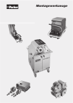
• Para manipular el sujetador de apriete, utilice la herramienta. • Introduzca el sujetador de apriete hasta el tope. • La parte frontal del sujetador de apriete debe estar • Suelte el gatillo. perfectamente alineada con • Tire de la palanca o gatillo y su compartimento. • El sujetador de apriete debe sujételo para ajustar el • Ponga en funcionamiento el proceso. • Pulse la tecla Reset después de cada puesta en funcionamiento. estar colocado perfectamente • La máquina realiza un sujetador de apriete. en el compartimento. • Sin herramienta no es posible poner en marcha el proceso (la tecla RESET parpadea en forma rápida) reconocimiento automático de la herramienta. Se cierra el sujetador de apriete. • Mantenga pulsada la tecla de reinicio (RESET) hasta que se ilumine. • Cuando la tecla de reinicio (RESET) se haya iluminado, significa que la máquina está lista para funcionar. • El extremo de los tubos no • Introduzca el extremo del debe presentar aristas, tubo con la tuerca en la y manténgala pulsada hasta de apriete, puede sacarse el virutas ni restos de suciedad. herramienta abierta hasta que el tubo esté tenso. En tubo. Lubrique la parte interior y que quede perfectamente lugar de pulsar la tecla de exterior del extremo del tubo. ajustado. inicio (Start), se puede utilizar se ilumina y la máquina ya el interruptor de pie. está preparada para el • Utilice el lubricante 1040LUBSS • Empuje el extremo del tubo • Pulse la tecla de inicio (Start) hasta que llegue al tope de la • Empuje el tubo hasta el tope herramienta. de manera que quede bien • No gire el tubo en el sentido contrario de las agujas del reloj. tenso. • Para tubos largos, utilice un puntal o punto de apoyo. • Durante el proceso de trabajo • Una vez abierto el sujetador • La tecla de reinicio (RESET) próximo proceso. • Compruebe regularmente (después de aproximadamente 50 montajes) que las herramientas no tengan no ponga las manos en la suciedad o estén zona de la herramienta desgastadas. • Sin herramienta no es • Limpie las herramientas posible poner en marcha el siempre sin alterar el estado proceso (la tecla RESET en el cual se han parpadea en forma rápida) suministrado. • Limpie el sujetador de apriete con un cepillo de alambres y limpie el sellado de transformación con aire comprimido. • Reemplace las herramientas gastadas. - 170 - 3.7 Control de montaje Tabla 3 • Control de cada empalme Serie • Los montajes defectuosos deben corregirse • La superficie de sellado no • Controle el contorno: la • Compruebe el diámetro del debe estar dañada ni superficie de contacto para el presentar acanaladuras sellado debe formar un collar (tabla 3). • No deben utilizarse los ángulo recto. extremos de tubo defectuosos. Compruebe y limpie las herramientas. 3.8 min max Tubo AD Ø Ø 6L/S 8L/S 10L 12L 15L 18L 22L 28L 35L 42L 10S 12S 16S 20S 25S 30S 38S 8,4 10,8 12,8 14,8 18,5 21,5 26 32 39,5 46,5 13,5 15,5 19,5 24,5 30 35 43 10,3 12,3 14,3 16,3 20,3 24 27,8 33,8 42,5 49,5 15,5 17,5 21,5 27,5 34 39 47 Instalación • El tubo debe entrar sin forzar • Monte el anillo de sellado (DOZ) • Se debe lubricar la rosca de • El tubo debe entrar sin forzar. • Después apriete firmemente • Apriete hasta que el aumento los tornillos de acero inoxidable. de la fuerza de resistencia • EO-NIROMONT es un con 1/6 de giro. • Se recomienda utilizar una sea claramente perceptible extensión de llave a partir de lubricante de alta calidad (sin llegar a la extensión de RAD 20 (tabla C). especial para tornillos de la llave). acero inoxidable. • No seguir escrupulosamente Tabla C Tamaño 18-L 22-L 28-L 35-L 42-L 16-S 20-S 25-S 30-S 38-S Longitud de la llave H (mm) 300 400 500 900 1200 1500 - 171 - este método de montaje va en detrimento de la eficacia y de la durabilidad del empalme.. 3.9 Posibles problemas y su solución Problemas Causas Solución 1. La máquina está en Dirección de rotación (fases) incorrecta funcionamiento, pero en la toma de corriente CEE (→ la no se mueve bomba funciona incorrectamente) 2. El sellado de molde no puede introducirse El pasador no está centrado en la máquina Invertir las fases en el enchufe CEE con un destornillador Centrar el pasador y asegurarlo con un espárrago roscado Utilizar tubos adecuados. Comprobar Tubo AD demasiado grande que los tubos se ajustan a la norma DIN 2391/ISO 3304 Sellado de molde y/o grosor de la pared del tubo incorrectos para el diámetro y el grosor de la pared del tubo 3. El tubo no puede introducirse en el El tubo no se ha desbarbado con sellado de molde esmero El extremo del tubo esta ovalado El tubo no se ha limpiado cuidadosamente El sellado de molde está sucio El diámetro exterior del tubo es demasiado pequeño 4. El tubo resbala Seleccionar el sellado de molde correcto Desbarbar y quitar las virutas Comprobar que el tubo no esté ovalado Limpiarlo y retirar los restos de suciedad Limpiar el sellado de molde Comprobar que el diámetro exterior del tubo se ajuste a la norma DIN 2391/ISO 3304 La superficie del sujetador de apriete Limpiar con un cepillo de alambres / está sucia disolvente La superficie del sujetador de apriete está desgastada La superficie del tubo es inadecuada - 172 - Reemplazar el sujetador de apriete Quitar la capa de color o el óxido Problemas Causas Solución 1. Destornillar la parte frontal de la cabeza del molde (marcar antes la posición). 2. Sacar el sellado de molde con el tubo. 5. El tubo no se puede sacar y está atascado en el sellado de molde El tubo ha resbalado en el sujetador de apriete 3. Destornillar la parte frontal de la cabeza del molde; tirar firmemente hasta la marca. 4.Cambiar el sellado de molde. 5. Limpiar el sujetador de apriete y, si está desgastado, cambiarlo. 6. En el futuro, lubrifique la parte interior y exterior de los tubos 1. Parar la propulsión de la máquina (0) 2. Activar la propulsión de la máquina (I) 3. Pulsar la tecla de reinicio (R) 4. El sujetador de apriete se abre 5. Introducir el sellado de molde con el 6. El tubo no se puede sacar y está atascado en el sellado de molde. A veces no se abre el sujetador de apriete. El sellado de molde se ha soltado del cierre de bayoneta (el tubo se ha girado en sentido contrario a las agujas del reloj) tubo en el cierre de bayoneta y volverlo a retener girándolo en el sentido de las agujas del reloj 6. Pulsar la tecla de inicio (Start) y ejecutar una nueva transformación. 7. Sacar el tubo tras haber abierto el sujetador de apriete. 8. En caso de que el tubo no pueda sacarse, se debe destornillar la cabeza del molde, consultar el problema 5. 7. El extremo del tubo Se ha utilizado un sellado de molde Seleccionar el sellado de molde para un grosor de la pared del tubo correcto para el correspondiente grosor demasiado grande de la pared del tubo Se ha utilizado un sellado de molde Seleccionar el sellado de molde no se ha transformado para otro material correcto para acero/acero inoxidable completamente Empujar el tubo hasta el tope. No se ha empujado el tubo hasta el Desbarbar el extremo del tubo con tope esmero. Comprobar que el tubo no esté ovalado. - 173 - Problemas Causas Solución 8. Demasiada El sellado de molde está sucio Limpiar el sellado de molde El sellado de molde está desgastado, Lubricar la parte interior y exterior del no se ha utilizado lubricante tubo. Cambiar el sellado de molde rugosidad de la superficie de sellado 9. La tecla RESET Temperatura demasiado alta parpadea en forma lenta 10. La tecla RESET parpadea en forma Nivel de aceite demasiado bajo No hay herramienta colocada en la máquina rápida; la tecla Start El sellado de molde se ha soltado del no puede accionarse cierre de bayoneta Dejar que la máquina se enfríe durante 5 minutos Controlar el nivel de aceite y agregar aceite hidráulico en caso necesario Colocar herramienta en la máquina Colocar correctamente el sellado de molde y encajarlo en el cierre de bayoneta girándolo hacia la derecha - 174 - Declaración de conformidad CE según anexo II A de la directiva de maquinaria CE (98/37/CEE) Por la presente, el fabricante Parker Hannifin GmbH Am Metallwerk 9 33659 Bielefeld declara que el siguiente producto Centro de trabajo de transformación EO2 – FORM F3 cumple con todos los requisitos básicos de seguridad y salubridad de la directiva mencionada más arriba – incluyendo las modificaciones a la misma vigentes al momento de la presente declaración. El producto satisface además las siguientes Directivas de la UE: 73/23/CEE Directiva de baja tensión CEE 89/336/CEE Directiva de compatibilidad electromagnética CEE Se observaron las siguientes Normas harmonizadas: EN 12100, Parte 1 y Parte 2 EN 294 EN 982 EN 418 EN 60204, Parte 1 Seguridad de las máquinas, aparatos e instalaciones Distancias de seguridad para impedir que se alcancen zonas peligrosas con los miembros superiores Requisitos de seguridad para sistemas y componentes para transmisiones hidráulicas y neumáticas Seguridad de las máquinas; equipos de paro de emergencia Seguridad de las máquinas; equipo eléctrico de las máquinas. Requisitos generales Cualquier modificación constructiva que cambian los datos técnicos indicados en el manual de instrucciones y el uso según finalidad, es decir que modifiquen profundamente la máquina, invalidarán esta declaración de conformidad! El abajo firmante tiene los poderes necesarios para firmar la declaración en representación del fabricante. Bielefeld, 12.12.2007 _______________________ (Firma/sello) - 175 - - 176 - Formnings-WorkCenter EO2 - FORM F3 1 2 3 Säkerhetsanvisningar ......................................................................................178 1.1 Användning ................................................................................................................. 178 1.2 Generella säkerhetsanvisningar .................................................................................. 178 1.3 Säkerhetsanvisningar för maskinens olika faser .......................................................... 179 1.4 Säkerhetsanvisningar för montering av EO2-FORM .................................................... 180 EO-2 FORM F3 maskin .....................................................................................182 2.1 Beskrivning av manöverorgan ..................................................................................... 182 2.2 Tekniska data .............................................................................................................. 184 EO-2 FORM F3 monteringsanvisning .........................................................185 3.1 Monteringsförlopp........................................................................................................ 185 3.2 Kombination av material .............................................................................................. 186 3.3 Förberedelse av rör ..................................................................................................... 186 3.4 Tabell förberedelse av rör – serie L ............................................................................. 187 3.5 Tabell förberedelse av rör – serie S............................................................................. 188 3.6 Rörformning med EO2-FORM F3 ................................................................................ 189 3.7 Monteringskontroll ....................................................................................................... 191 3.8 Installation ................................................................................................................... 191 3.9 Möjliga störningar och åtgärder ................................................................................... 192 EU Konformitetsförklaring ............................................................................................195 - 177 - 1 Säkerhetsanvisningar 1.1 Användning Maskinen EO2 – FORM F3 lämpar sig enbart för formning av hydraulrör för EO-2 högtryckskopplingar enligt DIN EN ISO 8434-1 / DIN 2353. All angiven arbetsdata och all övrig teknisk specifikation avseende maskinen måste följas utan undantag. Används maskinen på annat sätt eller utöver det angivna anses detta som ej avsedd användning. Tillverkaren ansvarar ej för uppkommen skada som uppstår på grund av detta. OBS! i 1.2 Vid avsedd användning ingår även att alla säkerhetsföreskrifter i driftsanvisningen samt inspektions- och skötselarbetena beaktas och följs. Generella säkerhetsanvisningar Alla användare måste alltid, förutom att beakta varningarna i driftsanvisningen, noggrant följa dessa bestämmelser. • Teknikens ståndpunkt: Maskinen är byggd med dagens teknik och är driftsäker, men om maskinen används på fel sätt kan den orsaka fara. • Driftbestämmelser: I driftbestämmelserna ingår uppgifterna om användning och ändamål, varningsskyltarna på maskinen samt instruktionerna i driftsanvisningen. • Användarutbildning: Maskinen får enbart installeras, drivas och skötas av informerade och auktoriserade personer. Operatören säkerställer att personalen är underrättad om farorna vid användningen av maskinen. • Kompetensavgränsning: Operatören fastställer behörigheterna vid installation, drift och underhåll och ser till att detta följs. • Olämpligt beteende: Alla arbetssätt som negativt påverkar säkerheten för personer, saker, förmögenheter eller miljö bör underlåtas. - 178 - • Tillträde av obehöriga: Operatören måste säkerställa att enbart auktoriserade personer använder maskinen. • Konstruktiva ändringar: Egenmäktiga ombyggnader och förändringar är ej tillåtna, då de påverkar maskinens säkerhet. • Skyldighet till underhåll: Operatören förpliktar sig att enbart använda maskinen i felfritt skick. • Övriga säkerhetsföreskrifter: I varje fall gäller de branschspecifika och nationella arbetssäkerhets- och olycksförebyggande föreskrifterna. 1.3 Säkerhetsanvisningar för maskinens olika faser Förutom bestämmelserna om maskinens använding och de generella säkerhetsbestämmelserna, observera följande säkerhetsbestämmelser som gäller i maskinens olika faser. 1.3.1 Maskinens drift • Personal för manövrering: Maskinen får enbart hanteras av en person som känner till och kan arbeta enligt driftsanvisningen. Om hjälp behövs vid arbeten med stora arbetsstycken, måste den hjälpande personen hålla i arbetsstycket där det är riskfritt. • Säkerhetsanordningar: Maskinen får enbart användas när maskinens alla säkerhetsanordningar är monterade och fungerar. 1.3.2 Skötsel och underhåll • Underhåll: Skötsel- och underhållsarbeten får enbart genomföras av auktoriserade personer. Komponenter som säkerställer maskinens säkerhet måste ersättas fackmässigt enligt vår dokumentation och med likadana delar. • Frånskiljning: Innan ingrepp i maskinen, styrningen eller i andra komponenter, säkerställ alltid att strömmen och trycket är frånkopplade. - 179 - 1.4 Säkerhetsanvisningar för montering av EO2-FORM En rätt monterad EO-förskruvning håller tätt tills röret spricker. Erfarenheten har visat att funktionsstörningar, åtdragning och läckage kan undvikas genom att iaktta följande säkerhetsanvisningar. Kontrollera dina monteringsvanor. 1.4.1 Allmänna säkerhetsanvisningar • EO-förskruvningar är utformade enbart för att bygga kopplingar för rör som används till flytande ämnen. • Följ de rekommendationer som gäller för rören. Avvikande material eller toleranser leder till felaktig montering. • Röranslutning och skruvkopplingskropp hör ihop när de en gång monterats. • Det är livsfarligt att dra åt och lufta förskruvningar som står under tryck. • Fäst aldrig rör på varandra utan på speciella fixpunkter som är lämpade till detta. Plåtklamrar, kabelbindare och fästen är inte lämpliga. Rören är inga hållare till inbyggda delar som t ex filter, fläktar eller ventilblock. • Vid demontering / transport och återuppbyggnad av invändiga rör skall man försäkra sig om att ingen smuts har trängt in i systemet och att anslutningsdelar (gängor, tätningsytor) inte skadats, inga tätningar försvunnit och inga ledningar böjts eller tryckts ihop. Vi rekommenderar att lämpliga skyddskåpor används. • Kontrollera att demonterade förskruvningar håller måttet och är oskadda och ersätt dem vid behov. • Använd inga manuella slipverktyg eller röravskärare. • Föroreningar och spån kan leda till störningar i systemet och läckor på kopplingar. • De angivna driftförhållandena (t ex tryck, temperatur, mediatolerans) skall alltid vara desamma. • Strömningshastigheter på > 8 m/s skall undvikas eftersom påverkar de böjda rörledningarna med starka krafter och därför kan leda till rörledningsbortfall. - 180 - • Följ de tillämpliga riktlinjerna (t ex BG, TÜV, DIN). • Endast svetsförskruvningar är tillverkade av material som går att svetsa. Andra förskruvningar lämpar sig inte till svetsning. • EO-Niromont är ett högeffektivt smörjmedel för förskruvningar av ädelstål. Används andra smörjmedel leder det i regel till att det krävs mera kraft för monteringen. • De verktyg och apparater som rekommenderas av EO garanterar en säker monteringsprocess. Används verktyg/apparater från andra tillverkare måste deras lämplighet till EO-förskruvningar kontrolleras • Förskruvningar är inget fyllnadsmaterial. • Rörledningar måste passas in utan att spännas före montering. Kopplingsmuttern måste fortfarande gå lätt att skruva längs hela gängan. I annat fall kan det leda till läckage – eller vid ökat antal vibrationer – brott på rören. • Vibrationer måste fångas upp av rörfästen som utformats för detta ändamål. Vibrerande system som är oberoende av varandra måste kopplas ifrån med slangar. Görs inte det leder det till brott på rören. 1.4.2 Säkerhetsanvisningar för montering En ofullständig montering minskar tryck- och vibrationståligheten och därmed förskruvningens livslängd. Följden blir läckage och i värsta fall rörledningsbortfall genom att röret klipps av eller bryts. Varje gång en förbindning har lossats skall kopplingsmuttern skruvas fast lika hårt som vid den första monteringen. Skruvas den för löst kan resultatet bli läckage och minskad vibrationstålighet. Skruvas den för hårt minskas möjligheten att upprepa monteringen och i värsta fall kan det leda till att komponenter förstörs. - 181 - 2 EO-2 FORM F3 maskin 2.1 Beskrivning av manöverorgan 3 7 6 5 4 8 1 2 - 182 - Pos. Komponent Märkning 1 Totalstyckräknare 2 Huvudströmbrytare 3 Styckräknare 4 Tryckknapp OFF 5 Tryckknapp ON Funktion 1 = ON 0 = OFF Vrid huvudströmbrytare till önskat läge Tryck på knappen för att återställa styckräknaren Tryck på knapp (OFF) för att koppla från maskinen Tryck på knappen (ON) för att slå på maskinen. Knappen (ON) lyser vid påslagen maskin. Tryck på knappen (RESET), för att starta den automatiska verktygsigenkänningen. Håll knappen (RESET) tryckt tills den tänds. Tänd (RESET) knapp visar maskinens startberedskap. Knappen (RESET) blinkar långsamt, när 6 RESET Tryckknapp • hydraulikens fyllningsnivå är för låg! • hydraulikens temperatur är för hög! (återställning) Knappen (RESET) blinkar snabbt, när • inget verktyg är isatt i maskinen! Tryck på knappen (RESET), för att åter slå på hydrauliken efter inaktivitet av maskinen ( 5 minuter )! 7 Tryckknapp START 8 NÖDSTOPP NÖDSTOPP Tryck på knappen, för att utlösa arbetsförloppet. Håll knappen tryckt, tills röret är spänt. Tryck på knappen NÖDSTOPP i nödsituationer! - 183 - 2.2 Tekniska data Formningsprestanda Stålrör ST 37.4: 6 x 1 mm till 38 x 7 mm / 42 x 4 mm Ädelstålrör 1.4571: 6 x 1 mm till 38 x 5 mm / 42 x 3 mm Intervalltid: 15 till 20 sekunder Mått Bredd: 600 mm Djup: 660 mm Höjd: 1150 mm Vikt: ca. 300 kg Hydraulik Arbetstryck: 800 bar Nominellt tryck: 250 bar Flödeseffekt: Inkopplingsvaraktighet: 3,3 l/min 100% Oljetanksvolym: 13 Liter Oljetyp: HLP 46 Anslutningsvärden Framdrivningseffekt för elektrisk motor: 3,0 kW Total anslutningseffekt: 3,0 kW Nominell spänning: 400 V AC 3 N / PE / 50 Hz Kabeltvärsnitt för inkommande ledning: 5 x 2,5 mm² Nominell strömstyrka för huvudsäkring: max. 25 A - 184 - 3 EO-2 FORM F3 monteringsanvisning 3.1 Monteringsförlopp Monteringen av EO2-FORM-rör genomförs enligt detta schema: Kombination av material • Välj lämplig skruvkoppling enligt användningsvillkoren och rörets material Förberedelse av rör • Kapa noggrant till rätt längd • Anpassa rören exakt Rörformning Med EO2-FORM F3 • Formanpassad förbindelse • Tillförlitlig process Monteringskontroll • Kontroll av varje förbindelse • Felaktiga monteringar måste skrotas Installation • Slutmontering enligt monteringsanvisningarna • Montera spänningsfritt • Fäst stadiga fixpunkter - 185 - 3.2 Kombination av material Tabell 1 • Välj lämpligt material • Rörspecifikation se katalog Rörets Kopplingens Tätningens material material material Stål / NBR NEW GENERATION 4013-1/DE Stål Stål eller Stål / FPM Rostfritt stål / Rostfritt stål Rostfritt stål NBR eller Rostfritt stål / NBR Rostfritt 3.3 Förberedelse av rör stål Stål / NBR Stål eller Stål / FPM • Kapa noggrant till rätt längd • Montera spänningsfritt • Fäst på stadiga fixpunkter • Observera längdtilläggen (tabell). • Observera minimilängden L2 för raka rördelar (tabell). • Håll minimiavståndet vid rörböj (tabell). • Såga av röret i rät vinkel. • Max avvikelse ± 1º. • Använd ej rörkapare. • EO-såganordning (AV). • Grada av röret in- och utvändigt. • Grader på inner- och ytterdiameter, spån, smuts • Max fasad kant: 0,3 x 45º. och lackeringar hindrar vid • Rekommendation: införandet av röränden. Handavgradare modell 226. • Smuts kan innebära att verktygen slits eller förstörs. - 186 - 3.4 Tabell förberedelse av rör – serie L • Längdtillägg • Minimilängd för raka • Rak längd vid rörböj • Minimiavstånd vid u-böj rör Rörets YD S L L L1 L1 serie Väggtjocklek Stål Rostfritt stål Stål Rostfritt stål 6L 1 1,5 1 1,5 12 1 1,5 2 1 1,5 2 1,5 2 2,5 1,5 2 2,5 3 1,5 2 2,5 3 1,5 2 2,5 3 2 2,5 3 4 6 6 5,5 5,5 5 5,5 5 5 4,5 5 5 5,5 5,5 5,5 5,5 5,5 5,5 5,5 6 6 6,5 6 6 5,5 5,5 13 13 12,5 12,5 8 8 8 13 13 12,5 12,5 12 12,5 12 12 11,5 12 12 12,5 12,5 12,5 13 13 13 13 13,5 13,5 14 5,5 6,5 7 6,5 7,5 8 7 7,5 8,5 2 3 4 7,5 9 9 8L 10L 12L 15L 18L 22L 28L 35L 42L 5,5 6 6 5 6 6 7 6,5 L2 L2 90 63 92 65 95 68 12,5 13 13 12 13 13 14 13,5 95 70 102 75 14,5 14,5 110 80 15,5 15,5 15,5 120 90 13 14 14,5 14 15 15,5 140 98 8,5 9,5 10,5 17,5 18 19 19 20 21 170 115 9 10,5 18,5 20 20 20 21,5 190 125 7 7 - 187 - 3.5 Tabell förberedelse av rör – serie S • Längdtillägg • Minimilängd för raka • Rak längd vid rörböj • Minimiavstånd vid u-böj rör Rörets YD S L L L1 L1 serie Väggtjocklek Stål Rostfritt stål Stål Rostfritt stål 1 1,5 2 1 1,5 2 1,5 2 1,5 2 1,5 2 2,5 3 2 2,5 3 3,5 2 2,5 3 4 3 4 5 2,5 3 3,5 4 5 6 7 6 6 5,5 5,5 5,5 5 5 5 5 5 5 5 5 5 7 7 7 7 8,5 8,5 8,5 8,5 8,5 9,5 8,5 6 6 13 13 12,5 12,5 12,5 12 12,5 12,5 12,5 12,5 13,5 13,5 13,5 13,5 17,5 17,5 17,5 17,5 20,5 20,5 20,5 20,5 22 23 22 6S 8S 10S 12S 16S 20S 25S 30S 38S 11 11 10 11 11,5 11,5 5,5 5,5 6 6 6,5 6,5 6,5 6 6 6 8,5 8,5 8,5 10,5 10,5 10,5 10,5 11 11 11 12 13 - 188 - 27 27 26 27 27,5 27,5 L2 L2 13 13 92 65 12,5 12,5 95 68 13,5 13,5 14 14 15,5 15 14,5 14,5 19 19 19 100 70 100 72 110 80 135 98 155 112 165 122 190 135 22,5 22,5 22,5 24 24,5 27 27 28 29 3.6 Rörformning med EO2-FORM F3 • Formanpassad förbindelse • Tillförlitlig process • Byte av verktyg enbart när drivenheten är avstängd (knapp OFF). • Följ säkerhetsanvisningarna. • Placera stämpeln i maskinen med hjälp av magnethållaren. • Vrid medsols tills • Öppna dörrarna till • Använd lämplig stämpel med verktygsmagasinet. • Hanteringsverktygen ligger i • Kontrollera stämpeln med avseende på rörets material, avseende på nedsmutsning, ytterdiameter och slitage och skador. väggtjocklek. magasinets övre del. • Vik bort magnethållaren för att placera stämpeln i magasinet. • Använd lämpliga med avseende på på rörets ytterdiameter. nedsmutsning, slitage och • Använd spännbackar enbart bajonettlåset låser. för ett och samma material för att undvika kontaktkorrosion vid rör av rostfritt stål. - 189 - • Kontrollera spännbackarna spännbackar med avseende skador. • Använd hållaren vid hantering • För in spännbackarna så av spännbackarna. • Drag och håll i spaken för att långt det går. • Spännbackarnas framkant måste ligga kant i kant med • Släpp spaken. hållaren. • Inget mellanrum får finnas greppa spännbackarna. • Slå på drivenheten. • Tryck alltid reset-knappen (RESET) efter påslagning. • Maskinen genomför mellan spännbackarna och automatisk detektering av hållaren. verktyg. Då stängs • Utan verktyg är det inte möjligt att utlösa arbetsgången (RESET – Knappen blinkar snabbt) spännbackarna. • Håll reset-knappen (RESET) nedtryckt tills den börjar lysa. • När reset-knappen (RESET) lyser är maskinen startklar. • Röränden måste vara fri från grader, spån och smuts. Smörj röränden in- och utvändigt. • Använd 1040LUBSS som smörjmedel. • För in röränden med ditsatt • Tryck start-knappen (START) • Röret kan tas ut efter det att mutter så långt det går i det och håll den nedtryckt tills öppna verktyget. röret är fastspänt. I stället för • Tryck röränden hårt mot verktygets stoppanordning. • Vrid inte röret motsols. start-knappen (START) kan fotströmbrytaren avändas. • Tryck röret hårt mot • Reset-knappen (RESET) börjar lysa och maskinen är klar för nästa formning. • Kontrollera verktyget stoppanordningen tills det regelbundet (efter ca 50 sitter spänt. monteringar) med avseende • Använd stöd vid långa rör. • Håll dig på avstånd från verktyget under arbetsförloppet. • Utan verktyg är det inte möjligt att utlösa arbetsgången (RESET – Knappen blinkar snabbt) - 190 - spännbackarna har öppnats. på nedsmutsning och slitage. • Ta bort verktyget innan rengöring. • Rengör spännbackarna med en stålborste och blås ur stämpeln med tryckluft. • Byt slitna verktyg. 3.7 Monteringskontroll Tabell 3 • Kontroll av varje förbindelse • Felaktiga monteringar måste korrigeras • Tätningsytan måste vara fri från räfflor och skador. • Kontrollera konturen: • Kontrollera kragens diameter Kontaktytan för tätning måste (tabell 3). • Felaktiga rörändar får inte vara formad i rät vinkel. användas. Rengör och kontrollera verktygen. 3.8 Serie min max rörets YD 6L/S 8L/S 10L 12L 15L 18L 22L 28L 35L 42L 10S 12S 16S 20S 25S 30S 38S Ø 8,4 10,8 12,8 14,8 18,5 21,5 26 32 39,5 46,5 13,5 15,5 19,5 24,5 30 35 43 Ø 10,3 12,3 14,3 16,3 20,3 24 27,7 33,7 42,5 49,5 15,5 17,5 21,5 27,5 34 39 47 Installation • Röret måste passa utan att spänning i materialet uppstår • Montera tätningsringen (DOZ). • Smörj gängorna vid • Röret måste passa utan att • Dra därefter åt med 1/6 varv. spänning i materialet uppstår. • Använd rekommenderad användning av skruvkopplingar i rostfritt stål. • EO-NIROMONT är ett • Dra åt tills en tydlig motståndsökning märks speciellt högpresterande nyckelförlängning från och med RYD 20 (tabell C). (förläng inte skruvnyckeln). smörjmedel för skruvkopplingar i rostfritt stål. • Avvikande monteringssätt Tabell C Mått 18-L 22-L 28-L 35-L 42-L 16-S 20-S 25-S 30-S 38-S Nyckelns längd H (mm) 300 400 500 900 1200 1500 - 191 - påverkar kopplingens prestanda och livslängd. 3.9 Möjliga störningar och åtgärder Störningar 1. Drivenheten går, men ingen rörelse är möjlig. 2. Stämpeln kan inte sättas in i maskinen. Orsaker Åtgärder Fasföljden i CEE-eluttaget är felaktig (→ Vänd på faserna i CEE-kontakten pumpen går åt fel håll). med hjälp av en skruvmejsel. Styrstiftet är inte centrerat. Centrera styrstiftet och säkra med stiftskruv. Använd rätt rörtoleranser. Rörets ytterdiameter är för stor. Kontrollera rörtoleransen enligt DIN 2391/ISO 3304. Stämpeln och/eller rörets väggtjocklek är 3. Röret kan inte föras in i stämpeln. felaktiga. Välj rätt stämpel med avseende på rörets diameter och väggtjocklek. Röret är inte tillräckligt noga avgradat. Grada av och ta bort spånen. Röränden är oval. Kontrollera att röret inte är ovalt. Röret är inte tillräckligt noga rengjort. Rengör röret och ta bort rester från avgradningen. Rengör stämpeln. Stämpeln är smutsig. Kontrollera toleransen för rörets Rörets ytterdiameter är för liten. ytterdiameter enligt DIN 2391/ISO 3304. Spännbackarnas yta är smutsig. 4. Röret glider. Rengör med stålborste/lösningsmedel. Spännbackarnas yta är sliten. Byt spännbackarna. Rörets yta är ej lämplig. Ta bort färg, rost osv. - 192 - Störningar Orsaker Åtgärder 1. Skruva loss framdelen av formens huvud (märk ut positionen innan). 2. Ta bort stämpeln samt röret. 3. Skruva dit framdelen av 5. Röret kan inte tas ut och sitter fast i Röret sitter i spännbackarna. stämpeln. formens huvud och dra åt tills märket är nått. 4. Byt stämpeln. 5. Rengör spännbackarna. Byt dem om de är slitna. 6. Smörj rören in- och utvändigt i framtiden. 1. Stäng av drivenheten (0). 2. Slå på drivenheten (I). 3. Tryck reset-knappen (R). 4. Spännbackarna öppnar sig. 5. Sätt stämpeln samt röret i 6. Röret kan inte tas ut och sitter fast i stämpeln. Möjligtvis öppnar inte bajonettlåset och lås genom att Stämpeln har lossnat ur bajonettlåset (röret vrida medsols. har vridits motsols i stämpeln). 6. Tryck start-knappen (START) och genomför en ny formning. spännbackarna. 7. Ta ut röret efter det att spännbackarna har öppnats. 8. Om röret inte kan tas ut måste formens huvud skruvas loss, se rad 5. 7. Röränden är inte Stämpel för en större väggtjocklek har Välj rätt stämpel med avseende använts. på rörets väggtjocklek. Stämpel för ett annat material har använts. fullständigt formad. Välj rätt stämpel för stål / rostfritt stål. Tryck röret mot stoppanordningen. Röret har inte tryckts mot stoppanordningen. Grada av röränden noggrant. Kontrollera att röret inte är ovalt. - 193 - Störningar 8. Tätningsytan är för ojämn. 9. RESET – Knappen blinkar långsamt 10. RESET – Orsaker Åtgärder Stämpeln är smutsig. Rengör stämpeln. Stämpeln är sliten, inget smörjmedel har Smörj rören in- och utvändigt. Byt använts. stämpeln. Temperaturen är för hög. Låt maskinen svalna i ca 5 min. Kontrollera eventuellt oljenivå Fyll Oljenivå för låg på hydraulolja inget verktyg är isatt i maskinen Knappen blinkar snabbt; Start går inte Sätt i verktyg i maskinen Sätt i formstämpelriktning och lås Formstämpeln har lossnat ur bajonettlåset att aktivera genom högervridning i bajonettlåset - 194 - EU Konformitetsförklaring Som avses i EG-Maskinriktlinje 98/37/EG, Bilaga II A Härmed deklarerar tillverkaren, Parker Hannifin GmbH Am Metallwerk 9 33659 Bielefeld att följande produkt Formnings- Work Center EO2 – FORM F3 överensstämmer med alla grundläggande säkerhets- och hälsokrav i ovannämnda riktlinje – inklusive de vid tidpunkten av denna deklaration giltiga ändringar. Produkten är överensstämmande med följande ytterligare EU-riktlinjer: 73/23/CEE EG-Lågspänningsriktlinje 89/336/CEE EG-Riktlinje elektromagnetisk kompatibilitet Följande harmoniserande normer har uppfyllts: EN 12100, del 1 och del 2 EN 294 EN 982 EN 418 EN 60204, del 1 Säkerhet av maskiner, apparater och anläggningar Säkerhetsavstånd mot att nå farliga ställen med övre lemmar Säkerhet på vätsketekniska anläggningar och deras komponenter; hydraulik Säkerhet av maskiner; NÖDSTOPPsanordningar Säkerhet av maskiner; elektriska utrustningar på maskiner, allmänna krav Ändringar i konstruktionen som påverkar de tekniska data som anges i driftsinstruktionen och den föreskrivna användningen och alltså väsentligt förändrar maskinen gör denna konformitetsförklaring ogiltig! Undertecknad äger fullmakt att underteckna förklaringen för tillverkaren. Bielefeld, 12.12.2007 _______________________ (Underskrift/Stämpel) - 195 - Appendix / Anhang Hydraulic circuit diagram / Hydraulikschaltplan - 196 - Elektric circuit diagram / Elektroschaltplan - 197 - 1 2 3 4 5 6 8 Schutzvermerk "DIN 34" Parker W ei tergabe s owi e V erv i el- Anlage: E O 2 - F o r m 4 7 fäl ti gung di es er Unterlage, F3 V erwertung und Mi ttei lung 4 ihres Inhalts nicht gestattet Maschinennr.: 4 0 1 1 0 / 7 0 - 9 0 s o w e i t n i c h t a u s d r ü c k l i c h z ugestanden. Zuwiderhandlungen v e r p f l i c hten z u S c hadens - 3 Phase L1, L2, L3 Neutralleiter Schutzleiter PE S t e u e r s p a n nung S t e u e r s p a n nung S t e u e r s p a n nung S t e u e r s p a n nung S t e u e r s p a n nung S t e u e r s p a n nung 230 V AC 50 Hz Phase 230 V AC 50 Hz Neutral 24 V AC 50 Hz Phase 24 V AC 50 Hz Neutral 24 V DC + 24 V DC - e r s a t z . A l l e R e c h t e für den schwarz blau gelb-grün rot rot, rot-schwarz braun braun, braun-schwarz blau blau, blau-schwarz F a l l d e r P a t e n t e r tei l ung oder Gebrauchsmuster Eintragung vorbehalten. 3 Querschnitt min. Haupts trom 1,5 qmm Steuerstrom 0.75 qmm Kabeleinführung Links unten 2 Schaltschrank: Rittal Planübersicht D : Blatt A : Blatt S : Blatt Klemmleistenübersicht :Deckblatt :Ansichten Schaltschrank :Stromlaufpläne Klemmleistenbezeichnung X1 2 Lackierung: RAL 7035 xx Klemmennummer K l emmleiste X0 : Einspeisung X1 : Hauptstrom X2 : Ein-/Ausgänge X3 : Ventile X4 : Ini ti atoren XP : Potentiale XS1 : 1 G e r ä t e k e n n z e i chnung 3 K 2 Z ä h l -Nr. Funktionsbez. Blattbez. 1 Fussschalter Datum Kommission: Bearb. Deckblatt Blatt-Nr. Gepr. Zust. Änderung Datum 1 von Name Norm 2 D 3 4 5 6 7 Blatt 8 1 2 3 4 5 Pos. 7 4 6 5 3 ! 2 4 " 1 35 115 Maschinenschrank Rittal AE 1038.600 85 55 35 3 45 " %& " 9 9 1 %& 9 # '% $ Linke Seite 2 160 9 9 ! 9 120 9 8 80 9 1 2 3 4 5 6 7 8 9 10 11 12 13 14 15 16 17 18 19 20 21 22 23 24 25 26 27 28 6 MKG 8 7 Text 2Q1 Hauptschalter 3S7 Anlage Aus 3S7.1/3H6 Anlage Ein 2S6 N o t -A us 5S7.1/5H6 Grundstellung 5S6 Automatik start 5H8 Stückzähler Bedienpult 5H7 Stückzähler Schaltschrank 4 Loch PG16 (22,5mm) 3 2 1 1 Datum Kommission: Bearb. Ansichten Blatt-Nr. Gepr. Zust. Änderung Datum 1 von Name Norm 2 A 3 4 5 6 7 Blatt 8 1 2 3 4 5 6 8 7 < < < 4 4 - = , , - ! , ? !- ? - 2 = 2 2 3 - 3 - N o t -A us - 8 24V/5A ! ? ? 2 2 9< ? ! < + 01 < "( <$ ? 2 ? <$ <$ < < ? ? ") * ,- ./ 20 #"%& ) /) * " ) " 3 4 ) 5)" ) * " # " 6# " "%&) / * 5) ) * 7 %& %& 01 20 8 #"%& - 9 3 " ) * ? ) " 2 # ) * 7 ) 1" : %&) * ; " & 4 " N o t -A us Kette - - - > - - Kommission: Bearb. Einspeisung Lüfter oben S von Name Norm 2 1 Blatt-Nr. Gepr. 1 > > L ü fter unten 1 Datum ? " > Zust. Änderung Datum 2 3 4 5 6 7 Blatt 8 1 2 3 4 < 5 6 8 7 <$ <$ < ? < 4 4 ! - - ! ! - ? - ! - = , ,- , , Anlage Aus - - = , - 3 3 - !- ? - ! Anlage Ein = - ? ? ? B 2 > .@ .@ 2 A > ! ? ) ) % 2 - ./ A ,- - B 2 , 1 . ? < Einstellung Function: 81 A - - - - - '& % 2 - ./ A , 1 Datum Kommission: Bearb. Hydraulik von Name Norm 2 S Blatt-Nr. Gepr. Zust. Änderung Datum 2 ! ? D ! C > > !- optional: 1 - ! = 3 4 5 6 7 Blatt 8 1 2 3 4 5 6 8 7 <$ < - 4 <$ 4 - 5 # )* )(( F B - F C - - A / )* ) * A / )* ) * .@ ) ) " 9 ) " ) * )" 7 ' " D ! 8 ( ) ! - C - - C - - >2 B 7 - >2 0 - >2 G'% " - - >2 0 )% - <> 9 ) C ( ( * *H * 2 0F ; A )"/)* A - * # 0F B 7 > 3 2 )% " ) * " ) * '% /H& .@ - > F F )"* # )"*H * - 2 0 * <$ > 2 2 > > *H * 0F )"*H * 0F F B F <$ <$ > <$ > <$ 3 > <$ > - 2 ) >2 2 "( > F 7 =) * ) * )7 0 % # %& E *# )* )( ( ( G'% " E 1 1 Datum Kommission: SPS Bearb. Blatt-Nr. Gepr. Zust. Änderung Datum 1 von Name Norm 2 S 3 4 5 6 7 Blatt 8 1 2 3 4 5 6 8 7 <$ < 4 4 !- ? - - - ? <$ ? < - <$ ? ? < - ? - ? - C ? ? ? ? ? )" 7 3 .@ ) A / )* 3 1 ) * 5@ 4 A 3 / )* )"" ) * 5@ ) " 9 ) " ) * 3 4 0 * * * 0 * * * 0 * * * 0 * * * 0 * * * 0 * * * 0 * )"* * 0 * )"* * 0 * )"* * 0 * )"* * 0 * )"* * 0 * )"* * >2 B 7 ; >2 0 )"/)* >2 G'% " - >2 0 )% 2 "( - - - - - " ) * <> 9 ) " ) * - C '% /H& - - 2 - - - 2 ? ? -! -! -! -. -!- ? -. -. ? < - %& '% /H& "%& '% /H& () 1 1 Datum Kommission: Bearb. Ein-/Ausgänge Blatt-Nr. - Gepr. Zust. Änderung Datum 1 von Name Norm 2 S 3 4 5 6 7 Blatt 8 1 - <$ - < 2 ? 4 <$ ? 3 ? < <$ 4 ? 5 6 8 7 4 < ) ? ? C ' 3 " D 0 * ! * 0 * )"* .@ 8 * ( ) 0 * * 0 * * * )"* >2 2 ) 1 ! : # - # : "( - - I ) 3 * - 1 ) I A C B 7 )% 2 2 * ! - * * ! < - 1 1 Datum Kommission: Bearb. Ein-/Ausgänge Blatt-Nr. Gepr. Zust. Änderung Datum 1 von Name Norm 2 S 3 4 5 6 7 Blatt 8 1 2 3 4 5 6 8 7 <$ <$ 4 4 -! -! - - ! -! ! - ! -!- - 3 3 ? 2 J ? < ? $ J ? < ? ? $ J ? < ? ? $ ? J? < $ J ? < ? ? ? $ J ? < ? $ 2 < ? Dornauszug Umformen vor S i t z v enti l Rückstellen Druckentlastung Vorspannen Vorspannen 1 1 2 ) * ) * /; ) * ) * Datum Kommission: Bearb. Ventile Blatt-Nr. Gepr. Zust. Änderung Datum 1 von Name Norm 2 S 3 4 5 6 7 Blatt 8 1 2 3 4 5 6 8 7 4 4 3 3 2 2 1 1 Datum Kommission: Bearb. Ventile Blatt-Nr. Gepr. Zust. Änderung Datum 1 von Name Norm 2 S 3 4 5 6 7 Blatt 8 " 40110par ! " " ( " #$%&'"( ) ' " . " 5 ) " 5 # " 67 8 . , & " 67 8 :; 0 " +,- '"(+ % '(( " /*" 01(.2 % ''" &! *( ( $ + 3 ) ) *" * * . " % #$%&'(( " /*" * * . ) % #$%&''" &! *( * * . # % $%)"# '**) $) + %.4 ) . $%)"# '**) $) + %.4 ) ) # # -, '" . -, '"9.' "(9#*9"9"9(9*" (* # & '%# " 68 7 ' # 4 " "* " % <67 38 68 )%& " "" " % <67 38 =<67 "( " "' " > 68< ' ? % "%C.7D 5> 4 "* A(.2 +B '!. ". " > 68< ' ? % (%?"@C.7D 5> 4 "* A(.2 +B E F 5"" '!) ") " "# " "& " 7 "% (.2 +9( (4 ## #' . )!( ,8 1 "0 " 7 "% (.2 +9( (4 ## #' . )!' ,8 1 "4 " = "D (.2 +9# H A 7 B (4 ## "& " )!. ,8 1 (* " = "D (.2 +9# H A 7 B (4 ## "& " )!) ,8 1 (" " 7 "% (.2 +9( (4 ## #' . #!( ,8 1 (( " 7 "% (.2 +9( (4 ## #' . #!' ,8 1 (' " 1 >< ."0. F ( & , (. " 1 >< ."0. F ( 0 , () " 68 (# " 68 68 *C. *C#' (& " 68 68 #C' "* (0 " 68 68 *C" *C"# (4 " '* " '" " > '( " , '' " / '. " > ') " : '# ) - 68 68< <67 (.2 + '%?"@ ? ) # /)(' *'* '+ /)(' *"* ' 5> '" 9"" "/% "%@ %68 5>$ ? / 5> 68< : (.2 + (.2 + $ 9 -% : C' 5"" ? 5"" C "@ 67 C 67 C "% 68J C "%C K 68 K +B 67 C C "%C K=K * *C#' * "* ? ,! * *C"# ? ,29 5"" 5"" 9 !*" (( = F*9 (( F"9 , %9 F9 $ + (.9) * (.29) ) (( ". *# (**& G *C.' (I. #C) 'I" *C"( 'I( (%) 9 !*" '%& 9 !"*9 >$ D '%& " 9 !"*9 F , % F"* )%# )%& 9 !"*9 >$ D9 F > F# %68 )%& " ('*29*C&) '**.*"# L -:) ! G67 (I" ,! (( 52 '!& /% "@9"% " 7 4 *" A(.2 ,! (( 68 68 ? 52 ) 0 '!# ," ()9$ 9%2 () C)C)7D C"@ 67 68 5> + '%?"@ ) & (!# $:=. #4 > 6 transfluid Maschinenbau GmbH Hünegräben 20 57392 Schmallenberg Kommission: % #.( $ ( / Maschinennr.: .*""* 9 &* 4* /' (:. $ F* ,8 1 Kunde: , 7 , *&9*# **& " ( ( 40110par ! '& 0 '0 ". '4 # .* . ." ' % 68 .( . - .' ( % .. " F% .) " % .# " 2 67 > ! (*** ,$( >$ (. " &M( 68 .& " 2 67 > ! (*** ,$( >$ (. " &M' 68 .0 " 2 67 > ! (*** ,$( >$ (. " &M. 68 .4 " 2 67 > ! (*** ,$( >$ (. " &M) 68 )* " 2 67 > ! (*** ,$( >$ (. " &M# 68 )" " 2 67 > ! (*** ,$( >$ (. " &M& 68 - 7 ) 67 ! 67 7 7 67 '**.*"# F" ,8 1 (&&.*"& F( ,8 1 (&"&*"# F' ,8 1 (&")4## F. ,8 1 F/ ,8 1 F, ,8 1 L -!!) 7 67 5 7 L -:) ) ! "C) 7 5! "C) -! ) ) $%5 >$ '* *. "( # (. ' '**.*"# L -:) . ; ?,$ F%" F%" 67 '1"# ? ,$ ? (1%68 7 ". *# (**& $ '?,$ "4'**"* ")(* ?*4'.**' (#*"9(&*"9*'*" transfluid Maschinenbau GmbH Hünegräben 20 57392 Schmallenberg Kommission: % #.( $ ( / Maschinennr.: .*""* 9 &* 4* 'F%( /' Kunde: , 7 , *&9*# **& ( (