1
ENGLISH
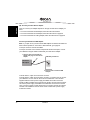
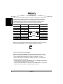
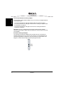
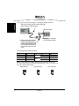
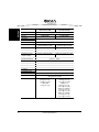
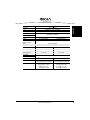
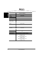
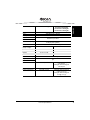
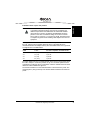
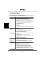
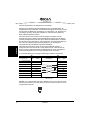
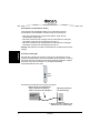
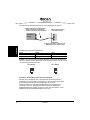
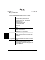
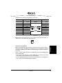
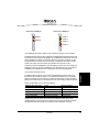
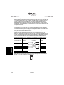
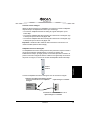
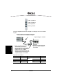
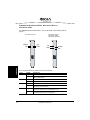
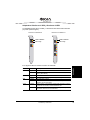
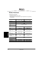
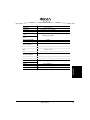
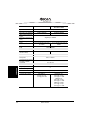
When using two Diva Server adapters in back-to-back operation, configure one
adapter as an NT and the other one as terminal equipment (TE). Connect the
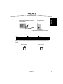
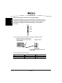
adapters using a crossover cable. The cable wiring must correspond to the
diagram below and the cable must have the required termination resistors.
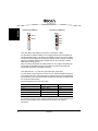
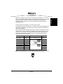
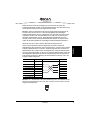
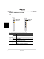
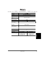
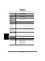
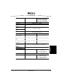
Pole (contact) assignments for 8-pole connections (plugs and jacks):
TE Side
Pins on RJ45
NT Side
Wire
Signals
3
2a
4
1a
1
not used
2
not used
Wiring
Wire
Signals
TX +
1a
TX +
RX +
2a
RX +
Resistors
5
1b
RX -
2b
RX -
6
2b
TX -
1b
TX -
7
not used
8
not used
Termination resistors
100 Ohm, 5%
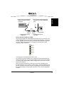
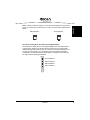
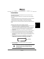
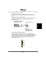
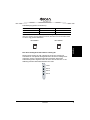
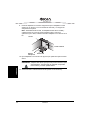
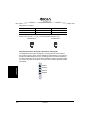
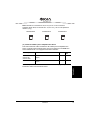
Note: Looking at the RJ45 connector with the exposed connector pins facing you,
the pins are numbered from 1 to 8 from left to right (as shown below).
8
1
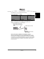
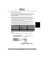
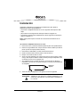
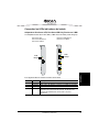
Connect your Diva Server PRI adapter
Note: Diva Server PRI adapters have a built-in CSU (channel service unit) to
protect the adapters from damage due to power surges. However, you can also
use an external CSU, which allows you to test your ISDN, E1, or T1 line.
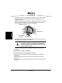
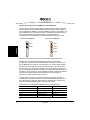
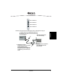
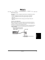
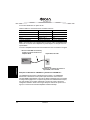
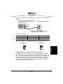
Use one of the cables included with the adapter. The cable you use depends on
how you want to apply your adapter:
• RJ45 to RJ45 for connection to an ISDN PRI, E1, or T1 line with an RJ45 jack or
for connection as network termination to a PBX.
• RJ45 to open-ended cables for connection to your ISDN PRI, E1, or T1 line with
open-ended wire connections or for back-to-back connection.
26
Installation