1
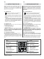
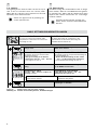
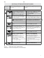
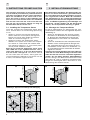
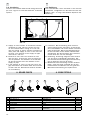
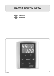
HARVIA XENIO INFRA
Control unit
Steuergerät
24032015/ZVR-861
These instructions for installation and use are intended for owners of infrared cabins, radiators and
control units, persons in charge of managing infrared cabins, radiators and control units, and for electricians responsible for installing radiators and control units. Once the control unit is installed, these
instructions of installation and use are handed over
to the owner of the infrared cabin, radiators and
control unit, or to the person in charge of maintaining them.
Diese Montage- und Gebrauchsanleitung richtet sich
an Besitzer von Infrarotkabinen, Infrarotstrahler und
Steuergeräten, an Personen, die für den Betrieb von
Infrarotkabinen, Infrarotstrahler und Steuergeräten
verantwortlich sind, sowie an Elektromonteure, die
mit der Montage von Infrarotstrahler und Steuergeräten betraut sind. Nach der Montage des Steuergeräts ist diese Montage- und Gebrauchsanleitung
dem Besitzer der Infrarotkabine, des Strahlers bzw.
des Steuergeräts oder der für die Wartung der Anlagen zuständigen Person auszuhändigen.
CONTROL UNIT HARVIA XENIO INFRA (CX36I)
Control unit's purpose of use: The control unit is
meant for controlling the functions of infrared radiators. It is not to be used for any other purpose.
steuergerät Harvia XENIO INFRA (CX36I)
Verwendungszweck des Steuergeräts: Das
Steuergerät dient zur Steuerung der Funktionen der
Infrarotstrahler. Er darf nicht für andere Zwecke
verwendet werden.
Congratulations on making an excellent choice!
Wir beglückwünschen Sie zu Ihrer guten Wahl!
Contents
Inhalt
1. HARVIA Xenio INFRA.................................................. 3
1.1. General............................................................... 3
1.1.1 Warnings..................................................... 3
1.2. Technical Data..................................................... 3
1.3. Troubleshooting................................................... 4
1. HARVIA Xenio INFRA.................................................. 3
1.1. Allgemeines......................................................... 3
1.1.1 Warnungen.................................................. 3
1.2. Technische Daten................................................ 3
1.3. Störungsbeseitigung............................................. 4
2. Instructions for use.............................................. 5
2.1. Radiators On....................................................... 5
2.2. Radiators Off....................................................... 5
2.3. Changing the Settings.......................................... 5
2.4. Lighting.............................................................. 6
2. Bedienungsanleitung.............................................. 5
2.1. Infrarotstrahler ein................................................ 5
2.2. Infrarotstrahler aus............................................... 5
2.3. Ändern der Einstellungen....................................... 5
2.4. Beleuchtung........................................................ 6
3. INSTRUCTIONS FOR Installation.............................. 8
3.1. Installing the Temperature Sensor.......................... 8
3.2. Installing the Power Unit....................................... 9
3.2.1. Electrical Connections ................................. 9
3.2.2. Multidrive................................................... 9
3.2.3. Power Unit Fuse Faults................................. 9
3.3. Installing the Control Panel.................................. 11
3.4. Ventilation ....................................................... 12
3. Installationsanleitung......................................... 8
3.1. Montage des Temperaturfühlers............................. 8
3.2. Montage der Leistungseinheit................................ 9
3.2.1. Elektrische Anschlüsse................................. 9
3.2.2. Multidrive................................................... 9
3.2.3. Sicherungsdefekte der Leistungseinheit........... 9
3.3. Montage des Bedienfelds.................................... 11
3.4. Belüftung.......................................................... 12
4. Spare parts........................................................... 12
4. ERSATZTEILE............................................................ 12
EN
DE
1. HARVIA Xenio INFRA
1. HARVIA Xenio INFRA
1.1. General
1.1. Allgemeines
1.1.1 Warnings
• This appliance can be used by children aged
from 8 years and above and persons with
reduced physical, sensory or mental capabilities or lack of experience and knowledge, if
they have been given supervision or instruction
concerning use of the appliance in a safe way
and understand the hazards involved. Children
shall not play with the appliance. Cleaning and
user maintenance shall not be made by children
without supervision.
1.1.1 Warnungen
• Dieses Gerät kann von Kindern ab 8 Jahren und
von Personen mit eingeschränkten physischen,
sensorischen oder geistigen Fähigkeiten oder
eingeschränkter Erfahrung oder Unkenntnis
benutzt werden, wenn sie in das Gerät eingewiesen wurden und eine Anweisung für den sicheren Gebrauch dieses Gerätes bekamen und
die damit verbundenen Gefahren verstanden
haben. Kinder dürfen nicht an dem Gerät herum
spielen. Die Reinigung und Pflege des Gerätes
darf von Kindern nicht ohne Aufsicht durchgeführt werden.
1.2. Technical Data
1.2. Technische Daten
The purpose of the Harvia Xenio Infra control unit
is to control 1–8 infrared radiators. The maximum
total output of the radiators is 3.6 kW. The control
unit consists of a control panel, a power unit and a
temperature sensor. See figure 1.
The control unit regulates the temperature in the
infrared cabin based on information given by the
sensor. The temperature is sensed by an NTC thermistor.
Infrared cabin
Infrarotkabine
Power unit
Leistungseinheit
Dry area
Trockener Bereich
Control panel:
• Temperature adjustment range 25–50 °C
• On-time adjustment range: 1–12 h. For
longer operating times consult the importer/
manufacturer.
• Control of lighting
• Dimensions: 85 mm x 24 mm x 110 mm
• Length of data cable: 5 m (10 m extension
cables available, max. total length 30 m)
Power unit:
• Supply voltage: 230 V 1N~
• Max. load: 3.6 kW (example: 8 x 0.45 kW)
• Lighting control, max. power 300 W,
230 V 1N~
• Dimensions: 272 mm x 70 mm x 193 mm
Der Zweck des Steuergeräts Harvia Xenio Infra ist
es, 1–8 Infrarotstrahler zu regeln. Die maximale
Gesamtleistung des Geräts beträgt 3,6 kW. Das
Steuergerät besteht aus einem Bedienfeld, einer
Leistungseinheit und einem Temperaturfühler. Siehe Abbildung 1.
Das Steuergerät reguliert die Temperatur in der
Infrarotkabine entsprechend der von dem Fühler
gelieferten Daten. Die Temperatur wird mit einem
NTC-Thermistor erfasst.
Bedienfeld:
• Temperatur-Einstellbereich: 25–50 °C
• Betriebszeit-Einstellbereich: 1–12 h. Zu längeren Betriebszeiten befragen Sie bitte den Importeur bzw. Hersteller.
• Steuerung von Beleuchtung
• Abmessungen: 85 mm x 24 mm x 110 mm
• Datakabel, Länge 5 Meter (kann mit 10 m Verlängerungskabeln bis 30 m verlängert werden)
Leistungseinheit:
• Versorgungsspannung: 230 V 1N~
• Max. Last: 3,6 kW (Beispiel: 8 x 0,45 kW)
• Beleuchtungssteuerung, max. Leistung: 300 W,
230 V 1N~
• Abmessungen: 272 mm x 70 mm x 193 mm
Control panel
Bedienfeld
WX367
Temperature sensor
(optional, 3.1.)
Data cable
Datakabel
Infrared radiators
(1–8 pcs)
Infrarotstrahler
(1–8 Stk)
Temperaturfühler
(wahlweise, 3.1.)
Main switch
Hauptschalter
Figure 1.
System components
Abbildung 1. Komponenten
3
EN
DE
Sensor (WX367):
• Temperature sensor: NTC thermistor (22 kΩ/
T=25 ºC)
• Weight: 175 g with leads, ca 4 m
• Dimensions: 51 mm x 73 mm x 27 mm
Fühler (WX367):
• Temperaturfühler: NTC-Thermistor (22 kΩ/
T=25 °C).
• Gewicht: 175 g mit Leitungen (ca 4 m)
• Abmessungen: 51 mm x 73 mm x 27 mm
1.3. Troubleshooting
1.3. Störungsbeseitigung
If an error occurs, the radiator power will cut off
and the control panel will show an error message ”E
(number)”, which helps troubleshooting the cause
for the error. Table 1.
Note! All service operations must be done by
professional maintenance personnel. No userserviceable parts inside. Replace a broken radiator
with the same model from the same manufacturer.
E1
E2
E16
Wenn eine Störung auftritt, wird die Strahler abgeschaltet, und auf dem Bedienfeld wird eine Fehlermeldung im Format “E (Nummer)” angezeigt, die
Hilfe bei der Störungsbeseitigung bietet. Tabelle 1.
Achtung! Alle Wartungsmaßnahmen müssen
von technisch qualifiziertem Personal durchgeführt
werden. Es befinden sich keine vom Benutzer zu
wartenden Teile im Gerät. Ersetzen Sie ein defektes
Heizelement stets durch dasselbe Modell desselben
Herstellers.
Description/Beschreibung
Remedy/Abhilfe
Temperature sensor's measuring
circuit broken.
Check the blue and brown wires to the temperature sensor and their
connections (see figure 7) for faulties.
Messkreis des Temperaturfühlers
unterbrochen.
Prüfen Sie die blauen und braunen Kabel zum Temperaturfühler und
deren Verbindungen (siehe Abb. 7) auf Fehler.
Temperature sensor's measuring
circuit short-circuited.
Check the blue and brown wires to the temperature sensor and their
connections (see figure 7) for faulties.
Kurzschluss im Messkreis des
Temperaturfühlers.
Prüfen Sie die blauen und braunen Kabel zum Temperaturfühler und
deren Verbindungen (siehe Abb. 7) auf Fehler.
A sensor is connected both to the
control panel and the power unit.
Only one sensor can be used ( 3.1.). Remove extra sensors.
Es ist ein Fühler sowohl am
Bedienfeld als auch an der
Leistungseinheit angebracht.
Nur ein Fühler kann benutzt werden ( 3.1.). Entfernen Sie die
anderen Fühler.
Table 1. Error messages. Note! All service operations must be done by professional maintenance personnel.
Tabelle 1. Fehlermeldungen. Achtung! Alle Wartungsmaßnahmen müssen von qualifiziertem technischem Personal
durchgeführt werden.
4
EN
DE
2. Instructions for use
2. Bedienungsanleitung
When the control unit is connected to the power
supply and the main switch (see figure 1) is
switched on, the control unit is in standby mode
and ready for use. I/O button’s background light
glows on the control panel.
Wenn das Steuergerät an die Stromversorgung angeschlossen ist und der Hauptschalter (siehe Abbildung 1) betätigt wird, befindet sich das Steuergerät im Standby-Modus und ist betriebsbereit.
Die Kontrollleuchte der I/O-Taste leuchtet auf dem
Bedienfeld.
2.1. Radiators On
2.1. Infrarotstrahler ein
Switch the radiators on by pressing the
I/O button on the control panel.
When the radiators switch on, the top row of the
display will show the set temperature and the
bottom row will show the set on time for five
seconds.
When the desired temperature has been reached
in the infrared cabin, the radiators are automatically
switched off. To maintain the desired temperature,
the control unit will automatically switch the
radiators on and off in periods.
2.2. Radiators Off
Drücken Sie auf dem Bedienfeld die I/O Taste, um die Strahler einzuschalten.
Beim Einschalten des Strahlers zeigt die obere
Zeile des Displays die eingestellte Temperatur,
während die untere Zeile fünf Sekunden lang die
Einschaltzeit anzeigt.
Sobald die gewünschte Temperatur in der Infrarotkabine erreicht wurde, werden die Strahler
automatisch ausgeschaltet. Um die gewünschte
Temperatur beizubehalten, schaltet das Steuergerät die Strahler in regelmäßigen Zeitabständen
ein und aus.
2.2. Infrarotstrahler aus
The radiators turn off and the control unit switches
to standby-mode when
• the I/O button is pressed
• the on-time runs out or
• an error occurs.
NOTE! It is essential to check that the control
unit has cut power off from the radiators after the
on-time has elapsed or the radiators have been
switched off manually.
Die Strahler wird ausgeschaltet und das Steuergerät
schaltet in den Standby-Modus um, wenn
• die I/O-Taste gedrückt wird
• die eingestellte Einschaltzeit abläuft oder
• ein Fehler auftritt.
ACHTUNG! Prüfen Sie unbedingt, ob die Stromversorgung zum Strahler getrennt ist, nachdem die
Einschaltzeit abgelaufen ist oder die Strahler manuell ausgeschaltet werden.
2.3. Changing the Settings
2.3. Ändern der Einstellungen
The settings menu structure and changing the
settings is shown in figures 3a and 3b.
The programmed temperature value and all values
of additional settings are stored in memory and will
also apply when the device is switched on next
time.
Die Struktur des Einstellungsmenüs und das Ändern
der Werte wird in den Abbildungen 3a und 3b gezeigt.
Der programmierte Temperaturwert und alle weiteren Einstellungswerte werden gespeichert und auch
beim nächsten Einschalten des Geräts verwendet.
Display
Anzeige
Indicator lights
Kontrollleuchte
Temperature
On-time
Temperatur
Einschaltzeit
Menu and navigation buttons
Value decrease *)
Mode change
Value increase *)
*) Press and hold to make
the value change faster.
Operating buttons
Radiators on/off
Lighting on/off
Menü- und Navigationstasten
Wert verringern *)
Modus wechseln
Wert erhöhen *)
*) Gedrückt halten, damit die
Werte sich schneller ändern.
Bedientasten
Strahler ein/aus
Beleuchtung ein/aus
Figure 2.
Control panel
Abbildung 2. Bedienfeld
5
EN
DE
2.4. Lighting
2.4. Beleuchtung
The lighting of the infrared cabin can be set up so
that it can be controlled from the control panel.
(Max 300 W.) Lighting can be switched on and off
separately from other functions.
Switch the lights on/off by pressing the
control panel button.
Die Beleuchtung der Infrarotkabine kann so eingestellt werden, dass sie vom Bedienfeld aus gesteuert werden kann. (Max. 300 W.) Beleuchtung kann
separat über andere Funktionen ein- und ausgeschaltet werden.
Schalten Sie die Lampen ein oder aus,
indem Sie die Taste auf dem Bedienfeld
drücken.
Basic settings/GRUNDEINSTELLUNGEN
Basic mode (radiators on)
The top row shows the infrared cabin
temperature. The bottom row shows the
remaining on-time.
Basis-Modus (Strahler ein)
Die obere Zeile zeigt die Temperatur in der
Infrarotkabine an. Die untere Zeile zeigt die
verbleibende Einschaltzeit an.
Press the MENU button to open the
settings menu.
Öffnen Sie das Einstellungsmenü, indem Sie die
MENU-Taste drücken.
Infrared cabin temperature
Temperatur in der Infrarotkabine
The display shows the infrared cabin
temperature setting.
• Change the setting to the desired
temperature with the – and + buttons.
The range is 25–50 ºC.
Das Display zeigt die Temperatureinstellung für
die Infrarotkabine an.
• Ändern Sie die Einstellung mit den Tasten
– und + auf die gewünschte Temperatur.
Der Einstellbereich beträgt 25–50 °C.
Press the MENU button to access the next Gehen Sie zur nächsten Einstellung über, indem
setting.
Sie die MENU-Taste drücken.
Remaining on-time
Press the – and + buttons to adjust the
remaining on-time.
Example: the radiators will be on for 3
hours and 30 minutes.
Press the MENU button to exit.
Figure 3a. Settings menu structure, basic settings
Abbildung 3a. Struktur des Einstellungsmenüs, Grundeinstellungen
6
Verbleibende Einschaltzeit
Stellen Sie mit den Tasten – und + die
verbleibende Einschaltzeit ein.
Beispiel: Die Strahler werden 3 Stunden und
30 Minuten lang laufen.
Drücken Sie die MENU-Taste, um die
Einstellungen zu beenden.
EN
DE
Additional settings/WEITERE EINSTELLUNGEN
Control unit standby
I/O button’s background light glows on the
control panel.
Standby des Steuergeräts
Die Kontrollleuchte der I/O-Taste leuchtet auf dem
Bedienfeld.
Open the settings menu by simultaneously
pressing the locations of the buttons –,
MENU and + (see figure 2). Press for 5
seconds.
The buttons do not glow when the
control unit is in standby mode.
Öffnen Sie das Einstellungsmenü, indem Sie
gleichzeitig die Taste -, MENU und + drücken
(siehe Abb. 2). Halten Sie die Tasten 5
Sekunden lang gedrückt.
Im Standbye Modus leuchten die Tasten
nicht.
Maximum on-time
Maximale Einschaltzeit
The maximum on-time can be changed
with the – and + buttons. The range is
1–12 hours (1 hour*)).
Example: the radiators will be on for 1
hour from the start. (Remaining on-time
can be changed, see figure 3a.)
Die maximale Einschaltzeit kann mit den Tasten – und + geändert werden. Der Einstellbereich beträgt 1 bis 12 Stunden (1 Stunde*)).
Beispiel: Die Strahler wird von Beginn an eine
Stunde lang laufen. (Die verbleibende Einschaltzeit kann geändert werden, siehe Abb. 3a).
Press the MENU button to access the next
setting.
Gehen Sie zur nächsten Einstellung über,
indem Sie die MENU-Taste drücken.
Sensor reading adjustment
Einstellung des Fühlerwerts
Press the MENU button to access the next
setting.
Gehen Sie zur nächsten Einstellung über,
indem Sie die MENU-Taste drücken.
Memory for power failures
Speicher für Stromausfälle
Press the MENU button. The control unit
switches to standby-mode.
Drücken Sie die MENU-Taste. Das Steuergerät
schaltet in den Standby-Modus um.
The reading can be corrected by +/- 5
units. The adjustment does not affect the
measured temperature value directly, but
changes the measuring curve.
Die Messwerte können um +/- 5 Einheiten
korrigiert werden. Die Einstellung betrifft nicht
den gemessenen Temperaturwert direkt, sondern ändert die Messkurve.
The memory for power failures can be
Der Speicher für Stromausfälle kann ein- oder
turned ON or OFF*).
ausgeschaltet werden (ON oder OFF*)).
• When turned on, the system will start
• Durch das Einschalten wird das System nach
again after a break in electricity.
einem Stromausfall neu gestartet.
• When turned off, the break will shut
• Durch das Abschalten wird das System herthe system down. I/O button must be
untergefahren. Für einen Neustart muss die
pressed to restart.
I/O-Taste gedrückt werden.
• The safety regulations for memory usage • Die Sicherheitsvorschriften für die Verwenvary from region to region.
dung des Speichers können je nach Region
variieren.
*) Factory setting/Werkseinstellung
Figure 3b. Settings menu structure, additional settings
Abbildung 3b. Struktur des Einstellungsmenüs, weitere Einstellungen
7
EN
DE
3. INSTRUCTIONS FOR Installation
3. Installationsanleitung
The electrical connections of the control unit may
only be made by an authorised, professional electrician and in accordance with the current regulations.
When the installation of the control unit is complete, the person in charge of the installation must
pass on to the user the instructions for installation
and use that come with the control unit and must
give the user the necessary training for using the
infrared cabin and the control unit.
Die elektrischen Anschlüsse des Steuergeräts dürfen nur von einem autorisierten, geschulten Elektriker unter Beachtung der aktuell gültigen Vorschriften vorgenommen werden. Nach der Installation
des Steuergeräts ist der verantwortliche Monteur
verpflichtet, dem Benutzer die mitgelieferte Installations- und Bedienungsanleitung auszuhändigen und
der Person, die den Strahler und das Steuergerät
bedient, eine entsprechende Schulung zu geben.
3.1. Installing the Temperature Sensor
3.1. Montage des Temperaturfühlers
B
min. 1000 mm
A
Figure 4.
Options for sensor type and placement
Abbildung 4.Optionen für Fühlertyp und Anbringung
00
>10
360°
mm
m
0m
>50
180°
Figure 5.
Sensor’s minimum distance from an air vent
Abbildung 5.Mindestabstand des Fühlers zu Luftschlitzen
8
Es gibt 2 möglichkeiten zur Anbringung des Temperaturfühlers. Wählen Sie der folgenden Optionen
(Abbildung 4).
• Option A: Schließen Sie den internen Temperaturfühler im Bedienfeld an (siehe Abbildung
9). Bringen Sie das Bedienfeld innerhalb der
Infrarotkabine in einer Höhe von mindestens
1 m an.
• Option B: Verbinden Sie den Temperaturfühler
WX367 mit der Leistungseinheit. Bringen Sie
den Temperaturfühler an einer Wand in der Infrarotkabine in einer Höhe von mindestens 1 m
an. Das Bedienfeld kann außerhalb der Kabine
angebracht werden.
Achtung! Der Temperaturfühler darf nicht näher als
1000 mm an einen Mehrrichtungs-Luftschlitz oder
näher als 500 mm an einen Luftschlitz angebracht
werden, der vom Fühler wegzeigt. Siehe Abbildung
5. Der Luftzug in der Nähe von Luftschlitzen kühlt
den Fühler ab, was zu ungenauen Temperaturmessungen am Steuergerät führt. Dies kann zu einer
Überhitzung des Strahlers führen.
min. 1000 mm
There are 2 options for temperature sensor placement. Choose either of the following options (figure 4).
• Option A: Connect the internal temperature
sensor inside the control panel (see figure 9).
Fasten the control panel inside the infrared
cabin at a minimum height of 1 m.
• Option B: Connect the temperature sensor
WX367 to the power unit. Fasten the temperature sensor to a wall inside the infrared cabin
at a minimum height of 1 m. The control panel
can be placed outside the cabin.
Note! Do not install the temperature sensor closer
than 1000 mm to an omnidirectional air vent or
closer than 500 mm to an air vent directed away
from the sensor. See figure 5. The air flow near an
air vent cools down the sensor, which gives inaccurate temperature readings to the control unit. As
a result, the radiators might overheat.
EN
DE
3.2. Installing the Power Unit
3.2. Montage der Leistungseinheit
Install the power unit outside the infrared cabin, in
a dry place with an ambient temperature of >0 ºC.
See figure 6 for instructions on how to open the
power unit cover and how to mount the unit.
Note! Do not embed the control unit into structures, since this may cause excessive heating of
the internal components of the unit and lead to
damage. Allow proper ventilation around the unit.
See figure 6.
Bringen Sie die Leistungseinheit an einem trockenen
Ort außerhalb der Infrarotkabine mit einer Umgebungstemperatur von über 0 ºC. In Abbildung 6 finden Sie Anweisungen zum Öffnen der Abdeckung
der Leistungseinheit sowie zur Anbringung an einer
Wand bzw. auf der Dach.
Achtung! Die Leistungseinheiten dürfen nicht in
die Wand oder das Dach gesenkt werden, da dies
zu einer Überhitzung der internen Gerätekomponenten und daraus resultierenden Schäden führen
kann. Achten Sie darauf, dass genügend Luftzirkulation rundum der Gehäuse gewährleistet ist. Siehe
Abbildung 6.
Figure 6.
Opening the power unit cover and mounting the unit
Abbildung 6. Öffnen der Abdeckung der Leistungseinheit und Wand-/Deckenmontage des Geräts
3.2.1. Electrical Connections
Figure 7 shows the electrical connections of the
power unit. Also see the instructions for installation
delivered with the infrared radiators.
The connecting cable must be of rubber cable
type H07RN-F if the wiring from the infrared radiator is not inside the structures. Primarily the
wiring should be inside the structures (outside the
insulating layer).
Note! If the mains cable is damaged, the manufacturer or its service agent or an equivalent qualified person has to replace it to avoid hazards.
3.2.1. Elektrische Anschlüsse
Abbildung 7 zeigt die elektrischen Anschlüsse der
Leistungseinheit. Siehe auch die mit den Infrarotstrahlern gelieferten Installationsanweisungen.
Das Verbindungskabel muss ein Gummikabel des
Typs H07RN-F sein, wenn sich die Verkabelung des
Infrarot-Heizelements nicht innerhalb der Konstruktion befindet. Die Verkabelung sollte vorzugsweise
innerhalb der Konstruktion erfolgen (Außerhalb der
Isolierschicht).
Achtung! Wenn das Netzkabel defekt ist, muss es
durch den Hersteller, sein Wartungspersonal oder
eine andere entsprechend qualifizierte Person ausgetauscht werden, um Gefahren vorzubeugen.
3.2.2. Multidrive
Up to 8 power units can be connected in series
so that they share the same control panel. The
connection principle is shown in figure 8.
Only one temperature sensor can be used. The
sensor must either be connected to the first power
unit in the chain or to the control panel ( 3.1.).
3.2.2. Multidrive
Bis zu 8 Leistungseinheiten können seriell miteinander verbunden werden, so dass sie sich über
das gleiche Bedienfeld regeln lassen. Das Anschlussschema ist in Abbildung 8 dargestellt.
Es kann nur ein Temperaturfühler verwendet werden. Der Fühler wird entweder an das erste Leistungsgerät der Kette oder an das Bedienfeld angeschlossen ( 3.1.).
3.2.3. Power Unit Fuse Faults
Replace a blown fuse by a new one with the same
value. The placement of the fuses in the power unit
is shown in figure 7.
• If the fuses for relay outputs have blown, there
is a problem with lighting. Check the wiring
and functioning of lighting.
3.2.3. Sicherungsdefekte der Leistungseinheit
Ersetzen Sie eine defekte Sicherung gegen eine Sicherung desselben Werts. Die Position der Sicherungen in der Leistungseinheit ist in Abbildung 7
dargestellt.
• Ist die Sicherungen für die Relaisausgänge defekte, so liegt ein Problem mit Beleuchtung vor.
Prüfen Sie Verkabelung und Funktionsweise
von Beleuchtung.
9
EN
DE
ZVR-862/A
Figure 7. Electrical connections
Abbildung 7. Elektrische Anschlüsse
Figure 8. Power unit chain (Multidrive)
Abbildung 8. Kette der Leistungseinheiten (Multidrive)
10
EN
DE
3.3. Installing the Control Panel
3.3. Montage des Bedienfelds
Install the control panel in or outside the infrared
cabin, in a dry place with an ambient temperature
of >0 ºC where it can be accessed conveniently.
See figure 9.
1. Thread the data cable through the hole in
the back cover.
2. Fasten the back cover to a wall with
screws.
3. Push the data cable to the connector.
4. Connect the temperature sensor (see
options in section 3.1.)
5. Press the front cover into the back cover.
Bringen Sie das Bedienfeld innerhalb oder außerhalb der Infrarotkabine an einem trockenen Ort mit
einer Umgebungstemperatur von über 0 ºC an, wo
es leicht zugänglich ist. Abbildung 9.
1. Datakabel des Bedienfelds durch die Öffnung in der
Rückwand führen.
2. Hintere Abdeckung mit Schrauben an einer Wand
fixieren.
3. Datakabel in den Stecker schieben.
4. Schließen Sie den Temperaturfühler an (siehe Optionen
in Abschnitt 3.1.).
5. Vordere Abdeckung auf die hintere Abdeckung drücken.
5.
3,5 x 15 mm
2.
3.
4.
1.
Figure 9. Fastening the control panel
Abbildung 9. Befestigung des Bedienfelds
11
EN
DE
3.4. Ventilation
3.4. Belüftung
The air in the infrared cabin should change six times
per hour. Figure 10 illustrates different ventilation
options.
Der Luftaustausch sollte sechsmal in der Stunde
stattfinden, maßgebend ist das Raumvolumen der
Kabine. Abb. 10 zeigt verschiedene Optionen der
Belüftung.
C
A
A
B
Figure 10.
Abb. 10.
A.Supply air vent location. If mechanical exhaust
ventilation is used, place the supply air vent
on the infrared cabin’s ceiling or on the wall
near the ceiling. If gravity exhaust ventilation is
used, place the supply air vent on the wall near
the floor. The diameter of the supply air pipe
must be 50–100 mm.
B. Exhaust air vent. Place the exhaust air vent
near the floor, as far away from the supply air
vent as possible. The diameter of the exhaust
air pipe should be twice the diameter of the
supply air pipe.
C.If the exhaust air vent is in the next room, the
gap underneath the infrared cabin door must be
at least 100 mm. Mechanical exhaust ventilation is mandatory.
A.Luftzufuhr. Bei Verwendung einer mechanischen Lüftung ist die Luftzufuhr an der Decke
der Infrarotkabine oder an der Wand in Deckennähe anzubringen. Bei Schwerkraftentlüftung
ist die Luftzufuhr an der Wand in Bodennähe
anzubringen. Der Durchmesser des Luftzufuhrrohres muss 50–100 mm betragen.
B. Entlüftung. Entlüftung möglichst weit entfernt
von der Zuluft in Bodennähe anbringen. Der
Durchmesser des Entlüftungsrohres sollte doppelt so groß sein wie bei der Zuluft.
C.Befindet sich die Entlüftung in einem anderen
Raum, muss der Spalt unterhalb der Tür der
Infrarotkabine mindestens 100 mm groß sein.
Mechanische Entlüftung ist verpflichtend.
4. Spare parts
4. ERSATZTEILE
1
1
2
3
4
5
6
7
12
2
3
4
Control panel (CX36I)
Data cable 5 m
Data cable extension 10 m (optional)
Temperature sensor
Circuit board
Multidrive cable 1,5 m (optional)
Additional power unit for Multidrive, incl. WX312
(optional)
5
6
7
Bedienfeld (CX36I)
Datakabel 5 m
Verlängerungskabel 10 m (wahlweise)
Temperaturfühler
Platine
Multidrive-Kabel 1,5 m (wahlweise)
Multidrive-Leistungseinheit, inkl. WX312
(wahlweise)
WX382
WX311
WX313
WX367
WX366
WX312
CX36IL