1
VIPCAM-GNSD88 2
VIPCAM-GNSD68 2
Integrierte High-Speed IP-Dome System-Kameras
Integrated High Speed *1Dome System Cameras
Installationsanleitung
Installation Manual
Einführung
Allgemeines
Vielen Dank für Ihre Entscheidung, ein Gerät aus der GEUTEBRÜCK Systemreihe zu erwerben.
Seit Jahren setzt GEUTEBRÜCK Qualitätsmaßstäbe in der Mikroprozessorgesteuerten Sicherheitstechnik. Die in unseren Geräten eingesetzte Technologie ist das Ergebnis der eigenen
Entwicklung und ausgewählter Lieferanten. Deshalb ist das optimale Zusammenwirken der von
GEUTEBRÜCK angebotenen Komponenten garantiert.
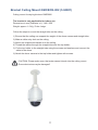
Die integrierten Hochgeschwindigkeits-Dome GNSD882 und GNSD682 sind speziell für CCTVAnwendungen konzipiert.
Der GNSD882 kann bei Temperaturen zwischen -50 °C und +50 °C im Außenbereich,
der GNSD682 bei Temperaturen zwischen 0 °C und +45 °C im Innenbereich eingesetzt werden.
Inhalt der Anleitung
Dieses Manual gilt für beide Speed-Dome-Typen. Abweichungen bzgl. technischer Details, der
Befestigung/Installation, usw., werden an den entsprechenden Stellen getrennt beschrieben. Die
Beschreibung zeigt Ihnen, wie Sie Ihr High-Speed Dome-System komplett, mit allen Video- und
Steueranschlüssen, in Betrieb nehmen können.
Bitte lesen Sie unbedingt alle verfügbaren Beschreibungen, um Ihr System vollständig in Betrieb
nehmen und bedienen zu können!
Elektromagnetische Verträglichkeit (EMC)
Dieses Gerät ist CE zertifiziert. In elektronisch empfindlicher Umgebung kann es trotzdem zu
Störungen kommen. In diesen Fällen kann es notwendig sein, weitere Schutzmaßnahmen
(Abschirmung) zu ergreifen. Dieses Produkt entspricht der EMC Direktive 89/336 und der
Niederspannungsverordnung LVD 73/23 EEC, der Norm EN 55022 für Störstrahlung, IEC 801
Part 2, 3 und 4, für externe Störfestigkeit und der Norm EN 60095 für elektrische Sicherheit.
Bitte beachten!
Wir weisen darauf hin, dass für die Netzwerkanbindung der VIPCAM Dome Netzwerkkabel
mindestens der Kategorie CAT 5 oder besser verwendet werden sollten.
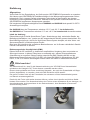
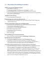
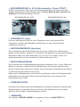
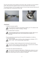
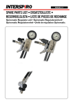
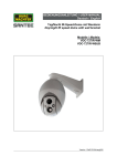
Ebenso sind unmittelbar am Dome sowohl das Netzwerk-, als auch das Systemkabel mit Klappferriten (siehe Bilder) zu versehen, damit die EMV-Richtlinien erfüllt werden.
Der graue Ferritkern wird auf das Powerkabel, der schwarze auf das Netzwerkkabel gesetzt
und danach zusammengedrückt.
Damit sich die Ferrite nicht weiter absetzen können, sollten sie mit jeweils zwei kleinen Kabelbindern fixiert werden. Der Abstand zwischen den Ferriten muss mindestens 40 mm betragen, da
sie nebeneinander nicht gemeinsam in den Deckenabstand-, bzw. Masthalter (Gooseneck /
Schwanenhals) passen.
1
Hinweis
Alle Informationen in dieser Bedienungsanleitung gelten ab der Veröffentlichung. Die
GEUTEBRÜCK GmbH behält sich das Recht vor, alle technischen Daten, die in dieser Anleitung
genannt sind, ohne Vorankündigung zu ändern.
Urheberrecht
Diese Anleitung ist urheberrechtlich geschützt. Ohne vorherige Genehmigung der GEUTEBRÜCK
GmbH ist es nicht gestattet, diese Anleitung zu kopieren, zu übersetzen, oder auf ein
elektronisches Medium zu übertragen. Es ist ebenfalls nicht gestattet, den Inhalt in ein
maschinenlesbares Format umzuformen. Das gilt auch für Teile dieser Anleitung.
©Copyright 2012, GEUTEBRÜCK GmbH.
Wichtiger Hinweis
Vor Inbetriebnahme lesen Sie bitte erst alle Anweisungen und Warnungen, die in dieser Anleitung
enthalten sind, sorgfältig durch. Bei Unklarheiten wenden Sie sich bitte an Ihren Händler. Bitte
bewahren Sie diese Anleitung und die Originalrechnung für eventuelle spätere Garantiefälle auf.
Beim Auspacken achten Sie auf eventuell fehlende und/oder beschädigte Teile. In diesem Fall
benachrichtigen Sie umgehend Ihren Händler, bevor Sie mit der Inbetriebnahme beginnen. Er wird
alles Notwendige veranlassen. Wir bedanken uns, dass Sie sich für ein GEUTEBRÜCK-Produkt
entschieden haben und wünschen Ihnen eine dauerhafte und einwandfreie Funktion. Sollte dies
einmal nicht der Fall sein, wenden Sie sich bitte an Ihren Händler oder an die GEUTEBRÜCK
GmbH, Abteilung Qualitätswesen,
Tel.:+49(0)2645 137-0.
2
Sicherheitshinweise zur Montage, Installation und Inbetriebnahme
• Behandeln Sie das Dome-System pfleglich
• Demontieren Sie das vormontierte Dome - System nicht.
Ausnahme: Wenn Sie ausdrücklich in dieser Anleitung dazu aufgefordert werden.
Führen Sie nur die beschriebenen Maßnahmen aus.
• Verschließen Sie keine Öffnungen für Lüftung und Kühlung.
• Betreiben Sie das Dome-System nur bei den spezifizierten Temperatur- und
Luftfeuchtigkeitswerten.
Betreiben Sie die Dome - Kamera nur bei Temperaturen wie vor angegeben und einer
relativen Luftfeuchtigkeit kleiner 90 % (nicht kondensierend).
Der GNSD882 besitzt die Schutzklasse IP66 für den Außenbereich, der GNSD682
eignet sich AUSSCHLIESSLICH für Innenräume.
• Montieren Sie das Dome System nur an einem geeigneten, stabilen und
schwingungsfreien Montageort.
• Richten Sie die Kamera nicht mit dem Objektiv in die Sonne.
Wenn die Kamera auf die Sonne oder andere extrem helle Objekte ausgerichtet wird,
können starke Bildstörungen wie Blooming (ein weißer Nebel umgibt diese Objekte)
und/oder Smear (das sind vertikal verlaufende weiße Striche, die von diesen Objekten
ausgehend über die gesamte Bildhöhe verlaufen können) auftreten. Außerdem kann
der Bildsensor dabei beschädigt werden.
• Benutzen Sie keine scharfen, schleifenden oder sonstige aggressiven
Reinigungsmittel für das Gehäuse.
Ein weiches Tuch (Baumwolle) und ein mildes Reinigungsmittel sind ausreichend. Nur
leicht reiben.
Arbeiten Sie nur am Schwenk-/Neigekopf, wenn sicher ist, dass keine
Netzspannung anliegt. Netzstecker ziehen und gegen Wiedereinstecken sichern.
Unfallgefahr!
3
Inhalt
1. Überblick .......................................................................................................... 6
1.1 Besondere Produkteigenschaften ............................................................................ 7
2. Installation / Inbetriebnahme GNSD882 / GNSD682 .................................... 8
2.1.1 Lieferumfang GNSD882 ....................................................................................... 8
2.1.2 Lieferumfang GNSD682 ........................................................................................ 9
2.1.3 Schalterbeschreibung und Einstellung .................................................................. 10
2.1.4 Dome - Kamera Fernsteuerprotokoll (Schalter D) ................................................. 11
2.1.5 22-polige Steckerbelegung ................................................................................... 12
2.1.6 Alarm Kontakt Beschreibung ................................................................................ 13
2.2 Installation / Inbetriebnahme des GNSD882
14
2.3
Installation / Inbetriebnahme des GNSD682 ......................................................... 17
2.3.1 Innen-Dome Installation ........................................................................................ 17
2.3.1.1 Deckenmontage .............................................................................................. 17
2.3.1.2 Wandmontage mit Wandhalter ........................................................................ 24
2.4
Systemvarianten für die Bedienung von IP-Domen mit dem Bediengerät MBeg/GCT-3X-LAN .... 25
2.5
Programmierung von IP-Domen in GSC-Setup .................................................... 28
2.5.1 Programmierung von VIPCAM-Domen in GSC-Setup .......................................... 29
3. Bedienung und Einstellung ........................................................................... 36
3.1
3.2
3.3
OSD Menü Anzeigeformat .................................................................................... 36
OSD Menü Baumstruktur ...................................................................................... 37
Einstellungsmenü.................................................................................................. 40
OSD-EINSTELLUNG mit dem GEUTEBRÜCK Bediengerät MBeg/GCT ............. 40
OSD-EINSTELLUNG via GscTelecontrol ............................................................. 41
LANDESSPRACHE .............................................................................................. 41
STANDARD (Werkeinstellung) KAMERA ............................................................. 41
GEGENLICHT(Gegenlichtkompensation) ............................................................. 41
FOKUS ................................................................................................................. 42
AE MODUS (Automatische Belichtungsregelung) ................................................ 42
WBC MODUS (Weißbalance) ............................................................................... 43
EINSTELLMENÜ 1 ............................................................................................... 44
3.3.1
3.3.2
3.3.3
3.3.4
3.3.5
3.3.6
3.3.7
•
•
•
ZOOMGESCHWINDIGKEIT ............................................................................. 44
DIGITALER ZOOM ........................................................................................... 44
LANGZEITBELICHTUNG (slow shutter) ........................................................... 44
•
•
•
•
•
•
BILDUMKEHRUNG .......................................................................................... 45
STANDBILD (Freeze) ....................................................................................... 45
KANTENANHEBUNG (Apertur) ........................................................................ 45
BILDSTABILISIERUNG .................................................................................... 45
STABILER ZOOM............................................................................................. 45
BEENDEN ........................................................................................................ 45
4
3.3.8
EINSTELLMENÜ 2 ............................................................................................. 46
•
•
•
•
•
DREHEN (FLIP/elektronische oder mechanische Bildumkehr) ........................ 46
WINKELJUSTIERUNG (Min/Max) .................................................................... 47
GESCHWINDIGKEIT PRO ZOOM ................................................................... 47
AUTOKALIBRIERUNG ..................................................................................... 47
PASSWORT .................................................................................................. 47
•
•
•
SYSTEM RESET (Zurückstellen) ................................................................. 47
SCAN MODUS ............................................................................................. 47
BEENDEN (EXIT) ............................................................................................. 47
3.3.9
ID ANZEIGE ..................................................................................................... 48
3.3.10 TITEL ANZEIGE (Kamera - Titeleinblendung) .................................................. 48
3.3.11 TITEL EINSTELLUNG ...................................................................................... 48
3.3.12 VORGABE FESTPOSITIONEN........................................................................ 49
3.3.13 SEQUENZ ........................................................................................................ 49
3.3.14 AUTOMATISCHES SCHWENKEN .................................................................. 50
3.3.15 KAMERAFAHRT .............................................................................................. 52
3.3.16 STARTEINSTELLUNG ..................................................................................... 52
3.3.17 IR FUNKTION (Zuschaltbarer IR Cut Filter) ..................................................... 54
3.3.18 ALARMEINSTELLUNG .................................................................................... 55
3.3.18.1 ALARMERKENNUNG ..................................................................................... 57
3.3.19 WDR FUNKTION (Erweiterter Dynamikbereich) ................................................ 59
3.3.20 PRIVACY MASK (ESF Elektronische Sichtschutzfunktion) ................................ 60
3.3.21 ZEITEINSTELLUNG (Uhrzeit/Datum-Funktion) .................................................. 61
3.3.22 ZEITPLAN (Termin/Zeitplanung) ........................................................................ 62
3.3.23 BEENDEN OSD ................................................................................................. 63
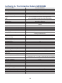
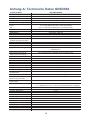
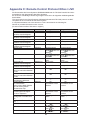
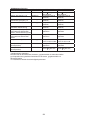
Anhang A: Technische Daten GNSD882 / GNSD682 ........................................64
Steuerprotokolle JVC TK-C 676E (im Anhang d. engl. Manuals)
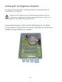
Anhang B: Verfügbares Zubehör........................................................................66
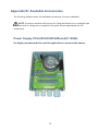
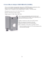
Netzteil PSU-24VAC/80VA/Boxed (5.14040) .................................................................. 66
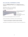
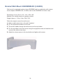
Bracket Wall Mount GSD/BWM-003 (5.04802) ............................................................... 67
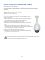
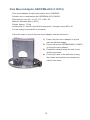
Bracket Ceiling Mount GSD/BCE-002 (5.04801) ............................................................. 68
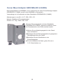
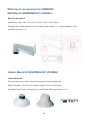
Corner Mount Adapter GSD/CMA-003 (5.04806) ............................................................ 69
Pole Mount Adapter GSD/PMA-003 (5.18374) ................................................................ 70
Montagezubehör für GNSD682 ...........................................................................71
Wandhalter GSD/BWM-001 (5.04864) ............................................................................ 71
Dome Montageadapter (5.04866) ................................................................................... 71
Deckeneinbausatz GSD/BFC-001 (5.04860) .................................................................. 72
Deckenhalter GSD/BPE-001 (5.04862) ........................................................................... 73
5
1. Überblick
Beide Speeddome-Typen beinhalten das gleiche Kamera-Zoomblock-Modul.
Das integrierte High-Speed Dome-Kamera-Modul verfügt über die neueste Generation
besonders leistungsfähiger DSP-Farbkameras, mit 36-fach optischem und 12-fachem
Digital Zoom. Durch diese hohe Zoomfähigkeit erlaubt die Kamera einen klaren Blick,
auch über große Distanzen. Ergänzt durch Auto-Fokus, Gegenlicht-Kompensation,
automatische Belichtungsregelung AES, ausschwenkbares IR-Sperrfilter, Privacy
Masking (ESF - elektronische Sichtschutzfunktion) und Wide Dynamic Range (WDR),
wird so unter fast allen Umständen eine möglichst optimale Bildqualität erreicht.
Eine sog. "Home-Funktion" ermöglicht es, nach einer variabel einstellbaren Zeit entweder
eine bestimmte "Home Position" einzunehmen, bzw. eine bestimmte Funktion, z.B.
Sequenz, Autoschwenken, Kamerafahrt, auszuführen.
Der Dome bietet variable Schwenk- und Neigegeschwindigkeiten im Bereich von 0,5°/s
bis zu 400°/s. Das ergibt eine wesentlich bessere Steuerbarkeit gegenüber
konventionellen Antrieben. Der Schwenkbereich beträgt 360° (Endlos-Drehung). Der
Neigebereich reicht von -10° bis +100°. So kann der Dome auch Objekte bis zu 10°
oberhalb der Waagerechten (in beiden Richtungen) erfassen. Damit ist eine
kontinuierliche Objektverfolgung gewährleistet. Es können bis zu 256 Positionen
(Presets), 8 Sequenzen, 4 Auto-Schwenk-Variationen und 4 Kamera-Fahrten (Touren)
programmiert werden. Die Kommunikation der Fernsteuerung erfolgt bis zu 1.200 m
Entfernung über eine RS-485-Schnittstelle.
Die Dome-Kamera verfügt über 7 + 1* Alarmeingänge (z.B. lokale Sensoren) und einen
Alarmausgang. Diese können vorprogrammierte Funktionen wie Preset, Autopan,
Sequence oder Tour auslösen. Die Alarmreaktionen werden über das "On Screen Menü"
(OSD) programmiert. Ein zusätzlicher Eingang kann zur externen (manuellen)
Umschaltung zwischen Farb- (Tag) und SW- (Nacht) Betrieb genutzt werden. Hierüber
können eine oder mehrere Dome - Kameras (z. B. mit einem Dämmerungsschalter)
zwischen Farbe und SW umgeschaltet werden. Die Funktion "Home Position" erlaubt es,
die Dome - Kamera in eine programmierbare Grundposition fahren zu lassen. Diese
Funktion kann auch zeitabhängig ausgelöst werden.
(* = Alarmeingang 8 dient für die externe Tag/Nacht-Umschaltung; offen = Tagbetrieb,
geschlossen = Nachtbetrieb).
Fertigung und Test jeder Dome - Kamera unterliegen den strengen Anforderungen der
DIN/ISO 9001-Vorschriften.
6
1.1 Besondere Produkteigenschaften
Präzise und genaue Objektverfolgung
• Automatischer Abgleich
• Positionsgenauigkeit für Schwenken und Neigen: +- 0.225°
• Geschwindigkeit beim Anlaufen von Festpositionen: bis zu 400°/s.
• Die Schwenk-/Neigegeschwindigkeiten können proportional zur eingestellten
Brennweite gewählt werden.
Tag/Nacht-Umschaltung
• Ausschwenkbares lR Sperrfilter
Anwendungen bei schwacher Beleuchtung
• Minimale Beleuchtungsstärke 0,01 Lux (S/W) mit Slow Shutter Integration
(Mehrfachabtastung)
Perfekte Kontrastübertragung für hohe Bildqualität
• Erweiterter Dynamik-Bereich durch WDR (Wide Dynamic Range)
• Automatischer Weißabgleich (AWB)
• Automatische Verstärkungsregelung (AGC)
• Backlight Compensation (BLC)
• Automatische Blendenregelung
• Alarmerkennung
• Bildumkehrung
Privacy Masking für Privatsphärenschutz
• Bis zu 24 Zonen programmierbar (unabhängig, überlappend)
Dynamische Dome-Konfiguration
• Flexible Montagehilfen für Innen- und Außenanwendung
• Kompaktes und leichtes Gehäusedesign für einfache Installation
• Wetterfestes Gehäuse für Einsatz bei unterschiedlichen Temperaturen,
Sonneneinstrahlung und Regen (gilt nur für den GNSD882!).
Video-DSP und Ethernet/IP-Interface zur GeViScope System-Integration:
• Der DSP (Digital Signal Processor) in dieser Kamera ist ein Hochleistungs-VideoDSP, der speziell für die Integration der Kamera in das GEUTEBRÜCK
GeViScope-System vorgesehen ist. Dieser DSP übernimmt alle Funktionen der
Bildvorverarbeitung, wie sie auch im GeViScope ausgeführt werden, z. B. die
Bildsignalkompression und die Bewegungserkennung. Im Zusammenhang mit dem
Ethernet/IP-Interface kann dadurch auf ein analoges Videokabel zum GeViScope
verzichtet werden, ohne dass dabei Funktionalität oder Leistungsfähigkeit verloren
geht, wie das bei üblichen IP-Kameras der Fall ist.
7
2. Installation / Inbetriebnahme des GNSD882 / GNSD682
Die nachfolgende Dokumentation beschreibt den Anschluss, die Einstellung und
Bedienung der Dome - Kameras. Bitte beachten Sie, dass Sie zur Steuerung und
Kontrolle der Hochgeschwindigkeitsdome grundsätzlich ein Bediengerät (z.B.
GEUTEBRÜCK MBeg/GCT), bzw. Software (z. B. GscTelecontrol), benötigen.
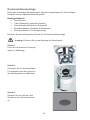
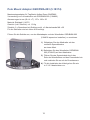
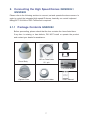
2.1.1 Lieferumfang GNSD882
Bitte prüfen Sie die Lieferung auf Vollständigkeit (siehe nachfolgende Liste). Bei eventuell
fehlenden und/oder beschädigten Teilen benachrichtigen Sie bitte umgehend Ihren
Händler, bevor Sie mit der Inbetriebnahme beginnen. Er wird alles Notwendige
veranlassen.
Gleitmittel
Schrauben
Dome / Kamera /
130-cm Daten Kabel
Gehäuse
22 - pin
2 x Ferritkern
Schutzhaube
Dichtgummi
8
Bedienungsanleitung
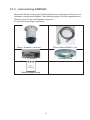
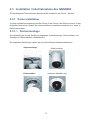
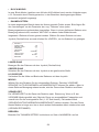
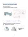
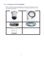
2.1.2 Lieferumfang GNSD682
Bitte prüfen Sie die Lieferung auf Vollständigkeit (siehe nachfolgende Liste). Bei evtl.
fehlenden und/oder beschädigten Teilen benachrichtigen Sie bitte umgehend Ihren
Händler, bevor Sie die Inbetriebnahme beginnen.
Er wird alles Notwendige veranlassen.
Dome / Kamera / Gehäuse
130-cm Daten Kabel22 - pin
2 x Ferritkern
Montageblende
Bedienungsanleitung
9
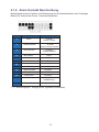
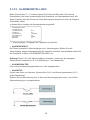
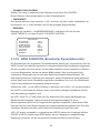
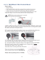
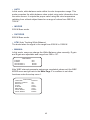
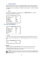
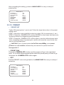
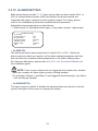
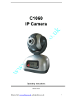
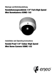
2.1.3
Schalterbeschreibung und Einstellung
Bevor Sie die Dome - Kamera mit anderen Geräten verbinden, ist es unerlässlich,
die Dome ID (Adresse) und das Kommunikations-/Steuerprotokoll zu überprüfen.
Die für die Einstellungen benötigten Schalter befinden sich im Unterteil der Dome Kamera (s. Abbildung).
A
Reserviert
B
wird nicht mehr benötigt
C
Dome ID (muss auf 001 stehen!)
D
Dome-Protokoll (muss auf 20 stehen!)
E
22-Pin Buchse
F
RJ-45 Buchse
10
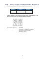
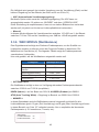
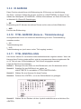
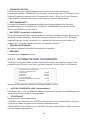
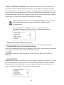
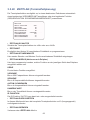
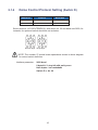
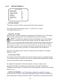
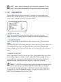
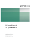
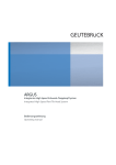
2.1.4
Dome - Kamera Fernsteuerprotokoll (Schalter D)
Einstellung der Schalter D für das benötigte Fernsteuerprotokoll
Switch Nr.
15
20
Protokoll
Baud Rate
JVC
9600
JVC/GEUTEBRÜCK
9600
Wählen Sie das JVC/GEUTEBRÜCK Protokoll mit der Schalterstellung 20 und
Baud Rate 9600, wie in der folgenden Abbildung dargestellt.
Zehner Einheit Einer Einheit
Schnittstellenparameter:
9600 Baud
8 Datenbits / 1 Stoppbit mit Parity even
Halb-Duplex / Kein Handshake
Schalter D -> Nr. 20
11
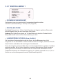
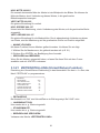
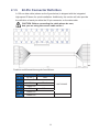
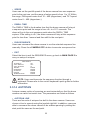
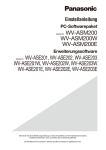
2.1.5
22-polige Steckerbelegung
Der Dome-Kamera ist ein 22-poliges Anschlusskabel mit 130 cm Länge zum
vereinfachten Anschluss beigelegt.
Die nachfolgenden Abbildungen und Tabellen zeigen die Pinbelegung des
22-poligen Steckers.
Achtung: VOR dem Anschluss unbedingt die Farben des
beiliegenden Kabels prüfen !
Funktion und Kennzeichnung der Anschlüsse:
Nr.
Funktion
1
AC24-1
2
Alarm Kontakt
3
AC24-2
4
Alarm Kontakt
5
FG
6
Alarm Kontakt
11-20
Alarm Kontakte
Kabel
Farbe
rot
schwarz
1007 20AWG
gelb
12
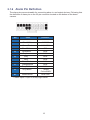
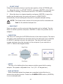
2.1.6 Alarm Kontakt Beschreibung
Nachfolgend wird die Funktion und Pinbelegung für die Alarmkontakte in der 22-poligen
Buchse im Unterteil der Dome - Kamera beschrieben
Kontakt
Farbe
2
Weiss
Definition
ALARM
NORMAL OFFEN
4
Schwarz/Weiss
ALARM
NORMAL GESCHLOSSEN
6
Grün/Schwarz
11
Blau/Weiss
12
Rot/Weiss
ALARM
GEMEINSAMER
ISOG
ALARM-1
13
Violett
ALARM-3
14
Grau
ALARM-2
15
Blau
ALARM-4
16
Weiss/Schwarz
ALARM-5
17
Orange/Schwarz
ALARM-6
18
Violett/Weiß
ALARM-7
19
Grau/Schwarz
20
Braun/Weiß
SCHALTER
FARBE/SW (*)
ALARM MASSE
(* = 7 Alarmeingänge + Eingang 8 als Tag/Nacht-Umschalter)
13
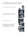
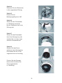
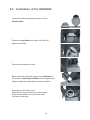
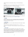
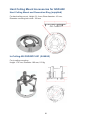
2.2 Installation / Inbetriebnahme des GNSD882
Die nachfolgende Dokumentation beschreibt Installation der Dome - Kamera.
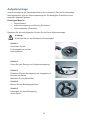
Auspacken und Bereitstellen der Dome - Kamerateile
Drehen und Abnehmen der oberen Gehäusekappe.
Evtl. vorher die Arretierschraube im Deckel lösen.
Entfernen der Schutzabdeckung.
Den Gummidichtring der unteren Domekuppel mit
dem beigelegten Gleitmittel bestreichen. Das
erleichtert die Montage der unteren Kuppel und
vermeidet Beschädigungen des Dichtringes.
14
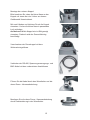
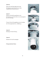
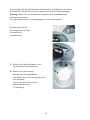
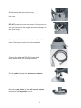
Montage der unteren Kuppel.
Bitte beachten Sie, dass die kleine Nase an der
Kuppel mit einem der vier Löcher am oberen
Gehäuseteil übereinstimmt.
Mit zwei Händen und leichtem Druck die Kuppel
einsetzen. Vorher die kleine Nase in passendes
Loch einhaken.
Auf keinen Fall die Kuppel wie im Bild gezeigt
einsetzen. Dadurch wird der Gummidichtring
beschädigt.
Verschrauben der Domekuppel mit dem
Wetterschutzgehäuse.
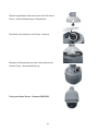
Verbinden der RS-485, Spannungsversorgungs- und
BNC-Kabel mit den vorbereiteten Anschlüssen
Führen Sie die Kabel durch den Wandhalter und die
obere Dome - Kameraabdeckung.
Montieren Sie die obere Dome - Kameraabdeckung
durch Rechtsdrehung in den Wandhalter.
15
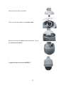
Mit der beigefügten Schraube fixieren Sie die obere
Dome - Kameraabdeckung im Wandhalter.
Einstecken des Kabels in die Dome - Kamera
Montieren (Rechtsdrehung) und Verschrauben der
oberen Dome - Kameraabdeckung.
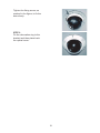
Fertig montierte Dome - Kamera GNSD882
16
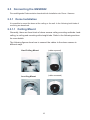
2.3 Installation / Inbetriebnahme des GNSD682
Die nachfolgende Dokumentation beschreibt die Installation der Dome - Kamera.
2.3.1 Dome Installation
Je nach Installationsumgebung wird der Dome an der Decke oder Wand montiert. In den
folgenden Abschnitten werden die unterschiedlichen Installationszubehöre und -arten im
Detail beschrieben.
2.3.1.1 Deckenmontage
Grundsätzlich gibt es drei Deckenmontagearten: Aufputzmontage, Deckeneinbau und
Montage mit Abstandshalter (Abstandsrohr)
Die folgenden Abbildungen zeigen die unterschiedlichen Kabelanschlussarten.
Aufputzmontage
(Kabel sichtbar)
(verdeckte Kabelführung)
Deckeneinbau
17
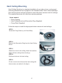
Aufputzmontage
Aufputzmontage ist die Standardinstallation für Innendome. Das hierfür notwendige
Montagezubehör liegt der Domeverpackung bei. Die benötigten Zubehöre sind im
folgenden Abschnitt gelistet.
Benötigtes Material:
•
Dome Kamera
•
Aufputzmontagering und Zierring (Enthalten)
•
Fixierungslasche (Enthalten)
Beachten Sie die nachfolgenden Schritte für die Dome-Aufputzmontage.
Achtung:
Entfernen Sie vor der Montage die Domekuppel!
Schritt 1
Schrauben Sie die
Fixierungslasche auf das
Domegehäuse.
Schritt 2
Lösen Sie den Zierring vom Aufputzmontagering.
Schritt 3
Platzieren Sie den Montagering am vorgesehenen
Platz an der Decke.
Markieren Sie die Bohrlöcher.
Schritt 4
Bohren Sie die Befestigungslöcher.
Schritt 5
Schrauben Sie den Montagering
an die Decke.
18
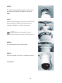
Schritt 6
Ziehen Sie das Datenkabel durch den
Montagering und stecken Sie es in den
vorgesehenen Domeanschluss.
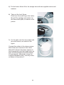
Schritt 7
Stecken Sie das Domegehäuse in den
Montagering und drehen Sie ihn im Uhrzeigersinn
bis zum Anschlag.
Fixieren Sie das Domegehäuse durch Anziehen
der Fixierungsschraube (s. Abbildung).
Schritt 8
Befestigen Sie den Zierring.
Schritt 9
Montieren Sie die Domekuppel.
Fertig montierter Dome
19
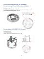
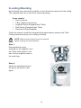
Deckeneinbaumontage
Das hierfür notwendige Montagezubehör liegt den Verpackungen bei. Die benötigten
Zubehöre sind im folgenden Abschnitt gelistet.
Benötigtes Material:
• Dome Kamera
• T-Bar (Einbausatz, optionales Zubehör)
• Fixierschraube (Enthalten im Einbausatz)
• Montageschablone (Enthalten im Einbausatz)
• Zierring (enthalten in Domeverpackung)
Beachten Sie die nachfolgenden Schritte für die Deckeneinbaumontage.
Achtung: Entfernen Sie vor der Montage die Domekuppel!
Schritt 1:
Lösen Sie die markierte Fixierungslasche (s. Abbildung)
Schritt 2:
Schrauben Sie mit der beigefügten
Fixierungsschraube die Lasche an
das Domegehäuse (s. Abbildung)
Schritt 3
Zeichnen Sie mit Hilfe der roten
Schablone den Deckenausschnitt
an.
20
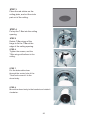
Schritt 4
Platzieren Sie den Einbausatz
in die vorgesehene Öffnung.
Schritt 5
Drehen Sie die
Befestigungsflügel um 180°
Schritt 6
Ziehen Sie die 3 Schrauben
(s. Abbildung) soweit an,
bis der Einbausatz fest in der
Öffnung sitzt.
Schritt 7
Ziehen Sie das Datenkabel
durch den Montagering und
stecken Sie es in den vorgesehenen Domeanschluss.
Schritt 8
Stecken Sie das Domegehäuse in den Montagering
und drehen Sie ihn im Uhrzeigersinn bis zum Anschlag.
Fixieren Sie das Domegehäuse durch Anziehen der
Fixierungsschraube
(s. Abbildung).
21
Befestigen Sie den Zierring.
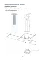
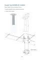
Deckenmontage mit Abstandsrohr
Das Abstandsrohr ist in 2 Längen erhältlich: 25 cm und 50 cm.
Benötigtes Material:
• Dome Kamera
• Abstandsrohr mit Zubehör (optional)
• Montageadapter und Zubehör (optional)
Beachten Sie die nachfolgenden Schritte für die Deckeneinbaumontage.
Achtung:
Entfernen Sie vor der Montage die Domekuppel!
1) Stellen Sie sicher, dass die Decke ausreichend tragfähig ist.
2) Beachten Sie: diese Montage ist nur mit verdeckter Kabelführung möglich!
22
3) Befestigen Sie das Abstandsrohr mit Schrauben und Dübeln an der Decke.
4) Ziehen Sie das Kabel durch das Abstandsrohr und den Montageadapter.
Achtung: Ziehen Sie vor Montage des Adapters die Gummiabdeckung
über das Abstandsrohr.
5) Verschrauben Sie den Montageadapter mit dem Abstandsrohr.
6) Schrauben Sie die
Fixierungslasche auf das
Domegehäuse,
s. Abbildungen
7) Stecken Sie das Datenkabel in den
vorgesehenen Domeanschluss.
8) Stecken Sie das Domegehäuse in den Montageadapter
und drehen Sie ihn im Uhrzeigersinn bis
zum Anschlag.
Fixieren Sie den Dome mit der
Sicherungsschraube,
(s. Abbildung)
23
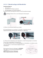
2.3.1.2 Wandmontage mit Wandhalter
Benötigtes Material:
• Dome Kamera
• Wandhalter und Zubehör (optional)
• Montageadapter und Zubehör (optional)
Beachten Sie die nachfolgenden Schritte für die Domeaufputzmontage.
Achtung: Entfernen Sie vor der Montage die Domekuppel!
1) Offene und verdeckte Kabelführung möglich.
2) Um das Eindringen von Insekten zu vermeiden, verschließen Sie die
Kabeldurchführung mit beiliegendem Schwamm (s. Abbildung).
3) Ziehen Sie das Kabel durch den Wandhalter und den Montageadapter und stecken
Sie es in den vorgesehenen Domeanschluss.
4) Befestigen Sie den Dome und Montageadapter am Wandhalter und verfahren weiter
wie unter Schritt 6 -9 der Deckenmontageanleitung mit
Abstandsrohr.
Bitte beachten Sie bei der Montage des GNSD682,
dass dieser nur mit dem Domemontageadapter
GSD/BDA-001 montiert werden kann.
Bitte separat bestellen (5.04866)
24
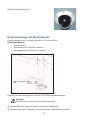
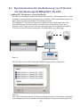
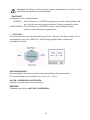
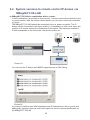
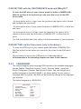
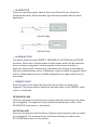
2.4 Systemvarianten für die Bedienung von IP-Domen
mit dem Bediengerät MBeg/GCT-3X-LAN
a) MBeg/GCT-3X-LAN an re_porter/GeViScope:
Bei dieser Konstellation besteht die Möglichkeit maximal 1 Bediengerät direkt an das
jeweilige re_porter/GeViScope System anzuschließen. Mit diesem Bediengerät kann
dann immer nur das verbundene Gerät bedient werden.
Das MBeg/GCT-3X-LAN wird über einen Switch mit dem Gerät verbunden. Die
anzuschließenden IP-Dome werden ebenfalls über diesen Switch (oder auch
mehrere, wenn nötig) an den re_porter angeschlossen. Die Anzahl der möglichen
IP-Dome ist von der Aufzeichnungsrate, der Bildqualität, usw. abhängig.
1
n
Abb. 01
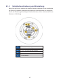
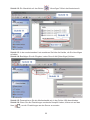
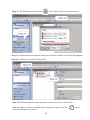
Die IP-Dome sind im GSC-Setup als CAM2IP-Signalquellen zu erkennen.
Abb. 02
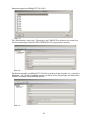
Ihren MAC-Adressen werden im Setup die entsprechenden IP-Adressen zugeordnet
und entsprechend ihrer Auswahl als lokale Eingänge konfiguriert (notwendig für die
25
Kameraeingabe am MBeg/GCT-3X-LAN ).
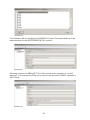
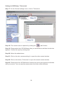
Abb. 03
Die „Schnittstelle“ wird unter „Telecontrol“ als CAM2IP-Port erkannt und muss hier
für das notwendige Protokoll (GEUTEBRÜCK/JVC) parametriert werden.
Abb. 04
Die Kameraanwahl per MBeg/GCT-3X-LAN ist analog zu der Anwahl von „normalen“
Kameras – die lokalen Eingänge werden im Setup in der Reihenfolge der aktivierten
CAM2IP-Kameras entsprechend gesetzt.
Abb. 05
26
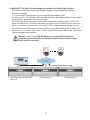
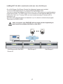
b) MBeg/GCT-3X-LAN in Verbindung mit maximal drei GeViScope Geräten:
Auf einem GeViScope Gerät (GeViScope Dongle) sind grundsätzlich folgende
Lizenzen enthalten:
1 x Licence/GSC/OpKeyb plus 3 x Licence/GSC/SysIntMSC+GSC.
Auf dem „ersten“ GeViScope (GSC) wird die Software GeViSoft installiert. Hier werden
dann die oben genannten Lizenzen benötigt.
Die GSCs werden im Netzwerk miteinander verbunden und dem „ersten“ GSC wird
dann das MBeg/GCT-3X-LAN zugeordnet. An jedem der drei GSCs können jetzt, wie
schon in Variante a) beschrieben, so viele IP- Dome angeschlossen werden, wie es
die Aufzeichnungs-Parameter zulassen. Aktivierung und Einstellung der IP-Dome ist
identisch zu a). In jedem GSC, dem 1 Dome zugeordnet werden soll, muss Telecontrol
aktiviert/programmiert werden!
Hinweis: um z. B. nur EIN GeViScope mi t einem Bediengerät zu
verbinden, muss ebenfalls die Software GeViSoft auf dem jeweiligen
Gerät installiert werden!
1
GeViScope mit GeViSoft
GeViScope 2
Abb. 06
27
n
GeViScope 3
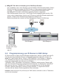
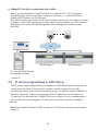
c) MBeg/GCT-3X-LAN in Verbindung mit n GeViScope-Geräten:
Hier empfiehlt es sich, einen Rechner mit der Software GeViSoft auszustatten. Dieser
Rechner benötigt dann einen GeViSoft-Dongle mit einer entsprechenden Anzahl an
Lizenzen: 1 x Licence/GSC/OpKeyb plus n x Licence/GSC/SysIntMSC+GSC.
Das MBeg/GCT-3X-LAN wird diesem separaten Rechner zugeordnet.
Über Netzwerkkabel können nun n GeViScope Geräte angeschlossen werden. Wie
schon unter b) beschrieben, können nun IP-Dome an jedes GeViScope angebunden
werden, soweit es die Aufzeichnungs-Parameter zulassen. Die
Bedienung erfolgt dann zentral von dem Management-System GeViSoft aus.
1
GeViScope 1
n
GeViScope n
PC mit GeViSoftDongle und entspr.
Lizenzen
Abb. 07
2.5
Programmierung von IP-Domen in GSC-Setup
IP-Dome werden im Setup des GeViScopes eingebunden / aktiviert. Hierbei sollte die IDAdresse des einzustellenden Domes und dessen Protokoll-Nr. überprüft werden. ID
muss 001, das Protokoll die Nr. 20 sein ( GEUTEBRÜCK/ JVC-Protokoll, s. Abschnitt
2.2). Nachdem die Dome an einen Switch angeschlossen und ihre Spannungsversorgungen eingeschaltet sind, können nun im Menü
"Hardware" durch "Hinzufügen" die erkannten "CAM2IPs" addiert werden. Danach gibt
man den einzelnen Domen eine entsprechende IP-Adresse. Im Menüpunkt "Telecontrol"
fügt man nun den sog. "CAM2IP-Port" hinzu und konfiguriert ihn auf das benötigte
Protokoll. Danach muss allen IP-Domen die Bus-Adresse "1" zugeordnet werden.
Jetzt sind alle an diesem Gerät eingestellten Dome steuerbar.
Hinweis: Sollte die Dome-ID (im Dome) auf "000" stehen, befindet er sich im Testmodus
und ist nicht steuerbar!
28
2.5.1 Programmierung von VIPCAM-Domen in GSC-Setup
Im GSCSetup werden die im LAN erreichbaren VIPCam-Dome automatisch
gesucht. Sie erscheinen in der Hardware Module List.
Es sind folgende Schritte erforderlich:
• Zuordnung einer IP-Adresse und eines Funktionspaketes (Function package).
• Hinzufügen und Konfiguration der Medienkanäle (Media channels).
• Hinzufügen des Netzwerk-Ports in Telecontrol
• Überprüfung der Domefunktionen in Telecontrol
Danach stehen die angeschlossenen VIPCAM-Dome im GeViScope / re_porter zur
Verfügung.
Unbedingt beachten:
Die einwandfreie Funktion der VIPCAM-Dome ist erst ab der GeViScope/re_porter
Softwareversion 5.0.790.48 gewährleistet. Update-Download unter www.geutebrueck.de
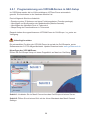
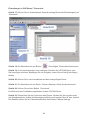
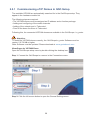
Hinzufügen der VIPCAM-Dome
Öffnen Sie GeViScope Setup mit einem Doppelklick auf das Icon GscSetup .
Schritt 1: Verbinden Sie im Menü Connections das GeViScope mit einem Server.
Schritt 2: Öffnen Sie mit einem Klick mit der linken Maustaste das Menü General
Settings.
29
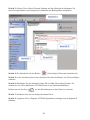
Schritt 3: Klicken Sie im Menü General Settings auf den Menüpunkt Hardware. Es
wird die angemeldete und konfigurierte Hardware des Basisgerätes aufgelistet.
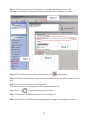
Schritt 4: Ein Mausklick auf den Button
[Hinzufügen] öffnet das Kontextmenü.
Schritt 5: In der erscheinenden Liste markieren Sie bitte die Module, die Sie hinzufügen
möchten.
Schritt 6: Bestätigen Sie die Auswahl indem Sie auf Add [Hinzufügen] klicken. Es
erscheinen nun die zusätzlichen VIPCAM-Dome in der Hardwaremodulliste.
Klicken sie auf das Ikon
, um die Einstellungen an den Server zu senden.
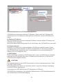
Schritt 7: Markieren Sie den zu konfigurierenden Dome.
Schritt 8: Vergeben Sie im Register VIPCAM Speeddome settings eine verfügbare IP
Adresse.
30
Installationshinweise zur IP-Adresskonfiguration:
VIPCAM-Dome verwenden statische IP Adressen. Daher muss die IP Adresse des
GeViScopes eine IP Adresse aus dem gleichen IP-Subnetz, wie die VIPCAM-Dome
haben.
a) Statische IP Adresse
Dem GeViScope wird eine feste statische IP-Adresse mit dem selben IP-Subnetz der
VIPCAM- Dome vergeben.
Dies ist die bevorzugte Konfiguration für ein GeViScope, das VIPCAM-Dome verwendet.
b) 2 Netzwerkkarten
Alternativ zu a) kann eine 2. Netzwerkkarte im GeViScope installiert werden. Diese
ermöglicht einen dualen Betrieb von DHCP und statischer IP. Die Kommunikation mit
den VIPCAM-Domen erfolgt über die 2. Netzwerkkarte, die mit einer statischen IP
Adresse wie in a) konfiguriert wird.
c) DHCP Modus
Einem GeViScope, welches im DHCP Modus läuft, muss vom DHCP Server entweder
eine stati- sche IP-Adresse oder eine IP-Adresse aus dem gleichen IP-Subnetz der
VIPCAM-Dome vergeben werden.
ACHTUNG:
Ein Verbindungsverlust zum DHCP Server kann zu einem Verbindungsverlust zu den
VIPCAM- Domen führen!
Dieser Betriebsmodus sollte nur verwendet werden, wenn eine ständige Verbindung
zum DHCP Server gesichert ist!
Verwendung von VIPCAM-Domen in IP Netzwerken mit Routern:
VIPCAM-Dome verwenden in der aktuellen Softwareversion UDP Broadcastpakete für
die Lokalisierung und Statusübertragung.
31
Eventuell vorhandene Router müssen so konfiguriert werden, dass >alle< TCP und UDP
Pakete mit den Portnummern
12010 bis 12013
in beide Richtungen weitergeleitet werden.
Wenn die VIPCAM-Dome nicht lokalisiert werden können, sind die Router für den
VIPCAM-Dome Betrieb nicht korrekt konfiguriert.
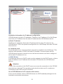
Schritt 9: Überprüfen Sie im Register Function packages [Funktionspakete] ob das
geeignete
Funktionspaket (Mpeg4CCTV) eingestellt ist.
Wenn mehrere Funktionspakete vorhanden sind, können Sie durch anklicken der
Funktion Latest [Neustes] bestimmen, dass immer die neueste Version geladen wird.
Schritt 10: Wenn Sie alle Einstellungen nochmals überprüft haben, klicken sie auf das
Ikon
, um die Einstellungen an den Server zu senden.
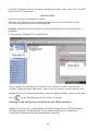
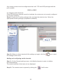
Hinzufügen und Konfiguration der Medienkanäle (Media channels)
Schritt 11: Klicken Sie im Auswahlmenü General settings [Generelle Einstellungen]
auf Media channels [Medienkanäle], um die Medieneinstellung zu initialisieren.
Es werden die Medienkanäle des Basisgerätes angezeigt.
32
“Hinzufügen” öffnet das Kontextmenü.
Schritt 12: Ein Mausklick auf den Button
Schritt 13: In der erscheinenden Liste markieren Sie bitte die Kanäle, die Sie hinzufügen
möchten.
Schritt 14: Bestätigen Sie die Eingabe, indem Sie auf Add [Hinzufügen] klicken.
Schritt 15: Parametrieren Sie die Medienkanäle wie in der Online-Hilfe beschrieben.
Schritt 16: Wenn Sie alle Einstellungen nochmals überprüft haben, klicken sie auf das
Ikon
, um die Einstellungen an den Server zu senden.
33
Einstellungen in GSCSetup / Telecontrol
Schritt 17: Klicken Sie im Auswahlmenü General settings [Generelle Einstellungen] auf
Telecontrol.
Schritt 18: Ein Mausklick auf den Button
“Hinzufügen” öffnet das Kontextmenü.
Schritt 19: In der erscheinenden Liste markieren Sie bitte den VIPCAM-Dome, den
Sie hinzufügen möchten. Bestätigen Sie die Eingabe, indem Sie auf Add [Hinzufügen]
klicken.
Schritt 20: Klicken Sie in der Auswahlliste auf den hinzugefügten Dome.
Schritt 21: Ein Mausklick auf den Reiter „Camera Settings“ öffnet das Kontextmenü.
Schritt 22: Klicken Sie auf den Button „Telecontrol“.
Es öffnet sich das Fernbedienungsfenster für den VIPCAM-Dome.
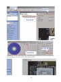
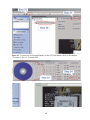
Schritt 23: Überprüfen Sie die Funktionen des Domes. Klicken Sie den Joystick oder
die Schieberegler an, halten die Maustaste gedrückt und bewegen Sie z.B. den Joystick.
Die Reaktion sehen Sie im Videokontrollfenster des Reiters Camera Settings.
34
Schritt 24: Um das OSD-Menü des VIPCAM-Domes sichtbar zu machen, klicken Sie
auf den Button „Function V On“ oder „Camera ON“.
35
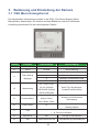
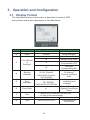
3. Bedienung und Einstellung der Kamera
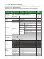
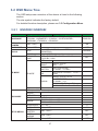
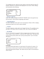
3.1 OSD Menü Anzeigeformat
Die dargestellten Informationen werden in der OSD- (On-Screen-Display) MenüBaumstruktur beschrieben. Die Position auf dem Bildschirm und die Funktionsbeschreibung entnehmen Sie der nachfolgenden Tabelle.
Position
Funktion
OSD Anzeige
Beschreibung
ohne Funktion
nicht enthalten
ALARM
Alarm Meldung
A
Auto-Fokus-Modus
Fokus Modi &
M
Manueller Fokus-Modus
Backlight
X
Backlight Compensation AUS
B
Backlight Compensation AN
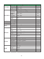
1
2
3
Alarm
XX...(Dome-Typ)
4
Startmeldung
ID: 001 (Default)
DSCP/9600 (Default)
Dome-Typ, Bus-Adresse,
Protokoll und Baud Rate
INITIALISIERUNG
Schwenken Fehler
5
Fehlermeldung
Neigen Fehler
Anzeige von Fehlern beim
Startvorgang
Kam.-Modul Fehler
6
Zoom-Faktor
7
Titel
Momentaner Zoom-Faktor
x1
(Optisch /Digital)
• maximal 20 Zeichen pro Titel
• 16 Titel sind verfügbar
8
Kamera ID
001
Anzeige d. Bus-Adresse
9
Zeit
XXXX/XX/XX XX:XX
Jahr/Monat/Tag Stunde:Minute
36
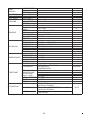
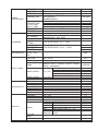
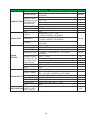
3.2 OSD-Menü Baumstruktur
Im nachfolgenden Abschnitt wird die OSD-Menü-Struktur und das Setup beschrieben.
Der Stern steht für "Werkeinstellung".
Die ausführliche Funktionsbeschreibung folgt in Abschnitt 4.3 Menüeinstellungen.
Begriff
SPRACHE
STANDARD
KAMERA
BEL. KOMP.
FOKUS
AE MODUS
WBC MODUS
EINST.
MENUE 1
Ebene 1
Ebene 3
<ENGLISCH>, <VEREINF. CHINES.>, <FRANZ.>, <DEUTSCH>,
<ITAL>, <JAPANISCH>, <POLNISCH>, <PORTUG.>,
<RUSSISCH>, <SPANISCH>, <TUERKISCH>
Werkeinst.
ENGLISCH
<AN>, <AUS>
AN
<AN>, <AUS>
AUS
AF MODUS: <NORMAL>, <INTERVALL>,
<ZOOM TRIG>
MANUELL
FOKUS GESCHW. <01>~<08>
<AUS>, BELICHTUNGSWERT: <-10.5dB> ~
BELICHTUNGSKOMPENSATION <+10.5dB>
AUTO
HELLIGKEITSWERT
HELLIGKEIT <00>~<31>
SHUTTER GESCHW.
SHUTTER
<1/10000>~<1>SEK.
BLENDENZAHL <ZU>, <F1.6>
~
BLENDE
AE MODUS
<F28>
HELL. WERT: AUTO
SHUTTER GESCHW.
<1/10000>~<1>SEK.
MANUELL
BLENDE <F1.6>~<F28>
VERST. <-3>dB ~ <28>dB
JA
BEENDEN
AUTO (Auto White Balance)
INNEN
AUSSEN
ATW (Auto-Tracking White)
R VERST. <000>~<127>
MANUELL
B VERST. <000>~<127>
ZOOM GESCHW. <1>~<8>
DIGITAL ZOOM
<AN>, <AUS>
SLOW SHUTTER <AN>, <AUS>
BILDUMKEHR
<AN>, <AUS>
STANDBILD
<AN>, <AUS>
KANTENANH.
<01>~<16>
AUTO
STABILIZER
STABLE ZOOM
EINST.
MENUE 2
Ebene 2
BEENDEN
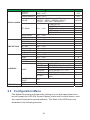
FLIP
WINKEL-EINST.
PROPORT.
ZOOM
AUTO KALIBR.
PASSWORT
<ON>. <OFF>
<ON>. <OFF>
JA
NORMAL
AUS
8
AN
AUS
AUS
AUS
11
OFF
OFF
<AUS>, <M.E>, <BILD>
MIN. WINKEL <-10°~+10°>
MAX. WINKEL <080° ~ 100°>
AUS
0
90
<AN>, <AUS>
AUS
<AN>, <AUS>
<AN>, <AUS>
AUS
AUS
37
EINST.
MENUE 2
SYSTEM RESET
SCAN MODE
BEENDEN
ID ANZEIGE
<AN>, <AUS>
TITEL ANZEIGE <AN>, <AUS>
TITEL EINST.
<01> ~<16>
VORG. SETZEN
VORGABE
VORG. START
BEENDEN
SEQUENZ LINIE
SEQUENZ
PUNKT
VORGABE.
SEQUENZ
GESCHW.
VERWEILZEIT
SEQ. START
BEENDEN
AUTOS. LINIE
STARTPUNKT
ENDPUNKT
AUTOSCHW.
RICHTUNG
GESCHW.
AUTOS. START
BEENDEN
KAM.-F. LINIE
AUFZ. START
KAMERAFAHRT AUFZ. ENDE
KAM.-F. START
BEENDEN
STARTFUNKTION
STARTEINST.
IR FUNKTION
JA
<I>, <P>
JA
I
AN
AUS
01
<001>~<256>
<001>~<256>
JA
EINGABE
EINGABE
EINGABE
<1> ~<8>
1
<01> ~<32>
01
<001>~<255>, <ENDE>
<01>~<15>
<000>~<127>SEK.
EINGABE
001
01
000
JA
<1> ~<4>
<FINDEN>, <SPEICHERN>
<FINDEN>, <SPEICHERN>
<RECHTS>, <LINKS>
<01>~<04>
EINGABE
1
RECHTS
01
JA
<1> ~<4>
EINGABE
EINGABE
EINGABE
1
JA
<AN>, <AUS>
<VORGABE>, <SEQUENZ>,
<AUTOSCHW.>,
MODUSWAHL
<KAMERAFAHRT>
<001>~<256>
VORG. PUNKT
SEQUENZ LINIE <1>~<8>
AUTOS. LINIE
<1> ~<4>
KAM.-F. LINIE
<1> ~<4>
RUECKKEHRZEIT <1>~<128>MIN.
START
EINGABE
JA
BEENDEN
<AUTO>
GRENZWERT <01> ~ <29>
Light Source IR/Visible
<MANUELL>
<AN>, <AUS> GRENZWERT <01> ~ <29>
Light Source IR/Visible
(Alarm-Pin
8: offen = Farbmodus; geschl.
<KABEL>
= SW- Modus)
38
AUS
VORGABE
001
1
1
1
1
AUTO
ALARM PIN
ALARM SCH.
ALARM TYP
ALARM –
EINSTELLUNG
ALARMAKTION
VORG. PUNKT
SEQUENZ LINIE
AUTOS. LINIE
KAM.-F. LINIE
VERWEILZEIT
BEENDEN
ERK. SCHALTER
ERK. MODUS
ALARMERK.
WDR FUNKTION
BLOCK MODUS
RAHMEN
SETZEN
RAHMEN DEAKT.
GRENZWERT
BEENDEN
<AN>, <AUS>
<AUTO>. <RF>.
<DC>
PRIVACY
SCHALTER
TRANSPARENZ
FARBE
PRIVACY MASK
MASKE SETZEN
ZEITEINSTELLG.
ZEITPLAN
BEENDEN OSD
MASKE LOESCH
BEENDEN
ZEITANZEIGE
JAHR EINST.
MONAT EINST.
TAG EINST.
STUNDE EINST.
MINUTE EINST.
BEENDEN + SP.
ZEITSCHALTER
ZEITPUNKT
STUNDE
MINUTE
MODUS
ZEITPLAN
RESET
BEENDEN
JA
1
<1> ~<8>
AUS
<AN>, <AUS>
<NO> (Normal Offen), <NC> (Normal Geschl.)
N.C.
<VORGABE>, <SEQUENZ>,
<AUTOSCHW.>,
VORGABE
<KAMERAFAHRT>
001
<001>~<256>
1
<1> ~<8>
1
<1> ~ <4>
1
<1> ~ <4>
<001>~<127>sec, <IMMER>
IMMER
JA
<AN>, <AUS>
AN: <INT FOKUS>, <FIX FOKUS>, <FIX AE>,
<BEWEGUNG>; AUS: KEIN
KEIN; BEWEGUNG: <AN>, <AUS>
AUS
KEIN; BEWEGUNG: <01> ~ <04>
KEIN; BEWEGUNG: <01> ~ <04>
KEIN; BEWEGUNG: <001> ~ <255>
JA
AUS
<AN>, <AUS>
AUS
<AN>, <AUS>
<SCHWARZ>, <HELLGRAU>, <DUNKELGRAU>,
<WEISS>, <ROT>, <GRUEN>, <BLAU>, <CYAN>,
<GELB>, <MAGENTA>
H MITTE: L/R
V MITTE: U/O
<01>~<24> H GROESSE <000> ~ <080>
V GROESSE <000> ~ <060>
BEENDEN + SPEICHERN
<01>~<24>
JA
<AN>, <AUS>
<00> ~ <99>
<01>~<12>
<00>~<31>
<00> ~ <23>
<00> ~ <59>
AUS
<AN> <AUS>
<01> ~<32>
<00> ~ <23>
<00> ~ <59>
KEIN
KEINE FUNKTION
VORGABE VORGABEPUNKT <001> <256>
SEQUENZ
SEQUENZ LINE <1>~<8>
AUTOSCH AUTOSCHW. LINIE <1> ~ <4>
KAM.KAM.-FAHRT LINIE <1> ~ <4>
IR
IR FUNKTION <AUTO>, <AN>,
FUNKTION <AUS>
JA
JA
SCHWARZ
01
00
00
3.3 Einstellungsmenü
Die verfügbaren Funktionen und Parametereinstellungen Ihrer Hochgeschwindigkeits Dome - Kamera werden mit einem Bediengerät über das OSD (On Screen Display)Menü konfiguriert.
Die einzelnen Elemente des OSD-Menüs werden in den folgenden Abschnitten
beschrieben.
HAUPTSEITE 1
SPRACHE
STANDARD KAMERA
GEGENLICHT
FOKUS
AE MODUS
WBC MODUS
EINSTELLMENÜ 1
EINSTELLMENÜ 2
HAUPTSEITE 2
ID ANZEIGE
TITELANZEIGE
TITEL EINSTELLUNG
VORGABE
SEQUENZ
AUTOM. SCHWENKEN
KAMERAFAHRT
STARTEINSTELLUNG
DEUTSCH
AN
AUS
AUTO
AUTO
AUTO
ENTER
ENTER
AN
AUS
01
ENTER
ENTER
ENTER
ENTER
ENTER
OSD-EINSTELLUNG mit dem GEUTEBRÜCK Bediengerät MBeg/GCT
Um in das OSD-Menü Ihrer Kamera zu gelangen, drücken Sie die <KAMERA AN>
Taste Ihres MBeg/GCT.
Bewegen Sie mit dem Joystick Ihres Bediengerätes den OSD-Cursor zum
gewählten OSD - Menüpunkt.
HAUPTSEITE 3
IR FUNKTION
ALARMEINSTELLUNG
ALARM DETEKTION
PRIVACY MASK
EINSTELLUNG ZEIT
ZEITPLAN
BEENDEN OSD
- Bei Menüpunkten mit einem
AUTO
ENTER
AUS
ENTER
ENTER
ENTER
JA
Zeichen, drücken Sie den Joystick in Richtung
rechts oder links, um den Menüpunkt auszuwählen und zu konfigurieren.
- Bei Menüpunkten mit einem
Zeichen, drücken Sie die <KAMERA AUS>
Taste des Bediengerätes, um in das dazu gehörige Untermenü zu gelangen.
- Bei Menüpunkten mit einem
Zeichen, drücken Sie den Joystick in Richtung recht
oder links zur Auswahl einer Funktion und danach die <KAMERA AUS> Taste, um in
das dazu gehörige Untermenü zu gelangen.
Weitere Einzelheiten zur Bedienung finden Sie in der Dokumentation Ihres Bediengerätes.
40
OSD-EINSTELLUNG via GscTelecontrol (nur im GscSetup möglich!)
Um das OSD-Menü des Domes aufzurufen, drücken Sie den <CAMERA ON>-Button.
Bewegen Sie mit dem Joystick den OSD-Cursor zum gewählten OSD - Menüpunkt.
- Bei Menüpunkten mit einem
Zeichen, bewegen Sie den Joystick nach links oder
rechts, um die Funktion dieses Menüpunktes auszuwählen.
- Bei Menüpunkten mit einem
Zeichen, drücken Sie den <CAMERA OFF>- Button
(= <ENTER>) um in das dazu gehörige Untermenü zu gelangen.
- Bei Menüpunkten mit einem
Zeichen, verfahren Sie wie vor beschrieben.
Alle folgenden Bewegungen im OSD-Menü werden so ausgeführt!
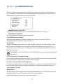
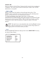
3.3.1 LANDESSPRACHE
Die Kamera unterstützt die OSD-Funktionen in verschiedenen Landessprachen.
Es sind aktuell folgende Landessprachen verfügbar: Englisch (Werkeinstellung),
Chinesisch, Französisch, Deutsch, Italienisch, Japanisch, Polnisch, Portugiesisch,
Russisch, Türkisch und Spanisch.
Wenn Sie eine Sprache mit den Joystick (Rechts/Links) ausgewählt haben,
wechselt das OSD-Menü automatisch in die gewählte Sprache.
3.3.2 STANDARD (Werkeinstellung) KAMERA
Wählen Sie "AN" um die Kamera auf die Werkeinstellungen zurückzusetzen.
Wenn Sie Änderungen vornehmen wollen, wählen Sie "AUS".
Werden Änderungen vorgenommen, geht diese Anzeige automatisch auf "AUS".
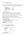
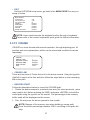
3.3.3 GEGENLICHT (Gegenlichtkompensation)
Sind sehr helle Flächen hinter einem Objekt in Bildmitte, so wird dieses zu dunkel
dargestellt. In solchen Fällen "AN" wählen. Das Objekt im Vordergrund wird dann heller
dargestellt. Das Kompensationslevel ist im Bereich 0 bis 30 einstellbar.
BLC LEVEL
00
41
3.3.4 FOKUS
Für die optische Fokussierung kann zwischen dem „Manuellen Fokus Modus" und dem
„Autom. Fokus Modus" gewählt werden.
• AUTOMATISCH
Die optimale Schärfe wird durch einen internen Regelkreis ständig optimiert.
Hier gibt es drei Modi für unterschiedliche Bedingungen:
Normaler AF-Modus (Autofokus ): der Dome regelt den Fokus ständig nach.
Zoom Trigger Modus: wenn die Brennweite verändert wird, regeIt der Dome den Fokus
nach Beenden des Zooms nach (Werkeinstellung ist 5 Sek.).
Intervall AF-Modus: wenn die Brennweite in bestimmten Intervallen verändert wird,
regeIt der Dome den Fokus in einstellbarer Zeit nach (Werkeinstellung 5 Sek.).
• MANUELL
Der Bediener kann mit den Potis <FocusNear(Nah)/Far(Fern)> auf der Oberfläche
die Bildschärfe verändern; die Geschwindigkeit ist variabel von 1 bis 8.
FOKUS GESCHWINDIGKEIT
1-8
Beachte! Der AF-Modus wird nach jedem Neustart wieder aufgenommen.
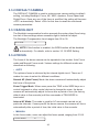
3.3.5 AE MODUS (Belichtungsregelung)
Hier kann die Funktion der Belichtungsregelung gewählt werden. Ein manueller
Wert reicht von -10,5 dB bis +10,5 dB. Mit "AUS" sind folgende Punkte erreichbar:
• AUTOMATISCH (wird dieser Modus deaktiviert, schaltet der IRC-Filter NICHT
mehr automatisch um!)
Bei dieser Einstellung beeinflusst die Kamera die Regelkreise VERSCHLUSS, BLENDE,
HELLIGKEIT + AGC selbsttätig.
Ziel ist es, immer den vollen Videoausgangspegel zu erreichen. Diese Einstellung ist die
beste, wenn durch die Anwendung keine anderen Prioritäten gesetzt werden.
• VERSCHLUSS (Shutter, Belichtungszeit)
Hier wirkt zuerst die Belichtungszeitregelung. Ist diese an ihrer Grenze, greifen
„BLENDE" und dann „AGC" ein.
• BLENDE (Iris)
Hier wirkt zuerst die Blendenregelung. Ist diese an ihrer Grenze, greifen „VERSCHLUSS"
und dann "AGC" ein.
• HELLIGKEIT (Brightness)
Der interne Rechenalgorithmus beeinflusst hier sowohl Blende als auch AGC.
42
Die Helligkeit wird geregeIt: bei dunkler Umgebung von der Verstärkung (Gain) und bei
hellerer Umgebung von der Blende (der Wert reicht von 00 bis 31).
• AGC (Automatische Verstärkungsregelung)
Bei dieser Option wirkt zuerst die Verstärkungsregelung. Die AGC kann nur
ausgeschaltet werden. Es wirken nur „BLENDE" und dann „VERSCHLUSS".
Diese Einstellung ist empfehlenswert, wenn ein zu starkes Bildrauschen verhindert
werden soll (ist jedoch mit Verlust an Lichtempfindlichkeit verbunden).
• Manuell
In diesem Modus können die Verschlusszeiten zwischen 1/10.000 und 1, die Blende
zwischen F1.6 bis F28 und die Verstärkung von -3dB bis +28 dB eingestellt werden.
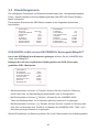
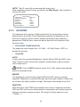
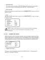
3.3.6 WBC MODUS (Weißbalance)
Eine Digitalkamera benötigt eine Referenz-Farbtemperatur, um die Qualität von
Lichtquellen messen zu können und in der Folge die Farben zu berechnen. Die
Maßeinheit ist Grad Kelvin (K). Die folgende Tabelle zeigt die Farbtemperaturen
verschiedener Lichtquellen.
Hier wird gewählt, wie die Weißbalance eingestellt werden soll.
Lichtquelle
Farbtemperatur in K
Bedeckter Himmel
6.000 - 8.000
Mittagssonne/klarer
Himmel
6.500
Wohnungsbeleuchtung
2.500 - 3.000
75 Watt Glühlampe
Kerzenflamme
2.820
1.200-1.500
• AUTOMATISCH
Die Weißbalance erfolgt in dem zur Verfügung stehenden Farbtemperaturbereich
zwischen 3.000 K und 7.500 K (empfohlen).
INNEN (Indoor) > auf der Basis von 3200 K; AUSSEN (Outdoor) mit 5860 K.
ATW (Auto Tracking White) > Regelung im Bereich von 2000 K bis 10000 K.
• MANUELL
In dieser Betriebsart wird die Weißbalance manuell eingestellt und bleibt für alle
Lichtverhältnisse gleich. R-gain (Rot-Verstärkung) und B-gain (Blau-Verstärkung) können
in einem Bereich von 0 bis 127 verändert werden. Nur zu empfehlen bei konstanter
Farbtemperatur (z. B. Innenräume, Tunnels, etc.).
WBC MENÜ
R VERSTÄRKUNG
B VERSTÄRKUNG
50
50
43
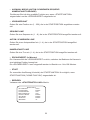
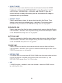
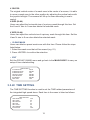
3.3.7 EINSTELLMENÜ 1
EINSTELLMENU 1
ZOOMGESCHW.
DIGITALER ZOOM
LANGSAME VERSCHLUSSZEIT
BILDUMKEHRUNG
STANDBILD
BLENDENÖFFNUNG
STABILIZER
STABLE ZOOM
BEENDEN
8
AN
AUS
AUS
AUS
AUTO
OFF
OFF
JA
• ZOOMGESCHWINDIGKEIT
Der Bediener kann eine gewünschte Zoomgeschwindigkeit einstellen
zwischen 8 (Werkeinstellung = schnell) und 1 (langsam).
• DIGITALER ZOOM
Der Digital Zoom ist max. 12-fach. Nach Erreichen der längsten optischen Brennweite
läuft der digitale Zoom bis zum maximalen Wert weiter.
Achtung! Der Digital Zoom nimmt ein Teil des Bildes und dehnt ihn. Deshalb ist die
Bildqualität hierbei reduziert! Die Werkeinstellung ist <AN>.
• LANGZEITBELICHTUNG (slow shutter)
Die Verschluss-Geschwindigkeit regelt die Dauer, die der Bildsensor dem Licht
ausgesetzt ist. Um klare Bilder in einem dunklen Umfeld zu erzeugen, aktivieren Sie bitte
diese Funktion und wählen Sie eine längere Verschlusszeit.
Durch die Integration mehrerer Bilder kann die Lichtempfindlichkeit im gleichen Verhältnis
gesteigert werden. Bei zu hoher Integration erscheinen Bewegungen jedoch verwischt
(Mann geht durch die Wand). Der Dome stellt den Slow Shutter automatisch auf die
Helligkeitsverhältnisse der Installationsumgebung ein. Objekte unterhalb von ca. 0,2 Lux
können so noch sichtbar gemacht werden (Werkeinstellung=AUS) .
44
• BILDUMKEHRUNG (z. B. für Demozwecke > Dome STEHT)
Wählen Sie die Option <AN> wenn Sie das dargestellte Bild horizontal und vertikal
spiegeln möchten (siehe Darstellungen unten). Privacy Masking wird in diesem Fall
deaktiviert! Die Werkeinstellung ist <AUS>.
BILDUMKEHRUNG (AUS)
BILDUMKEHRUNG (AN)
• STANDBILD (Freeze)
Hier kann während der Anfahrt zu einer Festposition das vorher gezeigte Bild
"eingefroren" werden. Das Standbild verschwindet erst, wenn die gewünschte
Festposition erreicht ist.
• KANTENANHEBUNG (Aperture)
Eine Verbesserung des Schärfeneindrucks kann durch Variation der elektronischen
Apertur erreicht werden. Achtung! Zu viel Apertur wirkt plastisch und verursacht stärkeres
Rauschen im Bild. Hier sind Einstellwerte von <01> bis <16> möglich, wobei <01>
gleichbedeutend ist mit "keine Anhebung" (Werkeinstellung ist <11>).
• BILDSTABILISIERUNG
Der Anwender kann die Bildstabilisierungsfunktion einschalten <AN>, um ein Zittern des
Bildes zu reduzieren, welches durch Erschütterungen oder andere Umstände hervor
gerufen werden kann. Somit ist es möglich, eine fast 90%ige Unterdrückung des Zitterns
zu erreichen bei Frequenzen um die 10 Hz.
Dabei wird der Bildausschnitt und die Auflösung verändert, während die Empfindlichkeit
beibehalten wird, weil diese Funktion auch den Digital-Zoom mit einschließt. Die
Werkeinstellung ist <AUS>.
• STABILER ZOOM
Mit aktivierter Funktion beginnt die Bildstabilisierung OHNE die plötzliche Änderung des
Bildausschnitts in horizontaler Richtung. Somit ist eine Stabilität bis zum 33-fachen
optischen Zoom möglich. Werkeinstellung ist <AUS>.
•
BEENDEN
Sie verlassen <EINSTELLMENÜ 1> und gehen zurück zur <HAUPTSEITE 1>.
45
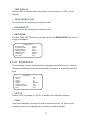
3.3.8 EINSTELLMENÜ 2
EINSTELLMENÜ 2
DREHEN
WINKELJUSTIERUNG
GESCHW. PRO ZOOM
AUTOM. KALIBRIERUNG
PASSWORT
SYSTEM RESET
ENTER
ENTER
AUS
AUS
AUS
JA
SCAN MODE
I
BEENDEN
JA
• DREHEN (FLIP/elektronische oder mechanische Bildumkehr)
Achtung! Wenn die Bildumkehr aktiv ist, wird automatisch die Privacy Masking
Funktion deaktiviert!
Der Beobachter kann ein Objekt kontinuierlich verfolgen, auch wenn es sich unter der
Kamera hindurch bewegt. Hierbei wird das Bild, wenn die Kamera senkrecht nach unten
sieht, elektronisch oder mechanisch umgekehrt. Ohne eine dieser Maßnahmen würde
das Bild, wenn das Objekt sich weiterbewegt, auf dem Kopf stehen. Bei der
elektronischen Lösung bewegt die Kamera sich in der Richtung weiter, in die sie vorher
schon gelaufen ist. Das Bild wird elektronisch gespiegelt.
Vorteil: keine Bildstörung. Bei der mechanischen Lösung wird die Kamera um 180°
gedreht und läuft danach weiter. Hieraus ergibt sich eine geringfügige Störung durch das
schnelle Drehen der Kamera.
(Anm.: ältere Dome - Kameras konnten nicht 180°, sondern nur 90° neigen.)
BILD
Bei senkrechtem Blick nach unten wird das Bild, wie schon erklärt, elektronisch
gespiegelt. Das ergibt ein kurzes Zucken im Bild.
ME (Mechanischer Flip)
Die Kamera wird, bei senkrechtem Blick nach unten, sehr schnell (400°/s) um 180°
gedreht. Dies kann eine kurze Bildstörung durch das verwischte Bild der Kamera beim
schnellen Drehen verursachen.
Achtung! Falls ein Fixpunkt (für Festpositionen oder Sequenzen) gesetzt
wurde, der nur mit dieser Funktion erreichbar war, wird dieser unerreichbar,
wenn die Bildumkehr deaktiviert ist !
AUS
Schaltet die Flip-Funktion aus.
EINSTELLUNG FLIP
FLIP
BEENDEN
AUS
JA
46
• WINKELJUSTIERUNG (Min/Max)
Mit dieser Einstellung ist es möglich auch Objekte zu sehen, die sich bis zu
10° oberhalb der horizontalen Blickrichtung (+/-100) befinden. Das Maximum
der Auslenkung ist wie folgt einstellbar:
WINKELJUSTIERUNG
MIN WINKEL
MAX WINKEL
BEENDEN + SPEICHERN
-10°
100°
JA
• GESCHWINDIGKEIT/ZOOM
Die manuelle Schwenk-/Neigegeschwindigkeit wird mit zunehmender Brennweite
langsamer.
• AUTOKALIBRIERUNG
Die Dome - Kamera ist auf einen horizontalen Bezugspunkt und auf einen vertikalen
Infrarot - Bezugspunkt eingestellt. Durch Installation oder Wartung kann die Distanz zu
diesen Bezugspunkten verändert werden. Ist diese Funktion eingeschaltet, erkennt die
Dome - Kamera diese Veränderung und setzt automatisch den horizontalen Bezugspunkt
zurück auf die Originalposition.
• PASSWORT
Hier kann ein neues Benutzerpasswort eingesetzt werden. "AUS" ändern auf "EIN"
und mit <ENTER> bestätigen. Im Untermenü mit dem Cursor die Ziffern "0-9"
anwählen und jeweils mit <ENTER> bestätigen. Das neue Passwort muss zur
Bestätigung wiederholt werden. Das werkseitig eingestellte Passwort lautet "9527".
• SYSTEM RESET (Zurückstellen)
Ein Reset stellt die Kamera auf die Werkeinstellungen (Default) zurück.
• SCAN MODUS
Wählen Sie <P> für den Progressive Scan Mode, bzw. <I> für den Interlaced Mode
(Zeilensprungverfahren) aus. Werkeinstellung ist <I>.
Hinweis: Wenn der Scan Mode geändert wurde, MUSS die Kamera einem Kaltstart
unterzogen werden! Nur durch Spannung AUS / EIN wird der neue Scan Mode aktiviert.
Ein Neustart-Kommando wäre nutzlos.
• BEENDEN (EXIT)
Verlassen von <EINSTELLMENÜ 2> und zurück zum <HAUPTMENÜ 1>.
47
3.3.9 ID ANZEIGE
Diese Funktion erlaubt Ihnen die Einblendung der ID-Nummer zur Identifizierung
der Dome - Kamera. Gehen Sie mit dem Joystick im <HAUPTMENÜ> zur Seite 2 und
wählen den Menüpunkt <ID ANZEIGE>. Weitere Informationen zur Dome ID finden Sie
im Abschnitt 2.4 Dome ID Einstellungen.
• AN
Einblendung der ID Adresse des aktiven Domes rechts unten auf dem Bildschirm.
• AUS
Löschen der Einblendung.
3.3.10 TITEL ANZEIGE (Kamera - Titeleinblendung)
Anzeigebereiche können zur leichteren Identifizierung mit einer Texteinblendung
versehen werden.
• AN
Texteinblendung aktiv
• AUS
Texteinblendung aus (auch wenn vorher Titel angelegt wurden)
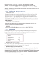
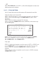
3.3.11 TITEL EINSTELLUNG
Hier können Namen für verschiedene Kamerablickbereiche vergeben werden. Wenn die
Kamera diese Position wieder anfährt, wird der programmierte Name eingeblendet. Bis
zu 16 Titel mit max. 20 Buchstaben pro Titel können eingegeben werden.
Folgende Schritte sind notwendig:
Schritt 1: Bewegen Sie den Dome zu dem Blickbereich, den Sie benennen wollen.
Schritt 2: Schalten Sie das OSD-Menü ein, gehen zur
<HAUPTSEITE 2> und wählen <TITEL EINSTELLUNG>.
Schritt 3: Wählen Sie eine Nummer für diese Position.
Schritt 4: Drücken Sie <ENTER>, um in den Editier-Betrieb zu gelangen.
Schritt 5: Wählen Sie ein Zeichen mit dem Joystick rechts/links aus und drücken Sie
<ENTER>.
48
Beispiel: A "ENTER", B "ENTER", C "ENTER". Als Titel erhalten Sie: ABC
Schritt 6: Um einen Buchstaben zu löschen, bewegen Sie den Cursor auf den
Buchstaben und drücken <ENTER>, dann auf <LÖSCHEN> und ebenfalls <ENTER>.
Schritt 7: Bewegen Sie den Cursor auf <SPEICHERN> und drücken <ENTER> um die
Einstellungen zu speichern.
3.3.12 VORGABE (Festpositionen)
• VOREINSTELLUNG
Bewegen Sie die Kamera zum gewünschten Bildausschnitt. Wenn der Cursor blinkt,
GUFNHQSie <ENTER>, um den eingestellten Zielpunkt 1 zu setzen. Wiederholen
Sie dies für Punkt 2, 3, etc. Insgesamt können 256 Zielpunkte vorgewählt werden.
(*) Achtung! :HQQGLH)3V via GscTelecontrol/MBegEHGLHQWZHUGHQVLQGdiverse
)HVWSRVLWLRQHQNICHTDQZlKOEDUGDVLHIUGHQ$XIUXIVSH]LHOOHU)XQNWLRQHQGLHQHQ
6LHKH$SSHQGL[&.
• VOREINSTELLUNG AUSFÜHREN
Wählen Sie den Zielpunkt, den Sie ansteuern wollen. Drücken Sie <ENTER>, und
die Dome - Kamera wird den Zielpunkt anfahren.
• BEENDEN
Verlassen des <VORGABE> Menüs> und zurück zur <HAUPTSEITE 2>.
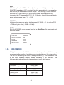
3.3.13 SEQUENZ
Diese Funktion führt eine Sequenz von vordefinierten Einstellungen für Schwenken,
Neigen, Zoom und Fokus aus. Bevor Sie eine Sequenz einstellen, müssen Sie 2
Vorgabepunkte definieren, die die Kamera anlaufen soll.
SEQUENZ
SEQUENZ LINIE
SEQUENZ PUNKT
VORGABE POSITION
GESCHWINDIGKEIT
HALTEZEIT
SEQUENZAUSFÜHREN
BEENDEN
1
01
001
01
001
ENTER
JA
• SEQUENZ LINIE (Sequenzablauf)
Hier können bis zu acht verschiedene Abläufe programmiert werden. Durch Betätigen
des Joysticks rechts/links wird eine "Sequenz Linie" ausgewählt.
• SEQUENZ PUNKT (Sequenz-Haltepunkt)
Es können bis zu 32 Positionen pro Sequenz-Verlauf programmiert werden. Diese Liste
stellt die Verknüpfung mit den programmierten oder noch zu programmierenden
Festpositionen her. "Sequenz Linie" fährt die hier eingegebenen Positionen nacheinander
ab. Dieser Vorgang wiederholt sich so lange, bis "Sequenz" ausgeschaltet oder durch
eine manuelle Anwahl unterbrochen wird.
49
• VORGABE POSITION
Hier können die gewünschten Festpositionen (wenn nicht schon geschehen)
programmiert werden. "BEENDEN" wird benötigt , wenn weniger als 32 Positionen in der
Sequenz angefahren werden sollen. Dies bedeutet, dass z. B. bei nur 5 in der Sequenz
verwendeten Positionen die Festpos. 6 als Endpunkt markiert werden muss!
• GESCHWINDIGKEIT
Hier kann die Schwenk-/Neigegeschwindigkeit der Kamera während der Sequenz
gewählt werden, von 1 (langsam) bis 15 (schnell). SCHWENKEN variiert von 10 bis
400°/s und NEIGEN von 8 bis 400°/s.
• HALTEZEIT (Verweilzeit in Sekunden)
Für die hier eingestellte Zeit verweilt die Kamera auf der jeweiligen Position, bevor sie zur
nächsten Position weiterfährt. Die Verweilzeit kann zwischen <0> bis <127> Sekunden
eingestellt werden. Ist die Verweilzeit <0>, verbleibt der Dome an dieser Position für
weniger als 1 Sekunde und wechselt dann zur nächsten Position.
• SEQUENZ AUSFÜHREN
Mit diesem Kommando wird die Sequenzfunktion gestartet.
• BEENDEN
Verlassen des <Sequenz> Menüs.
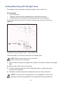
3.3.14 AUTOMATISCHES SCHWENKEN
"AutoPan" ist das automatische kontinuierliche Schwenken der Kamera zwischen zwei
programmierten Punkten: dem Start- und dem Endpunkt. Wird für Start- und Endpunkt
AUTOMATISCHES SCHWENKEN
AUTOM. SCHWENKEN LINIE
STARTPUNKT
ENDPUNKT
RICHTUNG
GESCHWINDIGKEIT
AUTOM. SCHWENKEN AUSFÜHREN
BEENDEN
1
FINDEN
FINDEN
RECHTS
01
ENTER
JA
der gleiche Wert gesetzt, schwenkt die Kamera endlos um 360°.
• AUTOM. SCHWENKEN LINIE (Autopanablauf)
Hier können bis zu vier verschiedene Abläufe programmiert werden. Durch Betätigen des
Joysticks wird eine Autopan Linie ausgewählt.
• STARTPUNKT
Startposition für den Autopanablauf.
>FINDEN<: Durch Drücken von <ENTER> gelangt man in den Joystick-Modus. Mit dem
Joystick kann dann die gewünschte Position eingestellt werden.
>SPEICHERN<: Durch Drücken von <ENTER> wird der Joystick Modus wieder verlassen
und der Startpunkt gespeichert.
50
Achtung: Die Neige- und Zoom-Werte werden aufgezeichnet und gelten für den
gewählten automatischen Schwenkablauf.
• ENDPUNKT
Endposition für den Autopanablauf.
>FINDEN<: Durch Drücken von <ENTER> gelangt man in den Joystick-Modus. Mit
dem Joystick kann dann die gewünschte Position eingestellt werden.
>SPEICHERN<: Durch Drücken von <ENTER> wird der Joystick Modus wieder
verlassen und der Endpunkt gespeichert.
• RICHTUNG
Hier bestimmen Sie die Schwenkrichtung der Dome - Kamera. Der Dome startet z.B. im
Uhrzeigersinn, wenn Sie <RECHTS> als Richtung gewählt haben. Siehe auch
nachfolgende Grafik.
GESCHWINDIGKEIT
Geschwindigkeit der Kamera während der automatischen Schwenkfunktion.
Die Geschwindigkeit ist einstellbar von 1 bis 4 (10 ~ 45°/s).
AUTOM: SCHWENKEN AUSFÜHREN
Start der automatischen Schwenkfunktion.
BEENDEN
Verlassen des Menüs <AUTOM. SCHWENKEN>.
51
3.3.15 KAMERAFAHRT
Es können vier Touren (KAMERAFAHRT) programmiert werden. Hierbei werden die
Joystickkommandos, die Geschwindigkeit und die Zeit aufgezeichnet. Die Tour kann
einen beliebigen Verlauf haben. Es können auch Haltepunkte enthalten sein.
KAMERAFAHRT
KAMERAFAHRTLINIE
1
AUFZEICHNUNG START
ENTER
AUFZEICHNUNG ENDE
ENTER
KAMERAFAHRT AUSFÜHREN ENTER
BEENDEN
JA
• AUFZEICHNUNG START
Startet die Aufzeichnung des Tourverlaufs. Bedienfehler werden natürlich mit
aufgezeichnet. Deshalb vorher einen Plan für den Tourverlauf anlegen.
Schritt 1: Durch Drücken von <ENTER> gelangt man in den Joystick-Modus.
Schritt 2: Jetzt den geplanten Tourverlauf durchführen. Der Cursor im OSD-Menü
bewegt sich automatisch auf "AUFZEICHNUNG ENDE".
Schritt 3: Durch Drücken von <ENTER> den Tourverlauf speichern.
Achtung! Wenn der Speicher vorher die 100% erreicht, wird die Aufzeichnung
automatisch gestoppt!
• AUFZEICHNUNG ENDE
Dieses Kommando beendet die Aufzeichnung des Tourverlaufs.
• KAMERAFAHRT AUSFÜHREN (1 - 4)
Start der <KAMERAFAHRT> Funktion.
• BEENDEN
Verlassen des <KAMERAFAHRT> Menüs.
3.3.16 STARTEINSTELLUNG
Parameter für den Start werden hier eingestellt.
STARTEINSTELLUNG
STARTFUNKTION
MODUS AUSWÄHLEN
VORGABEPUNKT
RÜCKKEHRZEIT
START
BEENDEN
AUS
VORGABE
001
001 MIN.
ENTER
JA
• STARTFUNKTION
Schaltet <STARTFUNKTION> ein oder aus.
52
• AUSWAHL MODUS (AUTOM. SCHWENKEN /SEQUENZ/
KAMERAFAHRT/VORGABE)
Die Kamera führt die hier gewählte Funktion aus, wenn <STARTFUNKTION>
eingeschaltet und die <RÜCKKEHRZEIT> abgelaufen ist.
• VORGABEPUNKT
Geben Sie eine Position ein (1 - 256), die in der STARTPOSITION angefahren werden
soll.
SEQUENZ LINIE
Geben Sie eine Sequenz ein (1 - 8), die in der STARTPOSITION ausgeführt werden soll.
AUTOM. SCHWENKEN LINIE
Geben Sie einen Autopanablauf ein (1 - 4), der in der STARTPOSITION ausgeführt
werden soll.
KAMERAFAHRT LINIE
Geben Sie eine Tour ein (1 - 4), die in der STARTPOSITION ausgeführt werden soll.
• RÜCKKEHRZEIT (in Minuten)
Die Kamera zählt die <RÜCKKEHRZEIT> zurück, nachdem der Bediener die Kamera in
eine beliebige Position bewegt hat.
Die <RÜCKKEHRZEIT> kann eingestellt werden im Bereich von 1 bis 128 Minuten.
• START
Zur manuellen Ausführung (Kontrolle) der STARTFUNKTION. Nur möglich, wenn
STARTFUNKTION ("HOME FUNC ON") eingeschaltet ist.
• BEENDEN
Verlassen des <STARTEINSTELLUNG> Menüs.
MAIN PAGE 3
IR FUNKTION
AUTO
ALARM EINST
ENTER
ALARM DETEKT
AUS
WDR FUNKTION
AUS
PRIVACY MASK
ENTER
ZEIT EINST
ENTER
ZEITPLAN
ENTER
BEENDEN
JA
53
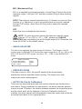
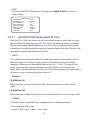
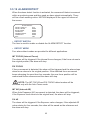
3.3.17 IR FUNKTION (schwenkbarer IR Cut Filter)
Hier wird eingestellt, wie die Farbe/SW-Funktion und das motorisch betriebene IR-Sperrfilter
arbeiten soll.
• AUTOM.
Die Umschaltung zwischen Farbe und SW findet automatisch statt. Bei SW wird das IRSperrfilter aus dem Strahlengang gefahren und die Farbmodulation im Signal (nicht der
Farbhilfsträger!) abgeschaltet. Der Umschaltpunkt von Farbe nach SW und umgekehrt wird
durch die Einstellung <GRENZWERT> (1 - 29) bestimmt.
Ist z. B. der Wert <29> eingestellt und die Kamera befindet sich im Nachtmodus, so wird die
Kamera HUVWHWZDVVSlWHU wieder in den Tagmodus VFKDOWHQDOVEHL!VX
• M$18(//
EIN
Schaltet die IR-Funktion ein (SW-Betrieb).
AUS
Schaltet die IR-Funktion aus (Farb-Betrieb).
• KABEL
Die Umschaltung zwischen Farbe und SW wird hier mit einem potenzialfreien
Kontakt gewährleistet. Hierfür steht der 8. Alarmeingang zur Verfügung:
- geschlossen = S/W-Betrieb; - offen = Farb-Betrieb.
,5GRENZWERT
/,*+76285&(
,5
GRENZWERT
+LHUVLQG:HUWH]ZLVFKHQ!XQG!ZlKOEDU!EHGHXWHWVHKUHPSILQGOLFK
GLH8PVFKDOWXQJYRQ7DJ]X1DFKWEHWULHEHUIROJWEHLFD/X[MHGRFKNDQQHVKLHU
]XU2V]LOODWLRQ]ZLVFKHQ7DJXQG1DFKWEHWULHENRPPHQ %HL!VFKDOWHWGHU'RPH
]ZDUDXFKEHLHWZD/X[LQGHQ1DFKWEHWULHEDEHUGHU:HFKVHOYRQ1DFKW]X7DJ
HUIROJWHUVWZLHGHUZHQQGLH%HOHXFKWXQJVVWlUNHGHQ:HUWYRQFD/X[EHUVFKUHLWHW
'HVKDOELVWHLQ'HIDXOW:HUWYRQ!JHZlKOWhber einen externen.RQWDNW
(z. B. Dämmerungsschalter) kann die Umschaltung manuell und damit
zwangsgesteuert stattfinden.
/,*+76285&(
Hier wird gewählt, ob GLH/LFKWTXHOOH,QIUDURWRGHUVLFKWEDUHV/LFKWLVW
54
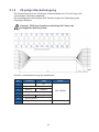
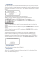
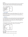
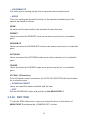
3.3.18 ALARMEINSTELLUNG
Beide Dome stellen 7 + 1* Alarmeingänge (N.O./Normal Offen oder N.C./Normal
Geschlossen) und einen Alarmausgang zum Anschluss von Alarmgeräten bereit. Mit
dieser Funktion kann der Dome mit einem Alarmsystem kooperieren und z.B. Ereignis/Alarmbilder liefern.
In diesem Menü werden die Alarmparameter eingestellt.
ALARMEINSTELLUNG
ALARMKONTAKT
ALARMSCHALTER
ALARM TYP
ALARMAKTION
VORGABEPUNKT
HALTEZEIT
BEENDEN
1
AUS
N.C.
VORGABE
001
IMMER
JA
* 7 Alarmeingänge + Eingang 8 als Tag/Nacht-Umschalter.
• ALARM KONTAKT
Der Dome unterstützt 8 Alarmeingänge und 1 Alarmausgang. Wählen Sie den
Alarmeingang, dessen Alarmparameter Sie einstellen möchten. Anschließend stellen Sie
die Parameter im Menü <ALARMEINSTELLUNG> ein.
Achtung! Wenn z. B. zwei Alarme zeitgleich eintreffen, wird immer die niedrigere
Alarmnummer bearbeitet (z. B. 1+3 gleichzeitig > 1 wird bearbeitet).
• ALARMSCHALTER
Hier wird eine Alarmeingangsfunktion ein- oder ausgeschaltet.
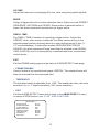
• ALARM TYP
Es gibt zwei Arten von Alarmen, Normal offen (N.O.) und Normal geschlossen (N.C.)
(siehe Darstellung).
Wählen Sie hier den Alarmtyp aus, in dem der Alarmeingang sein muss, um mit Ihrer
Alarmanwendung zu korrespondieren.
55
• ALARMAKTION
Hier wird ausgewählt, welche Funktion bei Eingang eines Alarms ausgeführt werden soll. Es
gibt vier Möglichkeiten.
1. Die Kamera läuft in eine von 256 programmierten Positionen.
2. Es wird eine von acht Sequenzen gestartet.
3. Es wird eine von vier Autoschwenkabläufen gestartet.
4. Es wird eine von vier programmierten Touren gestartet.
• VORGABEPUNKT
Geben Sie eine Position ein (1 - 256), die im Alarmfall angefahren werden soll.
• SEQUENZ LINIE
Geben Sie eine Sequenz ein (1 - 8), die im Alarmfall ausgeführt werden soll.
• AUTOM. SCHWENKEN LINIE
Geben Sie einen Autopanablauf ein (1 - 4), der im Alarmfall ausgeführt werden
soll.
• KAMERAFAHRT LINIE
Geben Sie eine Tour ein (1 - 4), die im Alarmfall ausgeführt werden soll.
• HALTEZEIT (Verweilzeit in Sekunden)
Die Kamera verweilt in der vorgewählten Position für die <HALTEZEIT> in Sekunden.
Danach fährt sie in die vorherige Position zurück. Wenn Sie „IMMER" wählen, bleibt die
Kamera in der angefahrenen Position bis ein neuer Alarm einläuft, der Joystick oder eine
andere Funktion betätigt wird.
Achtung: Die Verweilzeit ist nur einstellbar, wenn Sie VORGABE als Alarmaktion
ausgewählt haben.
• BEENDEN
Verlassen des Menüs <ALARMEINSTELLUNG>.
56
3.3.18.1 ALARMERKENNUNG
Wenn die Alarmerkennungsfunktion aktiviert ist, reagiert die Kamera auf Bewegung in
einem speziellen Sichtbereich und gibt automatisch ein Alarmsignal. Im oberen linken
Bildschirmeck erscheint dann blinkend <MOTION>.
ALARMERKENNUNG
ERK. SCHALTER
ERK.-MODUS
BLOCK MODUS
RAHMEN SETZEN
RAHMEN DEAKT
GRENZWERT
BEENDEN
AUS
KEIN
KEIN
KEIN
KEIN
KEIN
JA
• ERKENNUNGS-SCHALTER
Dieser Punkt wird verwendet, um die ALARMERKENNUNG zu aktivieren.
• ERKENNUNGS-MODUS
Vier Alarmerkennungs-Modi werden unterstützt:
INT FOKUS (Interner Fokus)
Der Alarm wird generiert, wenn der interne Fokus variiert; wenn der Fokus zur
Originalposition zurückkehrt, stoppt der Alarm.
FIX FOKUS
Wenn Fokusbewegung erkannt wird, wird der Alarm generiert; der Alarm stoppt, wenn
der Fokus zur Originalposition zurückkehrt; falls die Fokusbewegung länger als vier
Sekunden dauert, wird die neue Fokusposition als neue Referenz gespeichert und der
Alarm wird gestoppt.
ACHTUNG: die INT FOKUS und FIX FOKUS Modi sind nur im Auto-Fokus-Modus
aktivierbar.
INT AE (Interne AE, Autobelichtung)
Wenn AE-Veränderungen erkannt werden, wird ein Alarm generiert. Wenn der AE-Pegel
zum Ursprungswert zurückkehrt, wird der Alarm gestoppt.
FIX AE (voreingestellter Belichtungswert)
Ein Alarm wird generiert, wenn der Belichtungswert variiert; wenn der justierte AE-Pegel
vier Sekunden lang variiert, wird dieser Wert als neue Referenz gespeichert und der
Alarm danach gestoppt.
BEWEGUNG
Die Bewegungserkennung entdeckt verdächtige Bewegungen und gibt Alarm, wenn der
Bewegungspegel in dem überwachten Bereich den eingestellten
Empfindlichkeitsgrenzwert erreicht oder überschreitet.
57
• BLOCK-MODUS
Im sog. Block-Modus (welchen man AN oder AUS wählen kann) werden Veränderungen,
z. B. verursacht durch Eindringversuche, in den Bereichen des angezeigten Bildes
dynamisch aufgehellt angezeigt.
• RAHMEN SETZEN
In einem angezeigten Bereich kann der Nutzer spezielle Felder setzen. Bitte folgen Sie
den Anweisungen, um die Parameter der sog. "Rahmen" eines jeden
Bewegungserkennungs-bereiches einzustellen. Wenn in einem definierten Rahmen eine
Bewegung erkannt wird, erscheint "MOTION" im oberen linken Bildschirmeck.
Insgesamt 4 Rahmen können gesetzt werden. Wählen Sie einen Rahmen mit dem
Joystick (Rechts/Links) aus und drücken Sie <ENTER>, um ins Submenü zu gelangen.
RAHMEN 1
LINKER RAND
OBERER RAND
HGROESSE
VGROESSE
MODUS
VORG. PUNKT
VERWEILZEIT
BEENDEN
L/R
O/U
-/ +
-/ +
VORGABE
001
001 SEK
JA
LINKER RAND
Bewegen Sie den Rahmen mit dem Joystick (Rechts/Links).
OBERER RAND
Schieben Sie den Rahmen mit dem Joystick an die gewünschte Stelle.
H/V GROESSE
Verändern Sie die Höhe und Breite des Rahmens mit dem Joystick.
MODUS
Wählen Sie eine Reaktion für den eingestellten Rahmen. Zwischen VORGABE,
SEQUENZ, AUTO-SCHWENKEN und KAMERAFAHRT können Sie wählen. Wenn in
einem Rahmen Bewegung erkannt wurde, wird der Dome diese Reaktion ausführen.
VERWEILZEIT
Die VERWEILZEIT ist die Dauer der Reaktion nach Erkennung. Wenn z. B. der
VORGABE-Modus gewählt wird, fährt der Dome zur ausgewählten Festposition und
verweilt dort für die voreingestellte Zeit (1-127 Sek./lmmer). Falls andere Modi
(SEQUENZ/AUTOSCHWENKEN/ KAMERAFAHRT) aktiviert wurden, führt der Dome
diesen Modus so lange aus, bis er durch andere Kommandos dabei unterbrochen wird
(VERWEILZEIT/IMMER).
BEENDEN
Beenden Sie "RAHMEN SETZEN" und kehren zur Seite <ALARMERK.>zurück.
58
• RAHMEN DEAKTIVIEREN
Wählen Sie einen zu deaktivierenden Rahmen und drücken Sie <ENTER>.
Dieser Rahmen verschwindet dann aus dem Anzeigebereich.
• GRENZWERT
Der Grenzwertbereich liegt zwischen 1-255. Je kleiner der Wert, desto empfindlicher ist
der Rahmen; d.h. 1 ist die höchste und 255 die geringste Empfindlichkeit.
• BEENDEN
Beenden Sie das Menü <ALARMERKENNUNG> und fahren Sie fort mit dem
<HAUPTMENÜ 3> und dem Punkt 3.3.19 WDR-FUNKTION.
MAIN PAGE 3
IR FUNKTION
AUTO
ALARM EINST
ENTER
ALARM DETEKT
AUS
WDR FUNKTION
AUS
PRIVACY MASK
ENTER
ZEIT EINST
ENTER
ZEITPLAN
ENTER
BEENDEN
JA
3.3.19 WDR FUNKTION (Erweiterter Dynamikbereich)
Die Einstellungen des erweiterten Dynamikbereiches werden hier vorgenommen. Bei der
WDR-Funktion wird das Bild zweimal mit unterschiedlichen Belichtungszeiten abgetastet.
Mit der normalen und einer kurzen (für die hellen Bildteile). Durch Integration in Echtzeit
(in einem Bildspeicher) werden die beiden Bilder addiert. Man erreicht damit eine
verbesserte Wiedergabe der bei normaler Belichtung überbelichteten Bildteile. Die
Übertragungskennlinie (Gamma) wird dadurch im oberen Pegelbereich stark abgeflacht
und es treten auch keine Überbelichtungseffekte (Auskalken, etc.) auf. Die Wirksamkeit
muss in der praktischen Anwendung überprüft werden.
Wählen Sie <AN>, um die WDR-Funktion zu aktivieren und <AUS>, um sie abzuschalten.
Mit <AUTO> entscheidet die Kamera intern, bei welcher Helligkeit im Bildinhalt die Einoder Abschaltung ausgeführt wird.
Mit <RF> (Ratio Fix = Fester Wert) wird ein bestimmter Wert dieser Bildhelligkeit als
Schaltschwelle festgelegt. Hierbei wird die Shuttergeschwindigkeit für kurze
Belichtungszeiten gefixt und für lange Belichtungszeiten eingestellt, indem dieser Wert
(bezogen auf die kurze Belichtungszeit) als Vergleichsparameter gesetzt wird. Eine sog.
verriegelte Schatten-Korrektur (auch Spitzlicht-Austastung) findet nicht statt.
<DC> (D version compatible = vergleichbar der WDR-Funktion des Vorgänger-Moduls
FCB-EX1010P/D) erlaubt einen WDR-Modus, der ein Histogramm (treppenförmige
Regelung) verwendet, um die vorgenannte Schatten-Korrektur durchzuführen.
59
3.3.20 PRIVACY MASK (ESF Elektronische Sichtschutzfunktion)
Hier können Zonen im Bild programmiert werden, die den Blick der Kamera auf diese
Bereiche verdecken. Die Kamera nimmt zwar weiterhin auch diese Bildbereiche auf, aber
in den Bereichen der programmierten Felder wird das Bildsignal ausgetastet und durch
auswählbare Farben ersetzt. Bei Veränderung des Zooms und der Blickrichtung werden
diese Felder in Größe und Perspektive automatisch angepasst.
Achtung: BILD DREHEN (Flip) und BILDUMKEHRUNG (Image Inverse)
sind automatisch deaktiviert, wenn die PRIVACY MASK Funktion
eingeschaltet ist.
Der Setzbereich für die Masken ist auf 70° vertikal beschränkt.
Außerdem können max. 8 Felder in einer Szene gesetzt werden!
PRIVACY MASK
SICHTSCHUTZ-SCHALTER
TRANSPARENZ
FARBE
MASKE SETZEN
MASKE LÖSCHEN
BEENDEN
AUS
AUS
SCHWARZ
01
01
JA
• SICHTSCHUTZSCHALTER (ESF-Schalter)
Hiermit können die programmierten Maskierungen ein- und ausgeschaltet werden.
• TRANSPARENZ (durchscheinende Maskierung)
Hier kann die Maskierung als (AN) "durchsichtig" oder (AUS) "undurchsichtig" eingestellt
werden (dies dient nur zur vereinfachten Maskensetzung!).
• FARBE
Farbauswahl: Schwarz, Hell/Dunkel-Grau, Weiß, Rot, Grün, Blau, Cyan, Gelb und
Magenta.
• MASKE SETZEN
Bewegen Sie den Dome in den Bereich, den Sie gegen Sicht schützen möcht en. Gehen
Sie zu "Maske setzen" und benennen Sie die Nummer der Maske. Die jetzt sichtbare
Bildschirmmitte ist der Mittelpunkt der ersten Maske. Mit dem unteren bestimmen Sie
Lage und Größe der Masken. Es sind max. 24 Felder setzbar.
MASKIERUNG01 MENÜ
HOR. MITTE
VERT. MITTE
HOR. GRÖSSE
VERT. GRÖSSE
BEENDEN+SPEICHERN
/5
82
000
000
JA
60
HOR. MITTE 000-255
Die normale horizontale Mitte der Maske ist der Mittelpunkt des Bildes. Sie können die
Mitte der Maske, durch Veränderung dieses Wertes, in die gewünschte
Bildschirmposition bewegen.
VERT. MITTE 000-255
Die gleiche Einstellung für vertikal.
HOR. GRÖSSE 000-127
Hiermit wird die Maskierung, durch Veränderung des Wertes, auf die gewünschte Breite
eingestellt.
VERT. GRÖSSE 000-127
Die gleiche Einstellung für die Maskenhöhe. Durch abwechselnde Veränderung dieser
vier Werte, wird die Maskierung auf die gewünschte Größe und Position eingestellt.
• MASKE LÖSCHEN
Mit dieser Funktion können Masken gelöscht werden. Verfahren Sie wie folgt:
1. Wählen Sie die Maskenzone, die gelöscht werden soll (z.B. 01).
2. Drücken Sie <ENTER> zur Bestätigung Ihrer Auswahl.
• SPEICHERN und BEENDEN
Wenn Sie die Masken eingestellt haben, müssen Sie diese Zeile mit dem Cursor
anwählen und mit <ENTER> verlassen.
3.3.21 ZEITEINSTELLUNG (Uhrzeit/Datum-Funktion)
Einstellung der Uhrzeit/Datum-Einblendung in das Kamerabild. Sie dient u. A. dazu, das
Menü "ZEITPLAN" zu programmieren.
ZEITEINST.
ZEITANZEIGE
JAHR EINSTELLEN
MONAT EINSTELLEN
TAG EINSTELLEN
STUNDE EINSTELLEN
MINUTE EINSTELLEN
BEENDEN+SPEICHERN
AUS
00
01
00
00
00
JA
• ZEITANZEIGE
Bei Auswahl von "AN" wird Uhrzeit/Datum im Bild angezeigt. Bei "AUS" nicht.
• JAHR/MONAT/TAG)
Hier werden die o. g. Werte eingestellt.
• STUNDE/MINUTE
Hier werden die o. g. Werte eingestellt.
• BEENDEN UND SPEICHERN
Verlassen des Menüs <ZEITEINSTELLUNG>.
61
3.3.22 ZEITPLAN (Termin/Zeitplanung)
Die Terminplanfunktion ermöglicht es, in einem bestimmten Zeitrahmen automatisch
einen bestimmten VORGABEPUNKT anzufahren oder eine bestimmte Funktion
(SEQUENZ/AUTOM. SCHWENKEN/KAMERAFAHRT) auszuführen.
ZEITPLAN
ZEITPL. SCHALTER
ZEITPUNKT
ZEITPLAN STUNDE
ZEITPLAN MINUTE
ZEITPLAN MODUS
VORGABEPUNKT
ZEITPLAN ZURÜCKS.
ZEITPLAN BEENDEN
AUS
00
00
00
VORGABE
001
JA
JA
• ZEITPLAN SCHALTER
Schaltet die Terminplanfunktion ein <AN> oder aus <AUS>
• ZEITPUNKT
Ermöglicht dem Nutzer 32 verschiedene Zeitabläufe zu programmieren.
• ZEITPLAN STUNDE/MINUTE
Hier werden Stunden und Minuten für die verschiedenen Zeitabläufe eingetragen.
• ZEITPLAN MODUS (Aktionen nach Zeitplan)
Hier kann programmiert werden, welche Funktion an der jeweiligen Stelle des Zeitplans
ausgeführt werden soll.
KEINE
Es wird keine Funktion ausgeführt.
VORGABE
Bis zu 256 Festpositionen können eingestellt werden.
SEQUENZ
Bis zu 8 Sequenzabläufe können eingestellt werden.
AUTOM. SCHWENKEN
Bis zu 4 Autopanabläufe können eingestellt werden.
KAMERAFAHRT
Bis zu vier Tourabläufe können voreingestellt werden.
IR FUNKTION
Die IR-Funktion "AUTO" kann damit ein- oder ausgeschaltet werden.
• ZEITPLAN ZURÜCKSETZEN
In diesem Menüpunkt kann die komplette Terminplanfunktion auf 0 (Ausgangspunkt)
zurückgesetzt werden.
• ZEITPLAN BEENDEN
Verlassen des <ZEITPLAN> Menüs.
62
3.3.23 BEENDEN OSD
Um das OSD Setup-Menü zu verlassen, wählen Sie diesen Menüpunkt mit dem Joystick
an und bestätigen ihn mit <CAMERA OFF> (= ENTER).
63
Anhang A: Technische Daten GNSD882
Technische Daten
Bildaufnehmer (Chip)
Abtastsystem
Abtastfrequenz
Pixel (H x V)
Horizontale Auflösung
Minimale Empfindlichkeit:
Farbe
S/W
Synchronisation
Signal/Rauschverhältnis
Weißabgleich
Shutter
Gegenlichtkompensation
Automatische Verstärkungsregelung (AGC)
Erweiterter Dynamikbereich
LAN-Schnittstelle
Übertragung
Kompression/Kodierung
Farb- / S/W-Umschaltung
Elektronische Sichtschutzfunktion
(Privacy masking)
Objektiv
Zoomfaktor (Optisch)
Zoomfaktor (Digital)
Bildstabilisierung
Stabiler Zoom
Schwenkbereich
Neigebereich
Schwenk-/Neigegeschwindigkeit
Geschwindigkeit bei Festpositionen
Anfahrgenauigkeit
Automatisches Wechseln der Blickrichtung
(Auto Flip)
Automatische Fokussierung (Auto Fokus)
Anzahl Festpositionen
VIPCAM-GNSD882
1/4" Sony EX-View HAD Sensor
Progressive Scan
15,625 kHz (H), 50 Hz (V)
752 x 582 (effektiv)
550 TV-Linien
0,1 Lux (50 IRE); IR Cut Filter, AGC eingeschaltet
0,01 Lux (50 IRE); IR Pass Filter, AGC eingeschaltet
Intern / Extern (Netzsynchronisation)
>50 dB (AGC ausgeschaltet)
Automatisch / Manuell
An / Aus - Manuell/Automatisch elektronisch (AES), 1/1,5 bis
1/4000 s
An / Aus
Automatisch / Manuell
Ja
RJ45 Anschluss, 10/100Base-TX
TCP (Transmission Control Protocol)
Bilder werden direkt im GeViScope kompatiblen Datenformat
übertragen: MPEG4CCTV
Automatisch (IR-Schwenkfilter)
24 Sichtschutzzonen einstellbar über On Screen Menü
3,4 mm bis 122,4 mm (Optisch)
36fach
1fach - 12fach proportional
Ja
Ja
360° endlos schwenken
-10° bis 190°
1°/s bis 90°/s (Manuell)
5°/s bis 400°/s (Schwenken/Neigen)
0,225° (Schwenken), 0,45° (Neigen)
Ja
Automatisch / Manuell
256 Festpositionen mit Standbildfunktion*
!V$EVFKQLWWX8VLQGQXU)HVWSRVLWLRQHQYHUIJEDU
Sequenz-Modus
Kontur-Modus (Patrouille)
Automat. Schwenken
Eingebaute Protokolle
Betriebstemperatur
Luftfeuchtigkeit bei Betrieb
Schutzklasse
Spannungsversorgung
Leistungsaufnahme
Abmessungen in mm (D x H)
Gewicht
Zertifikate
Ja; 8 x
Ja; 4 x
Ja; 4 x
JVC/Geutebrück Protokoll
- 50 °C bis + 50 °C
0 % bis 90 % rel. Luftfeuchte (nicht kondensierend)
IP 66 mit Sonnenschutzdach
24 V AC
Ca. 65 W (mit Heizung)
233,5 x 302,5
Ca. 2,6 kg
CE, FCC
64
Anhang A: Technische Daten GNSD682
Technische Daten
Bildaufnehmer (Chip)
Abtastsystem
Abtastfrequenz
Pixel (H x V)
Horizontale Auflösung
Minimale Empfindlichkeit:
Farbe
S/W
Synchronisation
Signal/Rauschverhältnis
Weißabgleich
Shutter
Gegenlichtkompensation
Automatische
Verstärkungsregelung (AGC)
Erweiterter Dynamikbereich
LAN-Schnittstelle
Übertragung
Kompression/Kodierung
Farb- / S/W-Umschaltung
Elektronische Sichtschutzfunktion (Privacy masking)
Objektiv
Zoomfaktor (Optisch)
Zoomfaktor (Digital)
Bildstabilisierung
Stabiler Zoom
Schwenkbereich
Neigebereich
Schwenk-/Neigegeschwindigkeit
Geschwindigkeit bei
Festpositionen
Anfahrgenauigkeit
Automatisches Wechseln der
Blickrichtung (Auto Flip)
Automatische Fokussierung
(Auto Fokus)
Anzahl Festpositionen
Sequenz-Modus
Kontur-Modus (Patrouille)
Automat. Schwenken
Eingebaute Protokolle
Betriebstemperatur
Luftfeuchtigkeit bei Betrieb
Schutzklasse
Spannungsversorgung
Leistungsaufnahme
Abmessungen in mm (D x H)
Gewicht
Zertifikate
Bestell-Nr.
VIPCAM-GNSD682
1/4" Sony EX-View HAD Sensor
Progressive Scan
15,625 kHz (H), 50 Hz (V)
752 x 582 (effektiv)
550 TV-Linien
0,1 Lux (50 IRE); IR Cut Filter, AGC eingeschaltet
0,01 Lux (50 IRE); IR Pass Filter, AGC eingeschaltet
Intern / Extern (Netzsynchronisation)
>50 dB (AGC ausgeschaltet)
Automatisch / Manuell
An / Aus - Manuell/Automatisch elektronisch (AES), 1/1,5 bis 1/4000 s
An / Aus
Automatisch / Manuell
Ja
RJ45 Anschluss, 10/100Base-TX
TCP (Transmission Control Protocol)
Bilder werden direkt im GeViScope kompatiblen Datenformat übertragen:
MPEG4CCTV
Automatisch (IR-Schwenkfilter)
24 Sichtschutzzonen einstellbar über On Screen Menü
3,4 mm bis 122,4 mm (Optisch)
36fach
1fach - 12fach proportional
Ja
Ja
360° endlos schwenken
-10° bis 190°
1°/s bis 90°/s (Manuell)
5°/s bis 400°/s (Schwenken/Neigen)
0,225° (Schwenken), 0,45° (Neigen)
Ja
Automatisch / Manuell
256 Festpositionen mit Standbildfunktion*
!V$EVFKQLWWX8VLQGQXU)HVWSRVLWLRQHQYHUIJEDU
Ja; 8 x
Ja; 4 x
Ja; 4 x
JVC/Geutebrück Protokoll
- 10 °C bis + 45 °C; (0 °C bis 40 °C empfohlen)
0 % bis 90 % rel. Luftfeuchte (nicht kondensierend)
IP 20 (zum Betrieb in trockenen Räumen)
24 V AC
Ca. 20 W
131 x 226
Ca. 1,6 kg
CE, FCC
0.34873
65
Anhang B: Verfügbares Zubehör
Die folgenden Abschnitte zeigen verschiedene Zubehöre und Möglichkeiten, die
Domekameras zu installieren.
Beachten Sie: Die Maueranker mit Sechskantmutter gehören nicht zum
Lieferumfang. Verwenden Sie Befestigungsteile (Maueranker, Dübel, evtl.
Schwerlastdübel), die für das Zubehör geeignet sind.
Netzteil/Montagebox PSU-24VAC/80VA/Boxed (5.14040)
Es wird empfohlen, dieses Zubehör unbedingt zur Montage und Anschluss des
GNSD882 und des GNSD682 zu verwenden.
66
Bracket Wall Mount GSD/BWM-003 (5.04802)
Wandhalter für GNSD882 im Außenbereich (und in Verbindung mit einem DomeMontage-Adapter GSD/BDA-001; 5.04866, auch für den GNSD682 im Innenbereich zu
verwenden!).
Abmessungen in mm (B x H x T): 114 x 138 x 350
Material: Aluminium-Druckguss (Pulverbeschichtet)
Gewicht: ca. 1,5 Kg / Farbe: RAL 7032
Führen Sie die folgenden Schritte
aus, um den Wandhalter zu
montieren.
1) Machen Sie ein
Kabeleingangsloch an der Wand,
wenn erforderlich.
2) Schrauben Sie die Montageplatte des Halters auf der Wand fest.
3) Führen Sie das Kabel in den Wandhalter und durch den Domedeckel ein.
4) Montieren Sie den Domedeckel am Wandhalter mit Hilfe der beigefügten
Schrauben und Dichtungsringe und verbinden das Kabel mit dem Dome.
5) Befestigen Sie die Kuppelkamera am Domedeckel und ziehen Sie die Schrauben fest.
67
Bracket Ceiling Mount GSD/BCE-002 (5.04801)
Deckenabstandrohr für GNSD882
Der Deckenhalter ist ausschließlich für den Einsatz in geschlossenen Räumen
geeignet.
Abmessungen in mm (B x H x T): 140 x 250
Gewicht: ca. 1 Kg / Farbe: EHLJH
Führen Sie die folgenden Schritte aus, um das Abstandrohr an der
Decke zu montieren.
1) Stellen Sie sicher, dass die Decke das Gewicht der Domekamera,
des Domedeckels und des Abstandrohres tragen kann.
2) Machen Sie ein Kabeleingangsloch in der Decke.
3) Schrauben Sie die Montageplatte des Abstandrohrs an der Decke
fest.
4) Führen Sie das Systemkabel durch das gerade Rohr und den
Domedeckel ein und verbinden Sie den Domedeckel am Abstandrohr
mit den beigefügten Schrauben und Dichtungen.
5) Verbinden Sie das Systemkabel mit dem Dome.
6) Befestigen Sie den Dome am Halter (siehe Bedienungsanleitung)
und ziehen Sie die Schrauben fest.
Bitte achten Sie darauf, dass kein Wasser durch das Abstandrohr eintritt, da die
Elektronik des Domes beschädigt werden kann.
68
Corner Mount Adapter GSD/CMA-003 (5.04806)
Eckmontageadapter für GNSD882 (und in Verbindung mit einem Dome-Montage-Adapter
GSD/BDA-001; 5.04866, auch für den GNSD682 zu verwenden).
Verwendung nur in Kombination mit dem Wandhalter GSD/BWM-003 (5.04802)
Abmessungen in mm (B x H x T): 206 x 222 x 121
Material: Stahlblech (Pulverbeschichtet)
Gewicht: Ca. 2 Kg / Farbe: RAL 7032
Mit einer Eckmontageplatte und dem Wandhalter
GSD/BWM-003 (5.04802, separat zu bestellen), kann
die Domekamera an eine Ecke montiert werden.
1) Machen Sie ein Kabeleingangsloch in der Wand,
wenn erforderlich.
2) Befestigen Sie die Eckmontageplatte mit geeignetem
Montagematerial an der Wand.
3) Befestigen Sie den Wandhalter an der
Eckmontageplatte.
4) Für die Installation der Kabel, gehen Sie wie in
2.3.2.3 beschrieben vor.
69
Pole Mount Adapter GSD/PMA-003 (5.18374)
Mastmontageadapter für Tag/Nacht Außen-Dome GNSD882
Verwendung nur in Kombination mit GSD/BWM-003 (5.04802)
Abmessungen in mm (B x H x T): 137 x 182 x 50
Material: Edelstahl (1.4571)
Gewicht: (inkl. Zubehör): ca. 1,0 Kg
Zubehör: 2 x Spannband mit Schloss und 4 x 6-Kantschraube M8 x 30
Für die Schlösser wird ein Inbus M 5 benötigt.
Führen Sie die Schritte aus, um den Mastadapter und den Wandhalter GSD/BWM-003
(5.04802 separat zu bestellen), zu montieren.
1) Befestigen Sie den Masthalter mit den
rostfreien Spannbändern
an einem Mast.
2) Befestigen Sie den Wandhalter GSD/BWM003 (5.04802) auf dem Masthalter.
3) Führen Sie das Systemkabel durch das
Rohr des Wandhalters und den Domedeckel ein
und verbinden Sie es mit der Domekamera.
4) Für die Installation der Kabel gehen Sie wie
in 2.3.2.3 beschrieben vor.
70
Wandmontagezubehör für GNSD682
Wandhalter GSD/BWM-001 (5.04864)
Wandhalter GSD/BWM-001
Weiß; 184 x 104 x 115.2 mm
mit zugehörigen Schrauben, Dichtungen und U-Scheiben
Dome-Montageadapter GSD/BDA-001 (5.04866)
Montageadapter
Zur Montage des GNSD682 an einen Wandhalter oder Abstandsrohr.
Weiß; Durchmesser 140 mm; Höhe: 74 mm
Beigefügtes Zubehör: Innensechskantschlüssel, Sicherungsplatte und 3 Schrauben
71
Deckenmontagezubehör für GNSD682
Deckenmontage-Kit (im Lieferumfang enthalten)
Deckenmontage-Kit
Für Aufputzmontage. Höhe: 214mm; Durchmesser Bohrungen: 45mm;
Durchmesser Montagelochkreis: 158mm
Deckeneinbau-Kit GSD/BFC-001 (5.04860)
Deckeneinbau-Kit
Zum Deckeneinbau.
Höhe: 170 mm; Durchmesser: 180 mm; 05 .g
72
Deckenhalter GSD/BPE-001 (5.04862)
Deckenhalter für GNSD-682
Weiß; Höhe: 250 mm; Durchmesser: 50 mm
1 .g mit zugehörigen Schrauben, Dichtungen und U-Scheiben,
1 x weisse Gummiabdeckung.
73
Preface
The information given in this manual was up to date when published. The company
reserves the right to revise and improve its products. All specifications are subject to
change without notice.
Notice
To work with the Integrated IP High Speed Dome Cameras, any installer or technician
must have the following minimum qualifications:
• A basic knowledge of CCTV and IP systems and components
• A basic knowledge of electrical wiring and low-voltage electrical hookups
• Have read this manual completely
Copyright
Under copyright laws, the contents of this user manual may not be copied,
photocopied, translated, reproduced or reduced to any electronic medium or machinereadable format, in whole or in part, without prior written permission of the company.
Important Information
Before proceeding, please read and observe all instructions and warnings in this
manual. Retain this manual with the original bill of sale for future reference and, if
necessary, warranty service. When unpacking your unit, check for missing or damaged
items. If any item is missing, or if damage is evident, DO NOT INSTALL OR
OPERATE THIS PRODUCT. Contact your dealer for assistance.
Regulation
This device complies with Part 15 of the FCC Rules. Operation is subject to the
following two conditions:
(1) this device may not cause harmful interference, and (2) this device must accept any
interference received, including interference that may cause undesired operation.
Attention please!
We highly recommend, to use network cable with category 6 or higher for network
application of the VIPCAM domes.
Also it is recommended to fullfil the EMC specification. Therefore you must apply ferrite
beads to the network- and system cable nearby the dome connections (see pictures).
1
The grey ferrite bead must be applied to the power cable, the black one to the network
cable. Than press them together. Please fix the ferrite beads with cable straps.
The distance between the ferrite beads must be 40 mm at least, because they did not fit
to the straight tube or gooseneck side by side.
Cautions
•
Handle the camera carefully
Do not abuse the camera. Avoid striking, shaking, etc. The camera could
be damaged by improper handling or storage.
•
Do not disassemble the camera
To prevent electric shock, do not remove screws or covers. There are no
user serviceable parts inside. Ask a qualified service person for
servicing.
•
Do not operate the camera beyond the specified temperature, humidity or
power source ratings
Use the camera under conditions where temperature is between -50°C ~
+50°C ( -58°F ~122°F) and humidity is below 90%.
•
Do not use strong or abrasive detergents when cleaning the camera body
Use a dry cloth to clean the camera when dirty. In case the dirt is hard to
remove, use a mild detergent and wipe gently.
•
Never face the camera towards the sun
Do not aim the camera at bright objects. Whether the camera is in use or
not, never aim it at the sun or other extremely bright objects. Otherwise,
the camera sensor may be smeared or damaged.
2
Inhalt
1.
1.1
2.
2.1.1
2.1.2
2.1.3
2.1.4
2.1.5
2.1.6
2.2
2.3
2.3.1
2.3.2
2.4
2.5
3.
3.1
3.2
3.2.1
3.3
3.3.1
3.3.2
3.3.3
3.3.4
3.3.5
3.3.6
3.3.7
3.3.8
Overview .............................................................................................................. 5
Product Features .................................................................................................. 6
Connecting the High Speed Domes GNSD882 / GNSD682 ............................. 7
Package Contents GNSD882 ........................................................................... 7
Package Contents GNSD682 ........................................................................... 8
Switch Definition ............................................................................................... 9
Dome Control Protocol Setting (Switch D) ........................................................ 10
22-Pin Connector Definition .............................................................................. 11
Alarm Pin Definition .......................................................................................... 12
Installation of the GNSD882 ............................................................................. 13
Installation of the GNSD682 ............................................................................. 16
Ceiling Mount ................................................................................................... 16
Hard Ceiling Mounting ...................................................................................... 17
In-Ceiling Mounting........................................................................................... 19
Ceiling Mounting with Straight Tube ................................................................. 22
Wall Mount / Mini Pendant Mount ..................................................................... 24
System versions to remote control IP domes via MBeg/GCT-3X-LAN ............. 25
Commissioning of IP Domes in GSC-Setup ..................................................... 29
Operation and Configuration ............................................................................. 36
Display Format ...................................................................................................... 36
OSD Menu Tree .................................................................................................... 37
OSD Menu Tree GNSD882/GNSD682 ................................................................. 37
Configuration Menu .............................................................................................. 40
LANGUAGE ...................................................................................................... 41
DEFAULT CAMERA ........................................................................................... 42
BACKLIGHT COMPENSATION .......................................................................... 42
FOCUS
...................................................................................................... 42
AE MODE
...................................................................................................... 43
WBC MODE ...................................................................................................... 44
SETUP MENU 1 ................................................................................................. 46
ZOOM SPEED.................................................................................................... 46
DIGITAL ZOOM .................................................................................................. 46
SLOW SHUTTER ............................................................................................... 46
IMAGE INVERSE ............................................................................................... 46
FREEZE ............................................................................................................. 47
APERTURE ........................................................................................................ 47
STABILIZER ....................................................................................................... 47
STABLE ZOOM .................................................................................................. 48
EXIT ................................................................................................................... 48
SETUP MENU 2 ................................................................................................. 48
FLIP
...................................................................................................... 48
3
ANGLE ADJUSTER ............................................................................................ 49
SPEED BY ZOOM .............................................................................................. 49
AUTO CALI (Auto Calibration) ............................................................................ 49
PASSWORD ....................................................................................................... 50
SYSTEM RESET ................................................................................................ 50
SCAN MODE ...................................................................................................... 50
EXIT .................................................................................................................... 51
3.3.9 ID DISPLAY ...................................................................................................... 51
3.3.10 TITLE DISPLAY .................................................................................................. 51
3.3.11 TITLE SETTING .................................................................................................. 52
3.3.12 PRESET
.................................................................................................... 53
3.3.13 SEQUENCE .................................................................................................... 54
3.3.14 AUTOPAN
.................................................................................................... 55
3.3.15 CRUISE
.................................................................................................... 57
3.3.16 HOME SETTING ................................................................................................. 58
3.3.17 IR FUNCTION (Removable IR Cut)..................................................................... 60
3.3.18 ALARM SETTING ............................................................................................... 62
3.3.19 ALARM DETECT ................................................................................................. 65
3.3.20 WDR FUNCTION ................................................................................................ 68
3.3.21 PRIVACY MASK ................................................................................................. 68
3.3.22 TIME SETTING ................................................................................................... 70
3.3.23 SCHEDULE .................................................................................................... 71
3.3.24 EXIT OSD
.................................................................................................... 72
Appendix A: Technical Specifications GNSD882/GNSD682 ...................................... 73
Appendix B: Available Accessories............................................................................. 75
For Installation GNSD882 ................................................................................................ 75
Power Supply PSU-24VAC/80VA/Boxed (5.14040) ........................................................ 75
Bracket Wall Mount GSD/BWM-003 (5.04802) ............................................................... 76
Bracket Ceiling Mount GSD/BCE-002 (5.04801) ............................................................. 77
Corner Mount Adapter GSD/CMA-003 (5.04806) ............................................................ 78
Pole Mount Adapter GSD/PMA-003 (5.18374) ................................................................ 79
For Installation GNSD682 ................................................................................................ 80
Power Supply PSU-24VAC/80VA/Boxed (5.14040) ........................................................ 75
Mini Pendant GSD/BWM-001 (5.04864).......................................................................... 80
Indoor Mount Kit GSD/BDA-001 (5.04866)...................................................................... 80
T-Bar Mounting GSD/BFC-001 (5.04860) ....................................................................... 81
Straight Tube GSD/PBE-001 (5.04862)........................................................................... 82
Appendix C: Remote Control Protocol KDec->JVC TK-C676 (German only) .......... 83
4
1.
Overview
The new subcompact Integrated High-Speed IP-Dome is designed todeliver superb
performance and durability with an intelligent and stylish housing that is suitable in any
security and surveillance installation. The latest Dome Camera possesses the additional
functions of Image Inverse and multi-language OSD operation. The dome camera also
supports easy installation and can be integrated with various digital surveillance products,
such as Digital Video Recorders (DVRs), our Control Keyboard MBeg/GCT-3X-LAN or
other IP accessories for a complete surveillance solution.
The Dome Camera delivers up to 432x zoom ratio to capture clear image in the distance.
Continuous Auto Focus, Back Light Compensation, Auto Exposure and Digital Slow
Shutter functions are provided for clear and high quality image. Removable IR cut filter
ensures 24 hours operation, while Privacy Masks are specially designed to avoid any
intrusive monitoring at specific region; all of the salient functions can be incorporated to
meet your needs. The Home function allows users to specify a preset position as the
‘home position’ or homefunctions (Sequence/Auto-pan/Cruise). In this mode, Dome
Cameras can come back to the preset home position or functions when the camera has
been idle for a user-defined period of time. Additionally, the unique Schedule function
enables users to program a preset point or function (Sequence/Auto-pan/Cruise) so that
these actions can be automatically performed in certain period of time.
The Dome Camera provides variable pan/tilt speeds ranging from a fast patrol of
400°/s to a slow ramble of 0,5°/s with 0.225° pan accuracy for fast and accurate
tracking ability. The 360° endless rotation and -10°~ +190° tilt travel make tracking the
object passing directly beneath the dome. Maximum 256 preset points can be
programmed for precise location of target areas and users can also define 8
sequence, 4 auto-pan and 4 cruise routes for the camera to operate automatically.
The Integrated IP High Speed IP-Dome provides 7 + 1* alarm inputs and 1 alarm relay
output; the smart alarm management mechanism can be programmed through the
OSD setup menu. Certain function (Preset/Sequence/Auto-Pan/Cruise) can be
activated when an alarm is triggered.
(* = Alarm Input 8 is reserved for Day/Night switch; open = day mode, closed =
night mode)
Built-in protocols provide connectivity to other surveillance systems. The built-in protocols
include JVC and JVC/GEUTEBRUECK, which allow the Dome Camera series to be
integrated with other suppliers' surveillance systems.
Dependability and ultra high reliability are key factors in the Dome Camera’s design cycle.
Every speed dome is assembled with meticulous care and thorough testing at our ISO
9001 compliant factory. High performance, reliability and reasonably pricing make this
speed dome to be an ideal solution to users’ tough surveillance requirement.
5
1.1 Product Features
Precise and Accurate Performance
•
Auto Calibration
•
Preset accuracy of 0.225°
•
Preset speed up to 400r/sec.
•
Proportional Pan & Tilt Speed
•
Preset Position/Sequence /Auto-Pan /Cruise
Dynamic Applications
•
Multi-language OSD
•
Schedule function
•
Multiple built-in Protocols
•
Up to 24 masking zones
•
7 + 1 alarm inputs, 1 alarm output
•
Alarm Detection
•
•
•
•
Flexible indoor/outdoor mountings
Compact lightweight design for easy installation
Weather resistant housing
All-in-one type
Superior Camera Image Quality
•
Minimum illumination 0.01 Lux (B/W)
•
Digital Slow Shutter
•
Electronic Shutter
•
Wide Dynamic Range
•
Auto White Balance
•
Backlight Compensation
•
Auto Exposure
•
Image Inverse and Freeze function
•
Removable IR Cut Filter
Password protected OSD
Video-DSP and Ethernet/IP-Interface for GeViScope system integration:
One of both DSPs (Digital Signal Processor) in this camera is a high-performance VideoDSP specially provided for the integration of the camera into the Geutebrück GeViScope
system. This DSP performs all functions of preprocessing a video signal in the same
manner a GeViScope does, e.g., video signal compression and motion detection. In
conjunction with an Ethernet/IP-interface, instead of an analog video cable between the
camera and the GeViScope an Ethernet connection can be used without losing any
functionality or performance as it is the case with usual IP cameras.
6
2. Connecting the High Speed Domes GNSD882 /
GNSD682
Please refer to the following sections to connect, set and operate the dome camera. In
order to control the integrated high speed IP-domes, basically our control keyboard
MBeg/GCT-3X-LAN or GSC-Telecontrol is required.
2.1.1 Package Contents GNSD882
Before proceeding, please check WKDWthe box contains the items listed here.
,IDQ\item is missing or has defects, DO NOT install or operate the product
DQGcontact your dealer for assistance.
Lubricant
Screws
130-cm Data Cable
Dome Body
22 - pin
2 x Ferrite bead
Optical Cover
Waterproof rubber
7
User’s Manual
2.1.2 Package Content GNSD682
Before proceeding, please check WKDWthe box contains the items listed here. If any
LWHPLVmissing or has defects, DO NOT install or operate the product and contact
\RXUdealer for assistance.
Dome Body
130-cm Data Cable 22 - pin
2 x Ferrite bead
Decoration Ring
User’s Manual
8
2.1.3
Switch Definition
First of all, checking the dome ID and communication protocol is required before
connecting the dome camera to other devices. The switches used for configuring
these settings are located on the bottom of the dome camera.
A
Reserved
B
Not used
C
Dome ID Switch (must be 001)
D
Dome Protocol Switch (must be 20)
E
22-Pin Connector
F
RJ-45 Connector
9
2.1.4
Dome Control Protocol Setting (Switch D)
Switch No.
Protocol
Baud Rate
15
JVC
9600
20
JVC/GEUTEBRÜCK
9600
Select protocol: JVC/GEUTEBRÜCK, with switch no. 20 and baud rate 9600, for
instance, the protocol switch should be set as below.
Decimal Digit Single Digit
NOTE: The number “0” should locate upwards as shown in above diagram
for correct switch definition.
Interface parameter:
9600 baud
8 data bit / 1 stop bit with parity even
Half duplex / no handshake
Switch D -> Nr. 20
10
22-Pin Connector Definition
2.1.5
A 130-cm data cable (shown as the figure below) is shipped with the integrated
high speed IP-dome for quick installation. Additionaly, the section will also provide
the definition of each pin within the 22-pin connector on the data cable.
CAUTION: Before connecting the cable please be sure,
that you are using the correct cable colors !
Funktion und Kennzeichnung der Anschlüsse:
No.
Function
1
AC24-1
2
Alarm Pin
3
AC24-2
4
Alarm Pin
5
FG
6
Alarm Pin
11-20
Alarm Pin
Cable
Color
Red
Black
1007 20AWG
Yellow
11
2.1.6 Alarm Pin Definition
The alarm pins are serviceable for connecting alarm in- and output devices. Following lists
the definition of alarm pin on the 22-pin connector located on the bottom of the dome
camera.
Pin
2
Color
White
Definition
ALM NO
4
Black/White
ALM NC
6
Green/Black
ALM COM
11
Blue/White
12
Red/White
Purple
13
14
15
16
Grey
Blue
ISO
ALMALMALMALMALM-
17
White/Black
Orange/Black
18
Purple/White
ALM-
19
Grey/Black
Switch
Colour/B&W*
20
Brown/White
ALM GND
ALM-
* 7 alarm inputs + input 8 as day/night-switch
12
2.2 Installation of the GNSD882
Unpack the dome package and take out the
dome bodies.
Rotate the top holder and take it off from the
upper dome body.
Remove the protective cover.
Before actually doing that, apply some lubricant on
all surface of water-proof rubber on the upper dome
body to make the installation process smoother.
Assembly of the lower hood.
Note that the tiny protrusion on upper dome
body must match to one of the four holes
on lower dome body.
13
Gently press the upper dome body
downward with two hands on the side of
the cover.
DO NOT press the cover as shown in the picture on
the right hand side; this might cause the damage on
the dome body.
Screw the two dome bodies together. It should be
done if the lower dome body looks swelled.
Connect the attached RS-485, power and
BNC cables with your arranged cables.
Put the cable through the wall mount adapter
DQGthe top mount.
Mount the top holder to the wall mount adapter
and rotate the top holder to lock.
14
Screw in bolt to lock top holder.
Then connect the cables to the dome body.
Mount and screw the Dome to the top holder. Put on
the water proof rubber.
Completed dome camera GNSD882
15
2.3 Connecting the GNSD682
Die nachfolgende Dokumentation beschreibt die Installation der Dome - Kamera.
2.3.1 Dome Installation
It is possible to mount the dome at the ceiling or the wall. In the following both kinds of
mounting are described.
2.3.1.1 Ceiling Mount
Generally, there are three kinds of dome camera ceiling mounting methods: hardceiling, in-ceiling and mounting with straight tube. Refer to the following sections
for more details.
The following figures show howWR connect WKHFDEOHVto the dome camera in
different ways.
Hard CeiIing Mount
(cable exposed)
In-ceiling Mount
(cable recessed)
16
Hard CeiIing Mounting
Hard Ceiling Mounting is a standard installation for an indoor dome, and general
Pounting accessories are equipped in the standard indoor dome camera package.
Here lists the items and tools needed to mount the dome camera onto the ceilings.
The supplied items are all in the dome camera package.
Items needed:
• Dome Camera
• Hard Ceiling Mount and Decoration Ring (Supplied)
• Fixing Plate (Supplied)
Follow the steps to install the high speed dome camera for hard ceilings.
STEP 1
Screw the Fixing Plate to your Dome Body.
STEP 2
Remove the Decoration Ring from the Hard Ceiling
Mount.
STEP 3
Attach the mount to the ceiling. Mark the locations
where all three ceiling holes should go.
STEP 4
Drill these holes on the hard ceiling.
STEP 5
Fix the mount to the holes on the hard ceiling with
three screws, as marked in the figure.
17
STEP 6
Thread the data cable through the center hole of
the mount and connect the cable to the dome
body.
STEP 7
Attach the dome body to the mount and rotate the
dome clockwise. Tighten the fixing screw, as
marked in the figure, to fix the dome body.
NOTE: Make sure the optical cover is
removed before carrying out the procedure.
STEP 8
Fix the decoration ring to the bracket.
STEP 9
Place the optical cover back to the dome camera.
Completion
18
In-ceiling Mounting
Here lists the items and tools needed to mount the dome camera into the ceiling.
The supplied items are in the dome camera package.
Items needed:
• Dome Camera
• T-Bar (Optional Accessory)
• Supplied Screw (Equipped with T-Bar)
• Red Sticker (Equipped with T-Bar)
• Decoration Ring (Supplied)
Follow the steps to install the integrated high speed dome camera with T-Bar
Ceiling mount accessory for in-ceiling mounting.
NOTE: Make sure the optical cover is removed
before carrying out the procedure.
Step 1:
Disassemble the wing
(indicated in the diagram) from
the T-Bar Ceiling Mount, and
take out the supplied screw in
the small bag.
Step 2:
Attach the separated wing to
the dome, as shown in the
figure.
19
STEP 3
Place the red sticker on the
ceiling plate, and cut the circle
part out of the ceiling.
STEP 4
Put up the T-Bar into the ceiling
opening.
STEP 5
Rotate T-Bar wings of the
hinge to fix the T-Bar at the
edge of the ceiling opening.
STEP 6
Tighten the screws, and the
T-Bar wings will adhere to the
ceiling.
STEP 7
Put the data cable down
through the center hole of the
T-bar and connect it to the
dome body.
STEP 8
Mount the dome body to the bracket and rotate it
clockwise.
20
Tighten the fixing screw, as
marked in the figure, to fix the
dome body.
STEP 9
Fix the decoration ring to the
bracket and then place back
the optical cover.
21
CeiIing Mounting with Straight Tube
The straight tube is available in different length: 25 cm and 50 cm.
Items needed:
• Dome Camera
• Straight Tube and other equipped items (optional accessory)
• Indoor Mount Kit and attached components (optional accessory)
Screws and Screw Anchors for fixing the straight tube onto the ceiling (not
supplied)
Ceiling Mounting: Straight Tube + Indoor Mount Kit
Follow the steps to mount the dome with the straight tube.
NOTE: Make sure the optical cover is removed
before carrying out the procedure.
1) Ensure that the ceiling can support the weight of the dome camera and straight
tube.
2) Make a cable entry hole on the ceiling.
3) Fix the suspension bracket to the ceiling with proper screws and screw
anchors (not supplied).
4) Thread the cables through the straight tube and the Indoor Mount kit.
NOTE: For the concern of appearance, it is suggested to remove the
waterproof rubber equipped with the straight tube during installation.
22
5) Fix the Indoor Mount Kit to the straight tube with the supplied screws and
washers.
6) Take out the Lock Screw
Plate from the small bag in the Indoor
Mount Kit’s package and attach it to
the dome back plate, as shown in the
picture.
7) Fix the plate onto the dome back with
the small screw, as marked in the
figure.
Connect the cables to the dome camera.
Mount the dome camera to the Indoor
Mount Kit. (Ensure the dome camera is
fixed completely, and the thread holes on
the Lock Screw Plate and Indoor Mount
Kit are aligned.) Afterwards, screw the
supplied standard screw / security screw,
as shown in the picture 3
23
2.3.1.2 Wall Mount / Mini Pendant Mount
Items needed:
• Dome Camera
• Mini Pendant Mount and other equipped items (optional accessory)
• Indoor Mount Kit and attached components (optional accessory)
• Screws and Screw Anchors for fixing the Mini Pendant Mount on wall
Follow the steps to mount the dome with the Mini Pendant Mount.
NOTE: Make sure the optical cover is removed
before carrying out the procedure.
1) Make a cable entry hole on the wall to recess the cables. Otherwise, users could
push up the cable entry board on the Mini Pendant Mount's mounting plate to place
the cables, as shown in the photo below.
2) To avoid insects entering the pendant mount, you could block the cable entry
hole with the supplied sponge in two ways. See the illustrations below.
3) Thread the cable through the Mini Pendant Mount and fix the pendant mount
on the wall with proper screws and screw anchors (not supplied).
4) Connect the cable to the dome camera. Then attach the dome to the Indoor
Mounting Kit and fix them with the supplied screw. Please refer to Ceiling
Mounting with Straight Tube: step 6-9 for
information about mounting with Indoor Mount Kit.
Please note, that you can mount the GNSD682
only by using the Indoor Mount Kit GSD/BDA-001
Please order separately (Ord.no. 5.04866)
24
2.4 System versions to remote control IP domes via
MBeg/GCT-3X-LAN
a) MBeg/GCT-3X-LAN in combination with re porter:
In this combination it is possible to connect only 1 remote control device directly to the
re_porter system. With this remote control device you can only control the connected
re_porter.
The MBeg/GCT-3X-LAN should be connected to the re_porter via switch. The IP
domes can be connected to the same switch or, if necessary, to other units, when the
number of IP domes exceed the connectors of this switch. The maximum number of
IP domes depends on the frame rate, the picture quality, etc.
1
n
Picture 01
You can see the IP domes as CAM2IP signal sources in GSC-Setup.
Picture 02
You have to combine their MAC-addresses with IP-addresses on this re_porter and
additionally configure them as local video inputs for correct camera identification on
the MBeg/GCT-3X-LAN.
25
Picture 03
The COM port will be visualised as CAM2IP-Port under Telecontrol and has to be
parameterised for the GEUTEBRUECK/JVC protocol.
Picture 04
Selecting cameras via MBeg/GCT-3X-LAN is similar to the selection of “normal”
cameras – the local inputs will be set in order to the activated CAM2IP- cameras in
GSC-Setup.
Picture 05
26
b) MBeg/GCT-3X-LAN in combination with max. three GeViScopes:
On a GeViScope (GeViScope Dongle) the following licenses are included:
1x Licence/GSC/OpKeyb plus 3x Licence/GSC/SysIntMSC+GSC.
You have to install the software GeViSoft on the “first” GSC where you need the above
mentioned licenses. The GSCs have to be connected via LAN and the MBeg/GCT-3XLAN to the “first” unit. To every GSC you can connect as many IP domes as it is
described in a).
Activation and parameterisation is identical to a). You have to activate and program
Telecontrol on EVERY GSC!
Note: to connect only ONE GSC with a remote control keyboard you
must install the software GeViSoft on this GSC!
1
GeViScope with GeViSoft
GeViScope 2
Picture 06
27
n
GeViScope 3
c) MBeg/GCT-3X-LAN in combination with n-GSCs:
Here it is recommended to install GeViSoft on a separate PC. This PC needs a
GeViSoft-Dongle with an equivalent number of licenses (n x Licence/GSC/SysIntMSC+GSC) as there are GeViScopes.
The GSCs must be connected via LAN. As described under b) you can connect as many
IP domes to each GSC, depending on frame rate and picture quality, etc. All connected
GeViScopes then are controlled through the central management system running
GeViSoft.
1
GeViScope 1
n
GeViScope n
PC with GeViSoft-Dongle
and needed Licenses
Picture 07
2.5
IP dome programming in GSC-Setup
The IP dome programming/activating is integrated in GSC-Setup. Before doing this, you
should check the dome ID (must be 001) and its protocol number (must be 20).
connecting the dome to a switch and powering up you can add the located CAM2IPs in
the menu "Hardware". Here you have to give them IP-addresses. In the menu point
"Telecontrol" you must add the "CAM2IP Port" and configure it for the needed protocol.
.All bus IDs have to be changed to "1". Now you can remote control the installed IP
domes.
Note! If the dome ID should be "000" it works in a "Test-mode" and you cannot remote
control it!
28
2.5.1 Commissioning of IP Domes in GSC-Setup
The available VIPCAM are automatically searched for in the GeViScope setup. They
appear in the hardware module list.
The following steps are required:
• The VIPCAM domes must be assigned an IP address and a function package.
• Adding and con¿guring of the media channels.
• Adding of the network port in Telecontrol.
• Proof of the dome functions in Telecontrol.
Following this, the connected VIPCAM domes are available in the GeViScope / re_porter.
Attention:
To install the VIPCAM domes correctly, the GeViScope/re_porter Software must be
version 5.0.790.48 or higher.
Older Software must be updated. Please download at: www.geutebrueck.com
Hinzufügen der VIPCAM-Dome
Open the GeViScope setup menu by double-clicking the desktop icon
Step 1: Connect the GeViScope to a server in the Connections menu.
Step 2: Click the left mouse button to open the General Settings menu.
29
.
Step 3: Click the menu item for Hardware in the General Settings menu. The
Hardware in the basic unit that have been registered and con¿gured are listed.
Step 4: The context m enu is opened by clicking the
[Add] button.
Step 5: In the list that appears, please select the VIPCAM domes that you would like to
add.
Step 6: Con¿rm the selection by clicking Add.
The additional dome now appears in the hardware module list.
Click the icon
to send the settings to the server.
Step 7: Select the VIPCAM dome that is to be con¿gured.
Step 8: Choose the VIPCAM dome settings tab and assign an available IP-adress.
30
Installation information for IP address con¿guration:
VIPCAM domes use stati c IP addresses. Therefore, the IP address of the GeViScope
must have an IP address from the same IP subnet as the VIPCAM dome device.
a) Static IP address
GeViScope is assigned a ¿xed static IP address with the same IP subnet as the
VIPCAM dome. This is the preferred con¿guration for a GeViScope that uses VIPCAM
dome devices.
b) 2 network cards
As an alternative to a) a second network card can be installed in the GeViScope. This
makes a dual operation of DHCP and static IP possible. Communication with the
VIPCAM dome devices is carried out over the second network card that is con¿gured
with a static IP address as in a).
c) DHCP Modus
A GeViScope that runs in DHCP mode must be assigned, by the DHCP server, either a
static IP address or an IP address from the same IP subnet as the VIPCAM dome
devices.
Attention:
A loss of the connection to the DHCP server can cause the connection to the VIPCAM
dome devices to be lost! This operating mode should only be used if a continuous
connection to the DHCP server is ensured!
Use of VIPCAM domes in IP networks with routers:
In the current software version VIPCAM domes use UDP broadcast packages for the
localization and status transmission.
31
Any existing routers must be con¿gured so that >all< TCP and UDP packages with the
port numbers
12010 to 12013
are relayed in both directions.
If the VIPCAM dome devices cannot be localized, the routers are not correctly con¿gured
for IP dome operation.
Step 9: Choose the Function packages tab, and open the selection box. Select the
appropriate function package (compression software).
Step 10: When you have checked all the settings yet again, click the
the settings to the server.
icon to send
Adding and con¿guring media channels
Step 11: On the General settin gs menu, click Media channels in order to initialize
the media settings.
The media channels of the basic unit are displayed.
Step 12: The context menu is opened by clicking the
32
„Add“ button.
Step 12: Ein Mausklick auf den Button
“Hinzufügen” öffnet das Kontextmenü.
Step 13: Please select the channels that you would like to add from the list that appears.
Step 14: Con¿rm the input by clicking Add.
Step 15: Parameterize the media channels, as described in the online help.
Step 16: When you have checked all the settings yet again, click the
send the settings to the server.
33
icon to
Settings in GSCSetup / Telecontrol
Step 17: On the General settings menu, click on Telecontrol.
Step 18: The context menu is open ed by clicking the
„Add“ button.
Step 19: Please select the VIPCAM dome that you would like to add from the list that
appears. Con¿rm the input by clicking Add.
Step 20: Select the added dome.
Step 21: Click on the tab „camera settings“ to open the video control window.
Step 22: Click on the button „Telecontrol“ to open the remote control window.
Step 23: Please proof the VIPCAM dome functions by moving the joystick and sliders
with your mouse. You can see the movements in the video control window.
34
Step 24: To open the OnScreenDisplay of the VIPCAM dome, klick on the button
„Function V On“ or „Camera ON“.
35
3
Operation and Configuration
3.1 Display Format
The information shown on the screen is described in terms of OSD,
their position and function description in the table below.
Position
Function
1
2
Alarm
3
Focus Modes
&
Backlight
OSD Display
Description
without function
ALARM
A
M
not supported
Alarm Message
Auto Focus Mode
Manual Focus Mode
Backlight
Compensation OFF
Backlight
Compensation ON
Shows Dome Type,
ID Address,
Protocol and Baud
Rate
X
B
4
Booting
Message
5
Error
Message
6
Zoom Ratio
7
Title
8
Camera ID
9
Time
XX... (Dome Type)
ID: 001 (Default)
DSCP/9600 (Default)
INITIALIZING
PAN ERROR
TILT ERROR
CAM MODULE ERROR
Shows system
initializing error
message
Present Zoom Ratio
x1
(Optical Zoom/Digital
Zoom)
• Maximum 20 characters for each title.
• 16 sets of title are available.
001
Shows the camera ID
Year/Month/Day
XXXX/XX/XX XX:XX
Hour:Minute
36
3.2 OSD Menu Tree
The OSD setup menu structure of the domes is listed in the following
section.
The star symbol indicates the factory default.
For detailed function description, please see 3.3 Configuration Menu
3.2.1 GNSD882 /GNSD682
Item
LANGUAGE
DEFAULT
CAMERA
BACKLIGHT
Layer 1
Layer 2
Layer 3
<ENGLISH>, SIMPLIFIED CHINESE>, <FRENCH>, <GERMAN>,
<ITALIAN>, <JAPANESE>, <POLISH>, <PORTUGUESE>,
<RUSSIAN>, <TURKISH>, <SPANISH>
ENGLISH
<ON>, <OFF>
ON
<ON>, <OFF>
OFF
AF MODE <NORMAL>, <INTERVAL>,
<ZOOMTRIG>
MANUAL
FOCUS SPEED <01>~<08>
EXPOSURE
<OFF>, EXPOSURE VALUE: <-10.5 dB> ~
COMP.
<+10.5 dB>, <ON>
AUTO
BRIGHT VALUE
BRIGHT
<00>~ <31>
SHUTTER SPEED
SHUTTER
<1/10000>~<1>SEC.
IRIS VALUE <CLOSE>, <F1.6> ~
AE MODE
IRIS
AE MODE
<F28>
BRIGHT VALUE: AUTO
SHUTTERSPEED
<1/10000>~ <1>
MANUAL
IRIS VALUE <F1.6> ~ <F28>
GAIN VALUE <-3>dB ~ <28>dB
EXIT
YES
AUTO (Auto White Balance)
INDOOR
OUTDOOR
WBC MODE
ATW (Auto-tracking WBC)
RGAIN <000>~<127>
MANUAL
BGAIN <000>~<127>
ZOOM SPEED <1> ~ <8>
DIGITAL ZOOM <ON>, <OFF>
SLOW
<ON>, <OFF>
SETUP MENU 1 SHUTTER
IMAGE
<ON>, <OFF>
INVERSE
FREEZE
<ON>, <OFF>
FOCUS
Default
AUTO
37
NORMAL
OFF
8
ON
OFF
OFF
OFF
Item
Layer 1
APERTURE
STABILIZER
SETUP MENU 1
STABLE ZOOM
EXIT
FLIP
ANGLE
ADJUSTER
SPEED BY
ZOOM
SETUP MENU 2 AUTOCALI
PASSWORD
SYSTEM
RESET
SCAN MODE
EXIT
<ON>, <OFF>
ID DISPLAY
TITLE DISPLAY <ON>, <OFF>
TITLE SETTING <01>~ <16>
PRESET SET
PRESET RUN
PRESET
EXIT
SEQUENCE
LINE
SEQUENCE
POINT
PRESET POS.
SEQUENCE
SPEED
DWELL TIME
RUN
SEQUENCE
EXIT
AUTOPAN LINE
START POINT
END POINT
DIRECTION
AUTOPAN
SPEED
RUN AUTOPAN
EXIT
CRUISE LINE
RECORD
START
CRUISE
RECORD END
RUN CRUISE
EXIT
Layer 2
Layer 3
<01>~ <16>
<ON> <OFF>
<ON> <OFF>
YES
<OFF>, <M.E>, <IMAGE>
MIN ANGLE <-10 ~ +10 DEG>
MAX ANGLE <080 ~ 100 DEG>
Default
11
OFF
OFF
OFF
0
90
<ON>, <OFF>
OFF
<ON>, <OFF>
<ON>, <OFF>
OFF
OFF
YES
<I>, <P>
YES
I
<001>~<256>
<001>~<256>
YES
ON
OFF
01
ENTER
ENTER
ENTER
<1> ~ <8>
1
<01> ~ <32>
01
<001>~ <255>, <END>
<01>~<15>
<000> ~ <127> SEC.
001
01
000
ENTER
YES
<1> ~ <4>
<TO FIND>, <TO SAVE>
<TO FIND>, <TO SAVE>
<RIGHT>, <LEFT>
<01> ~<04>
ENTER
YES
<1> ~ <4>
ENTER
ENTER
ENTER
YES
38
1
RIGHT
01
1
Item
Layer 1
Layer 2
Layer 3
HOME FUNCTION <ON>, <OFF>
<PRESET>, <SEQUENCE>, <AUTOPAN>,
SELECT MODE
<CRUISE>
<001>~ <256>
PRESET POINT
SEQUENCE LINE <1> ~ <8>
HOME SETTING AUTOPAN LINE
<1> ~ <4>
CRUISE LINE
<1> ~ <4>
RETURN TIME
<1>~ <128>MIN.
GO
ENTER
EXIT
YES
THRESHOLD <01> ~ <29>
<AUTO>
< LIGHT SOURCE>, IR/VISIBLE
IR MANUAL: <ON>, <OFF>
IR FUNCTION
<MANUAL>
< LIGHT SOURCE>, IR/VISIBLE
(Alarm pin 8: open = color mode; closed =
<CABLE>
BW mode)
ALARM PIN
<1> ~ <8>
ALARM SWITCH <ON>, <OFF>
ALARM TYPE
<NO> (Normal Open), <NC> (Normal Close)
<PRESET>, <SEQUENCE>, <AUTOPAN>,
ALARM ACTION
<CRUISE>
ALARM
<001>~ <256>
PRESET POINT
SETTING
SEQUENCE LINE <1> ~ <8>
AUTOPAN LINE
<1> ~ <4>
CRUISE LINE
<1> ~ <4>
DWELL TIME
<001> ~ <127>sec., <ALWAYS>
EXIT
YES
DETECT SWITCH <ON>, <OFF>
ON: <INT FOCUS>, <FIX FOCUS>, <FIX
DETECT MODE
AE>, <INT AE>, <MOTION>; OFF: NONE
BLOCK MODE
NONE; MOTION: <ON>, <OFF>
ALARM DETECT
FRAME SET
NONE; MOTION: <01> ~ <04>
FRAME DISABLE NONE; MOTION: <01> ~ <04>
THRESHOLD
NONE; MOTION: <001> ~ <255>
EXIT
YES
<ON>, <OFF>
WDR FUNCTION <AUTO>, <RF>,
<DC>,<AUTO>
39
Default
OFF
PRESET
001
1
1
1
1
AUTO
1
OFF
N.C.
PRESET
001
1
1
1
ALWAYS
OFF
OFF
Item
Layer 1
Layer 2
Layer 3
PRIVACY
<ON>, <OFF>
SWITCH
TRANSPARENCY <ON>, <OFF>
<BLACK>, <HI GRAY>, <LO GRAY>,
COLOR
<WHITE>, <RED>, <GREEN>, <BLUE>,
<CYAN>, <YELLOW>, <MAGENTA>
PRIVACY MASK
H CENTER: L/R
V CENTER: D/U
SET MASK
<01>~ <24> H SIZE <000> ~ <080>
V SIZE <000> ~ <060>
EXIT + SAVE
CLEAR MASK
<01>~ <24>
EXIT
YES
TIME DISPLAY
<ON>, <OFF>
SET YEAR
<00> ~ <99>
SET MONTH
<01>~ <12>
<00> ~ <31>
TIME SETTING SET DAY
SET HOUR
<00> ~ <23>
SET MINUTE
<00> ~ <59>
EXIT+SAVE
SWITCH
<ON>, <OFF>
POINT
<01> ~<32>
HOUR
<00> ~ <23>
MINUTE
<00> ~ <59>
NONE
NO FUNCTION
PRESET
PRESET POINT <001> ~ <256>
SEQUENCE SEQUENCE LINE <1> ~ <8>
SCHEDULE
MODE
AUTOPAN
AUTOPAN LINE <1> ~ <4>
CRUISE
CRUISE LINE <1> ~ <4>
IR FUNCTION <AUTO>, <ON>,
IR FUNC.
<OFF>
SCHEDULE
YES
RESET
EXIT
YES
YES
EXIT OSD
Default
OFF
OFF
BLACK
01
00
00
3.3 Configuration Menu
The detailed functions and parameter settings of your high speed dome can
be set through the OSD (On Screen Display) menu with a control device, such
as a control keyboard or special software. The items in the OSD menu are
described in the following sections.
40
OSD-SETTING with the GEUTEBRUECK keyboard MBeg/GCT
To enter the OSD menu of your camera, press the button <CAMERA ON>.
With the joystick of the keyboard you can move the cursor to the OSD
menu points
- At menu points with a Æ sign, move the joystick to the right or left to choose
and configure the menu point
- At menu points with a È sign, press the button <CAMERA OFF> to enter the
sub menu
- At menu points with a ÆÈ sign, move the Joystick to the right or left to
choose a function and then the button <CAMERA OFF> to enter the sub
menu.
You find more details about the setting in the documentation of your keyboard.
OSD-SETTING via GscTelecontrol (only in GscSetup!)
To enter the OSD menu of your camera press the button <CAMERA ON>.
With the joystick on the screen you can move the cursor to the OSD menu
points.
The procedure to move in the OSD menu is as described above.
All movements in the following chapters are done in this manner!
3.3.1
LANGUAGE
The camera supports multi-language OSD operation; the available languages
include English, Simplified Chinese, French, German, Italian, Japanese,
Polish, Portuguese, Russian, Spanish and Turkish. You can straight set a
wanted language on the MAIN PAGE 1, as shown below. As you select a
language with the joystick, the OSD wiII automatically change to the language
you selected.
The default language is <ENGLISH>.
MAIN PAGE 1
LANGUAGE
ENGLISH
DEFAULT CAMERA
ON
BACKLIGHT
OFF
FOCUS
AUTO
AE MODE
ENTER
WBC MODE
AUTO
SETUP MENU 1
ENTER
SETUP MENU 2
ENTER
41
3.3.2 DEFAULT CAMERA
The DEFAULT CAMERA is used to restore some camera setting to default
setting, including Backlight, Focus, AE, WBC, Aperture, Zoom Speed and
Digital Zoom. Once any one of the items is modified, the setting will become
<OFF> automatically. Select <ON> for this item to recall the mentioned
camera parameters.
3.3.3 BACKLIGHT
The Backlight compensation function prevents the center object from being
too dark in surroundings where excessive light is behind the object.
The Backlight Compensation Level ranges from 00 to 30.
BLC LEVEL
00
NOTE:If this function is enabled, the WDR function will be disabled
automatically. For details, refer to section 3.3.19 WDR Setting.
3.3.4 FOCUS
The focus of the dome camera can be operated in two modes: Auto Focus
mode and Manual Focus mode. Various settings for different modes are
described as following.
• AUTO
The optimum focus is achieved by the internal digital circuit. There are 3
modes for users to select for different conditions.
Normal AF (Auto Focus) Mode: the dome camera wiII automatically adjust
the focus of the picture.
Zoom Trigger Mode: When users press the TELE or the WIDE keys on a
control keyboard or other control devices to change the zoom, the dome
camera wiII automatically adjust its focus after a period of time (the factory
default value is five seconds) until the commands of TELE/WIDE is
terminated.
Interval AF Mode: The mode is used for AF movements carried out at
particular intervals. If users pan/tilt the dome camera, the camera wiII focus
automatically after a period of time; the initial value is five seconds.
• MANUAL
In this focus mode, users can adjust the focus speed, ranging from 01-0.
FOCUS SPEED
01
42
NOTE: The AF mode wiII be resumed after every boot.
After completing setup of focus, go back to the Main Page 1 and continue to
set the AE mode.
MAIN PAGE 1
LANGUAGE
ENGLISH
DEFAULT CAMERA
ON
BACKLIGHT
OFF
FOCUS
AUTO
AE MODE
ENTER
WBC MODE
AUTO
SETUP MENU 1
ENTER
3.3.5
AE MODE
The exposure is the amount of light received by the image sensor and is
determined by the width of lens diaphragm opening (iris adjustment), the
amount of exposure by the sensor (shutter speed) and other exposure
parameters. With this item, users can define how the Auto Exposure (AE)
function works.
•
EXPOSURE COMPENSATION
The exposure value ranges from -10.5 dB ~ +10.5 dB. Select <OFF> to
disable the function.
•
AE MODE
AUTO
In this mode, the camera's Brightness, Shutter Speed, IRIS and AGC (Auto
Gain Control) control circuits work together automatically to get consistent
video output level.
NOTE: If not in AUTO exposure mode, IR cut filter cannot automatically
switch to day/night mode.
BRIGHT
The brightness control function adjusts IRIS and AGC using an internal
algorithm. Brightness is controlled by gain when the light condition is dark and
by iris when the light condition is bright. The bright value ranges from 00-31.
SHUTTER
With this option, SHUTTER speed takes main control of exposure and both
IRIS and AGC wiII function automatically in cooperation with shutter speed to
achieve consistent exposure output. The range of shutter speed is: from
1/10000 ~ 1.
43
IRIS
With this option, the IRIS function adjusts exposure in higher property.
SHUTTER speed and AGC circuit wiII function automatically in cooperating
with IRIS to get consistent exposure output. The opening of a lens controls
the amount of light reaching to the surface of the selected device. By
increasing the F-stop number (F1.6, F2, F2.4, etc.), less light is permitted to
pass; options range from F1.6 ~ F28.
MANUAL
In this mode, users can adjust shutter speed (1/10000 ~ 1), iris value (F1.6
~ F28) and gain value (-3 dB ~ +28 dB).
EXIT
Exit the AE MODE menu and go back to the Main Page 1 to continue to set
the WBC mode.
MAIN PAGE 1
LANGUAGE
ENGLISH
DEFAULT CAMERA
ON
BACKLIGHT
OFF
FOCUS
AUTO
AE MODE
ENTER
WBC MODE
AUTO
SETUP MENU 1
ENTER
SETUP MENU 2
ENTER
3.3.6
WBC MODE
A digital camera needs to find reference color temperature, which is a way
of measuring the quality of a light source, for calculating all the other colors.
The unit for measuring this ratio is in degree Kelvin (K). You can select one
of the White Balance Control modes according to the condition. The
following table shows the color temperature of some light sources.
Light sources
Cloudy Sky
Color Temperature in K
6000 to 8000
Noon Sun and Clear Sky
Household Lighting
6500
2500 to 3000
75-watt Bulb
2820
Candle Flame
1200 to 1500
Cloudy Sky
6000 to 8000
44
• AUTO
In this mode, white balance works within its color temperature range. This
mode computes the white balance value output using color information from
the entire screen. It outputs the proper value using the color temperature
radiating from a black subject based on a range of values from 3000 K to
7500 K.
• INDOOR
3200 K Base mode.
• OUTDOOR
5800 K Base mode.
• ATW (Auto Tracking White Balance)
The dome takes the signal in the range from 2000 K to 10000 K.
• MANUAL
In this mode, users can change the White Balance value manually; R gain
and B gain are adjustable and range from 000 to 127.
WBC MENU
R GAIN
B GAIN
SETUP MENU SETUP MENU 2
050
050
ENTER
ENTER
After WBC relevant parameter setups are completed, please exit the WBC
MODE menu and go back to the Main Page 1 to continue to set other
functions under the setup menu 1.
MAIN PAGE 1
LANGUAGE
ENGLISH
DEFAULT CAMERA
ON
BACKLIGHT
OFF
FOCUS
AUTO
AE MODE
ENTER
WBC MODE
AUTO
SETUP MENU 1
ENTER
SETUP MENU 2
ENTER
45
3.3.7
SETUP MENU 1
SETUP MENU 1
ZOOM SPEED
8
DIGITAL ZOOM
ON
SLOW SHUTTER
OFF
IMAGE INVERSE
OFF
FREEZE
OFF
APERTURE
11
STABILIZER
OFF
STABLE ZOOM
OFF
EXIT
YES
• ZOOM SPEED
This item is used to set the zoom speed of the dome camera.
The zoom speed value ranges from <1> (slow) to <8> (fast).
The default value is <8>.
• DIGITAL ZOOM
With this item, users can enable or disable the 12x Digital Zoom. The Digital
Zoom wiII be activated after the full Optical Zoom level is reached.
NOTE: The difference between optical and digital zoom is that optical
zoom uses the lens within the camera to draw the image closer via
zoom in or out to achieve the desired effect. Optical zoom remains the same
quality and full resolution of the zoomed image. On the other hand, Digital
zoom takes a portion of an image and expands the partial image to the full
size of the original image; therefore, the image quality wiII be reduced.
Maximum 12x digital zoom function is allowed to be enabled. The default
setting is <ON>.
• SLOW SHUTTER
The shutter speed determines how long the image sensor is exposed to light.
To see clear image in a dark environment, please enable Digital Slow Shutter
function and select a slower shutter speed.
As enable the Digital Slow Shutter function, the dome camera wiII
automatically adjust the shutter speed basing on the light condition of
installation environment. It enables users to see objects in a dark environment
below 0.2 lux.
• IMAGE INVERSE (e. g. if the dome stands on a table for demo)
Users can select <ON> to make the displayed image inversed vertically and
horizontally (see the figures shown below). Occasions to employ the function
46
include conferences, demonstration, testing, etc. The default setting is
<OFF>.
Application: Users can see the displayed images, as shown below, when a
dome is placed on the desk in a conference, for instance.
IMAGE INVERSE (OFF)
IMAGE INVERSE (ON)
NOTE: When Image Inverse function is enabled, the privacy mask(s) wiII
be set off automatically (see 3.3.21 PRIVACY MASK).
• FREEZE
With the Freeze function, users can temporarily freeze the present picture if
necessary. During movement to a preset position the picture stands frozen
until the preset position is reached.
• APERTURE
Under this setup menu, users can adjust enhancement of the edges of objects
in the picture.
There are 16 levels of adjustment; the options are <01> ~ <16>; <01>
represents "no enhancement". When shooting text, this function could make it
sharp.
• STABILIZER
User can switch on the image stabilizer function (select <ON>) to reduce
image blurring caused by vibration or other circumstances. A correction effect
of approximately 90% can be achieved for a vibration with frequency around
10 Hz. The angle of view and resolution will be changed while sensitivity is
maintained, because the image stabilizer function employs the digital zoom
system. The default setting is <OFF>.
47
•
STABLE ZOOM
With the Stable Zoom function, image stabilization starts naturally without
bringing an abrupt change to the horizontal angle of view. An equivalent of
33x optical zoom is possible with Stable Zoom activated. The default setting
is <OFF>.
•
EXIT
Exit the SETUP MENU 1 and go back to the MAIN PAGE 1 to set other
functions under the setup menu 1.
MAIN PAGE 1
LANGUAGE
ENGLISH
DEFAULT CAMERA
ON
BACKLIGHT
OFF
FOCUS
AUTO
AE MODE
ENTER
WBC MODE
AUTO
SETUP MENU 1
ENTER
SETUP MENU 2
ENTER
3.3.8 SETUP MENU 2
SETUP MENU 2
FLIP
ENTER
ANGLE ADJUSTER
ENTER
SPEED BY ZOOM
OFF
AUTO CALL
OFF
PASSWORD
OFF
SYSTEM RESET
YES
SCAN MODE
I
EXIT
YES
• FLIP
Users can track an object continuously when it passes through under the
dome camera with setting FLIP to IMAGE (digital flip) or M.E. (mechanical
flip).
FLIP SETTING
FLIP
EXIT
OFF
YES
IMAGE
IMAGE represents digital IMAGE FLIP, which enables users to keep
tracking objects seamlessly; in this mode, almost no delay occurs in
comparing with that under the M.E. mode.
NOTE: The Privacy Mask function wiII be automatically disabled if the
Image Flip function is enabled, and the screen wiII show "MASK WILL
BE SET OFF."
48
M.E. (Mechanical Flip)
M.E. is a standard mechanical operation. As the Dome Camera tilts to the
maximum angle, it wiII pan 180° and then continue tilting to keep tracking
objects.
NOTE: Flip setting is manual-controlled only. If a Preset or a point of other
function (e. g. Sequence) is set in the position that can only be reached
through FLIP motion, when Flip is off, the position cannot be reached
anymore.
OFF
Select this item to disable the flip function.
NOTE: To make the dome camera tilt between a specific range,
such as -10° to +100° or -10° ~ +190°, please go to ANGLE
ADJUSTER (see next section) to set the angle range of tiIt. Otherwise, the
dome wiII tiIt 90° as the default setting.
•
ANGLE ADJUSTER
The item is for adjusting the angle range of tiIt motion. The Range of the tiIt
motion varies in different FLIP modes: the angle ranges from -10° to +100° in the
M.E. FLIP and FLIP OFF modes, and from -10° ~ +190° in the IMAGE FLIP
mode.
ANGLE ADJUSTER
ADJUST MIN ANGLE
-10DEG
ADJUST MAX ANGLE
100DEG
EXIT + SAVE
YES
• SPEED BY ZOOM
If the item is set to <ON>, the pan/tiIt speed wiII be automatically
adjusted by internal algorithm when zooming. The larger zoom ratio
leads to the lower rotating speed.
• AUTO CALI (Auto Calibration)
There are one horizontal point and one vertical infrared rays check point in
each dome. During installation or maintenance, the dome camera's position
may be moved. Therefore, the relative distance between the original set point
and the check point wiII be changed. If the Auto Calibration function is
enabled, the dome camera wiII automatically detect the matter and resets the
horizontal point back to the original position.
49
• PASSWORD
The administrator can activate OSD Password function for security concerns.
Once the function is turned on, users are required to enter the password every
time when accessing to the OSD menu. The Password setting menu is shown
below:
NEW PASSWORD:BBBB
CONFIRM PASSWORD:_ _ _ _
0123456789
<- SAVE EXIT
The password setting procedure is like the following:
STEP1: Choose a number with the joystick and then press the
<CAMERA OFF> button (<ENTER>) to input. For example:
<0> <CAMERA OFF>, <1> <CAMERA OFF>, <2> <CAMERA OFF>,
<3> <CAMERA OFF>.
PASSWORD: 0123
STEP 2: In the second line, enter the same password again to confirm the
setting.
STEP 3: Move the cursor to <SAVE> and press <CAMERA OFF> to save the
setting.
STEP 4: Move the cursor to <EXIT> and press <CAMERA OFF> to exit the
password setting page.
If OSD Password function is enabled, when press the <CAMERA O1>
button to enter the OSD menu, the password request message wiII be
displayed as shown below. Please enter the password, press <ENTER>
and then access to the OSD main menu. The default password is "9527".
PLEASE ENTER PASSWORD
______
0123456789
<- ENTER EXIT
• SYSTEM RESET
Select this item for system reboot (Default).
• SCAN MODE
Select <P> to enable Progressive Scan mode and <I> for Interlaced Scan
mode. The default setting is <I>.
50
NOTE: It’s a must to perform a cold boot after switching the scan
mode in order to activate the scan mode selected. Please note that
the new selected scan mode will only be activated after the dome is
mechanically powered off and powered on again. A restart command is
useless in this case.
• EXIT
Exit the SETUP MENU 2 and go back to the MAIN PAGE 1. Then go to the
MAIN PAGE 2 to carry on setting other functions.
MAIN PAGE 2
ID DISPLAY
TITLE DISPLAY
TITLE SETTING
PRESET
SEQUENCE
AUTOPAN
CRUISE
HOME SETTING
ON
OFF
01
ENTER
ENTER
ENTER
ENTER
ENTER
3.3.9 ID DISPLAY
Use the joystick moving down from MAIN MENU page 1 to page 2, and then
the menu item <ID DISPLAY> is shown on the top. Users are allowed to
choose whether the dome camera's ID wiII be displayed on screen for
identifying the domes. For more information, please refer to 2.4 ID Setting
• ON
Displays the ID address of the selected dome on the right bottom of the
screen.
• OFF
Hides the ID address of the selected dome.
3.3.10 TITLE DISPLAY
Users are allowed to name a view area, where the title wiII be displayed on
screen for easy recognition.
• ON
Select <ON> to display the title set for a view area on screen while the
camera is shooting the view area.
51
• OFF
When TITLE DISPLAY is set <OFF>, no title wiII be displayed on screen even
titles have been set in advance.
3.3.11 TITLE SETTING
Up to 16 zone titles can be set with maximum 20 characters for each title.
Follow the steps to set a camera title.
STEP 1: Operate the dome to a view area where you want to set a title for it.
STEP 2: Turn on the OSD and go to the MAIN PAGE 2 to select <TITLE
SETTING>.
STEP 3: Select a number to represent the view area.
STEP 4: Press the <CAMERA OFF> button (<ENTER>) on the screen to go
into the editing page.
TITLE SETTING: 01
0
1
2
3
4
5
6
7 8
9
EXIT
A
K
U
[
B
L
V
]
C D E
M N O
W X Y
+
?
-
F
P
Z
G
Q
:
H I
R S
/ .
J
T
1
SAVE
LEFT
RIGHT
DELETE
TITLE:
ABC
STEP 5: Choose a character with the joystick and then press the <CAMERA
OFF> button (<ENTER>) to input. For example: A> <CAMERA OFF>,
<B> <CAMERA OFF>, <C> <CAMERA OFF>.
TITLE: ABC
STEP 6: To delete input characters, move the cursor to <LEFT> or <RIGHT> and
press <CAMERA OFF> to select a character in the entry field. Then move the
cursor to <DELETE> and press <CAMERA OFF> to delete the selected
character.
STEP 7: When the setting is completed, move the cursor to <SAVE> and press
<CAMERA OFF> to save.
52
After completing title setting, go back to MAIN PAGE 2 to carry on setup of
preset points.
MAIN PAGE 2
ID DISPLAY
ON
TITLE DISPLAY
OFF
TITLE SETTING
01
PRESET
ENTER
SEQUENCE
ENTER
AUTOPAN
ENTER
CRUISE
ENTER
HOME SETTING
ENTER
3.3.12 PRESET
•
PRESET SET
Totally 256 preset points (*)can be set. Follow the steps below when in the preset
setting menu.
STEP 1: Move the cursor right/left to select a number (001 for preset point 1, etc.)
STEP 2: Press the <CAMERA OFF> button (ENTER) on the screen and then move
the dome camera to a targeted shooting area/point.
STEP 3: Press the <CAMERA OFF> button again to save the defined preset point.
Once completing setup of a preset point, users could move the cursor to the next
item to run the preset point.
(*) CAUTION! If you run preset points via GscTelecontrol/MBeg, VRPH preset
SRVLWLRQVDUH not available,EHFDXVHWKH\DUHUHVHUYHGIRUVSHFLDOIXQFWLRQV!! 6HHDSSHQGL[&
• PRESET RUN
Press the <CAMERA OFF> button and the camera wiII go to the appointed
point. To run other defined preset points select the preset point you want to go
and press the <CAMERA OFF> button again.
• EXIT
Exit the PRESET menu and go back to the MAIN PAGE 2 to carry on setup of
sequence.
MAIN PAGE 2
ID DISPLAY
ON
TITLE DISPLAY
OFF
TITLE SETTING
01
PRESET
ENTER
SEQUENCE
ENTER
AUTOPAN
ENTER
CRUISE
ENTER
HOME SETTING
ENTER
53
NOTE: Users could set preset points through a keyboard. Please
refer to the control keyboard's quick guide for further information.
3.3.13 SEQUENCE
The function executes pre-positioning of the pan, tiIt, zoom and focus
features in a certain sequence for a camera. Before setting this function,
users must pre-define at least two preset points.
SEQUENCE
SEQUENCE LINE
SEQUENCE POINT
PRESET POSITION
SPEED
DWELL TIME
RUN SEQUENCE
EXIT
1
01
001
01
001
ENTER
YES
• SEQUENCE LINE
There are eight sets of sequence lines built in the dome camera.
Using the joystick to select a line first and then set its sequence points.
• SEQUENCE POINT
Up to 32 points can be specified for each sequence line. The sequence
points
represent the order of the preset points that the dome wiII automatically run.
The following setup items, including PRESET POSITION, SPEED and
DWELL TIME, wiII influence how the camera runs through each sequence
point.
• PRESET POSITION
Users can assign a specific preset position to the selected Sequence Point
with this item. Options include "1-256" and "END." END is used for the
Sequence Point following the last Sequence Point when the amount of
sequence points (see the previous section) is less than 32 points.
NOTE: If not all 32 points are used, please set the point following the
last Sequence Point as "END" (PRESET POSITION) so that the
sequence line can work properly. For example, if a user intends to set a
Sequence Line with 5 sequence pointsLt is required to set the PRESET
POSITION of Sequence Point 06 as "END."
54
• SPEED
Users can set the pan/tiIt speed of the dome camera from one sequence
point to the next one, and the range of setup speed is from 1 to 15. Within
the range, PAN speed varies from 10 ~ 400 (degree/sec.) and TILT speed
varies from 8 ~ 400 (degree/sec.).
• DWELL TIME
The DWELL TIME is the duration time that the dome camera wiII stay at
a sequence point and the range is from <0> to <127> seconds. The
dome wiII go to the next sequence point when the DWELL TIME
expires. If the setting is <0>, the dome camera wiII stay at this sequence
point for less than 1 second and then shift to the next point.
• RUN SEQUENCE
Users can command the dome camera to run the selected sequence line
manually. Press the <CAMERA OFF> button to execute a sequence line.
• EXIT
Select the item to exit the SEQUENCE menu; go back to MAIN PAGE 2 to
carry on setup of autopan.
MAIN PAGE 2
ID DISPLAY
ON
TITLE DISPLAY
OFF
TITLE SETTING
01
PRESET
ENTER
SEQUENCE
ENTER
AUTOPAN
ENTER
CRUISE
ENTER
HOME SETTING
ENTER
NOTE: Users could execute the sequence function through a
keyboard. Please refer to the control keyboard's quick guide for further
information.
3.3.14 AUTOPAN
Autopan means motion of scanning an area horizontally so that the dome
camera can catch horizontal view. The parameters are listed as follows.
• AUTOPAN LINE
There are four sets of autopan line built in the dome camera. Users can
choose a line to execute using the joystick right/left. In addition, users are
able to command the dome camera to do endless panning by setting the
start point the same as the end point.
55
•
START POINT
Follow the description below to set the start position of the AUTOPAN path.
1. Move the cursor to <START POINT> and press <ENTER> while the item
<TO FIND> is flashing. Then the item wiII turn <TO SAVE> automatically.
2. Move the dome to a desired position and press <ENTER> to save the
position as the start point; the cursor wiII move to <END POINT>
automatically. Ensure setting the end point to complete autopan setting.
NOTE: The tiIt and zoom values of the start point wiII be recorded and
fixed for the selected autopan line.
• END POINT
Users are able to set the end point after the start point is defined. Pan the
dome to another position and press <ENTER> to save the position as the
endpoint.
• DIRECTION
The item is for setting the AUTOPAN direction of the dome camera. The dome
wiII start to pan clockwise from the start point to the end point if your selection
is <RIGHT> and then return to the start point. The dome wiII start to pan
counter-clockwise from the start point to the end point if your selection is
<LEFT>. Refer to the diagram below.
Start Point
LEFT
(anti –clockwise)
RIGHT
(clockwise)
End Point
• SPEED
The item is for defining the dome camera rotation speed while running
autopan. The speed is adjustable from 1 to 4 (10 ~ 45 degree/sec.).
• RUN AUTOPAN
After all settings related to autopan are completed, select this item to
execute the autopan function. Press the <CAMERA OFF> button (<ENTER>)
to run an autopan path.
56
• EXIT
Exit the AUTOPAN setup menu; go back to the MAIN PAGE 2 to carry on
setup of cruise.
MAIN PAGE 2
ID DISPLAY
TITLE DISPLAY
TITLE SETTING
PRESET
SEQUENCE
AUTOPAN
CRUISE
HOME SETTING
ON
OFF
01
ENTER
ENTER
ENTER
ENTER
ENTER
NOTE: Users could execute the autopan function through a keyboard.
Please refer to the control keyboard's quick guide for further information.
3.3.15 CRUISE
CRUISE is a route formed with manual operation, through adjusting pan, tiIt
position and zoom parameters, which can be stored and recalled to execute
repeatedly.
CRUISE
CRUISE LINE
RECORD START
RECORD END
RUN CRUISE
EXIT
1
ENTER
ENTER
ENTER
YES
• CRUISE LINE
There are four sets of Cruise line buiIt in the dome camera. Using the joystick
right/left to select a line first and then follow the steps below to start recording
the cruise path.
• RECORD START
Follow the description below to record the CRUISE path.
1. Rotate the dome camera to a desired view area (for some protocols, users
may need to do it before entering the OSD) and press <ENTER> to build the
cruise path using the joystick on the screen. The percentage of the memory
buffer used wiII be displayed on the screen.
2. Pan, tiIt and zoom the dome camera to form a path.
NOTE: Beware of the memory size when building a cruise path.
Once the buffer percentage reaches 100%, recording of the path wiII
stop.
57
• RECORD END
The cursor wiII be moved to RECORD END while buiIding the cruise line;
when the setting is completed, press <ENTER> to save the path.
• RUN CRUISE
After cruise setting is completed, press the <CAMERA OFF> button to run the
defined cruise.
• EXIT
Exit the CRUISE setup menu; go back to the MAIN PAGE 2 to carry on setup
of home setting.
MAIN PAGE 2
ID DISPLAY
TITLE DISPLAY
TITLE SETTING
PRESET
SEQUENCE
AUTOPAN
CRUISE
HOME SETTING
ON
OFF
01
ENTER
ENTER
ENTER
ENTER
ENTER
NOTE: Users could execute the cruise function through a keyboard.
Please refer to the control keyboard's quick guide for further
information.
3.3.16
HOME SETTING
Users are able to set an operation mode to ensure constant monitoring. If the
dome camera idles for a period of time, the selected function wiII be activated
automatically; this is the HOME function. The HOME function allows constant
and accurate monitoring to avoid the dome camera idling or missing events.
HOME SETTING
HOME FUNCTION
SELECT MODE
PRESET POINT
RETURN TIME
GO
EXIT
OFF
PRESET
001
001MIN.
ENTER
YES
• HOME FUNCTION
The item is used to enable or disable the HOME function. Use the joystick
right/left to change the setting.
58
• SELECT MODE
Select one of the modes that the dome should execute when the HOME
function is enabled and the RETURN TIME expires. The options include
<AUTOPAN>, <SEQUENCE>, <CRUISE> and <PRESET>. Use the
joystick left/right to change the setting and the items below will change in
cooperation with your selection.
• PRESET POINT
Select a preset point where the dome should go after the Return Time
function, which wiII be mentioned later, is activated. The preset point(s)
should be set prior either in the PRESET setup menu or via joystick.
SEQUENCE LINE
Select a sequence line that the dome camera should execute after the Return
Time function is activated. The sequence line(s) should be defined prior either
in the SEQUENCE setup menu or via joystick.
AUTO PAN LINE
Select an autopan line that the dome camera should execute after the Return
Time function is activated. The autopan line(s) should be defined prior either
in the AUTOPAN setup menu or via joystick.
CRUISE LINE
Select a cruise line that the dome camera should execute after the Return
Time function is activated. The cruise line should be defined prior either in the
CRUISE setup menu or via joystick.
• RETURN TIME
The dome starts to count down RETURN TIME when the dome idles and then
execute the SELECT MODE function when the return time is up. The
RETURN TIME ranges from 1 to 128 minutes.
•
GO
If HOME function is enabled, users are allowed to execute HOME function
by selecting this item.
59
• EXIT
Exit the HOME SETTING menu. Then go to the MAIN PAGE 3 to carry on
other setups.
MAIN PAGE 3
IR FUNCTION
AUTO
ALARM SETTING
ENTER
ALARM DETECT
OFF
WDR FUNCTION
OFF
PRIVACY MASK
ENTER
TIME SETTING
ENTER
SCHEDULE
ENTER
EXIT OSD
YES
3.3.17
IR FUNCTION (Removable IR Cut)
With the IR cut filter, the dome can stiII catch clear image at night time or in low
light conditions. During day time, the IR cut fiIter wiII be on to block the infrared
light for clear image; during night time, the IR cut fiIter wiII be removed to catch
infrared light and the displayed images wiII become black and white. Refer to the
description below to operate the IR function.
• AUTO
The internal circuit wiII automatically decide the occasion to remove the IR cut
fiIter according to the value of light condition calculated by the internal light
algorithm. Users can set its threshold value from <1> ~ <29>. The smaller the
value, the easier the camera switches from night (B/W) mode to day (color)
mode. When the threshold level is set as 29! and the camera is in night mode, it
wLOOUHWXUQWRGD\PRGHODWHUDVZLWKVHWWLQJ!
• MANUAL
IR MANUAL ON
Select the item to remove the IR cut fiIter; the camera will be in B/W (night)
mode.
IR MANUAL OFF
Select the item to attach the IR cut fiIter; the camera wiII be in Color (day) mode.
• CABLE
The alarm input 8 (potential free) is responsible for switching between
Color mode and B/W mode.
- closed = B/W mode; - open = color mode
60
Sub-menu of IR Function
7+5(6+2/'
/,*+76285&(
,5
THRESHOLD
The dome wiII remove the fiIter immediately when the threshold value is reached.
The threshold FDQEHDGMXVWHGEHWZHHQ!DQG! WKHthreshold !indiFDWHV
a higher sensitivity EXWLWPD\FDXVHDQRVFLOODWLRQ EHWZHHQGD\DQGQLJKWPRGH
EHFDXVHWKHK\VWHUHVLVFRXOGEHWRRVPDOO6HWWLQJ!VZLWFKHVQHDUO\DWWKHVDPH
OLJKWFRQGLWLRQLQWRQLJKWPRGHDVVHWWLQJ!EXWLWPXVWEHPXFKEULJKWHUWRVZLWFK
EDFNLQWRGD\mode.
/,*+76285&(
Here you can choose the light source, either infrared or visible.
Exit
Exit the IR function menu and go back to the MAIN PAGE 3 carry on setup of
alarm setting.
MAIN PAGE 3
IR FUNCTION
AUTO
ALARM SETTING
ENTER
ALARM DETECT
OFF
WDR FUNCTION
OFF
PRIVACY MASK
ENTER
TIME SETTING
ENTER
SCHEDULE
ENTER
EXIT OSD
YES
61
3.3.18 ALARM SETTING
Both speed domes provide 7 + 1* alarm inputs and one alarm output (N.O. or
N.C) to connect alarm devices. With this function the dome camera can
cooperate with alarm systems to catch events' images. For wiring, please
refer to the installation guide and/or qualified service personnel.
Adjustable alarm parameters are listed below.
* = Alarm Input 8 = day/night switch (open = day mode; closed = night mode)
ALARM SETTING
ALARM PIN
1
ALARM SWITCH
OFF
ALARM TYPE
N.C.
ALARM ACTION
PRESET
PRESET POINT
001
DWELL TIME
ALWAYS
EXIT
YES
• ALARM PIN
The dome provides 8 alarm inputs and 1 output (N.O. or N.C.). Select an
alarm connector which you want to set its alarm-related parameters with this
item and then set its alarm-related parameters in the Alarm Setting menu.
For alarm pin definitions, please refer to 2.6 22 - Pin Connector Definition of
the installation guide.
NOTE: If two or more alarm pins are triggered at the same time, smaller
alarm pin number wiII have higher priority of being handled.
For example, if Alarm-1 and Alarm-3 are triggered simultaneously, only Alarm1 wiII actually be handled.
• ALARM SWITCH
The item is used to enable or disable the selected alarm pin function. Use the
joystick left/right on the screen to change the setting.
62
• ALARM TYPE
There are two alarm types: Normal Open and Normal Close, which are
illustrated as below. Select an alarm type that corresponds with the alarm
application.
Alarm In
Normal Open
Alarm In
Normal Close
• ALARM ACTION
The alarm actions include PRESET, SEQUENCE, AUTOPAN and CRUISE
functions. Select one of these modes so that certain action wiII be executed
when an alarm is triggered. Use the joystick on the screen to select a
particular action mode, and the item listed below wiII change in accordance
with your selected alarm action. Additionally, when an alarm is triggered, there
wiII be a flash warning notice: ALARM displayed in the upper right corner of
the screen.
• PRESET POINT
Select a preset point where the dome should go when an alarm pin is
triggered. The preset point(s) should be set prior either in the PRESET setup
menu or via joystick.
SEQUENCE LINE
Select a sequence line that the dome camera should execute when an alarm
pin is triggered. The sequence line(s) should be defined prior either in the
SEQUENCE setup menu or via joystick.
AUTOPAN LINE
Select an autopan line that the Dome Camera should execute when an alarm
pin is triggered. The autopan line(s) should be defined prior either in the
AUTOPAN setup menu or via joystick.
63
CRUISE LINE
Select a cruise line that the Dome Camera should execute when an alarm pin
is triggered. The cruise line(s) should be defined prior either in the CRUISE
setup menu or via joystick.
• DWELL TIME
DWELL TIME means the duration of executing an alarm action. If the
PRESET mode is selected, the dome camera wiII go to the selected preset
position and stay there for a user-defined period of time
(1~127seconds/always) when alarm takes place. If other modes
(SEQUENCE/AUTOPAN/CRUISE) have been selected, the camera wiII keep
executing the selected mode (DWELL TIME: ALWAYS) until alarm condition
is released or users rotate the joystick to change the status of the dome
camera.
NOTE: The dwell time is only adjustable when selecting Preset for alarm
action. When the dwell time is up, the dome camera wilI go back to its
trigger position and recheck alarm pin status.
• EXIT
Exit the ALARM SETTING menu and go back to the <MAIN PAGE 3 to carry
on setup of Alarm Detect.
MAIN PAGE 3
IR FUNCTION
AUTO
ALARM SETTING
ENTER
ALARM DETECT
OFF
WDR FUNCTION
OFF
PRIVACY MASK
ENTER
TIME SETTING
ENTER
SCHEDULE
ENTER
EXIT OSD
YES
64
3.3.19 ALARM DETECT
When the alarm detect function is activated, the camera wiII detect movement
within a monitoring area and then send an alarm signal automatically. There
wiII be a flash warning notice: MOTION displayed in the upper left corner of
the screen.
ALARM DETECT
DETECT SWITCH
OFF
DETECT MODE
NONE
BLOCK MODE
NONE
FRAME SET
NONE
FRAME DISABLE
NONE
THRESHOLD
NONE
EXIT
YES
• DETECT SWITCH
The item is used to enable or disable the ALARM DETECT function.
• DETECT MODE
Four alarm detect modes are provided for different applications.
INT FOCUS (Internal Focus)
The alarm wiII be triggered if the internal focus changes; if the focus returns to
the original position, the alarm wiII stop.
FIX FOCUS
If focus movement is detected, the alarm wiII be triggered and the alarm stops
when focus returns to the original position. If the detected focus movement
keeps changing for more than four seconds, the new focus position wiII be
memorized as the reference and the alarm wiII stop.
NOTE: The INT FOCUS and FIX FOCUS detect modes wiII be
activated only with the Auto Focus mode.
INT AE (InternaI AE)
When Auto Exposure (AE) movement is detected, the alarm wiII be triggered;
if the Exposure level returns to the original level, the alarm wiII stop.
FIX AE
The alarm wiII be triggered if the Exposure value changes; if the adjusted AE
value retains for four seconds, the value wiII be saved as the reference and
the alarm wiII stop.
65
MOTION
Motion Detection function allows detecting suspicious motion and triggering
alarms when motion volume in the detected area reaches/exceeds the
determined sensitivity threshold value. The main menu is shown below:
ALARM DETECT
DETECT SWITCH
ON
DETECT MODE
MOTION
BLOCK MODE
ON
FRAME SET
01
FRAME DISABLE
01
THRESHOLD
016
EXIT
YES
• BLOCK MODE
In Motion Detect Mode, users can set Block Mode as "ON" or "OFF". When
BLOCK MODE is turned on, if there are any variations (e.g. caused by
intrusion) in the sections of the monitoring image, the affected parts wiII be
high lighted dynamically.
• FRAME SET
In a monitored field, users can define specific areas as motion detection target
zones. Please refer to the instructions as follows to configure parameters for
each motion detection zone so-called "Frame". When motion is detected
within a defined frame, a flash warning notice: MOTION wiII display in the
upper left corner of the screen.
Totally 4 frames can be set. Select a frame using the joystick right/left and
press "ENTER" to enter the frame's submenu, as shown below.
FRAME SET 1
LEFT LIMIT
L/R
TOP LIMIT
D/U
HSIZE
-/ +
VSIZE
-/ +
MODE
PRESET
PRESET POINT
001
DWELL TIME
001 SEC
EXIT
YES
LEFT LIMIT
Move the frame right/left using the joystick right/left.
TOP LIMIT
Shift the frame up/down using the joystick right/left.
66
H/V SIZE
Adjust the frame size via changing H/V size value using the joystick right/left.
MODE
Assign a trigger action for a motion detection frame. Options include PRESET,
SEQUENCE, AUTOPAN and CRUISE. When motion is detected within a
frame, the dome camera wiII execute the set trigger action.
DWELL TIME
The DWELL TIME is duration of executing a trigger action. If select the
PRESET mode, when motion is detected, the dome camera wiII go to the
selected preset position and stay there for a user-defined period of time (1127 seconds/always). If select other modes (SEQUENCE/AUTOPAN/
CRUISE), the dome camera wiII keep executing the selected mode (DWELL
TIME: ALWAYS) untiI it is interrupted by commands sent from a connected
control device.
EXIT
Exit the FRAME setting page and go back to ALARM DETECT main page.
• FRAME DISABLE
Select a frame to be cancelled and press <ENTER>. The selected frame wiII
then be removed from the monitored field.
• THRESHOLD
The threshold range is adjustable from 1-255. The smaller the value, the more
sensitive it is; i.e. 1: highest sensitivity; 255: lowest sensitivity.
• EXIT
Exit the ALARM DETECT menu and go back to the <MAIN PAGE 3 to carry
on setup of WDR function (see 3.3.20 - WDR FUNCTION).
MAIN PAGE 3
IR FUNCTION
AUTO
ALARM SETTING
ENTER
ALARM DETECT
OFF
WDR FUNCTION
OFF
PRIVACY MASK
ENTER
TIME SETTING
ENTER
SCHEDULE
ENTER
EXIT OSD
YES
67
3.3.20 WDR FUNCTION
The Wide Dynamic Range (WDR) function is especially effective in solving
indoor and outdoor contrast issues to enhance better image quality and video
display. It enables the dome to catch detailed data from the dark part (indoor)
without any saturation from the bright part (outdoor).
Select "ON" to enable the WDR function
Select "OFF" to disable the WDR function
Select "AUTO" to enable the AUTO WDR function which switches the WDR
ON/OFF automatically with the intensity difference of the subject.
Select "RF (Ratio Fix)" to enable fixed exposure ratio mode. This mode fixes
the shutter speed of a short exposure and configures the shutter speed of a
long exposure by setting the ratio with regards to a short exposure with the
exposure ratio parameter. Blocked-up shadow correction is not performed in
this mode.
Select "DC (D version Compatible)" to enable the WDR mode which uses a
histogram to correct blocked-up shadows and blown-out highlights, which
operation is similar to that of former FCB-EX1010/P D version model.
MAIN PAGE 3
IR FUNCTION
AUTO
ALARM SETTING
ENTER
ALARM DETECT
OFF
WDR FUNCTION
OFF
PRIVACY MASK
ENTER
TIME SETTING
ENTER
SCHEDULE
ENTER
EXIT OSD
YES
3.3.21 PRIVACY MASK
The Privacy Mask function aims to avoid any intrusive monitoring. Users can
adjust the camera view position using the joystick and adjust the mask size
and area via joystick on the screen. When setting a mask, it is suggested to
set it at least twice bigger (height and width) than the masked object.
The dome camera wiII memorize the center of the selected view as an original
point, so the joystick wiII be locked as users enter the SET MASK menu
(mentioned later). Refer to the following description for setting privacy masks.
NOTE: The IMAGE FLIP function and the IMAGE INVERSE function wiII
be disabled automatically while the PRIVACY MASK function is enabled.
68
The available area for setting a privacy mask is restricted within tiIt angle 70
degrees. Maximum 8 masks can be displayed in one scene. All the settings
are described as the following:
PRIVACY MASK MENU
PRIVACY SWITCH
OFF
TRANSPARENCY
OFF
COLOR
BLACK
SET MASK
01
CLEAR MASK
01
EXIT
YES
• PRIVACY SWITCH
Users can enable or disable the PRIVACY MASK function through this item.
Set this item to <ON> before configuring mask zones.
• TRANSPARENCY
The color of privacy masks can be set as transparent. Select <ON> to display
transparent masks (use only for easier setting!).
• COLOR
The color of privacy masks can be set through this item. The available colors
are black, HI/LO gray, white, red, green, blue, cyan, yellow and magenta.
• SET MASK
Use the control device to move the dome camera to the area where you want
to set a mask. Press <ENTER> to enter the SET MASK menu. The dome wiII
memorize the present position as a privacy mask position. Up to 24 masks
can be set.
MASK01 MENU
H CENTER
L/R
V CENTER
D/U
H SIZE
000
V SIZE
000
EXIT+SAVE
YES
H CENTER
The original horizontal center of a mask zone is the center of a screen; it is
able to move a mask zone to the other position by adjusting the horizontal
value with the joystick left/right. The camera wiII pan right or left according to
user's control.
69
V CENTER
The original vertical center of a mask zone is the center of a screen; it is able
to move a mask zone to the other position by adjusting the vertical value with
the joystick left/right. The camera wiII tiIt up or down according to user's
control.
H SIZE (00-80)
Users can adjust the horizontal size of a privacy mask through this item. Set
the H and V size to 0 can also delete the selected mask.
V SIZE (00-60)
Users can adjust the vertical size of a privacy mask through this item. Set the
H and V size to 0 can also delete the selected mask.
• CLEAR MASK
Users can delete a preset mask zone with this item. Please follow the steps
listed below.
1. Select the mask zone that wiII be erased (e.g. 01).
2. Press <ENTER> to confirm the selection.
• EXIT
Exit the PRIVACY MASK menu and go back to the MAIN PAGE 3 to carry on
setup of time related setting.
MAIN PAGE 3
IR FUNCTION
AUTO
ALARM SETTING
ENTER
ALARM DETECT
OFF
PRIVACY MASK
ENTER
TIME SETTING
ENTER
SCHEDULE
ENTER
EXIT OSD
YES
3.3.22 TIME SETTING
The TIME SETTING function is used to set the TIME related parameters of
the integrated high speed dome. Each item in the menu is listed as follows.
TIME SETTING
TIME DISPLAY
SET YEAR
SET MONTH
SET DAY
SET HOUR
SET MINUTE
EXIT+SAVE
OFF
00
01
00
00
00
YES
70
• TIME DISPLAY
Select <ON> to display time information on the screen or <OFF> not to
display.
• YEAR / MONTH / DAY
The items are for setting up the system date.
• HOUR/MINUTE
The items are for setting up the system time.
• EXIT+SAVE
Exit the TIME SETTING menu and go back to the MAIN PAGE 3 to carry on
setup of schedule.
MAIN PAGE 3
IR FUNCTION
AUTO
ALARM SETTING
ENTER
ALARM DETECT
OFF
PRIVACY MASK
ENTER
TIME SETTING
ENTER
SCHEDULE
ENTER
EXIT OSD
YES
3.3.23 SCHEDULE
The schedule function enables users to program a preset point or function
(Sequence/Autopan/Cruise) automatically to perform in a specific period of
time.
SCHEDULE
SWITCH
POINT
HOUR
MINUTE
MODE
PRESET POINT
SCHEDULE RESET
EXIT
OFF
00
00
00
PRESET
001
YES
YES
• SWITCH
Select <ON> to enable or <OFF> to disable the schedule function.
• POINT
Users are allowed to arrange 32 sets of schedule point, i.e. each set of
schedule point can be assigned one kind of schedule modes.
71
• HOUR/MINUTE
The items are for setting up the time to execute each schedule point.
• MODE
This is for setting the schedule function of the selected schedule point; the
options are listed as follows.
NONE
No action wiII be executed for the schedule if select the item.
PRESET
Users can select the PRESET mode as an action carried out in a schedule
point.
SEQUENCE
Users can select the SEQUENCE mode as an action carried out in a schedule
point.
AUTOPAN
Users can select the AUTOPAN mode as an action carried out in a schedule
point.
CRUISE
Users can select the CRUISE mode as an action carried out in a schedule
point.
IR FUNC. (IR function)
If the IR function mode is selected, the AUTO IR FUNCTION wiII be activated
for a schedule point.
• SCHEDULE RESET
Users can reset the whole schedule with the item.
• EXIT
Exit the SCHEDULE menu and go back to the MAIN PAGE 3.
3.3.24 EXIT OSD
To exit the OSD setup menu, users can select this item on the bottom of
MAIN PAGE 3 and press the <CAMERA OFF> button.
72
Appendix A: Technical Specification GNSD882
Technical specifications
Image sensor (Chip)
Scanning system
Scanning frequency
Pixel (H x V)
Horizontal resolution
Minimum sensitivity:
Colour
B/W
Synchronization
S/N ratio
White balance
Shutter
Back-light compensation
Automatic gain control (AGC)
Extendend dynamic range
LAN interface
Transmission
Compression/Encoding
Colour / B/W switching
Privacy masking
Lens
Zoom ratio (optical)
Zoom ratio (digital)
Image Stabilizer
Stable Zoom
Panning range
Tilting range
Panning/Tilting speed
Preset speed
Preset accuracy
Auto flip / Digital flip
Auto focus
Preset positions*
Sequence
Cruise
Auto Pan
Inbuilt protocols
Operating temperature
Humidity in operation
Protective rating
Voltage supply
Power consumption
Dimensions in mm (Diameter x H)
Weight
Certificates
Order No.
VIPCAM-GNSD882
1/4" Sony EX-View HAD sensor
Progressive Scan
15.625 kHz (H), 50 Hz (V)
752 x 582 (effective)
550 TV lines
0.1 lux (50 IRE);IR cut filter, AGC on
0.01 lux (50 IRE);IR pass filter, AGC on
Internal / External (line lock)
>50 dB (AGC off)
Automatic / Manual
On / Off - Manual/Automatic electronic (AES), 1/1.5 to 1/4000 s
On / Off
Automatic / Manual
Yes
RJ45 connector, 10/100Base-TX
TCP (Transmission Control Protocol)
Pictures directly will be transmitted in a GeViScope compatible
data format: MPEG4CCTV
Automatic (IR-cut filter)
24 adjustable masking zones via on screen menu
3.4 mm to 122.4 mm (optical)
36x
1x - 12x proportional
Yes
Yes
360° endless
-10° to 190°
1°/s to 90°/s (manual)
5°/s to 400°/s (pan/tilt)
0.225° (pan), 0.45° (tilt)
Yes
Automatic / Manual
256 positions with with freeze function
*(possibly less than 256 positions, see chapter 3.3.12)
Yes; 8 x
Yes; 4 x
Yes; 4 x
JVC/Geutebrueck protocol
- 50 °C to + 50 °C
0 % to 90 % rel. humidity (non condensing)
IP 66 with sunshield
24 V AC
Approx. 65 W (incl. heater)
233,5 x 302.5
Approx. 2.6 kg
CE, FCC
0.34874
73
Appendix A: Technical Specification GNSD682
Technical specifications
Image sensor (Chip)
Scanning system
Scanning frequency
Pixel (H x V)
Horizontal resolution
Minimum sensitivity:
Colour
B/W
Synchronization
S/N ratio
White balance
Shutter
Back-light compensation
Automatic gain control (AGC)
Extendend dynamic range
LAN interface
Transmission
Compression/Encoding
Colour / B/W switching
Privacy masking
Lens
Zoom ratio (optical)
Zoom ratio (digital)
Image Stabilizer
Stable Zoom
Panning range
Tilting range
Panning/Tilting speed
Preset speed
Preset accuracy
Auto flip / Digital flip
Auto focus
Preset positions*
Sequence
Cruise
Auto Pan
Inbuilt protocols
Operating temperature
Humidity in operation
Protective rating
Voltage supply
Power consumption
Dimensions in mm (Diameter x H)
Weight
Certificates
Order No.
VIPCAM-GNSD682
1/4" Sony EX-View HAD sensor
Progressive Scan
15.625 kHz (H), 50 Hz (V)
752 x 582 (effective)
550 TV lines
0.1 lux (50 IRE)
IR cut filter, AGC on
0.01 lux (50 IRE)
IR pass filter, AGC on
Internal / External (line lock)
>50 dB (AGC off)
Automatic / Manual
On / Off - Manual/Automatic electronic (AES), 1/1.5 to 1/4000 s
On / Off
Automatic / Manual
Yes
RJ45 connector, 10/100Base-TX
TCP (Transmission Control Protocol)
Pictures directly will be transmitted in a GeViScope compatible
data format: MPEG4CCTV
Automatic (IR-cut filter)
24 adjustable masking zones via on screen menu
3.4 mm to 122.4 mm (optical)
36x
1x - 12x proportional
Yes
Yes
360° endless
-10° to 190°
1°/s to 90°/s (manual)
5°/s to 400°/s (pan/tilt)
0.225° (pan), 0.45° (tilt)
Yes
Automatic / Manual
256 positions with with freeze function
*(possibly less than 256 positions, see chapter 3.3.12)
Yes; 8 x
Yes; 4 x
Yes; 4 x
JVC/Geutebrueck protocol
- 10 °C to + 45 °C
(0 °C bis 40 °C recommended)
0 % to 90 % rel. humidity (non condensing)
IP 20 (for indoor use only)
24 V AC
Approx. 20 W
131 x 226
Approx. 1.6 kg
CE, FCC
0.34873
74
Appendix B: Available Accessories
The following chapters show the available accessories for dome installation.
NOTE: the sleeve anchors with hex nut for fixing the bracket, box or straight tube
onto wall or ceiling are not supplied. Use parts that are appropriate for the
accessories.
Power Supply PSU-24VAC/80VA/Boxed(5.14040)
It’s highly recommended to use this application to connect the domes.
75
Bracket Wall Mount GSD/BWM-003 (5.04802)
Wall mount for day/night outdoor dome GNSD882 (and in combination with a dome
mount adaptor GSD/BDA-001; 5.04866, also for the GNSD682 for indoor use!).
Dimensions in mm (W x H x D): 114 x 138 x 350
Material: Die casted aluminium (powder coated)
Weight: Approx. 1.5 Kg / Color: RAL 7032
Follow the steps to mount the wall mount.
1) Make a cable entry hole on the wall if needed.
2) Fix the suspension bracket on the wall.
3) Thread the cables through the wall mount and the top holder.
4) Fix the top holder to the wall mount using the equipped screws and washers and
connect the cable to the dome.
5) Attach the dome camera to the top holder and tighten with screws.
76
Bracket Ceiling Mount GSD/BCE-002 (5.04801)
Ceiling mount for day/night dome GNSD882
The bracket is only applicable for indoor use.
Dimensions in mm (Diameter x L): 140 x 250
Weight: approx. 1.0 Kg / Color: EHLJH
Follow the steps to mount the straight tube on the ceiling.
1) Ensure that the ceiling can support the weight of the dome camera and straight tube.
2) Make a cable entry hole on the ceiling.
3) Mount the suspension bracket onto the ceiling.
4) Thread the cables through the straight tube and the top holder.
5) Fix the top holder to the straight tube using the screws and washers and connect the
cable to the dome.
6) Attach the dome camera to the top holder and tighten with screws.
CAUTION: Please make sure, that water cannot intrude into the ceiling mount.
Dome electronics may be damaged!
77
Corner Mount Adapter GSD/CMA-003 (5.04806)
Corner mount adapter for day/night outdoor dome GNSD882 (and in combination with a
dome mount adaptor GSD/BDA-001; 5.04866, also for the GNSD682).
Suitable only in combination with GSD/BWM-003 (5.04802) -> for both domes.
Dimensions in mm (W x H x D): 206 x 222 x 121
Material: Steel sheet (powder coated)
Weight: Approx. 2.0 Kg / Color: RAL 7032
With a corner mounting plate and the bracket wall
mount GSD/BWM-003 (5.04802, order separately), the
dome can be mounted on corners.
1) Make a cable entry hole on the wall if needed.
2) Fix the suspension bracket on the wall.
3) Attach the wall mount to the fixed bracket.
4) For installation of the cables, top holder and the
dome unit, refer to section 2.3.2.3 as the steps are the
same as Wall Mounting.
78
Pole Mount Adapter GSD/PMA-003 (5.18374)
Pole mount adapter for day/night outdoor dome GNSD882
Suitable only in combination with GSD/BWM-003 (5.04802).
Dimensions in mm (W x H x D): 137 x 182 x 50
Material: Stainless steel (1.4571)
Weight: Approx. 1.0 Kg
Accessories: 2 x tension band with locking and 4 x hexagon screw M8 x 30.
For the locking a wrench M5 is necessary.
Follow the steps to mount the pole mount adaptor with the wall mount.
1) Fasten the pole mount adaptor on a pole
with the stainless straps.
2) Fix the wall mount GSD/BWM-003 (5.04802)
on the pole mount adaptor.
3) Thread the cables through the wall mount
and the top holder.
4) Fix the top holder to the wall mount using
the screws and washers and connect the
cable of the dome.
79
Wall mount accessories for GNSD682
Wall Mount GSD/BWM-001 (5.04864)
Mini Pendant Mount
White/Ivory; 184×104×115.2 mm (7.24×4.09×4.54 inches)
Supplied with rubber washer-!8×1, pendant tube washer!×1, spring washer-!8×1
and M8*12 screw!×1.
Indoor Mount Kit GSD/BDA-001 (5.04866)
Indoor Mount Kit
For mounting indoor dome camera onto a gooseneck/straight tube.
White; Diameter: 140 mm (5.5 inches); Height: 74 mm (2.9 inches)
Attached Components: Hexagon Key, Lock Screw Plate and Screws!×3
80
+DUG&HLOLQJ0RXQW$FFHVVRULHV fRr GSD-682
Hard Ceiling Mount and Decoration Ring (supplied)
For hard ceiling mount. Height: 21.4mm; Bore diameter: 4.5mm;
Diameter mounting bolt circle: 158mm
In-Ceiling-Kit GSD/BFC-001 (5.04860)
For in-ceiling mounting.
Height: 170 mm; Diameter: 180 mm; 0.5 .g
81
Straight Tube GSD/BPE-001 (5.04862)
White; Height: 250mm; Diameter: 50 mm
1 .g with supplied screws, gaskets and washers
1 x white rubber sealing.
UXEEHUVHDOLQJ
82
Appendix C: Remote Control Protocol KDec->JVC
Die Kommandos der Dome-Systeme GNSD8 82/GNSD-682 mit TK-C676 Protokoll sind nicht
kompatibel zu den Kommandos des KDec-Systems.
Es muss eine vollständige Umsetzung erfolgen. Diese ist in der folgenden Abbildungstabelle
beschrieben.
7KHFRPPDQGV IRUWKH Dome-SystemV*6'GSD-682 ZLWK TK-C676 SURWRFRO DUH127
FompatibOHWRWKHFRPPDQGVIRUWKH.'(&6\VWHP
$FRPSOHWHWUDQVODWLRQKDVWREHFDUULHGRXW7KLVLVGHVFULEHGLQWKHIROORZLQJOLVW
1XPEHURISRVVLEOH56EXVXQLWVPD[
(VVLQGPD[LPDO%XV7HLOQHKPHUP|JOLFK
GNSD882/682-Funktion
KDec-Befehl ll MBeg-GCT
MBeg-GCT/VS Modus
Schwenken rechts mit
variabler Geschwindigkeit
Schwenken links mit
variabler Geschwindigkeit
Schwenken Stopp
Neigen nach unten mit
variabler Geschwindigkeit
Neigen nach oben mit
variabler Geschwindigkeit
Neigen stopp
Fokus nah
SNkkkS- vvv
Mit Joystick
Mit Joystick
SNkkkS+vvv
Mit Joystick
Mit Joystick
SNkkkS0
SNkkkN+vvv
Joystick neutral
Mit Joystick
Joystick neutral
Mit Joystick
SNkkkN-vvv
Mit Joystick
Mit Joystick
SNkkkN0
SNkkkF-
Joystick neutral
Joystick neutral
Fokus fern
SNkkkF+
Fokus stopp
SNkkkF0
Zoom weit mit
variabler Geschwindigkeit
Zoom tele mit
variabler Geschwindigkeit
Blende auf. Danach ist der
Dome im manuellen Blendenmodus
Blende zu. Danach ist der
Dome im manuellen Blendenmodus
Autofokus-und Auto-Iris
Betriebsarten aktivieren
Autoflip-Modus
Ein-/ausschalten
Ohne Privacy Mask digitaler
Flip. Mit Privacy Mask
Mechanischer Flip
VarPan ein-/ ausschalten
Schwenkgeschwindigkeit
an Zoom anpassen
Stoppen aller Bewegungen
Anzeige der Firmware-Vers.
Ein
Anzeige der Firmware-Vers.
Aus
OSD Menü einschalten
OSD Menü Set
SNkkkK0
Starten der Sequenz 1
SNkkkL1
Taste
Fokus nah Taste
Fokus nah
drücken
drücken
SNkkkZ-vvv
Taste
Fokus fern
drücken
Taste Fokus
lösen
Mit Joystick
Taste
Fokus fern
drücken
Taste Fokus
lösen
Mit Joystick
SNkkkZ+vvv
Mit Joystick
Mit Joystick
SNkkkB+
Taste
Blende auf Taste
Blende auf
SNkkkB-
Taste
Blende zu
Taste
Blende zu
SNkkkW1
Taste
drücken
Taste
drücken
SNkkkP1
drücken
Taste
umschalten erneut
drücken
drücken
Taste
umschalten erneut
drücken
SNkkkX1
Taste X drücken
umschalten erneut
drücken
Taste Y gedrückt
halten
Taste X drücken
umschalten erneut
drücken
Taste Y gedrückt
halten
SNkkkY0
Taste Y lösen
Taste Y lösen
SNkkkK1
Taste
Kamera
Ein drücken
Taste
Kamera
Aus drücken
Lampe
Taste
Ein drücken
Taste
Kamera
Ein drücken
Taste
Kamera
Aus drücken
Taste
Lampe
Ein drücken
SNkkkY1
83
GNSD882/682-Funktion
KDec-Befehl
l
Stoppen der Sequenz 1
SNkkkL0
Starten der Sequenz 1-8
SNkkk.pp
Starten Automatisches
Schwenken (Autopan) 1-4
Starten GHU7RXU
SNkkk.pp
Start Kamerafahrt der
manuellen Aufzeichnung
Startposition (Autopan 1) für
Automatisches Schwenken
setzen, Schwenkrichtung links
Return-Position (Autopan 1)
Automatisches Schwenken
setzen
Festpositionen speichern
SNkkk.64
Taste Lampe
Aus drücken
Festposition 69-76
anfahren
Festposition 65-68
anfahren
Festposition -
anfahren
Festposition 64
anfahren
Festposition 64
speichern
Taste Lampe
Aus drücken
Festposition 69-76
Dnfahren
Festposition 65-68
Dnfahren
Festposition -8
Dnfahren
Festposition 64
Dnfahren
Festposition 64
speichern
PPkkk.39
Festposition 39
speichern
Festposition 39
speichern
PPkkk.pp
Festpositionen
1-37/ 41-63/ 77-255
Festpositionen
1-37/ 41-63/ 77-99
Grundposition speichern
(Homeposition)
PPkkk.40
Grundposition 40
speichern
Grundposition 40
speichern
Grundposition anfahren
(Homeposition)
SNkkk.GP
Taste
Taste
SNkkk.pp
PPkkk.64
MBeg-GCT
drücken
MBeg-GCT/VS Modus
* Bedeutung der Variablen:
kkk Nummer der Domekamera einsetzen, gegebenenfalls mit führenden Nullen
pp Festposition der gewählten Domekamera einsetzen, gegebenenfalls mit
führenden Nullen
vvv zusätzliche variable Geschwindigkeitsparameter
84
drücken
NotFT
85
NotFT
86
VIPCAM-GNSD882/682_7.74151_BA_DE/EN 20.12.2012
Technische Änderungen und Liefermöglichkeit vorbehalten.
Supplied subject to technical modifications and availability.
GEUTEBRÜCK GmbH
Im Nassen 7-9 | D-53578 Windhagen | Tel. +49 (0)2645 137-0 | Fax-999 E-mail: [email protected] | Web: www.geutebrueck.com