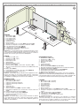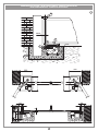
1
CARDIN ELETTRONICA spa
Via Raffaello, 36
31020 San Vendemiano (TV) Italy
Tel:
+39/0438.404011-401818
Fax:
+39/0438.401831
email (Italian): [email protected]
email (Europe): [email protected]
Http:
www.cardin.it
HL
24Vdc
Motors
Instruction manual
Series
Model
Date
ZVL480.01
HL
2524ESB-1824ESB
13-09-2005
Questo prodotto è stato testato e collaudato nei laboratori della casa costruttrice, la quale ne ha verificato la
perfetta corrispondenza delle caratteristiche con quelle richieste dalla normativa vigente. This product has been
tried and tested in the manufacturer's laboratory who have verified that the product conforms in every aspect to
the safety standards in force. Ce produit a été testé et essayé dans les laboratoires du fabriquant. Pour l'installer
suivre attentivement les instructions fournies. Dieses Produkt wurde in den Werkstätten der Herstellerfirma
auf die perfekte Übereinstimmung ihrer Eigenschaften mit den von den geltenden Normen vorgeschriebenen
getestet und geprüft. Este producto ha sido probado y ensayado en los laboratorios del fabricante, que ha
comprobado la perfecta correspondencia de sus características con las contempladas por la normativa vigente.
AUTOMAZIONE INTERRATA PER CANCELLI A BATTENTE CON MOTORE IN CORRENTE CONTINUA
UNDERGROUND AUTOMATION FOR HINGED GATES WITH A DC POWERED MOTOR
AUTOMATISME enterre POUR PORTAILS BATTANTS AVEC MOTEUR À COURANT CONTINU
UNTERFLUR-DREHTORANTRIEBE MIT GLEICHSTROMMOTOR
AUTOMATIZACIÓN enTERRADA PARA CANCILLAS BATIENTES CON MOTOR DE CORRIENTE CONTINUA
24 Vdc Motors 800/HL2524ESB
800/HL1824ESB
806/HLCF1
806/HLCF18
FRANÇAIS
ATTENTION! Avant de commencer la pose, lire attentivement les instructions!
Type d’installation
Schéma de montage
Schéma électrique (exemple d’installation)
Consignes importants
Instructions pour l’installation
Déverrouillage manuel
Branchement électrique
Procédé de programmation
Menu de visualisation
Commande via radio
Modes de fonctionnement
Fonctionnement à batterie
Indications de l’afficheur
Caractéristiques techniques
ITALIANO
Pagina
Pagine
Pagina
Pagina
Pagina
Pagina
Pagine
Pagina
Pagina
Pagina
Pagine
Pagina
Pagina
Pagina
ACHTUNG! Bevor mit der Installation begonnen wird,
sollte die Anleitung aufmerksam gelesen werden.
Anlagenart
Montageschemen
Elektrischer Schaltplan (Anlagenart)
Wichtige Hinweise
Installationsanleitung
Manuelle Entriegelung
Elektrischer Anschluss
Programmierverfahren
Anzeigemenü
Funkbefehl
Betriebsmodus
Batteriebetrieb
Displayanzeigen
Technische Eigenschaften
2
3-7
8
9
9
10
10-11
12
13
14
14-15
15
16
20
ENGLISH
ZVL480.01 Mod: 26-09-2008
Display mode
Remote control
Function modes
Battery powered operation
Indications on the display
Technical specifications
Seite
Seite
Seite
Seite
Seiten
Seite
Seiten
Seite
Seite
Seite
Seiten
Seite
Seite
Seite
2
3-7
8
33
33-34
34
34-35
36
37
38
38-39
39
40
52
ESPAÑOL
ATTENTION! Before installing this device read the
following instructions carefully!
Installation example
Assembly
Wiring diagram (installation example)
Important remarks
Installation instructions
Manual release mechanism
Electrical connection
Programming procedure
2
3-7
8
25
25-26
26
26-27
28
29
30
30-31
31
32
52
DEUTSCH
ATTENZIONE! Prima di iniziare l'installazione leggere
le istruzioni attentamente!
Impianto tipo
Schemi di montaggio
Schema elettrico (impianto tipo)
Avvertenze importanti
Istruzione per l’installazione
Sblocco manuale
Collegamento elettrico
Procedura di programmazione
Menu di visualizzazione
Comando via radio
Modalità di funzionamento
Funzionamento a batteria
Indicazioni del display
Caratteristiche tecniche
Page
Pages
Page
Page
Pages
Page
Pages
Page
Page
Page
Pages
Page
Page
Page
Page
Pages
Page
Page
Pages
Page
Pages
Page
Page
Page
Pages
Page
Page
Page
¡ATENCIÓN! Antes de iniciar la instalación del sistema,
leer atentamente las instrucciones.
2
3-7
8
11
17-18
18
18-19
20
21
22
22-23
23
24
52
Instalación estándar
Esquemas de montaje
Esquema eléctrico (instalación estándar)
Advertencias importantes
Instrucciones para la instalación
Desbloqueo manual
Conexionado eléctrico
Procedimiento de programación
Menú de visualización
Mando vía radio
Modalidad de funcionamiento
Funcionamiento por batería
Indicaciones en el display
Datos técnicas
1
Página
Páginas
Página
Página
Páginas
Página
Páginas
Página
Página
Página
Páginas
Página
Página
Página
2
3-7
8
41
41-42
42
42-43
44
45
46
46-47
47
48
52
1
Description : prodotti Technocity (lamp. fotocellule ecc.)
INSTALLAZIONE TIPO HL2524
4
5
8
1
3
7
6
11
LEGENDA
1 Motoriduttore (SX)
2 Motoriduttore (DX)
12
3 Fotocellula interna
4 Fotocellula esterna
5 Lampeggiatore
6 Selettore a chiave
7 Elettroserratura
8 Antenna esterna (Cavo coassiale RG58 Impedenza 50Ω)
9 Interruttore onnipolare con apertura contatti min. 3 mm
10 Cavo alimentazione principale 230 Vac
11 Canalatura per cavo Cardin CABPC10
12 Canalatura per collegamenti a bassa tensione
13 Programmatore elettronico
Attenzione: Lo schema rappresentato è puramente indicativo e viene
fornito come base di lavoro al fine di consentire una scelta dei componenti elettronici Cardin da utilizzare. Detto schema non costituisce
pertanto vincolo alcuno per l'esecuzione dell'impianto
LEGEND
1
2
3
4
5
6
7
8
9
Geared motor (SX - left)
Geared motor (DX - right)
Internal photocells
External photocells
Warning lights
Mechanical selector switch
Electric locking device
External antenna (RG58 coaxial cable - impedance 50Ω)
All-pole circuit breaker with a minimum of 3 mm between the
contacts
10 Mains cable 230 Vac
11 Channelling for the Cardin connection cable CABPC10
12 Channelling route for low voltage wires
13 Electronic programmer
Attention: The drawing is purely indicative and is supplied as a working base from which to choose the Cardin electronic components
making up the installation. This drawing therefore does not lay down
any obligations regarding the execution of the installation.
NOMENCLATURE
1
2
3
4
5
6
7
8
9
Motoréducteur (SX - gauche)
Motoréducteur (SX - droit)
Cellule photoélectrique intérieure
Cellule photoélectrique extérieure
Clignoteur
Sélecteur à clé
Serrure électrique
Antenne (Câble coaxial RG58 - Impédance 50Ω)
Interrupteur omnipolaire avec ouverture des contacts d'au moins
3 mm.
10 Câble d’alimentation principale 230 Vac
11 Chemin de câble spécial Cardin CABPC10
12 Chemin pour branchement basse tension
13 Armoire électronique
Attention: le schéma, diffusé à titre purement indicatif, est destiné
à vous aider dans le choix des composants électroniques Cardin à
utiliser. Par conséquent, il n'a aucune valeur obligatoire quant à la
réalisation de l'installation.
2
23
13
10
0V
-50
Hz
9
Zeichenerklärung
1 Getriebemotor (SX - links)
2 Getriebemotor (DX - rechts)
3 Interne Lichtschranke
4 Externe Lichtschranke
5 Blinklicht
6 Schlüsselschalter
7 Elektroverriegelung
8 Antenne (Koaxialkabel RG58 Impedanz 50Ω)
9 Allpoliger Schalter mit Kontaktenabstand von mindestens 3 mm
10 Hauptversorgungskabel 230 Vac
11 Kanalverlauf für Verbindungskabel Cardin CABPC10
12 Kanalverlauf für Anschluss auf Niederspannung
13 Elektronische Steuereinheit
Achtung: Bei dem dargestellten Plan handelt es sich nur um ungefähre
Angaben und er wird als Arbeitsgrundlage geliefert, um eine Auswahl der
zu benutzenden elektronischen Komponenten von Cardin zu erlauben. Der
besagte Plan ist daher für die Ausführung der Anlage nicht bindend.
LEYENDA
1
2
3
4
5
6
7
8
9
Motorreductor (SX - izquierda)
Motorreductor (SX - derecha)
Fotocélula interior
Fotocélula exterior
Relampagueador
Selector con llave
Electrocerradura
Antena exterior (Cable coaxial RG58 Impedancia 50Ω)
Interruptor omnipolar con apertura entre los contactos de 3 mm. como
mínimo.
10 Cable de alimentación principal 230 Vac
11 Canaleta para cable CABPC10 Cardin
12 Canaleta para el conexionado a baja tensión
13 Centralita electrónica
Atención: La pantalla que se muestra es sólo indicativa y se suministra
como base de trabajo, con el fin de permitir una elección de los componentes electrónicos Cardin por utilizar; en consecuencia, dicho esquema
no constituye vínculo alguno para la ejecución del sistema.
2
All rights reserved. Unauthorised copying or use of the information contained in this document is punishable by law
Drawing number : DI0447
Product Code : HL2524
ESEMPIO D'INSTALLAZIONE - Installation example - Exemple d'installation - Anlagenart - INSTALACIÓN ESTÁNDAR
All rights reserved. Unauthorised copying or use of the information contained in this document is punishable by law
SCHEMA DI MONTAGGIO motoriduttore - GEARED MOTOR ASSEMBLY - SCHÉMA DE MONTAGE DU motorÉduCtor
MONTAGEschema getriebemotor - ESQUEMA DE MONTAJE motorreductor
800/HL2524ESB
2
F
P
H
M
L
N
E
AT T E N Z I O N E ! - AT T E N T I O N ! - AT T E N T I O N ! - A C H T U N G ! - ¡ C U I D A D O !
Prima di collocare la cassetta all'interno dello scavo e di avvolgerla di calcestruzzo inserire le 6 viti "E" con testa tonda nelle rispettive sedi quadre ricavate sul fondo della cassetta, come indicato, e fissarle utilizzando dadi e rondelle in dotazione che poi serviranno per il fissaggio del motoriduttore.
Description : Accessori per l'interrato (sphere)
Drawing number : DM753
Before placing the embedding case inside the excavation and covering it with concrete, make sure you have inserted the 6 round-headed screws "E"
Code :square
HL2524ESB
intoProduct
their respective
holes on the bottom of the case and fastened them down using the supplied nuts and washers as shown in the drawing.
HL2524ESB
P.J.Heath
Draft
Avant
de :placer
le caissonDate
dans :le14-09-2005
puits bétonné et de le sceller avec du béton, introduire les 6 vis "E" à tête ronde dans les perforations carrées,
pratiquées
fond du caisson,
comme
indiqué
figure, et les
serrer
fond
en utilisant
les écrous
et les rondelles
fournis en dotation et prévus pour
CARDINau
ELETTRONICA
S.p.A
- 31020
San en
Vendemiano
(TV)
Italy à- via
Raffaello,
36 Tel:
0438/401818
Fax: 0438/401831
bloquer successivement le motoréducteur.
Bevor der Kasten in die Aushebung gelegt und mit Beton umgossen wird, müssen die 6 Rundkopf-Schrauben "E" in die entsprechenden Vierkantlöcher im Kastenboden wie aufgezeigt eingesetzt und mit den mitgelieferten Muttern und Unterlegscheiben befestigt werden. Diese Schrauben dienen
später für die Befestigung des Getriebemotors.
Antes de colocar la caja dentro de la excavación y rodearla de hormigón, introducir los 6 tornillos "E" con cabeza redonda en los alojamientos cuadrados correspondientes, conseguidos en el fondo de la caja, según lo que está indicado, y fijarlos utilizando las tuercas y arandelas suministradas
que luego servirán para fijar el motorreductor.
3
All rights reserved. Unauthorised copying or use of the information contained in this document is punishable by law
SCHEMA DI MONTAGGIO motoriduttore - GEARED MOTOR ASSEMBLY - SCHÉMA DE MONTAGE DU motorÉduCtor
MONTAGEschema getriebemotor - ESQUEMA DE MONTAJE motorreductor
800/HL1824ESB
3
H
A
C
B
G
P
Dett. 1
k
E
F
D
AT T E N Z I O N E ! - AT T E N T I O N ! - AT T E N T I O N ! - A C H T U N G ! - ¡ C U I D A D O !
Accessori inserire
per l'interrata
Drawing
numberall'interno
: DM795dello scavo e di Description
Prima di collocare
la cassetta
avvolgerla di:calcestruzzo
le 6 viti "E" con testa tonda nelle rispettive sedi quadre ricavate sul fondo della cassetta, come indicato, e fissarle utilizzando dadi e rondelle in dotazione che poi serviranno per il fissaggio del motoriduttore.
Product Code : HL251
HL251
Before placing
the :embedding
inside
the excavation and covering it with concrete, make sure you have inserted the 6 round-headed screws "E"
Date
: 07-02-2008
P.J.Heath case
Draft
into their respective square holes on the bottom of the case and fastened them down using the supplied nuts and washers as shown in the drawing.
CARDIN ELETTRONICA S.p.A - 31020 San Vendemiano (TV) Italy - via Raffaello, 36 Tel: 0438/401818 Fax: 0438/401831
Avant de placer le caisson dans le puits bétonné et de le sceller avec du béton, introduire les 6 vis "E" à tête ronde dans les perforations carrées,
pratiquées au fond du caisson, comme indiqué en figure, et les serrer à fond en utilisant les écrous et les rondelles fournis en dotation et prévus pour
bloquer successivement le motoréducteur.
Bevor der Kasten in die Aushebung gelegt und mit Beton umgossen wird, müssen die 6 Rundkopf-Schrauben "E" in die entsprechenden Vierkantlöcher im Kastenboden wie aufgezeigt eingesetzt und mit den mitgelieferten Muttern und Unterlegscheiben befestigt werden. Diese Schrauben dienen
später für die Befestigung des Getriebemotors.
Antes de colocar la caja dentro de la excavación y rodearla de hormigón, introducir los 6 tornillos "E" con cabeza redonda en los alojamientos cuadrados correspondientes, conseguidos en el fondo de la caja, según lo que está indicado, y fijarlos utilizando las tuercas y arandelas suministradas
que luego servirán para fijar el motorreductor.
4
Dimensioni d’ingombro - External dimensions - Dimensions d’encombrement
AuSSenabmessungen - DIMENSIONES MÁXIMAS
64
366
4
43
12
55
100
159
59
55
25
All rights reserved. Unauthorised copying or use of the information contained in this document is punishable by law
401
332
LIMITI D’IMPIEGO - limits of use - CONTRAINTES D'UTILISATION - ANWENDUNGSGRENZEN - LIMITES DE EMPLEO
5
1
1
SCALA:
Description : Prodotti Technocity
Drawing number : DI0104
Dimensioni d'ingombro
Product Code : HL
Draft : P.J.Heath
Date : 19-11-98
CARDIN ELETTRONICA S.p.A - 31020 San Vendemiano (TV) Italy - via Raffaello, 36 Tel: 0438/401818 Fax: 0438/401831
1
140
140
1
180
180
SCALA:
5
ESEMPIO D’INSTALLAZIONE - INSTALLATION EXAMPLE - EXEMPLE D'INSTALLATION
INSTALLIERUNGSBEISPEIL - EJEMPLO DE INSTALACIÓN
6
D
64mm
All rights reserved. Unauthorised copying
or use of the information contained in this document is punishable by law
F
G
3mm
I
B
C
E
A
SCALA:
332
332
Description : Prodotti Technocity
Drawing number : DI0106
Scavo per cassa di fondazione
Product Code : HL
Draft : P.J.Heath
Date : 19-11-98
401
401
CARDIN ELETTRONICA S.p.A - 31020 San Vendemiano (TV) Italy - via Raffaello, 36 Tel: 0438/401818 Fax: 0438/401831
3
64
159
100
59
64
6
MONTAGGIO DISPOSITIVO 180° - ASSEMBLING THE 180° DEVICE - MONTAGE DU DISPOSITIF 180°
MONTAGE VORRICHTUNG 180° - MONTAJE DISPOSITIVO 180°
7
Pos. 0
Pos. 180
Z
W
x
REGOLAZIONE FINECORSA MECCANICI - ADJUSTING THE MECHANICAL TRAVEL LIMITS - RÉGLAGE DES FINS DE COURSE
MÉCANIQUES - EINSTELLUNG DES MECHANISCHEN ENDANSCHLAGES - REGULACIÓN TOPES MECÁNICOS
R
ved. Unauthorised copying or use of the information
contained
in Unauthorised
this documentcopying
is punishable
law information contained 8
All rights
reserved.
or use by
of the
in this doc
T
M
N
Drawing number : DM325
Product Code : HL251
S
Draft : P.J.Heath
Description : Accessori per l'interrata (FIG.2)
HL251
T
Date : 08-01-98
CARDIN ELETTRONICA S.p.A - 31020 San Vendemiano (TV) Italy - via Raffaello, 36 Tel: 0438/401818 Fax: 0438/401831
SBLOCCO MANUALE - MANUAL RELEASE MECHANISM - DÉVERROUILLAGE MANUEL
MANUELLE ENTRIEGELUNG - DESBLOQUEO MANUAL
9
Q
O
J
H
SCALA:
Drawing number :
7
Description : Prodotti Technocity
SCHEMA ELETTRICO IMPIANTO TIPO - STANDARD WIRING DIAGRAM - SCHÉMA ÉLECTRIQUE DE L'EXEMPLE
D'INSTALLATION - ELEKTRISCHER SCHALTPLAN ANLAGENART - ESQUEMA ELÉCTRICO INSTALACIÓN ESTÁNDAR
10
CC242ESSB
All rights reserved. Unauthorised copying or use of the information contained in this document is punishable by law
B)
A)
D
CH
J3
D
CH
C
CH
B
CH
A
CH
MM
C
CH HB
C
A
CH
24LC16
ANS400
10
F2
F4
F3
L5
J3
L1
4A
L3
B1
L2
J4
4A
L7
LS
FTCI
COLORATION
DES CÂBLAGES
Bleu
Vert
Gris
Jaune
Rouge
Noir
TFTI
TFTS
SAP
ELS
P3
12
M1
ENCODER 1
Bk Rd Bl Gr Gy Yw
1
2
3
4
5
6
1
PC
Drawing number : DI0516
Product Code : CC242C (PRG)
2
LS
HL2524ESB M2
HL1824ESB M2
M2
ENCODER 2
1
CSP (N.C)
FTCS (N.C)
FTCI (N.C)
12
TB (N.C)
11
CMN
10
TD (N.O)
1
9
TAL (N.O)
2
LC/CH2
TC (N.O)
8
13
14
15
16
17
18
19
20
21
22
23
24
25
26
2
3
0 12V 24V
FTC-Tx
1
2
3
24V 12V
4
5
6
NA
C
2
1
0
NA
NC
C
SEL
NC
FTC-Rx
Bk Rd Bl Gr Gy Yw
2
3
4
5
EMRG 2
TA (N.O)
7
CMN
EMRG 1
OUT 30Vdc
6
1
3
4A
F5
LP
HL2524ESB M1
HL1824ESB M1
12
3
CMN
5
J6
CTRL 30Vdc
4
CSER
Pos.1 Pos.2
ENCODER 2
Bl Gr Gy Yw
3
3
LS
2
12
3
CMN
1
D1
Pos.1 Pos.2
L4
LP
6
M2
12
P2
CMN
5
LP
COLORACIÓN CABLEADOS
Azul
Verde
Gris
Amarillo
Rojo
Negro
ENCODER 1
Bl Gr Gy Yw
4
PLP
ELS 12V
COLOUR CODE
CODE
Blue
Green
Grey
Yellow
Red
Black
RA
CMN
10
Bl
Gr
Gy
Yw
Rd
Bk
KABELFARBEN
Blau
Grün
Grau
Gelb
Rot
Schwarz
3
L12
P1
ON
TD
1 2 3 4 5 6 7 8 9 10
COLORE
CABLAGGI
Blu
Verde
Grigio
Giallo
Rosso
Nero
2
L10
4A
Bl
Gr
Gy
Yw
Rd
Bk
1
L11
J5
DS1
F1
Collegamento motori/encoder a 4 fili
Connecting motor/4-wire encoder
Branchement moeteur/encoder à 4 fils
Anschluss der Motor/encoder mit 4 Drähten
Conexionado motor/encoder con 4 conductores
M1
L9
L6
J2
10
L8
27 28 29
J1
CS1283
DI 0516
R1
31 30
4A
4A
10
6
PC
Description : Collegamenti scheda base
CENTRALINA 82 MOTORI CC CON ENCODER
3
2
1
TB
2
1
CSP
Avvertenze importanti
Avvertenze importanti
Avvertenze importanti
LEGGERE ATTENTAMENTE LE SEGUENTI AVVERTENZE PRIMA DI PROCEDERE ALL’INSTALLAZIONE. PREDISPOSTE NEL TESTO. IL MANCATO
STARE PARTICOLARE ATTENZIONE A TUTTE LE SEGNALAZIONI
RISPETTO DI QUESTE POTREBBE COMPROMETTERE IL BUON FUNZIONAMENTO DEL SISTEMA E CREARE
SITUAZIONI DI PERICOLO GRAVE PER L'OPERATORE E GLI UTILIZZATORI DEL SISTEMA STESSO.
• Il presente manuale si rivolge a persone abilitate all'installazione di "apparecchi
utilizzatori di energia elettrica" e richiede una buona conoscenza della tecnica,
esercitata in forma professionale e della normativa vigente.
I materiali usati devono essere certificati e risultare idonei alle condizioni ambientali
di installazione.
• Le operazioni di manutenzione devono essere eseguite da personale qualificato.
Prima di eseguire qualsiasi operazione di pulizia o di manutenzione, disinserire
l'apparecchiatura dalla rete di alimentazione elettrica.
• Le apparecchiature qui descritte dovranno essere destinate solo all'uso per il quale
sono state espressamente concepite:
"La motorizzazione di cancelli a battente ad una o due ante".
lunghezza max. 3 m - peso max. 350 kg.
• L'applicazione è possibile sia a sx che a dx della luce passaggio.
L'utilizzo dei prodotti e la loro destinazione ad usi diversi da quelli previsti e/o
consigliati, non è stata sperimentata dal costruttore, pertanto i lavori eseguiti sono
sotto la completa responsabilità dell'installatore.
AVVERTENZE PER L'UTENTE
Attenzione! Solo per clienti dell’EU - Marcatura WEEE.
Il simbolo indica che il prodotto alla fine della propria vita utile deve
essere raccolto separatamente dagli altri rifiuti. L’utente dovrà pertanto
conferire l’apparecchiatura agli idonei centri di raccolta differenziata
dei rifiuti elettronici ed elettrici, oppure riconsegnarla al rivenditore al
momento dell’acquisto di una nuova apparecchiatura di tipo equivalente, in ragione di uno a uno.
L’adeguata raccolta differenziata per l’avvio al riciclaggio, al trattamento e allo
smaltimento ambientalmente compatibile contribuisce ad evitare possibili effetti
negativi sull’ambiente e sulla salute e favorisce il riciclo dei materiali. Lo smaltimento abusivo del prodotto da parte del detentore comporta l’applicazione delle
sanzioni amministrative previste dalla normativa vigente nello Stato Comunitario
di appartenenza.
Durante la manovra si deve controllare il movimento del cancello e azionare il dispositivo
di arresto immediato (STOP) in caso di pericolo. In caso di emergenza il cancello può
essere sbloccato manualmente utilizzando l'apposita chiave di sblocco in dotazione
(vedi sblocco manuale pag. 7). Controllare periodicamente lo stato di usura dei perni
ed eventualmente ingrassare le parti in moto usando lubrificanti che mantengano uguali
caratteristiche di attrito nel tempo e adatti a funzionare tra -20 e +70°C. Verificare
periodicamente il funzionamento delle sicurezze (fotocellule ecc.) Le eventuali riparazioni devono essere eseguite da personale specializzato usando materiali originali
e certificati. L'uso dell'automazione non è idoneo all'azionamento in continuo, bensì
deve essere regolato in base ai vari modelli (vedi caratteristiche tecniche pag. 52).
Attenzione! Installare sempre la battuta di arresto meccanico delle ante
(fig. 5 pos. 1).
CONSIDERAZIONI GENERALI DI SICUREZZA
È responsabilità dell’installatore verificare le seguenti condizioni di sicurezza:
1) L’installazione deve essere sufficientemente lontana dalla strada in modo da non
costituire pericolo per la circolazione.
2) L’operatore deve essere installato all’interno della proprietà ed il cancello non deve
aprirsi verso l’area pubblica.
3) Il cancello motorizzato è principalmente adibito al passaggio di vetture. Dove
possibile installare per pedoni un ingresso separato.
4) I comandi devono essere posti in vista, ad un altezza compresa tra 1,5 m e 1,8
m, ma non entro il raggio d’azione del cancello. Inoltre quelli installati all’esterno
devono essere protetti da una sicurezza tale da prevenire l’uso non autorizzato.
5) È buona norma segnalare l’automazione con targhe di avvertenza
ATTENZIONE
(simili a quella in figura) che devono essere facilmente visibili. Qua- APERTURA AUTOMATICA
NON
AVVICINARSI
lora l’automazione sia adibita al solo passaggio di veicoli dovranno
essere poste due targhe di avvertenza di divieto di transito pedonale
(una all’interno, una all’esterno).
6) Rendere consapevole l’utente che bambini o animali domestici non
devono giocare o sostare nei pressi del cancello. Se necessario
indicarlo in targa.
7) Qualora l’anta completamente aperta vada ad avvicinarsi ad una
struttura fissa lasciando uno spazio ≤ 500 mm, tale spazio deve essere protetto
con una costa sensibile antischiacciamento (vedi figura 1, dett.11).
8) Per qualsiasi dubbio a riguardo della sicurezza dell’installazione, non procedere ma
rivolgersi al distributore del prodotto.
ISTRUZIONI PER L'INSTALLAZIONE
I comandi minimi che possono essere installati sono APERTURA-STOP-CHIUSURA,
tali comandi devono essere posti in un luogo non accessibile a bambini o minori e
fuori dal raggio d’azione del cancello. Prima di procedere all'esecuzione dell'impianto
verificare che la struttura da automatizzare sia in perfetta efficienza nelle sue parti fisse
e mobili e realizzata in conformità alla normativa vigente. A tal fine accertarsi della
sufficiente rigidità del telo cancello (se necessario intervenire con rinforzi sulla struttura)
e del buon funzionamento dei perni (si consiglia comunque di lubrificare tutte le parti
in movimento usando lubrificanti che mantengano uguali caratteristiche di attrito nel
tempo e adatti a funzionare tra -20 e +70°C).
• Controllare i franchi di sicurezza tra parti fisse e parti mobili:
- lasciare uno spazio minimo di 30 mm tra il cancello ed il pilastro di supporto per
tutta l’altezza e per tutto l’arco di apertura del cancello;
- assicurarsi che lo spazio tra il cancello ed il pavimento non superi mai 30 mm per
tutto l’arco di apertura del cancello.
• La superficie delle ante non deve presentare aperture tali da permettere il passaggio
della mano o del piede di persone.
• Controllare l'esatto posizionamento di perni e cerniere, il loro buon stato di mantenimento e lubrificazione (importante che la cerniera superiore e quella inferiore
siano a piombo tra loro).
• Prevedere il percorso dei cavi secondo le necessità di applicazione dei dispositivi
di comando e sicurezza. (ved. impianto tipo fig.1 pag.2).
• Controllare che l’operatore sia proporzionato alle dimensioni del cancello e alla
frequenza d’uso (intermittenza di lavoro, pag. 52).
NON PERMETTERE A BAMBINI O AD
ANIMALI DOMESTICI DI SOSTARE NEL
RAGGIO D'AZIONE DEL CANCELLO
Descrizione tecnica
800/HL2524ESB Motoriduttore autobloccante, apertura anta max 110°.
806/HLCF1Z
Cassa di fondazione in acciaio zincato con leve per apertura anta
max 110°
806/HLCF1
Cassa di fondazione in acciaio zincato con trattamento a cataforesi
e leve per apertura anta max 110°
800/HL1824ESB Motoriduttore autobloccante, apertura anta 180°- 360°.
806/HLCF18Z
Cassa di fondazione in acciaio zincato con accessori per apertura
anta 180°-360°
806/HLCF18
Cassa di fondazione in acciaio zincato con con trattamento a
cataforesi ed accessori per apertura anta 180°-360°
806/HLCA140 Kit leva accessoria per apertura a 140°
• Monoblocco motoriduttore con encoder incorporato.
• Motore alimentato con tensione max. 28 Vdc.
• Riduttore irreversibile montato su cassa in pressofusione di alluminio con lubrificazione a grasso fluido permanente.
• Guarnizioni in gomma a tenuta d'olio.
• Sblocco manuale a chiave.
• Cassetta da interrare in acciaio pressopiegato, zincato a caldo;
- scatola sblocco in alluminio pressofuso.
• Leve di trasmissione in acciaio zincato;
- staffa di fissaggio cancello in acciaio zincato.
Procedura di montaggio
• Scegliere la posizione della cassetta da interrare in base alla posizione del perno
d'incernieramento del cancello rispetto al pilastro e al tipo di apertura (90°-110°180°) da realizzare (fig. 5).
• Sistemare una battuta di arresto meccanico in chiusura (det. 1, fig. 5).
• Eseguire uno scavo di fondazione "A" (fig. 6) nella posizione prescelta in base
alla dimensione della cassetta e prevedere uno scarico per l'acqua piovana
utilizzando il foro "B".
• Prevedere il percorso della canalatura per i cavi di collegamento elettrico utilizzando il foro "C".
• Inserire le sei viti con testa tonda "E" nelle rispettive sedi quadre ricavate sul
fondo della cassetta e bloccarle utilizzando le rondelle e i dadi previsti per il
successivo bloccaggio del motoriduttore.
• Collocare la cassetta all'interno dello scavo con il perno perpendicolare rispetto
al cardine superiore "D" e avvolgerla di calcestruzzo, curare la messa in bolla e la
corretta posizione del bordo superiore che dovrà sporgere di 3 mm dal livello terra.
- Togliere i dadi e le rondelle utilizzati per bloccare i bulloni a testa tonda sul fondo
della cassetta.
- Inserire il motoriduttore nella cassetta e fissarlo a quattro dei sei perni filettati "E"
premontati sul fondo della stessa (per il modello HL1824ESB vedi pag. 10).
- Fissare il piatto superiore "F" completo di sblocco all'anta del cancello con
saldatura robusta, calcolando che il perno "G" della leva stessa deve risultare in
asse col cardine superiore "D".
ACCESSORI
980/XLSE11C - Elettroserratura 12 Vac/dc
9
- Quindi, a seconda del modello, procedere come segue:
Avvertenze importanti
• Mod. 800/HL2524ESB con cassa 806/HLCF1 (fig. 2)
- Posizionare la leva cancello "H" sul perno della cassetta dopo aver ingrassato il
perno stesso e inserire all'interno della leva la sfera di articolazione "L".
- Montare l'anta inserendo il perno della leva "F" nella rispettiva sede della leva
cancello "H" dopo aver ingrassato le parti e fissare il cardine superiore "D" (fig. 6).
- Montare la biella di trasmissione "M" tra la leva "N" del motoriduttore e la leva "H"
del cancello avendo cura di ingrassare bene i perni.
- Portare lentamente l'anta ad allinearsi con la leva cancello "H" (fig. 9) in modo
che il meccanismo di sblocco "O" vada ad impegnarsi con lo scrocco della leva
cancello "H". L’aggancio è automatico e non richiede l’uso della chiave.
- Chiudere il coperchio "P" con le due viti in dotazione.
Attenzione! In nessun punto della scheda del programmatore è presente
la tensione a 230 Vac: si ha solamente la bassissima tensione di sicurezza.
Per la conformità alla normativa sulla sicurezza elettrica, è proibito collegare
i morsetti 9 e 10 direttamente ad un circuito dove sia applicata una tensione
superiore a 30 Vac/dc.
Attenzione! Per il corretto funzionamento del programmatore è necessario
che le batterie incorporate siano in buono stato: in assenza di tensione di
rete, se le batterie sono scariche, si verifica la perdita del controllo della
posizione dell'anta con conseguente segnalazione di allarme e necessità di
riposizionamento. Controllare quindi l'efficienza delle batterie ogni sei mesi.
(vedi pagina 15 "Verifica delle batterie").
• Dopo aver installato il dispositivo, e prima di dare tensione alla centralina,
verificare che il movimento del cancello eseguito in modo manuale (con
motore sbloccato) non abbia punti di resistenza particolarmente marcata.
• L’uscita per l’alimentazione dei carichi controllati (morsetto 15) è
pensata per ridurre il consumo della batteria in assenza di tensione
di rete; collegare pertanto le fotocellule ed i dispositivi di sicurezza.
• Quando arriva un comando radio (o via filo) il programmatore dà tensione all’uscita CTRL 30 Vdc, e se le sicurezze risultano a riposo attiva il
motore.
• La connessione all’uscita per i "carichi controllati" permette anche di
eseguire l’autotest (abilitabile mediante i DIP 7 e 8) per la verifica del corretto
funzionamento dei dispositivi di sicurezza.
• La presenza del sensore di corrente non elimina l’obbligo di installare le
fotocellule o altri dispositivi di sicurezza previsti dalle normative vigenti.
• Accertarsi, prima di eseguire il collegamento elettrico, che la tensione e
la frequenza riportate sulla targhetta caratteristiche corrispondano a quelle
dell'impianto di alimentazione.
• Tra la centralina di comando e la rete deve essere interposto un interruttore
onnipolare, con distanza di apertura tra i contatti di almeno 3 mm.
• Non utilizzare cavo con conduttori in alluminio; non stagnare l’estremità
dei cavi da inserire in morsettiera; utilizzare cavo con marcatura T min 85°C
resistente agli agenti atmosferici.
• I conduttori dovranno essere adeguatamente fissati in prossimità della
morsettiera in modo che tale fissaggio serri sia l’isolamento che il conduttore
(è sufficiente una fascetta).
REGOLAZIONE FINE CORSA MECCANICO
(solo per mod. 800/HL2524ESB con cassa 806/HLCF1 - fig. 8)
Il finecorsa meccanico regolabile previsto tra la leva "N" del motoriduttore e la sporgenza
"R" interna alla cassetta deve essere utilizzato al fine di non caricare eccessivamente
l'anta in chiusura e di permettere un regolare funzionamento del meccanismo di sblocco.
Per la regolazione procedere come segue:
- Portare l'anta "S" in battuta contro il fermo meccanico cancello e staccare istantaneamente l'alimentazione al motore.
- Far fuoriuscire la vite "T" dalla leva "N" fino a portarla in battuta contro il fermo "R"
in questo modo la biella "M" mantiene chiuso il cancello senza esercitare sforzi
eccessivi su di esso.
- Utilizzare la vite e dado "T" in dotazione per effettuare un fermo meccanico regolabile
in apertura.
•
•
-
-
-
-
-
-
-
-
-
-
-
-
Mod. 800/HL1824ESB con cassa 806/HLCF18 (fig. 3)
Per facilitare il montaggio del meccanismo sulla cassetta:
Togliere la squadretta "F" dalla sua posizione (sulla cassa).
Separare provvisoriamente dal motore la piastra tendicatena "B" togliendo le viti
"K" (dett. 1).
Sulla cassetta ingrassare il perno di rotazione e posizionare nell'apposita sede la
sfera d'acciaio "G".
Inserire il motoriduttore nella cassa rispettando la corretta posizione sui prigionieri
predisposti (fig. 7) fissandolo tenacemente utilizzando dadi e rondelle in dotazione.
Fissare sul motoriduttore (rispettando la posizione indicata) la piastra tendicatena
utilizzando le 6 viti in dotazione.
Montare la catena "C" facendo aderire una sua estremità in posizione "Z" (fig. 7) ai
denti della corona della leva "A". Leva cancello "A" in posizione 0° (fig .7).
Ruotare la leva di 180°, in tal modo l’estremità posizione "Z" della catena verrà
trascinata in posizione "W" così da poter essere collegata all’altra estremità tramite
la maglia di giunzione "C".
Tendere la catena agendo sulle viti di registro. Per eseguire tale operazione si consiglia
di portare l’anta in battuta meccanica nella posizione di 0° azionando il motoriduttore,
così facendo si mette in tiro il lato "X" e si scarica il lato "W" (fig. 7) della catena e
sarà facilitato l’azzeramento dei giochi. Serrare bene i dadi di bloccaggio "P".
Riposizionare la squadretta "F" nella sua posizione iniziale.
È buona norma ingrassare catena e perni periodicamente..
Portare lentamente l'anta ad allinearsi con la leva cancello "H" (fig. 9) in modo
che il meccanismo di sblocco "O" vada ad impegnarsi con lo scrocco della leva
cancello "H". L’aggancio è automatico e non richiede l’uso della chiave.
Chiudere il coperchio "P" con le due viti in dotazione.
COLLEGAMENTI ALIMENTAZIONE CENTRALINA 230 Vac
• Collegare i fili di comando e quelli provenienti dalle sicurezze.
• Portare l'alimentazione generale al programmatore collegandolo alla morsettiera a due vie che è già collegata al
primario del trasformatore.
N
L
PREPARAZIONE CAVO COLLEGAMENTO MOTORE
• Il kit contiene 10 metri di cavo a sei poli da tagliare secondo le esigenze dell'impianto.
• Aprire il vano di derivazione "T" fig. 3 e portare il cavo di collegamento.
• Svitare il tappo del pressacavo "PC" e far passare il cavo nel vano "T".
• Collegare i fili del motore "M1" e l'encoder "1" sulla morsettiera a sei vie.
• Rispettare scrupolosamente la sequenza di connessione dei motori alla centralina;
l’ordine dei morsetti 1...6 è identico sul motore e sulla centralina.
SBLOCCO MANUALE (fig. 9)
L'operazione di sblocco va fatta solamente a motore fermo, per mancanza di energia
elettrica. Per sbloccare l'anta del cancello munirsi della chiave in dotazione all'apparecchiatura.
Per sbloccare l’anta
- Spostare lo sportellino "Q" copriserratura.
- Inserire la chiave e ruotare di mezzo giro (180°), lo sgancio sarà immediato.Tale
operazione rende l’anta folle rispetto al meccanismo e quindi libera di ruotare
manualmente.
- Aprire l’anta esercitando una leggera spinta.
Per ribloccare l’anta
- Portare lentamente l’anta ad allinearsi con la leva cancello "H" in modo che il meccanismo di sblocco "O" vada ad impegnarsi con lo scrocco della leva cancello "H".
Il riaggancio è automatico e non richiede l’uso della chiave.
- È anche possibile fare ripartire il motoriduttore, il quale si andrà a riagganciare automaticamente all’anta.
Motore 1
1-2 3-4-5-6 Alimentazione motore 1
Ingressi per segnali encoder 1
Motore 2
1-2 3-4-5-6 Alimentazione motore 2
Ingressi per segnali encoder 2
• Serrare a fondo il tappo del pressocavo "PC".
PROGRAMMATORE ELETTRONICO
Programmatore per motori in corrente continua con encoder con ricevente incorporata,
che permette la memorizzazione di 300 codici utente. La decodifica è di tipo 'rolling
code', e la frequenza di funzionamento è di 433 MHz (S449).
La velocità di rotazione dei motori è controllata elettronicamente, con partenza lenta
e successivo incremento; la velocità viene ridotta con anticipo rispetto all'arrivo in
battuta, in modo da ottenere un arresto controllato.
La programmazione, eseguibile mediante un solo pulsante, permette la regolazione
del sensore di sforzo e della corsa totale della porta. L'intervento del sensore
antischiacciamento/anticonvogliamento causa l'inversione del moto.
Attenzione! Per garantire il grado di IP67 è fondamentale:
- chiudere a fondo il pressacavo "PC";
- posizionare correttamente la guarnizione sul vano morsettiera "T";
- posizionare il coperchio e serrare a fondo le quattro viti di chiusura.
• Ripetere l'operazione per il secondo motore ed il secondo encoder.
10
Collegamenti morsettiera
Nota (2) Il jumper "J6" seleziona il tipo di costa sensibile collegato al morsetto 24:
- in posizione 1 si seleziona la costa con contatto NC;
- in posizione 2 si seleziona la costa di sicurezza con contatto 8.2 kΩ;
Se si ponticella l'ingresso CSP, posizionare il jumper "J6" in posizione 1 (NC).
7
CMN comune per tutti gli ingressi/uscite
8
ELS uscita per elettroserratura (pilotata in continua) 12 Vdc – 15 W
9-10 LC-CH2 uscita (contatto puro, N.A.) per attivazione luce di cortesia (alimentata
a parte, Vmax = 30 Vac/dc: Imax = 1A) oppure per secondo canale radio. La
Tutti i contatti N.C. non utilizzati vanno ponticellati e di conseselezione viene fatta tramite jumper J5.
guenza i test sulle sicurezze corrispondenti (FTCI, FTCS – DIP7 e DIP8) devono
11 CMN Comune per tutti gli ingressi/uscite
essere disabilitati.
12 LP uscita lampeggiante 24 Vdc 25 W con attivazione intermittente (50%), 12,5
Se si vuole attivare il test sulle FTCI, FTCS sia la parte trasmittente che la parte riceW con attivazione fissa
vente di tale sicurezze vanno collegate ai carichi controllati (CTRL30Vdc). Si tenga
13 LS uscita lampada spia 24 Vdc 3W
presente che nel caso sia abilitato il test, tra la ricezione del comando e il moto delle
14 CMN comune per tutti gli ingressi/uscite
ante/a passa circa 1 secondo.
(1)
15 Uscita carichi esterni controllati 30 Vdc
Alimentare il circuito e verificare che lo stato dei LED di segnalazione sia come
16 CMN comune per tutti gli ingressi/uscite
segue:
17 Uscita carichi esterni 30 Vdc(1)
- L1 Alimentazione scheda
acceso
18 TA (N.A.) ingresso pulsante di apertura
- L2 Batteria sotto carica spento (3)
19 TC (N.A.) ingresso pulsante di chiusura
- L3 Errata connessione batteria
spento (4)
20 TAL (N.A.) ingresso pulsante di apertura limitata
21 TD (N.A.) ingresso pulsante comando sequenziale
- L4 Programmazione codici trasmettitori spento
22 CMN comune per tutti gli ingressi/uscite
- L5 Segnalazione tasto blocco "TB" acceso (5)
23 TB (N.C.) ingresso pulsante di blocco (all’apertura del contatto si interrompe
- L6 Segnalazione fotocellule d'inversione "FTCI"
acceso (5)
rights
Unauthorised
copying or use of the information contained in this document is punishable by law
il ciclo diAll
lavoro
finoreserved.
ad un nuovo
comando di moto)
- L7 Segnalazione fotocellule di stop "FTCS"
acceso (5)
24 CSP ingresso per costa sensibile. L'apertura del contatto inverte il moto sia
- L8 Segnalazione costa sensibile "CSP"
acceso (5)
nella fase di chiusura che nella fase di apertura(2)
-
L9
Segnalazione
tasto
di
apertura
(TA)
spento
25 FTCS (N.C.) ingresso per dispositivi di sicurezza (fotocellula di stop). L'aper- L10 Segnalazione tasto di chiusura (TC)
spento
tura del contatto blocca il moto; al ritorno nella condizione di riposo, dopo il
- L11 Segnalazione tasto di apertura limitata (TAL)
spento
tempo di pausa il moto riprenderà in chiusura (solo con richiusura automatica
- L12 Segnalazione comando sequenziale (TD/CH1)
spento
abilitata).
Nota (3) Acceso se le batterie sono sotto carica.
26 FTCI (N.C.) ingresso per dispositivi di sicurezza (fotocellula di inversione in
Nota (4) Nel caso sia acceso invertire immediatamente la connessione della
chiusura). L’apertura del contatto, conseguente all’intervento dei dispositivi
batteria.
di sicurezza, durante la fase di chiusura, attuerà l’inversione del moto.
Nota (5) I LED sono accesi se la relativa sicurezza non è attivata. Verificare che
27 EMRG2 (N.A.) ingresso pulsante per manovra di emergenza 2
l'attivazione delle sicurezze porti allo spegnimento del LED ad esse
28 EMRG1 (N.A.) ingresso pulsante per manovra di emergenza 1
associato.
29 CMN comune per i pulsanti di emergenza
30 Centrale antenna ricevitore radio (nel caso si utilizzi un’antenna esterna colNel caso in cui il LED verde di alimentazione "L1" non si accenda verificare
legarla con cavo coassiale RG58 imp. 50Ω)
lo stato dei fusibili ed il collegamento del cavo di alimentazione al primario del
31 Massa antenna ricevitore radio
trasformatore.
Nel caso in cui uno o più LED di sicurezza non si accendano verificare che i
Nota (1) La somma delle due uscite per carichi esterni non deve superare 10W.
contatti delle sicurezze non utilizzate siano ponticellate sulla morsettiera.
10
F2
J1
F4
J3
L1
L5
4A
L3
B1
MM
L2
F3
CS 1283
DC 0406
R1
31 30
4A
4A
10
J2
L9
L8
L11
P1
L6
J4
D1
L12
L10
4A
L7
B1
CSER
D1
DS1
F1
F2
F3
F4
F5
J1
LC/CH2
9
10
Product Code : CC24??????????
12
13
14
15
16
17
18
19
20
21
22
J2
J3
J4
J5
J6
MM
P1
P2
P3
R1
Nota (6)
Buzzer segnalazione modalità "via radio"
Connessione seriale (solo per diagnostica)
Display a LED a 6 cifre
Dip-switch di selezione
Fusibile a lama(6) 10A (protezione alimentazione motore)
Fusibile a lama(6) 10A (protezione motore modalità batteria)
Fusibile a lama(6) 4A (protezione circuito 24V)
Fusibile a lama(6) 4A (protezione circuito 24V modalità batteria)
Fusibile a lama(6) 4A (protezione elettroserratura)
Connessione batteria
Drawing number : DC0406
11
23
24
25
26
Connessione secondario trasformatore
Jumper abilitazione alla memorizzazione codici Tx via radio
Jumper selezione canale radio
Jumper selezione morsetti 9, 10 (luce di cortesia/CH2 radio)
Jumper selezione CSP NC/8.2 kΩ
Modulo di memoria codici TX
Tasto di programmazione (PROG)
Tasto di memorizzazione codici TX (MEMO)
Tasto di cancellazione codici TX (DEL)
Modulo RF, 433 MHz per trasmettitore S449
I fusibili a lama sono di tipo automotive (tensione max. 58V)
Description : Collegamenti scheda base
11
FTCI (N.C)
8
FTCS (N.C)
7
EMRG 1
EMRG 2
TB (N.C)
6
CMN
CSP (N.C)
5
CMN
4
TD (N.O)
4A
F5
ENCODER 2
Bl Gr Gy Yw
3
3
Pos.1 Pos.2
TAL (N.O)
2
12
3
TC (N.O)
1
12
TA (N.O)
6
P3
OUT 30Vdc
5
J6
CMN
4
L4
CTRL 30Vdc
3
3
Pos.1 Pos.2
CMN
2
ELS
P2
12
3
LS
1
M2
SAP
ELS 12V
M1
ENCODER 1
Bl Gr Gy Yw
TFTI
CMN
Blau
Grün
Grau
Gelb
FTCI
TFTS
CSER
12
LP
10
Bl
Gr
Gy
Yw
COLORACIÓN
CABLEADOS
Azul
Verde
Gris
Amarillo
LS
ON
KABELFARBEN
COLORATION
DES CÂBLAGES
Bleu
Vert
Gris
Jaune
LP
4A
Bl
Gr
Gy
Yw
COLOUR CODE
CODE
Blue
Green
Grey
Yellow
RA
PLP
1 2 3 4 5 6 7 8 9 10
Collegamento motori/encoder a 4 fili
Connecting motor/4-wire encoder
Branchement moteur/encodeur à 4 fils
Anschluss der Motor/Encoder mit 4 Drähten
Conexionado motores/encoder de 4 conductores
COLORE
CABLAGGI
Blu
Verde
Grigio
Giallo
J5
DS1
TD
27 28 29
F1
CMN
10
CENTRALINA 2 MOTORI CC CON ENCODER
Procedura di programmazione (Impostazioni del programmatore e del sensore di corrente)
• È obbligatoria la presenza delle battute di apertura e chiusura per entrambe le ante.
• Accertarsi che le sicurezze siano a riposo e che la scheda sia alimentata da rete: in caso contrario non si entra in programmazione.
• Selezionare nel "menu di visualizzazione" (pagina 13) il modello del motoriduttore utilizzato.
• Il sistema si configura automaticamente per il funzionamento a singola o doppia anta.
Impostazione dip-switch DS1
PREMERE IL TASTO PROG PER PIÙ
DI 4 SECONDI: COMPARE IL SIMBOLO
"PAUSE" CHE INDICA LA
PROGRAMMAZIONE DEL TEMPO DI PAUSA
ATTENZIONE: se si cambia l'impostazione dei dip, tale impostazione deve
essere memorizzata; premere dunque il tasto "PROG", sul display appare la
dicitura "dIP" segnalando l’avvenuta memorizzazione.
Comando sequenziale TD/CH1
ON
Dip 1 "ON" = Comando sequenziale "apre-chiude"
1 2 3 4 5 6
L’inversione del moto si ha solamente in fase di chiusura.
Dip 1 "OFF" = Comando sequenziale "apre-blocco-chiude-blocco"
Richiusura automatica (DIP 2)
Dip 2 "ON" = Richiusura automatica abilitata
Dip 2 "OFF" = Richiusura automatica disabilitata
ON
Prelampeggio (DIP 3)
Dip 3 "ON" = Prelampeggio inserito
Dip 3 "OFF" = Prelampeggio escluso
ON
Uscita lampeggiante (DIP 4)
Dip 4 "ON" = Uscita lampeggiante intermittente
Dip 4 "OFF" = Uscita lampeggiante fissa
ON
1...4... sec.
7 8 9 10
PREMERE PROG
PARTE IL CONTEGGIO DEL
TEMPO DI PAUSA (MINIMO
2 SECONDI; MASSIMO 120
SECONDI), SEGNALATO DAL
LAMPEGGIO DEL SIMBOLO
"PAUSE" SUL DISPLAY.
1 2 3 4 5 6 7 8 9 10
ATTENZIONE! SE UNA DELLE
ANTE DOVESSE MUOVERSI IN
CHIUSURA VUOL DIRE CHE LA
CONNESSIONE MOTORE NON
È CORRETTA, PERCIÒ
RIPREMERE PROG
ANNULLANDO LA PROCEDURA
DI PROGRAMMAZIONE,
INVERTIRE LA CONNESSIONE
MOTORE (CAVO ROSSO-NERO)
E RIPETERE LA
PROGRAMMAZIONE.
1 2 3 4 5 6 7 8 9 10
1 2 3 4 5 6 7 8 9 10
ON
Lampada spia (DIP 5)
1 2 3 4 5 6 7 8 9 10
Dip 5 "ON" = Lampada spia intermittente *
Dip 5 "OFF" = Lampada spia non intermittente
* La lampada spia lampeggia lentamente durante l’apertura, velocemente durante
la chiusura; resta accesa quando il cancello è bloccato non completamente
chiuso, ed è spenta quando il cancello è completamente chiuso.
PREMERE PROG
TERMINA IL CONTEGGIO DEL
TEMPO DI PAUSA E LE ANTE
ESEGUONO L’APERTURA
LENTAMENTE, IN MODO DA
TROVARE LO STATO DI
COMPLETAMENTE APERTO
QUANDO LE ANTE ARRIVANO ALLA BATTUTA DI APERTURA, INVERTONO IL MOTO E DOPO
AVER PERCORSO QUALCHE CENTIMETRO RITORNANO IN APERTURA PER ACCERTARSI
DELLA POSIZIONE DELLA BATTUTA.
A QUESTO PUNTO LE ANTE, UNA ALLA VOLTA (PRIMA ANTA 2), VANNO IN CHIUSURA. QUANDO
UN’ANTA ARRIVA IN BATTUTA INVERTE IL MOTO PER QUALCHE CENTIMETRO PER POI
RITORNARE IN CHIUSURA, IN MODO DA STABILIRE LA CORRETTA POSIZIONE DELLA BATTUTA
DI CHIUSURA.
ON
Modalità FTCI (DIP 6)
1 2 3 4 5 6 7 8 9 10
Dip 6 "ON" = FTCI attive anche in blocco
Se le fotocellule risultano in allarme, ed il cancello è in stato di blocco, non viene
accettato nessun comando di moto (nemmeno di apertura).
Dip 6 "OFF" = FTCI attive solo in chiusura
In entrambi i casi l'attivazione della sicurezza FTCI durante la fase di chiusura
comporta l'inversione del moto.
DOPO AVER EFFETTUATO QUESTE MANOVRE LA LOGICA DI CONTROLLO ESEGUE UNA
MANOVRA COMPLETA DI APERTURA E CHIUSURA IN MODO DA TARARE IL SENSORE DI
CORRENTE.
ON
Test su FTCI (DIP 7)
1 2 3 4 5 6 7 8 9 10
Dip 7 "ON" = Test su FTCI abilitato
Dip 7 "OFF" = Test su FTCI disabilitato
Se si abilita il test sulle sicurezze bisogna alimentare sia la parte trasmittente che
la parte ricevente ai carichi controllati (CTRL 30 Vdc). Con il test abilitato passa
circa un secondo dalla ricezione di un comando alla sua effettiva esecuzione.
L'OPERAZIONE NON È ANDATA
A BUON FINE. SARÀ
NECESSARIO RIPETERE LA
PROGRAMMAZIONE.
SENSORE DI CORRENTE
ON
Test su FTCS (DIP 8)
1 2 3 4 5 6 7 8 9 10
Dip 8 “ON” = Test su FTCS abilitato
Dip 8 “OFF” = Test su FTCS disabilitato
Se si abilita il test sulle sicurezze bisogna alimentare sia la parte trasmittente che
la parte ricevente ai carichi controllati (CTRL 30 Vdc). Con il test abilitato passa
circa un secondo dalla ricezione di un comando alla sua effettiva esecuzione.
A CHIUSURA COMPLETATA IL
PROGRAMMATORE SALVA I PARAMETRI
ED ESCE DALLA PROGRAMMAZIONE.
Il programmatore esegue il controllo dell’assorbimento del motore, rilevando
l’aumento dello sforzo oltre i limiti consentiti nel normale funzionamento ed
intervenendo come sicurezza aggiuntiva.
Quando il sensore interviene l'anta inverte immediatamente il moto.
ON
Sfasamento in apertura (DIP 9)
1 2 3 4 5 6 7 8 9 10
Dip 9 “ON” = Sfasamento in apertura abilitato
Dip 9 “OFF” = Sfasamento in apertura disabilitato
Se si abilita lo sfasamento, nella manovra di apertura prima parte l’anta 1 e poi
l’anta 2, mentre in chiusura prima parte anta 2 e poi anta 1. Con lo sfasamento
disabilitato le ante si mettano in moto contemporaneamente.
ON
Elettroserratura (DIP 10)
1 2 3 4 5 6 7 8 9 10
Dip 10 “ON” = Elettroserratura abilitata
Dip 10 “OFF” = Elettroserratura disabilitata
Abilitando l’elettroserratura, prima di iniziare il moto di anta 1 si attiva l’uscita
ELS (morsetto 8) e rimane attivata finché anta 1 non ha percorso qualche centimetro.
12
Riposizionamento
Se in questa fase si invia un comando (TA, TC, TAL o TD) al programmatore, il
programmatore stesso porta automaticamente le ante a bassa velocità fino alla
battuta di chiusura (per 2 volte come nella procedura di programmazione) in modo
da recuperare la posizione. A questo punto il programmatore riprende il normale
funzionamento. (Se viene dato un comando "TA" la procedura di recupero viene
eseguita in apertura).
Durante la fase di riposizionamento non viene accettato nessun comando, mentre
le sicurezze agiscono bloccando il moto solamente finché risultano in allarme.
• Per interrompere la fase di riposizionamento, premere il tasto "PROG" o
"TB".
Attenzione! Durante la manovra di riposizionamento il valore del sensore di
corrente “SnS” potrebbe essere alterato. Al termine della manovra torna automaticamente al valore selezionato.
Se si dovesse verificare un blocco del programmatore dovuto ad un’anomalia del
, ad un reset del programmatore
, allo sblocco
conteggio encoder
o ad un problema con uno dei motori
il lamdi uno dei motori
peggiante e la lampada spia lampeggiano contemporaneamente per 2 secondi
e poi rimangono spenti per 10 secondi.
MENU DI VISUALIzzAZIONE
Agendo sul tasto PROG si accede in sequenza alle seguenti funzioni:
- memorizzazione dello stato dei dip-switch;
- visualizzazione dello stato dei comandi e delle sicurezze;
- visualizzazione del numero di manovre;
-
ingresso in modalità "test";
impostazione dello spazio di apertura limitata;
regolazione del sensore di corrente;
selezione del tipo di motore;
impostazione funzione richiusura con ostacolo.
Lo stato delle sicurezze TB, FTCI, FTCS, CSP
è sempre rappresentato sul display.
PREMERE PROG
Memorizzazione della configurazione a
DIP-SWITCH e visualizzazione versione
firmware (“_12.”)
Sul display si accendono i segmenti relativi
allo stato dei comandi (LED acceso =
comando attivo) e delle sicurezze (LED
acceso = sicurezza a riposo).
Nella modalità "test" (attivabile solo con
motore fermo) è possibile eseguire verifiche
sullo stato dei comandi e sicurezze, ed
effettuare eventuali manutenzioni.
Il lampeggiante si attiva una volta ad ogni
comando
("TA-TC-TD-TAL-TB-FTCI-FTCS-CSP")
ricevuto.
Per tornare al normale funzionamento premere
"PROG", facendo apparire la scritta "test", e
attendere 10 secondi.
10 sec
PREMERE PROG
Il numero di manovre rimane sempre
visualizzato, finchè non si sceglie di cambiare
l'impostazione. Al superamento del numero
999999 la cifra dei milioni è fornita dal numero
di punti decimali accesi.
10 sec
PREMERE PROG
PREMERE PROG
PREMERE
PROG
10 sec
Attivando gli ingressi
("TA-TC-TD-TAL-TB-FTCI-FTCSCSP") si aziona il lampeggiante.
APL = Impostazione spazio di apertura limitata:
1 = 1/3 della corsa di anta 1 : 2 = metà della corsa di anta 1
3 = 2/3 della corsa di anta 1 : 4 = corsa totale di anta 1
PREMERE PROG
Ad ogni pressione del tasto viene
incrementato il numero (da 1 a 4).
10 sec
PREMERE
PROG
SNS = Impostazione del sensore di corrente.
1 = assorbimento del motore + 2 ampère
2 = assorbimento del motore + 3 ampère
3 = assorbimento del motore + 3,5 ampère
PREMERE
PROG
10 sec
Dopo 10 secondi dalla
ultima modifica si uscirà
automaticamente salvando
il valore selezionato (es. 4)
10 sec
Dopo 10 secondi dalla
ultima modifica si uscirà
automaticamente salvando
il valore selezionato (es. 3)
10 sec
Dopo 10 secondi dalla
ultima modifica si uscirà
automaticamente salvando
il valore selezionato
(es. inSidE)
PREMERE PROG
Ad ogni pressione del tasto viene
incrementato il numero (da 1 a 3).
10 sec
Selezione del tipo di motore
BL1924 = Attuatore articolato (senza PRG)
BL3924 = Attuatore articolato (autobloccante)
BL39rb = Attuatore articolato (reversibile)
inSidE = Attuatore inside
HL2524 = Attuatore interrato
BL224E = Attuatore a braccio dritto
PREMERE PROG
Ad ogni pressione del tasto
l’impostazione cambia
10 sec
PREMERE
PROG
Impostazione funzione richiusura con ostacolo
0 = numero illimitato di tentativi di richiusura
1-3 = numero massimo di tentativi di richiusura
PREMERE PROG
Ad ogni pressione del tasto viene
incrementato il numero (da 0 a 3).
10 sec
10 sec
13
Dopo 10 secondi dalla
ultima modifica si uscirà
automaticamente salvando
il valore selezionato (es. 2)
All rights reserved. Unauthorised copying or use of the information contained in this document is pun
Memorizzazione di ulteriori canali via radio
COMANDO VIA RADIO (figura 10 - pagina 8)
• La memorizzazione può essere anche attivata via radio (senza aprire la scatola
dove è alloggiata la centralina) se il jumper "J3" (fig. 10) è inserito.
1.Assicurarsi che il jumper "J3" sia inserito (fig. 10).
È possibile azionare a distanza l'automazione tramite radiocomando; per configurare le due funzioni sui canali A-B-C-D si utilizzano i jumper di selezione "J4":
- nella posizione "A" si seleziona la funzione 1, COMANDO SEQUENZIALE;
- nella posizione "B" si seleziona la funzione 2, CH2 (morsetti 9, 10) solo se
"J5" è in posizione 2.
2.Utilizzando un radiocomando, in cui almeno uno dei tasti di canale "A-B-C-D" sia
già stato memorizzato nel ricevitore, attivare il tasto all’interno del radiocomando
come indicato nella figura.
Il comando sequenziale è configurabile (dip "1") in "apre-blocco-chiude-blocco"
oppure "apre-chiude".
Nota: Tutti i ricevitori raggiungibili dall'emissione del radiocomando, e che abbiano
almeno un canale del trasmettitore memorizzato, attiveranno contemporaneamente
il buzzer di segnalazione "B1" (fig. 10).
Modulo di memoria (MM)
Estraibile, costituito da una memoria non volatile di tipo EEPROM, contiene i
codici dei trasmettitori e permette la memorizzazione di 300 codici. Nel modulo
di memoria i codici vengono mantenuti anche in assenza di alimentazione.
3.Per selezionare il ricevitore in cui memorizzare il nuovo codice attivare uno dei tasti
di canale dello stesso trasmettitore. I ricevitori che non contengono il codice di tale
tasto si disattiveranno, con l'emissione di
un "bip" lungo 5 secondi; quello invece che
contiene il codice emetterà un altro "bip" che
dura un secondo, entrando effettivamente
nella modalità di memorizzazione "via radio".
Prima di procedere alla prima memorizzazione, ricordarsi di cancellare
interamente la memoria.
Dovendo sostituire la scheda elettronica per guasto, il modulo di
memoria può essere estratto da essa ed inserito nella nuova scheda
curandone l’orientamento come indicato in figura a pagina 8.
MR
4.Premere il tasto di canale precedentemente scelto sul trasmettitore da memorizzare; ad avvenuta memorizzazione il ricevitore emetterà 2 "bip" di mezzo
secondo, dopodiché il ricevitore sarà pronto a memorizzare un altro codice.
Segnalazioni LED "L4" (pag. 8):
lampeggio veloce:
cancellazione singolo codice
lampeggio lento:
memorizzazione di un codice
sempre acceso:
memoria interamente occupata.
Drawing number : DM0531
Description : MEMORIZZAZIONE CODICE Tx-Rx
Product Code : RCQ449100
Draft : P.J.Heath
Date : 13-04-2001
5.Per uscire dalla modalità lasciare trascorrere 3 sec. senza memorizzare codici.
Il ricevitore emetterà un "bip" lungo 5 sec. ed uscirà dalla modalità.
CARDIN ELETTRONICA S.p.A - 31020 San Vendemiano (TV) Italy - via Raffaello, 36 Tel: 0438/401818 Fax: 0438/40183
Nota: Quando la memoria viene completamente occupata, il buzzer emetterà 10
"bip" ravvicinati, uscendo automaticamente dalla modalità di memorizzazione
"via radio", ed il LED "L4" rimane acceso; la stessa segnalazione si ottiene anche
ad ogni tentativo di entrare in modalità "via radio" con memoria interamente
occupata.
Gestione dei codici dei trasmettitori
Memorizzazione di un canale (pag. 8):
1.Premere il pulsante "P2" MEMO e tenerlo premuto: il LED "L4" lampeggia
lentamente.
2.Attivare contemporaneamente il trasmettitore sul canale da memorizzare.
3.Tenere premuto "P2" MEMO fino a che il LED "L4" riprende a lampeggiare.
4.Rilasciare il tasto MEMO: il LED continua a lampeggiare.
5.Attivare una seconda volta il trasmettitore (stesso trasmettitore, stesso canale;
se il canale è diverso oppure si tratta di un altro trasmettitore la memorizzazione
termina senza successo).
6.Fine della memorizzazione: il LED "L4" rimane acceso per 2 secondi, segnalando la corretta memorizzazione.
Nota: Non è possibile memorizzare un codice che sia già in memoria: in un
caso simile durante l’attivazione del radiocomando (punto 2) si interrompe il
lampeggio del LED.
Solo dopo il rilascio del pulsante "P2" MEMO sarà possibile riprendere la procedura di memorizzazione.
Se dopo la prima attivazione del radiocomando non lo si attiva per la seconda
volta, dopo 15 secondi si esce automaticamente dalla modalità di memorizzazione
senza memorizzare il nuovo codice utente.
Collegamento antenna
Utilizzare l’antenna accordata ANS400, da collegare al ricevitore mediante
cavetto coassiale RG58 (impedenza 50Ω) di lunghezza max. 15 m.
Modalità di funzionamento
1) Automatica
Si seleziona abilitando la richiusura automatica (dip "2" in posizione "ON"). Partendo dalla condizione di completamente chiuso, il comando di apertura inizia
un ciclo completo di funzionamento, che terminerà con la richiusura automatica.
La richiusura automatica entra in funzione con un ritardo pari al tempo di pausa
programmato, a partire dal termine della manovra di apertura oppure dall'istante
in cui sono intervenute le fotocellule per l'ultima volta durante il tempo di pausa
(l'intervento delle fotocellule causa un reset del tempo di pausa).
Durante il tempo di pausa, sul display lampeggia il simbolo . La pressione del
tasto di blocco durante il tempo di pausa impedisce la richiusura automatica con
conseguente blocco del lampeggio sul display. La lampada spia rimane accesa
quando il portone non è completamente chiuso.
Nota: la luce di cortesia si accende ad ogni comando di movimento impartito al
sistema, sia via filo che via radio, e si spegne dopo 30 secondi dal termine della
manovra (solo se il jumper "J5" è in posizione 1 , fig . 10).
Cancellazione di un canale (pag. 8):
1.Premere "P3" DEL e tenerlo premuto: il LED "L4" lampeggia velocemente.
2.Attivare il trasmettitore sul canale da cancellare.
3.Il LED rimane acceso per 2 secondi, segnalando l’avvenuta cancellazione.
Nota: Se l’utente che si vuole cancellare non è in memoria, il LED smette di
lampeggiare; sarà possibile riprendere la procedura di cancellazione solo dopo
il rilascio del pulsante "P3".
Sia per la procedura di memorizzazione che per quella di cancellazione, se si rilascia
il tasto prima dell’attivazione del radiocomando si esce subito dalla modalità.
2) Semi-automatica
Si seleziona disabilitando la richiusura automatica (dip " 2" in posizione "OFF").
Il ciclo di lavoro è gestito con comandi separati di apertura e chiusura. Arrivato
in posizione di completa apertura il sistema attende un comando di chiusura
via radio o tramite tasto per completare il ciclo. La lampada spia rimane accesa
quando il cancello non è completamente chiuso.
3) Manovra manuale con motori sbloccati
Sbloccando i motori le ante possono essere spostate a mano; in questa fase il
programmatore riesce a controllare le posizioni delle ante.
Cancellazione completa della memoria utenti (pag. 8):
1.Tenere premuti entrambi i pulsanti ("P2+P3") per più di 4 secondi.
2.Il LED "L4" rimane acceso per tutto il tempo della cancellazione (8 secondi
circa).
3.Il LED "L4" si spegne: la cancellazione è stata completata.
Nota: Quando la memoria del ricevitore è prossima al completamento, la ricerca
dell’utente può durare un massimo di 1 secondo da quando è stato ricevuto il
comando radio. Se il LED "L4" è sempre acceso, la memoria è interamente
occupata: per memorizzare un nuovo TX sarà necessario cancellare un codice
dalla memoria.
14
4) Manovra di emergenza
Nel caso in cui il programmatore elettronico non dovesse più rispondere ai comandi
per un malfunzionamento, agire sugli ingressi EMRG1 o EMRG2 per muovere
anta 1 in modalità uomo presente. Gli ingressi EMRG1 ed EMRG2 agiscono
direttamente sul controllo del motore, escludendo la logica.
Il movimento dell’anta verrà effettuato a velocità di regime e la direzione del moto
dipenderà dal tipo di motore e dall'installazione (Sx/Dx); la tensione ai morsetti 1,
2 di motore 1 avrà la seguente polarità:
Comando EMRG1: morsetto 1 (+)
morsetto 2 (-)
Comando EMRG2: morsetto 1 (-)
morsetto 2 (+)
Ne consegue che l’esecuzione del comando, qualora consentita (sicurezze a riposo) verrà ritardata per il tempo necessario alla ripresa del
corretto funzionamento dei dispositivi stessi (circa 1 secondo). Se dopo
tale intervallo di tempo si rileva una sicurezza in allarme, il comando non
viene eseguito e l’alimentazione ai carichi esterni viene automaticamente
tolta: il programmatore torna in stato di stand-by.
Nota: per quanto detto sopra, se si desidera utilizzare un ricevitore
esterno, lo si dovrà alimentare collegandolo ai morsetti 16-17 (fig. 10):
soltanto così, infatti, sarà possibile che il comando via radio riesca ad
attivare il cancello.
• L'autonomia del sistema quando è alimentato a batteria è strettamente
legata alle condizioni ambientali, ed al carico connesso ai morsetti 16-17
(fig. 10) della centralina (che anche in caso di blackout alimentano i
circuiti ad essa collegati).
Attenzione! Durante la manovra di emergenza tutte le sicurezze risultano disabilitate e non c'è controllo sulla posizione dell'anta: rilasciare
dunque i comandi prima dell'arrivo in battuta.
Usare la manovra di emergenza soltanto in condizioni di estrema
necessità.
L’elettroserratura (anche se abilitata) non viene gestita; quindi se è
presente un’elettroserratura è necessario attivarla manualmente.
Quando le batterie si scaricano completamente (in assenza
di tensione di rete) il programmatore perde la posizione della
porta e quindi, al ripristino dell'alimentazione di rete si dovrà
eseguire la procedura di riposizionamento (vedi pag. 13).
Evitare di lasciare il programmatore disalimentato per periodi
prolungati (oltre 2 giorni).
Dopo aver effettuato una manovra di emergenza il programmatore elettronico
sul display) e quindi al ripristino del normale
"perde" la posizione delle ante (
funzionamento verrà effettuato il riposizionamento (vedere pag. 13).
APERTURA LIMITATA
Viene eseguita sempre su anta 1; lo spazio di apertura limitata può essere impostato
(vedi menu di visualizzazione) a 1/3, metà, 2/3 o corsa totale di anta 1.
È possibile eseguire il comando solo con le ante completamente chiuse; se dip 1
è impostato in “OFF” e durante l’apertura limitata si attiva nuovamente il comando
“TAL”, anta 1 si bloccherà, e ad un successivo comando andrà in chiusura. A questo
punto il comando non sarà più eseguito fino alla completa chiusura.
• In modalità batteria non è possibile entrare in programmazione.
• In assenza della tensione di rete, la tensione di batteria viene applicata
alla centralina, sia per quanto riguarda la parte logica che per quella di
controllo del motore.
LED di segnalazione (fig. 10)
L3:risulta acceso quando la batteria non è collegata correttamente;
L2:Segnala lo stato di funzionamento nel seguente modo:
Spento: Batteria assente oppure centralina alimentata da batteria (in
assenza di rete)
Durante i primi 20 secondi di funzionamento della centrale, dal
momento dell’accensione, il caricabatterie resta inibito e quindi non
fornisce nessuna segnalazione;
Lampeggi brevi: È stata rilevata una variazione di tensione sui morsetti della batteria, come quando si connette o rimuove la batteria
stessa;
Lampeggio singolo: si ripete ogni 2 secondi, indicando che la batteria
è in fase di carica di mantenimento;
Acceso: la batteria è in carica. Il tempo di carica può essere compreso
tra un minimo di 5 ore, ad un massimo di 12 ore.
LUCE DI CORTESIA / USCITA CH2 RADIO
I morsetti “9”,”10” fanno capo ai contatti C-NA di un relay; esso potrà essere
attivato come segue:
- jumper J5 in posizione 1: il contatto si chiude in modo temporizzato con la modalità di “luce di cortesia”.
- jumper J5 in posizione 2: il contatto viene pilotato dal secondo canale radio.
I morsetti “9”,”10” forniscono solamente un contatto puro, e non danno una tensione all’esterno; questo significa che per usare la luce di cortesia sarà necessario
alimentare il circuito a parte, ed usare il contatto come semplice interruttore.
FUNZIONAMENTO A BATTERIA
Il dispositivo permette il funzionamento del gruppo propulsore anche in
assenza di rete.
• Il programmatore integra un circuito di carica per batterie NiMH a 24V
gestito da un microcontrollore dedicato, che regola la tensione in relazione allo stato della batteria.
Verifica delle batterie
Portare la porta in posizione di completa chiusura: il display risulta
spento.
Verificare che il led "L2" (batterie sotto carica) sia spento.
Togliere l'alimentazione di rete, verificando che sul display appaia il simbolo
. Dare un comando di moto, e misurare la tensione complessiva delle
due batterie che dovrà essere di almeno 24 Vdc.
Per evitare il rischio di surriscaldamento utilizzare soltanto batterie
fornite dal costruttore (codice ricambio 999540).
Se la batteria presenta segni di danneggiamento va sostituita.
Le batterie devono essere installate e tolte da personale qualificato.
Le batterie esauste non devono essere gettate nei rifiuti urbani
ma smaltite secondo la direttiva WEEE.
MANUTENZIONE
Per usufruire della garanzia di 24 mesi o di 50000 manovre
leggere attentamente le seguenti note.
• Per indicare il funzionamento a batteria, quando la porta è completache scorre lungo il
mente chiusa, sul display compare un trattino
"perimetro esterno".
Se le batterie si scaricassero fino alla soglia di guardia, sul display si
avrebbe ugualmente un trattino in movimento . Quando poi la batteria
si scarica troppo apparirà e si avrà il blocco completo del programmatore.
• Il ritorno al normale funzionamento si avrà al ripristino della tensione di
rete; per poter essere utilizzata nuovamente, la batteria dovrà ricaricarsi.
Il tempo di carica con batterie efficienti può arrivare ad un massimo di
12 ore:
se il tempo richiesto è maggiore, valutare la sostituzione; si consiglia
comunque, per avere il massimo delle prestazioni, di sostituire le batterie
ogni tre anni.
• Quando la porta è ferma, i carichi esterni controllati (CTRL 30 Vdc)
non sono alimentati, per aumentare l’autonomia delle batterie; quando
viene inviato un comando (via filo o via radio) il programmatore prima
di tutto alimenta i carichi e valuta lo stato delle sicurezze.
Il motore normalmente non necessita di particolari manutenzioni; in ogni
caso la garanzia fornita per 24 mesi o di 50000 manovre ha validità a condizione che vengono effettuati i seguenti controlli ed eventuali interventi
sulla macchina "cancello a battente":
- corretta lubrificazione delle parti in movimento.
15
Segnalazioni di funzionamento
INDICAZIONI DEL DISPLAY (D1 - pagina 8)
Visualizzazioni all’accensione
Programmazione del tempo di pausa
Visualizzato per due secondi:
"CC242C" = modello della centralina
Programmazione automatica in corso
segnala la memorizzazione della
configurazione dei dip-switch e la
versione del firmware.
Nella programmazione indica che il sistema si è
impostato per il funzionamento a singola anta
Segnalazioni di allarme
Comunicazione seriale (CSER) attivata
(solo per diagnostica)
Sistema non programmato
È necessario entrare in modalità di programmazione per programmare il
sistema.
Fase di apertura
Blocco
Fuori posizione
Pausa per la richiusura automatica
(solo se abilitata)
Nel caso di installazione, è necessario entrare in programmazione per programmare la corsa dell'anta.
Nel funzionamento normale invece segnala che verrà eseguita la procedura
di riposizionamento alla ricezione di un comando (TA, TC, TAL o TD vedi
pag. 13).
Fase di chiusura
Blocco durante la programmazione encoder
Aggiornamento del sensore di corrente anta 1 (in programmazione)
Si verifica quando viene attivato un contatto N.C. (TB, FTCI, FTCS, CSP)
durante la programmazione encoder o riposizionamento. Una volta ristabilito
lo stato passivo delle sicurezze l'anta riprende il moto automaticamente.
Aggiornamento del sensore di corrente anta 2 (in programmazione)
Si verifica anche quando viene a mancare la tensione di rete durante la fase
di programmazione.
Aggiornamento di entrambi i sensori di corrente "anta
1 + anta 2" (in programmazione)
Errore nel test delle sicurezze
Occorre controllare lo stato delle sicurezze, verificando che vadano in allarme
(LED relativo spento) quando un ostacolo si trova in mezzo al loro raggio
di azione. Se si riscontra un’anomalia sostituire la sicurezza guasta oppure
ponticellare l’ingresso relativo e disabilitare il test relativo alla sicurezza
stessa (dip 7 o 8).
Apertura + compensazione sensore 1
Problema sull'alimentazione dei motori
(M1, M2, M1+M2).
Si verifica quando il programmatore dà un comando al motore, ma il motore non
si mette in moto. È sufficiente controllare le connessioni relative al motore e lo
stato dei fusibili "F1" ed "F2".
Dopodiché riprovare a dare un comando di apertura o di chiusura: verrà eseguito
il riposizionamento (pag. 13); se il motore non si dovesse rimettere in moto,
allora ci potrebbe essere un problema meccanico al motore o un problema sulla
centralina.
Chiusura + compensazione sensore 1
Apertura + compensazione sensore 2
Chiusura + compensazione sensore 2
Modalità di test
Motore sbloccato (M1, M2)
Si verifica quando si dà un comando di movimento ed uno dei 2 motori è
sbloccato. Bloccare il motore relativo (vedere le istruzioni relative al blocco
e sblocco del motore) e dare un comando: verrà eseguita la procedura di
riposizionamento (pag. 13).
Modalità batteria con batteria carica
Modalità batteria con batteria poco carica
Errore encoder (ENC1, ENC2, ENC1+ENC2)
Blocco per batteria scarica
Se si verifica significa che c'è un problema su un segnale o sui segnali relativi
all’encoder; verificare le connessioni relative ed eseguire il riposizionamento
(pag. 13).
Errore del sensore di corrente
Con il motore fermo questo simbolo indica che c'è un problema sul sensore di
corrente.
16
IMPORTANT REMARKS
IMPORTANT REMARKS
IMPORTANT REMARKS
READ THE FOLLOWING REMARKS CAREFULLY BEFORE PROCEEDING WITH THE INSTALLATION. PAY PARTICULAR ATTENTION TO ALL THE PARAGRAPHS MARKED WITH THE SYMBOL
NOT READING THESE IMPORTANT INSTRUCTIONS COULD COMPROMISE THE CORRECT WORKING ORDER OF THE SYSTEM AND CREATE DANGER SITUATIONS FOR THE USERS OF THE SYSTEM.
These instructions are aimed at professionally qualified "installers of electrical
equipment" and must respect the local standards and regulations in force. All materials used must be approved and must suit the environment in which the installation
is situated.
• All maintenance operations must be carried out by professionally qualified technicians. Before carrying out any cleaning or maintenance operations make sure the
power is disconnected at the mains.
• This appliance must be used exclusively for the purpose for which it has been
made. "i.e. for the automation of hinged gates" with one or two gate leaves,
max. length 3 m, max. weight 350 kg.
• The unit may be fitted both to the right and to the left of the passageway.
This product and all its relative components has been designed and manufactured
by Cardin Elettronica who have verified that the product conforms in every aspect
to the safety standards in force. Any non authorised modifications are to be considered improper dangerous and the complete responsibility of the installer.
USER INSTRUCTIONS
Attention! Only for EU customers - WEEE marking.
This symbol indicates that once the products life-span has expired
it must be disposed of separately from other rubbish. The user is
therefore obliged to either take the product to a suitable differential collection site for electronic and electrical goods or to send
it back to the manufacturer if the intention is to replace it with a
new equivalent version of the same product.
Suitable differential collection, environmental friendly treatment and disposal
contributes to avoiding negative effects on the ambient and consequently
health as well as favouring the recycling of materials. Illicitly disposing of this
product by the owner is punishable by law and will be dealt with according
to the laws and standards of the individual member nation.
During the opening/closing manoeuvre check for correct operation and activate the
emergency stop button in case of danger.
During blackouts the gate can be released and manually manoeuvred using the supplied release key (see manual release pag. 7).
Periodically check the moving parts for wear and tear and grease if required using
lubricants which maintain their friction levels unaltered throughout time and are suitable
for temperatures of -20 to +70°C. In case of failure or operational anomalies switch
off the power at the mains do not attempt to repair the appliance yourself.
Periodically check the correct operation of all safety devices (photoelectric cells etc.).
Eventual repair work must be carried out by specialised personnel using original spare
parts. The appliance is not suitable for continuous operation and must be adjusted
according to the model (see technical data on page 52).
Caution! a mechanical stop buffer must be installed in closing position
(pos. 1 fig. 5).
IMPORTANT SAFETY INSTRUCTIONS
It is the responsibility of the installer to make sure that the following public safety
conditions are satisfied:
1)Ensure that the gate operating installation is far enough away from the main road
to eliminate possible traffic disruptions.
2)The motor must be installed on the inside of the property at a height between 1,5
and 1,8 m and not on the public side of the gate. The gates must not open onto a
public area.
3)The gate operator is designed for use on gates through which vehicles are passing.
Pedestrians should use a separate entrance.
4)The gate must be in full view when it is operating therefore controls
must be situated in a position where the operator can see the gate WARNING
at all times.
kEEP CLEAR
5)At least two warning signs (similar to the example on the right) should
be placed, where they can be easily seen by the public, in the area of
the system of automatic operation. One inside the property and one
on the public side of the installation. These signs must be indelible
and not hidden by any objects (such as tree branches, decorative
fencing etc.).
6)Make sure that the end-user is aware that children and/or pets must not be allowed
to play within the area of a gate installation. If possible include this in the warning
signs.
7)Whenever a fully open gate leaf comes within ≤ 500 mm of a fixed structure the
space must be protected by an anticrush buffer (fig. 1, detail 11).
8)If you have any questions about the safety of the gate operating system, do not
install the operator. Contact your dealer for assistance.
INSTALLATION INSTRUCTIONS
The minimum controls which may be installed are OPEN-STOP-CLOSE, these
controls must be installed in a location not accessible to children and outside the
opening range of the gate.
Before starting the installation of the system check that the structure which is to be
automated is in good working order and respects the local standards and regulations in force.
To this end make sure that the gate is sufficiently rigid (if necessary reinforce the
structure) and that it pivots easily.
You are advised to grease all the moving parts using lubricants which maintain
unaltered friction characteristics over a period of time and are suitable for temperatures of -20 to +70°C.
• Check the safety measures between the fixed and moving parts:
- a minimum space of 30 mm must always be left along the entire distance
between the gate and the support column measured throughout the entire opening
angle of the gate.
- make sure that the space between the bottom of the gate and the pavement
never exceeds 30 mm throughout the entire opening angle of the gate.
• The surface of the gate must not feature openings which allow a person’s hand or
foot to pass through.
• Check the exact positioning of the pivots, and their good working order (the upper
and lower hinges/pivots must be aligned on the same axis).
• Work out the run of the cables according to the command and control devices
fitted and make sure the system conforms to the local standard and regulations
in force (see installation example fig. 1 pag. 2).
• Check that the appliance is suitable for the size, weight and duty cycle of the gate
to which it is to be applied (see duty cycle on page 52)
AUTOMATIC OPENING
CHILDREN OR PETS MUST NOT
BE ALLOWED TO PLAY ON OR
NEAR THE INSTALLATION
Technical description
800/HL2524ESB Irreversible geared motor, maximum opening 110°.
806/HLCF1
Embedding case in zinc plated steel with cataphoresis finishing
and a transmission lever for 110°.
806/HLCF1Z
Embedding case in zinc plated steel with transmission lever for
110°.
800/HL1824ESB Irreversible geared motor, gate opening 118°-360°.
806/HLCF18
Embedding case in zinc-plated steel with cataphoresis finishing
and accessories for gate opening 110°-360°.
806/HLCF18Z
Embedding case in zinc-plated steel with accessories for gate
opening 110°-360°.
806/HLCA140 Kit of lever accessories for a 140° opening angle.
• Single piece geared reduction unit with an incorporated encoder.
• Direct current drive motor max. 28 Vdc.
• Permanently lubricated irreversible geared motor mounted in a cast aluminium
case.
• Rubber sealing gasket;
• key operated manual release mechanism;
• Embedding case in hot rolled zinc-plated steel
- release unit housing in pressed aluminium
• Transmission levers in zinc-plated steel
- gate fastening bracket in zinc-plated steel.
FITTING THE UNIT
- Choose the ideal position for the foundation case according to the opening angle
(90°-110°-180° fig. 5) and the position of the gate pivot.
- Place a mechanical travel buffer in the closing direction (detail "1", fig. 5).
- Dig the foundation hole "A" (fig. 6) sufficiently large to house the foundation case
and run a drain channel up to the hole "B".
- Run the channelling for the cables up to the hole "C".
- Insert the six round headed screws "E" into the holes on the bottom of the case
and fasten down using the supplied nuts and washers.
- Place the foundation case in the hole with the pin perpendicular to the upper gate
pivot "D", cover the case in concrete and check that it is in square and that the
upper edge protrudes by at least 3 mm from the ground.
- Remove the nuts and washers used to fasten down the round headed bolts in the
embedding case.
- Insert the motor reduction unit and fasten down using four of the six threaded bolts
"E" located underneath the motor (for model HL1824ESB see pag. 18).
- Weld the upper bar "F" complete with release mechanism to the gate remembering
that the pin "G" of the lever must be in line with the upper gate pivot "D".
ACCESSORIES
980/XLSE11C - Electric locking device 12 Vac/dc
17
- At this point proceed according to your model as follows:
IMPORTANT REMARKS
• Mod. 800/HL2524ESB with embedding case 806/HLCF1 (fig. 2)
- Position the gate lever "H" on the case pin after having first greased the pin and
then insert the ball bearing "L" inside the lever.
- Mount the gate leaf by inserting the pin of the lever "F" into its housing on the gate
lever "H" after having first greased the moving parts and then position the upper
hinge "D" (fig. 6).
- Mount the transmission rod "M" between the motor reduction lever "N" and the
gate lever "H" after having first greased the moving parts.
- Align the gate leaf slowly with the gate lever "H" (fig. 9) so that the manual release
mechanism "O" slots into the seat in the gate lever "H". The connection between
the two parts is automatic and does not require the use of the key.
- Fit the cover "P" using the two supplied screws.
Attention! There is no 230 Vac contact on any part of the electronic
card: only low voltage safety current is available.
In conformity with the electrical safety standards it is forbidden to
connect binding posts 9 and 10 directly to a circuit that receives power
greater than 30 Vac/dc.
Warning! For the correct operation of the programmer the incorporated
batteries must be in good condition: the programmer will lose the
position of the gate in case of blackouts when the batteries are flat,
the alarm will sound and repositioning will be required. Check the good
working order of the batteries every six months (see page 23 "Battery
check").
• After having installed the device, and before powering up the programmer, release the door (manual release mechanism) and move it
manually, checking that it moves smoothly and has no unusual points
of resistance.
• The controlled load output (binding post 15) is aimed at reducing battery
power consumption (if they are installed) during blackouts; photocells
and other safety devices should be connected to this output.
• When a command is received, via radio or via wire, the electronic programmer routes voltage to the CTRL 30 Vdc output. It then evaluates
the state of the safety devices and if they are at rest it will activate the
motor.
• Connecting devices to the controlled output contact also allows you to
carry out the autotest function (enabled using DIPs 7 and 8) and check
that the safety devices are functioning correctly.
• The presence of the electrical current sensor does not dispense with
the obligation to install photoelectric cells and other safety devices
foreseen by the safety standards in force.
• Before connecting the appliance make sure that the voltage and frequency
rated on the data plate conform to those of the mains supply.
• An all pole trip switch with at least 3 mm between the contacts must
be installed between the unit and the mains supply.
• Don't use cables with aluminium conductors; don't solder the ends
of cables which are to be inserted into the binding posts; use cables
marked T min 85°C and resistant to atmospheric agents.
• The terminal wires must be positioned in such a way that both the wire
and the insulating sheath are tightly fastened (a plastic jubilee clip is
sufficient).
MECHANICAL TRAVEL LIMIT ADJUSTMENT
(only for mod. 800/HL2524ESB with embedding case 806/HLCF1- fig. 8)
The adjustable travel limit placed between the lever "N" of the geared motor and the
outcrop "R" inside the case is used to avoid excessively overloading the gate in the
closing direction and to allow the regular operation of the gate.
- Move the gate leaf "S" until it rests up against the mechanical gate block and then
switch off the power supply.
- Turn the screw "T" of the lever all "N" until it rests up tight against the block "R" in
this way the transmission rod "M" will keep the gate closed without forcing it.
- Use the supplied nut and screw "T" to enable a manual mechanical travel limit for
the opening direction.
•
•
-
-
-
-
-
-
-
-
-
-
-
-
Mod. 800/HL1824ESB with embedding case 806/HLCF18 (fig .3)
To make the assembly of this device easier proceed as follows:
Remove the bracket "F" from its position on the embedding case.
Temporarily separate the motor from the chain tightening plate "B" by removing
the screws "K" (det. 1).
Grease the rotating components on the case and then insert the ball bearing
"G".
Insert the geared motor into the case and onto the positioning lock screws (fig. 7)
and then fasten well down using the supplied nuts and washers.
Fit the chain tightener plate to the upper side of the geared motor using the 6 supplied screws.
Mount the chain "C" wrapping one of the ends "Z" (fig. 7) around the cog of the
lever "A". The gate lever "A" must be in position 0° (fig. 7).
Rotate the lever through 180° so the end of the chain "Z" (fig. 7) is dragged to the
position "W" it can then be joined to the other end using the chain joint "C".
Tighten the chain by adjusting the setting screws "P".
To carry out this operation you are advised to move the gate to the completely
closed position "0°" by activating the geared motor.
This will put the side "X" (fig. 7) under tension and relax side "W" (fig. 7) thus allowing you to adjust the play more easily.
Tighten down the lock nuts "P".
Replace the bracket "F" in its original position.
Grease the chain and retaining pins regularly.
Align the gate leaf slowly with the gate lever "H" (fig. 9) so that the manual release
mechanism "O" slots into the seat in the gate lever "H". The connection between
the two parts is automatic and does not require the use of the key.
Fit the cover "P" using the two supplied screws.
POWER SUPPLY CONNECTION 230 Vac
N
•Connect the control and security device wires.
•Run the mains power supply to the programmer and L
connect it to the separate two-way terminal board that
is already connected to the transformer.
PREPARING THE MOTOR CONNECTION WIRES
• The kit contains 10 metres of 6-wire cable that should be cut according to the
needs of the installation.
• Unscrew the shunt box "T" fig. 3 and run the cable to the motor.
• Unscrew the cable clamp cap "PC" and pass the cable into the box "T".
• connect the wires of motor "M1" and encoder "1" to the six-way terminal board.
• You must scrupulously respect the motor connection sequence between the motors
and the programmer. The order of the binding post connections 1 to 6 is identical
on both.
MANUAL RELEASE MECHANISM (fig. 9)
Releasing the gate should only be carried out when the motor has stopped because
of blackouts. To release the gate use the key supplied with the appliance. It should
be stored in an easily accessible place.
To release the gate
- Open the sliding key cover "Q".
- Insert the key and rotate it half a turn (180°), the lock will release itself immediately.
This will release the geared motor and free the gate which can then be opened by
pushing lightly on the gate.
Motor 1
1-2 Motor power supply 1
3-4-5-6 Encoder signal input 1
Motor 2
1-2 Motor power supply 2
3-4-5-6 Encoder signal input 2
To block the gate
- Align the gate leaf slowly with the gate lever "H" so that the manual release mechanism "O" slots into the seat in the gate lever "H". The connection between the two
parts is automatic and does not require the use of the key.
- It is also possible to restart the geared motor which will automatically hook up to
the gate.
• Tighten down the cable clamp cap "PC" .
ELECTRONIC PROGRAMMER
Electronic control unit for two dc motor with an incorporated encoder and radio
receiver card, which allows the memorisation of 300 user codes. The "rolling code"
type decoder uses 433.92 MHz (S449) series transmitters.
The motor rotation speed is electronically controlled, starting slowly and increasing
in speed; the speed is reduced as it nears the travel limit so as to enable a controlled
smooth stop.
Programming is carried out using one button and allows you to set the system, the
current sensor and the entire gate travel distance.
The intervention of the anticrush/antidrag sensor during the closing and opening
stages causes travel direction inversion.
Attention! To guarantee a protection grade of IP67 it is fundamental that
you:
- tighten the cable clamp "PC" well;
- position the gasket correctly in the shunt box "T";
- replace the cover and tighten it down using the four fastening
screws.
• Repeat the procedure for the second motor and second encoder.
18
Terminal board connections
Note (1) The total of the 2 external device outputs must not exceed 10 W.
Note (2) Jumper "J6" identifies the type of safety edge connected to binding post 24:
7 CMN common for all inputs and outputs.
- in position 1 the safety edge with NC contact is selected;
8 ELS electric lock output (fed continuously) 12 Vdc - 15 W.
- in position 2 the safety edge with 8.2 kΩ contact is selected;
9-10 LC-CH2 Potential free contact for the activation of the courtesy light (separate
If you bridge the CSP input, move jumper "J6" to position 1 (NC).
power supply Vmax=30 Vac/dc: Imax=1A) or the second radio channel.
Selection is carried out using jumper "J5".
All unused NC contacts must be jumped and consequently the security
11 CMN common for all inputs and outputs.
device test must also be deactivated (FTCI , FTCS - Dip 7 and Dip 8 "OFF").
12 LP 24 Vdc 25 W output for warning lights
If you want to activate the FTCI, FTCS test both the transmission and receiver parts
intermittent activation (50%), 12,5 W continuous activation.
of the security devices must be connected to the binding post marked "CTRL 30
13 LS 24 Vdc 3 W output for an indicator light.
Vdc". If the test is active there will be a 1 second delay between the command
14 CMN common for all inputs and outputs.
transmission and movement of the gate/s.
15 30 Vdc controlled output, powering external loads(1).
Switch on the power and make sure that the indicator LEDs are in the following
16 CMN common for all inputs and outputs.
condition.
(1)
17 30 Vdc output, powering external loads .
- L1 Power on ON
18 TA (NO contact) opening button input.
- L2 Battery charging
OFF (3)
19 TC (NO contact) closing button input.
- L3 Wrong battery connection
OFF (4)
20 TAL (NO contact) limited opening button input.
- L4 Transmitter code programming indicator
OFF
21 TD (NO contact) dynamic button input.
22 CMN common for all inputs and outputs.
- L5 Indicator for the blocking button "TB" ON (5)
23 TB (NC contact)
stop
button input
(The opening copying
of this contact
interrupts
All rights
reserved.
Unauthorised
or use
of the the
information
document
is punishable
by law
- L6contained
Indicator in
forthis
the inverting
photoelectric
cells "FTCI"
ON (5)
cycle until a new movement command is given).
- L7 Indicator for the stop photoelectric cells "FTCS" ON (5)
24 CSP (NC contact) safety edge input. Opening this contact will provoke a travel
(2)
- L8 Indicator for the safety edge "CSP"
ON (5)
direction inversion during the closing stage and during the opening stage .
25 FTCS (NC contact) The opening of this contact will block all movement, until
- L9 Indicator for the opening button "TA" OFF
the obstruction has been removed and the pause time has elapsed, due to
- L10 Indicator for the opening button "TC" OFF
the safety device cutting in, the door will then continue moving in the closing
-
L11
Indicator
for
the
limited
opening
button
"TAL"
OFF
direction (only with automatic reclosing enabled).
- L12 Indicator for the sequential command "TD/CH1" OFF
26 FTCI (NC contact) safety and control devices in input (photocells invert the
travel direction when an obstruction is detected). Opening this contact will
Note (3) This LED is "ON" when the battery is charging.
provoke a travel direction inversion during closure due to the cutting in of the
Note (4) If this LED is "ON" invert the battery power cables immediately.
safety device.
Note (5) Check that the activation of the safety devices switches the corresponding
27 EMRG2 (NO) emergency manoeuvre input 2.
LEDs off.
28 EMRG1 (NO) emergency manoeuvre input 1.
If the green power on LED "L1" doesn't light up check the condition of the fuses
29 CMN common for the emergency buttons.
and the power cable connection at the transformer primary.
30 Inner conductor for radio receiver antenna (if an external antenna is fitted use
If one or more of the safety LEDs do not light up check the contacts of the
a coaxial type cable RG58 with an impedance of 50Ω).
relative security devices and check that the unused safety device contacts have
31 Outer conductor for radio receiver antenna.
been bridged.
10
F2
J1
F4
B1
MM
L2
F3
J3
L1
L5
4A
L3
CS 1283
DC 0406
R1
31 30
4A
4A
10
J2
L9
L8
L11
P1
L6
J4
D1
L12
L10
4A
L7
B1
CSER
D1
DS1
F1
F2
F3
F4
F5
J1
LC/CH2
9
10
11
12
13
14
15
16
17
18
19
20
21
22
Product Code : CC24??????????
FTCI (N.C)
8
FTCS (N.C)
7
EMRG 1
EMRG 2
TB (N.C)
6
CMN
CSP (N.C)
5
CMN
4
TD (N.O)
4A
F5
23
24
25
26
J2
Transformer secondary protection
J3
Enable transmitter memorisation via radio
J4
Radio channel selection
J5
Binding posts 9, 10 selection (courtesy light/CH2 via radio)
J6
Safety edge selection CSP NC/8.2 kΩ
MM Transmitter code memory module
P1
Programming button (PROG)
P2
Transmitter code memorization button (MEMO)
P3
Transmitter code cancellation button (DEL)
R1
Radio frequency module, 433 MHz for S449 transmitters
: These are
automotive type blade fuses (max. voltage 58 V)
Note (6)scheda
Description : Collegamenti
base
Signal buzzer "via radio" mode
Serial connection (only for diagnostics)
Six-segment LED display
Selection dip-switch
10A blade fuse(6) (motor power protection)
10A blade fuse(6) (motor protection during battery operation)
4A blade fuse(6) (24V circuit protection)
4A blade fuse(6) (24V circuit protection during battery operation)
4A blade fuse(6) (electric lock protection)
Battery connection
Drawing number : DC0406
3
Pos.1 Pos.2
ENCODER 2
Bl Gr Gy Yw
3
12
3
TAL (N.O)
2
12
TC (N.O)
1
P3
TA (N.O)
6
J6
OUT 30Vdc
5
L4
CMN
4
3
CTRL 30Vdc
3
ELS
3
Pos.1 Pos.2
CMN
2
M2
SAP
P2
12
LS
1
ENCODER 1
Bl Gr Gy Yw
TFTI
TFTS
ELS 12V
M1
FTCI
CMN
Blau
Grün
Grau
Gelb
LS
CSER
12
LP
10
Bl
Gr
Gy
Yw
COLORACIÓN
CABLEADOS
Azul
Verde
Gris
Amarillo
LP
ON
KABELFARBEN
COLORATION
DES CÂBLAGES
Bleu
Vert
Gris
Jaune
PLP
4A
Bl
Gr
Gy
Yw
COLOUR CODE
CODE
Blue
Green
Grey
Yellow
TD
RA
1 2 3 4 5 6 7 8 9 10
Collegamento motori/encoder a 4 fili
Connecting motor/4-wire encoder
Branchement moteur/encodeur à 4 fils
Anschluss der Motor/Encoder mit 4 Drähten
Conexionado motores/encoder de 4 conductores
COLORE
CABLAGGI
Blu
Verde
Grigio
Giallo
J5
DS1
27 28 29
F1
CMN
10
CENTRALINA 219MOTORI CC CON ENCODER
PROGRAMMING PROCEDURE (Setting the programmer and the current sensor)
•
•
•
•
The installation of both anti-derailment buffers is absolutely obligatory before starting programming.
Make sure the safety devices are at rest and the ECU is receiving mains power otherwise you will not be able to enter programming.
Choose the type of geared motor you are using from the "display menu" (page 21).
The system automatically sets itself to work with one or two gate leaves.
Dip-switch settings DS1
PRESS THE PROG BUTTON FOR MORE
THAN 4 SECONDS: THE "PAUSE" SYMBOL
WILL APPEAR INDICATING THAT YOU ARE
IN THE PAUSE PROGRAMMING MODE
CAUTION: If you change the dip settings you must memorise them; press the
"PROG" button, "dIP" will appear on the display indicating that the settings have
been memorised.
ON
Sequential command TD/CH1
1 2 3
Dip 1 "ON" = Sequential command "open-close"
Travel direction inversion only during closing.
Dip 1 "OFF" = Sequential command "open-block-close-block"
Automatic reclosing (DIP 2)
Dip 2 "ON" = Automatic reclosing enabled
Dip 2 "OFF" = Automatic reclosing disabled
Pre-flashing (DIP 3)
Dip 3 "ON" = Pre-flashing activated
Dip 3 "OFF" = Pre-flashing excluded
Warning light output (DIP 4)
Dip 4 "ON" = Warning light output intermittent
Dip 4 "OFF" = Warning light output fixed
1...4... sec.
4 5 6 7 8 9 10
PRESS PROG
THE PAUSE TIME COUNT
WILL START (MIN. 2
SECONDS: MAx 120
SECONDS) INDICATED BY
THE "PAUSE" SYMBOL
FLASHING ON THE DISPLAY
ON
1 2 3 4 5 6 7 8 9 10
ATTENTION! IF THE GATE MOVES
IN THE CLOSING DIRECTION THE
MOTOR CONNECTION IS
INCORRECT. PRESS “PROG”
AGAIN TO CANCEL THE
PROGRAMMING PROCEDURE,
INVERT THE MOTOR
CONNECTION (RED AND BLACK
CABLE) AND REPEAT THE
PROGRAMMING PROCEDURE.
ON
1 2 3 4 5 6 7 8 9 10
ON
1 2 3 4 5 6 7 8 9 10
PRESS PROG
THE PAUSE TIME COUNT
ENDS AND THE DOOR OPENS
SLOWLY IN ORDER TO FIND
THE COMPLETELY OPEN
POSITION.
WHEN THE GATES REACH THE COMPLETELY OPEN POSITION THEY INVERT THE TRAVEL
DIRECTION AND AFTER MOVING FOR A FEW CENTIMETRES THEY WILL OPEN AGAIN TO
CONFIRM THE COMPLETELY OPEN POSITION. AT THIS POINT THE LEAVES MOVE ONE AT A
TIME IN THE CLOSING DIRECTION (FIRST GATE LEAF 2). WHEN ONE OF THE GATE LEAVES
REACHES THE COMPLETELY CLOSED POSITION IT INVERTS THE TRAVEL DIRECTION AND
AFTER MOVING FOR A FEW CENTIMETRES IT WILL CLOSE AGAIN TO CONFIRM THE
COMPLETELY CLOSED POSITION.
ON
Indicator light (DIP 5)
1 2 3 4 5 6 7 8 9 10
Dip 5 "ON" = Indicator light intermittent*
Dip 5 "OFF" = Indicator light fixed
indicator light flashes slowly during opening, rapidly during closing; remains
*lit The
when the gate is blocked but not completely closed and is off when the gate
is completely closed.
AFTER HAVING CARRIED OUT THIS MANOEUVRE THE LOGIC CONTROL WILL OPEN THEN
CLOSE THE GATE LEAVES COMPLETELY IN ORDER TO CALIBRATE THE CURRENT SENSOR.
FTCI mode (DIP 6)
Dip 6 "ON" = FTCI also active when the gate is blocked 1 2 3 4 5 6 7 8 9 10
If the photocells are in alarm and the gate is blocked, no movement commands
will be accepted (even opening commands).
Dip 6 "OFF" = FTCI active only during closing
In both cases activating the FTCI safety device during the closing stage will force
travel direction inversion.
ON
THE OPERATION HAS NOT
SUCCEEDED. YOU WILL HAVE
TO REPEAT THE
PROGRAMMING PROCEDURE.
ON
FTCI test (DIP 7)
1 2 3 4 5 6 7 8 9 10
Dip 7 "ON" = FTCI test enabled
Dip 7 "OFF" = FTCI test disabled
If you enable the security test you will have to connect both the transmitter and
the receiver to the controlled load output (CTRL 30 Vdc). When the test is enabled
one second will pass between receiving a command and carrying it out.
WHEN THE GATE REACHES THE
COMPLETELY CLOSED POSITION THE
PROGRAMMER SAVES THE PARAMETERS
AND QUITS THE PROGRAMMING MODE
CURRENT SENSOR
The programmer checks the electrical input to the motor, detecting any eventual
increase in effort above the normal operating limits and intervenes as an additional safety device. When the sensor intervenes the gate automatically inverts
the travel direction.
ON
FTCS test (DIP 8)
1 2 3 4 5 6 7 8 9 10
Dip 8 "ON" = FTCS test enabled
Dip 8 "OFF" = FTCS test disabled
If you enable the security test you will have to connect both the transmitter and
the receiver to the controlled load output (CTRL 30 Vdc). When the test is enabled
one second will pass between receiving a command and carrying it out.
ON
Opening direction gate delay (DIP 9)
1 2 3 4 5 6 7 8 9 10
Dip 9 "ON" = Opening direction gate delay enabled
Dip 9 "OFF" = Opening direction gate delay disabled
If you enable gate delay the following will occur: during the opening movement
gate leaf 1 moves first and then gate leaf 2. In the closing direction gate leaf
2 moves first then gate leaf 1. If gate delay is disabled both gate leaves move
simultaneously.
ON
Electric lock (DIP 10)
1 2 3 4 5 6 7 8 9 10
Dip 10 "ON" = Electric lock enabled
Dip 10 "OFF" = Electric lock disabled
If the electric lock is enabled the ELS output (binding post 8) will be activated
before gate leaf 1 moves and will remain active until gate leaf one has moved a
few centimetres.
20
Repositioning
If in this stage you send a (TA, TC, TAL or TD) command to the programmer.
The programmer will move the gates slowly to the completely closed position
(2 times as in the programming procedure) in order to recover the correct position. At this point the programmer will function normally. If a “TA” command
is given the positioning recovery is carried out in the opening direction.
No commands will be accepted during repositioning but the security devices
will cut in and block all movement if they go into alarm.
• To interrupt the repositioning manoeuvre press the “PROG” or “TB” button.
Attention! During the repositioning manoeuvre the current sensor value “SnS”
could be different leading to a momentary increase in the door impact force. At the
end of the manoeuvre, however, it will reset automatically to the chosen value.
, after a programIf the programmer blocks due to an encoder count error
, when one of the motors has been released
or there is a
mer reset
the warning lights and indicator light will
problem with one of the motors
flash simultaneously for 2 seconds and will then switch off for 10 seconds.
DISPLAY MODE
Using the PROG button you can access the following functions in
sequence:
- memorising the status of the dip-switches;
- display the status of the command and safety devices;
- display the number of manoeuvres;
-
access the "test" mode;
set the limited opening distance;
set the current sensor level;
selecting the type of motor;
reclosure after encountering an obstacle.
The status of the security devices TB, FTCI,
FTCS and CSP are always shown on the display.
PRESS PROG
Memorising the DIP-SWITCH settings and
displaying the firmware version (e.g. “12”)
The segments regarding the command
status (LED “ON” = command active) and
safety status (LED “ON” = safety device
at rest) light up.
The number of manoeuvres appears on the
display. This number always remains visible
until you change the setting. Once 999999
has been exceeded the lighting up of the
decimal point on the display equals 1 million
+ the six figure number.
In the "test" mode (activated when the motor
has stopped) it is possible to check the status
of the command and safety devices.
The warning lights will activate once, each
time a “TA-TC-TAL-TD-TB-FTCI-FTCS-CSP”
command is received. To return to the normal
mode press the button again “test” will
appear, then wait for 10 seconds.
10 sec
PRESS PROG
10 sec
PRESS PROG
PRESS PROG
PRESS
PROG
10 sec
When the ("TA-TC-TD-TAL-TBFTCI-FTCS-CSP") inputs are activated
the warning lights will light up.
APL = Setting the limited opening space:
1 = 1/3 of the distance of gate 1 : 2 = half the distance of gate 1
3 = 2/3 of the distance of gate 1 : 4 = the entire distance of gate 1
PRESS PROG
Each time the button is pressed the
number increases (from 1 to 4).
10 sec
PRESS
PROG
SNS = Setting the current sensor.
1 = motor consumption + 2 amps
2 = motor consumption + 3 amps
3 = motor consumption + 3,5 amps
PRESS
PROG
10 sec
10 s after the last
modification you will
automatically exit the mode
and the selected values will
be saved (eg. 4)
10 sec
10 s after the last
modification you will
automatically exit the mode
and the selected values will
be saved (eg. 3)
10 sec
10 s after the last
modification you will
automatically exit the mode
and the selected value will
be saved (eg. inSidE)
PRESS PROG
Each time the button is pressed the
number increases (from 1 to 3).
10 sec
Selecting the type of motor
BL1924 = Articulated operator (without PRG)
BL3924 = Articulated operator (self-locking)
BL39rb = Articulated operator (reversible)
inSidE = inside operator
HL2524 = Underground operator
BL224E = Straight arm operator
PRESS PROG
Each time the button is pressed the
setting changes.
10 sec
PRESS
PROG
Reclosing after encountering an obstacle
0 = unlimited number of closing attempts
1-3 = maximum number of closing attempts
PRESS PROG
Each time the button is pressed the
number increases (from 0 to 3).
10 sec
10 sec
21
10 s after the last
modification you will
automatically exit the mode
and the selected values will
be saved (eg. 2)
Memorising ulterior channels via radio
remote control (fig. 10 - page 8)
• Memorisation can be activated by radio (without opening the receiver
container) if jumper "J3" has been inserted (fig. 10).
1.Make sure that the jumper "J3" has been inserted (fig. 10).
2.Using a transmitter, in which at least one channel button "A, B, C or D" has
already been memorised in the receiver, press the button in the transmitter
as shown in figure.
The system can be remotely activated using radio control devices; to set the
two functions to channels A-B-C-D use the selection jumper “J4”:
- in position “A” function 1 is selected, SEQUENTIAL COMMAND;
- in position “B” function 2 is selected, CH2 (binding posts 9, 10) only if
"J5" is in position 2.
The sequential command may be set (dip “1”) to “open-block-close-block”
or “open-close”.
Note: all the receivers within range when the channel button is pressed
(and which have at least one of the transmitter
channel buttons memorised) will activate their
signal buzzer "B1" (fig. 10).
Memory module (MM)
This is extractable, furnished with a non volatile EEPROM type memory
and contains the transmitter codes and allows you to memorise up to 300
codes. The programmed codes are maintained in this module even during
blackouts.
MR
3.Press one of the channel buttons on the
same transmitter. The receivers which do not contain that channel code
will sound a five-second long "beep" and will then deactivate. The receivers which contain the channel code will sound a one-second long "beep"
and will enter the "programming via radio" mode.
4.Press the previously chosen channel buttons on the transmitter which you
wish to memorise; the receiver will sound 2 "beeps" of half a second each
after which the receiver will be ready to receive another code.
5.To leave the programming mode wait for 3 seconds without pressing any
buttons. The receiver will sound a five-second long "beep" and will then
exit the programming mode.
Before memorising the transmitters for the first time remember
to cancel the entire memory content. If the electronic card has
to be replaced due to failure, the module can be extracted from
it and inserted into the new card. Make sure that the module is
correctly inserted as shown on page 8.
Drawing number : DM0531
Description : MEMORIZZAZIONE CODICE Tx-Rx
Product Code : RCQ449100
Signal LED "L4" (pag. 8):
Flashing quickly:
cancels a single code
Flashing slowly:
memorises a single code
Permanently lit:
memory full.
Draft : P.J.Heath
Date : 13-04-2001
CARDIN ELETTRONICA S.p.A - 31020 San Vendemiano (TV) Italy - via Raffaello, 36 Tel: 0438/401818 Fax: 0438/4018
Note: When the memory is entirely occupied the buzzer will sound 10 rapid
"beeps" and will automatically leave the "programming via radio" mode.
LED "L4" will remain lit on the receiver.
The same signal is given each time you try to enter "programming via radio"
when the memory is full.
transmitter code management
Memorising a channel (pag. 8):
1.Press and hold down button "P2" MEMO: The LED "L4" will flash
slowly.
2.At the same time activate the transmitter which is to be memorised.
3.Hold down button "P2" MEMO until LED "L4" starts to flash again.
4.Release the MEMO button: The LED will continue to flash.
5.Activate the transmitter again (same transmitter, same channel; if the
channel is different or it is a different transmitter the memorisation attempt
will abort without success).
6.End of memorisation: the LED "L4" will remain lit for 2 seconds, indicating
that the transmitter has been correctly memorised.
Connecting the antenna
Connect an ANS400 tuned antenna using a coaxial cable RG58 (impedance
50Ω) with a maximum length of 15 m.
FUNCTION MODES
1) Automatic
Selected by enabling automatic reclosing (dip "2" in position "ON"). When
the door is completely closed the opening command will start a complete
cycle which will end with automatic reclosing.
Automatic reclosing starts after the programmed pause period has elapsed
when the opening cycle has been completed or straight away after the
intervention of a photoelectric cell (the intervention of a photoelectric cell
causes the pause time to be reset).
will flash on the display and pressing
During the pause time the symbol
the blocking button during this period will stop automatic reclosing and
consequently stop the display from flashing.
The indicator light remains lit until the closing manoeuvre has terminated.
Note: the courtesy light switches on each time a movement command is given
(both via cable or via radio) and switches off 30 seconds after the manoeuvre
has been completed (only if jumper "J5" is in position "1", fig. 10).
Notes: It is not possible to memorise a code which is already in memory: if
you attempt this, the LED will switch off when you activate the transmitter
(point 2). Only after releasing the button "P2" MEMO will you be able to
continue the memorising procedure.
If after activating the transmitter for the first time you wait for more than fifteen
seconds without activating the transmitter a second time the memorisation
attempt will abort without success.
Cancelling a channel (pag. 8):
1.Press and hold down the button "P3" DEL: the LED "L4" will flash
quickly.
2.Activate the transmitter channel that is to be cancelled.
3.The LED will remain lit for 2 seconds, indicating that the transmitter has
been cancelled.
2) Semiautomatic
Selected by deactivating automatic reclosing (dip "2" in position "OFF").
Work cycle control using separate opening and closing commands. When
the door has reached the completely open position the system will wait until
it receives a closing command either via an external control button or via
radio control, before completing the cycle.
The indicator light remains lit until the closing manoeuvre has terminated.
Notes: If the user that you wish to cancel is not in memory, the LED will stop
flashing; only after releasing the button "P3" will you be able to continue the
cancellation procedure.
For both the memorisation and cancellation procedures, if the button is
released before activating the transmitter the procedure will abort.
3) Manual manoeuvring with released motors
Releasing the motor the gate can be moved by hand; in this stage the programmer controls the position of the gate leaves.
Cancelling all user codes from memory (pag. 8):
1.Keep both buttons pressed down ("P2+P3") for more than four seconds.
2.LED "L4" will remain lit during the entire cancellation time (about 8 seconds).
3.LED "L4" switches off when the cancellation procedure has terminated.
Note: When the memory is almost full the time required to search for a user
code could take up to 1 second from when the command was received. If
LED "L4" remains lit memory is completely full. To memorise a new transmitter you will first have to cancel a code from memory.
22
4) Emergency manoeuvre
If the electronic programmer no longer responds to commands due to a
malfunction you may use the EMRG1 or EMRG2 inputs to move gate leaf
1 manually. The EMRG1 and EMRG2 inputs directly command the motor
relays without passing through the logic control.
Gate movement will be at reduced speed and the direction depends on the
installed position of the motor (left or right). The voltage at motor binding
posts 1 and 2 has the following polarity:
Command EMRG1: binding post 1 (+) binding post 2 (-)
If after this period a security device is found to be in alarm the command
will not be carried out, power to the external devices will be cut off and
the programmer will return to stand-by.
Note! If you wish to use an external receiver it must be wired to the binding
posts 16-17 (fig. 10) otherwise a command sent via radio will not be able
to activate the door.
• The self-sufficiency of the system when it is running on battery power
is dependent on the ambient conditions and on the load connected at
binding posts 16-17 (power is always routed there during blackouts).
Command EMRG2: binding post 1 (-) binding post 2 (+)
When the batteries are completely flat (during blackouts) the
programmer will lose the position of the door and therefore when
power returns (after the first command given) you will have to
carry out the repositioning procedure (see page 21). For this
reason you should avoid leaving the electronic programmer
without power for lengthy periods (more than two days).
Attention! During the emergency manoeuvre all safety devices
are disabled and there is no gate positioning control: release the
commands before you are at the mechanical travel buffer. Only
use the emergency manoeuvre in cases of extreme necessity.
The electric lock (even if it is enabled) is not active. Therefore if an
electric lock is fitted it will have to be activated manually.
• You cannot enter the programming mode when running off battery
power.
• During blackouts the battery supplies power to both the logic and the
motor control parts of the programmer.
After you have carried out an emergency manoeuvre the electronic programon the display) and therefore
mer will lose the position of the gate leaf (
when normal operation is restored it will carry out a repositioning manoeuvre
(see page 21).
Signal LEDs (fig. 10)
L3: lit when the battery is not properly connected during blackouts.
L2: indicates the function mode as follows:
LIMITED OPENING
This always effects gate 1; the limited opening space can be set (see display
menu) to 1/3, half, 2/3 or the entire opening distance for gate 1. The command
can only be carried out with both gates completely closed; if dip 1 is set to “OFF”
and during opening you activate the “TAL” command again gate leaf 1 will block
and when it receives the next command it will move in the closing direction. At
this point the command cannot be used again until complete closure.
COURTESY LIGHT /CH2 RADIO OUTPUT
Binding posts “9 ”,”10 ” are linked to a C-NO relay; this can be activated as
follows:
- jumper J5 in position 1: the contact is closed by a timer and works as a
“courtesy light”
- jumper J5 in position 2: the contact works as a second radio channel.
Binding posts “9 ”,”10” only give a potential free contact; this means that the
courtesy light will have to be powered by an external circuit and the contact
used as a simple switch.
Off: missing batteries or the electronic programmer is running off battery
power (during a blackout)
During the first 20 seconds of operation from the start up of the electronic programmer the battery charger is blocked and will not supply
any function indications;
Brief flashing: voltage variation has been detected at the battery
charger binding posts (e.g. when the batteries are being connected or
removed);
Single flashes: this repeats every 2 seconds indicating that the batteries
are being topped up to maintain their level;
Remains lit: the batteries are charging. The charge time can last from
5 to a maximum of 12 hours.
Battery check
With the door in the completely closed position and the display switched
off:
Check that LED "L2" (battery charging) is off;
Switch off the power at the mains and make sure that the symbol appears
on the display. Give a movement command and measure the overall voltage
for both batteries. The reading should be about 24 Vdc.
BATTERY POWERED OPERATION
This device allows the propulsion unit to work during blackouts.
• The programmer has a built in charger for NiMH 24V batteries that is
managed by a dedicated micro controller. The control chip adjusts the
voltage according to the condition of the batteries.
To avoid the risk of overheating only use batteries supplied by
the manufacturer SPN 999540.
If the batteries show signs of damage they must be replaced
immediately.
The batteries must only be installed/removed by qualified
personnel. Used batteries must not be thrown into domestic
rubbish bins and they must be disposed of according to the
WEEE standards and regulations in force.
MANUTENZIONE
To use the 24 month or 50000 manoeuvre guarantee, read the
following notes carefully.
• To indicate that the programmer is working off battery power when the
door is completely closed a hyphen flowing around the perimeter of
the display will appear.
If the battery is under charged a hyphen flowing around the lower half
of the display will appear. When the battery is almost completely flat the
symbol will appear and the programmer will be blocked.
• The unit returns to normal operation once the power supply brought
back on line. To use the batteries again they must first be allowed to
recharge.
The battery charge time with batteries in good condition can take up to
a maximum of 12 hours.
If the time required is greater you should consider replacing the batteries.
You are however advised to replace the batteries every three years.
• When the door has stopped the controlled external devices (CTRL 30 Vdc)
do not receive power in order to increase the autonomy of the battery.
When a command is received however (via radio or via cable) the programmer sends power to the controlled external devices and checks their
security status. It follows therefore that the command will be carried out
(security devices at rest) with a one second delay to give time to restore
the correct operation of the devices.
The motor does not normally require particular maintenance; in any case
the 24 month or 50000 manoeuvre guarantee is only valid if the following
controls have been observed and eventual maintenance has been carried
out to the machine "hinged gate":
- correct lubrication (greasing) of the moving parts.
23
INDICATIONS ON THE DISPLAY (D1, page 8)
Operational indications
Start up display
Pause time programming
Automatic programming under way
Alarm indications
During programming this means that the system is set to single gate leaf operation
Serial line (CSER) active
(only for diagnostics)
Shown for 2 seconds:
"CC242C" = ECU model;
Indicates the dip-switch setting
memorisation stage and firmware version
System not programmed
You have to enter the programming mode to program the system
Opening stage
Block
Pause for automatic reclosing (if activated)
Closing stage
Current sensor updating for gate leaf 1
(only during programming) Current sensor updating for gate leaf 2
(only during programming) Current sensor updating for gate leaf 1 + 2
(only during programming)
Opening + compensation sensor 1
Opening + compensation sensor 2
Closing + compensation sensor 1
This happens when you give a movement command and one of the two motors
is released. Block the released motor (see the motor release instructions
supplied with the motor) and give a command: the repositioning procedure
will be carried out (page 21).
Closing + compensation sensor 2 Test mode
If it occurs during normal motor operation it means that there is a problem
with one or more encoder signals. Check the relative connections and carry
out repositioning (page 21).
Battery mode with a fully charged battery
Battery mode with an undercharged battery
Block caused by a completely discharged battery
Out of position
When carrying out an installation you will have to enter programming in order
to program the gate travel distances.
During normal operation it indicates that the "repositioning" procedure
will take place when a (TA, TC, TAL or TD) is received (see page 21).
Block during encoder programming
This happens when an N.C. contact is activated (TB, FTCI, FTCS, CSP) during
encoder programming or repositioning. Once the passive state of the security
devices has been reset the gate/door will start moving again automatically.
It also happens if a blackout occurs during programming.
Safety device test error
Check the condition of the safety devices and make sure that the alarm cuts
in when an obstacle interferes with the beam (the relative LED will switch
off). In case of anomalies replace the damaged safety device or bridge the
contact and deactivate the safety test (dip 7, 8).
Motor feed problems
(M1,M2, M1+M2).
This happens when the programmer sends a command to the motor but
nothing happens. Check the connections for each motor and the condition
of the fuses “F1” and “F2”. Send another opening or closing command:
repositioning will be carried out (page 21); if the motor still doesn’t work you
may have a mechanical or electronic problem.
Released motor (M1,M2)
Encoder error
(ENC1, ENC2, ENC1 + ENC2)
Current sensor error
When the gate is not moving this symbol means there is a problem with the
current sensor.
24
Consignes Importantes! Consignes Importantes!
Consignes Importantes!
LIRE ATTENTIVEMENT LES CONSIGNES SUIVANTES AVANT DE PROCÉDER À LA POSE. PRÊTER GRANDE
ATTENTION À TOUTES LES SIGNALISATIONS
qui se trouvent dans le texte. LE NON RESPECT DE CES CONSIGNES POURRAIT COMPROMETTRE LE BON FONCTIONNEMENT DU SYSTÈME.
• Ce livret est destiné à des personnes titulaires d'un certificat d'aptitude professionnelle pour l'installation des "appareils électriques" et requiert une bonne
connaissance de la technique appliquée professionnellement, ainsi que des normes
en vigueur. Les matériels utilisés doivent être certifiés et être adaptés aux conditions
atmosphériques du lieu d'implantation.
• Les travaux de maintenance ne doivent être effectués que par un personnel qualifié.
Avant une quelconque opération de nettoyage ou de maintenance, mettre l'appareil
hors tension.
• Les appareils décrits dans le présent livret ne doivent être destinés qu’à l’utilisation
pour laquelle ils ont été expressément conçus, c’est-à-dire à “La motorisation de
portails battants à un ou deux vantaux” allant jusqu'à 3 m par vantail d'un poids
maximum de 350 kg.
• Tous les modèles sont applicables aussi bien à droite qu’à gauche du passage.
Une diverse utilisation des produits ou leur destination à un usage différent de celui
prévu et/ou conseillé n'a pas été expérimentée par le Constructeur. Par conséquent,
les travaux effectués sont entièrement sous la responsabilité de l'installateur.
CONSIGNES POUR L’UTILISATION
Attention! Seulement pour les clients de l'EU - Marquage WEEE.
Ce symbole indique l’obligation de ne pas éliminer l’appareil, à la fin
de sa durée de vie, avec les déchets municipaux non triés et de procéder à sa collecte sélective. Par conséquent, l’utilisateur doit remettre
l’appareil à un centre de collecte sélective des déchets électroniques
et électriques ou au revendeur qui est tenu, lorsqu’il fournit un nouvel
appareil, de faire en sorte que les déchets puissent lui être remis, sur une
base de un pour un, pour autant que l’appareil soit de type équivalent
à celui qu’il fournit.
La collecte sélective des équipements électriques et électroniques en vue de leur
valorisation, leur traitement et leur élimination dans le respect de l’environnement
contribue à éviter la nocivité desdits équipements pour l’environnement et pour
la santé et à encourager leur recyclage. L’élimination abusive de l’équipement de
la part du détenteur final comporte l’application des sanctions administratives
prévues par les normes en vigueur dans l’État Membre d’appartenance.
ATTENTION! Il est impératif d’installer le butée mécanique du vantail (fig.
5 pos. 1).
Durant la manœuvre, contrôler le mouvement du portail et actionner, en cas de danger,
le dispositif d'arrêt d'urgence (STOP). En cas d’urgence, le portail peut être déverrouillé
manuellement au moyen de la clé de déverrouillage expressément conçue à cet effet et
fournie en dotation (voir déverrouillage manuel à la page 7). Il est conseillé de graisser
toutes les parties mobiles avec un lubrifiant qui maintient au fil des années ses qualités
lubrifiantes et qui est adapté à des températures oscillant entre -20° et +70°C. Contrôler
régulièrement le fonctionnement des dispositifs de sécurité (cellules photoélectriques,
etc ...). Les éventuelles réparations devront être effectuées par un personnel spécialisé
qui devra prendre soin de monter exclusivement des pièces détachées d'origine et
certifiées. L'automatisme n'est pas adapté à une activation continue; l'actionnement
doit être conformé au modèle installé (voir caractéristiques techniques page 52).
CONSIGNES GÉNÉRALES DE SÉCURITÉ
Il appartient à l’installateur de vérifier les conditions de sécurité ci-dessous:
1) L’installation doit se trouver suffisamment loin de la route pour ne pas constituer de
risque pour la circulation;
2) L’opérateur doit être installé à l’intérieur de la propriété et le portail ne doit pas s’ouvrir
sur le domaine public;
3) Le portail automatisé est affecté principalement au passage de véhicules. Si possible,
prévoir une entrée séparée pour les piétons;
4) Les organes de commande doivent être placés de façon qu'ils soient bien en vue;
celle-ci devra être installée à une hauteur oscillant entre 1,5 m et 1,8 m et hors du
rayon d’action du portail. En outre, ceux placés à l’extérieur doivent être protégés
contre les actes de vandalisme.
5) Il est conseillé de signaler l’automatisation du portail par des panneaux de signalisation (comme celui indiqué en figure) placés bien en vue. Dans
ATTENTION
l’hypothèse où l’automatisme serait affecté exclusivement au pas- FERMETURE
AUTOMATISÉE
sage de véhicules, il faudra prévoir deux panneaux d’interdiction NE PAS S'APPROCHER
de passage aux piétons (l’un à l’intérieur et l’autre à l’extérieur);
6) Faire prendre conscience à l’utilisateur du fait que les enfants et
les animaux domestiques ne doivent pas jouer ou stationner à
proximité du portail. Si nécessaire, l’indiquer sur le panneau;
7) Si le vantail, une fois qu’il est complètement ouvert, se trouve
très proche d’une structure fixe, laisser un espace de ≤ 500 mm
dans la zone d’action du bras articulé; tel espace devra être protégé par un bord de
sécurité anti-coincement (voir fig. 1 dét. 11).
8) En cas d’un quelconque doute sur la sécurité de l’installation, interrompre la pose
et contacter le distributeur du matériel.
INSTRUCTIONS POUR L’INSTALLATION
L'organe de commande minimum requis est une boîte à boutons OUVERTURE-STOPFERMETURE; celle-ci devra être installée impérativement hors de portée de mineurs,
notamment des enfants, et hors du rayon d'action du portail. Avant de réaliser l'installation, s'assurer de l'efficacité des parties fixes et mobiles de la structure à automatiser
et de la conformité de celle-ci aux normes en vigueur. Dans cet objectif, s'assurer de la
rigidité du tablier du portail (si nécessaire renforcer la structure) et du bon fonctionnement des pivots (il est conseillé de graisser toutes les parties mobiles avec un lubrifiant
qui maintient au fil des années les caractéristiques de friction et qui est adapté à des
températures oscillant entre -20° et +70°C).
• Respecter les jeux fonctionnels entre parties fixes et mobiles:
- laisser un espace de 30 mm min. entre le portail et le pilier de support sur toute
la hauteur et sur la totalité de l’arc d’ouverture du portail,
- contrôler que l’espace entre le portail et le sol ne soit jamais supérieur à 30 mm
sur la totalité de l’arc d’ouverture du portail.
• Les panneaux des vantaux ne doivent pas présenter d’ouvertures qui permettent le
passage de la main ou du pied.
• Contrôler l’emplacement correct des pentures et des gonds, leur bon état et leur
lubrification (il est important que les gonds supérieur et inférieur soient en aplomb
l’un par rapport à l’autre).
• Prévoir une gaine pour le passage des câbles électriques en fonction des dispositifs
de commande et de sécurité (voir exemple d’installation fig.1 page 2).
• Contrôler que l’opérateur soit proportionné aux dimensions du portail et à la fréquence
d’utilisation (facteur de marche page 52).
NE PAS PERMETTRE AUx ENFANTS ET AUx
ANIMAUx DOMESTIQUES DE STATIONNER
DANS LE RAYON D'ACTION DU PORTAIL
Description technique
800/HL2524ESB Motoréducteur irréversible, ouverture de vantail 110° maxi.
806/HLCF1
Caisson de fondation en acier galvanisé traité par cataphorèse avec
leviers pour une ouverture de vantail 110° maxi.
806/HLCF1Z
Caisson de fondation en acier galvanisé avec leviers pour une ouverture
de vantail 110° maxi.
800/HL1824ESB Motoréducteur irréversible, ouverture de vantail 180°- 360°
806/HLCF18
Caisson de fondation en acier galvanisé traité par cataphorèse avec
accessoires pour ouverture de vantail 180°-360°.
806/HLCF18Z Caisson de fondation en acier galvanisé avec accessoires pour
ouverture de vantail 180°-360°.
806/HLCA140 Kit levier accessoire pour ouverture à 140°
• Monobloc motoréducteur avec encodeur intégré.
• Moteur alimenté avec une tension de 28 Vdc maxi.
• Réducteur irréversible sous caisson en aluminium moulé sous pression, lubrification
permanente par graisse fluide.
• Joints d’étanchéité à l’huile, en caoutchouc.
• Déverrouillage manuel à clé.
• Caisson à placer sous terre, en acier plié et galvanisé à chaud;
- boîtier de déverrouillage en aluminium moulé sous pression.
• Leviers de transmission en acier galvanisé;
- étrier en acier galvanisé pour la fixation du portail.
NOTICE DE MONTAGE
• Suivant la position du pivot de ferrure du portail par rapport au pilier et au type d’ouverture (90°-110°-180°) prévu (fig. 5), déterminer l’endroit pour enterrer le caisson.
• Installer une butée d’arrêt mécanique en fermeture (dét. "1", fig. 5)
• Réaliser un puits bétonné "A" (fig. 6), à l’endroit prédéterminé, en fonction de la
dimension du caisson. Prévoir une canalisation pour l’évacuation des eaux pluviales
à travers le trou "B".
• Prévoir le passage de la conduite pour les câbles de branchement électrique par le trou "C".
• Introduire les six vis "E" à tête ronde dans les perforations carrées, pratiquées au
fond du caisson, comme indiqué en figure, et les serrer à fond en utilisant les écrous
et les rondelles prévus pour bloquer successivement le motoréducteur.
• Placer le caisson dans le puits bétonné, en veillant à ce que le pivot soit placé perpendiculairement au gond supérieur "D", et le sceller avec du béton. Contrôler qu’il
soit mis à niveau et que le bord supérieur soit en saillie de 3 mm par rapport au sol.
• Enlever les écrous et les rondelles qui ont servi à bloquer les boulons à tête ronde
sur le fond du caisson.
• Placer le motoréducteur dans le caisson et le fixer à l’aide de quatre des six goujons
"E" prémontés sur le fond du caisson (pour le modèle HL1824ESB voir page 26).
• Fixer le méplat supérieur "F", doté du système de déverrouillage du vantail, en le
soudant soigneusement. Veiller à ce que le pivot "G" du levier même et le gond
supérieur "D" soient sur le même axe.
ACCESSOIRES
980/XLSE11C - Serrure électrique 12 Vac/dc
25
- Ensuite, en fonction du modèle, procéder de la façon suivante:
Consignes Importantes!
Attention! En aucun point de la carte du programmateur il y a une tension
de 230 Vac mais uniquement de la très basse tension de sécurité. Conformément aux normes de sécurité électrique, il est interdit de brancher
les bornes 9 et 10 directement à un circuit où est appliquée une tension
supérieure à 30 Vac/dc.
Attention! Pour un fonctionnement correct du programmateur, il est
nécessaire que les batteries intégrées soient en bon état. En cas de
coupure de courant et batteries déchargées, le programmateur perd
la mémorisation de la position occupée par le vantail; cette situation
entraîne une signalisation d’alarme et nécessiter un repositionnement. Par
conséquent, contrôler l’efficacité des batteries tous les six mois (voir page
31 “Vérification des batteries”).
• Après avoir monté le dispositif, et avant de mettre sous tension la
centrale, contrôler en manœuvrant manuellement le portail (avec moteur
débrayé), qu’il n’y ait pas de points de résistance particulièrement prononcés.
• La sortie pour l’alimentation des dispositifs externes contrôlés (borne 15)
ont été conçues dans l’objectif de réduire la consommation de la batterie
en cas de coupure de courant; par conséquent, brancher les cellules photoélectriques et les dispositifs de sécurité en utilisant ces sorties.
• Aussitôt qu’une commande est délivrée, que ce soit par radio ou par fil,
le programmateur fournit de la tension à la sortie CTRL 30 Vdc, et évalue
l’état des dispositifs de sécurité; si ceux-ci s’avèrent être en veille, il actionne
les moteurs.
• La connexion à la sortie prévue pour les dispositifs externes contrôlés
permet également d’effectuer l’autotest (activable au moyen des DIPs 7 et
8) pour la vérification de leur bon fonctionnement.
• Le montage du senseur de courant ne dispense pas d’installer les cellules
photoélectriques ou autres dispositifs de sécurité prévus par les normes
en vigueur.
• Avant d'effectuer le branchement électrique, contrôler que la tension
et la fréquence indiquées sur la plaquette signalétique correspondent aux
données du réseau d'alimentation électrique.
• Entre la centrale de commande et le réseau doit être interposé un interrupteur omnipolaire avec ouverture des contacts d'au moins 3 mm.
• Ne pas utiliser de câble avec des conducteurs en aluminium; ne pas
étamer l'extrémité des câbles à insérer dans le bornier; utiliser un câble
marqué T min. 85°C résistant à l'action des agents atmosphériques.
• Les conducteurs devront être adéquatement fixés à proximité du bornier.
Cette fixation devra bloquer tant l'isolation que le conducteur (il suffit d'un
collier).
• Mod.800/HL2524ESB avec caisson 806/HLCF1 (fig. 2)
- Placer le levier du portail "H" sur le pivot du caisson, après avoir graissé ce dernier.
Introduire la bille d’articulation "L" dans le levier.
- Monter le vantail en engageant le pivot du levier "F" dans le logement relatif du levier
"H" du portail, après avoir graissé les composants, et fixer le gond supérieur "D" (fig. 6).
- Monter la bielle de transmission "M" entre le levier "N" du motoréducteur et le levier
"H" du portail après avoir bien graissé les pivots.
- Placer lentement le vantail au niveau du levier "H" du portail (fig. 9) de façon à mettre
en prise le mécanisme de déverrouillage "O" dans le cran du levier "H" du portail.
L’accouplement s’effectue automatiquement sans qu’il soit besoin d’utiliser la clé.
- Fermer le capot "P" à l’aide des deux vis fournies en dotation.
RÉGLAGE DU FIN DE COURSE MÉCANIQUE (uniquement pour mod. 800/
HL2524ESB avec caisson 806/HLCF1 - fig. 8)
Le fin de course mécanique réglable, prévu entre le levier "N" du motoréducteur et la
partie en saillie "R" à l’intérieur du caisson, doit être utilisé pour ne pas soumettre le
vantail à une contrainte excessive en fermeture et pour permettre un bon fonctionnement
du mécanisme de déverrouillage.
- placer le vantail "S" en contact avec la butée mécanique du portail et mettre immédiatement le moteur hors tension;
- faire sortir la vis "T" du levier "N" jusqu’à ce qu’elle soit en contact avec l’arrêt "R". De
cette façon, la bielle "M" tient le portail fermé sans exercer une contrainte excessive
sur celui-ci;
- utiliser la vis et l’écrou "T", fournis en dotation, pour réaliser en ouverture un arrêt
mécanique réglable.
Mod. 800/HL1824ESB avec caisson 806/HLCF18 (fig. 3)
Pour faciliter le montage du mécanisme dans le caisson:
Retirer l'équerre "F" de sa position (dans le caisson),
Démonter provisoirement la plaque tendeuse de chaîne "B" du moteur en dévissant
les vis "K" (dét. 1),
- Dans le caisson, graisser le pivot et positionner la bille en acier "G" dans son logement,
- Introduire le motoréducteur dans le caisson en veillant à le positionner correctement
sur les goujons prévus à cet effet (fig. 7) et le fixer solidement au moyen des écrous
et rondelles fournis en dotation,
- Fixer la plaque tendeuse de chaîne sur le motoréducteur (en respectant la position
indiquée) au moyen des 6 vis fournies en dotation.
- Monter la chaîne "C" en plaçant une de ses extrémités en position "Z" (fig. 7) côte à
côte avec la denture de la couronne du levier "A" . Levier "A" du portail en position 0°.
- Tourner le levier de 180°, l’extrémité en position "Z" de la chaîne sera alors entraînée
jusqu’en position "W" de façon à pouvoir être raccordée à l’autre extrémité au moyen
du maillon de jonction "C".
- Tendre la chaîne en intervenant sur les vis de réglage. Pour effectuer cette opération,
il est conseillé de placer le vantail au contact de la butée dans la position de 0° en
actionnant le motoréducteur; ce qui permettra d’avoir le côté "X" de la chaîne tendu
et le côté "W" relâché (fig. 9); l’élimination des jeux en sera facilitée. Serrer à fond
les écrous de serrage "P".
- Remettre à sa position première l’équerre "F".
- Il est conseillé de graisser régulièrement la chaîne et les pivots.
- Placer lentement le vantail au niveau du levier "H" du portail (fig. 9) de façon à mettre
en prise le mécanisme de déverrouillage "O" dans le cran du levier "H" du portail.
L’accouplement s’effectue automatiquement sans qu’il soit besoin d’utiliser la clé.
- Fermer le capot "P" à l’aide des deux vis fournies en dotation.
•
•
-
-
BRANCHEMENT DE L’ALIMENTATION DE LA CENTRALE 230 Vac
• Brancher les fils de commande et ceux qui proviennent
des dispositifs de sécurité.
N
• Tirer le câble d’alimentation générale jusqu’au programmateur et le brancher au bornier à deux voies qui est déjà L
relié au primaire du transformateur.
PRÉPARATION DU CÂBLE DE BRANCHEMENT DU MOTEUR
• Le kit comprend un câble à six pôles de 10 m à couper selon la particularité de
l’installation.
• Ouvrir le compartiment de dérivation “T” (fig. 3) et tirer le câble de branchement.
• Dévisser l’embout du presse-étoupe “PC” et faire passer le câble dans le compartiment “T”.
• Brancher les fils du moteur “M1” et l’encodeur “1” sur le bornier à six voies.
• Respecter scrupuleusement la séquence de branchement des moteurs à la centrale;
l’ordre des bornes 1...6 est le même sur le moteur et sur la centrale.
Moteur 1
1-2 Alimentation moteur 1
3-4-5-6 Entrées pour signaux encodeur 1
DÉVERROUILLAGE MANUEL (fig. 9)
Le déverrouillage se fait seulement avec moteur arrêté par suite d’une coupure de
courant. Pour déverrouiller le vantail du portail, se servir de la clé fournie en dotation
avec l’appareil.
Pour déverrouiller le vantail
- Coulisser le cache "Q" de la serrure.
- Introduire la clé et la tourner d’un demi-tour (180°); le désaccouplement est immédiat.
Cette opération permet de débrayer le système afin de manœuvrer manuellement le
vantail.
- Ouvrir le vantail en le poussant légèrement avec la main.
Pour verrouiller de nouveau le vantail
- Placer lentement le vantail au niveau du levier "H" du portail de façon à mettre en
prise le mécanisme de déverrouillage "O" dans le cran du levier "H" du portail.
L’accouplement s’effectue automatiquement sans qu’il soit besoin d’utiliser la clé.
- Il est également possible de redémarrer le motoréducteur qui s’accrochera automatiquement au vantail.
Moteur 2
1-2 Alimentation moteur 2
3-4-5-6 Entrées pour signaux encodeur 2
• Serrer à fond l’embout du presse-étoupe “PC”.
PROGRAMMATEUR ÉLECTRONIQUE
Programmateur pour moteurs en courant continu, avec encodeur et récepteur intégrés,
permettant la mémorisation de 300 codes usagers. Le décodage est de type ‘rolling
code’. Le système fonctionne sur la bande de fréquence 433 MHz (S449).
Contrôlée électroniquement, la vitesse de rotation des moteurs est lente au départ pour
augmenter successivement; elle est réduite avant l’arrivée au fin de course de façon
à obtenir un arrêt contrôlé. La programmation, réalisable avec un seul bouton, permet
de régler le senseur d’effort et la course totale du vantail. Une intervention du senseur
anti-coincement/anti-entraînement provoque une inversion du sens de marche.
Attention! Pour garantir un indice de protection IP67, il est fondamental:
- de serrer à fond l’embout du presse-étoupe “PC”,
- d’appliquer correctement le joint d’étanchéité sur le compartiment du bornier “T”,
- de positionner correctement le couvercle et de serrer à fond les quatre vis de fixation.
• Répéter ces opérations pour le deuxième moteur et le deuxième encodeur.
26
Branchements du bornier
Nota(2) Le cavalier "J6" permet de sélectionner le type de bord de sécurité branché à
la
borne 24:
7 CMN commun pour toutes les entrées/sorties
- en position 1, sélection du bord de sécurité avec contact N.F.,
8 ELS sortie pour serrure électrique (pilotée en continu) 12 Vdc – 15 W
- en position 2, sélection du bord de sécurité avec contact 8.2 kΩ.
9-10 LC-CH2 sortie (contact non alimenté, N.O.) pour activation de l’éclairage de zone
Si l'on fait un pont sur l'entrée CSP, placer le cavalier "J6" en position 1 (N.F.).
(alimentation séparée, Vmaxi. = 30 Vac/dc, Imaxi.=1A ) ou pour deuxième canal
radio. La sélection s’effectue au moyen du cavalier J5.
FAIRE UN PONT SUR TOUS LES CONTACTS N.F. INUTILISÉS et, en conséquence,
11 CMN commun pour toutes les entrées/sorties
invalider les tests sur les dispositifs de sécurité correspondants (FTCI, FTCS – DIP7
12 LP sortie clignoteur 24 Vdc 25 W activation intermittente (50%), 12,5 W activation
et DIP8 en position "OFF").
continue
Si l’on désire activer le test sur les dispositifs FTCI et FTCS, la partie émettrice tout
13 LS sortie lampe témoin 24 Vdc 3 W
comme la partie réceptrice de ces dispositifs doivent être branchées à la borne pour
dispositifs externes contrôlés (CTRL 30Vdc). Tenir compte du fait qu’en cas de validation
14 CMN commun pour toutes les entrées/sorties
du test, 1 seconde environ s’écoule entre la réception de la commande et le lancement
15 Sortie dispositifs externes contrôlés 30 Vdc (1)
de la manœuvre du/des vantail/vantaux.
16 CMN commun pour toutes les entrées/sorties
17 Sortie dispositifs externes 30 Vdc (1)
Mettre sous tension le circuit et vérifier si l’état des LEDs de signalisation est conforme
18 TA (N.O.) entrée bouton d’ouverture
aux indications suivantes:
19 TC (N.O.) entrée bouton de fermeture
- L1 Mise sous tension de la carte
allumée
20 TAL (N.O.) entrée bouton d’ouverture partielle
- L2 Batterie sous charge
éteinte(3)
21 TD (N.O.) entrée bouton de commande séquentielle
- L3 Défaut de connexion de la batterie
éteinte(4)
22 CMN commun pour toutes les entrées/sorties
- L4 Programmation codes émetteurs
éteinte
23 TB (N.F.) entrée bouton de blocage (l’ouverture de ce contact interrompt le cycle
- L5 Signalisation touche de blocage “TB”
allumée(5)
de travail All
jusqu’à
unereserved.
nouvelle commande
de manœuvre).
- L6 contained
Signalisation
cellules
photoélectrique
d’inversion
allumée(5)
rights
Unauthorised
copying or use of the information
in this
document
is punishable
by“FTCI”
law
24 CSP (N.F.) entrée pour bord de sécurité. L'ouverture de ce contact inverse le sens
- L7 Signalisation cellules photoélectrique de stop “FTCS”
allumée(5)
de marche aussi bien en fermeture qu'en ouverture (2)
- L8 Signalisation bord de protection “CSP”
allumée(5)
25 FTCS (N.F) entrée pour dispositifs de sécurité (cellule photoélectrique de stop).
- L9 Signalisation touche d’ouverture (TA)
éteinte
Au retour à l’état de veille, après le temps de pause, la manœuvre reprendra en
- L10 Signalisation touche de fermeture (TC)
éteinte
fermeture (seulement en mode automatique)
- L11 Signalisation touche d’ouverture partielle (TAL)
éteinte
26 FTCI (N.F.) entrée pour dispositifs de sécurité (cellule photoélectrique d’inversion
- L12 Signalisation commande séquentielle (TD/CH1)
éteinte
en fermeture). L’ouverture de ce contact, suite à l’intervention des dispositifs de
Nota(3) Elle est allumée quand les batteries sont sous charge.
sécurité, durant la phase de fermeture, provoquera une inversion de la manœuvre.
Nota(4) Si elle est allumée, intervertir tout de suite le branchement de la batterie.
27 EMRG2 (N.O.) entrée bouton pour la manœuvre d’urgence 2
Nota(5) Ces LEDs sont allumées si le relatif dispositif de sécurité n’est pas activé.
28 EMRG1 (N.O.) entrée bouton pour la manœuvre d’urgence 1
Vérifier que l’activation des dispositifs de sécurité entraîne l’extinction de la
29 CMN commun pour tous les boutons d’urgence
LED correspondante.
30 Âme antenne récepteur radio (en cas d’utilisation d’une antenne externe, la
Dans l’hypothèse où la LED verte de mise sous tension “L1” ne s’allumerait pas,
brancher au moyen d’un câble coaxial RG58 imp. 50Ω)
vérifier l’état des fusibles et le branchement du câble d’alimentation au primaire du
31 Masse antenne récepteur radio
transformateur. Dans l’hypothèse où une ou plusieurs LEDs de sécurité ne s’allumeraient pas, vérifier que les contacts des dispositifs de sécurité inutilisés soient
(1)
Nota La somme des deux sorties pour dispositifs externes ne doit pas être supérieure
court-circuités sur le bornier.
à 10 W.
10
F2
J1
F4
B1
MM
L2
F3
J3
L1
L5
4A
L3
CS 1283
DC 0406
R1
31 30
4A
4A
10
J2
L9
L8
L11
P1
L6
J4
D1
L12
L10
4A
L7
LC/CH2
9
10
11
12
13
14
15
16
17
18
19
20
21
22
Product Code : CC24??????????
23
24
25
26
J3 Cavalier de validation à la mémorisation codes émetteurs via radio
J4 Cavalier de sélection canal radio
J5 Cavalier de sélection bornes 9 et 10 (éclairage de zone/CH2 radio)
J6 Cavalier de sélection CSP N.F./ 8.2 kΩ
MM Module de mémoire codes émetteurs
P1 Touche de programmation (PROG)
P2 Touche de mémorisation code émetteur (MEMO)
P3 Touche d’effacement code émetteur (DEL)
R1 Module RF, 433 MHz pour émetteur S449
Nota(6) Les lames fusibles sont les mêmes que celles utilisées dans les véhicules
(tension maxi. 58V).
Description : Collegamenti scheda base
B1
Avertisseur sonore pour signalisation du mode de fonctionnement “par radio”
CSER Connexion sérielle (seulement pour diagnostique)
D1 Afficheur à LEDs 6 chiffres
DS1 Dip-switch de sélection
F1 Lame fusible (6) 10A (protection alimentation du moteur)
F2 Lame fusible (6) 10A (protection moteur fonctionnement à batterie)
F3 Lame fusible (6) 4A (protection circuit 24V)
F4 Lame fusible (6) 4A (protection circuit 24V fonctionnement à batterie)
F5 Lame fusible (6) 4A (protection serrure électrique)
J1 Connexion batterie
J2 Connexion secondaire transformateur
Drawing number : DC0406
FTCI (N.C)
8
FTCS (N.C)
7
EMRG 1
EMRG 2
TB (N.C)
6
CMN
CSP (N.C)
5
CMN
4
TD (N.O)
3
TAL (N.O)
2
ENCODER 2
Bl Gr Gy Yw
TC (N.O)
1
F5
TA (N.O)
6
3
OUT 30Vdc
5
12
3
Pos.1 Pos.2
CMN
4
J6
P3
CTRL 30Vdc
3
L4
LS
2
M2
3
Pos.1 Pos.2
CMN
1
ENCODER 1
Bl Gr Gy Yw
P2
12
3
12
ELS 12V
M1
ELS
12
4A
Blau
Grün
Grau
Gelb
SAP
CMN
Bl
Gr
Gy
Yw
COLORACIÓN
CABLEADOS
Azul
Verde
Gris
Amarillo
TFTI
TFTS
CSER
LP
10
KABELFARBEN
COLORATION
DES CÂBLAGES
Bleu
Vert
Gris
Jaune
LS
ON
COLOUR CODE
CODE
Blue
Green
Grey
Yellow
LP
FTCI
4A
COLORE
CABLAGGI
Blu
Verde
Grigio
Giallo
TD
RA
PLP
1 2 3 4 5 6 7 8 9 10
Collegamento motori/encoder a 4 fili
Connecting motor/4-wire encoder
Branchement moteur/encodeur à 4 fils
Anschluss der Motor/Encoder mit 4 Drähten
Conexionado motores/encoder de 4 conductores
Bl
Gr
Gy
Yw
J5
DS1
27 28 29
F1
CMN
10
27
CENTRALINA 2 MOTORI CC CON ENCODER
PROCÉDÉ DE PROGRAMMATION (configurations du programmateur et du senseur de courant)
• Il est obligatoire d’installer les fins de course en ouverture et fermeture pour les deux vantaux.
• Contrôler que les dispositifs de sécurité soient en veille et que la carte soit alimentée par le réseau d’alimentation; en cas contraire, il
est impossible d’entrer en programmation.
• Sélectionner dans le "menu d'affichage" (page 29) le modèle du motoréducteur utilisé.
• Le système se positionne automatiquement pour le fonctionnement à un ou deux vantaux.
Configuration du dip-switch DS1
APPUYER SUR LA TOUCHE PROG POUR
PLUS DE 4 SECONDES; L’AFFICHEUR
VISUALISE L’INDICATION "PAUSE" QUI
INDIQUE LA PROGRAMMATION DU TEMPS
DE PAUSE.
ATTENTION: toute modification des dips doit être mémorisée en appuyant sur
la touche “PROG”. Sur l’afficheur apparaît alors l’indication “dIP” pour signaler
que la mémorisation a eu lieu.
Commande séquentielle TD/CH1
Dip 1 “ON” = Commande séquentielle
“ouverture-fermeture” ’inversion du sens de marche
ne se produit qu’en phase de fermeture.
Dip 1 “OFF” = Commande séquentielle
“ouverture-blocage-fermeture-blocage “
ON
Refermeture automatique (DIP 2)
Dip 2 “ON” = Refermeture automatique validée
Dip 2 “OFF” = Refermeture automatique invalidée
ON
Préannonce (DIP 3)
Dip 3 “ON” = Préannonce validée
Dip 3 “OFF” = Préannonce invalidée
ON
Sortie clignoteur (DIP 4)
Dip 4 “ON” = Sortie clignoteur avec
fonctionnement à intermittence
Dip 4 “OFF” = Sortie clignoteur allumé fixe
1...4... sec.
1 2 3 4 5 6 7 8 9 10
APPUYER SUR PROG
ATTENTION! SI UN DES
VANTAUX DÉMARRE EN
FERMETURE, LA CONNEXION
DU MOTEUR EST
INCORRECTE. PAR
CONSÉQUENT, APPUYER UNE
AUTRE FOIS SUR PROG POUR
ANNULER LE PROCÉDÉ DE
PROGRAMMATION,
INTERVERTIR LA CONNEXION
DU MOTEUR (CÂBLE
ROUGE-NOIR) ET REFAIRE LA
PROGRAMMATION.
1 2 3 4 5 6 7 8 9 10
1 2 3 4 5 6 7 8 9 10
ON
LE COMPTAGE DU TEMPS
DE PAUSE (MIN. 2 SEC.;
MAX. 120 SEC)
DÉCLENCHE, CE QUI EST
SIGNALÉ PAR L’INDICATION
“PAUSE” QUI SE MET À
CLIGNOTER SUR
L’AFFICHEUR.
APPUYER SUR PROG
LE COMPTAGE DU TEMPS
DE PAUSE PREND FIN ET
LES VANTAUX S’OUVRENT
LENTEMENT AFIN DE
POUVOIR DÉTECTER LA
CONDITION D’OUVERTURE
COMPLÈTE.
1 2 3 4 5 6 7 8 9 10
QUAND LES VANTAUX ARRIVENT À LA BUTÉE EN OUVERTURE, ILS SE FERMENT DE
QUELQUE CENTIMÈTRE AVANT DE REPRENDRE LA MANŒUVRE D’OUVERTURE POUR
ÉTABLIR LA POSITION DE LA BUTÉE.
À CE STADE, LES VANTAUX SE FERMENT, L’UN APRÈS L’AUTRE (D’ABORD LE VANTAIL 2).
QUAND UN VANTAIL ARRIVE À LA BUTÉE, IL SE RÉOUVRE DE QUELQUE CENTIMÈTRE
AVANT DE SE REFERMER, CECI AFIN D’ÉTABLIR CORRECTEMENT LA POSITION DES
BUTÉES EN FERMETURE.
ON
Lampe témoin (DIP 5)
1 2 3 4 5 6 7 8 9 10
Dip 5 “ON” = Lampe témoin intermittente*
Dip 5 “OFF” = Lampe témoin non intermittente
* La lampe témoin clignote lentement pendant l’ouverture et rapidement pendant la
fermeture; elle reste allumée quand le portail est verrouillé en position de fermeture
incomplète, et est éteinte quand le portail est complètement fermé.
APRÈS AVOIR EFFECTUÉ CES MANŒUVRES, LA LOGIQUE DE CONTRÔLE LANCE UNE
MANŒUVRE COMPLÈTE D’OUVERTURE ET FERMETURE DANS L’OBJECTIF DE RÉGLER LE
SENSEUR DE COURANT.
ON
Mode de fonctionnement des FTCI (DIP 6)
1 2 3 4 5 6 7 8 9 10
Dip 6 “ON” = FTCI activées même en condition
de blocage
Si les cellules photoélectriques se trouvent en condition d’alarme et le portail
est bloqué, aucune commande de manœuvre n’est acceptée (même pas celle
d’ouverture).
Dip 6 “OFF” = FTCI activées seulement en fermeture
Dans les deux cas, l’activation de FTCI pendant la phase de fermeture provoque
une inversion du sens de marche.
L’OPÉRATION N’A PAS UNE
ISSUE POSITIVE. IL FAUDRA
REFAIRE LA
PROGRAMMATION.
ON
Test sur FTCI (DIP 7)
1 2 3 4 5 6 7 8 9 10
Dip 7 “ON” = Test sur FTCI validé
Dip 7 “OFF” = Test sur FTCI invalidé
En cas de validation du test sur les dispositifs de sécurité, il faut brancher aussi
bien la partie émettrice que la partie réceptrice à la sortie des dispositifs externes
contrôlés (CTRL 30 Vdc). Avec test validé, 1 seconde environ s’écoule entre la
réception d’une commande et son exécution effective.
UNE FOIS QUE LA FERMETURE A ÉTÉ
EXÉCUTÉE, LE PROGRAMMATEUR
SAUVEGARDE LES PARAMÈTRES ET
QUITTE LA PROGRAMMATION.
SENSEUR DE COURANT
Le programmateur effectue un contrôle du courant absorbé par le moteur. Il relève
toute augmentation de l’effort au-delà du seuil admissible pour un fonctionnement
normal et intervient comme sécurité supplémentaire.
Quand le senseur intervient, le vantail inverse immédiatement son sens de
marche.
ON
Test sur FTCS (DIP 8)
1 2 3 4 5 6 7 8 9 10
Dip 8 “ON” = Test sur FTCS validé
Dip 8 “OFF” = Test sur FTCS invalidé
En cas de validation du test sur les dispositifs de
sécurité, il faut brancher aussi bien la partie émettrice que la partie réceptrice
à la sortie des dispositifs externes contrôlés (CTRL 30Vdc). Avec test validé, 1
seconde environ s’écoule entre la réception d’une commande et son exécution
effective.
ON
Décalage en ouverture (DIP 9)
1 2 3 4 5 6 7 8 9 10
Dip 9 “ON” = Décalage en ouverture validé
Dip 9 “OFF” = Décalage en ouverture invalidé
En cas de validation du décalage, pendant la manœuvre d’ouverture c’est d’abord
le vantail 1 qui démarre et ensuite le vantail 2, alors qu’en fermeture, c’est d’abord
le vantail 2 et ensuite le vantail 1. Avec décalage invalidé, les vantaux démarrent
simultanément.
ON
Serrure électrique (DIP 10)
1 2 3 4 5 6 7 8 9 10
Dip 10 “ON” = Serrure électrique validée
Dip 10 “OFF"= Serrure électrique invalidée
Avec serrure électrique validée, avant que le vantail 1 démarre, la sortie ELS
(borne 8) s’active et reste activée jusqu’à ce que le vantail 1 a parcouru quelque
centimètre.
28
Repositionnement
Si pendant cette phase une commande (TA, TC, TAL ou TD) est délivrée au
programmateur, celui-ci lance automatiquement la manœuvre de fermeture, à
basse vitesse, jusqu’au contact avec les butées (2 fois comme dans le procédé
de programmation) de façon à récupérer la position. À partir de ce moment,
le programmateur fonctionnera de nouveau normalement (si l’on délivre une
commande "TA", le procédé de récupération s’effectue en ouverture).
Durant la phase de repositionnement, aucune commande n’est acceptée, et
les dispositifs de sécurité interviennent en bloquant la manœuvre tant qu’ils
se trouvent en état d’alarme.
• Pour interrompre la phase de repositionnement, et la retarder ainsi de 3
autres minutes, appuyer sur la touche “PROG” ou “TB”.
Attention! Pendant la manœuvre de repositionnement, la valeur du senseur
de courant “SnS” pourrait être modifiée. À la fin de la manœuvre, il revient
automatiquement à la valeur de consigne. Si le programmateur se bloque
, d’un reset
à cause d’une anomalie de comptage de l’encodeur
, d’un débrayage d’un des moteurs
ou d’un
du programmateur
, le clignoteur et la lampe
problème au niveau d’un des moteurs
témoin clignotent simultanément en s’allument pendant 2 secondes et en
s’éteignant pendant 10 secondes.
MENU DE VISUALISATIONS
La touche PROG permet d’accéder en séquence aux fonctions suivantes:
-
-
-
-
- mémorisation du réglage des dip-switches;
- visualisation de l’état des commandes et des dispositifs de sécurité;
- visualisation du nombre de manœuvres;
- accès en mode "test ";
programmation de l’espace de l’ouverture limitée;
programmation du niveau du senseur de courant;
sélection du type de moteur;
programmation du fonction de refermeture avec obstacle interposé.
L’état des dispositifs de sécurité TB, FTCI,
FTCS et CSP est toujours visualisé sur
l’afficheur.
APPUYER SUR PROG
Mémorisation de la configuration sur
DIP-SWITCH et visualisation de la version du
firmware (ex. “12”)
Sur l’afficheur apparaissent les segments
inhérents à l’état des commandes (LED
allumée = commande activée) et des
dispositifs de sécurité (LED allumée =
dispositif de sécurité en veille).
APPUYER SUR PROG
Le nombre de manoeuvres apparaît sur
l’afficheur. Ce chiffre restera visualisé tant
que la configuration ne sera pas modifiée.
Une fois que le nombre 999999 a été atteint,
le chiffre des millions sera indiqué par le
nombre de points décimaux allumés.
APPUYER SUR PROG
En mode "test" (activable seulement avec
moteur arrêté), il est possible d’effectuer des
vérifications sur l’état des commandes et des
dispositifs de sécurité.
Le clignoteur s’active une seule fois à chaque
commande ("TA-TC-TAL-TD-TB-FTCIFTCS-CSP") reçue.
Pour rétablir le fonctionnement normal,
appuyer sur "PROG", ce qui fera apparaître
l’indication "test", et attendre 10 secondes.
10 sec
10 sec
APPUYER SUR PROG
APPUYER
SUR PROG
10 sec
L’activation des entrées
("TA-TC-TD-TAL-TB- FTCIFTCS-CSP") enclenche le clignoteur.
APL = Programmation de l’espace de l’ouverture partielle:
1 = 1/3 de la course du vantail 1 : 2 = mi-course du vantail 1
3 = 2/3 de la course du vantail 1 : 4 = course totale du vantail 1
APPUYER SUR PROG
Chaque pression sur la touche "PROG"
augmente d’une unité (de 1 à 4)
10 sec
10 s après la dernière
modification, on quittera
automatiquement la
programmation avec
sauvegarde de la valeur
sélectionnée (ex. 4)
10 sec
10 s après la dernière
modification, on quittera
automatiquement la
programmation avec
sauvegarde de la valeur
sélectionnée (ex. 3)
10 sec
10 s après la dernière
modification, on quittera
automatiquement la
programmation avec
sauvegarde de la valeur
sélectionnée (ex. inSidE)
10 sec
APPUYER
SUR PROG
SNS = Programmation du senseur de courant.
1 = absorption du moteur + 2 ampères
2 = absorption du moteur + 3 ampères
3 = absorption du moteur + 3,5 ampères
APPUYER
SUR PROG
APPUYER SUR PROG
Chaque pression sur la touche "PROG"
augmente d’une unité (de 1 à 3)
10 sec
Sélection du type de moteur
BL1924
BL3924
BL39rb
inSidE
HL2524
BL224E
=
=
=
=
=
=
Opérateur articulé (sans PRG)
Opérateur articulé (autobloquant)
Opérateur articulé (reversible)
Opérateur inside
Opérateur enterré
Opérateur à bras droit
APPUYER SUR PROG
Chaque pression sur "PROG" altère
la sélection
.
10 sec
APPUYER
SUR PROG
Fonction de refermeture avec obstacle interposé
0 = nombre illimité de tentatives de refermeture
1-3 = nombre maximum de tentatives de refermeture
APPUYER SUR PROG
Chaque pression sur la touche "PROG"
augmente d’une unité (de 0 à 3)
10 sec
10 sec
29
10 s après la dernière
modification, on quittera
automatiquement la
programmation avec
sauvegarde de la valeur
sélectionnée (ex. 2)
COMMANDE PAR RADIO (fig. 10 - page 8)
Mémorisation par radio d'autres canaux
• La mémorisation peut être activée également par radio (sans devoir ouvrir le
boîtier contenant la centrale), si le cavalier "J3" (fig. 10) a été inséré.
1.Vérifier si le cavalier "J3" a été inséré (fig. 10).
2.Utiliser une télécommande dont au moins une des touches de canal A-B-C-D
a déjà été mémorisée dans le récepteur et activer la touche à l'intérieur de la
télécommande comme indiqué en figure.
Il est possible d’actionner à distance l’automatisme par le biais d’une télécommande radio; pour configurer les canaux A-B-C-D avec les deux fonctions, utiliser
le cavalier de sélection “J4”:
- en position “A” pour la sélection de la fonction 1, COMMANDE SÉQUENTIELLE,
- en position “B” pour la sélection de la fonction 2, CH2 (bornes 9 et 10) seulement si le cavalier "J5" a été inséré en position 1
Nota: tous les récepteurs qui se trouvent dans
le rayon d'action de la télécommande et qui ont
au moins un canal de l'émetteur de mémorisé,
enclencheront simultanément l'avertisseur sonore
"B1" (fig. 10).
La commande séquentielle est configurable (dip “1”) en “ouverture-blocagefermeture-blocage “ ou “ouverture-fermeture”.
Module de mémoire (MM)
Amovible, il est constitué d’une mémoire non volatile de type EEPROM qui contient
les codes des émetteurs et permet la mémorisation de 300 codes. Dans ce
module, les codes restent mémorisés même en cas de coupure de courant.
MR
3.Pour sélectionner le récepteur dans lequel il faut mémoriser le nouveau code,
activer une des touches de canal de ce même émetteur.
Les récepteurs qui ne contiennent pas le code de cette touche se désactiveront;
ce qui est signalé par un bip de 5 secondes.
Par contre, le récepteur contenant le code émettra un bip différent qui dure 1
seconde, signalant l'accès effectif au procédé
mémorisation
radio".
Description : "par
MEMORIZZAZIONE
CODICE Tx-Rx
Drawing number : de
DM0531
Code : RCQ449100
4.Appuyer sur la touche de canal choisieProduct
précédemment
sur
l'émetteur
à
mémoDate : 13-04-2001
Draft : P.J.Heath
riser. Le récepteur signalera que la mémorisation a eu lieu en émettant 2 bips
d'une demi-seconde. Après quoi, le récepteur sera prêt à mémoriser un autre
code.
5.Pour quitter le procédé de mémorisation, laisser passer 3 secondes sans
mémoriser de codes. L'avertisseur sonore émettra un bip de 5 secondes et
sortira du procédé.
Nota: lorsque la mémoire arrive à saturation, l'avertisseur sonore émettra 10 bips
très courts et on sort automatiquement du procédé de mémorisation "par radio";
le LED "L4" reste allumé.
Cette signalisation s'obtient également à chaque tentative d'accéder au procédé
de mémorisation "par radio" avec mémoire saturée.
Avant de procéder à la première mémorisation, se rappeler d’annuler
entièrement la mémoire. S’il faut remplacer la carte électronique à
cause d’un défaut de fonctionnement, il est possible d’insérer le
module de mémoire dans une nouvelle carte. Son insertion devra se
faire obligatoirement dans le sens indiqué en page 8.
CARDIN ELETTRONICA S.p.A - 31020 San Vendemiano (TV) Italy - via Raffaello, 36 Tel: 0438/401818 Fax: 0438/401
Signalisations LED "L4" (page 8):
clignotement rapide:
effacement d'un code
clignotement lent:
mémorisation d'un code
toujours allumé:
mémoire saturée.
GESTION DES CODES DES ÉMETTEURS
Mémorisation d’un canal (page 8)
1.Appuyer sur le bouton "P2" MEMO et le garder enfoncé; le LED "L4" se met
à clignoter lentement.
2.Activer simultanément l’émetteur sur le canal à mémoriser.
3.Garder le bouton "P2" MEMO enfoncé jusqu'au moment où le LED "L4" se
remet à clignoter.
4.Relâcher le bouton MEMO; le LED continue à clignoter.
5.Activer une deuxième fois l'émetteur (même émetteur, même canal; si le canal
est différent ou s'il s'agit d'un autre émetteur, la mémorisation échoue).
6.Conclusion de la mémorisation; le LED "L4" reste allumé pendant 2 secondes,
signalant ainsi la réussite de la mémorisation.
BRANCHEMENT DE L'ANTENNE
Brancher l'antenne accordée ANS400 au moyen d'un câble coaxial RG58 (impédance 50Ω) d'une longueur max. de 15 m.
Modes de fonctionnement
1) Automatique
Sélectionnable en validant la refermeture automatique (dip "2" en position "ON").
En partant de la condition de portail complètement fermé, la commande d'ouverture déclenche un cycle de travail complet qui se terminera par la refermeture
automatique.
La refermeture automatique se déclenche avec un retard correspondant au temps
d'arrêt programmé, à partir de la conclusion de la manœuvre d'ouverture ou du
moment de la dernière intervention des cellules photoélectriques durant le temps
d'arrêt (l'intervention des cellules photoélectriques provoque un "reset" du temps
d'arrêt). Durant le temps d'arrêt, sur l'afficheur clignote le symbole .
Une pression sur la touche de blocage durant le temps d'arrêt empêche la refermeture
automatique et entraîne l'interruption du clignotement sur l'afficheur.
La lampe témoin reste allumée tant que le portail n'est pas complètement
fermé.
Nota: l’éclairage de zone s’allume à chaque commande donnée au système, que
ce soit par fil ou par radio, et s’éteint 30 secondes après la fin de la manœuvre.
(seulement si le cavalier "J5" a été inséré en position 1. fig. 10)
Nota: Il n'est pas possible de mémoriser un code déjà mis en mémoire. Si ce
cas se présente, le clignotement du LED s'interrompt durant l'activation de la
télécommande radio (2ème point). Ce n'est qu'après relâchement du bouton "P2"
MEMO qu'il sera possible de reprendre la mémorisation.
Si dans les 15 secondes qui suivent la première activation de la télécommande
radio, on ne l'active pas une deuxième fois, on quitte automatiquement le procédé
de mémorisation sans que le nouveau code usager ait été mémorisé.
Effacement d'un canal (page 8)
1.Appuyer sur "P3" DEL et le garder enfoncé; le LED "L4" se met à clignoter
rapidement.
2.Activer l'émetteur sur le canal à effacer.
3.Le LED reste allumé pendant 2 secondes, signalant ainsi que l'effacement a eu
lieu.
Nota: Si l'usager que l'on désire effacer n'est pas mémorisé, le LED s'arrête de
clignoter; il sera possible de reprendre l'effacement seulement après relâchement
du bouton "P3".
En relâchant le bouton avant l'activation de la télécommande radio, on quitte
immédiatement le procédé, qu'il soit de mémorisation ou d'effacement.
2) Semi-automatique
Sélectionnable en invalidant la refermeture automatique (dip "2" en position
"OFF"). Le cycle de travail est géré par des commandes distinctes d'ouverture et
de fermeture. Une fois que le système est arrivé en position d'ouverture complète,
une commande de fermeture, par radio ou au moyen de la touche, s'impose pour
compléter le cycle.
La lampe témoin reste allumée tant que le portail n'est pas complètement
fermé.
Effacement total de la mémoire usagers (page 8)
1.Appuyer simultanément sur les deux boutons ("P2 + P3") et les garder enfoncés
pour plus de 4 secondes.
2.Le LED "L4" reste allumé pendant toute la durée de l'effacement (environ 8
secondes).
3.L'extinction du LED "L4" signale la conclusion de l'effacement.
3) manœuvre manuelle avec moteurs débrayés
En débrayant les moteurs, les vantaux peuvent être manœuvrés à la main; dans cette
phase, le programmateur est en mesure de contrôler la position des vantaux.
Note: lorsque la mémoire du récepteur est presque saturée, la recherche de
l'usager peut durer au maximum 1 seconde à compter de la réception de la
commande radio. Si le LED "L4" reste toujours allumé, la mémoire est saturée.
Pour pouvoir mémoriser un nouveau émetteur, l'annulation d'un code de la
mémoire s'impose.
30
4) manœuvre d’urgence
Il en résulte un retard d’exécution de l’ordre (si sécurités à l’état de veille)
correspondant au temps nécessaire à la reprise du fonctionnement correct
de ces dispositifs (environ 1 seconde).
Si après ce laps de temps, une sécurité en état d’alarme est détectée, l’exécution de l’ordre est empêchée et l’alimentation aux charges externes coupée
automatiquement: le programmateur revient alors à l’état de stand-by.
En cas de défaillance du programmateur électronique qui ne répond plus aux
commandes, intervenir sur l’entrée EMRG1 ou EMRG2 pour manœuvrer le vantail
1 en mode de fonctionnement homme-mort. Les entrées EMRG1 et EMRG2
agissent directement sur le contrôle du moteur, excluant la logique.
L’entraînement du vantail s’effectuera à une vitesse de rotation normale, et le sens
de marche dépendra du type de moteur et de sa position de montage (gauche/
droite): la tension aux bornes 1 et 2 du moteur 1 aura la polarité suivante:
Commande EMRG1: borne 1 (+) borne 2 (-)
Commande EMRG2: borne 1 (-) borne 2 (+)
Nota: Pour cette raison, si l’on désire utiliser un récepteur externe, il faudra l’alimenter en le branchant aux bornes 16-17 (fig. 10): ce n’est que de cette façon
que l’ordre délivré par radio pourra activer le portail.
Attention! Pendant la manœuvre d’urgence, tous les dispositifs de
sécurité sont invalidés et il n’y a aucun contrôle sur la position du
vantail; par conséquent, relâcher les commandes avant l’arrivée au
fin de course. La manœuvre d’urgence ne doit être effectuée que si
elle est absolument nécessaire.
Par ailleurs, la serrure électrique n’est pas gérée (même si elle est
validée). Donc, si la serrure électrique a été montée, il faudra l’activer
manuellement.
• L’autonomie du système, en cas d’alimentation par batterie, est strictement
liée aux conditions climatiques et à la charge branchée aux bornes 16-17
(qui alimente les circuits qui y sont raccordés même en cas de coupure de
courant).
Quand les batteries sont complètement déchargées (en cas de
coupure de courant), le programmateur perd la position de la porte;
donc, dès rétablissement du courant, il est nécessaire de lancer
une phase de repositionnement (voir page 29).
Éviter de laisser longtemps (plus de 2 jours) le programmateur
hors tension.
En cas de manœuvre d’urgence, le programmateur électronique perd la mémorisation de la position des vantaux (
sur l’afficheur); ce qui déclenchera, à
la commande suivante, un repositionnement (voir page 29).
OUVERTURE PARTIELLE
Elle est toujours réalisée sur le vantail 1; il est possible de programmer l’espace
de l’ouverture partielle (voir menu de visualisation) sur 1/3, mi-course, 2/3 ou sur
la course totale du vantail 1.
Cette commande ne peut être délivrée que si les vantaux sont complètement
fermés; si le dip 1 est placé sur “OFF ” et si l’on délivre une autre fois une
commande “TAL” pendant l’ouverture partielle, le vantail 1 se bloque jusqu’à
la commande suivante qui lancera la fermeture. Dans ce cas, la commande ne
pourra plus être délivrée jusqu’à la fermeture complète.
• En mode de fonctionnement à batterie, il est impossible d’entrer en programmation.
• En cas de coupure de courant, la tension de la batterie est appliquée à la centrale, et ceci aussi bien à la partie logique qu’à la partie de contrôle du moteur.
Led de signalisation (fig. 10)
L3: elle est allumée quand la batterie n’est pas branchée correctement;
L2: elle signale l’état de fonctionnement de la façon suivante:
Éteinte: batterie absente ou centrale alimentée par batterie (en cas de coupure de courant)
Pendant les 20 premières secondes de fonctionnement de la centrale, à
partir du moment où elle est allumée, le chargeur de batterie est arrêté et ne
délivre, par conséquent, aucun signal.
Clignotements rapides: une variation de tension a été détectée sur les
bornes de la batterie comme quand on la branche ou quand on l’enlève,
Clignotements lents: ils se répètent toutes les 2 secondes pour indiquer
que la batterie est en phase de charge de maintien,
Allumée fixe: la batterie est sous charge. Le temps de charge peut osciller
d’un minimum de 5 heures à un maximum de 12 heures.
ÉCLAIRAGE DE ZONE / SORTIE CH2 RADIO
Les bornes “9” et “10” correspondent aux contacts C-NO d'un relais; celui-ci
est activable comme il est indiqué ci-après:
- cavalier J5 en position 1: le contact se ferme par temporisation selon le mode
de “l'éclairage de zone”.
- cavalier J5 en position 2: le contact est piloté par le deuxième canal radio.
Vu que les bornes “9” et ”10” ne procurent qu’un contact non alimenté, elles ne
fournissent pas de tension à l’extérieur, ce qui signifie que pour utiliser l’éclairage
de zone, il faudra alimenter le circuit séparément et utiliser ce contact comme
simple interrupteur.
FONCTIONNEMENT À BATTERIE
Contrôle des batteries
Le dispositif permet le fonctionnement du groupe propulseur même en cas de
coupure de courant.
Pour contrôler l’efficacité des batteries avec portail complètement fermé (afficheur éteint). Vérifier que la "L2" (batteries sous charge) clignote ou qu’elle
• Le programmateur intègre un circuit de charge pour batteries NiMH à 24V
géré par un micro-contrôleur dédié qui régule la tension en fonction de l’état
de la batterie.
soit éteinte.
Procéder à la mise hors tension de réseau, et vérifier si le symbole apparaît sur
l’afficheur. Délivrer une commande de mouvement, et mesurer la tension totale
des deux batteries. Elle devra être au minimum de 24 Vdc.
Pour éviter le risque de surchauffe, utiliser exclusivement des batteries
fournies par le fabricant (code pièce détachée 999540). Si la batterie
présente des traces d’endommagement, elle doit être remplacée.
Les batteries doivent être installées et enlevées par un personnel
qualifié.
Les batteries usées ne doivent pas être jetées dans les ordures ménagères
mais éliminées conformément aux exigences de la directive WEEE.
MANUTENZIONE
Pour bénéficier de la garantie de 24 mois ou de 50000 manœuvres,
lire attentivement ce qui suit.
Généralement, le moteur ne nécessite pas de maintenances particulières. Dans
tous les cas, la garantie donnée pour 24 mois ou 50000 manœuvres ne s’appliquera que dans la mesure où les contrôles et les interventions suivants sur la
machine "portail battant" auront été effectués:
• Le fonctionnement à batterie, lorsque le portail est complètement fermé, est
signalé par un trait qui court le long du "périmètre externe".
Pour signaler que les batteries se sont déchargées jusqu'au niveau de garde,
il court dans la moitié inférieure de l'afficheur.
Une décharge excessive de la batterie entraîne la visualisation du symbole
et le blocage total du programmateur.
- lubrification correcte (graissage) de toutes les parties mobiles.
• Dès rétablissement de la tension de réseau, le système reprendra à fonctionner normalement. Pour pouvoir réutiliser la batterie, il est nécessaire qu’elle se recharge.
La charge, avec batteries efficaces, peut durer jusqu’à un maximum de 12
heures. Si elles nécessitent de plus de temps, penser à les remplacer. Pour
tirer le meilleur parti de l’appareil, il est conseillé de remplacer les batteries
tous les trois années.
• Quand la porte est arrêtée, les charges externes contrôlées (CTRL 30 Vdc)
ne sont pas alimentées, ceci pour augmenter l’autonomie des batteries. Une
fois qu’un ordre est délivré (par fil ou par radio), le programmateur alimente
en premier lieu les charges et évalue l’état des sécurités.
31
Signalisations de fonctionnement
INDICATIONS SUR L’AFFICHEUR (D1 - page 8)
Visualisations à l’allumage
Programmation du temps de pause
visualisé pendant deux secondes:
“CC242C” = modèle de la centrale
Programmation automatique en cours
signale la mémorisation de la
configuration des dip-switches
et la version du firmware.
Indique en phase de programmation que le système
s’est positionné pour un fonctionnement à un seul
vantail
Signalisations d’alarme
Communication sérielle (CSER) activée
(seulement pour diagnostique)
Système non programmé
Il est nécessaire d’accéder à la programmation pour programmer le système.
Phase d’ouverture
Blocage
Hors position
En cas d’installation, il est nécessaire d’accéder à la programmation pour
programmer la course du vantail.
Pause avant la refermeture automatique (seulement si validée)
Par contre, pendant le fonctionnement normal, il signale que le procédé de
repositionnement sera lancé dès la réception d’une commande (TA, TC,
TAL ou TD voir page 29).
Phase de fermeture
Actualisation du senseur de courant vantail 1 (en programmation)
Blocage pendant la programmation de l’encodeur
Il se produit en cas d’activation d’un contact N.F. (TB, FTCI, FTCS, CSP)
pendant la programmation de l’encodeur ou le repositionnement. Une fois
que l’état passif des dispositifs de sécurité a été rétabli, le vantail démarrera
automatiquement. Ceci se produit également en cas de coupure de courant
du réseau pendant la phase de programmation.
Actualisation du senseur de courant vantail 2 (en programmation)
Actualisation des deux senseurs de courant “vantail 1
+ vantail 2” (en programmation)
Erreur dans le test des dispositifs de sécurité
Il est nécessaire de contrôler l’état des dispositifs de sécurité en vérifiant
qu’ils passent à l’état d’alarme (relative LED éteinte) quand un obstacle se
trouve dans leur rayon d’action. En cas d’anomalie, remplacer le dispositif
de sécurité défectueux ou court-circuiter la relative entrée et invalider le test
concernant le dispositif en question (dip 7 ou 8).
Ouverture + compensation senseur 1
Ouverture + compensation senseur 2
Problème au niveau de l’alimentation des
moteurs (M1,M2, M1+M2).
Il se produit quand le programmateur donne une commande au moteur, mais ce
dernier ne démarre pas. Il suffit de contrôler les connexions inhérentes au moteur
et l’état des fusibles “F1” et “F2”. Après quoi, essayer de délivrer une commande
d’ouverture ou de fermeture; le repositionnement (page 29) sera lancé. Si le moteur
ne démarre toujours pas, il pourrait y avoir un problème mécanique au moteur ou
un problème à la centrale.
Fermeture + compensation senseur 1
Mode test
Fermeture + compensation senseur 2
Moteur débrayé (M1, M2)
Ceci se produit quand on délivre une commande de manœuvre avec un des deux
moteurs débrayé. Embrayer le relatif moteur (voir les instructions inhérentes à
l’embrayage et débrayage du moteur) et délivrer une commande: le procédé de
repositionnement sera lancé (page 29).
Mode de fonctionnement à batterie avec batterie
chargée
Mode de fonctionnement à batterie avec batterie peu
chargée
Erreur sur l’encodeur
(ENC1,ENC2, ENC1+ENC2)
Si elle se produit, il y a un problème sur un signal ou sur des signaux inhérents à
l’encodeur; vérifier les relatives connexions et lancer le repositionnement (page
29). Blocage à cause de batterie déchargée
Erreur du senseur de courant
Avec moteur arrêté, ce symbole indique qu’il y a un problème sur le senseur de
courant.
32
WICHTIGE HINWEISE
WICHTIGE HINWEISE
WICHTIGE HINWEISE
VOR DER INSTALLATION SOLLTEN DIE NACHSTEHENDEN HINWEISE AUFMERKSAM GELESEN
WERDEN. BESONDERE AUFMERKSAMKEIT SOLLTE ALLEN IM TEXT BEFINDLICHEN HINWEISEN
GESCHENKT WERDEN. DEREN NICHTBEACHTUNG KÖNNTE DEN ORDENTLICHEN BETRIEB
DES SYSTEMS BEEINTRÄCHTIGEN.
• Das vorliegende Handbuch wendet sich an Personen, die zur Installation von
"Elektrogeräten" befähigt sind und setzt gute technische Kenntnisse und die
Kenntnis der geltenden Vorschriften voraus.
Die verwendeten Materialien müssen zertifiziert sein und für die Umweltbedingungen
der Installation geeignet sein.
• Die Wartungsarbeiten müssen von qualifiziertem Fachpersonal ausgeführt werden.
Bevor irgendwelche Säuberungs- oder Wartungsarbeiten ausgeführt werden, ist
die Apparatur vom Stromnetz zu trennen.
• Die hier beschriebenen Geräte dürfen nur für die Verwendung eingesetzt werden,
für die sie ausdrücklich konzipiert wurden, d.h. "Den Antrieb von Drehtoren mit
einem oder zwei Torflügeln" von bis zu 3 m und einem Gewicht von 350 kg.
• Die Vorrichtung kann sowohl auf der linken als auch auf der rechten Seite der
Durchfahrt befestigt werden.
Die Anwendung und Nutzung der Produkte zu einem anderen Zweck, als es
vorgesehen und/oder geraten wurde, ist nicht vom Hersteller erprobt worden.
Die Installationsarbeiten erfolgen daher unter der vollständigen Verantwortung
des Installateurs.
BETRIEBSANLEITUNG
Achtung! Nur für EG-Kunden – WEEE-Kennzeichnung.
Das Symbol zeigt an, dass das Produkt am Ende seines Lebenszyklus
getrennt von anderen Abfällen gesammelt werden muss. Der Benutzer
muss daher das Gerät in geeignete Zentren für die getrennte Sammlung von Elektronik- und Elektroschrott bringen oder zum Zeitpunkt
des Erwerbs eines neuen Geräts gleicher Art im Verhältnis eins zu
eins beim Händler abgeben.
Die geeignete getrennte Sammlung für die Zuführung zum Recycling, zur Aufbereitung und zur umweltfreundlichen Entsorgung trägt dazu bei, mögliche negative
Auswirkungen auf die Umwelt und die Gesundheit zu vermeiden und fördert das
Recycling der Materialien. Die widerrechtliche Entsorgung des Produkts durch den
Besitzer führt zur Anwendung der von den geltenden Vorschriften im Mitgliedstaat
der Europäischen Gemeinschaft vorgesehenen Verwaltungsstrafen.
Während der Betätigung ist die Torbewegung zu beobachten. Bei Gefahr muss die
Notstopvorrichtung (STOP) betätigt werden. Bei Notfälle kann das Tor manuell mit
einem speziellen Entriegelungsschlüssel, der mit zur Ausstattung gehört, entriegelt
werden (siehe manuelle Entriegelung S. 7). Es ist ratsam alle beweglichen Teile die die
Reibungseigenschaften über die Zeit gleichhalten und für einen Temperaturbereich von
-20°C bis +70°C geeignet sind. Die Funktionstüchtigkeit der Sicherheitsvorrichtungen
(Lichtschranken, usw) ist periodisch zu kontrollieren. Eventuelle Reparaturen sind von
Fachpersonal und unter Verwendung von zertifizierten Originalersatzteilen auszuführen.
Die Automatisierung ist nicht für den Dauerbetrieb geeignet. Die Gebrauchsfrequenz muss
sich nach den verschiedenen Modellen richten (siehe technische Eigenschaften Seite 52).
ACHTUNG! Es sollten immer die mechanischen Endanschläge der
Torflügel installiert werden (Abb. 5; Pos. 1).
EINIGE BETRACHTUNGEN ZUR SICHERHEIT
Es unterliegt der Verantwortung des Installateurs, die nachstehenden Sicherheitsbedingungen zu überprüfen:
1) Die Installation sollte einen ausreichenden Abstand von der Strasse haben, so dass
sie keine Gefahr für den Strassenverkehr darstellt.
2) Der Antrieb muss innerhalb des Privatgeländes installiert und das Tor darf nicht in
Richtung öffentlichen Eigentums geöffnet werden.
3) Die Torautomatisierung ist prinzipiell für die Durchfahrt von Autos konzipiert worden.
Wenn möglich sollte für die Fußgänger ein eigener Eingang geschaffen werden.
4) Die Bedienungsschalter sollten gut sichtbar auf eine höhe von 1,5 bis 1,8 Metern
aber außerhalb des Aktionsradiuses des Tores installiert werden. Desweiteren
sollten die aussen installierten Bedienungsschalter durch eine Schutzvorrichtung
vor unzulässiger Bedienung geschützt werden.
ACHTUNG
5) Es ist wichtig die Automatisierung durch gut sichtbare Hinweis- AUTOMATISCHE ÖFFNUNG
schilder (wie in der Abbildung angezeigt) kenntlich zu machen. Falls ABSTAND HALTEN
die Automatisierung nur für die Durchfahrt von Autos vorgesehen
ist, müssen zwei Schilder mit dem Hinweis auf Durchgangsverbot
für Fußgänger intern und extern angebracht werden.
6) Der Benutzer sollte sich bewusst sein, dass Kinder oder Haustiere
nicht am Tor spielen oder verweilen dürfen. Falls nötig sollte dies
auf dem Hinweisschild angezeigt werden.
7) Falls der Torflügel sich bei seiner vollständigen Öffnung einer festen Struktur nähert,
muss ein Freiraum von ≤ 500 mm im Arbeitsbereich des Torflügels gelassen werden.
Dieser Raum muss von einer Sicherheitsleiste zum Schutz vor Quetschungen
geschützt werden (siehe Abb. 1, Det. 11).
8) Bei irgendwelchen Zweifeln bezüglich der Sicherheit bei der Installation, die Arbeit
einstellen und sich an den Vertrieb der Produkte wenden.
INSTALLATIONSANLEITUNGEN
Die Minimalbefehle, die installiert werden können, sind OFFNEN-STOP-SCHLIESSEN.
Diese Befehle müssen von einer Stelle ausführbar sein, die sich außerhalb des Aktionsradiuses des Tores befindet und für Kinder und Minderjährige unzugänglich ist.
Vor der Installation ist zu überprüfen, dass die zu automatisierende Einrichtung in
ihren festen und beweglichen Teilen einwandfrei funktioniert und entsprechend den
geltenden Richtlinien ausgeführt wurde. Anschließend ist die ausreichende Robustheit
des Torrahmens (falls notwendig die Struktur verstärken) und die gute Funktionsweise
der Bolzen (es ist ratsam alle beweglichen Teile mit Schmiermitteln zu schmieren, die
die Reibungseigenschaften über die Zeit gleichhalten und für einen Temperaturbereich
von -20°C bis +70°C geeignet sind) sicherzustellen.
• Die Sicherheitsfreiräume zwischen den festen und beweglichen Teilen kontrollieren:
- auf der gesamten Höhe und Öffnungsweite der Tores einen Freiraum von mindestens 30 mm zwischen dem Tor und dem Torpfeiler lassen;
- sich vergewissern, dass der Raum zwischen Tor und Boden auf der gesamten
Öffnungsweite der Tores niemals mehr als 30 mm beträgt.
• Die Torflügelflächen sollten keine offenen Stellen aufweisen, die den Durchlass von
Händen oder Füßen gestatten.
• Die exakte Positionierung der Bolzen und Scharniere, deren guten Erhaltungsgrad
und Schmierung (es ist wichtig, dass das obere und untere Scharnier lotrecht
zueinander stehen) kontrollieren.
• Den Kabelverlauf gemäß den Installationserfordernissen der Steuer- und Sicherheitsvorrichtungen gemäß den Sicherheitsnormen (siehe Abb.1, S.2) vorbereiten.
• Sicherstellen, dass der Antrieb der Torgröße und der Gebrauchsfrequenz (Arbeitsintermittenz Seite 52) proportional ist.
kINDER ODER HAUSTIERE
DÜRFEN SICH NICHT IN REICH
-WEITE DES TORES AUFHALTEN
TECHNISCHE BESCHREIBUNG
800/HL2524ESB Selbsthemmender Getriebemotor, max. Flügelöffnungswinkel 110°.
806/HLCF1
Versenkbares Grundkasten aus verzinktem Stahl mit Kataphoreselackierung und Hebeln für maximale Flügelöffnung 110°.
806/HLCF1Z
Versenkbares Grundkasten aus verzinktem Stahl mit Hebeln für maximale Flügelöffnung 110°.
800/HL1824ESB Selbsthemmender Getriebemotor, Flügelöffnungswinkel 180°-360°.
806/HLCF18
Versenkbares Grundkasten aus verzinktem Stahl mit Kataphoreselackierung und Zubehörteilen für Flügelöffnungswinkel von 180°-360°.
806/HLCF18Z Versenkbares Grundkasten aus verzinktem Stahl mit Zubehörteilen für
Flügelöffnungswinkel von 180°-360°.
806/HLCA140 Zusatzhebelbausatz für eine Öffnung auf 140°.
• Getriebemotorblock mit eingebautem encoder.
• Motorstromversorgung max. 28 Vdc.
• Selbsthemmender Untersetzungsgetriebe in Aluminiumpressguss-Kasten mit
Flüssigfettdauerschmierung.
• Öldichte Gummidichtungen.
• Manuelle Entriegelung mit Schlüssel.
• Versenkbares Kasten aus druckgebogenem, heissverzinktem Stahl;
- Entriegelungsgehäuse aus Aluminiumpressguss.
• Übertragungshebel aus verzinktem Stahl;
- Torbefestigungsbügel aus verzinktem Stahl.
MONTAGEVERFAHREN
• Position des zu versenkenden Kastens an Hand der Position des Torverbindungsbolzens gegenüber dem Pfeiler und dem zu erstellenden Öffnungswinkel (90°-110°-180°)
wählen (Abb. 5).
• Mechanischen Endanschlag für die Schließung erstellen (Det. 1, Abb. 5).
• Aushebung "A" (Abb. 6) für den Kasten an der ausgewählten Stelle ausführen und
einen Abfluss für das Regenwasser unter Verwendung des Loches "B" vorsehen.
• Den Verlauf für die Kabelführung des Stromversorgungskabels unter Verwendung
des Loches "C" vorsehen.
• Sechs Rundkopf-Schrauben "E" in die entsprechenden Vierkantlöcher im Kastenboden einsetzen und die für die spätere Anbringung des Getriebemotors vorgesehenen
Muttern und Unterlegscheiben aufschrauben.
• Kasten in die Aushebung einlegen, wobei der Bolzen rechtwinklig zur oberen Torangel
"D" stehen muss. Mit Flüssigbeton eingiessen, wobei darauf zu achten ist, das es
waagerecht ist und der obere Rand sich in der korrekten Position befindet und 3
mm über den Erdboden hinausragt.
• Muttern und Unterlegscheiben, die zur Blockierung der Rundkopf-Schrauben am
Kastenboden verwendet wurden, entfernen.
• Getriebemotor in den Kasten einsetzen und mit vier der sechs auf dem Kastenboden
vormontierten Schraubenbolzen "E" befestigen (für das Modell HL1824ESB siehe S. 34).
- Oberen Flachstab "F" komplett mit Entriegelung an den Torflügel robust anschweißen, wobei beachtet werden muss, dass der Bolzen "G" des Hebels sich auf der
gleichen Achse mit der oberen Torangel "D" befinden muss.
ZUBEHÖR
980/XLSE11C - Elektroverriegelung 12 Vac/dc.
33
- Nun je nach Modell in der folgenden Weise verfahren:
ELEKTRONISCHER STEUERUNG
• Mod. 800/HL2524ESB mit Kasten 806/HLCF1 (Abb. 2)
- Den Hebel "H" des Tores auf den Bolzen des Kastens positionieren, nachdem der
Bolzen geschmiert und die Gelenkkugel "L" in den Hebel eingesetzt worden ist.
- Torflügel montieren, indem der Bolzen des Hebels "F" in den entsprechenden Sitz
des Torhebels "H" eingesetzt wird, nachdem die Komponenten geschmiert worden
sind. Nun die obere Torangel "D" (Abb. 6) befestigen.
- Das Antriebspleuel "M" zwischen dem Hebel "N" des Getriebemotors und dem Hebel
"H" des Tores montieren, wobei darauf geachtet werden muss, dass die Bolzen gut
geschmiert sein müssen.
- Den Torflügel langsam mit dem Torhebel "H" (Abb. 9) ausrichten, so dass der Entriegelungsmechanismus "O" von der Klinke des Torhebels "H" erfasst wird. Das
Einrasten ist automatisch und benötigt nicht die Verwendung des Schlüssels.
- Deckel "P" mit den beiden mitgelieferten Schrauben schließen.
Steuerung für 2 Gleichstrommotoren mit Encoder und eingebautem Empfänger, der die
Speicherung von 300 Benutzercodes gestattet. Die Dekodifizierung ist vom Typ ‘Rolling
Code’ und die Betriebsfrequenz beträgt 433.92 MHz. Die Drehgeschwindigkeit der
Motoren wird elektronisch kontrolliert (langsamer Start und nachfolgende Steigerung);
die Geschwindigkeit wird vor der Ankunft am Anschlag verringert, sodass ein kontrollierter Stillstand erfolgt.Die mit nur einer Taste ausführbare Programmierung gestattet
die Regelung des Kraftsensors und des gesamten Torflügellaufes. Das Eingreifen
des Quetschschutz-/Mitreißschutz-Sensors verursacht die Bewegungsumkehrung.
WICHTIGE HINWEISE
Achtung! An keiner Stelle auf der Leiterplatte der Steuerung befindet sich die
Stromspannung von 230 Vac: es ist allein nur die sehr niedrige Sicherheitsspannung vorhanden. Gemäß der Vorschrift über die elektrische Sicherheit
ist es verboten, die Anschlussklemmen 9 und 10 direkt an einen Stromkreis
anzuschließen, an den eine Spannung von mehr als 30 Vac/dc angelegt ist.
Achtung! Für den einwandfreien Betrieb der Steuerung müssen die eingebauten Batterien in einem guten Zustand sein. Wenn die Batterien bei einem
Netzstromausfall schon entladen sind, erfolgt der Verlust der Torflügelstellungskontrolle mit folglicher Alarmmeldung und das Bedürfnis einer Rückstellung zu erledigung. Die Leistungsfähigkeit der Batterien sollte daher alle
sechs Monate überprüft werden (siehe Seite 39 “Prüfung der Batterien”).
• Nachdem die Vorrichtung installiert wurde und bevor die Steuerung mit
Strom versorgt wird, muss überprüft werden, dass der Torflügel bei seiner
von Hand (mit entriegeltem Motor) ausgeführten Bewegung auf keine Stellen
mit besonderem Widerstand trifft.
• Der Ausgang für die Stromversorgung der kontrollierten Lasten (Anschlussklemme 15) dient zur Verringerung des Batteriestromverbrauchs bei Netzstromausfall; die Lichtschranken und die Sicherheitsvorrichtungen sind
deshalb daran anzuschließen.
• Wenn ein Befehl über Funk oder mittels Kabelleitung die Steuerung erreicht,
gibtdieseStromandenAusgang CTRL30Vdc,bewertetdenZustandderSicherheitsvorrichtungen und aktiviert, falls diese in Ruhestellung sind, die Motoren.
• Der Anschluss am Ausgang für die “kontrollierten Lasten” gestattet die
Ausführung des Selbsttestverfahrens (Freigabe mittels Dip 7 und 8) zur
Überprüfung der Sicherheitsvorrichtungen auf deren korrekte Betriebsweise.
• Das Vorhandensein des Stromsensors entbindet nicht von der Verpflichtung, die von den geltenden Bestimmungen vorgeschriebenen Lichtschranken oder andere Sicherheitsvorrichtungen zu installieren.
• Vor der Ausführung des Elektroanschlusses sicherstellen, dass die auf
dem Typenschild angegebene Spannung und Frequenz mit denen der
elektrischen Stromversorgung übereinstimmen.
• Zwischen der Steuereinheit und dem Stromversorgungsnetz muss ein
allpoliger Schalter mit einem Kontaktenabstand von mindestens 3 mm
zwischengeschaltet werden.
• Keine Leitungen mit Aluminiumleiter verwenden; in die Klemmleiste einzuführende Kabelenden nicht verzinnen; Kabel mit der Markierung "T min.
85°C - wetterbeständig" verwenden.
• Die Leitungen müssen in der Nähe der Klemmleiste in angemessener
Weise so befestigt werden, dass sowohl die Isolierung als auch der Leiter
befestigt wird (Kabelband genügt).
EINSTELLUNG DES MECHANISCHEN ENDANSCHLAGES
(nur für Mod.800/HL2524ESB mit Kasten 806/HLCF1 Abb. 8)
Der vorgesehene einstellbare mechanische Endanschlag zwischen dem Hebel "N"
des Getriebemotors und der im Kasten befindlichen Ausladung "R" dient zur Verhinderung einer übermäßigen Belastung des Torflügels beim Schließen und ermöglicht
das ordentliche Funktionieren des Entriegelungsmechanismuses.
- Den Torflügel "S" bis zum mechanischen Endanschlag des Tores bringen und sofort
die Stromversorgung des Motors unterbrechen.
- Die Schraube "T" aus dem Hebel "N" heraustreten lassen, bis diese gegen die
Ausladung "R" zum Anschlag kommt. In dieser Weise hält das Pleuel "M" das Tor
geschlossen ohne übermäßige Kraft darauf auszuüben.
- Die mitgelieferte Schraube und Mutter "T" verwenden, um die einstellbare mechanische Sperre bei der Öffnung zu erstellen.
• Mod. 800/HL1824ESB mit Kasten 806/HLCF18 (Abb. 3)
• Zur Erleichterung der Montage des Mechanismus im Kasten:
- Den Befestigungswinkel "F" aus seiner Position (im Kasten) nehmen.
- Vorübergehend die Kettenspannerplatte "B" vom Motor trennen, indem die Schrauben "K" (Detail 1) entfernt werden.
- Im Kasten den Drehzapfen schmieren und in dem dafür vorgesehenen Sitz der
Stahlkugel "G" positionieren.
- Den Getriebemotor in den Kasten einführen und dabei die richtige Position auf den
vorgerüsteten Stiftschrauben (Abb. 7) beachten, wobei er mit den mitgelieferten
Muttern und Unterlegscheiben fest anzubringen ist.
- Auf dem Getriebemotor (unter Beachtung der angegebenen Position) die Kettenspannerplatte unter Benutzung der 6 mitgelieferten Schrauben befestigen.
- Die Kette "C" so montieren, dass ein Kettenende in der Position "Z" (Abb. 7) an den
Zähnen des Kranzes des Hebels "A" anliegt.
Der Torhebel "A" muss auf Position 0° stehen.
- Den Hebel um 180° drehen.
In dieser Weise wird das Kettenende von der Position "Z" in die Position "W"
gebracht, so dass es mit dem anderen Kettenende durch das Kettenglied "C"
verbunden werden kann.
- Die Kette mit den Einstellschrauben spannen. Für das Spannen der Kette ist es
ratsam, den Torflügel durch Betätigung des Getriebemotors bis zum mechanischen
Endanschlag in die Position 0° bringen.
Auf diese Weise wird die Kettenseite "X" angespannt und die Seite "W" (Abb. 9)
entlastet. Dies erleichtert das Ausspannen eines eventuellen Kettenspiels. Die
Feststellmuttern "P" gut anziehen.
- Das Winkelstück "F" wieder in seine ursprüngliche Position einsetzen.
- Die Kette und die Bolzen sind regelmäßig zu schmieren.
- Den Torflügel langsam mit dem Torhebel "H" (Abb. 9) ausrichten, so dass der Entriegelungsmechanismus "O" von der Klinke des Torhebels "H" erfasst wird.
Das Einrasten ist automatisch und benötigt nicht die Verwendung des Schlüssels.
- Deckel "P" mit den beiden mitgelieferten Schrauben schließen.
ANSCHLÜSSE 230 VAC STROMVERSORGUNG STEUEREINHEIT
• Die von der Steuerung und von den Sicherheitsvorrichtungen
kommenden Kabel anschließen.
N
• Die allgemeine Stromversorgung zur Steuerung heranführen
und diese dann an die schon mit dem Primärstrom des L
Transformators verbundene 2-Wege-Anschlussklemmenleiste anschließen.
VORBEREITUNG DES MOTORENANSCHLUSSKABELS
• Der Bausatz enthält ein 10 Meter langes 6-poliges Kabel, das entsprechend den
Erfordernissen der Anlage verkürzt werden kann.
• Das Verteilerfach “T” (Abb. 3) öffnen und das Anschlusskabel heranführen.
• Den Schraubverschluss der Kabelzwinge “PC” aufschrauben und das Kabel in das
Fach “T” einführen.
• Die Anschlusskabel des Motors “M1” und den Encoder “1” an die 6-Wege-Anschlussklemmenleiste anschließen.
• Die Anschlussfolge der Motoren an die Steuereinheit muss genau befolgt werden; die
Reihenfolge der Anschlussklemmen 1...6 ist auf dem Motor und auf der Steuereinheit
die gleiche.
MANUELLE ENTRIEGELUNG (Abb. 9)
Die Entriegelung ist nur dann vorzunehmen, wenn der Motor aufgrund fehlender
Stromversorgung steht. Zur Entriegelung des Torflügels muss der zur Ausstattung
gehörende Schlüssel verwendet werden.
Entriegelung
- Die Schlossverdeckung "Q" verschieben.
- Schlüssel einführen und um eine halbe Drehung (180°) drehen. Die Entriegelung
erfolgt sofort. Diese Handlung macht den Torflügel frei von der Mechanik und er
kann nun frei von Hand bewegt werden.
- Den Torflügel durch leichte Druckausübung öffnen.
Motor 1: 1-2
Stromversorgung Motor 1
3-4-5-6
Eingänge für Signale Encoder 1
Motor 2: 1-2 Stromversorgung Motor 2
3-4-5-6
Eingänge für Signale Encoder 2
• Den Schraubverschluss der Kabelzwinge “PC” bis zum Anschlag zuschrauben.
Verriegelung
- Den Torflügel mit dem Torhebel "H" ausrichten, so dass der Entriegelungsmechanismus "O" von der Klinke des Torhebels "H" erfasst wird.
Das Einrasten ist automatisch und benötigt nicht die Verwendung des Schlüssels.
- Es kann auch der Getriebemotor wieder angeschaltet werden, der sich dann
wieder automatisch an den Torflügel ankuppelt.
Achtung! Zur Gewährleistung des Schutzgrades IP67 müssen:
- die Kabelzwinge “PC” bis zum Anschlag zugeschraubt werden;
- die Dichtungen korrekt auf das Anschlussklemmenleistenfach “T” positioniert
werden;
- der Deckel positioniert und die vier Verschluss-Schrauben bis zum Anschlag
zugeschraubt werden.
• Der Vorgang für den zweiten Motor und den zweiten Encoder wiederholen.
34
Anschlussklemmleisten-Anschlüsse
Anmerkung(2) Der Jumper "J6" wählt den Typ der an Klemme 24 angeschlossenen
Sicherheitsleiste aus:
7
CMN Neutralleitung für alle Eingänge/Ausgänge
- In Position 1 wird die Leiste mit NC-Kontakt ausgewählt;
8
ELS Ausgang für Elektroschloss (ununterbrochen gesteuert) 12 Vdc – 15 W
- In Position 2 wird die Sicherheitsleiste mit Kontakt 8.2 kΩ ausgewählt;
9-10 LC-CH2 Ausgang (stromfreier Kontakt N.O.) für Aktivierung des Wachlichtes
Wird der Eingang CSP überbrückt, den Jumper "J6" in Position 1 (NC) positionieren.
(getrennt versorgt, Vmax = 30 Vac/dc :Imax = 1A ) oder für den zweiten
Funkkanal. Die Wahl wird mit dem Jumper J5 ausgeführt.
ALLE NICHT VERWENDETEN N.C.-KONTAKTE MÜSSEN ÜBERBRÜCKT und somit
11 CMN Neutralleitung für alle Eingänge/Ausgänge
auch die Tests der entsprechenden Sicherheitsvorrichtungen (FTCI, FTCS - DIP7 und
12 LP Ausgang Blinklicht 24 Vdc 25W blinkend (50%), 12,5 W dauerleuchtend
DIP8 in der Position "OFF") ausgeschaltet werden.
13 LS Ausgang Kontroll-Leuchte 24 Vdc 3W
Wenn die Tests für FTCI, FTCS aktiviert werden sollen, müssen sowohl der sendende
14 CMN Neutralleitung für alle Eingänge/Ausgänge
als auch der empfangende Teil dieser Sicherheitsvorrichtungen an die kontrollierten
(1)
15 Ausgang Stromversorgung externe, kontrollierte Stromabnehmer 30 Vdc
Stromverbraucher (CTRL 30 Vdc) angeschlossen werden. Es ist zu beachten, dass
16 CMN Neutralleitung für alle Eingänge/Ausgänge
bei eingeschaltetem Test zirka 1 Sekunde zwischen dem Befehlseingang und der
17 Ausgang Stromversorgung externe Stromabnehmer 30 Vdc(1)
Inbewegungssetzung des Torflügels oder der Torflügel vergeht.
18 TA (N.O.-Kontakt) Eingang Öffnungstaste
Den Schaltkreis mit Strom versorgen und prüfen, ob der Zustand der Anzeige-LED
19 TC (N.O.-Kontakt) Eingang Schließungstaste
wie nachstehend bezeichnet ist:
20 TAL (N.O.-Kontakt) Eingang Taste für begrenzte Öffnung
- L1 Leiterplatten-Stromversorgung
leuchtet
21 TD (N.O.-Kontakt) Eingang Taste sequentieller Befehl
- L2 Batterieladung
erloschen(3)
22 CMN Neutralleitung für alle Eingänge/Ausgänge
L3
falsche
Batterieanschluss
erloschen(4)
23 TB (N.C.-Kontakt) Eingang für Blockiertaste (beim Öffnen des Kontaktes wird der
- L4 Sendercode-Programmierung erloschen
Arbeitszyklus bis zum Eintreffen eines neuen Bewegungsbefehls unterbrochen)
- L5 Anzeige für Blockiertaste “TB”
leuchtet (5)
24 CSP (N.C.-Kontakt) Eingang für Sicherheitsleiste. Das Öffnen des Kontakts
(2)
L6
Anzeige
Bewegungsumkehrunglichtschranken
“FTCI”
leuchtet (5)
kehrt die Bewegung in der Schließ- wie auch in der Öffnungsphase um .
L7
Anzeige
Lichtschranke
für
Stop
“FTCS”
leuchtet (5)
25 FTCS (N.C.-Kontakt) Eingang für Sicherheitsvorrichtungen (Lichtschranke für
AnzeigeinSicherheitsleiste
leuchtet (5)
AllÖffnen
rightsdes
reserved.
Unauthorised
copying or use of
information- L8
contained
this document“CSP”
is punishable by law
Stop) Das
Kontaktes
für die Bewegungsblockierung;
beithe
Rückkehr
- L9 Anzeige Öffnungstaste “TA”
erloschen
in die Ruhestellung wird nach einer Pause die Schließbewegung erneut wieder
- L10 Anzeige Schließungstaste “TC”
erloschen
ausgeführt (nur im automatischen Betriebsmodus).
- L11 Anzeige Taste für begrenzte Öffnung “TAL”
erloschen
26 FTCI (N.C.-Kontakt) Eingang für Sicherheitsvorrichtungen (Lichtschranke für
- L12 Anzeige sequentielle Steuerung “TD/CH1”
erloschen
Bewegungsumkehrung beim Schließen). Das Öffnen des Kontaktes infolge des
Anmerkung(3) Leuchtet auf, wenn die Batterien geladen werden.
Eingreifens der Sicherheitsvorrichtungen während des Schließens verursacht
Anmerkung(4) Falls diese LED aufleuchtet, muss der Anschluss der Batterie sofort
die Bewegungsumkehrung.
umgekehrt werden.
27 EMRG2 (N.O.-Kontakt) Eingang Notbetätigungstaste 2
Anmerkung(5) Diese LEDs leuchten auf, wenn die jeweilige Sicherheitsvorrichtung
28 EMRG1 (N.O.-Kontakt) Eingang Notbetätigungstaste 1
nicht aktiviert ist. Sicherstellen, dass bei Aktivierung der Sicherheits29 CMN Neutralleiter für Notbetätigungstasten
vorrichtungen die entsprechenden LEDs ausgeschaltet werden.
30 Innenleiter Funkempfängerantenne (im Falle, dass eine Außenantenne verwendet
Falls die grüne LED für Stromversorgung “L1” nicht aufleuchtet, den Zustand
wird, diese mit einem Koaxialkabel RG58 Imp. 50Ω anschließen)
der Schmelzsicherungen und den Anschluss des Stromversorgungskabels an die
31 Aussenleiter Funkempfängerantenne
Primärwicklung des Transformators überprüfen.
Anmerkung(1): Die Summe der beiden Ausgänge für die externen Stromabnehmer
Im Falle, dass eine oder mehrere LED für die Sicherheit nicht aufleuchten,
darf nicht mehr als 10 W betragen.
überprüfen, ob die Kontakte der nicht verwendeten Sicherheitsvorrichtungen auf der
Anschlussklemmenleiste überbrückt worden sind.
10
F2
J1
F4
B1
MM
L2
F3
J3
L1
L5
4A
L3
CS 1283
DC 0406
R1
31 30
4A
4A
10
J2
L9
L8
L11
P1
L6
J4
D1
L12
L10
4A
L7
LC/CH2
9
10
Product Code : CC24??????????
11
12
13
14
15
16
17
18
19
20
21
22
FTCI (N.C)
8
FTCS (N.C)
7
EMRG 1
EMRG 2
TB (N.C)
6
CMN
CSP (N.C)
5
CMN
4
TD (N.O)
4A
F5
B1
Summer-Signalisierung “Funk-Modus“
CSER Serieller Anschluss (nur für Diagnostik)
D1 LED-Display mit 6 Ziffern
DS1 Wahl-Dip-Schalter
F1 Flach-Steck-Sicherung(6) 10A (Motorstromversorgungschutz)
F2 Flach-Steck-Sicherung(6) 10A (Motorschutz Batteriebetriebsmodus)
F3 Flach-Steck-Sicherung(6) 4A (Schaltkreisschutz 24V)
F4 Flach-Steck-Sicherung(6) 4A (Schaltkreisschutz 24V Batteriebetriebsmodus)
F5 Flach-Steck-Sicherung(6) 4A (Elektroschloss-Schutz)
J1 Batterieanschluss
J2 Anschluss Sekundärwicklung des Transformators
Drawing number : DC0406
3
Pos.1 Pos.2
ENCODER 2
Bl Gr Gy Yw
3
12
3
TAL (N.O)
2
12
TC (N.O)
1
J6
P3
OUT 30Vdc
6
L4
TA (N.O)
5
3
Pos.1 Pos.2
CTRL 30Vdc
4
12
3
CMN
3
P2
LS
2
M2
ELS
12
CMN
1
ENCODER 1
Bl Gr Gy Yw
SAP
ELS 12V
M1
TFTI
CMN
Blau
Grün
Grau
Gelb
FTCI
TFTS
CSER
LP
10
Bl
Gr
Gy
Yw
COLORACIÓN
CABLEADOS
Azul
Verde
Gris
Amarillo
LS
ON
KABELFARBEN
COLORATION
DES CÂBLAGES
Bleu
Vert
Gris
Jaune
LP
4A
Bl
Gr
Gy
Yw
COLOUR CODE
CODE
Blue
Green
Grey
Yellow
TD
RA
PLP
1 2 3 4 5 6 7 8 9 10
Collegamento motori/encoder a 4 fili
Connecting motor/4-wire encoder
Branchement moteur/encodeur à 4 fils
Anschluss der Motor/Encoder mit 4 Drähten
Conexionado motores/encoder de 4 conductores
COLORE
CABLAGGI
Blu
Verde
Grigio
Giallo
J5
DS1
27 28 29
F1
CMN
10
23
24
25
26
J3 Jumper Sendercode-Speicherungsfreigabe über Funk
J4 Jumper Funkkanal-Wahl
J5 Jumper Anschlussklemmenwahl 9, 10 (Wachlicht/Funk-CH2)
J6 Jumper CSP-Wahl N.C./ 8.2 kΩ
MM Sendercode-Speichermodul
P1 Programmiertaste (PROG)
P2 Sendercode-Speichertaste (MEMO)
P3 Sendercode-Löschtaste (DEL)
R1 RF-Modul, 433 MHz für Sender S449
Anmerkung(6): Flach-Steck-Sicherungen sind wie die für Kraftfahrzeuge (max.
Spannung 58V).
Description : Collegamenti scheda base
35
CENTRALINA 2 MOTORI
CC CON ENCODER
PROGRAMMIERVERFAHREN (Einstellungen der Steuerung und des Strommess-Sensors)
• Das Vorhandensein der Öffnungs- und Schließungsanschläge ist für beide Torflügel obligatorisch.
• Sich vergewissern, dass die Sicherheitsvorrichtungen sich in Ruhestellung befinden und dass die elektronische Leiterplatte mit Netzstrom
versorgt wird; andernfalls ist der Eintritt in die Programmierung nicht möglich.
•Im "Anzeigemenü" (Seite 37) das Modell des benutzten Getriebemotors auswählen.
• Das System konfiguriert sich automatisch für den Betrieb mit einem oder mit zwei Torflügeln.
Einstellung der Dip-Schalter DS1
DIE TASTE PROG LÄNGER ALS 4 SEKUNDEN LANG
GEDRÜCKT HALTEN: ES ERSCHEINT DER
SCHRIFTZUG "PAUSE" ZUR ANZEIGE DER
PAUSENZEITPROGRAMMIERUNG
ACHTUNG: wenn die Einstellung der Dip geändert wird, muss diese Einstellung
gespeichert werden; dafür die Taste “PROG” drücken, auf dem Display erscheint
zur Meldung der erfolgten Speicherung die Bezeichnung “dIP”.
ON
Sequentieller Befehl TD/CH1
Dip 1 "ON" = Sequentieller Befehl "Öffnung-Schließung" 1 2 3 4 5 6 7 8 9 10
Die Bewegungsumkehr erfolgt nur während
der Schließung.
Dip 1 "OFF" = Sequentieller Befehl "Öffnung-Stop-Schließung-Stop"
ON
Automatische Wiederschliessung (DIP 2)
Dip 2 "ON" = Automatische Wiederschliessung
1 2 3
eingeschaltet
Dip 2 "OFF" = Automatische Wiederschliessung ausgeschaltet
Vorheriges Blinken (DIP 3)
Dip 3 "ON" = Vorheriges Blinken eingeschaltet
Dip 3 "OFF" = Vorheriges Blinken ausgeschaltet
Ausgang für Blinklicht (DIP 4)
Dip 4 "ON" = Ausgang für Blinklicht blinkend
Dip 4 "OFF" = Ausgang für Blinklicht dauerleuchtend
1...4... Sek.
PROG DRÜCkEN
START DER
PAUSENZEITZÄHLUNG (MIN. 2
SEk.; MAx 120 SEk.),
ANGEZEIGT DURCH DEN AUF
DEM DISPLAY BLINKENDEN
SCHRIFTZUG "PAUSE".
4 5 6 7 8 9 10
ACHTUNG! WENN EINER DER
TORFLÜGEL SICH ZU SCHLIESSEN
BEGINNT, BEDEUTET DIES, DASS
DER MOTORENANSCHLUSS NICHT
KORREKT IST. DESHALB
NOCHMALS DIE "PROG-TASTE"
ZUR ANNULLIERUNG DES
PROGRAMMIERVERFAHRENS
DRÜCKEN, DEN MOTORENANSCHLUSS (ROT-SCHWARZES
KABEL) UMKEHREN UND DIE
PROGRAMMIERUNG
WIEDERHOLEN.
ON
1 2 3 4 5 6 7 8 9 10
ON
1 2 3 4 5 6 7 8 9 10
ON
Kontroll-Leuchte (DIP 5)
Dip 5 "ON" = Kontroll-Leuchte blinkend *
1 2 3 4 5 6 7 8 9 10
Dip 5 "OFF" = Kontroll-Leuchte dauerleuchtend
* Die Kontrollleuchte blinkt langsam während der Öffnung, schnell während der
Schließung, leuchtet ohne Unterbrechung wenn das Tor bei nicht vollständiger
Schließung blockiert ist und erlischt, wenn das Tor vollständig geschlossen ist.
PROG DRÜCkEN
DIE PAUSENZEITZÄHLUNG WIRD
BEENDET UND DIE TORFLÜGEL
ÖFFNEN SICH LANGSAM, DAMIT
DER ZUSTAND DER
VOLLSTÄNDIGEN ÖFFNUNG
GEFUNDEN WERDEN KANN.
WENN DIE TORFLÜGEL BEI DER ÖFFNUNG AM ENDANSCHLAG ANKOMMEN, WIRD DIE BEWEGUNGSRICHTUNG
UMGEKEHRT UND NACH EINER LAUFSTRECKE VON EINIGEN ZENTIMETERN ERFOLGT ZUR ERMITTLUNG DER
ENDANSCHLAGSPOSITION ERNEUT DIE ÖFFNUNG.
JETZT SCHLIESSEN SICH DIE TORFLÜGEL EINZELN (ZUERST TORFLÜGEL 2). BEI ANKUNFT AM ENDANSCHLAG WIRD
DIE BEWEGUNGSRICHTUNG UMGEKEHRT UND NACH EINER LAUFSTRECKE VON EINIGEN ZENTIMETERN ERFOLGT
ZUR KORREKTEN ERMITTLUNG DER SCHLIESSUNGS-ENDANSCHLAGPOSITION ERNEUT DIE SCHLIESSUNG.
ON
Modus FTCI (DIP 6)
1 2 3 4 5 6 7 8 9 10
Dip 6 "ON" = FTCI sind aktiv auch bei Blockierung des
Tores. Wenn die Lichtschranken in Alarmstellung sind und das Tor sich im Blockierstatus befindet, wird kein Bewegungsbefehl (auch kein Öffnungsbefehl)
angenommen.
Dip 6 "OFF" = FTCI aktiv nur bei Schließung
In beiden Fällen verursacht die Aktivierung der Sicherheitsvorrichtung FTCI
während der Schließung die Bewegungsumkehrung.
NACHDEM DIESE BETÄTIGUNGEN AUSGEFÜHRT WORDEN SIND, LÄSST DIE KONTROLLLOGIK EINE
VOLLSTÄNDIGE ÖFFNUNG UND SCHLIESSUNG ZUR EICHUNG DES STROMSENSORS AUSFÜHREN.
ON
Test von FTCI (DIP 7)
Dip 7 "ON" = Test von FTCI eingeschaltet
1 2 3 4 5 6 7 8 9 10
Dip 7 "OFF" = Test von FTCI abgeschaltet
Wenn der Test der Sicherheitsvorrichtungen eingeschaltet ist, muss sowohl der
sendende Teil als auch der empfangende Teil an die kontrollierten Stromabnehmer
(CTRL 30 Vdc) angeschlossen werden. Bei eingeschaltetem Test vergeht zirka
eine Sekunde zwischen dem Empfang eines Befehls und dessen tatsächlicher
Ausführung.
DAS VERFAHREN WAR NICHT
ERFOLGREICH. DIE
PROGRAMMIERUNG MUSS
WIEDERHOLT WERDEN.
ON
Test von FTCS (DIP 8)
Dip 8 “ON” = Test von FTCS eingeschaltet
1 2 3 4 5 6 7 8 9 10
Dip 8 “OFF” = Test von FTCS abgeschaltet
Wenn der Test der Sicherheitsvorrichtungen eingeschaltet ist, muss sowohl der
sendende Teil als auch der empfangende Teil an die kontrollierten Stromabnehmer
(CTRL 30 Vdc) angeschlossen werden. Bei eingeschaltetem Test vergeht zirka
eine Sekunde zwischen dem Empfang eines Befehls und dessen tatsächlicher
Ausführung.
WENN DER TORFLÜGEL DIE VOLLSTÄNDIGE
SCHLIESSUNG ERREICHT, SPEICHERT DIE
STEUERUNG DIE PARAMETER UND TRITT
AUS DEM PROGRAMMIERVERFAHREN AUS.
STROMSENSOR
Die Steuerung kontrolliert die Stromaufnahme des Motors und greift bei der
Feststellung einer über den für eine normale Betriebsweise zulässigen Grenzen
liegenden Beanspruchung als zusätzliche Sicherheitsvorrichtung ein.
Bei Eingreifen des Sensors wird die Bewegungsrichtung des Torflügel sofort
umgekehrt.
ON
Phasenverschiebung bei der Öffnung (DIP 9)
1 2 3 4 5 6 7 8 9 10
Dip 9 “ON” = Phasenverschiebung bei der Öffnung
eingeschaltet
Dip 9 “OFF” = Phasenverschiebung bei der Öffnung ausgeschaltet
Wenn die Phasenverschiebung eingeschaltet ist, startet bei der Öffnung zuerst
der Torflügel 1 und danach der Torflügel 2, während bei der Schließung zuerst
der Torflügel 2 und dann der Torflügel 1 startet. Bei ausgeschalteter Phasenverschiebung bewegen sich die Torflügel gleichzeitig.
ON
Elektroschloss (DIP 10)
1 2 3 4 5 6 7 8 9 10
Dip 10 “ON” = Elektroschloss eingeschaltet
Dip 10 “OFF” = Elektroschloss ausgeschaltet
Bei eingeschaltetem Elektroschloss wird vor dem Start des Torflügels 1 der
Ausgang ELS (Anschlussklemme 8) aktiviert und bleibt solange aktiviert bis der
Torflügel 1 eine Strecke von einigen Zentimetern zurückgelegt hat.
36
Rückstellung
digkeit so bis zum Verschlussanschlag (2 mal wie im Programmierverfahren),
dass die Position wieder eingenommen wird.
Nun nimmt die Steuerung die normale Funktionsweise wieder auf (Wird ein Befehl
"TA" gegeben, wird das Rückstellungsverfahren beim Öffnen ausgeführt.).
Während der Rückstellungsphase wird kein Befehl angenommen und die
Sicherheitsvorrichtungen blockieren die Bewegung nur solange sie sich in
Alarmstellung befinden.
• Zur Unterbrechung des Rückstellungsverfahrens, indem es für weitere 3
Minuten verzögert wird, die Taste “PROG” oder “TB” drücken.
Achtung! Während der Arbeiten der Rückstellung könnte der Wert des
Stromsensors “SnS” verändert sein. Am Ende der Arbeiten kehrt automatisch
der ausgewählte Wert zurück.
Falls eine Blockierung der Steuerung eintreten sollte, aufgrund einer Anomalie
, einer Rückstellung (Reset) der Steuerung
bei der Encoder-Zählung
, einer Entriegelung eines der Motoren
oder wegen eines Problems
, blinken das Blinklicht und die Kontroll-Leuchte
mit einem der Motoren
für 2 Sekunden gleichzeitig und erlöschen dann für 10 Sekunden.
Wenn in dieser Phase ein Befehl (TA, TC, TAL oder TD) an die Steuerung
gesendet wird, bringt die Steuerung selbst die Flügel auf niedriger Geschwin-
MENU DER ANZEIGE
Durch Betätigung der Taste PROG erfolgt der Zugriff zu den folgenden
Funktionen:
- Speicherung des Zustands der Dip-Schalter;
- Anzeige des Zustands der Steuerungen und der Sicherheiten;
- Anzeige der Anzahl der Manöver;
- Zugang zum "Test"-Modus;
- Einstellung des Raumes für die begrenzte Öffnung;
- Einstellung der Stromsensorstufe;
- Motorentypwahl;
- Einstellung der Schließfunktion bei einem Hindernis.
Der Zustand der Sicherheitsvorrichtungen TB,
FTCI, FTCS und CSP wird auf dem Display
immer angezeigt.
PROG DRÜCkEN
Speicherung der DIP-SCHALTER- Konfiguration
und Anzeige der Firmware-Version (“_12”)
Auf dem Display leuchten die entsprechenden
Segmente des Befehlszustands (LED
eingeschaltet = Befehl aktiviert) und die
Sicherheitszustands (LED eingeschaltet =
Sicherheit in Ruhestellung) auf.
Die Anzahl der Manöver erscheint auf dem
Display. Diese Zahl bleibt immer angezeigt bis
die Eingabe geändert werden soll. Nach
Überschreiten 999999 wird die Ziffer der
Millionen von der Anzahl der aufleuchtenden
Dezimalstellen angezeigt.
Im "test"-Modus (nur bei stillstehendem Motor
aktivierbar) können Prüfungen des Status der
Befehle und der Sicherheits-vorrichtungen
vorgennommen und Wartungsarbeiten
ausgeführt werden.
Das Blinklicht schaltet sich bei jedem
eingehenden Befehl ("TA-TC-TD-TAL-TBFTCI-FTCS-CSP") einmal ein.
Zur Rückkehr zur normalen Betriebsweise
“PROG” drücken, wonach der Schriftzug "test"
erscheint, nun 10 Sekunden abwarten.
10 Sek
PROG DRÜCkEN
10 Sek
PROG DRÜCkEN
PROG DRÜCkEN
PROG
DRÜCkEN
10 Sek
Durch die aktivierung der Eingänge
APL = Einstellung der begrenzten Öffnungsweite:
1 = 1/3 der Laufstrecke des Torflügels 1
2 = die Hälfte der Laufstrecke des Torflugels 1
3 = 2/3 der Laufstrecke des Torflügels 1
4 = gesamte Laufstrecke des Torflügels 1
("TA-TC-TD-TAL-TB-FTCI-FTCS-CSP")
wird das Blinklicht betätigt.
PROG DRÜCkEN
Bei jedem Druck der Taste wird die
Nummer (von 1 bis 4) erhöht.
10 Sek
PROG
DRÜCkEN
10 Sek
SNS = Einstellung des Stromsensors.
1 = Stromaufnahme des Motors + 2 Ampere
2 = Stromaufnahme des Motors + 3 Ampere
3 = Stromaufnahme des Motors + 3,5 Ampere
PROG
DRÜCkEN
10 Sekunden nach der letzten
Änderung erfolgt automatisch
der Austritt aus dem Verfahren
und die Speicherung des
eingestellten Wertes (z.B. 4)
PROG DRÜCkEN
Bei jedem Druck der Taste wird die
Nummer (von 1 bis 3) erhöht.
10 Sek
10 Sek
10 Sekunden nach der letzten
Änderung erfolgt automatisch
der Austritt aus dem Verfahren
und die Speicherung des
eingestellten Wertes (z.B. 3)
10 Sek
10 Sekunden nach der letzten
Änderung erfolgt automatisch
der Austritt aus dem Verfahren
und die Speicherung des
eingestellten Wertes
Motoren-Typanwahl
BL1924 =
BL3924 =
BL39rb =
inSidE =
HL2524 =
BL224E =
Drehtorantriebe (ohne PRG)
Drehtorantriebe (selbsthemmender)
Drehtorantriebe (reversibel)
Drehtorantriebe inside
Unterflur-Drehtorantriebe
Drehtorantriebe (Gerade arm)
PROG DRÜCkEN
Bei jedem Druck wechselt di einstellung.
10 Sek
PROG
DRÜCkEN
(z.B. inSidE)
Einstellung der Schließfunktion bei einem Hindernis
0 = unbegrenzte Anzahl an erneuten Schließversuchen
1-3 = maximale Anzahl an erneuten Schließversuchen
PROG DRÜCkEN
Bei jedem Druck der Taste wird die
Nummer (von 0 bis 3) erhöht.
10 Sek
10 Sek
37
10 Sekunden nach der letzten
Änderung erfolgt automatisch
der Austritt aus dem Verfahren
und die Speicherung des
eingestellten Wertes (z.B. 2)
All rights reserved. Unauthorised copying or use of the information contained in this document is pu
Speicherung weiterer Kanäle über Funk
fERNBEDIENUNG (Abb. 10 Seite 8)
• Die Speicherung kann auch über Funk (ohne den Behälter zu öffnen, in dem
die Steuereinheit untergebracht ist) aktiviert werden, falls der Jumper "J3"
(Seite 8) eingesetzt worden ist.
1. Sicherstellen, ob der Jumper "J3" eingesetzt ist (Abb. 10).
2. Einen Handsender verwenden, bei der mindestens eine der Kanaltasten "A-B-C-D" schon
auf dem Empfänger gespeichert worden ist,
und die Taste im Innern der Funksteuerung wie
in der Abbildung angezeigt aktivieren.
Hinweis: Alle von der Funksteuerung erreichbaren Empfänger und die mindestens einen Kanal des Senders gespeichert haben, aktivieren gleichzeitig den
Summer "B1" (Abb. 10).
3. Um den Empfänger zu wählen, in welchem die
neue Codenummer gespeichert wird, eine der
Kanaltasten des gleichen Senders aktivieren.
Die Empfänger, die nicht den Code dieser Taste
besitzen, schalten sich ab und geben dabei
einen 5 Sek. dauernden Bipton von sich.
Die Empfänger, die stattdessen den Kode gespeichert haben, geben einen
andersartigen, eine Sekunde dauernden Bipton von sich und begeben sich
in den "funkgesteuerten" Speichermodus.
4. Die vorab auf dem zu speichernden Sender gewählte Kanaltaste drücken.
Bei erfolgter Speicherung gibt der Empfänger 2, eine halbe Sekunde lang
Description : MEMORIZZAZIONE CODICE Tx-Rx
number : DM0531
dauernde Biptöne von sich. Danach Drawing
ist der
Empfänger bereit,
einen anderen
Product Code : RCQ449100
Code zu speichern.
Date : 13-04-2001
Draft : P.J.Heath
5. Um den Modus zu beenden, 3 Sekunden ohne einen Code zu speichern
verstreichen lassen. Der Empfänger gibt einen 5 Sekunden dauernden "Bip"Ton von sich und verlässt die Modalität.
Hinweis: Wenn der Speicher voll ist, gibt der Summer zehn, schnell aufeinanderfolgende Biptöne von sich und beendet automatisch den "funkgesteuerten"
Speichermodus.
Die LED "L4" leuchtet weiter. Das Gleiche geschieht auch bei jedem Versuch sich
bei vollem Speicher in den "funkgesteuerten" Modus zu begeben.
Die Automatisierung kann mittels einer Funkfernsteuerung ferngesteuert werden;
zur Konfiguration der zwei Funktionen auf den Kanälen A-B-C-D werden die
Wahl-Jumper “J4” verwendet:
- in der Position “A” wird die Funktion 1, SEQUENTIELLER BEFEHL,
gewählt,
- in der Position “B” wird die Funktion 2, CH2 (Anschlussklemmen 9 und 10),
gewählt (nur wenn "J5" eingesetzt ist).
Der sequentielle Befehl kann für “öffnen-blockieren-schließen-blockieren” oder
“öffnen-schließen” konfiguriert werden (Dip “1”).
Speichermodul (MM)
Herausnehmbar, verfügt über nicht flüchtigen EEPROM-Speicher, beinhaltet die
Sendercodes und ermöglicht die Speicherung von 300 Codes. Die Codes verbleiben im Speicher auch in Abwesenheit der Stromversorgung.
MR
Bevor die erste Speicherung vorgenommen wird, muss zuerst der
Speicher vollkommen gelöscht werden. Falls die elektronische
Karte im Falle eines Defekts ausgewechselt werden muss, kann das
Speichermodul aus dieser herausgenommen und in die neue Karte
wie in Seite 8 aufgezeigt eingesteckt werden.
LED-Kontroll-Leuchten “L4” (Seite 8)
Schnelles Blinken:
Löschen eines einzelnen Codes
Langsames Blinken:
Speicherung eines Codes
Dauerleuchtend:
Speicher voll.
CARDIN ELETTRONICA S.p.A - 31020 San Vendemiano (TV) Italy - via Raffaello, 36 Tel: 0438/401818 Fax: 0438/401
Verwaltung der Sendercodes
Speicherung eines Kanals (Seite 8)
1.Die Taste "P2" MEMO gedrückt halten, die LED "L4" blinkt langsam.
2.Den Sender auf dem zu speichernden Kanal gleichzeitig aktivieren.
3.Die Taste "P2" MEMO solange gedrückt halten, bis die LED "L4" wieder zu
blinken anfängt.
4.Die Taste "MEMO" loslassen: die LED fährt mit dem Blinken fort.
5.Den Sender ein zweites Mal aktivieren (gleicher Sender, gleicher Kanal; falls es
sich um einen anderen Kanal oder um einen anderen Sender handeln sollte,
wird die Speicherung ohne Erfolg beendet).
6.Ende der Speicherung: die LED "L4" leuchtet 2 Sekunden lang und zeigt dadurch
an, dass die Speicherung erfolgreich war.
ANSCHLUSS DER ANTENNE
Eine passende Antenne ANS400, die mittels einem Koaxialkabel RG58 (Impedanz
50Ω) mit einer maximalen Länge von 15 m an den Empfänger angeschlossen
wird, verwenden.
BETRIEBSMODUS
Hinweis: Die Speicherung eines schon gespeicherten Codes ist nicht möglich.
In einem solchen Fall wird das Blinken der LED während der Aktivierung der
Funksteuerung (Punkt 2) unterbrochen.
Nur nach Loslassen der Taste "P2" MEMO ist es möglich, den Speichervorgang
wieder aufzunehmen.
Wenn nach der ersten Aktivierung der Funksteuerung nicht dessen zweite Aktivierung vorgenommen wird, schaltet sich der Speichermodus automatisch nach 15
Sekunden ab, ohne dass der neue Benutzercode gespeichert wurde.
1) Automatisch
Wird durch Einstellung der automatischen Wiederschliessung gewählt (Dip 2 in
der Position "ON") .
Ausgehend vom Zustand des vollständig geschlossenen Tors leitet der Öffnungsbefehl einen kompletten Funktionszyklus ein, der mit der automatischen
Wiederschliessung endet.
Die automatische Wiederschliessung beginnt mit einer Verzögerung entsprechend
der programmierten Pausenzeit nach Beendigung des Öffnungsvorgangs oder
ab dem Augenblick, in dem die Lichtschranken zum letzten Mal während der
Pausenzeit intervenieren (die Intervention der Lichtschranken verursacht ein
Zurücksetzen der Pausenzeit). Während der Pausenzeit blinkt auf dem Display
das Symbol .
Die Betätigung der Stoptaste während der Pausenzeit verhindert die automatische
Wiederschliessung; das Display hört somit auf zu blinken. Die Kontroll-Lampe
bleibt eingeschaltet, wenn das Tor nicht vollständig geschlossen ist.
Anmerkung: Das Wachlicht leuchtet bei jeder dem System sowohl über Kabelleitung als auch über Funk erteilten Eingabe eines Bewegungsbefehls auf, und
erlischt 30 Sekunden nach Beendigung der Betätigung (nur wenn "J5" in der
Position 1 eingesetzt ist, Abb. 10).
Löschen eines Kanals (Seite 8)
1.Die Taste "P3" DEL gedrückt halten: die LED "L4" blinkt schnell.
2.Den Sender auf dem zu löschenden Kanal aktivieren .
3.Die LED leuchtet 2 Sekunden lang und zeigt dadurch an, dass das Löschen
erfolgreich war.
Hinweis: Falls sich der zu löschende Benutzer nicht im Speicher befindet, hört die
LED mit dem Blinken auf; der Löschvorgang kann nur nach Loslassen der Taste
"P3" wieder aufgenommen werden.
Falls die Taste vor der Aktivierung der Funksteuerung losgelassen wird, wird
der Modus sowohl beim Speicher- als auch beim Löschvorgang sofort abgebrochen.
2) Halbautomatisch
Wird durch Ausschalten der automatischen Wiederschliessung gewählt (Dip 2
in der Position "OFF"). Der Arbeitszyklus wird durch separate Öffnungs- und
Schließbefehle gesteuert. Sobald die komplette Öffnung abgeschlossen ist,
wartet das System auf einen Schließbefehl über Funk oder durch eine Taste,
um den Zyklus zu beenden.
Die Kontroll-Lampe bleibt eingeschaltet, wenn das Tor nicht vollständig
geschlossen ist.
Komplettes Löschen des Benutzerspeichers (Seite 8)
1. Beide Tasten ("P2 + P3") länger als 4 Sekunden gedrückt halten.
2. Die LED "L4" leuchtet während der gesamten Zeit des Löschvorgangs (ca. 8
Sekunden).
3. Die LED "L4" erlischt: der Löschvorgang ist abgeschlossen.
Hinweis: Wenn der Speicher des Empfängers fast voll ist, kann die Suche des
Benutzers maximal 1 Sekunde nach Erhalt der Funksteuerung dauern. Wenn
die Led "L4" immer eingeschaltet ist, ist der Speicher vollständig belegt. Um
einen neuen Sender zu speichern, ist es notwendig, eine Codenummer aus dem
Speicher zu löschen.
38
3) Manuelle Betätigung mit entriegelten Motoren
• Bei blockiertem Tor werden zum Sparen des Batteriestromes die kontrollierten
externen Stromverbraucher (CTRL 30 Vdc) nicht mit Strom versorgt. Wenn ein
Befehl (über Kabelleitung oder Funk) gegeben wird, versorgt die Steuerung
zuerst die Stromverbraucher und bewertet den Zustand der Sicherheitsvorrichtungen.
Dies hat zur Folge, dass die Befehlsausführung, wenn zulässig (Sicherheitsvorrichtungen in Ruhestellung), um die für die Kennung der korrekten Funktionsweise der Sicherheitsvorrichtungen notwendigen Zeit (zirka 1 Sekunde)
verzögert wird. Wenn nach dieser Zeitspanne erkannt wird, dass eine der
Sicherheitsvorrichtungen sich in Alarmstellung befindet, wird der Befehl nicht
ausgeführt und die Stromversorgung der externen Stromverbraucher automatisch unterbrochen. Die Steuerung kehrt in die Stand-by-Stellung zurück.
Achtung!: Falls ein externer Empfänger verwendet werden soll muss dieser,
gemäß dem oben Geschilderten, über die Anschlussklemmen 16-17 (Abb. 10)
versorgt werden. Nur so ist es möglich, dass ein über Funk abgegebener Befehl
das Drehtor aktivieren kann.
Bei entriegelten Motoren können die Torflügel von Hand bewegt werden; bei
diesem Vorgang kontrolliert die Steuerung die Torflügelpositionen
4) Notfall-Betätigung
Wenn die elektronische Steuerung wegen eines Defektes nicht mehr auf die Befehlseingabe anspricht, sind die Eingänge EMRG1 oder EMRG2 zur manuellen Betätigung
des Torflügels 1 zu verwenden. Die Eingänge EMRG1 und EMRG2 schließen die
Logik aus und haben somit einen direkten Einfluss auf die Kontrolle des Motors.
Die Bewegung des Torflügels wird mit der Betriebsgeschwindigkeit ausgeführt
und die Bewegungsrichtung hängt vom Motorentyp und der Installationsseite
(links/rechts) ab; die Spannung an den Anschlussklemmen 1, 2 des Motors 1 hat
die folgende Polarität:
Befehl EMRG1: Klemme 1 (+) Klemme 2 (-)
Befehl EMRG2: Klemme 1 (-) Klemme 2 (+)
Achtung! Während der Notfall-Betätigung sind alle Sicherheitsvorrichtungen abgeschaltet und die Torflügelstellung wird nicht kontrolliert.
Deshalb müssen die Befehlstasten vor Ankunft des Tores am Endanschlag losgelassen werden.
Die Notfall-Betätigung sollte nur im extremen Notfall verwendet werden.
Des Weiteren wird das Elektroschloss (auch wenn freigegeben) nicht
verwaltet; falls ein Elektroschloss vorhanden ist, muss es von Hand
betätigt werden.
• Bei Batteriebetrieb hängt die Betriebsautonomie des Systems stark von den
Umweltbedingungen und vom Stromverbraucher ab, der über die Anschlussklemmen 16-17 angeschlossen sind (der auch bei Ausfall des Netzstromes
weiterhin mit Strom versorgt wird).
Bei vollkommener Entladung der Batterien (während einem Stromausfall) vergisst die Steuerung die Torflügelposition und es muss daher
beim Wiedereintritt der Netzstromversorgung das Rückstellverfahren
ausgeführt werden (siehe 37).
Aus diesem Grund sollte es vermieden werden, dass die Steuerung
für längere Zeit (länger als 2 Tage) nicht mit Strom versorgt wird.
Nach einer Notfall-Betätigung "vergisst" die elektronische Steuerung die Torflüauf dem Display ) und deshalb wird bei der Wiedereinstellung
gelstellung (
der normalen Betriebsweise die Rückstellung ausgeführt (Seite 37).
• Im Batteriebetriebsmodus ist keine Programmierung möglich.
• Bei Netzstromausfall wird die Steuerungseinheit, was den Logik- und den
Motorenkontrollteil angeht, mit der Batteriespannung versorgt.
BEGRENZTE ÖFFNUNG
Sie wird immer mit dem Torflügel 1 ausgeführt; die Öffnungsweite der begrenzten
Öffnung kann auf 1/3, die Hälfte, 2/3 oder die totale Öffnung des Torflügels 1
eingestellt werden (siehe Anzeigemenü).
Der Befehl kann nur bei vollkommen geschlossenen Torflügeln ausgeführt werden.
Wenn DIP 1 auf “OFF” eingestellt ist und während der begrenzten Öffnung erneut
der Befehl “TAL” gegeben wird, wird der Torflügel 1 blockiert und bei einem nachfolgenden Befehl zur Schließung veranlasst. An diesem Punkt wird der Befehl bis
zur vollständigen Schließung nicht mehr ausgeführt.
Signalisierungs-Led (Abb. 10)
L3: Leuchtet auf, wenn die Batterie nicht richtig angeschlossen ist;
L2: Signalisiert den Betriebszustand in der folgenden Weise:
Erloschen: Batterie nicht vorhanden oder Steuereinheit wird mit Batteriestrom
versorgt (bei Netzstromausfall)
Während der ersten 20 Sekunden nach dem Einschalten der Steuereinheit
bleibt das Batterieladegerät blockiert und gibt daher keinerlei Meldung;
Kurzes Blinken: Es wurde eine Spannungsänderung an den Anschlussklemmen der Batterie festgestellt, wie wenn die Batterie angeschlossen oder
entfernt wird;
Einfaches Blinken: Es wiederholt sich alle 2 Sekunden und zeigt dadurch
an, dass die Batterie geladen wird;
Leuchtet: Die Batterie ist geladen. Die Ladezeit kann zwischen mindestens
5 und maximal 12 Stunden betragen.
WACHLICHT/FUNKAUSGANG CH2
Die Klemmen “9”, ”10” stimmen überein mit den C-NO-Kontakten eines Relais;
dieses kann wie folgt aktiviert werden.
• Jumper J5 in Position 1: Der Kontakt schließt sich zeitgesteuert in der Modalität
“Wachlicht”.
• Jumper J5 in Position 2: Der Kontakt wird vom zweiten Funkkanal gesteuert.
Die Klemmen “9 ” und ”10” liefern nur einen potentialfreien Kontakt und somit extern
keine Stromspannung. Dies bedeutet, dass für die Verwendung des Wachlichtes
der Stromkreis separat versorgt werden muss und der Kontakt nur als einfacher
Schalter zu verwenden ist.
Überprüfung der Batterien
Zur Prüfung der Leistungsfähigkeit der Batterien sollte das Tor vollkommen
geschlossen sein (Display erloschen). Sich vergewissern, dass die Batterieladung
LED "L2" nicht einschaltet ist.
Die Netzstromversorgung abschalten und auf dem Display überprüfen, ob das
Symbol erscheint. Einen Öffnungsbefehl geben und die gemeinsame Spannung
der beiden Batterien messen. Sie sollte mindestens 24 Vdc betragen.
BATTERIEBETRIEB
Die Vorrichtung gestattet den Betrieb der Antriebsgruppe auch bei Ausfall der
Netzstromversorgung.
• Die Steuerung verfügt über einen Batterieladeschaltkreis für NiMH-24VBatterien, der von einem dafür vorgesehenen Mikro-Kontroller zur vom
Batteriezustand abhängigen Spannungsregelung verwaltet wird.
WARTUNG
Zur Vermeidung der Überhitzungsgefahr sollten nur die vom Hersteller
gelieferten Batterien (Ersatzteilnummer 999540) verwendet werden.
Falls die Batterie Beschädigungen aufweist, muss sie ausgewechselt
werden. Die Batterien müssen von qualifizierten Fachpersonal installiert und entnommen werden. Die verbrauchten Batterien dürfen nicht
in den Hausmüll geworfen sondern gemäß der geltenden Richtlinie
WEEE entsorgt werden.
Zur Nutzung der sich auf 24 Monate oder 50000 Betätigungen
erstreckende Garantie sollten die nachstehenden Anmerkungen
aufmerksam gelesen werden.
Der Motor bedarf keiner besonderen Wartung. In jedem Fall hat die sich auf 24
Monate oder 50000 Betätigungen erstreckende Garantie nur dann Gültigkeit, wenn
die folgenden Kontrollen und eventuellen Wartungsarbeiten an der "Drehtor"Maschine vorgenommen werden:
- korrekte Schmierung (Fetten) alle beweglichen Teile.
• Zur Anzeige des Batteriebetriebes erscheint auf dem Display bei vollkommen
geschlossenem Tor ein Strich , der auf dem "äußeren Rand" entlangläuft.
Falls sich die Batterien bis zur Funktionstüchtigkeitsgrenze entladen sollten,
erscheint auf dem Display weiterhin ein laufender Strich . Wenn dann die
Batterie zu schwach wird, erscheint und die Steuerung wird vollständig
blockiert.
• Die Wiedereinstellung der normalen Betriebsweise erfolgt bei der Wiederherstellung der Netzstromversorgung. Für den erneuten Gebrauch der Batterie
muss diese sich wieder aufladen können.
Die Wiederaufladezeit für eine leistungsfähige Batterie beträgt 12 Stunden; falls
die notwendige Ladezeit länger sein sollte, ist deren Ersetzung in Erwägung zu
ziehen. Es ist daher ratsam zur Gewährleistung der höchsten Leistungsfähigkeit,
die Batterien alle drei Jahre auszuwechseln.
39
Betriebsfunktionsmeldungen
DISPLAY-ANZEIGEN (D1 - Seite 8)
Anzeigen beim Anschalten
Programmierung der Pausenzeit
Anzeige für zwei Sekunden:
"CC242C" = Steuereinheitsmodell
Automatische Programmierung im Gange
Signalisiert die Speicherung der
Konfiguration der Dip-Schalters
und der Firmwareversion.
Zeigt bei der Programmierung an, dass das System sich
auf die Betriebsweise mit einem einzelnen Torflügel
eingestellt hat
Alarmsignale
Serielle Verbindung (CSER) aktiviert
(nur für Diagnose)
System ist nicht programmiert
Das System muss programmiert werden, indem man sich in den Programmiermodus begibt.
Blockierung
Stellung nicht korrekt
Pause für die automatische Wiederschließung (nur wenn freigegeben)
Bei der Installation besteht die Notwendigkeit, sich in den Programmiermodus
zur Programmierung der Torbewegung zu begeben.
Beim normalen Funktionieren zeigt es hingegen an, dass das Verfahren für
die Rückstellung bei Empfang eines Befehls (TA, TC, TAL oder TD siehe S.
37) ausgeführt wird.
Schließungsphase
Aktualisierung des Stromsensors des Torflügels 1 (in Vorbereitung)
Blockierung während der Programmierung des Encoders
Dies tritt ein, wenn während der Programmierung des Encoders oder der automatischen Rückstellung ein N.C. Kontakt aktiviert wird (TB, FTCI, FTCS, CSP).
Nachdem der passive Zustand der Sicherheitsvorrichtungen wiederhergestellt ist,
wird der Torflügel automatisch wieder in Bewegung gesetzt. Dies ereignet sich
auch, wenn ein Stromausfall während der Programmierung eintritt.
Aktualisierung des Stromsensors des Torflügels 2 (in Vorbereitung)
Fehler beim Test der Sicherheitsvorrichtungen
Aktualisierung beider Stromsensoren “Torflügel 1 + Torflügel
2” (in Vorbereitung)
Der Zustand der Sicherheitsvorrichtungen muss kontrolliert werden, wobei zu
überprüfen ist, ob diese in den Alarmzustand treten (diesbezügliche LED erloschen),
wenn ein Hindernis sich in deren Aktionsradius befindet. Wenn eine Anomalie
gefunden wird, ist die fehlerhafte Sicherheitsvorrichtung auszuwechseln oder der
entsprechende Eingang zu überbrücken und der Test dieser Sicherheitsvorrichtung
(DIP 7 oder 8) abzuschalten.
Öffnungsphase
Öffnung + Kompensation Sensor 1
Öffnung + Kompensation Sensor 2
Problem mit der Stromversorgung der Motoren
(M1, M2, M1+M2).
Dies tritt ein, wenn die Steuerung dem Motor einen Befehl erteilt, aber der Motor
sich nicht in Bewegung setzt. Es brauchen nur die Stromanschlüsse des Motors und
der Zustand der Schmelzsicherungen “F1” und “F2” überprüft zu werden. Danach
nochmals einen Öffnungs- oder Schließungsbefehl geben: Es wird die Rückstellung
ausgeführt (S. 37). Falls der Motor sich nicht in Bewegung setzt, könnte ein Problem
bei der Mechanik des Motors oder bei der Steuereinheit vorliegen.
Schließung + Kompensation Sensor 1
Testmodus
Schließung + Kompensation Sensor 2
Motor freigegeben (M1, M2)
Dies tritt ein, wenn ein Bewegungsbefehl gegeben wird und einer der beiden
Motoren ist freigegeben. Den fraglichen Motor blockieren (siehe Anleitung zur
Blockierung und Freigabe des Motors) und einen Befehl geben: Es wird das
Verfahren zur Rückstellung ausgeführt (S. 37).
Batteriebetrieb bei geladener Batterie
Batteriebetrieb bei schwach geladener Batterie
Fehler bei Encoder
(ENC1, ENC2, ENC1+ENC2)
Falls dies eintreten sollte, bedeutet dies, das ein Problem mit einem Signal oder den
Signalen in Verbindung mit dem Encoder besteht; die entsprechenden Anschlüsse
überprüfen und die Rückstellung ausführen (S. 37).
Blockierung wegen entladener Batterie
Fehlermeldung des Stromsensors.
Bei stillstehendem Motor bedeutet dieses Symbol, dass ein Problem mit dem Stromsensor vorliegt.
40
Advertencias importantes
Advertencias importantes
Advertencias importantes
LÉANSE ATENTAMENTE LAS SIGUIENTES ADVERTENCIAS ANTES DE PROCEDER CON LA INSTALACIÓN
DEL SISTEMA. PRESTAR PARTICULAR ATENCIÓN A TODAS LAS SEÑALIZACIONES QUE HAN SIDO INDICADAS EN EL TEXTO
, YA QUE EL INCUMPLIMIENTO DE LAS MISMAS PODRÍA PERJUDICAR EL BUEN
FUNCIONAMIENTO DEL SISTEMA.
• Este manual se dirige a personas habilitadas para la instalación de "aparatos
utilizadores de energía eléctrica" y exige el buen conocimiento de la técnica,
realizada profesionalmente, y de la normativa vigente. Los materiales utilizados deben
estar certificados y ser idóneos para las condiciones ambientales de instalación.
• Las operaciones de mantenimiento deben ser llevadas a cabo por personal
cualificado. Antes de realizar cualquier operación de limpieza o mantenimiento,
desconectar el equipo de la red de alimentación eléctrica.
• Los equipos detallados en este manual de instrucciones se deben destinar únicamente al uso para el cual han sido expresamente concebidos: "La motorización
de cancillas batientes de una o dos hojas" longitud de hasta 3 m y 350 kg de
peso por hoja.
• La aplicación para todos los modelos es posible tanto a la izda. como a la dcha.
de la abertura de paso.
El uso de los productos y su destino para usos diferentes a aquéllos previstos y/o
aconsejados, no ha sido probado por el fabricante, por tanto los trabajos ejecutados
están sometidos a la total responsabilidad del instalador.
ADVERTENCIAS PARA EL USO
¡Atención! Solo para clientes de la Unión Europea - Marcación WEEE.
El símbolo indica que el producto, una vez terminada su vida útil, debe
ser recogido por separado de los demás residuos. Por lo tanto, el
usuario deberá entregar el equipo en los centros de recogida selectiva
especializados en residuos electrónicos y eléctricos, o bien volverlo
a entregar al revendedor al momento de comprar un equipo nuevo
equivalente, en razón de uno comprado y uno retirado.
La recogida selectiva destinada al reciclado, al tratamiento y a la gestión
medioambiental compatible contribuye a evitar los posibles efectos negativos
en el medio ambiente y en la salud, y favorece el reciclado de los materiales.
La gestión abusiva del producto por parte del posesor implica la aplicación de
las sanciones administrativas previstas por la normativa vigente en el Estado
comunitario al que pertenece.
Durante la maniobra se tiene controlar el movimiento de la cancilla y accionar el
dispositivo de parada inmediata (STOP) en caso de peligro. En caso de emergencia,
la cancilla se puede desbloquear manualmente utilizando la llave correspondiente de
desbloqueo suministrada (véase desbloqueo manual, pág. 7). Se aconseja lubricar
todas las piezas en movimiento utilizando lubricantes que mantengan las mismas
características de rozamiento a lo largo del tiempo y adecuados para funcionar entre
-20 y +70°C. Comprobar periódicamente el funcionamiento de los dispositivos de
seguridad (fotocélulas, etc.). Las reparaciones eventuales deben ser realizadas por
personal cualificado, utilizando materiales originales y certificados. El uso de la
automatización no es idóneo para el accionamiento continuo, sino que se lo debe
ajustar en función de los varios modelos (ver características técnicas en página 52).
¡CUIDADO! Instalar siempre el tope mecánico de la hoja (pos.1, fig. 5).
ADVERTENCIAS GENERALES SOBRE LA SEGURIDAD
Es el instalador quien tiene que comprobar las siguientes condiciones de seguridad:
1) La instalación debe estar lo suficientemente apartada de la carretera como para no
constituir un peligro para la circulación.
2) El actuador se debe instalar al interior de la propiedad y la cancilla no debe abrirse
hacia la superficie público.
3) La cancilla motorizada está principalmente destinado al paso de vehículos. Donde
sea posible, disponer una entrada separada para los peatones.
4) Los mandos deben estar colocados a la vista; estos controles deben situarse a una
altura de entre 1,5 y 1,8 metros pero no dentro del radio de acción de la cancilla;
además los que están instalados al exterior se tienen que proteger con un dispositivo
de seguridad a fin de prevenir su uso no autorizado.
5) Es buena regla señalar la automatización mediante las placas de advertencia
(similares a la de la figura) que debe estar fácilmente visible.
¡CUIDADO!
Si la automatización está destinada únicamente al paso de vehículos APERTURA AUTOMATICA
NO ACERCARSE
se tienen que poner dos placas de advertencia de prohibición de
paso peatonal (una al interior y otra al exterior).
6) Enterar al usuario de que los niños o los animales domésticos no
deben jugar ni estacionar cerca de la cancilla. De ser necesario,
indicarlo en la placa.
7) Si la hoja totalmente abierta se acerca a una estructura fija, hace
falta dejar un espacio libre de ≤ 500 mm en la zona de acción del brazo articulado;
este espacio se debe resguardar con un protector sensible antiaplastamiento (ver
fig. 1, det. 11).
8) En caso de dudas sobre la seguridad de la instalación, no proceder, sino dirigirse
al distribuidor de los productos.
INSTRUCCIONES PARA LA INSTALACIÓN
Los mandos mínimos que se pueden instalar son APERTURA-STOP-CIERRE; estos
mandos deben estar colocados en un lugar no accesible para los niños o menores y
fuera del radio de acción de la cancilla. Antes de ejecutar la instalación, comprobar
que la estructura a automatizar está totalmente eficiente en todas sus piezas fijas y
móviles y realizada cumpliendo con la normativa vigente.
A tal fin cerciorarse de la suficiente rigidez del tablero de la cancilla (de ser necesario,
hace falta reforzar su estructura) y del funcionamiento correcto de los pernos (en todo
caso se aconseja lubricar todas las piezas en movimiento, utilizando lubricantes que
mantengan las mismas características de rozamiento a lo largo del tiempo y adecuados
para funcionar entre -20 y +70°C).
• Controlar los seguros entre las piezas fijas y móviles:
- dejar un espacio libre de 30 mm como mínimo entre la cancilla y el pilar de
soporte en toda la altura y el arco de apertura de la cancilla;
- comprobar que el espacio entre la cancilla y el suelo no exceda nunca de 30
mm en todo el arco de apertura de la cancilla.
• La superficie de las hojas no debe tener aperturas tales que permitan el paso de
la mano o del pie de las personas.
• Controlar la correcta posición de pernos y goznes, su buen estado de mantenimiento
y lubricación (es importante que el gozne superior y el inferior estén alineados entre sí).
• Prever el recorrido de los cables según las necesidades de aplicación de los dispositivos de mando y seguridad cumpliendo con las normas de seguridad vigentes
(véase instalación estándar, fig. 1 pág. 2).
• Comprobar que la automatización sea adecuada para el tamaño de la cancilla y
la frecuencia de uso (intermitencia de trabajo en pág. 52).
NO DEJAR QUE LOS NIÑOS O ANIMALES
DOMESTICOS ESTACIONEN EN EL RADIO
DE ACCION DE LA CANCELA
DESCRIPCIÓN TÉCNICA
800/HL2524ESB Motorreductor irreversible, apertura hoja máx. 110°.
806/HLCF1 Caja de cimientos de acero galvanizado con tratamiento con
cataforesis y palancas de apertura hoja máx. 110°.
806/HLCF1Z
Caja de cimientos de acero galvanizado con palancas de apertura
hoja máx. 110°.
800/HL1824ESB Motorreductor irreversible, apertura hoja 180°- 360°.
806/HLCF18
Caja de cimientos de acero galvanizado con tratamiento con
cataforesis y accesorios para apertura hoja 180°-360°
806/HLCF18Z
Caja de cimientos de acero galvanizado con accesorios para
apertura hoja 180°-360°
806/HLCA140 Kit leva accesoria para apertura a 140°.
• Monobloc motorreductor con encoder incorporado.
• Motor alimentado con tensión máx. 28 Vdc.
• Motorreductor irreversible montado en caja de aluminio moldeado bajo presión
con lubricación por grasa fluida permanente.
• Juntas de caucho estancas al aceite.
• desbloqueo manual con llave.
• Caja para soterrar en acero curvado bajo presión, galvanizado en caliente;
- caja de desbloqueo en aluminio moldeado bajo presión.
• Palancas de transmisión en acero galvanizado;
- soporte de fijación cancilla en acero galvanizado.
PROCEDIMIENTO DE MONTAJE
• Determinar la posición de la caja que se va a soterrar según la posición del perno
de engoznado de la cancilla respecto al pilar y al tipo de apertura (90°-110°-180°)
a realizar (fig. 5).
• Disponer un tope mecánico para el cierre (det. "1", fig.3).
• Realizar una excavación "A" (fig. 6) en la posición elegida en función del tamaño
de la caja y disponer un desagüe para el agua pluvial utilizando el orificio "B".
• Prever el recorrido de la roza para los cables de conexión eléctrica utilizando el
orificio "C".
• Introducir los seis tornillos de cabeza redonda "E" en los alojamientos cuadrados
correspondientes, conseguidos en el fondo de la caja y fijarlos utilizando las tuercas
y arandelas que luego servirán para fijar el motorreductor.
• Disponer la caja dentro de la excavación con el perno perpendicular respecto al
gozne superior "D" y rodearla de hormigón, cuidar la puesta a nivel y la correcta
posición del borde superior que deberá sobresalir 3 mm del nivel del terreno.
- Quitar las tuercas y arandelas utilizadas para fijar los pernos de cabeza redonda
en el fondo de la caja.
- Incorporar el motorreductor a la caja y fijarlo en cuatro de los pernos roscados "E"
previamente dispuestos en el fondo de ésta (para el modelo HL1824ESB ver pág. 42).
- Fijar el plato superior "F" provisto de desbloqueo en la hoja de la cancilla con una
soldadura resistente, teniendo en cuenta que el perno "G" de la propia palanca
debe estar alineado con el gozne superior "D".
ACCESORIOS
980/XLSE11C - Electrocerradura 12 Vac/dc
41
- Luego, en función del modelo, actuar como está indicado a continuación:
Advertencias importantes
• Mod. 800/HL2524ESB con caja 806/HLCF1 (fig. 2)
- Colocar la palanca de la cancilla "H" en el perno de la caja después de haber lubricado el propio perno e introducir dentro de la palanca la bola de articulación "L".
- Montar la hoja introduciendo el perno de la palanca "F" en el alojamiento correspondiente de la palanca de la cancilla "H" después de haber lubricado las piezas
y fijar el gozne superior "D" (fig. 6).
- Incorporar la biela de transmisión "M" entre la palanca "N" del motorreductor y la
palanca "H" de la cancilla, lubricando debidamente los pernos.
- Disponer lentamente la hoja en línea con la palanca de la cancilla "H" (fig. 9) de
modo que el mecanismo de desbloqueo "O" llegue a accionar el dispositivo de
enganche de la palanca de la cancilla "H". El enganche es automático y no hace
falta utilizar la llave.
- Cerrar la tapa "P" por medio de los dos tornillos suministrados.
¡Atención! En ningún punto de la tarjeta del programador está presente la
tensión de 230 Vac: se dispone sólo de la muy baja tensión de seguridad.
Para la conformidad con la normativa referente a la seguridad eléctrica,
se prohibe conectar los bornes 9 y 10 directamente con un circuito en el
cual haya sido aplicada una tensión superior a 30 Vac/dc.
¡Atención! Para el funcionamiento correcto del programador, las baterías
incorporadas deberán estar en buen estado; en ausencia de la tensión
de red, si las baterías están descargadas, se perderá el control de la
posición de la hoja con consecuente señalización de alarma y necesidad
de reposicionamiento. Controlar también el buen funcionamiento de las
baterías cada seis meses (véase pág. 47 “Prueba de las baterías”).
•Tras haber instalado el dispositivo y –antes de proporcionar tensión a
la centralita– controlar que el movimiento de la cancilla realizado de forma
manual (con motor desbloqueado) no presente puntos de resistencia muy
pronunciada.
•La salida para la alimentación de las cargas controladas (borne 15) ha sido
diseñada para reducir el consumo de la batería en ausencia de tensión de red;
en consecuencia, conectar las fotocélulas y los dispositivos de seguridad.
•Cuando llega un mandato vía radio o por cable, el programador proporciona tensión en la salida CTRL 30 Vdc, evalúa el estado de los dispositivos
de seguridad y –si los mismos resultaran en reposo– activa los motores.
•El conexionado con la salida para las “cargas controladas” permite también
realizar el autotest (que puede habilitarse mediante los Dips 7 y 8) para
comprobar el funcionamiento correcto de los dispositivos de seguridad.
•La presencia del sensor de corriente no exime de la obligación de instalar
las fotocélulas o demás dispositivos de seguridad contemplados por las
normativas en vigor.
•Comprobar, antes de realizar la conexión eléctrica, que la tensión y la
frecuencia indicadas en la placa de características coincidan con las de
la instalación de alimentación.
•Entre la central de mando y la red se debe incorporar un interruptor
omnipolar cuya distancia de apertura entre los contactos sea de 3 mm
como mínimo.
•No utilizar cable con conductores de aluminio; no soldar con estaño el
extremo de los cables a introducir en la bornera; utilizar cable para T mín.
de 85°C resistente a los agentes atmosféricos.
•Los conductores se deben fijar debidamente cerca de la bornera de
modo que su fijación incluya tanto el aislamiento como el conductor (es
suficiente una abrazadera).
REGULACIÓN DEL TOPE MECÁNICO (sólo para el mod. 800/HL2524ESB con
caja 806/HLCF1 - fig. 8)
El tope mecánico regulable dispuesto entre la palanca "N" del motorreductor y el
saliente "R" interior de la caja se debe utilizar para no cargar demasiado la hoja en la
fase de cierre y permitir el funcionamiento correcto del mecanismo de desbloqueo.
- Disponer lentamente la hoja "S" en contacto con el tope mecánico de la cancilla y
desconectar en seguida la alimentación al motor.
- Dejar salir el tornillo "T" de la palanca "N" hasta que llegue en contacto con el
tope "R", así que la biela "M" mantendrá cerrada la cancilla sin ejercer esfuerzos
excesivos sobre ésta.
- Utilizar el tornillo y la tuerca "T" suministrados para realizar el tope mecánico regulable en la apertura.
•
•
-
-
Mod. 800/HL1824ESB con caja 806/HLCF18 (fig. 3)
Para facilitar el montaje del mecanismo en la caja:
Quitar la escuadra "F" de su posición (en la caja).
Separar provisoriamente del motor la placa tensora para cadena "B" quitando los
tornillos "K" (det. 1).
- En la caja, engrasar el perno de rotación y posicionar la bola de acero "G" en el
alojamiento apropiado.
- Introducir el motorreductor en la caja respetando la posición correcta en los pernos
prisioneros predispuestos (fig. 7) y fijarlo firmemente con los dados y las arandelas
en dotación.
- Fijar en el motorreductor la placa tensora para cadena (respetando la posición
indicada) usando los 6 tornillos en dotación.
- Montar la cadena "C" haciendo adherir un extremo suyo en la posición "Z" (fig. 7)
a los dientes de la corona de la palanca "A". La palanca de la cancilla "A" debe
estar en la posición 0° (fig. 7).
- Rodar la palanca 180°, de modo que el extremo previamente dispuesto de la cadena
será arrastrado en la posición "W" a fin de poderlo empalmar con el otro extremo
mediante el eslabón de unión "C".
- Tensar la cadena actuando sobre los tornillos de ajuste. Para realizar esta operación
se aconseja disponer la hoja en el tope mecánico en la posición de 0° accionando
el motorreductor, para que esté sometido a tracción el lado "X" y descargado el
lado "W" (fig. 9) de la cadena y se favorecerá la eliminación de los juegos. Apretar
debidamente las tuercas de sujeción "P".
- Volver a colocar la escuadra "F" en la posición original.
- Es buena regla lubricar la cadena y los pernos periódicamente.
- Disponer lentamente la hoja en línea con la palanca de la cancilla "H" (fig. 9) de
modo que el mecanismo de desbloqueo "O" llegue a accionar el dispositivo de
enganche de la palanca de la cancilla "H". El enganche es automático y no hace
falta utilizar la llave.
- Cerrar la tapa "P" por medio de los dos tornillos suministrados.
CONEXIONADOS ALIMENTACIÓN CENTRALITA 230 Vac
• Conectar los conductores de control y los procedentes
de los dispositivos de seguridad.
• Llevar la alimentación general hasta el programador, N
conectándolo con la placa de bornes de dos vías que L
ya está conectada con el primario del transformador.
PREPARACIÓN CABLE CONEXIONADO MOTOR
• El kit contiene 10 metros de cable de seis polos que podrá cortarse de acuerdo
a las exigencias de la instalación.
• Abrir el compartimiento de derivación “T” fig. 3 y llevar el cable de conexionado.
• Destornillar el tapón del prensatubos “PC” y hacer pasar el cable por el compartimiento “T”.
• Conectar los conductores del motor “M1” y el encoder “1” con la placa de bornes
de seis vías.
• Respectar estrictamente la secuencia de conexionado de los motores con la
centralita; la secuencia de los bornes 1...6 es idéntica en el motor y en la centralita.
DESBLOQUERO (fig. 9)
La operación de desbloqueo se debe realizar únicamente con el motor parado, a
falta de fluido eléctrico.
Para desbloquear
- Desplazar el portillo "Q" cubrecerradura.
- Introducir la llave y darle media vuelta (180°), el desenganche es inmediato. Esta operación vuelve loca la hoja respecto al mecanismo y por tanto libre de rodar manualmente.
- Abrir la hoja empujándola suavemente.
Para volver a bloquear
- Disponer la hoja en línea con la palanca de la cancilla "H" de modo que el mecanismo de desbloqueo "O" llegue a accionar el dispositivo de enganche de la palanca
de la cancilla "H". El enganche es automático y no hace falta utilizar la llave.
- También es posible hacer rearrancar el motorreductor, que se volverá a enganchar
automáticamente en la hoja.
Motor 1
1-2 Alimentación motor 1
3-4-5-6 Entradas para señales encoder 1
Motor 2
1-2 Alimentación motor 2
3-4-5-6 Entradas para señales encoder 2
• Apretar a fondo el tapón del prensatubos “PC”.
¡Atención! Para garantizar el grado de protección IP67 es fundamental:
- cerrar a fondo el prensatubos “PC”;
- situar correctamente la junta en el compartimiento de la placa de bornes
“T”;
- colocar la tapa y apretar a fondo los cuatro tornillos de cierre.
PROGRAMADOR ELECTRÓNICO
Programador para dos motores de corriente continua con encoder provisto de receptor
incorporado que permite memorizar 300 códigos de usuario. La descodificación es
tipo ‘rolling code’ y la frecuencia de funcionamiento es de 433,92 MHz (S449).
La velocidad de rotación de los motores se controla electrónicamente con inicio lento
e incremento posterior; la velocidad se reduce con adelanto respecto a la llegada
al tope, de manera de obtener una parada controlada. La programación, realizable
mediante una sola tecla, permite el ajuste del sensor de esfuerzo y del recorrido
completo de la hoja. La actuación del sensor antiaplastamiento provoca la inversión
de la marcha.
• Repetir estas operaciones también para el segundo motor y el segundo encoder.
42
Conexionado placa de bornes
Nota(2) El puente "J6" selecciona el tipo de banda sensible conectada con el borne 24:
en posición 1 se selecciona la banda sensible con contacto NC;
7
CMN Común para todas las entradas/salidas
- en posición 2 se selecciona la banda sensible de seguridad con contacto 8.2 kΩ;
8
ELS salida para cerradura eléctrica (controlada en continuo) 12 Vdc–15W
Si se puentea la entrada CSP, situar el puente "J6" en posición 1 (NC).
9-10 LC-CH2 salida (contacto libre de potencial, NA) para activación luz de zona
(alimentada por separado, Vmáx = 30 Vac/dc: Imáx=1A ) o para segundo canal
TODOS LOS CONTACTOS N.C. QUE NO SE UTILICEN DEBEN PUENTEARSE y, en
de radio. La selección se realiza por medio del puente J5.
consecuencia, deben deshabilitarse los test en los dispositivos de seguridad correspon11 CMN Común para todas las entradas/salidas
dientes (FTCI, FTCS – DIP7 y DIP8 en posición "OFF").
12 LP salida relampagueador 24 Vdc - 25 W con activación intermitente (50%), 12,5
Si se habilita el test en FTCI y FTCS, tanto la parte emisora como la parte receptora
W con activación fija.
de dichos dispositivos de seguridad deben ser conectadas a las cargas controladas
13 LS salida luz testigo 24 Vdc 3 W
(CTRL 30 Vdc). Considerar que si el test está habilitado, transcurre aproximadamente
14 CMN Común para todas las entradas/salidas
un segundo tras la recepción de un mandato y el movimiento de la/las hoja/hojas.
(1)
15 Salida cargas exteriores controladas 30 Vdc
Alimentar el circuito y comprobar que el estado de los LEDs de señalización resulte tal
16 CMN Común para todas las entradas/salidas
como se indica a continuación:
(1)
17 Salida cargas exteriores 30 Vdc
- L1 Alimentación tarjeta
encendido
18 TA (N.A.) entrada tecla de apertura
-L2 Batería en carga apagado(3)
19 TC (N.A.) entrada tecla de cierre
- L3 Conexionado batería erróneo
apagado(4)
20 TAL (N.A.) entrada tecla de apertura limitada
-L4 Programación códigos emisores apagado
21 TD (N.A.) entrada tecla de control secuencial
- L5 Señalización tecla de bloqueo “TB” encendido(5)
22 CMN Común para todas las entradas/salidas
L6
Señalización
fotocélulas
de
inversión
“FTCI”
encendido(5)
23 TB (N.C.) entrada tecla de bloqueo (tras la apertura del contacto, se interrumpe
Alloperación
rights reserved.
Unauthorised
copying
or use of the information
contained in
this document
punishable
by law
- L7 Señalización
fotocélulas
de paradais“FTCS”
encendido(5)
el ciclo de
hasta recibir
un nuevo mando
de marcha)
L8
Señalización
banda
sensible
“CSP”
encendido(5)
24 CSP (N.C.) entrada para banda sensible. La apertura del contacto invierte la
- L9 Señalización tecla de apertura (TA)
apagado
marcha, tanto durante la fase de cierre como durante la fase de apertura (2).
25 FTCS (N.C.) entrada para dispositivos de seguridad (fotocélula de parada). La
- L10 Señalización tecla de cierre (TC)
apagado
apertura del contacto bloquea la marcha; al regresar a la condición de reposo,
- L11 Señalización tecla de apertura limitada (TAL) apagado
transcurrido el tiempo de pausa, la marcha se reanudará en cierre (sólo con cierre
- L12 Señalización control secuencial (TD/CH1) apagado
automático habilitado).
(3)
Encendido
si
las
baterías
están
en
carga.
Nota
26 FTCI (N.C.) entrada para dispositivos de seguridad (fotocélula de inversión
Nota(4) Si este LED está encendido, invertir de inmediato el conexionado de la batedurante el cierre). La apertura del contacto, consecuente a la intervención de los
ría.
dispositivos de seguridad, durante la fase de cierre, activará la inversión de la
Nota(5) Los LEDs están encendidos si el dispositivo de seguridad correspondiente
marcha.
no está activado. Comprobar que al activar los dispositivos de seguridad se
27 EMRG2 (N.A.) entrada tecla para maniobra de emergencia 2
apaguen los LEDs acoplados a éstos.
28 EMRG1 (N.A.) entrada tecla para maniobra de emergencia 1
En
caso
de que el LED verde "L1" de alimentación no se encienda, comprobar las
29 CMN Común para las teclas de emergencia
condiciones de los fusibles y la conexión del cable de alimentación del primario del
30 Central antena radiorreceptor (si se utiliza una antena exterior, conectarla con un
transformador. En caso de que uno o más LEDs de seguridad no se enciendan,
cable coaxial RG58 imp. 50Ω)
controlar que los contactos de los dispositivos de seguridad sin utilizar están conectados
31 Masa antena radiorreceptor
en puente en la bornera.
Nota(1) la suma de las 2 salidas para cargas exteriores no debe exceder de 10W.
10
F2
J1
F4
B1
MM
L2
F3
J3
L1
L5
4A
L3
CS 1283
DC 0406
R1
31 30
4A
4A
10
J2
L9
L8
L11
P1
L6
J4
D1
L12
L10
4A
L7
B1
CSER D1 DS1 F1 F2 F3 F4 F5 J1 J2 3
8
LC/CH2
9
10
11
12
13
14
15
16
17
18
19
20
21
22
FTCI (N.C)
7
FTCS (N.C)
6
EMRG 1
EMRG 2
TB (N.C)
5
CMN
CSP (N.C)
4
CMN
F5
TD (N.O)
4A
Pos.1 Pos.2
ENCODER 2
Bl Gr Gy Yw
3
12
3
TAL (N.O)
2
12
TC (N.O)
1
P3
TA (N.O)
6
J6
OUT 30Vdc
5
L4
CMN
4
3
CTRL 30Vdc
3
ELS
3
Pos.1 Pos.2
CMN
2
M2
SAP
P2
12
LS
1
ENCODER 1
Bl Gr Gy Yw
TFTI
TFTS
ELS 12V
M1
FTCI
CMN
Blau
Grün
Grau
Gelb
LS
CSER
12
LP
10
Bl
Gr
Gy
Yw
COLORACIÓN
CABLEADOS
Azul
Verde
Gris
Amarillo
LP
ON
KABELFARBEN
COLORATION
DES CÂBLAGES
Bleu
Vert
Gris
Jaune
PLP
4A
Bl
Gr
Gy
Yw
COLOUR CODE
CODE
Blue
Green
Grey
Yellow
TD
RA
1 2 3 4 5 6 7 8 9 10
Collegamento motori/encoder a 4 fili
Connecting motor/4-wire encoder
Branchement moteur/encodeur à 4 fils
Anschluss der Motor/Encoder mit 4 Drähten
Conexionado motores/encoder de 4 conductores
COLORE
CABLAGGI
Blu
Verde
Grigio
Giallo
J5
DS1
27 28 29
F1
CMN
10
23
24
25
26
J3 Puente habilitación para memorización códigos emisores vía radio
Avisador acústico de señalización modalidad “vía radio”
J4 Puente selección canal de radio
Conexión serie (solamente para diagnóstico)
J5 Puente selección bornes 9, 10 (luz de zona/CH2 radio)
Display de LED de 6 cifras
J6 Puente selección CSP NC/ 8.2 kΩ
Dip-switch de selección
MM Módulo de memoria códigos emisores
Fusible de cuchilla(6) 10A (protección alimentación motor)
P1 Tecla de programación (PROG)
Fusible de cuchilla(6) 10A (protección motor modalidad “batería”)
P2 Tecla de memorización código emisor (MEMO)
Fusible de cuchilla(6) 4A (protección circuito 24V)
P3 Tecla de anulación código emisor (DEL)
Fusible de cuchilla(6) 4A (protección circuito 24V modalidad “batería”)
R1 Módulo de RF, 433 MHz, para emisores S449
Fusible de cuchilla(6) 4A (protección cerradura eléctrica)
Nota(6) Los fusibles de cuchilla son como los que se utilizan en el sector autoConexión batería
movilístico (tensión máx. 58V).
Conexión secundaria transformador
Description : Collegamenti scheda base
Drawing number : DC0406
Product Code : CC24??????????
43
CENTRALINA 2 MOTORI CC CON ENCODER
PROCEDIMIENTO DE PROGRAMACIÓN (fijación entradas programador y sensor de corriente)
• Es obligatoria la presencia de los topes de apertura y cierre para las dos hojas.
• Controlar que los dispositivos de seguridad se encuentren en la posición de reposo y que la tarjeta esté alimentada por la red eléctrica;
en caso contrario, no se entrará en programación.
• Seleccionar en el "menú de visualización" (página 45) el modelo del motorreductor que se utilice.
• El sistema se configura automáticamente para el funcionamiento con una sola hoja o con dos hojas.
Selección dip-switch DS1
PULSAR LA TECLA PROG DURANTE MÁS
DE 4 SEGUNDOS: SE VISUALIZA EL
SÍMBOLO "PAUSE" QUE INDICA LA
PROGRAMACIÓN DEL TIEMPO DE PAUSA
ATENCIÓN: si se cambia la selección de los DIPs, dicha selección debe ser
memorizada; para ello, pulsar la tecla “PROG” y en el display se visualizará el
mensaje “dIP” que señaliza que la memorización ha sido realizada con éxito.
ON
Mando secuencial TD/CH1
Dip 1 “ON” = Mando secuencial “abrir-cerrar”
1 2 3 4 5
La inversión de marcha se tiene sólo durante la fase de cierre.
Dip 1 “OFF” = Mando secuencial “abrir- bloquear-cerrar-bloquear “
Cierre automático (DIP 2)
DIP 2 “ON” = Cierre automático habilitado
DIP 2 “OFF” = Cierre automático inhabilitado
Preintermitencia (DIP 3)
DIP 3 “ON” = Preintermitencia activada
DIP 3 “OFF” = Preintermitencia inhabilitado
Salida relampagueador (DIP 4)
Dip 4 “ON” = Salida relampagueador intermitente
Dip 4 “OFF” = Salida relampagueador fija
6 7 8 9 10
PULSAR PROG
ON
¡ATENCIÓN! SI UNA DE LAS
HOJAS SE MOVIERA
CERRÁNDOSE, SIGNIFICA QUE
EL CONEXIONADO DEL MOTOR
NO ES CORRECTO, POR LO
QUE SE DEBERÁ PULSAR DE
NUEVO LA TECLA PROG PARA
ANULAR EL PROCEDIMIENTO
DE PROGRAMACIÓN, INVERTIR
EL CONEXIONADO DEL MOTOR
(CABLE ROJO-NEGRO) Y
REPETIR LA PROGRAMACIÓN.
1 2 3 4 5 6 7 8 9 10
ON
1 2 3 4 5 6 7 8 9 10
ON
1 2 3 4 5 6 7 8 9 10
ON
Luz testigo (DIP 5)
Dip 5 “ON” = Luz testigo intermitente*
1 2 3 4 5 6 7 8 9 10
Dip 5 “OFF” = Luz testigo fija
*La luz testigo se pone intermitente lentamente durante la apertura, rápidamente
durante el cierre, permanece encendida cuando la hoja se bloquea en posición no
totalmente cerrada y se apaga cuando la hoja está totalmente cerrada.
PULSAR PROG
1...4... seg.
SE ACTIVA LA CUENTA
DEL TIEMPO DE PAUSA
(MÍN. 2 SEGUNDOS; MÁx.
120 SEGUNDOS),
INDICADO POR LA
INTERMITENCIA DEL
SÍMBOLO "PAUSE" EN EL
DISPLAY.
TERMINA LA CUENTA DEL
TIEMPO DE PAUSA Y LAS
HOJAS REALIZAN LA
APERTURA LENTAMENTE, DE
MANERA DE SITUARSE EN LA
POSICIÓN DE APERTURA
COMPLETA
CUANDO LAS HOJAS LLEGAN HASTA EL TOPE DE APERTURA, INVIERTEN LA MARCHA Y LUEGO
DE HABER RECORRIDO ALGUNOS CENTÍMETROS REGRESAN A LA POSICIÓN DE APERTURA
PARA REALIZAR EL CONTROL DE LA POSICIÓN DE LOS TOPES.
A ESTE PUNTO, LAS HOJAS –UNA A LA VEZ (PRIMERO LA HOJA 2)– SE SITÚAN EN LA POSICIÓN
DE CIERRE. CUANDO UNA HOJA LLEGA HASTA EL TOPE, INVIERTE LA MARCHA DURANTE
ALGUNOS CENTÍMETROS PARA LUEGO REGRESAR A LA POSICIÓN DE CIERRE, DE MANERA DE
ESTABLECER LA POSICIÓN CORRECTA DE LOS TOPES DE CIERRE.
ON
Modalidad FTCI (DIP 6)
1 2 3 4 5 6 7 8 9 10
Dip 6 “ON” = FTCI activas incluso en bloqueo
Si las fotocélulas resultan en alarma y la hoja está en estado de bloqueo, el sistema
no acepta control de marcha alguno (ni siquiera de apertura).
Dip 6 “OFF” = FTCI activas sólo en cierre
En ambos casos la activación del dispositivo de seguridad FTCI durante la fase
de cierre conlleva la inversión de la marcha.
TRAS HABER LLEVADO A CABO ESTAS MANIOBRAS, LA LÓGICA DE CONTROL REALIZA UNA
MANIOBRA COMPLETA DE APERTURA Y DE CIERRE, DE MANERA DE CALIBRAR EL SENSOR DE
CORRIENTE.
ON
Test en FTCI (DIP 7)
Dip 7 “ON” = Test en FTCI habilitado
1 2 3 4 5 6 7 8 9 10
Dip 7 “OFF” = Test en FTCI deshabilitado
Si se habilita el test en los dispositivos de seguridad, tanto la parte emisora como
la parte receptora deben ser conectadas a las cargas controladas (CTRL 30 Vdc).
Con el test habilitado transcurre aproximadamente un segundo tras la recepción
de un control y la ejecución efectiva del mismo.
LA OPERACIÓN NO HA TENIDO
ÉXITO. SE DEBE REPETIR LA
PROGRAMACIÓN.
SENSOR DE CORRIENTE
TRAS EL CIERRE COMPLETO DE LA HOJA,
EL PROGRAMADOR GUARDA LOS
PARÁMETROS Y SALE DE LA
PROGRAMACIÓN.
El programador realiza el control de la absorción del motor detectando el aumento
del esfuerzo fuera de los límites permitidos en el funcionamiento corriente y interviniendo como dispositivo de seguridad adicional.
Cuando el sensor actúa, la hoja invierte la marcha de inmediato.
ON
Test en FTCS (DIP 8)
Dip 8 “ON” = Test en FTCS habilitado
1 2 3 4 5 6 7 8 9 10
Dip 8 “OFF” = Test en FTCS deshabilitado
Si se habilita el test en los dispositivos de seguridad, tanto la parte emisora como
la parte receptora deben ser conectadas a las cargas controladas (CTRL 30Vdc).
Con el test habilitado transcurre aproximadamente un segundo tras la recepción
de un control y la ejecución efectiva del mismo.
ON
Desfase en apertura (DIP 9)
DIP 9 “ON” = Desfase en apertura habilitado
1 2 3 4 5 6 7 8 9 10
DIP 9 “OFF” = Desfase en apertura inhabilitado
Si se habilita el desfase, durante la maniobra de apertura primero se activará la hoja
1 y luego la hoja 2; en cambio, durante el cierre, primero se activará la hoja 2 y luego
la hoja 1. Con el desfase inhabilitado, las hojas se mueven simultáneamente.
ON
Cerradura eléctrica (DIP 10)
DIP 10 “ON” = Cerradura eléctrica habilitada
1 2 3 4 5 6 7 8 9 10
DIP 10 “OFF” = Cerradura eléctrica inhabilitada
Habilitando la cerradura eléctrica, antes de iniciar el movimiento de la hoja 1, se
activará la salida ELS (borne 8) y la misma permanecerá activa mientras la hoja
1 no haya recorrido algunos centímetros.
44
Reposicionamiento
Si en esta fase se envía un mando (TA, TC, TAL o TD) al programador, es el
mismo programador que lleva automáticamente las hojas a baja velocidad hasta
el tope de cierre (por 2 veces como en el procedimiento de programación) para
recuperar la posición. En este momento el programador reanuda el funcionamiento
normal. (Si se da un mando "TA" el procedimiento de recuperación se efectúa
en apertura) o de control y los dispositivos de seguridad actúan bloqueando la
marcha mientras estén en alarma.
• Para interrumpir la fase de reposicionamiento, incrementando el inicio diferido
de otros 3 minutos, pulsar la tecla “PROG” o “TB”.
¡Atención! Durante la maniobra de reposicionamiento, el valor del sensor de
corriente “SnS” podría alterarse; al finalizar la maniobra, regresará automáticamente
al valor seleccionado.
Si se verificara un bloqueo del programador debido a una anomalía de la cuenta
, tras un reinicio del programador
, el desbloqueo de
del encoder
o un problema con uno de los motores
, El
uno de los motores
relampagueador y la luz testigo funcionan de forma intermitente simultáneamente,
encendiéndose por 2 segundos y apagándose por 10 segundos.
MENÚ DE VISUALIZACIÓN
-
Actuando sobre la tecla PROG, se accede -en secuencia- a las siguientes
funciones:
- memorización del estado de los dip-switches;
- visualización del estado de los dispositivos de mando y seguridad;
- visualización del número de maniobras;
entrada en modalidad "test";
selección del espacio de apertura limitada;
configuración del nivel del sensor de corriente;
selección del tipo de motor;
configuración función de cierre con obstáculo.
El estado de los dispositivos TB, FTCI, FTCS,
y CSP se visualiza siempre en el display.
PULSAR PROG
Memorización de la configuración de
DIP-SWITCH y visualización de la versión de
firmware (por ej. “12”)
En el display se encienden los segmentos
correspondientes al estado de los controles
(LED encendido = control activo) y los
dispositivos de seguridad (LED encendido =
dispositivo de seguridad en reposo).
El número de maniobras se visualiza en el
display y permanece siempre visualizado
mientras no se cambie selección. Después del
número 999999, la cifra de los millones se
indica por medio del número de puntos
decimales encendidos.
En la modalidad "test" (activable sólo con los
motores parados), es posible realizar
comprobaciones sobre el estado de los
mandos de control y los dispositivos de
seguridad.
El relampagueador se activa una vez tras
cada mando de control ("TA-TC-TAL-TD-TBFTCI-FTCS-CSP") recibido.
Para regresar al funcionamiento corriente,
pulsar "PROG" -se visualiza el mensaje
"test"- y esperar 10 segundos.
10 seg
PULSAR PROG
10 seg
PULSAR PROG
PULSAR PROG
PULSAR
PROG
10 seg
Activando las entradas
("TA-TC-TD-TAL- TB-FTCI-FTCS-CSP"),
se acciona el relampagueador.
APL = Selección del espacio de apertura limitada:
1 = 1/3 del recorrido de la hoja 1 : 2 1/2 del recorrido de la hoja 1
3 = 2/3 del recorrido de la hoja 1 : 4 = recorrido completo de la hoja 1
PULSAR PROG
Tras cada pulsación de la tecla "PROG"
se incrementará el número (de 1 a 4).
10 seg
Después de 10 segundos,
contados a partir de la
última modificación, se
saldrá automáticamente y
se guardará el valor
seleccionado (ej. 4)
10 seg
Después de 10 segundos,
contados a partir de la
última modificación, se
saldrá automáticamente y
se guardará el valor
seleccionado (ej. 3)
10 seg
Después de 10 segundos,
contados a partir de la
última modificación, se
saldrá automáticamente y
se guardará el valor
seleccionado (ej. inSidE)
10 seg
PULSAR
PROG
SNS = Selección del sensor de corriente:
1 = absorción del motor + 2 amperios
2 = absorción del motor + 3 amperios
3 = absorción del motor + 3,5 amperios
PULSAR
PROG
PULSAR PROG
Tras cada pulsación de la tecla "PROG"
se incrementará el número (de 1 a 3).
10 seg
Selección del tipo de motor:
BL1924
BL3924
BL39rb
inSidE
HL2524
BL224E
= Operador a brazo articulado (sin PRG)
= Operador articulado (autobloqueo)
= Operador articulado (reversible)
= Operador inside
= Operador enterrado
= Operador con brazo recto
PULSAR PROG
Tras cada pulsación de la tecla,
se modifica la configuración
10 seg
PULSAR
PROG
Configuración función de cierre con obstáculo
0 = número ilimitado de tentativas de cierre
1-3 = número máximo tentativas de cierre
PULSAR PROG
Tras cada pulsación de la tecla "PROG"
se incrementará el número (de 0 a 3).
10 seg
10 seg
45
Después de 10 segundos,
contados a partir de la
última modificación, se
saldrá automáticamente y
se guardará el valor
seleccionado (ej. 2)
Memorización de otros canales vía radio
MANDO Vía radio (fig. 10 - pág. 8)
• La memorización se puede activar también vía radio (sin abrir el contenedor
donde está alojada la centralita) si el jumper "J3" está inserido (fig. 10).
1.Comprobar que el jumper "J3" está conectado (fig. 10).
2.Utilizando un radiomando donde al menos una de las teclas de canal "A-B-CD" ya está memorizada en el receptor, activar la tecla dentro del radiomando
según lo que está representado en la figura.
Nota: todos los receptores alcanzables por la emisión del radiomando, y que
tengan al menos un canal del emisor memorizado, activarán al mismo tiempo el
avisador acústico "B1" (fig. 10).
3.Para seleccionar el receptor donde memorizar
el nuevo código, activar una de las teclas de
canal del mismo emisor. Los receptores que no
tienen el código de esa tecla se desactivarán
con la emisión de un "Toque" de 5 segundos de
duración; en cambio el que tiene el código emitirá otro "Toque" de un segundo
de duración, entrando efectivamente en la modalidad de memorización "vía
radio".
4.Presionar la tecla de canal seleccionada con anterioridad en el emisor a
memorizar; realizada la memorización, el receptor emitirá 2 "Toques" de medio
segundo, después de lo cual estará listo para memorizar otro código.
: MEMORIZZAZIONE CODICE Tx-Rx
Drawing number : DM0531
5.Para salir de esta modalidad, dejar pasar
3 segundos sinDescription
memorizar
códigos.
Product Code : RCQ449100
El receptor emitirá un "Toque" de 5 segundos
saldrá
Date
: 13-04-2001de la modalidad.
Draft : P.J.Heath y
Es posible accionar a distancia la automatización por medio del radiomando;
para configurar las dos funciones en los canales A-B-C-D, se utilizan el puente
de selección “J4”:
- en la posición “A” se selecciona la función 1, CONTROL SECUENCIAL,
- en la posición “B” se selecciona la función 2, CH2 (bornes 9 y 10) sólo si el jumper
"J5" está conectado en posición 2.
El control secuencial puede configurarse (dip “1”) en “abrir-bloquear-cerrar-bloquear”
o bien “abrir-cerrar”.
Módulo de memoria (MM)
Extraíble, consta de una memoria no volátil tipo EEPROM, contiene los códigos
de los emisores y permite guardar en la memoria 300 códigos. Los códigos permanecen en el módulo de memoria, incluso en ausencia de energía eléctrica.
MR
Antes de realizar la primera memorización de los códigos, recordarse de
anular enteramente la memoria. Si debe sustituirse la tarjeta electrónica
por avería, el módulo de memoria podrá extraerse e introducirse en la
nueva tarjeta, prestando atención a la orientación del mismo, según se
muestra en pág. 8.
Indicaciones LED "L4" (pág. 8)
LED centelleante rápidamente:
LED centelleante lentamente:
LED fija:
CARDIN ELETTRONICA S.p.A - 31020 San Vendemiano (TV) Italy - via Raffaello, 36 Tel: 0438/401818 Fax: 0438/4018
Nota: Cuando la memoria estará totalmente ocupada, el avisador acústico emitirá diez "Toques" muy próximos saliendo automáticamente de la modalidad de
memorización "vía radio" y el LED "L4" quedará encendido; la misma indicación
se consigue también cada vez que se intenta entrar en la modalidad "vía radio"
con la memoria totalmente ocupada.
borrado de un código
almacenamiento de un código
memoria enteramente ocupada.
GESTIÓN DE LOS CÓDIGOS DE LOS EMISORES
CONEXIÓN DE LA ANTENA
Utilizar una antena acordada ANS400 a conectar al receptor mediante un cable
coaxial RG58 (impedancia 50Ω) de 15 m de largo como máximo.
Almacenamiento de un canal (pág. 8)
1.Presionar la tecla "P2" MEMO y manteniendo pulsado: el LED "L4" se pone
a centellear lentamente.
2.Activar simultáneamente el emisor en el canal a memorizar.
3.Mantener presionado "P2" MEMO hasta que el LED "L4" vuelve a estar centelleante.
4.Soltar la tecla MEMO: el LED sigue centelleando.
5.Activar por segunda vez el emisor (mismo emisor, mismo canal; si el canal es
diferente o bien se trata de otro emisor, el almacenamiento acaba sin éxito).
6.Fin del almacenamiento: el LED "L4" queda encendido durante 2 segundos,
indicando que el almacenamiento es correcto.
MODALIDAD DE FUNCIONAMIENTO
1) Automática
Se selecciona habilitando el cierre posterior automático (dip "2" en la posición
"ON"). A partir de la condición de cancilla totalmente cerrada, el mando de
apertura empieza un ciclo completo de funcionamiento, que termina con el
cierre automático.
El cierre automático posterior se pone en marcha con un retardo igual al tiempo
de pausa programado, a partir del final de la maniobra de apertura o bien del
instante en que han actuado las fotocélulas por última vez durante el tiempo de
pausa (la actuación de las fotocélulas produce un reset del tiempo de pausa).
Durante el tiempo de pausa, en el display se pone centelleante el símbolo .
La pulsación de la tecla de bloqueo durante el tiempo de pausa impide el cierre
automático posterior y por consiguiente el bloqueo de la intermitencia en el display.
La luz testigo queda encendido cuando la cancilla no está totalmente cerrada.
Nota: la luz de zona se enciende tras cada control de movimiento que se envíe al
sistema, tanto por cableo como vía radio, y se apaga después de 30 segundos
tras el final de la maniobra (sólo si el puente "J5" está conectado en posición
1, fig. 10).
Notas: No es posible almacenar en la memoria un usuario que ya está en la
memoria: en este caso durante la activación del radiomando (punto 2) se interrumpe la luz centelleante del LED.
Sólo después de soltar la tecla "P2" MEMO será posible reanudar el procedimiento de memorización.
Si después de la primera activación del radiomando no se lo vuelve a activar,
después de 15 segundos se sale automáticamente de la modalidad de almacenamiento sin almacenar en la memoria el nuevo código del usuario.
Borrado de un canal (pág. 8)
1.Presionar la tecla "P3" DEL y mantenerlo pulsado: el LED "L4" empieza a
centellear rápidamente.
2.Activar el emisor en el canal a borrar.
3.El LED queda encendido durante 2 segundos, indicando que se ha realizado
el borrado.
Notas: Si el usuario que se quiere borrar no está almacenado en la memoria, el
LED deja de centellear; será posible reanudar el procedimiento de borrado sólo
después de soltar la tecla "P3".
Tanto para el procedimiento de almacenamiento como de borrado, si se suelta
la tecla antes de la activación del radiomando, se sale inmediatamente de la
modalidad.
2) Semiautomática
Se selecciona deshabilitando el cierre posterior automático (dip "2" en la posición "OFF").
El ciclo de funcionamiento se gobierna por ordenes separados de apertura y
cierre. Llegado en la posición de apertura total el sistema aguarda un orden de
cierre vía radio o mediante la tecla para finalizar el ciclo.
La luz testigo queda encendido cuando la cancilla no está totalmente cerrada.
3) Maniobra manual con motores desbloqueados
Desbloqueando los motores, las hojas pueden moverse manualmente.
Durante esta fase el programador controla las posiciones de las hojas.
Borrado total de la memoria de usuarios (pág. 8)
1.Mantener pulsados ambos teclas ("P2 + P3") durante algo más de 4 segundos.
2.El LED "L4" se queda encendido durante todo el tiempo de borrado (8 segundos
aproximadamente).
3.El LED "L4" se apaga: el borrado ha terminado.
Nota: Cuando la memoria del receptor está a punto de agotarse, la búsqueda del
usuario puede durar 1 segundo como máximo después de recibir el mando radio.
Si el LED "L4" está siempre encendido, la memoria está enteramente ocupada.
Para almacenar un nuevo emisor hace falta borrar un código de la memoria.
46
4) Maniobra de emergencia
Resulta que la ejecución del mando, si está permitida (dispositivos de seguridad
en reposo), será diferido por el tiempo necesario para el correcto funcionamiento
de los dispositivos mismos (aproximadamente 1 segundo). Si después de
dicho intervalo de tiempo se detectara un dispositivo de seguridad en alarma,
el mando no se ejecuta y automáticamente se suprime la alimentación de las
cargas exteriores: el programador regresa al estado de stand-by.
Si el programador electrónico no reaccionara a los controles por un mal funcionamiento, actuar sobre las entradas EMRG1 o EMRG2 para mover la hoja
1 en modalidad “hombre presente”. Las entradas EMRG1 y EMRG2 actúan
directamente sobre el control del motor, excluyendo la lógica.
El movimiento de la hoja se realizará a la velocidad de régimen y el sentido de
marcha dependerá del tipo de motor y del sentido de instalación (Izqda./Dcha.);
la tensión en los bornes 1 y 2 del motor 1 tendrá la siguiente polaridad:
Control EMRG1: borne 1 (+) borne 2 (-)
Control EMRG2: borne 1 (-) borne 2 (+)
¡Atención! Por lo anteriormente dicho, si se desea utilizar un receptor exterior,
éste debe ser alimentado conectándolo a bornes 16-17 (fig. 10): sólo así, de
hecho, será posible que el mando vía radio logre activar la cancilla.
• La autonomía del sistema cuando está alimentado por batería está estrictamente
vinculada a las condiciones ambientales y a la carga conectada en la salida
de bornes 16-17 de la centralita (que incluso en caso de apagón alimenta los
circuitos conectados a la misma).
Atención! Durante la maniobra de emergencia todos los dispositivos
de seguridad resultan deshabilitados y no existe control alguno
sobre la posición de la hoja; en consecuencia, soltar las teclas antes
de que llegue al tope. Utilizar la maniobra de emergencia sólo en
condiciones de máxima urgencia.
Además, la cerradura eléctrica no puede controlarse, si bien haya
sido habilitada; en consecuencia, si está presente una cerradura
eléctrica, la misma se deberá activar manualmente.
Cuando las baterías se descargan completamente (en ausencia
de tensión de red), el programador no reconoce la posición de la
puerta y, en consecuencia, tras el restablecimiento de la alimentación
de red se deberá realizar el procedimiento de reposicionamiento
(véase pág. 45).
No dejar el programador sin alimentación por períodos prolongados
(más de 2 días).
Tras haber realizado una maniobra de emergencia, el programador electrónico “pierde”
en el display); en consecuencia, tras el restablecimiento
la posición de la hoja (
del funcionamiento corriente se realizará el Reposicionamiento (véase pág. 45).
• En modalidad "batería" no es posible entrar en programación.
APERTURA LIMITADA
Se realiza siempre en la hoja 1; el espacio de apertura limitada puede seleccionarse (véase
menú de visualización) a 1/3, a 1/2, a 2/3 o con el recorrido completo de la hoja 1.
Es posible realizar el control sólo con las hojas completamente cerradas; si el DIP 1
está seleccionado en “OFF” y durante la apertura limitada se activa de nuevo el control
“TAL”, la hoja 1 se bloqueará y, tras un control posterior, se cerrará; a este punto, el
control ya no se ejecutará si no hasta el cierre completo de la misma.
• En ausencia de la tensión de red, la tensión de batería se aplica a la centralita,
tanto en lo referente a la parte lógica como a la de control del motor.
Leds pilotos de señalización (fig. 10)
L3 resulta encendido cuando la batería no está conectada correctamente;
L2: señaliza el estado de funcionamiento de la siguiente manera:
Apagado: Batería ausente o centralita alimentada con batería (en ausencia
de red).
Durante los primeros 20 segundos de funcionamiento de la central, tras el
encendido, el cargador de baterías resulta inhabilitado, por lo que no proporciona señalización alguna.
Relampagueos breves: Ha sido detectada una variación de tensión en
los bornes de la batería, como cuando se conecta o se extrae la batería
misma.
Relampagueo único: Se repite cada 2 segundos, indicando que la batería
se encuentra en fase de carga de mantenimiento.
Encendido: La batería se está cargando. El tiempo de carga puede estar
incluido entre un mínimo de 5 horas hasta un máximo de 12 horas.
LUZ DE ZONA/SALIDA CH2 DE RADIO
Los bornes “9”,“10” hacen referencia a los contactos C-NA de un relé; éste podrá
activarse de la siguiente manera.
• puente J5 en posición 1: el contacto se cierra en modo temporizado con la modalidad: “luz de cortesía”.
• puente J5 en posición 2: el contacto se gobierna mediante el segundo canal de radio.
Los bornes “9” y “10” proporcionan sólo un contacto libre de potencial y no proporcionan
una tensión hacia el exterior, lo cual significa que para utilizar la luz de zona deberá
alimentarse el circuito separado y utilizar el contacto como un interruptor simple.
FUNCIONAMIENTO POR Batería
El dispositivo permite el funcionamiento del grupo incluso en ausencia de red.
Prueba de las baterías
Para comprobar la eficacia de las baterías con la puerta completamente cerrada
(display apagado). Comprobar que el Led piloto "L2" está apagado.
Quitar la corriente eléctrica y comprobar que en el display aparezca el símbolo
. Accionar una señal de movimiento, y medir la tensión conjunta de las dos
baterías que tendrá que ser al menos de 24 Vdc.
• El programador incorpora un circuito de carga para baterías NiMH de 24V
gobernado por un micro controlador dedicado que regula la tensión en función
del estado de la batería.
Para evitar el riesgo de recalentamiento, utilizar sólo baterías que hayan
sido suministradas por el fabricante (código repuesto 999540). Si la
batería manifiesta mal funcionamiento, debe ser cambiada.
Las baterías deben ser instaladas y quitadas por personal cualificado.
Las baterías agotadas no se deben echar junto con los desechos en
los vertederos municipales, sino que se deben eliminar cumpliendo
con la directiva WEEE.
MANTENIMIENTO
Para beneficiar de la garantía de 24 meses o de 50000 maniobras,
leer atentamente las siguientes notas.
• Para indicar el funcionamiento con baterías, cuando la puerta está totalmente
cerrada, en el display comparece un segmento que corre a lo largo del
"perímetro exterior".
Si las baterías se descargaran hasta el límite, en el display se tendría igualmente un segmento en movimiento , pero en la mitad inferior del display
si la batería se descarga demasiado, se visualizará y el programador se
bloqueará totalmente.
El motor normalmente no precisa particulares operaciones de mantenimiento; en
todo caso, la garantía de 24 meses o de 50000 maniobras surte efecto a condición de que se lleven a cabo los siguientes controles y eventuales intervenciones
sobre la máquina "cancilla batiente":
- lubricación correcta (engrase) de las partes en movimiento.
• El retorno al funcionamiento normal se tendrá tras el restablecimiento de la
tensión de red; la batería deberá recargase para que pueda utilizarse de nuevo.
El tiempo de carga con las baterías en buen funcionamiento puede llegar
hasta un máximo de 12 horas: si el tiempo requerido es superior, considerar
el cambio de la batería; se aconseja cambiar las baterías cada tres años, para
disponer de las prestaciones máximas.
• Cuando la puerta está parada, las cargas exteriores controladas (CTRL 30
Vdc) no se alimentan, para aumentar la autonomía de las baterías; cuando
se envía un mando (vía cable o radio), el programador primero alimenta las
cargas y evalúa el estado de los dispositivos de seguridad.
47
INDICACIONES EN EL DISPLAY (D1 - página 8)
Señalizaciones de funcionamiento
Visualizaciones tras el encendido
Programación del tiempo de pausa
Visualizado por dos segundos:
"CC242C" = modelo de la centralita
Programación automática en curso
Señaliza la memorización de la
configuración de los dip-switches
y la versión del firmware.
En la modalidad “programación” indica que el sistema
ha sido seleccionado para el funcionamiento con una
sola hoja
Señalizaciones de alarma
Comunicación serie (CSER) activada
(solamente para diagnóstico)
Sistema sin programar
Fase de apertura
Bloqueo
Pausa para el cierre automático (sólo si ha sido habilitada)
Fase de cierre
Actualización del sensor de corriente de la hoja 1
(en programación)
Actualización del sensor de corriente de la hoja 2
(en programación)
Actualización de ambos sensores de corriente
“hoja 1 + hoja 2” (en programación)
Apertura + compensación sensor 1
Apertura + compensación sensor 2
Cierre + compensación sensor 1
Cierre + compensación sensor 2
Modalidad “test”
Modalidad batería con batería cargada
Modalidad batería con batería poco cargada
Bloqueo por batería descargada
Para programar el sistema, se deberá entrar en modalidad “programación”.
Fuera de posición
En el caso de instalación, se deberá entrar en la modalidad “programación” para
programar el recorrido de la hoja.
En cambio, en funcionamiento normal señala que se efectuará el procedimiento de
reposicionamiento a la recepción de un mando (TA, TC, TAL o TD ver pág. 45).
Bloqueo durante la programación del encoder
Se presenta cuando se activa un contacto NC (TB, FTCI, FTCS, CSP) durante
la programación del encoder o el reposicionamiento. Tras haber restablecido
el estado pasivo de los dispositivos de seguridad, la hoja reanudará la marcha
automáticamente. Se presenta también en caso de fallo de la tensión de red
durante la fase de programación.
Error durante el test de los dispositivos
de seguridad
Se debe controlar el estado de los dispositivos de seguridad, controlando que
se sitúen en condición de alarma (LED correspondiente apagado) cuando un
obstáculo se encuentra en el medio del radio de acción de los mismos. Si se
detectara una anomalía, cambiar el dispositivo de seguridad en avería o puentear la respectiva entrada e inhabilitar el test correspondiente al dispositivo de
seguridad mismo (dip 7 o 8).
Problema en la alimentación de los motores
(M1, M2, M1 + M2).
Se presenta cuando el programador proporciona un control al motor, pero el motor
no se pone en marcha; es suficiente controlar los conexionados referentes al motor y
el estado de los fusibles “F1” y “F2”. A continuación, probar de nuevo a proporcionar
un control de apertura o de cierre: se realizará el reposicionamiento (véase pág. 45);
si el motor no se pusiera en marcha de nuevo, entonces podría haber un problema
mecánico en el motor o un problema en la centralita.
Motor desbloqueado (M1, M2)
Se presenta cuando se proporciona un control de movimiento y uno de los dos
motores está desbloqueado. Bloquear el motor correspondiente (véase las instrucciones referentes al bloqueo y al desbloqueo del motor) y proporcionar un
control: se cumplirá el procedimiento de reposicionamiento (pág. 45).
Error encoder (ENC1, ENC2, ENC1 + ENC2)
Si se presenta, significa que existe un problema en una señal o en las señales referentes
al encoder; controlar los conexionados correspondientes y realizar el reposicionamiento
(véase pág. 45).
Error del sensor de corriente
Con el motor parado, este símbolo indica que existe un problema en el sensor
de corriente.
48
NOTES
49
NOTES
50
CARDIN ELETTRONICA spa
Via Raffaello, 36- 31020 San Vendemiano (TV) Italy
Tel:
+39/0438.404011-401818
Fax:
+39/0438.401831
email (Italy):
[email protected]
email (Europe):
[email protected]
Http:
www.cardin.it
CODICE
SERIE
MODELLO
DATA
DCE049
HL
24 Vdc
29-09-2008
Dichiarazione di Conformità CE
(Direttiva Macchine 89/392/CEE, All. II)
Il Costruttore:
CARDIN ELETTRONICA S.p.A.
Nome dell'apparato
Tipo di apparato
Modello
Marchio
Anno di prima fabbricazione
Motoriduttore serie HL
Automazione interrata a 24 Vdc per cancelli a battente con centralina esterna
HL2524ESB, HL1824ESB - centrale di comando CC242ESSB
Cardin Elettronica
2005
DICHIARA CHE L'APPARECCHIATURA DESTINATA AD ESSERE INSERITA IN
MACCHINE E NON FUNZIONANTE IN MODO INDIPENDENTE:
è ideata per essere incorporata in una macchina o per essere assemblata con altri macchinari per costituire una macchina considerata
dalla Direttiva 89/392/CEE e successivi emendamenti.
è conforme alle disposizioni delle seguenti direttive comunitarie:
- Direttiva 2004/108/CE (Compatibilità Elettromagnetica)
- Direttiva 2006/95/CE (Bassa Tensione)
- Direttiva 99/05/CEE (R&TTE)
e sono state applicate le seguenti norme e/o specifiche tecniche:
- EN 55014-1 : 2006
- EN 55014-2 : 1997 + A1: 2001
- EN 61000-3-2 : 1995 + A1: 2001
- EN 61000-3-3 : 1995
- EN 301489-1 : 2004
- EN 301489-3 : 2002
- EN 60335-1 : 2002 + aggiornamenti successivi
- EN 50366
: 2003
Il
-
costruttore è in possesso dei seguenti test report rilasciati dal laboratorio accreditato Elettra 80 e dei Certificati di Conformità CE:
report 84600EMC0 - certificato di conformità EMC/057J05005-B
report 84600LVD0 - certificato di conformità LVD/057J05005-B
report 84600MCM0 - campi elettromagnetici
report 109260EMC0 - certificato di conformità 109260EMC0C
report 109260LVD0 - certificato di conformità 109260LVD0C
report 109260MCM0 - campi elettromagnetici
relazione tecnica 109540RT0
INOLTRE DICHIARA CHE NON È CONSENTITO METTERE IN SERVIZIO L' APPARECCHIATURA FINO A CHE LA MACCHINA NELLA QUALE SARÀ
INCORPORATA E DELLA QUALE DIVENTERÀ COMPONENTE SIA STATA IDENTIFICATA E NE SIA STATA DICHIARATA LA CONFORMITÀ ALLE
DISPOSIZIONI DELLA DIRETTIVA 89/392/CEE E SUCCESSIVI EMENDAMENTI.
x
x
x
x
x
x
x
x
x
x
x
x
x
x
x
x
x
x
x
x
x
x
x
x
x
x
x
x
x
x
x
x
x
x
x
x
x
x
x
x
x
x
x
x
x
x
x
x
x
x
x
x
x
x
x
x
x
x
x
x
x
x
x
x
x
x
x
x
x
x
x
x
x
x
x
x
x
x
x
x
x
x
x
x
x
x
x
x
x
x
x
x
x
x
x
x
x
x
x
x
x
x
x
x
x
x
x
x
x
x
x
x
x
x
x
x
x
x
x
x
x
x
x
x
x
x
x
x
x
x
x
x
x
x
x
x
x
x
x
x
x
x
x
x
x
x
x
x
x
x
x
x
x
x
x
x
x
x
x
x
x
x
x
x
x
x
x
x
x
x
x
x
x
x
x
x
x
x
x
x
x
x
x
x
x
x
x
x
x
x
x
x
x
x
x
x
x
x
x
x
x
x
x
x
x
x
x
x
x
x
x
x
x
x
x
x
x
x
x
x
x
x
x
x
x
x
x
x
x
x
x
x
San Vendemiano il 29/09/2008
Ing. A. Fiorotto
(Design engineer - R&D Laboratory)
The CE conformity declaration for Cardin products is available in original language from the site www.cardin.it under the section "Standards and Certification".
Les déclarations de conformité CE des produits Cardin sont disponibles dans la langue originale sur le site www.cardin.it dans la section "normes et certificats".
Die CE-Konformitätserklärungen für die Cardin-Produkte stehen in der Originalsprache auf der Homepage www.cardin.it im Bereich "Normen und Zertifizierung" zur Verfügung.
Las declaraciones de conformidad CE de los productos Cardin se encuentran disponibles en el idioma original en el sitio www.cardin.it en la sección "normas y certificaciones".
51
Caratteristiche tecniche
TECHNICAL SPECIFICATIONS
Specifiche tecniche dell'attuatore
Alimentazione
Assorbimento
Potenza assorbita
Ciclo di lavoro
Velocità riduttore
Tempo apertura 90°
Tempo apertura 110°
Tempo apertura 180°
Coppia Grado di protezione
Operator arm specifications
Vdc
A
W
%
giri/min
s
s
s
Nm
IP
28
2
60
70
0,8
22
27
44
170
67
Vac
Hz
A
W
°C
W
230
50-60
1,2
250
-20…+55
60 + 60
MHz
N°
N°
N°
433.92
4
2
300
Specifiche tecniche della centralina
Power supply
Nominal current yield
Maximum power yield
Duty cycle
Shaft revolutions
Opening time 90°
Opening time 110°
Opening time 180°
Torque Protection grade
Vdc
A
W
%
revs/min
s
s
s
Nm
IP
28
2
60
70
0,8
22
27
44
170
67
Vac
Hz
A
W
°C
W
230
50-60
1,2
250
-20…+55
60 + 60
MHz
Nr.
Nr.
Nr.
433.92
4
2
300
Vdc
A
W
%
dreh/min.
s
s
s
Nm
IP
28
2
60
70
0,8
22
27
44
170
67
Vac
Hz
A
W
°C
W
230
50-60
1,2
250
-20…+55
60 + 60
MHz
Nr.
Nr.
Nr.
433.92
4
2
300
Vac
Hz
A
W
°C
W
230
50-60
1,2
250
-20…+55
60 + 60
MHz
N°
N°
N°
433.92
4
2
300
Electronic programmer specifications:
Alimentazione Frequenza
Corrente nominale
Potenza assorbita max.
Temperatura di esercizio
Potenza in uscita per 1 o 2 motori:
Power supply
Frequency
Current input
Maximum power yield
Temperature range
Power output for 1 or 2 motors
Incorporated receiver card:
Ricevente incorporata:
Frequenza di ricezione S449
Numero di canali
Numero di funzioni gestibili
Numero di codici memorizzabili
TECHNISCHE DATEN
CARACTÉRISTIQUES TECHNIQUES
Caractéristiques techniques de l'opérateur
Alimentation
Courant nominal
Puissance absorbée
Facteur de marche
Vitesse du réducteur
Temps d’ouverture 90°
Temps d’ouverture 110°
Temps d’ouverture 180°
Couple maxi.
Indice de protection
Vdc
A
W
%
tr/mn
s
s
s
Nm
IP
Caractéristiques techniques du programmateur
Alimentation du moteur
Fréquence Courant nominal Puissance maximum absorbée
Température de fonctionnement
Puissance en sortie pour 1 ou 2 moteurs
Vac230
Hz
A
W
°C
W
28
2
60
70
0,8
22
27
44
170
67
50-60
1,2
250
-20…+55
60 + 60
Récepteur incorporé
Fréquence de réception S449
Nombre de canaux
Nombre de fonctions disponibles
Nombre de codes mémorisables
Reception frequency S449
Number of channels
Number of functions
Number of stored codes
MHz
Nbre
Nbre
Nbre
433.92
4
2
300
Vdc
A
W
%
r.p.m.
s
s
s
Nm
IP
28
2
60
70
0,8
22
27
44
170
67
Technische daten des Antriebs
Stromversorgung Nennstrom
Aufnahmeleistung
Einschaltdauer
Getriebegeschwindigkeit
Öffnungszeit 90°
Öffnungszeit 110°
Öffnungszeit 180°
Untersetzungsverhältnis
Schutzgrad
Technische daten der Steuerungseinheit
Motorstromversorgung
Frequenz Nennstromaufnahme
Abgegebene Höchstleistung
Betriebstemperatur
Lesitungsausgang für 1 oder 2 motoren
Eingebauter Empfänger
Empfangsfrequenz S449
Anzahl Kanäle
Anzahl Funktionen
Anzahl speicherbare Codenummern
DATOS TÉCNICOS
Datos técnicos del operador
Alimentación
Corriente nominal
Potencia absorbida
Intermitencia de trabajo
Velocidad reductor
Tiempo de apertura 90°
Tiempo de apertura 110°
Tiempo de apertura 180°
Par máx. Grado de protección
CARDIN ELETTRONICA spa
Via Raffaello, 36 - 31020 San Vendemiano (TV) Italy
Tel:
+39/0438.404011-401818
Fax:
+39/0438.401831
email (Italian):
[email protected]
email (Europe):
[email protected]
Http:
www.cardin.it
Datos técnicos del programador:
Alimentación motor
Frecuencia
Corriente nominal absorbida
Potencia máxima absorbida
Temperatura de funcionamiento
Potencia en salida para 1 o 2 motores
Receptor incorporado
Frecuencia de recepción S449
Número de canales
Número de funciones gobernables
Número de códigos almacenables