1
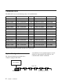
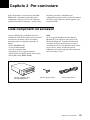
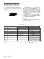
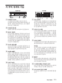
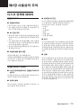
Location and Function of Parts
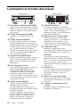
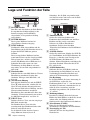
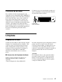
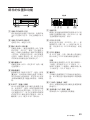
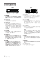
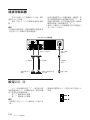
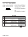
Front Panel
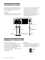
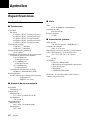
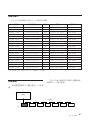
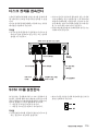
Rear Panel
1
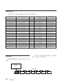
A B C D E F G H
BUSY
AC IN
SCSI ID
0
POWER
SCSI CONNECTOR
F.GND
EJECT
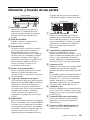
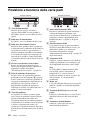
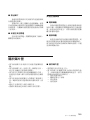
1 POWER switch
Push the button to turn the power on and off.
The power is on when the button is in the
depressed position, and off when fully
protruding.
2 POWER indicator
The green lamp lights up when the power is
turned on.
3 BUSY indicator
As this disk is inserted and the drive becomes
ready for read/write operation, the BUSY
indicator turns green. The orange lamp lights
up when the disk unit is accessing or writing
data. This lamp flashes on and off at about 2second intervals when the unit overheats,
regardless of whether or not a disk is being
accessed.
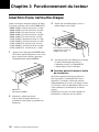
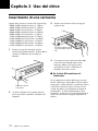
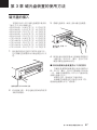
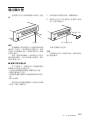
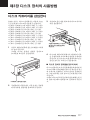
4 Disk insertion slot
Insert the disk cartridge into this slot. Refer
to the section “Inserting a Disk Cartridge” on
page 11 for more information.
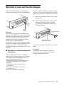
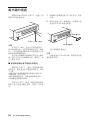
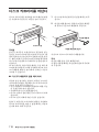
5 Emergency eject hole
If the disk cartridge cannot be ejected using
the EJECT button 6, turn off the power and
insert the supplied emergency eject tool into
this hole to trip the emergency eject
mechanism. Refer to the section “What to do
if the disk does not eject” on page 12 for
further details.
6 EJECT button
Press this button to eject the disk cartridge
from the disk unit. The EJECT button is
disabled with the function switch or software
settings prohibit ejection. When the write
cache is enabled, it may take a few moments
(up to 45 seconds) for the disk to eject
because data in the cache must first be
written to the disk.
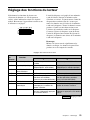
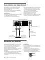
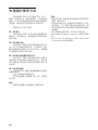
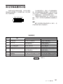
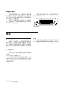
1 Function switches
Use this switches to set the disk unit’s
functions in accordance with the host
computer and software being used. Refer to
the section“Setting the Disk Unit’s
Functions” on page 10 for more information.
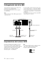
2 SCSI ID switch
Use these switches to set the SCSI ID. Push
the “–” button to lower the ID number; push
the “+” button to raise the ID number. Refer
to the section“Setting the SCSI ID”on page 9
for more information.
3 SCSI connectors
Plug SCSI cables (sold separately) linking
the host computer and other SCSI peripherals
into these connectors.
Note
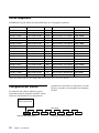
If the disk unit is the last device on the SCSI
chain, set function switch F to “1” to turn on
the internal terminator. When it is not the last
device, make sure that the terminator is off
(switch F is set to “0”).
4 Air duct
The air for cooling the disk unit flows
through this duct, so be careful not to block
its surface or impede the outflow.
5 F.GND (frame ground) terminal
Connect the ground terminals of other
devices to the disk unit’s frame ground.
6 AC IN (AC power) connector
Connect the supplied AC power cord to this
connector.
Chapter 1 Introduction
7