1
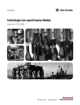
Verdrahtungspläne
Kapitel 8
1756-OB32
ControlLogix-DC-Ausgangsmodul (10–31,2 V)
1756-OB32
Vereinfachtes Schaltbild
DC-0(+)
+5 V
OUT-0
RTN OUT-0
ControlLogix-Backplane-Schnittstelle
Group 0
Daisy Chain
to Other
RTBs
Anzeige
Stoßstromdiagramm
Stoßstrom
1 A
Strom
Group 1
Dauerstrom bei 60 °C
0,5 A
0
10 ms
Zeit
OUT-1
OUT-3
OUT-5
OUT-7
OUT-9
OUT-11
2
1
4
3
6
5
8
7
10
9
OUT-0
OUT-2
OUT-4
OUT-6
OUT-8
OUT-10
12 11
OUT-13
OUT-15
DC-0(+)
14 13
OUT-17
OUT-19
OUT-21
OUT-23
OUT-25
OUT-27
20 19
OUT-29
OUT-31
DC-1(+)
32 31
16 15
18 17
OUT-16
OUT-18
OUT-20
OUT-22
OUT-24
OUT-26
22 21
24 23
26 25
28 27
30 29
Group 1
OUT-28
OUT-30
RTN OUT-1
34 33
36 35
+
Group 0
OUT-12
OUT-14
RTN OUT-0
_
DC COM
Rockwell Automation-Publikation 1756-UM058G-DE-P – November 2012
169