1
AXIS Q1775 Network Camera
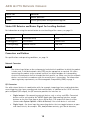
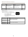
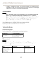
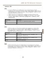
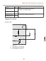
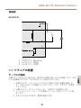
etc. When a signal is received the state changes and the input becomes active (shown
under System Options > Ports & Devices).
ENGLISH
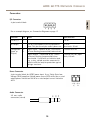
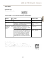
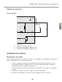
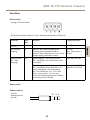
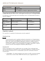
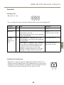
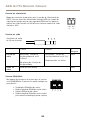
Power Connector
2-pin terminal block for AC/DC power input.
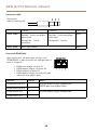
Audio Connector
The Axis product has the following audio connectors:
•
•
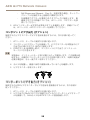
Audio in (pink) – 3.5 mm input for a mono microphone, or a line-in mono signal.
Audio out (green) – 3.5 mm output for audio (line level) that can be connected to
a public address (PA) system or an active speaker with a built-in amplifier. A stereo
connector must be used for audio out.
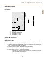
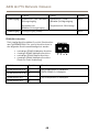
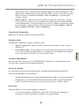
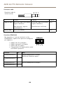
RS485/RS422 Connector
Two terminal blocks for RS485/RS422 serial interface used to control auxiliary equipment such as
pan-tilt devices.
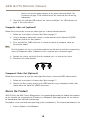
Control Button
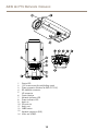
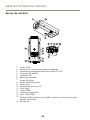
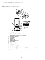
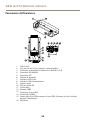
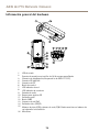
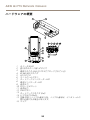
For location of the control button, see Hardware Overview on page 9 .
The control button is used for:
•
•
•
Resetting the product to factory default settings. See page 19.
Ensuring the camera is level. Press the button for not more than two seconds to start the
levelling assistant and press again to stop. The status LED and buzzer signal (see page 12)
assist levelling of the camera. The camera is level when the buzzer beeps continuously.
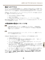
Connecting to an AXIS Video Hosting System service or AXIS Internet Dynamic DNS
Service. For more information about these services, see the User Manual.
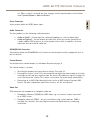
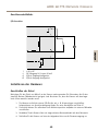
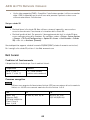
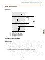
Video Out
RCA connectors for component or composite video out.
•
•
Component video out (Y/Pb/Pr) for HDTV video, e.g. an entrance camera connected
to an HDTV screen.
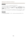
Composite video out (CVBS) - for easy installation using a video monitor. CVBS is
available for 2 minutes after pressing the button and should only be used during
installation.
13