1
AXP1620 Shelf Installation
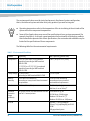
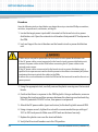
9. Break the tagout or lockout seals on the branch circuit or power distribution unit.
10.Apply power by closing the branch circuit or power distribution unit.
The OOS indicator LED will glow solid red and the other LEDs will go dark. The OOS
will not go dark and the IS indicator LED will not illuminate until the external power
circuit breakers are closed.
11.Verify that all FRU LEDs illuminate and the PEM’s IS LED is green, and the OOS LED
is dark.
5.10
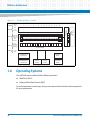
Powering Up the System
With the installation cabled up, you are ready to apply power to the system.
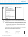
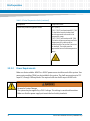
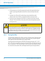
Cover all open module slots and put all approved filler panels in place before turning on
power. This is necessary to properly cool the chassis and to avoid electrical shock and other
possible hazards. Slot covers and panels must remain in place during system operation.
Procedure
Follow these steps to power up the system:
1. Push the PEM circuit breakers to the ON position.
2. Verify that all FRU LEDs illuminate and the PEM’s In Service LED is green.
The system executes its normal start-up routine and is then ready to use.
5.11
Accessing the System
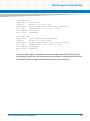
You can access your system using the SAM shelf manager. The SAM-1500 direct serial console
connector (back of chassis) is an RJ45 connector on the SAM face plate. This connector is
configured as DTE. The indirect serial console connector (front of chassis, located on the ADP)
is a 9-pin micro-D subconnector. For default user name and password, contact your Artesyn’s
sales representative.
AXP1620 Installation and Use (6806800E23L)
105