1
OPERATING AND INSTALLATION MANUAL
TRANSMITTER
SE 56
SE56
INDEX
Introduction _______________________________________________________________________________pag.3
Symbols Used on the manual ________________________________________________________________pag.4
Technical characteristics ____________________________________________________________________pag.5
Electrical characteristics ____________________________________________________________________pag.5
Environmental conditions of use______________________________________________________________pag.5
Operative temperature _____________________________________________________________________pag.5
Overall dimensions ________________________________________________________________________pag.6
Electrical connections_______________________________________________________________________pag.7
Grounding instructions _____________________________________________________________________pag.7
Power supply converter ____________________________________________________________________pag.7
Electrical connections: input-output cables _____________________________________________________pag.8
Electrical connections: sensor cables __________________________________________________________pag.9
Inputs/outputs ___________________________________________________________________________ pag.10
Expansion modules _______________________________________________________________________ pag.11
Digital Input ____________________________________________________________________________ pag.12
Converter visualisation pages ______________________________________________________________
Flags interpretation and led ________________________________________________________________
Key board ______________________________________________________________________________
Access codes ____________________________________________________________________________
Programming functions ____________________________________________________________________
How to access to the configuration menu _____________________________________________________
Programming functions ____________________________________________________________________ pag.25
Functions description ___________________________________________________________________ pag.25
Batch ____________________________________________________________________________________
Enable batch ____________________________________________________________________________
Programming batch_______________________________________________________________________
Start / stop batch ________________________________________________________________________
Important notes _________________________________________________________________________
Alarm messages __________________________________________________________________________ pag.33
Causes and actions to be taken _____________________________________________________________ pag.33
Anomalies codes ________________________________________________________________________ pag.33
2
pag.16
pag.37
pag.18
pag.19
pag.20
pag.23
pag.31
pag.31
pag.31
pag.32
pag.32
SE56
INTRODUCTION
This manual is integral part of the product. Read carefully the instructions contained
since they give important indications for the safe use and maintenance.
Technical information and relative products in this manual could undergo modifications
without any previous notice.
The flow meter must be used for what it has been built for. The improper use, possible
modification of the instrument or parts of it and substitutions of any not original
components, automatically invalidate the warranty.
The manufacturer is considered responsible only if the instrument is used in its original
configuration.
START UP AND MAINTENANCE OF THE INSTRUMENTS
Before starting up the instrument please verify the following:
Power supply voltage must correspond to that specified on the name plate.
Electric connections must be carried out as described at pages 7-8.
Ground connections must be carried out.
Verify periodically:
The integrity of the power supply cables, wiring and other electrical parts
connected
The integrity of the instrument housing (this must not have bruises or other
damages that may compromise the hermetical sealing)
The tightening of the sealing elements (cable glands, covers, etc.)
The status of the mechanical fixing of the instrument on the pipe
3
SE56
Symbol Used on the manual
ATTENTION
ELECTRIC SHOCK DANGER
WARNING
PRECAUTIONS
4
SE56
TECHNICAL CHARACTERISTICS
ELECTRIC CHARACTERISTICS
Classification of the instrument: class I, IP 67, category of installation II
Power supply
versions
Power supply
voltage
Pmax
current
max
LLV
20÷30 Vdc
10 W
1A
INPUT/OUTPUT INSULATION
Inputs/outputs are insulated up to 500V
Output 4÷20 mA and output 24 Vdc are electrically connected
ENVIRONMENTAL CONDITIONS OF USE
The instrument can be installed inside or outside buildings
Altitude: from –200 to 6000 m (from -656 to 19685 feet)
Humidity range: 0÷100% (IP 67)
Line voltage range: (see technical characteristics table)
OPERATING TEMPERATURE
TRANSMITTER
Ambient Temp.
Min.
Max
°C
°F °C °F
-20* -4* 40 104
With fittings S051, S054, S055, S056
Fluid temperature
Min.
Max.
°C
°F
°C
°F
-20
-4
100 **
212 **
* For discontinuous use, the installation of a heating resistance around the pipe
is necessary.
** up to 130 °C (266 °F) for max. 1 hour, with an S051 or S056 fitting
5
SE56
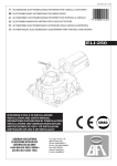
OVERALL DIMENSIONS
107
89
65
177
53
6
SE56
ELECTRICAL CONNECTIONS
GROUNDING INSTRUCTIONS
For the correct operation of the meter it is NECESSARY that sensor and liquid are at the
same potential, so ALWAYS connect sensor and transmitter to the ground.
TRANSMITTER POWER SUPPLY
-
+
before connecting the power supply, verify that the
mains voltage falls between the limits indicated on
the tag plate
ATTENTION: the transmitters are not protected
against polarity reversals.
For the wiring use only approved conductors, with
fire-proof properties.
The power supply line must be equipped with an
external protection for current overload (fuse or
automatic line breaker with limiting capacity not
greater than 10 A).
Provide in the proximity of the instrument a circuit
breaker that must be easily accessible from the
operator and clearly identified.
NOTE: characteristics of meter power supply, see
page 5
7
SE56
ELECTRICAL CONNECTIONS: INPUT / OUTPUT CABLES
+
MAINS POWER
OUTPUT 4÷20
-+
"A" RS485 PROFIBUS
"B" RS485 PROFIBUS
JACK FOR IF21
2
20 21 2
5
23 24 2
26
+ INPUT 2 C. OUTPUT 3
- INPUT 2 E. OUTPUT 3
14 15 16
9
17 18 1
C. OUTPUT 1
E. OUTPUT 1
C. OUTPUT 2
E. OUTPUT 2
+ INPUT 3 C. OUTPUT 4
- INPUT 3 E. OUTPUT 4
+ INPUT 1
- INPUT 1
IN / OUT CABLES
8
SE56
ELECTRICAL CONNECTIONS: SENSOR CABLES
Dangerous voltage:
- 60 Vdc max
- 250 V max commutation coil's circuit
13 12 1
1
1 2 3
4
COIL 1
COIL 2
COMMON
ELECTRODE 2
ELECTRODE 1
CABLES FROM SENSOR
9
SE56
INPUTS / OUTPUTS
Technical characteristics of OUTPUTS
Output 1-2
+ 17 (Out 1)
21 (Out 2)
Max voltage 30 Vdc
Max load:100 mA @24Vdc,
Max. frequency: 1250 Hz.
- 18 (Out 1)
22 (Out 2)
Output 3-4 / Input 2-3
Technical characteristics of OUTPUTS
19 (In 2 or
Out 3)
47K 23 (In 3 or
Out 4)
+
5V1-1/2 W
-
Max voltage 30 Vdc
Max load:100 mA @24Vdc,
Max. frequency: 1250 Hz.
Technical characteristics of INPUTS
20 (In 2 or
Out 3)
24 (In 3 or
Out 4)
Max voltage 30 Vdc
Min voltage applied to recognize the logical
status change: 18 Vdc
Input impedance of the circuit: 47 kohm
Technical characteristics of INPUTS
Input 1
+ 25
47K
Max voltage 30 Vdc
Min voltage applied to recognize the logical
status change: 18 Vdc
Input impedance of the circuit: 47 kohm
5V1-1/2 W
- 26
PROTECTIONS
The terminals are protected against accidental polarity reversals; the output is protected
against overvoltage due to inductive loads (connection of coil or relay).
10
SE56
(Output 0/4..20 mA)
mA
Power supply 20 ÷ 30 VDC
Max resistive load connected to the output:
800 ohm at a 24Vdc power supply
Minimum load recommended 500 Ohm
Response time : 5ms
14
+
I
ATTENTION: The 0-4/20 mA is not
insulated.
0/4..20mA OUT
external supply
COMMUNICATION
MODULE (OPTIONAL)
Terminal block M2
ATTENTION: The communication
module is not insulated.
- + 14 15 16
A
B
RS 485
or
PROFIBUS DP
FOR COMMUNICATION MODULE SEE THE SPECIFIC OPERATION MANUALS
11
SE56
HOW THE INPUT WORKS
Input electric wiring
+ 25
Speed rate
20 Hz
50 Hz
60 Hz
80 Hz
150 Hz
300 Hz
400 Hz
47K
5V1-1/2 W
-
26
Tmin
110 ms
45 ms
40 ms
30 ms
15 ms
10 ms
10 ms
ATTENTION: where not specified, the time T must be
≥ Tmin
The functions refering to the inputs can be divided into three groups:
1.
2.
3.
Functions only assignable to input 1 (page 13)
Functions assignable to inputs 1, 2 and 3 (page 14)
Functions assignable to inputs 1 and 2 or 1 and 3 (see examples at page
15)
remember that the activation of any batch function automatically disables the
operation of any running batch. The list of such functions is suitable in the tab
at page 32.
12
SE56
INPUT OPERATION STAGE (GENERIC FUNCTIONS)
NOTE: “POS. X.Y” refers to the menu position X and sub-menu
position Y (see pages 20 to 30)
Auto-calibration
Tmin<T<1sec. = autocalibration
T > 1 sec. = Autozero
AUTOCALIB. OFF
Necessary conditions to enable the function
18-30 V
0-1,5 V
T
Reset totalizers
•
•
POS. 5.5 ENABLED
•
POS. 6.1-6.2-6.3-6.4 batch functions assigned to
output 1-2-3-4 DISABLED
POS. 5.7-5.8-5.9 batch functions assigned to input 12-3 (optional) DISABLED
Necessary conditions to enable the function
BLOCK
RESET
18-30 V
•
0-1,5 V
POS. 5.1 ÷ 5.2 ENABLED, at least one
Tmin = 100ms
T
Block totalizers
Necessary conditions to enable the function
Block totalizers
18-30 V
0-1,5 V
Totalizers active
Range change
•
POS. 5.4 ENABLED
•
POS. 9.5 (auto-batch) DISABLED
•
POS. 9.7 (cons. mode) DISABLED
Necessary conditions to enable the function
Scale 2
18-30 V
0-1,5 V
Scale 1
•
POS. 5.6 ENABLE
•
POS. 5.6 (batch on input 1) DISABLED
•
POS. 5.8-5.9 batch functions assigned to inputs 23 (optional) DISABLED
N.B.: THE FUNCTIONS POINT OUT ABOVE ARE ENABLED ONLY ON
INPUT 1
13
SE56
OPERATION STAGE ON INPUTS 1 OR 2 OR 3 (BATCH FUNCTION)
Start batch from remote input
Necessary conditions to enable the function
INPUT
18-30 V
0-1,5 V
Closing
valve
BATCH
OUTPUT
Opening
valve
•
POS. 5.7 ENABLED or POS. 5.8 or 5.9 set
to “batch”
•
POS. 6.1 ÷ 6.4 set to “end batch”
Start batch from consent (remote)
Necessary conditions to enable the function
INPUT
18-30 V
0-1,5 V
Closing
valve
Opening
valve
OUTPUT
Opening
valve
BATCH
Start batch from remote input with auto-batch enabled
<5 Sec.
0-1,5 V
Closing valve
quantity to batch
memorized
AUTO-BATCH
Closing
valve
OUTPUT
Opening
valve
BATCH
Start batch from remote input with automatic
selection of formula 00/03
0-1,5 V
INPUT
Start
T
18-30 V
Formula selection
BATCH
INPUT
Start batch from remote input 1
Reset p+ enabled on remote input 1
T
18-30 V
Start
Closing
valve
BATCH
OUTPUT
0-1,5 V
Opening
valve
•
•
POS. 6.1 ÷ 6.4 set to “end batch”
POS. 9.7 (CONSENT MODE) ENABLED
•
POS. 5.7 ENABLED or POS. 5.8 or 5.9 set
to “batch”
•
•
•
POS. 6.1 ÷ 6.4 set to “end batch”
POS. 9.5 (auto-batch) ENABLED
POS. 9.7 (consent mode) DISABLED
T= 100ms ±50ms if formula 00 selected
T= 200ms ±50ms if formula 01 selected
T= 300ms ±50ms if formula 02 selected
T= 400ms ±50ms if formula 03 selected
In case of “stop batch from remote input” the
duration of an input pulse must be > 50ms
Necessary conditions to enable the function
•
Closing
valve
OUTPUT
Opening
valve
POS. 5.7 ENABLED or POS. 5.8 or 5.9 set
to “batch”
Necessary conditions to enable the function
INPUT
18-30 V 5 Sec.
•
•
•
•
•
POS. 5.6 ENABLED or POS. 5.8 or 5.9 set
to “batch”
POS. 6.1 ÷ 6.2 set to “end batch”
POS. 9.6 (BM auto sel) ENABLED
POS. 9.7 (consent mode) DISABLED
POS. 5.8-5-9 functions assigned to BM
SELECT
T BETWEEN 1 AND 4 = RESET TOTALIZER
T<1 = START E RESET TOTALIZER
Necessary conditions to enable the function
•
•
•
POS. 5.6 (batch on imput 1) ENABLED
POS. 6.1 ÷ 6.2 set to “END BATCH”
POS. 5.2 (reset T2) ENABLED
N.B.: THE ACTIVATION OF BATCH FUNCTIONS ON INPUT 2
PREVENTS THE ACTIVATION OF BATCH FUNCTIONS ON INPUT 1
14
SE56
OPERATION STAGE ON INPUTS 1 and 2 or 1 and 3 (BATCH FUNCTION)
Start batch on remote input 1
Stop from output selection formula 00 or 01 from
remote input 2
Necessary conditions to enable the function
Closing
valve
Opening
valve
BATCH FORMULA 00
BATCH FORMULA 01
18-30 V
BATCH FORMULA 00
Closing
valve
Opening
valve
BATCH FORMULA 01
•
•
•
OUTPUT
0-1,5 V
POS. 5.7 ENABLED
POS. 6.1 or 6.3 set to “END BATCH”
POS. 5.8 or/and 5.9 set to “BM SELECT”
INPUT 2
18-30 V
INPUT 1
Start
Block totalizer from remote input 1
Start batch from remote input 2
T
0-1,5 V
INTERRUPTED BATCH
RESTART INTERRUPTED
BATCH
T
18-30 V
Closing
valve
Opening
valve
T
T<1 Sec.
RESET
Start
Start
0-1,5 V
Closing
valve
INTERRUPTED BATCH
NEW BATCH
18-30 V
0-1,5 V
0-1,5 V
Closing
valve
Closing
valve
NEW BATCH
18-30 V
RESET T2
INPUT 1
INTERRUPTED BATCH
BLOCK
Opening
valve
OUTPUT
INPUT 2
Block and reset totalizer from remote input 1
Start batch from remote input 2
Consent mode to batch enabled
Start
18-30 V
Opening
valve
2) T between 1 and 4 Sec =
interrupted batch is reset.
N.B.: it will be necessary to give a
new start pulse at input 2 (T< 1Sec)
to start a new batch
Necessary conditions to enable the
function
•
POS. 5.4 (Count lock) ENABLED
•
POS. 6.1 or 6.3 set to “END BATCH”
•
POS. 5.8 or 5.9 set to “BATCH”
•
POS. 5.2 (T2) ENABLED
INPUT 1
BLOCK
Closing
valve
Opening
valve
OUTPUT
Opening
valve
T between 1 and 4 Sec.
Closing
valve
OUTPUT
Opening
valve
T<1 Sec.
INPUT 2
Start
INPUT 2
Start
18-30 V
Blocking the tolizer causes the current
batch to be interrupted. Exciting again
the input 2 or 3 for a T duration can
have 2 results:
1) if T< 1Sec = interrupted batch is
restarted
0-1,5 V
15
Blocking the totalizer causes the current batch
to be stopped. The function “reset T2 enabled
on descent front” on input 1 resets the
totalizer of the current batch.
Therefore the presence of the consent or a
new pulse on the input 2 or 3 determines the
start of a new batch
Necessary conditions to enable the function
•
•
•
•
POS. 5.4 (Count lock) ENABLED
POS. 5.8 or 5.9 set to “BATCH”
POS. 9.7 (consent mode) ENABLED
POS. 5.2 (T2) ENABLED
VISUALIZATION PAGES (ON THE COMPUTER)
Flow rate value
Analogical bar of flow rate variations
% full scale
Flow direction +/See: error codes and
interpretation of flags
Date/time or alarm
*
Direct / reverse totalizer
C=Calibration
S=Simulation
Sampling rate
Flow speed
Push to change visualisation
Scale (1=low); (2=high)
Flow rate value
Time scale (see Pos. 3.1)
% full scale
% full scale
Measure units
Active scale
Flow direction
* The maximum digit shown from the totalizer is 999999999 independently from the number of
selected decimal. Beyond this value the totalisers are reset.
16
SE56
SE56
Flags interpretation and LED
FLAGS
INTERPRETATION FLAGS
DESCRIPTION
Alarm max activated
Alarm min activated
- Coil circuit interrupted
!
- Signal error
- Empty pipe
C
Calibration running
S
Simulation
Pulse output saturation
(reduce TIME PULSE)
FLAG
M
m
LED
20 21 22
14 15 16
17 18 19
23 24 25
26
LED INTERPRETATION
LIT: initialisation
FLASHING ( 1 sec.): normal function
FLASHING (<1 SEC.): alarm on
The LED signals the real alarm status only if the computer display
visualizes one of the visualization pages suitable to page 17
17
SE56
COMPUTER
KEYBOARD
Increases the digit value or the parameter selected by the cursor
Goes to the previous menu position
Batch start/stop (when enabled)
Decreases the digit value or the parameter selected by the cursor
Goes to the next menu position
Moves the cursor rightward on the input field
Goes to the next menu position
Changes the display of the process data
Moves the cursor leftward on the input field
Goes to the previous menu position
COMPUTER “ENTER” KEY
Enters /leaves the selected function
Enables the main menu for the instrument configuration
Cancels the selected function under progress
COMPUTER “ESC” KEY
Leaves the current menu
Enables the totaliser reset request (when enabled)
Confirms the selected function
BLIND VERSION
The transmitter having no keyboard, the
programming
of functions is made upon a
computer via the IF21 serial device
18
SE56
FACTORY PRE-SETTINGS
ACCESS CODES
ACCESS CODES
Some functions of the transmitter are enabled by the
access codes. The information within this manual is related
to all the functions available with L2 level. All the functions
available through higher level are protected and reserved
to the service.
The transmitter is delivered with a default access code L2:
11111
Description of the L2 access code
With this code, it is possible to access to the "Quick start
menu" by pressing key
from any visualization page
(menu “11 Internal data” pos. 11.1)
setting code L2 to 00000 disables the request of
code
* with L2 customised (freely chosen by the user)
you can proceed programming all the functions up to
L2 security level, entering the code itself whenever
you need to enter the Main menu
*ATTENTION: take note of the customised code you have
chosen, since there is no way for the user to retrieve it if it
is forgotten
19
The “Quick start menu” may be set without entering any
access code (see example 1 on page 21).
The last function of the " Quick start menu" allows the
access to the main menu.
SE56
SE 56 Functions
(functions with symbol “*” are detailed at page 25 and following)
Attention: The functions in grey are visualized on the display only if some other
functions are active or with optional modules
1.1
1.2
1.3
1.4
1.5
Enter Nominal Diameter of sensor ( 0-3000 )
Calibration data of sensor visualized on sensor label
Type of sensor: Enter the first two characters of the serial number of the sensor
Position for insertion sensors: 0=1/8DN, 1=1/2DN, 2=7/8DN
Factory parameter
1.6 Enables the empty pipe detection feature
1.7* Enables the automatic zero calibration system
1.8* Enables the automatic calibration procedure for empty pipe detection
2.1*Full scale value set for range No1
2.2*Full scale value set for range No2
2.3* Measuring unit and number of decimals (totalizers and quantity to batch)
2.4* Pulse value on output 1
2.5* Duration of the pulse generated on output 1
2.6* Pulse value on output 2
2.7* Duration of the pulse generated on output 2
2.8 Specific gravity set in kg/dm³ (enabled only if FS1 or FS2 are set to weight/time)
3.1* Time constant
3.2 Filter on the power supply: 0.1s=“ready” measure; 0.5s=filter of noise on the liquid
3.3* Acceleration threshold
3.4* Anomalous signal peack cut off threshold
3.5 Low flow zero threshold: 0-25% of full scale value
3.6 Enables every hour an internal cycle of calibration. The measure is stopped for 8-15 sec.
3.7* Enables the automatic change of scale
4.1 Maximum value of the direct flow rate alarm
4.2 Maximum value of the reverse flow rate alarm
4.3 Minimum value of the direct flow rate alarm
4.4 Minimum value of the reverse flow rate alarm
4.5 Hysteresis threshold for the minimum and maximum flow rate alarms
4.6 Empty pipe detection threshold. Automatically set by the function 1.6
4.7*Current output value in case of failure
4.8*Batch safety timer
20
SE56
5.1* Total direct (positive) flow totaliser reset enable
5.2* Partial direct (positive) flow totaliser reset enable
Functions assigned
5.3 Reset totaliser of pulse from digital input (see page 13)
On input 1
5.4 Totaliser counting lock command (see page 13)
5.5* Autozero calibration through external control
5.6 Range change through external control (se pos. 3.7)
5.7 Batch start/stop through external control (see batch functions)
5.8* Functions assigned to input 2 (automatically disabled if OUT3 is enabled)
5.9* Functions assigned to input 3 (automatically disabled if OUT4 is enabled)
6.1* Output 1 functions
6.2* Output 2 functions
6.3* Output 3 functions
6.4* Output 4 functions
6.5* Duty cycle value for pulses/frequency output 1
6.6* Duty cycle value for pulses/frequency output 2
6.7* Choice of the function and the range of current output no. 1
7.1
7.2
7.3
7.4
Choice of the communication protocol for the IF2 device
Choice of the communication protocol for the RS232 port
Address value of transmitter (range 0 – 255)
Speed of the RS485 output (possible choices: 2400, 9600, 19200, 38400 bps)
8.1
8.2
8.3
8.4
Choice of the display language: E= English, I=italian, F= French, S= Spanish
Partial totalizer visualization (with batch enable the function is always on)
Updating frequency of the display: 1-2-5-10 Hz
Quick start menu visualization
21
SE56
Menu 9: Menu visualized only IF batch is active
(see page 35 and following)
9.1* Number of batch cycles to be done to define the value of compensation.
9.2* % limit of compensation threshold
9.3* Compensation value
9.4* Prebatch value
9.5* Auto-batch
9.6* Automatic selection of batch formula
9.7* Static consent of batch
10.1*
10.2*
10.3*
10.4
Enable the calibration of the transmitter
Transmitter autotest
Flow rate simulation enabling
Stand-by of transmitter to reduce the consumption during service operation
11.1
11.3
11.4
11.5
11.6
11.7
11.8
Level 2 access code programming
Load default factory data
Load saved user data
Save user data
Visualisation of the total operation hours of the transmitter (can only be read)
Ignore the calibration error during the switch on test
Ks Coefficient
22
SE56
ACCESS TO THE CONFIGURATION MENUS
The access to the configuration menu can take place in two different modes:
Through the “Quick start menu” where it is possible to directly access
some of the principal functions
Through the “Main menu” where it is possible to access to all the functions
with access code ≤ 2
We show below an example relating to the change of value of the “Fs1” function.
See page 18 for using the computer keys.
EXAMPLE: modifying the full scale value from 4dm³/s to 5dm³/s
From the “Quick start menu”
Enter in the “Quick start menu”
Access to function “Fs1”
Push
repeatedly
Change the selected digit value
Confirm the new value
Exit the Quick start menu
Main page
23
SE56
EXAMPLE: modifying the full scale value from 4dm³/s to 5dm³/s
From the “Main Menu” (quick start menu enabled)
Enter in the “Quick start menu”
Access to the “Main Menu”
X 5 TIMES
Access to the “Scale” menu
Change the value
Push
repeatedly
Access to the function “Fs1”
Confirm the new value
Main page
24
SE56
FUNCTION DESCRIPTION
(description of the functions with access code < 3)
Function enabled only with another enabled function or with optional module
Identification of the function (not visualized on display)
MENU 1.SENSOR
* (POS. 1) Nominal diameter of sensor
[ND=
XXXX]
Transmitter request
Menu visualized on the transmitter ( from 1 to 11)
Synthetic description of the function
N.B.: only some functions are detailed hereafter
(see note at page 20)
MENU 1.SENSOR
(POS. 1.7) “Autozero” calibration
[AUTOZERO CAL.]
Enables the automatic zero calibration. To perform the sensor it is absolutely necessary the sensor is
full of liquid and that the liquid is perfectly staying still. Even very small movement of the liquid may
affect the result of this function. When the percentage flow rate value is stable press key
. Check
that the percentage flow rate value goes to zero, otherwise repeat the operation. When the value is
stable at zero, then press key ENTER.
(POS. 1.8) “Empty pipe” calibration
[E.P. CALIBR.]
This function enables the automatic calibration procedure of the empty pipe detection function.
Before performing this function, the sensor has to be completely filled with the liquid. The sensor has
then to be emptied again and then press key ENTER: the operation must be confirmed by pressing
key ESC; any other key press aborts the operation. The parameter can also be changed manually (see
function “E.P.thr” menu 4-ALARMS).
MENU 2.SCALES
(POS. 2.1-2.2) Full scales n° 1-2
[FS1-2=dm³/S X.XXXX]
Full scale values set for range No 1 and 2. There are four fields to fill in order to set this parameter,
from left to right: 1) volume measuring unit, 2) type of unit (see below), 3) time measuring unit and
4) numeric value of the full scale. The selection is made by positioning the cursor on the field to
modify. To change the type of measuring unit (metric, British or American, mass or volume) the
cursor has to be positioned on the symbol “/” (field No 2). When the nominal diameter is set to zero it
is possible to modify only the numeric field, since the measuring unit stays at m/sec. The following
tables show the measuring units available and the conversion factor by comparison with 1 dm3 and 1
kg. The transmitter accepts any kind of combination of measuring units satisfying both the following
conditions:
1. Numeric field value ≤ 99999
2. 1/25 fsmax ≤ numeric field value ≤ fsmax.
Where fsmax is the maximum full scale value corresponding to the sensor, equal to a 10 m/sec liquid
speed. The measuring units are shown as appearing on the display. The British respectively American
units are diversified by using capital resp. small characters.
25
SE56
Available units of mass and volume:
cm3
Cubic centimetre
ml
Millilitre
l
Liter
dm3
Cubic decimeter
dal
Decalitre
hl
Hectolitre
m3
Cubic metre
in3
Gal
GAL
ft3
Bbl
BBL
yd3
kgl
KGL
Cubic inch
American gallon
British gallon
Cubic foot
Standard barrel
Oil barrel
Cubic yard
KAmerican gallon
KBritish gallon
G
Kg
T
Oz
Lb
Ton
Gram
Kilogram
Ton
Ounce
Pound
short tons
When a mass measuring unit is set, the specific gravity function is automatically enabled by the
system. The time measuring unit may be chosen among the values: s=second,m=minute,h=hour,d=
day.
(POS. 2.3) Measuring unit and number number of decimals
[UM.tot:dm³X.XXX]
Setting the measuring unit and number of decimals for visualized the totalizes or the volumes to
batch. To set the measuring unit position the cursor on the actual measuring unit field; To set the
type of unit, position the cursor on the blank space between the measuring unit and the numeric
value that follows; To set the number of decimals for the totalizing amounts
position the cursor on the numeric value of the field and choose one of the possible combinations:
1000-01.00-001.0-00001.
*(POS.2.4-2.6) Pulse value on outputs 1-2 and measuring unit
[IMP1-2=dm³X.XXXXX]
Setting the pulse volume corresponding to outputs 1-2 and measuring units of the totalizers. There
are three fields to fill in to set this parameter, from left to right: 1) measuring unit, 2) unit type and 3)
numeric value. The selection is performed by positioning the cursor on the field to be modified. To
change the unit type (metric, British or American, mass or volume) just position the cursor on the
blank space between the measuring unit and the numeric value. When the nominal diameter is set to
zero it is possible to modify only the numeric field since the measuring unit stays at meter (m) or feet
(ft). The possible measuring units are those described above.
(POS.2.5-2.7) Pulse duration on outputs 1-2
[TPLS1-2=msXXXX.XX]
Setting the duration of the pulse generated on outputs 1-2. Its value is expressed in milliseconds and
has to be between 0.4 and 9999.99.
ATTENTION: since the instrument cannot detect which type of device it is connected to, it is up to
the user to verify the set pulse duration is compatible with the external device processing such pulses.
If, for example, an electro-mechanical pulse counter is connected, then two kind of problems may
occur: if the pulse is too long than the coil may burn or, if it is too short, the counter may not be able
to count and eventually even damage the output itself.
MENU 3.MEASURE
(POS. 3.1) Time constant
[TCONST=s XXXX.X]
This parameter affects the integrating filter making the instrument response quicker or slower,
according to the set value. A higher value corresponds to a more stable but slower measure, a
smaller value the opposite. The most common values are from 1 to 5 seconds. The valid values range
from 0 (integral filter disabled) to 6000.0 seconds. The following diagram shows the response of the
instrument for a flow rate variation from 0 to 100% within the T time constant period
(POS. 3.3) Acceleration threshold
Setting the acceleration threshold. The acceleration threshold stands for the limit beyond which a flow
rate variation determines an immediate response at the output, without being filtered by the time
constant. This system allows the instrument to have an immediate response in case of big variations
of the flow rate, filtering (and delaying) the response to small variations. The result of that is a very
stable measure, ready to follow the process. The value is set as percentage of the full scale value
from 0 to 125%. If such a value is set to zero any flow rate variation bigger than 0.5% of the full
scale value will immediately affect the outputs. The following diagram shows the instrument response
in two cases: a flow rate variation from 0 to 10% completely absorbed by the time constant effect
26
SE56
and a variation form 10% to 100% exceeding the acceleration threshold and then immediately sent
to the output. In fact there is always a minimum time between the measure acquisition and the
outputs update.
(POS. 3.4) Peak cut off threshold
[PEAK THR=% XXX]
Setting the anomalous signal peack cut off threshold. This parameter allows setting the maximum
value of deviation of the actual measure sample by comparison with the average one. If the new
value is higher than the set limit, than such a value is “cut” to the limit value. This function is used to
make the meter less sensitive to big perturbations on the flow rate measure, as it may happen when
there are solids in suspension in the liquid hitting against the electrodes determining a high electrical
noise. The permitted values of this function range from 0 to 125 % and are referred to the full scale
value. If this parameter is set to zero the peak detection function is disabled and any new measure
sample will be accepted and processed as it is by the transmitter.
(POS. 3.7) Automatic scale change enable
[AUTORANGE=ON/OFF]
Enables the automatic change of scale. The meter may have two different working ranges in order to
suit to the variable process conditions. In order to get the best results out of this function it is
important range No.2 is bigger than No.1. When the flow rate increases and reaches the 100% of full
scale 1, then the meter automatically switches to scale 2. When the flow rate decreases again
reaching a value from scale 2 equal to 90% of full scale No.1, then the active scale is 1 again.
Allowed values for this parameter: ON / OFF. N.B.: the autorange does not allow using the manual
change of range (see pos. 5.6)
MENU 4.ALARMS
(POS. 4.7) Current output value in case of failure
[mA VAL.FAULT =% XXX]
Setting the value the 0/4...20 mA current output has to emit for the following failures:
empty pipe; coils interrupted; ADC error
The allowed range is from 0 to 120% of the 0..20 mA scale, 120% corresponds to 24 mA and does
not depend on the selected range (0…20 / 4…20 mA). The NAMUR NE43 recommendation requires an
alarm signalling value for the current output lower than 3.6 mA (<18%) or bigger than 21 mA
(>105%). It would then be preferable to set the value of this function at 10%, so that the current
value in case of the a.m. cases would be 2 mA, allowing the following diagnostics:
1. current < 2 mA minus 5%: line interrupted, power supply failure or faulty transmitter;
2. 2 mA minus 5% ≤ current ≤ 2 mA plus 5%: hardware alarm;
3. 4 mA ≤ current ≤ 20 mA: normal working range;
4. 20 mA < current ≤ 22 mA: out of range, measure above 100% f.s.
N.B.: Setting this parameter to zero means disabling the alarm
(POS. 4.9) Batch safety timer
This function is useful to control one or both of the following conditions:
batch valve open and flow rate is nul
batch valve closed and flow rate different from zero.
When this alarm is activated, the batch operation is aborted and the valve is closed. The timer value
is between 0 and 25.5 seconds and is active only if one or more of the batch functions are enabled.
27
SE56
MENU 5.INPUTS
(POS. 5.1-5.2) Modify/reset totalizer enabled
[T/P+RESET=ON/OFF]
From any visualisation page, proceed as follows:
Push key ESC. Set the L2 CODE if required and then push key ESC from the visualization page; at the
required “RESET TOTALIZ.?” Push key ENTER and then key ESC to confirm or any other key to abort
this operation.
(POS.5.5) “Autozero” calibration enabled by external control
[CALIBRATION=ON/OFF]
When this function is active, applying a voltage on the on/off input terminals makes the meter
perform an autozero calibration cycle. ATTENTION: if the voltage pulse is less than 1 sec., the meter
performs a calibration cycle to compensate possible thermal variations. If the voltage pulse is higher
than 1 sec, the meter performs a zero calibration of measure. This function enables/disables the
automatic zero calibration system. To perform the sensor it is absolutely necessary the sensor is full
of liquid and that the liquid is perfectly staying still. Even very small movement of the liquid may
affect the result of this function, and, consequently, the accuracy of the system.
(POS.5.8-5.9) Functions assigned to inputs 2-3
[ING.2-3=XXXXXX]
To choose the function to associate to input 2. The functions are listed in the following table.
FUNCTIONS FOR INPUTS 2-3
OFF: DISABLED
BATCH: START/STOP BATCH
BM SELECT: STATIC SELECTION OF FORMULA
VALV. OPEN: OPEN VALVE COMMAND
STAND-BY: STAND-BY COMMAND (see function 10.4)
MENU 6.OUTPUTS
(POS. 6.1-6.2-6.3-6.4) Function corresponding to on/off outputs 1-2-3-4 [OUT1=XXXXXX]
To choose the function corresponding to digital Output 1. The functions are listed in the table below:
FUNCTION FOR OUTPUT 1,2,3,4
OFF: DISABLED
PLS+: PULSE FOR POSITIVE FLOW RATE (ONLY OUTPUTS 1-2)
PLS-: PULSE FOR NEGATIVE FLOW RATE (ONLY OUTPUTS 1-2)
PLS: PULSE FOR POSITIVE AND NEGATIVE FLOW RATE (ONLY OUTPUTS 1-2)
SIGN: FLOW DIRECTION OUTPUT (ENERGISED = -)
RANGE: RANGE INDICATION OUTPUT (ENERGISED = SCALE 2)
MAX AL+: MAX DIRECT FLOW RATE OUTPUT (ENERGISED = AL. OFF)
MAX AL-: MAX REVERSE FLOW RATE OUTPUT (ENERGISED = AL. OFF)
MAX AL: MAX DIRECT/REVERSE FLOW RATE OUTPUT (ENERGISED = AL. OFF)
MIN AL+: MIN DIRECT FLOW RATE OUTPUT (ENERGISED = AL. OFF)
MIN AL-: MIN REVERSE FLOW RATE OUTPUT (ENERGISED = AL. OFF)
MIN AL: MIN DIRECT/REVERSE FLOW RATE OUTPUT (ENERGISED = AL. OFF)
MAX+MIN±: MAX AND MIN FLOW RATE ALARM OUTPUT (ENERGISED = AL. OFF)
P.EMPTY: EMPTY PIPE ALARM OUTPUT (ENERGISED = FULL PIPE)
OVERFLOW.: OUT OF RANGE ALARM OUTPUT (ENERGISED = FLOW RATE OK)
HARDW AL.: CUMULATIVE ALARM OUTPUT interrupt coils, empty pipe, measuring error (ENERGISED = NO ALARMS)
EXT. COMM.: ONLY AVAILABLE WITH DATA LOGGER MODULE
BATCH AL: BATCH ALARM
BATCH SYN.: AT THE END OF BATCH THE OUTPUT STATUS CHANGES
END BATCH.: END BATCH OUTPUT (ENERGISED =BATCH IN PROGRESS)
PREBATCH.: PREBATCH OUTPUT (ENERGISED = PREBATCH IN PROGRESS)
(POS. 6.5-6.6) Duty cycle value for pulses/frequency outputs
[OUT.1-2=XXXXXX]
The duty cycle function defines the time ratio between ON and OFF states when frequency outputs
are used: 50% means that the ON phase is equal to the OFF phase, 60% means that phase ON will
last 60 % and phase OFF 40% of the total time cycle. When pulse outputs are used, the duty cycle
defines only the OFF phase because the ON phase is already set with the function "PULSE
DURATION" (see menu “SCALE”). In this case if, for example, the duty cycle is set to 50% and the
pulse duration to 50ms, the OFF phase will be equal to the ON phase. The formula to calculate the
minimum time of the OFF phase and the duration of the total cycle is the following:
T. total cycle= 100 x (pulse duration in ms)/ (duty cycle)
T. OFF phase = T. total cycle - pulse duration
28
SE56
(POS. 6.7) Function and range of current output no.1
[OUT.mA1=X÷XX±]
To choose the function and the range of current output No.1. There are three fields to modify this
function:
Scale zero: 4 or 0 mA ; Full scale: 20 or 22 mA
Field: + = positive, - = negative, ± = both, -0+ = central zero scale
The values corresponding to the scale points are shown in the following chart:
POSSIBLE FIELD
OutmA = 0 ÷ 20 +
OutmA = 0 ÷ 22 +
OutmA = 4 ÷ 20 +
* OutmA = 4 ÷ 22 +
OutmA = 0 ÷ 20 OutmA = 0 ÷ 22 OutmA = 4 ÷ 20 OutmA = 4 ÷ 22 OutmA = 0 ÷ 20 ±
OutmA = 0 ÷ 22 ±
OutmA = 4 ÷ 20 ±
OutmA = 4 ÷ 22 ±
OutmA = 0 ÷ 20 –0+
OutmA = 0 ÷ 22 –0+
** OutmA = 4 ÷ 20 –0+
OutmA = 4 ÷ 22 –0+
CURRENT VALUES IN mA ASSOCIATE TO THE % VALUE OF FULL SCALE
REVERSE FLOW VALUE
ZERO
DIRECT FLOW VALUE
≤ -110%
-100%
0%
+100%
≥+110%
0
0
0
20
20
0
0
0
20
22
4
4
4
20
20
4
4
4
20
22
20
20
0
0
0
22
20
0
0
0
20
20
4
4
4
22
20
4
4
4
20
20
0
20
20
22
20
0
20
22
20
20
4
20
20
22
20
4
20
22
0
0
10
20
20
0
1
11
21
22
4
4
12
20
20
4
4.8
12.8
20.8
22
In hardware alarm conditions “HW ALARM” (interrupted coils, empty pipe, measuring error) the
current value is programmed by the function “mA VALL. FAULT” (pos. 4.7) and it is expressed as
percentage of a fixed current range, where: 0% = 0 mA and 110% = 22 mA.
* Example 1: out 4÷22 +
** Example 2: out 4÷20 –0+
I (mA)
I (mA)
22 mA
20 mA
20 mA
12 mA
4 mA
-110% F.S. -100% F.S.
4 mA
+100% F.S. +110% F.S.
-110% F.S. -100% F.S.
zero
+100% F.S. +110% F.S.
zero
MENU 9 BATCH
Menu visualized only if batch feature active (output on batch and/or pos. 5.9 enabled or
5.10 on batch)
(POS. 9.1) Number of batch samples
[N.SAMPLES=XXX]
Number of batch cycles needed to define the value of compensation. This function allows to
automatically determine the average value for automatic compensation of system delay (POS. 9.3) .
Set this function to ZERO for manually introduction of the compensation value.
(POS. 9.2) % limit of compensation
[DIFF.THR=%XXX]
This value defines the percentage of the maximum difference between the compensation value set
(see pos. 9.3) and the average compensation value defined with the function 9.1. Over this threshold
the new compensation value will be automatically set (if Number of batch samples is different from
zero).
(POS. 9.3) Compensation value
[V.COM.=XX.XXX]
This value, expressed in the same selected volume measuring unit, is the result of the difference
between the batch value set and the quantity of product really supplied due to the system delays:
closing valves, stop pumps, stop motors, etc. Attention: if you need to set manually the value of
compensation, preset to ZERO the number of batch samples (POS. 9.1)
29
SE56
(POS. 9.4) Prebatch value
[V.PRE.=XX.XXX]
To set the volume of liquid at which you want to enable the pre-batch. When the pre-batch volume
“V Pre” is reached the output (if enabled) is de-activated. This value is constant for all quantities to be
batched and must be set in current volume measuring unit. The pre-batch function is useful when
you need fast and accurate fillings.
(POS. 9.5) Enable/disable auto-batch function
[AUTO BATCH=ON/OFF]
Apply a voltage on the on/off input terminals for more than 5 seconds: the valve controlled by the
meter stands open while the voltage is applied on the input. When the product has reached the
desired volume/level, remove the voltage from the input: the meter closes the valve and memorizes
the supplied product volume in the current memory batch (see "BATCH FUNTIONS"); the value
obtained with this procedure will be the volume/level supplied in every following batch. In order to
modify this value, repeat the operations above. This procedure sets the safety timer at a value 1.25
times greater than the time used to reach the batched quantity; after that the counter will be reset.
(POS. 9.6) Automatic selection of batch formula
[BM AUTO SEL=ON/OFF]
The function allows the automatic selection of the first 4 formulas depending on the duration of the
pulse of the batch start (see page 13 "Input operation stage"). This function is active only if the
function cons. mode (POS. 9.7) has not enabled. Besides, activating this function, the automatic
compensation of the batch volume is also excluded (the value of the parameter "N.medie" (POS. 9.1)
will be automatically set to zero). However the manual compensation is possible introducing the
opportune value on the parameter "V.com" (POS. 9.3)
(POS. 9.7) Static consent of batch
[Cons. mode=ON/OFF]
The function enables the start and the stop of the dosing using a static signal, instead of a pulse
signal, applied to the input (see pag. 14 "Digital input), this signal must be applied all through the
batch. This function automatically disables the functions "BM AUTO SEL" (POS. 9.6) and " AUTO
BATCH" (POS. 9.5).
MENU 10. DIAGNOSTIC
(POS. 10.1) Meter “calibration”
[CALIBRATION]
Enables the calibration of the meter. Activate this function by pressing key ENTER: the display shows:
" EXECUTE?"; press ESC for more than two seconds to proceed. Press any other key to abort the
operation
(POS. 10.2) “Autotest” function enable
[SELF TEST]
Meter autotest function. This function stops the normal functions of the meter and performs a
complete test cycle on the measuring input circuits and on the excitation generator. To activate this
function, when selected, push key ENTER; at the question: “EXECUTE?” push key ESC to start
autotest, or any other key to abort the operation. The result of the test is shown on the display. At
the end of operation one visualization page is displayed. This function is automatically performed
when switching the device on.
(POS. 10.3) Flow rate simulation
[SIMULATION]
Flow rate simulation enabling. With this function it is possible to generate an internal signal that
simulates the flow rate, allowing the outputs and all the connected instruments to be tested. After
enabling it, the flow rate simulation can be:
- set: by pushing key
from one of the four visualization pages
- started: by pushing key ENTER after setting it
- finished: by pushing key
from any visualization page and then pushing key ESC.
30
SE56
BATCH FUNCTION
ENABLE BATCH
Enable one of the following functions to enable and program the batch on the transmitter:
POS. 5.7-5.8-5.9: START/STOP batch from input
POS. 6.1-6.2-6.3-6.4: assign one of the functions to one of both outputs
Some examples of operation of such functions are visualized on page 14 and following.
VISUALIZATION PAGE WITH BATCH FUNCTION ENABLE
Programming formula n°
Name of the product to batch
Batch in progress
Visualizations:
1) batch off: n° batch effected
2) batch on: decrease safety timer
3) programming: programming safety timer
indefinite if timer=0 timer disabled
Programming batch quantity
Visualization batched product
From the visualization pages
See page 18 for using the computer keys.
PROGRAMMING BATCH
For each formula you can
associate:
Input key code
Choose the formula number to associate
quantity batch (between 00 and 15)
Input product quantity for each batch
Input name of product to batch (max 8 characters.)
Input maximum time for batch
If timer = 0, safety timer disabled;
max timer set = 6000 sec.
N.B. if the function “batch alarm” is assigned to an
output, the output is activated as soon as the timer
has elapsed, except if the batch is interrupted.
31
Product quantity
Product name
Maximum time for a
batch (safety time for
each formula)
After activating the batch
function
from
any
visualization page at pages
18, proceed as shown in
the opposite example.
SE56
START STOP BATCH
START: it is possible to start a batch in two different ways:
1.
2.
from a remote input: assigning the functions of start/stop batch to input 1 (POS. 5.7)
or inputs 2-3 (POS. 5.8-5.9) and using the input/s like visualized at page 14 and
following.
from the keyboard: short press of key
N.B.: the start of batch from the keyboard is always on the descent front (release of the
key) and is not available with the function of batch consent (POS. 9.7)
STOP: the stop of batch can be due to three events:
1.
2.
3.
keyboard or remote input (manual stop): short pressing of the key
end of batch: in this case the stop of batch will have activated from a output signal to
the attainment of the batch quantity
maximum duration of batch: if a maximum batch duration has been set and this is
exceeded, the batch in progress is stopped independently from the batched quantity
Notes:
during the batch the symbol of the active batch
formula are visualized on the computer display.
and the name of the
When the batch outputs are enabled, pushing for more than 5 sec. key
will cause
the outputs remain energized till the key is released. On the display, in place of the CT
and ST totalises the following messages will appear:
!! VALVE !!
!! OPENED !!
IMPORTANT NOTES
POS
3.7-5.6
POS 5.5
POS 5.7
POS 9.7
CONS. MODE
POS 5.7
INPUT 1 ON BATCH
DISABLE
DISABLE
POS 5.8
INPUT 2 ON BATCH
DISABLE
DISABLE
DISABLE
POS 5.9
INPUT 3 ON BATCH
DISABLE
DISABLE
DISABLE
POS 6.1-6.2-6.3-6.4
OUTPUT 1-2-3-4 ON BATCH
FUNCTIONS
DISABLE
DISABLE
POS 6.3-6.4
OUTPUT 3-4 ON ANY
FUNCTION
POS 5.10
BM SELECT
INPUT 1 (BATCH)
BM AUTO SEL
N. SAMPLES
AUTO BATCH
POS 9.6
COUNT LOCK
POS 9.5
THEN
IF
POS 5.8
POS
5.9
INPUT 3
POS 9.1
INPUT 2
BM AUTO SEL
POS 5.4
CALIBRATION
POS 9.6
AUTO RANGE
CHANGE OR FROM
INPUT
POS 9.5
AUTO BATCH
Relation between functions assigned to the input and automatic settings of IN/OUT :
*DISABLE
** DISABLE
DISABLE
DISABLE
* DISABLE
DISABLE
DISABLE
DISABLE
DISABLE
DISABLE
** DISABLE
* IF INPUT 1 USED
** SET VALUE TO ZERO
To optimize the perfoas the meter used as a batch instrument, it is recommended to program
it as prompt as possible according to the plant requirements, choosing the opportune values
of time constant (pos. 3.1) and acceleration threshold (pos. 3.2).
32
SE56
Alarm messages, causes and actions to be taken
Messages
ANOMALIES
NO ALARMS
ACTION TO TAKE
Everything works regularly
-----
MAX ALARM
The flow rate is higher than the maximum threshold set
Check the maximum flow rate threshold set and the
process conditions
MIN ALARM
The flow rate is lower than the minimum threshold set
Check the minimum flow rate threshold set and the
process conditions
FLOW RATE >FS
The flow rate is higher than the full scale value set on the
instrument
Check the full scale value set on the instrument and
the process conditions
PULSE/FREQ>FS
The pulse generation output of the device is saturated and
cannot generate the sufficient number of pulses
Set a bigger unit of volume or, if the connected
counting device allows it, reduce the pulse duration
value
The measuring pipe is empty or the detection system has not
been properly calibrated
Check whether the pipe is empty or perform again
the empty pipe calibration procedure
EMPTY PIPE
Batch interrupted for the followings condition:
BATCH ALARM
Timer batch expired before the end of the
batch
Batch valve open and flow rate to zero for a
time longer than the safety timer set
batch valve closed and flow rate different from
zero for a time longer than the safety timer
set
Verify:
presetting
system condition
The measure is strongly disturbed by external noise or the cable
connecting the transmitter to the sensor is broken
Check the status of the cables connecting the
sensor, the grounding connections of the devices or
the possible presence of noise sources
EXCITATION FAIL
The coils or the cable connecting the sensor are interrupted
Check the connecting cables to the sensor
CURR. LOOP
OPEN
The 0/4...20mA output on board or the optional one are not
correctly closed on a valid load
INPUT NOISY
P.SUPPLY FAIL
Verify the load is applied to the output (max 1000
ohm).
To disable the alarm, set the “mA VAL.FAULT” value
( menu alarm ) to 0.
Verify that the power supply suits to that specified
on the label
Power supply different from that specified on the label.
Anomalies codes
CODES
0001
0002
0004
0008
0010
0020
0040
0080
0200
ANOMALIE DESCRIPTIONS
problem with watch-dog circuit
wrong configuration work data in eeprom
wrong configuration safety data in eeprom
defective eeprom
defective keyboard (one or more key are pushed during the test)
Power supply voltage (+3.3) is out of range
Power supply voltage (+13) is too low (<10V)
Power supply voltage (+13) it’s too high (>14V)
timeout calibration input (input circuit is broken)
ACTION TO TAKE
SEND DEVICE BACK
0400
Input stage gaining is out of range
Check the status of the cables connecting the sensor to
the transmitter, the grounding connections of the
devices or the possible presence of strong and
anomalous noise sources
0800
Interruption on the coils circuit
Check the status of the cables connecting the sensor to
the transmitter
0C00
Cumulative alarm 0800 + 0400
see both single codes
33
SE56
DECLARATION OF CONFORMITY
According to ISO / IEC Guide 22 and EN 45014
Product name: Electromagnetic flow meter series’
SE 56
Transmitter model: SE56
Option: all applicable
Sensor models: S051 – S054 – S055 – S056
BURKERT declares that the above mentioned products satisfy the
following requirements:
Safety
EN61010, dielectric strength = 4 kV, installation category II, IP65
EMC
EMC reference :
Immunity: EN 61326-1
Emission: EN 61326-1
Test :
EN55011 (150 kHz – 30 MHz): Group 1, class B
EN55011 (30 MHz – 1GHz): Group 1, class B
IEC 1000-4-2: 4 kV CD, 8 kV AD
IEC 1000-4-3 (f = 80 MHz – 1 GHz, antenna at 3 m, AM modulation 1kHz
80%): 10 V/m
IEC 1000-4-4: 4 kV on all ports
IEC 1000-4-5 (2kV diff/2kV common mode)
IEC 1000-4-6 (f = 150 kHz – 80 MHz, AM modulation 1 kHz 80%): 10 V
IEC 1000-4-11
34
MANUEL D’INSTALLATION ET D’UTILISATION
TRANSMETTEUR
SE 56
SE56
INDEX
Introduction _____________________________________________________________________________ page 3
Symboles utilisés dans le manuel ____________________________________________________________ page 4
Caractéristiques techniques ________________________________________________________________
Caractéristiques électriques ________________________________________________________________
Conditions ambiantes d'utilisation____________________________________________________________
Température opérative ____________________________________________________________________
Dimensions générales _____________________________________________________________________
page
page
page
page
page
5
5
5
5
6
Branchements électriques __________________________________________________________________
Instructions de mise à la terre ______________________________________________________________
Convertisseur d'alimentation________________________________________________________________
Branchements électriques : câbles entrée-sortie ________________________________________________
Branchements électriques : câbles du capteur __________________________________________________
page
page
page
page
page
7
7
7
8
9
Entrées/Sorties ___________________________________________________________________________page 10
Modules d’expansion ______________________________________________________________________page 11
Entrée numérique ________________________________________________________________________page 12
Pages de visualisation du convertisseur _____________________________________________________page
Interprétation des indicateurs et DEL _________________________________________________________page
Clavier _________________________________________________________________________________page
Codes d'accès ___________________________________________________________________________page
Programmation des fonctions _______________________________________________________________page
Comment accéder au menu de configuration ? _________________________________________________page
Programmation des fonctions ______________________________________________________________page 25
Description des fonctions __________________________________________________________________page 25
Dosage ___________________________________________________________________________________page
Activer dosage___________________________________________________________________________page
Programmation du dosage _________________________________________________________________page
Démarrer/Arrêter le dosage ________________________________________________________________page
Remarques importantes ___________________________________________________________________page
Messages d'avertissement _________________________________________________________________page 33
Causes et mesures à prendre _______________________________________________________________page 33
Codes d'anomalies _______________________________________________________________________page 33
2
16
37
18
19
20
23
31
31
31
32
32
SE56
INTRODUCTION
Le présent manuel fait partie intégrante du produit. Lisez attentivement les instructions
qu’il contient car elles donnent des indications importantes pour une utilisation et un
entretien en toute sécurité.
Les informations techniques et produits correspondants du manuel peuvent être modifiés
sans avertissement préalable.
Le débitmètre doit être utilisé conformément à l'usage prévu. Une utilisation inadéquate,
une éventuelle modification de l’instrument ou de parties de celui-ci et le remplacement
de composants qui ne sont pas d’origine invalident automatiquement la garantie.
Le fabricant est uniquement jugé responsable si l’instrument est utilisé dans sa
configuration originale.
DÉMARRAGE ET ENTRETIEN DES INSTRUMENTS
Avant de démarrer l’instrument, veuillez vérifier :
La tension d’alimentation doit correspondre à celle indiquée sur la plaque
d’identification.
Les branchements électriques doivent être réalisés comme décrit aux pages 7-8.
Les connexions de masse doivent être réalisées.
Vérifier périodiquement:
L’intégrité des câbles d’alimentation, du câblage et d’autres composants
électriques connectés
L’intégrité du boîtier de l’instrument (absence de traces d’usure ou d’autres
dommages susceptibles de compromettre l’étanchéité)
Le serrage des éléments d’étanchéité (presse-étoupes, couvercles, etc.)
L’état de la fixation mécanique de l’instrument sur le tuyau
3
SE56
Symboles utilisés dans le manuel
ATTENTION
RISQUE
DE
ÉLECTRIQUE
AVERTISSEMENT
PRÉCAUTIONS
4
DÉCHARGE
SE56
CARACTÉRISTIQUES TECHNIQUES
CARACTÉRISTIQUES
ÉLECTRIQUES
Classification de l’instrument : classe I, IP 67, catégorie d’installation II
Versions
d’alimentation
Tension
d’alimentation
Pmax
courant
max.
LLV
20-30 Vdc
10 W
1A
ISOLATION DES ENTRÉES / SORTIES
Les entrées/sorties sont isolées jusqu’à 500V
Les sorties 4-20 mA et 24 Vdc sont raccordées par un circuit électrique
CONDITIONS AMBIANTES D'UTILISATION
L’instrument peut être installé à l’intérieur ou à l’extérieur des bâtiments
Altitude : de –200 à 6000 m (de -656 à 19685 pieds)
Plage d’humidité : 0-100% (IP 67)
Plage de tension du secteur : (voir tableau des caractéristiques techniques)
TEMPERATURE DE
FONCTIONNEMENT
TRANSMETTEUR
Temp. Ambiante
Min.
Max.
°C
°F °C °F
-20* -4* 40 104
Avec raccords S051, S054, S055, S056
Temp. du fluide
Min.
Max.
°C
°F
°C
°F
-20
-4
100 **
212 **
* Pour une utilisation discontinue, l’installation d’une résistance chauffante autour de
la canalisation est nécessaire.
** jusqu’à 130 °C (266 °F) pendant max. 1 heure, avec un raccord S051 ou S056
5
SE56
DIMENSIONS GENERALES
107
89
65
177
53
6
SE56
BRANCHEMENTS ELECTRIQUES
INSTRUCTIONS DE MISE A LA
TERRE
Pour le bon fonctionnement du compteur, il est NÉCESSAIRE que le capteur et le liquide
aient le même potentiel. Connectez donc TOUJOURS le capteur et le transmetteur à la
terre.
ALIMENTATION DU
TRANSMETTEUR
-
+
Avant de brancher l’alimentation, vérifiez que la
tension de secteur se situe dans les limites indiquées
sur la plaque d’identification
ATTENTION : les transmetteurs ne sont pas
protégés contre les inversions de polarité
Pour le câblage, utilisez uniquement des conducteurs
homologués, éprouvés anti-feu
La ligne d’alimentation doit être équipée d’une
protection extérieure pour les surcharges de courant
(fusible ou coupe-circuit automatique avec une
capacité limite ne dépassant pas 10A).
Prévoir à proximité de l’instrument un disjoncteur
aisément accessible pour l’opérateur et clairement
identifié
REMARQUE : caractéristiques
transmetteur, voir page 5
7
de
l’alimentation
du
SE56
BRANCHEMENTS ELECTRIQUES :
CÂBLES D’ENTRÉE / SORTIE
+
MAINS POWER
OUTPUT 4÷20
-+
"A" RS485 PROFIBUS
"B" RS485 PROFIBUS
JACK FOR IF21
2
20 21 2
5
23 24 2
26
+ INPUT 2 C. OUTPUT 3
- INPUT 2 E. OUTPUT 3
14 15 16
9
17 18 1
C. OUTPUT 1
E. OUTPUT 1
C. OUTPUT 2
E. OUTPUT 2
+ INPUT 3 C. OUTPUT 4
- INPUT 3 E. OUTPUT 4
+ INPUT 1
- INPUT 1
IN / OUT CABLES
8
SE56
BRANCHEMENTS ELECTRIQUES :
CABLES DU CAPTEUR
Tension dangereuse :
- 60 Vdc max
- 250 V max. pour le circuit de la bobine de
commutation
13 12 1
1
1 2 3
4
COIL 1
COIL 2
COMMON
ELECTRODE 2
ELECTRODE 1
CABLES FROM SENSOR
9
SE56
ENTREES/SORTIES
Caractéristiques techniques des
SORTIES
Sortie 1-2
+ 17 (Out 1)
21 (Out 2)
Tension max. 30 Vdc
Charge max.:100 mA à 24Vdc,
Fréquence max. : 1250 Hz.
- 18 (Out 1)
22 (Out 2)
Caractéristiques techniques des
SORTIES
Sortie 3-4 / Entrée 2-3
+
19 (ent. 2
ou sortie 3)
47K
23 (ent. 3
ou sortie 4)
Tension max. 30 Vdc
Charge max.: 100 mA à 24Vdc,
Fréquence max. : 1250 Hz.
Caractéristiques techniques des
ENTRÉES
5V1-1/2 W
-
Tension max. 30 Vdc
Tension min. appliquée pour reconnaître le
changement d’état logique: 18 Vdc
Impédance d’entrée du circuit: 47 kohm
20 (ent. 2
ou sortie 3)
24 (ent. 3
ou sortie 4)
Caractéristiques techniques des
ENTRÉES
Entrée 1
+ 25
47K
Tension max. 30 Vdc
Tension minimale appliquée pour reconnaître
le changement d’état logique: 18 Vdc
Impédance d’entrée du circuit: 47 kohm
5V1-1/2 W
- 26
PROTECTIONS
Les broches sont protégées contre les inversions de polarité accidentelles ; la sortie est
protégée contre la surtension due à des charges inductives (connexion de la bobine ou du
relais).
10
SE56
(Sortie 0/4..20 mA)
mA
Alimentation 20 - 30 VDC
Charge résistive max. reliée à la sortie:
800 ohm à une alimentation de 24Vdc
Charge minimale recommandée 500 Ohm
Temps de réponse : 5ms
14
+
I
ATTENTION: le 0-4/20 mA n’est
pas isolé.
0/4..20mA OUT
external supply
MODULE DE
COMMUNICATION (EN OPTION)
Bloc de jonction M2
ATTENTION: le module de
communication n’est pas isolé.
- +14 15 16
A B
RS 485
ou
PROFIBUS DP
POUR LE MODULE DE COMMUNICATION, SE REPORTER AUX MODES D’EMPLOI
SPÉCIFIQUES
11
SE56
MODE DE FONCTIONNEMENT
DE L’ENTRÉE
Câblage électrique de l’entrée
+ 25
Speed rate
20 Hz
50 Hz
60 Hz
80 Hz
150 Hz
300 Hz
400 Hz
47K
5V1-1/2 W
-
26
Tmin
110 ms
45 ms
40 ms
30 ms
15 ms
10 ms
10 ms
ATTENTION: s’il n’est pas spécifié, le temps T doit
être ≥ Tmin
Les fonctions renvoyant aux entrées peuvent être divisées en trois groupes :
1.
2.
3.
Fonctions uniquement affectables à l’entrée 1 (page 13)
Fonctions affectables aux entrées 1, 2 et 3 (page 14)
Fonctions affectables aux entrées 1 et 2 ou 1 et 3 (cf. exemples à la page
15)
N’oubliez pas que l’activation de toute fonction de dosage désactive
automatiquement tout dosage en cours. La liste de telles fonctions est proposée
à la page 32.
12
SE56
ÉTAGE D’ENTRÉE (FONCTIONS GÉNÉRIQUES)
REMARQUE :
« POS. X.Y » fait référence au menu X et au sous-menu Y
(voir pages 20 à 30)
Calibration
automatique
Tmin<T<1sec. = calibration automatique
T > 1 sec. = auto-zéro
AUTOCALIB. OFF
Conditions nécessaires pour activer la fonction
18-30 V
0-1,5 V
T
Réinitialiser
totalisateurs
•
•
POS. 5.5 ACTIVÉE
•
POS. 6.1-6.2-6.3-6.4 fonctions de dosage affectées à
la sortie 1-2-3-4 DÉSACTIVÉES
POS. 5.7-5.8-5.9 fonctions de dosage affectées à
l’entrée 1-2-3 (en option) DÉSACTIVÉES
Conditions nécessaires pour activer la fonction
BLOCK
RESET
18-30 V
•
0-1,5 V
POS. 5.1 - 5.2 ACTIVÉES, l’une au moins
Tmin = 100ms
T
Bloquer
totalisateurs Bloquer totalisateurs
Conditions nécessaires pour activer la fonction
18-30 V
0-1,5 V
Totalisateurs actifs
Changement
de plage
•
POS. 5.4 ACTIVÉE
•
POS. 9.5 (dosage automatique) DÉSACTIVÉE
•
POS. 9.7 (mode cons.) DÉSACTIVÉE
Conditions nécessaires pour activer la fonction
Échelle 2
18-30 V
0-1,5 V
Échelle 1
•
POS. 5.6 ACTIVÉE
•
POS. 5.6 (dosage sur entrée 1) DÉSACTIVÉE
•
POS. 5.8-5.9 fonctions de dosage affectées aux
entrées 2-3 (en option) DÉSACTIVÉES
N.B.: LES FONCTIONS DÉCRITES CI-DESSUS SONT ACTIVÉES
UNIQUEMENT SUR L’ENTRÉE 1
13
SE56
ÉTAPE DE L'OPÉRATION SUR LES ENTRÉES 1, 2 OU 3
(FONCTION DOSAGE)
ENTRÉE
Démarrer dosage à partir de l’entrée
distante
18-30 V
0-1,5 V
DOSAGE
Fermeture
vanne
SORTIE
Ouverture
vanne
Conditions nécessaires pour activer la fonction
•
POS. 5.7 ACTIVÉE ou POS. 5.8 ou 5.9
réglée sur « dosage »
•
POS. 6.1 à 6.4 réglées sur « fin dosage »
ENTRÉE
Démarrer dosage à partir du consentement (distant)
18-30 V
0-1,5 V
DOSAGE
18-30 V
Démarrer dosage à partir de l’entrée distante avec
dosage automatique activé
5 sec.
<5 Sec.
0-1,5 V
Fermeture vanne
Quantité à doser
mémorisée
Ouverture
vanne
DOSAGE AUTOMATIQUE
ENTRÉE
SORTIE
Ouverture
vanne
DOSAGE
Choix des formules
Ouverture
vanne
DOSAGE
Fermeture
vanne
SORTIE
0-1,5 V
ENTRÉE
Début
T
ENTRÉE
Démarrer dosage à partir de l’entrée distante 1
Réinitialiser p+ active sur entrée distante 1
T
18-30 V
Début
Fermeture
vanne
DOSAGE
SORTIE
0-1,5 V
Ouverture
vanne
POS. 5.7 ACTIVÉE ou POS. 5.8 ou 5.9
réglée sur « dosage »
•
•
POS. 6.1 à 6.4 réglées sur « fin dosage »
POS. 9.7 (MODE CONSENTEMENT)
ACTIVÉE
Conditions nécessaires pour activer la fonction
Fermeture
vanne
Démarrer dosage à partir de l’entrée distante avec
sélection automatique des formules 00/03
18-30 V
•
SORTIE
Fermeture
vanne
Ouverture
vanne
Conditions nécessaires pour activer la fonction
•
POS. 5.7 ACTIVÉE ou POS. 5.8 ou 5.9
réglée sur « dosage »
•
•
•
POS. 6.1 à 6.4 réglées sur « fin dosage »
POS. 9.5 (dosage automatique) ACTIVÉE
POS. 9.7 (mode consentement)
DÉSACTIVÉE
T= 100ms ±50ms si formule 00 sélectionnée
T= 200ms ±50ms si formule 01 sélectionnée
T= 300ms ±50ms si formule 02 sélectionnée
T= 400ms ±50ms si formule 03 sélectionnée
Si «arrêt de dosage à partir de l’entrée distante»,
la durée d’une impulsion d’entrée doit être
> 50ms
Conditions nécessaires pour activer la fonction
•
POS. 5.6 ACTIVÉE ou POS. 5.8 ou 5.9 réglée
sur « dosage »
•
•
•
•
POS. 6.1 - 6.2 réglées sur « fin dosage »
POS. 9.6 (auto sél. BM) ACTIVÉE
POS. 9.7 (mode consentement) DÉSACTIVÉE
POS. 5.8 -5.9 fonctions affectées à BM SELECT
T ENTRE 1 ET 4 = RÉINITIALISER
TOTALISATEUR
T<1 = DÉMARRER ET RÉINITIALISER
TOTALISATEUR
Conditions nécessaires pour activer la fonction
•
•
•
POS. 5.6 (dosage sur entrée 1) ACTIVÉE
POS. 6.1 - 6.2 réglées sur « fin dosage »
POS. 5.2 (réinitialiser T2) ACTIVÉE
N.B.: L’ACTIVATION DES FONCTIONS DE DOSAGE SUR L’ENTRÉE 2
EMPÊCHE L’ACTIVATION DES FONCTIONS DE DOSAGE SUR L’ENTRÉE 1
14
SE56
Démarrer dosage sur l’entrée distante 1
Arrêt à partir de la sortie sélection des formules 00 ou
01 à partir de l’entrée distante 2
18-30 V
Début
0-1,5 V
FORMULE DOSAGE 00
SORTIE
FORMULE DOSAGE 01
18-30 V
•
•
•
FORMULE DOSAGE 01
POS. 5.7 ACTIVÉE
POS. 6.1 ou 6.3 réglée sur « fin dosage »
POS. 5.8 ou/et 5.9 réglées sur «BM SELECT»
ENTRÉE 2
FORMULE DOSAGE 00
Conditions pour l’activation de la fonction
Fermeture
vanne
Fermeture Ouverture
vanne
vanne
Ouverture
vanne
ENTRÉE 1
ÉTAPE DE L'OPÉRATION SUR LES ENTRÉES 1 et 2 ou 3
(FONCTION DOSAGE)
Bloquer totalisateur à partir de l’entrée distante 1
Démarrer dosage à partir de l’entrée distante 2
En bloquant le totalisateur, le dosage
actuel est interrompu. Restimuler
l’entrée 2 ou 3 pendant une durée T
peut avoir 2 résultats:
1) si T< 1sec = redémarrage du
dosage interrompu
T
Début
0-1,5 V
Fermeture
vanne
Fermeture Ouverture
vanne
vanne
18-30 V
REDÉMARRER DOSAGE
INTERROMPU
T
T<1 Sec.
T
RÉINITIALISER
Début
Début
0-1,5 V
DOSAGE INTERROMPU
NOUVEAU DOSAGE
18-30 V
ENTRÉE 1
BLOQUER
Fermeture
vanne
Ouverture
vanne
SORTIE
Fermeture
vanne
Ouverture
vanne
T entre 1 et 4 sec.
DOSAGE INTERROMPU
SORTIE
Ouverture
vanne
T<1 Sec.
ENTRÉE 2
Début
ENTRÉE 2
18-30 V
0-1,5 V
2) T entre 1 et 4 sec = réinitialisation
du dosage interrompu.
N.B.: il sera nécessaire de donner une
nouvelle impulsion de départ à
l’entrée 2 (T< 1 sec) pour démarrer
un nouveau dosage
Conditions nécessaires pour activer la
fonction
•
POS. 5.4 (Count lock) ACTIVÉE
•
POS. 6.1 ou 6.3 réglée sur « fin
dosage »
•
POS. 5.8 ou 5.9 réglée sur “DOSAGE”
•
POS. 5.2 (T2) ACTIVÉE
BLOQUER
18-30 V
RÉINITIALISER
0-1,5 V
15
ENTRÉE 1
NOUVEAU DOSAGE
DOSAGE INTERROMPU
SORTIE
ENTRÉE 2
Bloquer et réinitialiser totalisateur à partir de l’entrée distante 1
Démarrer dosage à partir de l’entrée distante 2
En bloquant le totalisateur, le dosage actuel
Mode consentement pour dosage activé
est arrêté. La fonction « réinitialiser T2 activé
Début
sur la descente » sur l’entrée 1 réinitialise le
18-30 V
totalisateur du dosage courant.
0-1,5 V
Par conséquent, la présence du consentement
Ouverture
ou une nouvelle impulsion à l’entrée 2 ou 3
vanne
Ouverture
Fermeture
Fermeture
marque le début d’un nouveau dosage
vanne
vanne
vanne
Conditions nécessaires pour activer la fonction
•
•
•
•
POS. 5.4 (Verrouillage comptage) ACTIVÉE
POS. 5.8 ou 5.9 réglée sur “DOSAGE”
POS. 9.7 (mode consentement) ACTIVÉE
POS. 5.2 (T2) ACTIVÉE
PAGES DE VISUALISATION (SUR L’ORDINATEUR)
Valeur de débit
Barre analog. des variations de débit
% pleine échelle
Date/heure ou alarme
Direction du flux +/Voir: codes d’erreur et
interprétation des indicateurs
*
Totalisateur inversé/direct
C=Calibration
S=Simulation
Taux d’échantillonnage
Vitesse d’écoulement
Appuyez pour changer la visualisation
Échelle (1=faible); (2=élevé)
Valeur de débit
Échelle de temps (voir Pos. 3.1)
% pleine échelle
% pleine échelle
Unités de mesure
Échelle active
Direction du flux
* Le chiffre maximal affiché par le totalisateur est 999999999 indépendamment du nombre de
décimales sélectionnées. Au-delà de cette valeur, les totalisateurs sont reinitialisés.
16
SE56
SE56
Interprétation des indicateurs et DEL
INDICATEURS
INTERPRÉTATION DES INDICATEURS
INDICATEUR
DESCRIPTION
M
Alarme max. activée
m
Alarme min. activée
- Circuit bobine interrompu
!
- Erreur de signal
- Tuyau vide
C
Calibration en cours
S
Simulation
Saturation de la sortie impulsion
(réduire DUREE D’IMPULSION)
DEL
20 21 22
14 15 16
17 18 19
23 24 25
26
INTERPRÉTATION DES DEL
ALLUMEE : initialisation
CLIGNOTEMENT (1 sec.): fonctionnement normal
CLIGNOTEMENT (<1 SEC.): alarme activée
Les DEL signalent l’état réel de l’alarme uniquement si l’écran d’ordinateur
affiche l’une des pages de visualisation correspondant à celles de la page
17
17
SE56
CLAVIER
D’ORDINATEUR
Augmente la valeur numérique ou le paramètre sélectionné par le curseur
Accède à la position de menu précédente
Démarrage/arrêt du dosage (si activé)
Diminue la valeur numérique ou le paramètre sélectionné par le curseur
Accède à la position de menu suivante
Déplace le curseur vers la droite sur le champ d’entrée
Accède à la position de menu suivante
Change l’affichage des données du processus
Déplace le curseur vers la gauche sur le champ d’entrée
Accède à la position de menu précédente
TOUCHE «ENTRÉE» DU CLAVIER D’ORDINATEUR
Accède à/quitte la fonction sélectionnée
Active le menu principal pour la configuration de l’instrument
Annule la fonction sélectionnée en cours
TOUCHE «ESC» DU CLAVIER D’ORDINATEUR
Quitte le menu actuel
Active la demande de réinitialisation du totalisateur (si activé)
Confirme la fonction sélectionnée
VERSION AVEUGLE
Le transmetteur n’ayant pas de clavier, la
programmation des fonctions est effectuée sur un
ordinateur à travers le périphérique en série IF21.
18
SE56
PRÉRÉGLAGES USINE
CODES D’ACCÈS
CODES D’ACCÈS
Certaines fonctions du transmetteur sont activées à l’aide
des codes d’accès. Les informations du présent manuel ont
trait à toutes les fonctions proposées au niveau L2. Toutes
les fonctions accessibles à un niveau supérieur sont
protégées et réservées à la maintenance.
Le transmetteur est fourni avec un code d’accès par défaut
L2:
11111
Description du code d’accès L2
(menu “11 Données internes” pos. 11.1)
Le réglage du code L2 sur 00000 désactive la
Avec ce code, il est possible d’accéder au menu
« Démarrage rapide » en appuyant sur la touche
partir de n’importe quelle page de visualisation.
demande de code
* si L2 est personnalisé (libre choix de l’utilisateur),
vous pouvez programmer toutes les fonctions jusqu’au
niveau de sécurité L2, en saisissant le code dès que
vous avez besoin d’accéder au menu principal
*ATTENTION: notez le code personnalisé que vous avez
choisi, car l’utilisateur n’a aucun moyen de le récupérer s’il
est oublié.
19
Le menu « Démarrage rapide » peut être configuré sans
devoir saisir le moindre code d’accès (cf. exemple 1 à la
page 21).
La dernière fonction du menu « Démarrage rapide »
permet d’accéder au menu principal.
à
SE56
Fonctions SE 56
(les fonctions accompagnées du symbole "*" sont détaillées aux pages 25 et
suivantes)
Attention: les fonctions grisées apparaissent uniquement à l'écran si d'autres fonctions sont
1.1
1.2
1.3
1.4
1.5
Saisir le diamètre nominal du capteur ( 0-3000 )
Données de calibration du capteur indiquées sur l'étiquette du capteur
Type de capteur: saisir les deux premiers caractères du no de série du capteur
Position pour insertion des capteurs: 0=1/8DN, 1=1/2DN, 2=7/8DN
Paramétrage usine
1.6 Active la fonction de détection de conduite vide
1.7* Active le système de calibration automatique du zéro
1.8* Active la procédure de calibration automatique pour la détection de conduite
vide
2.1*Valeur pleine échelle définie pour la plage n°1
2.2*Valeur pleine échelle définie pour la plage n°2
2.3* Unité de mesure et nombre de décimales (totalisateurs et quantité à doser)
2.4* Valeur d'impulsion à la sortie 1
2.5* Durée de l'impulsion générée à la sortie 1
2.6* Valeur d'impulsion à la sortie 2
2.7* Durée de l'impulsion générée à la sortie 2
2.8 Gravité spécifique définie en kg/dm³ (activée uniquement si FS1 ou FS2 est
configuré sur poids/temps)
3.1* Constante de temps
3.2 Filtre sur l'alimentation: 0,1s= mesure "prête"; 0,5s=filtre bruit sur le liquide
3.3* Seuil d'accélération
3.4* Seuil de coupure à pleine charge en cas de signal anormal
3.5 Seuil zéro faible flux: 0-25% de la valeur pleine échelle
3.6 Active un cycle interne de calibration toutes les heures. La mesure est arrêtée
pendant 8-15 sec.
3.7* Active le changement automatique d'échelle
4.1 Valeur maximale de l'alarme de débit direct
4.2 Valeur maximale de l'alarme de débit inverse
4.3 Valeur minimale de l'alarme de débit direct
4.4 Valeur minimale de l'alarme de débit inverse
4.5 Seuil d'hystérèse pour les alarmes de débit minimal et maximal
4.6 Seuil de détection de conduite vide. Configuré autom. par la fonction 1.6
4.7*Valeur de sortie du courant en cas de panne
4.8*Minuterie de sécurité du dosage
20
SE56
5.1* Activer réinit. totalisateur de l'écoulement direct total (positif)
5.2* Activer réinit. totalisateur de l'écoulement direct partiel (positif)
Fonctions
5.3 Réinit. totalisateur d'impulsion à partir de l'entrée num. (cf. p. 13)
assignées
5.4 Commande verr. comptage totalisateur (cf. page 13)
à la
5.5* Calibration auto-zéro par contrôle externe
sortie 1
5.6 Changement plage par contrôle externe (cf. pos. 3.7)
5.7 Dém./Arrêt dosage par contrôle externe (cf. fonctions de dosage)
5.8* Fonctions assignées à l'entrée 2 (désactivé automatiquement si OUT3 est
activé)
5.9* Fonctions assignées à l'entrée 3 (désactivé automatiquement si OUT4 est
activé)
6.1* Fonctions sortie 1
6.2* Fonctions sortie 2
6.3* Fonctions sortie 3
6.4* Fonctions sortie 4
6.5* Valeur cycle de fonctionnement pour impulsions/fréquence sortie 1
6.6* Valeur cycle de fonctionnement pour impulsions/fréquence sortie 2
6.7* Choix de la fonction et de la plage de sortie courant n°1
7.1
7.2
7.3
7.4
Choix du protocole de communication pour le dispositif IF2
Choix du protocole de communication pour le port RS232
Valeur d'adresse du transmetteur (plage 0 – 255)
Vitesse de sortie RS485 (possibilités: 2400, 9600, 19200, 38400 bps)
8.1
8.2
Choix de la langue d'affichage: E=anglais, I=italien, F=français, S=espagnol
Visualisation partielle du totalisateur (si dosage activé, fonction toujours active)
8.3
8.4
Mise à jour fréquence d'affichage: 1-2-5-10 Hz
Visualisation du menu Démarrage rapide
21
SE56
Menu 9: Menu uniquement visualisé SI le dosage est actif
(cf. page 35 et suivantes)
9.1* Nombre de cycles de dosage à effectuer pour définir la valeur de compensation
9.2* % limite du seuil de compensation
9.3* Valeur de compensation
9.4* Valeur du prédosage
9.5* Dosage automatique
9.6* Choix automatique des formules de dosage
9.7* Consentement statique du dosage
10.1* Activer la calibration du transmetteur
10.2* Autotest du transmetteur
10.3* Activation de la simulation du débit
10.4 Transmetteur mis en veille pour réduire la consommation en cours de
maintenance
11.1 Programmation du code d'accès de niveau 2
11.3 Charger les données d'usine par défaut
11.4 Charger les données utilisateur enregistrées
11.5 Enregistrer les données utilisateur
11.6 Lecture du nombre total d'heures de fonctionnement du transmetteur
11.7 Ignorer l'erreur de calibration au cours du test d'activation
11.8 Coefficient Ks
22
SE56
ACCÈS AUX MENUS DE CONFIGURATION
L'accès au menu de configuration peut se faire de deux manières:
Par le menu « Démarrage rapide » permettant d’accéder directement à
certaines fonctions principales
Par le « menu principal » permettant d’accéder à l’ensemble des fonctions avec
le code d’accès ≤ 2
Nous présentons ci-dessous un exemple de changement de valeur de la fonction « Fs1 ».
Voir page 18 pour l’utilisation des touches de l’ordinateur.
EXEMPLE: modifier la valeur pleine échelle de 4dm³/s à 5dm³/s
à partir du menu « Démarrage rapide »
Accès au menu « Démarrage rapide »
Accès à la fonction « Fs1 »
Appuyer plusieurs fois
Modifier la valeur numérique sélectionnée
Confirmer la nouvelle valeur
Quitter le menu Démarrage
rapide
Page principale
23
SE56
EXEMPLE: modification de la valeur pleine échelle de 4dm³/s à 5dm³/s
à partir du menu principal (menu démarrage rapide activé)
Accéder au menu « Démarrage
rapide »
Accéder au menu principal
X 5 FOIS
Accéder au menu “Échelle”
Modifier la valeur
Accéder à la function “Fs1”
Appuyer plusieurs fois
Confirmer la nouvelle
valeur
Page principale
24
SE56
DESCRIPTION DES FONCTIONS
(Description des fonctions avec code d’accès < 3)
Fonction activée uniquement avec une autre fonction activée ou un module optionnel
Identification de la fonction (pas visualisé à l’écran)
MENU 1. CAPTEUR
* (POS. 1) Diamètre nominal du capteur
[ND=
XXXX]
Demande du transmetteur
Menu visualisé sur le transmetteur (de 1 à 11)
Description succincte de la fonction
N.B. : seules quelques fonctions sont détaillées ci-après
(cf. note à la page 20)
MENU 1. CAPTEUR
(POS. 1.7) Calibration « auto-zéro »
[AUTOZERO CAL.]
Permet la calibration automatique du zéro. Pour que le capteur fonctionne, il est indispensable qu’il
soit rempli de liquide et que ce dernier reste parfaitement immobile. Même un mouvement
extrêmement faible du liquide est susceptible d'affecter le résultat de cette fonction. Lorsque la valeur
de débit en pourcentage est stable, appuyez sur la touche
. Assurez-vous que la valeur de débit
en pourcentage atteigne zéro, sinon répétez l’opération. Lorsque la valeur est stable sur zéro,
appuyez sur la touche ENTRÉE.
(POS. 1.8) Calibration «conduite vide»
[E.P. CALIBR.]
Cette fonction permet la procédure de calibration automatique de la fonction de détection de conduite
vide. Avant d’exécuter cette fonction, le capteur doit être complètement rempli avec le liquide. Le
capteur doit ensuite être une nouvelle fois vidé, puis appuyez sur la touche ENTRÉE : l’opération doit
ensuite être confirmée en appuyant sur ESC ; une pression sur une autre touche annule l’opération.
Le paramètre peut également être modifié manuellement (cf. fonction « E.P.thr » menu 4-ALARMES).
MENU 2. ÉCHELLES
(POS. 2.1-2.2) Pleines échelles n° 1-2
[FS1-2=dm³/S X.XXXX]
Valeurs pleines échelles définies pour les échelles n°1 et 2. Quatre champs doivent être remplis pour
définir ce paramètre, de gauche à droite : 1) unité de mesure du volume, 2) type d’unité (cf. cidessous), 3) unité de mesure du temps et 4) valeur numérique de la pleine échelle. La sélection est
opérée en positionnant le curseur sur le champ à modifier. Pour modifier le type d’unité de mesure
(métrique, britannique ou américain, masse ou volume), le curseur doit être positionné sur le symbole
« / » (champ n°2). Lorsque le diamètre nominal est défini sur zéro, il est possible de modifier
uniquement le champ numérique puisque l’unité de mesure reste sur m/sec. Les tableaux suivants
indiquent les unités de mesure disponibles ainsi que le facteur de conversion par comparaison avec 1
dm3 et 1 kg. Le transmetteur accepte tout type de combinaison d’unités de mesure satisfaisant les
deux conditions suivantes :
1. Valeur du champ numérique ≤ 99999
2. 1/25 fsmax ≤ valeur du champ numérique ≤ fsmax.
fsmax est la valeur pleine échelle maximale correspondant au capteur, égale à une vitesse de liquide de
10 m/sec. Les unités de mesure sont indiquées telles qu’elles apparaissent à l’écran. Les unités
américaines et britanniques sont respectivement différenciées en utilisant des minuscules et des
majuscules.
25
SE56
Unités de masse et de volume disponibles :
cm3
Centimètre cube
in3
ml
Millilitre
Gal
l
Litre
GAL
dm3
Décimètre cube
ft3
dal
Décalitre
Bbl
hl
Hectolitre
BBL
m3
Mètre cube
yd3
kgl
KGL
Pouce cube
Gallon américain
Gallon britannique
Pied cube
Baril standard
Baril de pétrole
Yard cube
kGallon américain
kGallon britannique
G
Kg
T
Oz
Lb
Ton
Gramme
Kilogramme
Tonne
Once
Livre
Tonne
américaine
Lorsqu’une unité de mesure de masse est définie, la fonction de gravité spécifique est
automatiquement activée par le système. L'unité de mesure du temps peut être choisie parmi les
valeurs suivantes : s=seconde, m=minute, h=heure, d= jour.
(POS. 2.3) Unité de mesure et nombre de décimales
[UM.tot:dm³X.XXX]
Configuration de l’unité de mesure et du nombre de décimales pour les totalisateurs ou volumes à
doser visualisés. Pour configurer l'unité de mesure, positionnez le curseur sur le champ actuel de
l'unité de mesure ; pour définir le type d'unité, positionnez le curseur sur un espace vide entre l'unité
de mesure et la valeur numérique qui suit. Pour déterminer le nombre de décimales des totaux,
positionnez le curseur sur la valeur numérique du champ et choisissez l'une des combinaisons
possibles : 1000-01.00-001.0-00001.
*(POS.2.4-2.6) Valeur impulsions sur sorties 1-2 et unité de mesure [IMP1-2=dm³X.XXXXX]
Configuration du volume d'impulsion correspondant aux sorties *(POS.2.4-2.6) 1-2 et unités de
mesure des totalisateurs. Trois champs doivent être remplis pour définir ce paramètre, de gauche à
droite : 1) l’unité de mesure, 2) le type d'unité et 3) la valeur numérique. La sélection se fait en
positionnant le curseur sur le champ à modifier. Pour modifier le type d’unité (métrique, britannique
ou américain, masse ou volume), il vous suffit de positionner le curseur sur l'espace vide entre l'unité
de mesure et la valeur numérique. Lorsque le diamètre nominal est défini sur zéro, il est possible de
modifier uniquement le champ numérique puisque l'unité de mesure reste en mètres (m) ou pieds
(ft). Les unités de mesure possibles sont celles décrites ci-dessus.
(POS.2.5-2.7) Durée d'impulsion sur les sorties 1-2
[TPLS1-2=msXXXX.XX]
Configuration de la durée de l'impulsion générée sur les sorties 1-2. Sa valeur est exprimée en
millisecondes et doit se situer entre 0,4 et 9999,99.
ATTENTION : Étant donné que l'instrument ne peut détecter à quel type de dispositif il est relié,
c'est à l'utilisateur qu'il appartient de vérifier si la durée d'impulsion définie est compatible avec le
dispositif externe traitant ces impulsions. À titre d'exemple, si un compteur d'impulsions est relié,
deux types de problèmes peuvent se poser : Si l'impulsion est trop longue, la bobine peut brûler ; si
elle est trop courte, le compteur risque de ne pas pouvoir fonctionner, voire d'endommager la sortie
elle-même.
MENU 3. MESURE
(POS. 3.1) Constante de temps
[TCONST=s XXXX.X]
Ce paramètre a une incidence sur le filtre d’intégration, accélérant ou ralentissant la réponse de
l'instrument, conformément à la valeur définie. Une valeur plus élevée correspond à une mesure plus
stable mais plus lente, une valeur moins importante signifie l’inverse. Les valeurs les plus courantes
sont comprises entre 1 et 5 secondes Les valeurs valides sont comprises entre 0 (filtre solidaire
désactivé) et 6000,0 secondes. Le diagramme suivant illustre la réponse de l'instrument pour une
variation de débit comprise entre 0 et 100% au cours de la période constante de temps T.
(POS. 3.3) Seuil d’accélération
Configuration du seuil d'accélération. Le seuil d'accélération et la limite au-delà de laquelle une
variation du débit détermine une réponse immédiate à la sortie, sans être filtrée par la constante de
temps. Ce système permet à l'instrument de réagir immédiatement en cas de variations importantes
du débit, filtrant (et retardant) la réponse pour obtenir de petites variations. Il en résulte une mesure
très stable, prête à suivre le processus. La valeur est définie en pourcentage de la valeur pleine
échelle, de 0 à 125%. Si cette valeur est définie sur zéro, toute variation du débit supérieure à 0,5 %
26
SE56
de la valeur pleine échelle affectera immédiatement les débits. Le diagramme suivant illustre la
réponse de l'instrument dans deux cas : une variation du débit de 0 à 10 % complètement absorbée
par l'effet de la constante de temps et une variation de 10 à 100 % dépassant le seuil d'accélération
et envoyée ensuite directement à la sortie. En fait, il existe toujours une durée minimale entre
l'acquisition de la mesure et la mise à jour des débits.
(POS. 3,4) Seuil de coupure à pleine charge
[PEAK THR=% XXX]
Configuration du seuil de coupure à pleine charge en cas de signal anormal. Ce paramètre permet
d’appliquer la valeur maximale de l'écart de l'échantillon de la mesure réelle par rapport à la valeur
moyenne. Si la nouvelle valeur est supérieure à la limite définie, cette valeur est réduite à la valeur
limite. Cette fonction est utilisée pour rendre le compteur moins sensible à d'importantes
perturbations au niveau de la mesure du débit, telles qu’elles peuvent se produire lorsque des solides
en suspension dans le liquide percutent les électrodes déclenchant d’importants parasites d’origine
électrique. Les valeurs autorisées pour cette fonction sont comprises entre 0 et 125 % et sont liées à
la valeur pleine échelle. Si ce paramètre est défini sur zéro, la fonction de détection de crête est
désactivée ; tout nouvel échantillon de mesure sera alors accepté et traité tel quel par le
transmetteur.
(POS. 3.7) Activation du changement automatique d’échelle
[AUTORANGE=ON/OFF]
Permet un changement automatique de l'échelle. Le compteur peut comporter deux plages de
mesures différentes pour s'adapter aux conditions de processus variables. Afin d’obtenir les meilleurs
résultats avec cette fonction, il est important que la plage n°2 soit plus importante que la plage n°1.
Lorsque le débit augmente et atteint 100 % de la pleine échelle 1, le compteur bascule
automatiquement sur l'échelle 2. Lorsque le débit diminue une nouvelle fois pour atteindre une valeur
de l'échelle 2 égale à 90 % de la pleine échelle 1, l’échelle 1 est alors à nouveau active. Valeurs
autorisées pour ce paramètre : ON / OFF. N.B. : le choix automatique de la plage ne permet pas
d’utiliser le changement manuel de la plage (cf. pos. 5.6)
MENU 4. ALARMES
(POS. 4.7) Valeur du débit de courant en cas de défaillance
[mA VAL.FAULT =% XXX]
Configuration de la valeur que le débit de courant 0/4...20 mA doit émettre pour les défaillances
suivantes : conduite vide ; bobines interrompues, erreur ADC.
La plage autorisée est comprise entre 0 et 120% de l’échelle de 0..20 mA, 120% correspond à 24 mA
et ne dépend pas de la plage sélectionnée (0…20 / 4…20 mA). La recommandation NAMUR NE43
exige une valeur de signalisation d’alarme pour le débit de courant inférieure à 3,6 mA (<18%) ou
supérieure à 21 mA (>105%). Il serait alors préférable de définir la valeur de cette fonction sur 10%,
de sorte que, dans les cas susmentionnés, la valeur du courant soit de 2 mA, permettant les
diagnostics suivants :
1. courant < 2 mA moins 5%: ligne interrompue, alimentation ou transmetteur défectueux ;
2. 2 mA moins 5% ≤ courant ≤ 2 mA plus 5%: alarme liée au matériel ;
3. 4 mA ≤ courant ≤ 20 mA : plage de mesure normale ;
4. 20 mA < courant ≤ 22 mA : en dehors de la plage, mesure supérieure à 100% f.s
N.B. : régler ce paramètre sur zéro revient à désactiver l’alarme
27
SE56
(POS. 4.9) Minuterie de sécurité du dosage
Cette fonction est utile pour contrôler une des conditions suivantes voire les deux :
vanne de dosage ouverte et débit nul
vanne de dosage fermée et débit différent de zéro.
Lorsque cette alarme est activée, l’opération de dosage est annulée et la vanne fermée. La valeur de
la minuterie se situe entre 0 et 25,5 secondes et est active uniquement si l'une (ou plusieurs) des
fonctions de dosage sont activées.
MENU 5. ENTRÉES
(POS. 5.1-5.2) Modifier/réinitialiser totalisateur activé
[T/P+RESET=ON/OFF]
Procédez comme suit à partir de n'importe quelle page de visualisation :
Appuyez sur la touche ESC. Utilisez le CODE L2 aux besoins et appuyez ensuite sur la touche ESC à
partir de la page de visualisation ; à l’affichage du menu « RESET TOTALIZ.? » requis, appuyez sur
ENTRÉE et ensuite sur ESC pour confirmer voire sur toute autre touche pour annuler cette opération.
(POS. 5.5) Calibration «auto-zéro» activée par une commande externe[CALIBRATION=ON/OFF]
Lorsque cette fonction est active, en appliquant une tension sur les bornes d'entrée on/off, le
compteur déclenche un cycle de calibration auto-zéro. ATTENTION : Si la décharge électrique est
inférieure à 1 sec., le compteur déclenche un cycle de calibration pour compenser les éventuelles
variations thermiques. Si la décharge électrique est supérieure à 1 sec., le compteur déclenche une
calibration du zéro de la mesure. Cette fonction active/désactive le système de calibration
automatique du zéro. Pour que le capteur fonctionne, il est indispensable qu’il soit rempli de liquide et
que ce dernier reste parfaitement immobile. Même un mouvement extrêmement faible du liquide est
susceptible d'affecter le résultat de cette fonction et, par conséquent, la précision du système.
(POS.5.8-5.9) Fonctions assignées aux entrées 2-3
[ING.2-3=XXXXXX]
Permet de choisir la fonction à associer à l'entrée 2. Les fonctions sont répertoriées dans le tableau
suivant.
FONCTIONS POUR ENTRÉES 2-3
OFF: DÉSACTIVÉ
BATCH: DÉMARRAGE/ARRÊT DOSAGE
BM SELECT: SÉLECTION STATIQUE DE FORMULE
VALV. OPEN: COMMANDE OUVERTURE VANNE
STAND-BY: COMMANDE MISE EN VEILLE (cf. fonction 10.4)
MENU 6. SORTIES
(POS. 6.1-6.2-6.3-6.4) Fonction correspondant aux sorties on/off 1-2-3-4[OUT1=XXXXXX]
Permet de choisir la fonction correspondant à la sortie numérique 1. Les fonctions sont répertoriées
dans le tableau ci-dessous :
FONCTIONS POUR SORTIES 1,2,3,4
OFF: DÉSACTIVÉ
PLS+: IMPULSION POUR DÉBIT POSITIF (UNIQUEMENT SORTIES 1-2)
PLS-: IMPULSION POUR DÉBIT NÉGATIF (UNIQUEMENT SORTIES 1-2)
PLS: IMPULSION POUR DÉBITS POSITIFS ET NÉGATIFS (UNIQUEMENT SORTIES 1-2)
SIGN: SORTIE DIRECTION ÉCOULEMENT (SOUS TENSION = -)
RANGE: SORTIE INDICATION PLAGE (SOUS TENSION = ÉCHELLE 2)
MAX AL+: SORTIE DÉBIT MAX. DIRECT (SOUS TENSION = AL. OFF)
MAX AL-: SORTIE DÉBIT MAX. INVERSE (SOUS TENSION = AL. OFF)
MAX AL: SORTIE DÉBIT MAX. INVERSE/ DIRECT (SOUS TENSION = AL. OFF)
MIN AL+: SORTIE DÉBIT MIN. DIRECT (SOUS TENSION = AL. OFF)
MIN AL-: SORTIE DÉBIT MIN. INVERSE (SOUS TENSION = AL. OFF)
MIN AL: SORTIE DÉBIT MIN. INVERSE/ DIRECT (SOUS TENSION = AL. OFF)
MAX+MIN±: SORTIE ALARME DÉBIT MAX. ET MIN. (SOUS TENSION = AL. OFF)
P.EMPTY: SORTIE ALARME TUYAU VIDE (SOUS TENSION = TUYAU PLEIN)
OVERFLOW.: SORTIE ALARME HORS PLAGE (SOUS TENSION = DÉBIT OK)
HARDW AL.: SORTIE ALARME CUMULÉE interruption bobines, tuyau vide, erreur de mesure (SOUS TENSION = PAS
D’ALARME)
EXT. COMM.: UNIQUEMENT DISPONIBLE AVEC MODULE ENREGISTREUR DE DONNÉES
BATCH AL: ALARME DOSAGE
BATCH SYN.: EN FIN DE DOSAGE L’ÉTAT DE SORTIE CHANGE
END BATCH.: SORTIE FIN DOSAGE (SOUS TENSION =DOSAGE EN COURS)
PREBATCH.: SORTIE PRÉDOSAGE (SOUS TENSION = PRÉDOSAGE EN COURS
28
SE56
(POS. 6.5-6.6) Valeur du cycle de fonctionnement pour les impulsions/sorties fréquence
[OUT.1-2=XXXXXX]
La fonction du cycle de fonctionnement définit le rapport de temps entre les états ON et OFF en cas
d’utilisation des sorties fréquence. 50% signifie que la phase ON est égale à la phase OFF, 60% que
la phase ON durera 60 % et la phase OFF 40% du cycle de fonctionnement total. En cas d'utilisation
de sorties impulsion, le cycle de fonctionnement définit uniquement la phase OFF parce que la phase
ON est déjà réglée sur la fonction « PULSE DURATION » (durée d’impulsion) (cf. menu « SCALE »).
Dans ce cas, si, par exemple, le cycle de fonctionnement est défini sur 50 % et la durée d'impulsion
sur 50 ms, la phase OFF sera égale à la phase ON. La formule de calcul de la durée minimale de la
phase OFF et de la durée du cycle total est la suivante :
T. cycle total= 100 x (durée d’impulsion en ms)/ (cycle de fonctionnement)
T. phase OFF = T. cycle total - durée d’impulsion
(POS. 6.7) Fonction et plage du débit de courant n°1
[OUT.mA1=X÷XX±]
Pour choisir la fonction et la plage du débit de courant n°1. Trois champs permettent de modifier
cette fonction :
Point zéro : 4 ou 0 mA ; Pleine échelle : 20 ou 22 mA
Champ : + = positif, - = négatif, ± = les deux, -0+ = point zéro central
Les valeurs correspondant aux points de l'échelle sont illustrées dans le tableau suivant :
VALEURS ACTUELLES EN mA ASSOCIÉES À LA VALEUR EN % DE LA PLEINE ÉCHELLE
VALEUR DE FLUX INVERSE
VALEUR DE FLUX DIRECT
ZÉRO
≤ -110%
-100%
0%
+100%
≥+110%
OutmA = 0 ÷ 20 +
0
0
0
20
20
OutmA = 0 ÷ 22 +
0
0
0
20
22
OutmA = 4 ÷ 20 +
4
4
4
20
20
* OutmA = 4 ÷ 22 +
4
4
4
20
22
OutmA = 0 ÷ 20 20
20
0
0
0
OutmA = 0 ÷ 22 22
20
0
0
0
OutmA = 4 ÷ 20 20
20
4
4
4
OutmA = 4 ÷ 22 22
20
4
4
4
OutmA = 0 ÷ 20 ±
20
20
0
20
20
OutmA = 0 ÷ 22 ±
22
20
0
20
22
OutmA = 4 ÷ 20 ±
20
20
4
20
20
OutmA = 4 ÷ 22 ±
22
20
4
20
22
OutmA = 0 ÷ 20 –0+
0
0
10
20
20
OutmA = 0 ÷ 22 –0+
0
1
11
21
22
** OutmA = 4 ÷ 20 –0+
4
4
12
20
20
OutmA = 4 ÷ 22 –0+
4
4.8
12.8
20.8
22
CHAMP POSSIBLE
Dans des conditions d'alarme du matériel «HW ALARM» (bobines interrompues, conduite vide, erreur
de mesure), la valeur de courant est programmée par la fonction «mA VALL. FAULT» (pos. 4.7) et est
exprimée en pourcentage d'une plage d'intensité de courant fixe, où : 0% = 0 mA et 110% = 22 mA.
* Exemple 1: sortie 4÷22 +
** Exemple 2: sortie 4÷20 –0+
I (mA)
I (mA)
22 mA
20 mA
20 mA
12 mA
4 mA
-110% F.S. -100% F.S.
4 mA
+100% F.S. +110% F.S.
-110% F.S. -100% F.S.
zero
+100% F.S. +110% F.S.
zero
29
SE56
MENU 9. DOSAGE
Menu apparaissant uniquement si la fonction dosage est active (débit au dosage et/ou
pos. 5.9 activée ou 5.10 au dosage)
(POS. 9.1) Nombre d’échantillons de dosage
[N.SAMPLES=XXX]
Nombre de cycles de dosage nécessaires pour définir la valeur de compensation. Cette fonction
permet de déterminer automatiquement la valeur moyenne de la compensation automatique du
retard du système (POS. 9.3). Réglez cette fonction sur ZERO pour introduire manuellement la valeur
de compensation.
(POS. 9.2) % de la limite de compensation
[DIFF.THR=%XXX]
Cette valeur définit le pourcentage de la différence maximale entre la valeur de compensation définie
(cf. pos. 9.3) et la valeur de compensation moyenne définie avec la fonction 9.1. Au-delà de ce seuil,
la nouvelle valeur de compensation sera définie automatiquement (si le nombre d'échantillons de
dosage est différent de zéro).
(POS. 9.3) Valeur de compensation
[V.COM.=XX.XXX]
Cette valeur, exprimée dans la même unité de mesure du volume sélectionné, résulte de la différence
entre la valeur de dosage définie et la quantité de produit réellement fournie en raison des retards du
système : fermeture des vannes, arrêt des pompes, arrêt des moteurs, etc. Attention : s'il vous faut
définir manuellement la valeur de compensation, préréglez le nombre d'échantillons de dosage sur
zéro (POS. 9.1).
(POS. 9.4) Valeur de prédosage
[V.PRE.=XX.XXX]
Pour définir le volume du liquide auquel vous désirez activer le prédosage. Lorsque le volume de
prédosage « V Pre » est atteint, le débit (s'il est actif et) est désactivé. Cette valeur est constante
pour toutes les quantités à doser et doit être définie dans l'unité de mesure du volume courant. La
fonction de prédosage est utile lorsque vous devez procéder à des remplissages rapides et précis.
(POS. 9.5) Activer/désactiver la fonction de dosage automatique [AUTO BATCH=ON/OFF]
Appliquez une tension sur les bornes d'entrée on/off pendant plus de 5 secondes : la vanne contrôlée
par le compteur reste ouverte pendant que la tension est appliquée à l'entrée. Une fois que le produit
a atteint le volume/niveau souhaité, retirez la tension à l'entrée : le compteur ferme la vanne et
mémorise le volume du produit fourni dans la mémoire de dosage (voir « FONCTIONS DE
DOSAGE ») ; la valeur obtenue à l’aide de cette procédure correspondra au volume/niveau fourni
dans chaque dosage ultérieur. Pour modifier cette valeur, répétez les opérations ci-dessus. Cette
procédure règle la minuterie de sécurité sur une valeur étant 1,25 fois supérieure au temps utilisé
pour atteindre la quantité dosée ; passé ce délai, le compteur sera réinitialisé.
(POS. 9.6) Sélection automatique des formules de dosage
[BM AUTO SEL=ON/OFF]
Cette fonction permet de sélectionner automatiquement les quatre premières formules en fonction de
la durée de l’impulsion du démarrage du dosage (cf. page 13 « Étage d’entrée ») Cette fonction est
uniquement active si la fonction Cons. mode (POS. 9.7) n'a pas été activée. De plus, en activant cette
fonction, la compensation automatique du volume de dosage est également exclue (la valeur du
paramètre « N.medie » (POS. 9.1) sera automatiquement réglée sur zéro). Cependant, la
compensation manuelle est possible en indiquant la valeur adéquate au niveau du paramètre
« V.com » (POS. 9.3).
(POS. 9.7) Consentement statique du dosage
Cette fonction permet de démarrer et d’arrêter le dosage à l'aide d'un signal statique au lieu d'une
impulsion, appliquée à l'entrée (voir page 14 « Entrée numérique ») ; ce signal doit être appliqué tout
au long du dosage. Cette fonction désactive automatiquement les fonctions « BM AUTO SEL » (POS.
9.6) et « AUTO BATCH » (POS. 9.5).
30
SE56
MENU 10. DIAGNOSTIC
(POS. 10.1) Calibration du compteur
[CALIBRATION]
Permet la calibration du compteur. Activez cette fonction en appuyant sur la touche ENTRÉE : l’écran
affiche
"EXECUTE?" ; appuyez sur ESC pendant plus de deux secondes pour continuer. Appuyez sur
n'importe quelle autre touche pour annuler l’opération.
(POS. 10.2) Activer fonction « Autotest »
Fonction autotest du compteur. Cette fonction arrête les fonctions normales du compteur et effectue
un cycle test complet sur les circuits d’entrée de mesure et sur le générateur d’excitations. Activez
cette fonction en la sélectionnant et en appuyant sur la touche ENTRÉE ; à la question « EXECUTE? »,
appuyez sur ESC pour démarrer l’autotest ou toute autre touche afin d’annuler cette opération. Le
résultat du test s’affiche à l’écran. À la fin de l’opération, une page de visualisation apparaît. Cette
fonction est exécutée automatiquement à l’allumage du dispositif.
(POS. 10.3) Simulation du débit
[SIMULATION]
Activation de la simulation du débit. Cette fonction permet de générer un signal interne simulant le
débit, permettant ainsi de tester les sorties et instruments connectés. Une fois cette fonction activée,
la simulation du débit peut être :
- configurée : en appuyant sur la touche
à partir d’une des quatre pages de visualisation
- lancée : en appuyant sur ENTRÉE après l’avoir configurée
- terminée : en appuyant sur la touche
à partir de l’une des pages de visualisation et en appuyant
ensuite sur ESC.
31
SE56
FONCTION DE DOSAGE
ACTIVER LE DOSAGE
Activer l’une des fonctions suivantes pour activer et programmer le dosage sur le
transmetteur :
POS. 5.7-5.8-5.9: DÉBUT/ARRÊT du dosage à partir de l’entrée
POS. 6.1-6.2-6.3-6.4: assigner l’une des fonctions à l’une des deux sorties
Certains exemples de ces fonctions sont illustrés à la page 14 et aux pages suivantes.
PAGE DE VISUALISATION AVEC ACTIVATION DE LA FONCTION DE DOSAGE
Programmation formule n°
Nom du produit à doser
Dosage en cours
Visualisations:
1) dosage off: n° dosage effectué
2) dosage on: diminuer minuterie de sécurité
3) programmation: programmation minuterie de
sécurité ; si minuterie =0 minuterie désactivée
Programmation quantité de dosage
Visualisation produit dosé
À partir des pages de visualisation
PROGRAMMATION
DOSAGE
Voir page 18 pour l’utilisation des touches
Entrée code d’identification
Pour chaque formule, vous
pouvez associer:
Une quantité de
produit
Un nom de produit
Un temps max. de
dosage (temps de
sécurité pour chaque
formule)
Après avoir activé la
function de dosage à partir
de l’une des pages de
visulation (p.18), procédez
comme
illustré
dans
l’exemple ci-contre.
Choisir numéro de formule pour associer
quantité de dosage (entre 00 et 15)
Entrée quantité de produit pour chaque dosage
Entrée nom du produit à doser (max 8 caractères)
Entrée temps max. pour dosage
Si minuterie = 0, minuterie de sécurité désactivée ;
Réglage minuterie max. = 6000 sec.
N.B. si la fonction «alarme dosage» est assignée à
une sortie, la sortie est activée dès que la minuterie
s’est écoulée, sauf si le dosage est interrompu.
32
SE56
DÉMARRER/ARRÊTER
LE DOSAGE
DÉMARRER: il est possible de démarrer un dosage de deux façons différentes:
1.
2.
à partir d’une entrée distante : assigner les fonctions de démarrage/arrêt de dosage
l’entrée 1 (POS. 5.7) ou aux entrées 2-3 (POS. 5.8-5.9) et utiliser les entrées illustrées
aux pages 14 et suivantes.
à partir du clavier: appuyer brièvement sur la touche
N.B.: le démarrage du dosage depuis le clavier se fait toujours sur la descente
(relâchement de la touche); il n'est pas possible avec la fonction de consentement de
dosage (POS. 9.7)
ARRÊTER: l’arrêt du dosage peut être provoqué par trois événements:
1.
2.
3.
clavier ou entrée distante (arrêt manuel): appuyer brièvement sur la touche
fin de dosage: dans ce cas, l’arrêt du dosage est activé par un signal de sortie jusqu’à
l’obtention de la quantité de dosage
durée de dosage maximale: si une durée de dosage maximale a été définie et si elle
est dépassée, le dosage en cours s’arrête indépendamment de la quantité dosée
Remarques:
au cours du dosage, le symbole du dosage actif
apparaissent à l’écran.
et le nom de la formule
Lorsque les sorties de dosage sont activées, si la touche
est enfoncée plus de 5 sec.,
les sorties resteront sous tension jusqu’à la libération de la touche. À l’écran, au lieu de
CT et ST, les messages suivants apparaissent :
!! VANNE !!
!! OUVERTE !!
POS 9.5
DOSAGE AUTOMATIQUE
POS 9.6
SÉL. BM AUTO
POS 9.7
MODE CONS.
POS 5.7
ENTRÉE 1 DOSAGE
DÉSACTIVER
POS 5.8
ENTRÉE 2 DOSAGE
DÉSACTIVER
DÉSACTIVER
POS 5.9
ENTRÉE 3 DOSAGE
POS 6.16.26.3-6.4
SORTIE 1-2-3-4 POUR LES
FONCTIONS DE DOSAGE
Pos 6.36.4
SORTIE 3-4 POUR
N’IMPORTE QUELLE
FONCTION
POS 5.10
SÉLECT. BM
POS
5.8
POS
5.9
ENTRÉE 3
POS 5.7
ENTRÉE 2
POS 5.5
ENTRÉE 1 (DOSAGE)
Pos 3.7-5.6
CALIBRATION
POS 9.1
CHANGEMENT
AUTO. PLAGE OU
DEPUIS ENTRÉE
POS 5.4
N. ÉCHANTILLONS
SI
POS 9.6
VERR. COMPT.
ALORS
POS 9.5
SÉL. BM AUTO.
-{}--{}-
DOSAGE
AUTOMATIQUE
REMARQUES IMPORTANTES
Relation entre les fonctions assignées aux entrées et les paramètres automatiques d’IN/OUT :
*DÉSACTIVER
**
DÉSACTIVER
DÉSACTIVE
R
DÉSACTIVER
*DÉSACTIVER
DÉSACTIVER
DÉSACTIVER
DÉSACTI
VER
DÉSACTI
VER
DÉSACTI
VER
DÉSACTI
VER
DÉSACTI
VER
DÉSACT
IVER
DÉSACTI
VER
DÉSACT
IVER
**
DÉSACTIVER
DÉSACTIVER
* SI L’ENTRÉE 1 EST UTILISÉE
** VALEUR RÉGLÉE SUR ZÉRO
Pour optimiser les performances lorsque le compteur sert d'instrument de dosage, il est
recommandé de le programmer le plus tôt possible conformément aux exigences de l'usine,
en choisissant les valeurs de constante de temps adéquates (pos. 3.1) ainsi que le seuil
d'accélération (pos. 3.2).
33
DÉSAC
TIVER
SE56
Messages d’alarme, causes et mesures à prendre
Messages
NO ALARMS
ANOMALIES
MESURE A PRENDRE
Tout fonctionne correctement
-----
MAX ALARM
Le débit est supérieur au seuil maximal défini
Contrôler le seuil défini pour le débit maximal et les
conditions de processus
MIN ALARM
Le débit est inférieur au seuil minimal défini
Contrôler le seuil défini pour le débit minimal et les
conditions de processus
FLOW RATE >FS
Le débit est supérieur à la valeur pleine échelle définie sur
l’instrument
Contrôler la valeur pleine échelle définie sur
l’instrument et les conditions de processus
PULSE/FREQ>FS
La sortie impulsion du dispositif est saturée et ne peut générer le
nombre suffisant d'impulsions
Définir une unité de volume plus importante ou, si le
compteur relié le permet, réduire la valeur de la
durée d'impulsion
Le tuyau de mesure est vide ou le système de détection n’a pas
été calibré correctement.
Vérifier si le tuyau est vide ou refaire la procédure de
calibration du tuyau vide
EMPTY PIPE
Dosage interrompu pour les raisons suivantes :
BATCH ALARM
INPUT NOISY
EXCITATION FAIL
CURR. LOOP
OPEN
P.SUPPLY FAIL
Minuterie arrivée à terme avant la fin du
dosage
Vanne de dosage ouverte et débit sur zéro
pendant une plus longue période que celle
définie sur la minuterie de sécurité
Vanne de dosage fermée et débit différent de
zéro pendant une plus longue période que
celle définie sur la minuterie de sécurité
Vérifier :
préréglage
état du système
Mesure fortement perturbée par des bruits extérieurs ou câble
reliant le transmetteur au capteur cassé
Vérifier l’état des câbles reliant le capteur, les
connexions de mise à la terre des dispositifs ou la
présence éventuelle de sources de bruit
Les bobines ou le câble reliant le capteur sont interrompus.
Vérifier les câbles de connexion au capteur
La sortie 0/4...20mA sur le panneau ou la sortie optionnelle ne
sont pas correctement fermés à une charge valide
Alimentation différente de celle spécifiée sur l’étiquette.
34
Vérifier que la charge est appliquée à la sortie (max.
1000 ohm).
Pour désactiver l’alarme, définissez la valeur « mA
VAL.FAULT » (menu alarme) sur 0.
Vérifier si l’alimentation est conforme à celle
spécifiée sur l’étiquette
SE56
Codes d’anomalies
CODES
0001
0002
0004
0008
0010
0020
0040
0080
0200
DESCRIPTIONS DES ANOMALIES
MESURE A PRENDRE
Problème avec le circuit de surveillance
Mauvaise configuration des données d’usinage dans l’EEPROM
Mauvaise configuration des données de sécurité dans l’EEPROM
EEPROM défectueux
Clavier défectueux (une ou plusieurs touches enfoncées au cours
du test)
Tension d’alimentation (+3.3) hors plage
Tension d’alimentation (+13) trop faible (<10V)
Tension d’alimentation (+13) trop élevée (>14V)
Temps mort entrée calibration (circuit d’entrée cassé)
0400
Gain étage d’entrée hors plage
0800
Interruption sur le circuit des bobines
0C00
Alarme cumulée 0800 + 0400
RENVOYER LE DISPOSITIF
Vérifier l’état des câbles reliant le capteur au
transmetteur, les connexions de mise à la terre des
dispositifs voire la présence éventuelle de sources de
bruit anormales et fortes.
Vérifier l’état
transmetteur
des
Voir les deux codes
35
câbles
reliant
le
capteur
au
SE56
DÉCLARATION DE CONFORMITÉ
Conformément au Guide ISO/CEI 22
et à la norme EN 45014
Nom du produit: Débitmètre électromagnétique série
SE 56
Modèle de transmetteur: SE56
Option: toutes applicables
Modèles de capteur: S051 – S054 – S055 – S056
La société BURKERT déclare que les produits susmentionnés
sont conformes aux exigences suivantes:
Sécurité
EN 61010, rigidité diélectrique = 4 kV, catégorie d’installation II, IP65
CEM
Référence CEM :
Immunité: EN 61326-1
Émission: EN 61326-1
Test :
EN55011 (150 kHz – 30 MHz): Groupe 1, classe B
EN55011 (30 MHz – 1GHz): Groupe 1, classe B
IEC 1000-4-2: 4 kV CD, 8 kV AD
IEC 1000-4-3 (f = 80 MHz – 1 GHz, antenne à 3 m, modulation AM 1kHz
80%): 10 V/m
IEC 1000-4-4: 4 kV sur tous les ports
IEC 1000-4-5 (2kV diff/2kV mode commun)
IEC 1000-4-6 (f = 150 kHz – 80 MHz, modulation AM 1 kHz 80%): 10 V
IEC 1000-4-11
36
SE 56
37
BETRIEBS- UND INSTALLATIONSHANDBUCH
SENDER
SE 56
SE56
INHALT
Einleitung _________________________________________________________________________________ S. 3
Im Handbuch verwendete Symbole ___________________________________________________________ S. 4
Technische Daten __________________________________________________________________________
Elektrik _________________________________________________________________________________
Umgebungsbedingungen ___________________________________________________________________
Betriebstemperatur ________________________________________________________________________
Außenmaße ______________________________________________________________________________
S.
S.
S.
S.
S.
5
5
5
5
6
Elektrische Anschlüsse ______________________________________________________________________
Erdungsanweisungen ______________________________________________________________________
Netzteil _________________________________________________________________________________
Elektrische Anschlüsse: Ein-/Ausgangskabel ____________________________________________________
Elektrische Anschlüsse: Sensorkabel __________________________________________________________
S.
S.
S.
S.
S.
7
7
7
8
9
Ein-/Ausgänge _____________________________________________________________________________ S. 10
Erweiterungsmodule _______________________________________________________________________ S. 11
Digitaleingang ____________________________________________________________________________ S. 12
Anzeigeseiten des Konverters _______________________________________________________________ S. 16
Bedeutung der Flags and LEDs _______________________________________________________________ S. 37
Tastatur_________________________________________________________________________________ S. 18
Zugangscodes ____________________________________________________________________________ S. 19
Programmierfunktionen ____________________________________________________________________ S. 20
Zugriff auf das Konfigurationsmenü ___________________________________________________________ S. 23
Programmierfunktionen ____________________________________________________________________ S. 25
Beschreibung der Funktionen ________________________________________________________________ S. 25
Charge ____________________________________________________________________________________ S. 31
Charge aktivieren _________________________________________________________________________ S. 31
Charge programmieren ____________________________________________________________________ S. 31
Charge starten/anhalten ____________________________________________________________________ S. 32
Wichtige Hinweise: ________________________________________________________________________ S. 32
Alarmmeldungen __________________________________________________________________________ S. 33
Ursachen und Gegenmaßnahmen_____________________________________________________________ S. 33
Störungscodes ___________________________________________________________________________ S. 33
2
SE56
EINLEITUNG
Dieses Handbuch ist Bestandteil des Geräts. Lesen Sie die hierin enthaltenen
Anweisungen sorgfältig durch, da sie wichtige Hinweise zur sicheren Verwendung und
zur Wartung enthalten.
Unangekündigte Änderungen an den technischen Informationen und den in diesem
Handbuch behandelten Geräten sind vorbehalten.
Der Durchflussmengenzähler muss gemäß seiner Zweckbestimmung eingesetzt werden.
Bei unsachgemäßer Verwendung, Modifikationen des Instruments und seiner Bauteile
sowie bei Einsatz von Ersatzteilen anderer Hersteller verfällt jeglicher Garantieanspruch.
Der Hersteller haftet nur, wenn das Instrument in seiner Originalkonfiguration eingesetzt
wird.
Inbetriebnahme und Wartung der Instrumente
Überprüfen Sie Folgendes vor der Inbetriebnahme des Instruments:
Die Netzspannung stimmt mit der auf dem Typenschild angegebenen Spannung
überein.
Alle Elektroanschlüsse wurden gemäß den Angaben auf Seite 7-8 ausgeführt.
Erdungsanschlüsse wurden vorgenommen.
Überprüfen Sie Folgendes in regelmäßigen Abständen:
Unversehrtheit der Netzkabel, Schaltungen und anderer angeschlossener Teile
Unversehrtheit des Gehäuses (es darf keine Beulen und sonstigen Schäden
aufweisen, durch die die Unversehrtheit der Abdichtung in Frage gestellt ist)
Fester Sitz der Dichtelemente (Kabelmuffen, Abdeckungen usw.)
Befestigung des Instruments am Rohr
3
SE56
Im Handbuch verwendete Symbole
ACHTUNG
GEFAHR VON STROMSCHLÄGEN
WARNUNG
VORSICHTSMAßNAHMEN
4
SE56
TECHNISCHE DATEN
Elektrik
Schutzklasse des Instruments: Klasse I, IP 67, Anlagenkategorie II
Stromversorgungsversionen
Netzspannung:
Pmax
Max.
Stromstärke
LLV
20 – 30 V=
10 W
1A
ISOLATION DER EIN-/AUSGÄNGE
Die Ein-/Ausgänge sind bis 500 V isoliert
Ein Ausgang mit 4 – 20 mA und ein Ausgang mit 24 V= sind elektrisch geschaltet
UMGEBUNGSBEDINGUNGEN
Das Instrument kann innerhalb oder außerhalb von Gebäuden installiert werden
Höhe: von –200 bis 6000 m (von -656 bis 19685 Fuß)
Zul. Luftfeuchtigkeit: 0 – 100 % (IP 67)
Netzspannungsbereich: (siehe Tabelle der technischen Daten)
BETRIEBSTEMPERATUR
SENDER
Umgebungstemp.
Min.
Max
°C
°F °C °F
-20* -4* 40 104
Mit Fittings S051, S054, S055, S056
Flüssigkeitstemperatur
Min.
Max.
°C
°F
°C
°F
-20
-4
100 **
212 **
* Bei unterbrochener Verwendung muss ein Heizwiderstand um die Rohrleitung
eingebaut werden.
** Bis zu 130 °C (266 °F) während max. 1 Stunde, mit einem S051 or S056 Fitting.
5
SE56
AUSSENMAßE
107
89
65
177
53
6
SE56
ELEKTRISCHE ANSCHLÜSSE
ERDUNGSANWEISUNGEN
Damit das Messgerät ordnungsgemäß funktioniert, MÜSSEN Sensor und Flüssigkeit
immer das gleiche Potenzial aufweisen. Erden Sie Sensor und Sender also IMMER.
STROMVERSORGUNG DES SENDERS
-
+
Vor dem Anschließen der Stromversorgung ist
unbedingt zu sicherzustellen, dass die Netzspannung
in dem auf dem Typenschild angegebenen Bereich
liegt.
ACHTUNG: Die Sender sind vor Polungsumkehr nicht
geschützt.
Verwenden Sie für den Anschluss nur zugelassene
Kabel mit entsprechenden Brandschutzeigenschaften.
Die Netzleitung muss mit einem externen
Überstromschutz (Schmelzsicherung oder
Sicherungsautomat mit einem Maximalstrom von 10
A) ausgerüstet sein.
Sehen Sie in der Nähe des Geräts einen Schalter vor,
der leicht zu erkennen und für den Bediener einfach
zu erreichen ist.
ANMERKUNG:
Zu
den
Eigenschaften
Stromversorgung siehe Seite 5.
7
der
SE56
ELEKTRISCHE ANSCHLÜSSE: EIN-/AUSGANGSKABEL
+
MAINS POWER
Netzstrom
-+
OUTPUT 4÷20
4-20 mA-Ausgang
"A" RS485
"B" RS485
PROFIBUS
PROFIBUS
JACK FOR IF21
Anschluss für IF21
5
23 24 2
26
C. OUTPUT 3
E. OUTPUT 3
2
20 21 2
+ INPUT 2
- INPUT 2
6
14 15 1
9
17 18 1
C. OUTPUT 1
E. OUTPUT 1
C. OUTPUT 2
E. OUTPUT 2
+ INPUT 3
- INPUT 3
C. OUTPUT 4
E. OUTPUT 4
+ INPUT 1
- INPUT 1
Input = Eingang
Output = Ausgang
IN
/ OUT CABLES
Ein-/Ausgangskabel
8
SE56
ELEKTRISCHE ANSCHLÜSSE: SENSORKABEL
Gefährliche Spannung:
- 60 V= max.
- 250 V maximal in der Kommutatorspule
12 3
4
COIL 1
COIL 2
13 12
11
Spule 1
Spule 2
Nulleiter
COMMON
ELECTRODE 2
ELECTRODE 1
Elektrode 2
Elektrode 1
CABLES FROM SENSOR
Kabel vom Sensor
9
SE56
EIN-/AUSGÄNGE
Technische Eigenschaften der
AUSGÄNGE
Ausgang 1-2
+ 17 (Out 1)
21 (Out 2)
Max Spannung 30 V=
Max Last:100 mA bei 24V=,
Max. Frequenz: 1250 Hz.
- 18 (Out 1)
22 (Out 2)
Ausgang 3-4 /
Eingang 2-3
+
47K
Technische Eigenschaften der
AUSGÄNGE
Max. Spannung = 30 V=
Max. Last: 100 mA bei 24V=
Max. Frequenz: 1250 Hz.
19 (Ein 2 oder
Aus 3)
23 (Ein 3 oder
Out 4)
5V1-1/2 W
-
Technische Eigenschaften der
EINGÄNGE
Max. Spannung = 30 V=
Minimalspannung für Erkennung des
Logikstatuswechsels: 18 V=
Eingangsimpedanz des Stromkreises:
47 kOhm
20 (Ein 2 oder
Out 3)
24 (Ein 3 oder
Out 4)
Technische Eigenschaften der
EINGÄNGE
Eingang 1
+ 25
47K
Max Spannung 30 V=
Min Spannung für Erkennung des
Logikstatuswechsels: 18 V=
Eingangsimpedanz des Systems: 47 kOhm
5V1-1/2 W
- 26
SCHUTZ
Die Klemmen sind vor ungewollter Polungsumkehr geschützt. Der Ausgang ist vor
Überspannung aufgrund induktiver Lasten (Anschluss einer Spule oder eines Relais)
geschützt.
10
SE56
(Ausgang 0/4..20 mA)
mA
Netzspannung: 20 - 30 VDC
Max. Widerstand am Ausgang: 800 Ohm
bei Stromversorgung mit 24 V=
Empfohlene Mindestlast: 500 Ohm
Antwortzeit: 5 ms
14
+
I
ACHTUNG: Die 0-4/20 mA sind
nicht isoliert
0/4..20mA OUT
externalVersorgung
supply
Externe
KOMMUNIKATIONSMODUL (OPTIONAL)
Terminal block M2
Klemmenblock
ACHTUNG: Das Kommunikationsmodul ist
nicht isoliert
- +14 15 16
A B
RS 485
oder
PROFIBUS DP
EINZELHEITEN ZUM KOMMUNIKATIONSMODUL ENTNEHMEN SIE BITTE DEM
JEWEILIGEN BETRIEBSHANDBUCH
11
SE56
ARBEITSWEISE DES EINGANGS
Eingangsschaltung
+ 25
Speed rate
Taktrate
20 Hz
50 Hz
60 Hz
80 Hz
150 Hz
300 Hz
400 Hz
47K
5V1-1/2 W
-
26
Tmin
110 ms
45 ms
40 ms
30 ms
15 ms
10 ms
10 ms
ACHTUNG: Sofern nicht angegeben, muss die Zeit T ≥
Tmin sein
Die Funktionen für die Eingänge lassen sich in drei Gruppen unterteilen:
1.
2.
3.
Funktionen nur für Eingang 1 (Seite 13)
Funktionen für Eingang 1, 2 und 3 (Seite 14)
Funktionen für Eingang 1 und 2 oder 1 und 3 (Beispiele siehe Seite 15)
Beachten Sie, dass beim Aktivieren einer Chargenfunktion automatisch der
Betrieb der laufenden Charge deaktiviert wird. Die Liste dieser Funktionen
finden Sie in der Tabelle auf Seite 32.
12
SE56
EINGANGSBETRIEBSSTUFE (GENERISCHE FUNKTIONEN)
ANMERKUNG: „POS. X.Y“ bezeichnet die Menüposition X und die
Untermenüposition Y (siehe Seiten 20 bis 30)
Auto-Kalibrierung
Tmin<T<1 s = Autokalibrierung
T > 1 s = Autonull
AUTOKALIB. AUS
Voraussetzungen für die Aktivierung der Funktion
18-30 V
0-1,5 V
T
•
•
POS. 5.5 AKTIVIERT
•
POS. 6.1-6.2-6.3-6.4 Chargenfunktionen zugewiesen
zu Ausgang 1-2-3-4 DEAKTIVIERT
POS. 5.7-5.8-5.9 Chargenfunktionen zugewiesen zu
Eingang 1-2-3 (optional) DEAKTIVIERT
Zähler zurücksetzen
Voraussetzungen für die Aktivierung der Funktion
Sperren
Zurücksetzen
18-30 V
•
0-1,5 V
POS. 5.1 ÷ 5.2 AKTIVIERT, mindestens eine
Tmin = 100ms
T
Zähler sperren
Voraussetzungen für die Aktivierung der Funktion
Zähler sperren
18-30 V
0-1,5 V
- Zähler aktiv
Bereichswechsel
•
POS. 5.4 AKTIVIERT
•
POS. 9.5 (Auto-Charge) DEAKTIVIERT
•
POS. 9.7 (Kons.-Modus) DEAKTIVIERT
Voraussetzungen für die Aktivierung der Funktion
Skala 2
18-30 V
0-1,5 V
Skala 1
•
POS. 5.6 AKTIVIERT
•
POS. 5.6 (Charge an Eingang 1) DEAKTIVIERT
•
POS. 5.8-5.9 Chargenfunktionen zugewiesen zu
Eingang 2-3 (optional) DEAKTIVIERT
Hinweis: DIE OBEN ANGEFÜHRTEN FUNKTIONEN SIND NUR AN
EINGANG 1 AKTIVIERT
13
BETRIEBSSTUFE AN EINGANG 1 DER 2 ODER 3
(CHARGENFUNKTION)
Charge über Remote-Eingang starten
Voraussetzungen für die Aktivierung der
Funktion
EINGANG
18-30 V
0-1,5 V
Ventil
schließt
BATCH
AUSGANG
Ventil
öffnet
•
POS. 5.7 AKTIVIERToder POS. 5.8 oder
5.9 auf “Charge” eingestellt
•
POS. 6.1 ÷ 6.4 eingestellt auf “Ende
Charge”
EINGANG
Charge durch Zustimmung starten (Remote)
18-30 V
0-1,5 V
BATCH
Charge über Remote-Eingang starten bei aktivierter
Auto-Charge
18-30 V 5 Sec.
<5 Sec.
0-1,5 V
Ventil schließt
Chargenmenge
gespeichert
Ventil
öffnet
AUTO-CHARGE
EINGANG
AUSGANG
Ventil
öffnet
Ventil
schließt
CHARGE
AUSGANG
Ventil
schließt
Ventil
öffnet
Charge über Remote-Eingang starten bei
automatischer Auswahl von Formel 00/03
0-1,5 V
Formel auswählen
Ventil
öffnet
CHARGE
Ventil
schließt
T
Start
0-1,5 V
Ventil
öffnet
Ventil
schließt
CHARGE
AUSGANG
EINGANG
Charge über Remote-Eingang 1 starten
Das an Remote-Eingang 1 aktivierte p+ zurücksetzen
18-30 V
•
POS. 5.7 AKTIVIERToder POS. 5.8 oder 5.9 auf
“Charge” eingestellt
•
•
POS. 6.1 ÷ 6.4 eingestellt auf “Ende Charge”
POS. 9.7 (ZUSTIMMUNGSMODUS) AKTIVIERT
Voraussetzungen für die Aktivierung der
Funktion
•
POS. 5.7 AKTIVIERToder POS. 5.8 oder 5.9 auf
“Charge” eingestellt
•
•
•
POS. 6.1 ÷ 6.4 eingestellt auf “Ende Charge”
POS. 9.5 (Auto-Charge) AKTIVIERT
POS. 9.7 (Zustimmungsmodus) DEAKTIVIERT
T= 100ms ±50ms wenn Formel 00 gewählt ist
T= 200ms ±50ms wenn Formel 01 gewählt ist
T= 300ms ±50ms wenn Formel 02 gewählt ist
T= 400ms ±50ms wenn Formel 03 gewählt ist
Bei "Charge über Remote-Eingang stoppen"
muss der Eingangsimplus > 50ms lang sein
Voraussetzungen für die Aktivierung der
Funktion
•
AUSGANG
T
EINGANG
Start
18-30 V
Voraussetzungen für die Aktivierung der
Funktion
•
•
•
•
POS. 5.6 AKTIVIERT oder POS. 5.8 oder
5.9 auf “Charge”
POS. 6.1 ÷ 6.2 auf “Ende Charge”
POS. 9.6 (BM auto sel) AKTIVIERT
POS. 9.7 (consent mode) DEAKTIVIERT
POS. 5.8-5-9 Funktionen zugewiesen zu
BM AUSWAHL
T ZWISCHEN 1 UND 4 = ZÄHLER ZURÜCKSETZEN
T<1 = STARTEN UND ZÄHLER ZURÜCKSETZEN
Voraussetzungen für die Aktivierung der
Funktion
•
•
•
POS. 5.6 (Charge an Eingang 1) AKTIVIERT
POS. 6.1 ÷ 6.2 eingstellt auf “ENDE CHARGE”
POS. 5.2 (Zurücksetzen T2) AKTIVIERT
HINWEIS: NACH AKTIVIERUNG DER CHARGENFUNKTIONEN AN EINGANG
2 KÖNNEN SIE AN EINGANG 1 NICHT MEHR AKTIVIERT WERDEN
14
SE56
BETRIEBSSTUFE AN EINGANG 1 UND 2 ODER 1 UND 3
(CHARGENFUNKTION)
0-1,5 V
Ventil
schließt
Ventil
öffnet
CHARGENFORMEL 00
CHARGENFORMEL01
18-30 V
CHARGENFORMEL 00
Ventil
schließt
Ventil
öffnet
CHARGENFORMEL01
EINGANG 2 AUSGANG
Start
18-30 V
Voraussetzungen für die Aktivierung der
Funktion
EINGANG 1
Charge über Remote-Eingang 1 starten
Stopp bei Ausgang der Auswahlformel 00 oder 01 vom
Remote-Eingang 2
•
•
POS. 5.7 AKTIVIERT
•
POS. 5.8 oder/und 5.9 auf “BM AUSWAH”
eingestellt
POS. 6.1 oder 6.3 auf “ENDE CHARGE”
eingestellt
Zähler über Remote-Eingang 1 sperren
Charge über Remote-Eingang 2 starten
Ventil
öffnet
Ventil
schließt
UNTERBROCHENE
CHARGE
UNTERBROCHENE CHARGE
NEU STARTEN
T
18-30 V
Ventil
schließt
Ventil
öffnet
Start
T
ZURÜCK
T<1 Sec.
Start
0-1,5 V
Ventil
öffnet
Ventil
schließt
Ventil
schließt
Ventil
öffnet
NEUE CHARGE
EINGANG 1
UNTERBROCHENE
CHARGE
18-30 V
SPERRE
0-1,5 V
Ventil
schließt
SPERRE
Ventil
schließt
NEUE CHARGE
18-30 V
EINGANG 1
UNTERBROCHENE
CHARGE
Ventil
öffnet
AUSGANG
Zähler über Remote-Eingang 1 sperren und rücksetzen
Charge über Remote-Eingang 2 starten
Zustimmungsmodus für Charge aktiviert
Start
18-30 V
EINGANG 2
0-1,5 V
Ventil
öffnet
T zwischen 1 und 4 Sek.
0-1,5 V
T<1 Sek.
AUSGANG EINGANG 2
Start
EINGANG 2
Start
18-30 V
AUSGANG
T
ZURÜCKSETZE
0-1,5 V
15
Durch Sperren des Zählers wird die
laufende Charge unterbrochen. Wenn
Eingang 2 oder 3 für die Dauer T
angeregt werden, kann dies zweierlei
bewirken:
1) Wenn T< 1 s = Unterbrochene
Charge wird neu gestartet
2) T zwischen 1 und 4 s =
Unterbrochene Charge wird
zurückgesetzt.
Hinweis: Zum Starten einer neuen
Charge muss an Eingang 2 ein neuer
Startimpuls gegeben werden (T< 1 s)
Voraussetzungen für die Aktivierung
der Funktion
•
POS. 5.4 (Sperre zählen) AKTIVIERT
•
POS. 6.1 or 6.3 auf “ENDE CHARGE”
eingestellt
•
POS. 5.8 or 5.9 3 auf “CHARGE”
eingestellt
•
POS. 5.2 (T2) AKTIVIERT
Durch Sperren des Zählers wird die laufende
Charge unterbrochen. Die Funktion
“Zurücksetzen T2 aktiviert auf fallender
Vorderflanke” an Eingang 1 setzt den Zähler
der laufenden Charge zurück.
Deshalb wird der Beginn einer neuen Charge
durch Zustimmung oder einen neuen Impuls an
Eingang 2 oder 3 bestimmt.
Voraussetzungen für die Aktivierung der
Funktion
•
•
•
POS. 5.4 (Zählersperre) AKTIVIERT
•
POS. 5.2 (T2) AKTIVIERT
POS. 5.8 or 5.9 auf “CHARGE”
POS. 9.7 (Zustimmungsmodus)
AKTIVIERT
SE56
ANGEZEIGTE SEITEN (AUF DEM COMPUTER)
*
Durchflussrate
Analoger Balken des Durchlusses
% Skalenendwert
Strömungsrichtung +/Siehe: Fehlercodes und
Bedeutung der Flags
Datum/Uhrzeit oder
l
Direkt / Zähler umkehren
C=Kalibrierung
S=Simulation
Abtastrate
Durchflussgeschw.
Anzeige durch Drücken ändern
Skala (1=niedrig); (2=hoch)
Durchflussrate
Zeitskala (siehe Pos. 3.1)
% Skalenendwert
% Skalenendwert
Maßeinheit
Aktive Skala
Strömungsrichtung
* Der höchste angezeigte Wert des Zählers ist 999999999, egal wieviele Nachkommastellen
eingestellt sind. Nach diesem Wert werden die Zähler zurückgesetzt.
16
SE56
SE56
Bedeutung der Flags und der LEDs
FLAGS
FLAG
M
m
!
C
S
BEDEUTUNG DER FLAGS
BESCHREIBUNG
Max-Alarm aktiviert
Min-Alarm aktiviert
- Spulensystem unterbrochen
- Signalfehler
- Leitung leer
Kalibrierung wird durchgeführt
Simulation
Impuls-Ausgabesättigung
(reduzieren des ZEITIMPULSES)
LED
20 21 22
14 15 16
17 18 19
23 24 25
26
BEDEUTUNG DER LEDs
BELEUCHTET: Initialisierung
BLINKT ( 1 sec.): Normale Funktion
BLINKT (<1 SEC.): Alarm an
Die LED signalisiert den echten Alarmstatus nur dann, wenn der
Computer eines der Anzeigefenster für Seite 17 anzeigt
17
SE56
COMPUTER
TASTATUR
Erhöht den Zahlenwert oder den Parameter, der mit dem Cursor
markiert wurde
Zurück zur vorigen Menüoption
Charge Start/Stopp (sofern aktiviert)
Vermindert den Zahlenwert oder den Parameter, der mit dem Cursor
markiert wurde
Weiter zur nächsten Menüoption
Verschiebt den Cursor im Eingabefeld nach rechts
Weiter zur nächsten Menüoption
Ändert die Anzeige von Prozessdaten
Verschiebt den Cursor im Eingabefeld nach links
Zurück zur vorigen Menüoption
ENTER-Taste am Computer
Startet / Beendet die gewählte Funktion
Aktiviert das Hauptmenü für die Instrumentkonfiguration
Beendet die laufende Funktion
ESC-Taste am Computer
Schließt das aktuelle Menü
Ermöglicht die Rücksetzanforderung für den Zähler (sofern aktiviert)
Bestätigt die gewählte Funktion
BLINDVERSION
Da der Sender keine Tastatur umfasst, erfolgt die
Programmierung der Funktionen über einen mit
dem
seriellen
IF21-Gerät
angeschlossenen
Computer.
18
SE56
ZUGANGSCODES
Einige Funktionen des Senders werden mithilfe von
Zugangscodes aktiviert.
Die Informationen in diesem
Handbuch beziehen sich auf die Funktionen mit
Zugangsstufe L2. Funktionen mit höherer Zugangsstufe
sind geschützt und stehen nur dem Wartungspersonal zur
Verfügung.
WERKSEITIGE VOREINSTELLUNG:
ZUGANGSCODES
Der Sender wird mit dem folgenden Standardzugangscode
für L2 geliefert:
11111
Mit diesem Code können Sie das "Schnellstartmenü" öffnen,
indem Sie in irgendeinem Anzeigefenster auf
drücken
Beschreibung der Zugangscodes für L2
(Menü “11 Interne Daten” Pos. 11.1)
Durch Einstellen des Codes L2 auf 00000 wird die
Codeabfrage deaktiviert
* Wenn L2 angepasst wurde (vom Benutzer
gewählt) können Sie mit der Programmierung aller
Funktionen bis zur Sicherheitsstufe L2 fortfahren und
den Code eingeben, wenn Sie das Hauptmenü öffnen
müssen
ACHTUNG: Notieren Sie sich den von Ihnen angepassten
Code, denn Sie haben keine Möglichkeit mehr, diesen Code
abzufragen, falls Sie ihn einmal vergessen sollten
19
Das "Schnellstartmenü" kann auch ohne Eingabe eines
Zugangscodes eingestellt werden (siehe Beispiel 1 auf Seite
21).
Die letzte Funktion im "Schnellstartmenü" ermöglicht den
Zugang zum Hauptmenü.
SE56
Funktionen des SE 56
(Die mit * gekennzeichneten Funktionen werden ab Seite 25 genauer
beschrieben)
ACHTUNG: Die grau dargestellten Funktionen werden nur dann angezeigt, wenn
bestimmte andere Funktionen aktiv sind oder wenn
optionale Module installiert sind
1.1
1.2
1.3
1.4
1.5
Eingeben des Nominaldurchmessers des Sensors ( 0-3000 )
Kalibrationsdaten des Sensors angezeigt auf dem Sensorlabel
Typ des Sensors: Die beiden ersten Zeichen der Seriennummer eingeben
Position für Einsatzsensoren: 0=1/8DN, 1=1/2DN, 2=7/8DN
Werksparameter
1.6 Aktiviert die Leerrohrerkennung
1.7* Aktiviert den automatischen Nullabgleich
1.8* Aktiviert die automatische Kalibrierung für die Leerrohrerkennung
2.1*Eingestellter Skalenendwert für Bereich Nr1
2.2*Eingestellter Skalenendwert für Bereich Nr2
2.3* Maßeinheit und Nachkommastellen (Zähler und Chargenmenge)
2.4* Impulswert an Ausgang 1
2.5* Impulsdauer an Ausgang 1
2.6* Impulswert an Ausgang 2
2.7* Impulsdauer an Ausgang 2
2.8 Dichte in kg/dm³ (nur aktiviert, wenn FS1 oder FS2 auf Gewicht/Zeit eingstellt
sind)
3.1* Zeitkonstante
3.2 Filter an Stromversorgung: 0,1 s=“bereit” Messung; 0,5 s=Rauschfilter für Flüssigkeit
3.3* Beschleunigungsgrenze
3.4* Maximalwert bei anormalen Peaks
3.5 Nullgrenze bei Minderdurchfluss: 0-25 % von Skalenendwert
3.6 Aktiviert einen stündlichen internen Kalibrierungslauf. Die Messung wird für 8-15 s
angehalten.
3.7* Aktiviert den automatischen Messbereichswechsel
4.1 Maximalwert für den Alarm "Direkter Durchfluss"
4.2 Maximalwert für den Alarm "Umgekehrter Durchfluss"
4.3 Minimalwert für den Alarm "Direkter Durchfluss"
4.4 Minimalwert für den Alarm "Umgekehrter Durchfluss"
4.5 Hysteresegrenzwert für die Alarme "Minimaler und Maximaler Durchfluss"
4.6 Grenzwert für Leerrohrerkennung. Automatische Einstellung mit Funktion 1.6
4.7*Aktueller Ausgabewerte im Fehlerfall
4.8*Chargen-Sicherheitstimer
20
SE56
5.1* Aktivieren: Direkt-Durchflussmengenzähler (positiv) zurücksetzen
Funktionen
5.2* Aktivieren: Teil-Durchflussmengenzähler (positiv) zurücksetzen
zu
5.3 Rücksetzen: Impulszähler vom digitalen Eingang (siehe Seite 13)
Eingang 1
5.4 Befehl: Zählsperre für Zähler (siehe Seite 13)
5.5* Automatischer Nullabgleich durch externe Steuerung
5.6 Bereichswechsel durch externe Steuerung (siehe Pos. 3.7)
5.7 Charge Start/Stop durch externe Steuerung (siehe Chargenfunktionen)
5.8* Funktionen zu Eingang 2 (automatisch deaktiviert bei Wahl von OUT3
5.9* Funktionen zu Eingang 3 (automatisch deaktiviert bei Wahl von OUT4
6.1* Funktionen für Ausgang 1
6.2* Funktionen für Ausgang 2
6.3* Funktionen für Ausgang 3
6.4* Funktionen für Ausgang 4
6.5* Wert des Arbeitszyklus für Impulse/Frequenz an Ausgang 1
6.6* Wert des Arbeitszyklus für Impulse/Frequenz an Ausgang 2
6.7* Auswahl der Funktion und des Bereichs des aktuellen Ausgangs 1
7.1 Auswahl des Kommunikationsprotokolls für das IF2-Gerät
7.2 Auswahl des Kommunikationsprotokolls für den RS232-Anschluss
7.3 Adresse des Senders (Bereich: 0 – 255)
7.4 Datenübertragungsgeschwindigkeit des RS485-Ausgangs (Mögliche
Einstellungen: 2400, 9600, 19200, 38400 bit/s)
8.1
8.2
8.3
8.4
Auswahl der Anzeigesprache: E= English, I=Italian, F= French, S= Spanish
Teilanzeige des Zählers (bei aktivierter Charge ist diese Funktion immer an)
Aktualisierungsfrequenz der Anzeige: 1-2-5-10 Hz
Anzeige des Schnellstartmenüs
21
SE56
Menü 9: Anzeige nur bei aktivier Charge
(siehe Seite 35 ff)
9.1* Anzahl der erforderlichen Chargenzyklen, um den Kompensationswert zu definieren
9.2* % Grenze des Kompensationsgrenzwerts
9.3* Kompensationswert
9.4* Wert vor der Charge
9.5* Auto-Charge
9.6* Automatische Auswahl der Chargenformel
9.7* Statische Zustimmung zur Charge
10.1*
10.2*
10.3*
10.4
Kalibrierung des Senders aktivieren
Sender Autotest
Aktivieren der Durchflussratensimulation
Standby des Senders, um den Verbrauch im Betrieb zu senken
11.1
11.3
11.4
11.5
11.6
11.7
11.8
Programmieren des Zugangscodes für Stufe 2
Werkseitige Standarddaten laden
Gespeicherte Benutzerdaten laden
Benutzerdaten speichern
Anzeige der Gesamtbetriebsstundenzahl des Senders (nur Anzeige)
Ignorieren des Kalibrierungnsfehlers beim Anschalttest
Ks-Koeffizient
22
SE56
ZUGANG ZU DEN KONFIGURATIONSMENÜS
Der Zugang zum Konfigurationsmenü kann auf zweierlei Weise erfolgen:
Über das "Schnellstartmenü", mit dem direkter Zugriff auf einige der
Hauptfunktionen möglich ist
Über das "Hauptmenü", mit dem Zugriff auf alle Funktionen mit
Zugangscode ≤ 2 möglich ist
Nachfolgend ein Beispiel mit der Änderung des Wertes der Fs1-Funktion.
Zur Verwendung der Computertastatur siehe Seite 18 .
BEISPIEL: Ändern des Skalenendwerts von 4 dm³/s auf 5 dm³/s
über das "Schnellstartmenü"
Öffnen des "Schnellstartmenüs"
Zugang zu Funktion "Fs1"
Mehrmals
drücken
Ändern des gewählten
Zahlenwerts
Neuen Wert bestätigen
"Schnellstartmenü" schließen
Hauptseite
23
SE56
BEISPIEL: Ändern des Skalenendwerts von 4 dm³/s auf 5 dm³/s
Über das "Hauptmenü" (bei aktiviertem Schnellstartmenü)
Öffnen des "Schnellstartmenüs"
Öffnen des "Hauptmenüs"
X 5 MAL
Öffnen des Menüs "Skala"
Ändern des Wertes
Mehrmals
drücken
Zugang zu Funktion "Fs1"
Neuen Wert bestätigen
Hauptseite
24
SE56
Beschreibung der Funktionen
(Beschreibung der Funktionen mit Zugangscode < 3)
Funktion nur bei Aktivierung einer anderen Funktion oder mit einem optionalen
Modul aktiviert
Kennzeichnung der Funktion (nicht angezeigt)
MENÜ 1.SENSOR
* (POS. 1) Nenndurchmesser des Sensors
[ND=
XXXX]
Senderanforderung
Menü auf dem Sender angezeigt (von 1 bis 11)
Synthetische Funktionsbeschreibung
Hinweis: Nur einige der Funktionen werden im Folgenden beschrieben
(siehe Hinweise auf Seite 20)
MENÜ 1.SENSOR
(POS. 1.7) Automatischer Nullabgleich
[AUTOZERO CAL.]
Aktiviert den automatischen Nullabgleich Um diese Funktion auszuführen, ist es unbedingt
erforderlich, dass der Sensor mit Flüssigkeit gefüllt ist und dass die Flüssigkeit absolut still steht.
Schon eine geringe Bewegung kann das Ergebnis dieser Funktion beeinträchtigen. Wenn der
prozentuale Durchfluss stabil ist, drücken Sie auf
. Kontrollieren Sie, ob der prozentuale Durchfluss
gegen Null strebt. Wiederholen Sie den Vorgang, wenn nicht. Wenn sich der Wert bei Null stabilisiert
hat, drücken Sie die Eingabetaste.
(POS. 1.8) Leerrohrkalibrierung
[E.P. CALIBR.]
Diese Funktion ermöglicht die automatische Kalibrierung der Funktion für die Leerrohrerkennung. Ehe
Sie diese Funktion ausführen können, muss der Sensor vollständig mit Flüssigkeit gefüllt sein. Der
Sensor muss dann wieder geleert werden. Drücken Sie anschließend die Eingabetaste: Der Vorgang
muss durch Drücken der ESC-Taste bestätigt werden. Mit jeder anderen Taste wird er abgebrochen.
Der Parameter kann auch manuell geändert werden (siehe Funktion “E.P.thr” Menü 4-ALARME).
MENÜ 2.SKALEN
(POS. 2.1-2.2) Skalenendwert 1-2
[FS1-2=dm³/S X.XXXX]
Die Skalenendwerte für Bereich 1 und 2. Um diesen Parameter einzustellen, müssen Sie von links
nach rechts vier Felder ausfüllen: 1) Volumeneinheit, 2) Einheitentyp (siehe unten), 3) Zeiteinheit und
4) Zahlenwert für Skalenendwert. Die Auswahl erfolgt, indem Sie den Cursor auf das Feld bewegen,
das geändert werden soll. Um den Typ der Maßeinheit zu ändern (Metrisch, Britisch oder
Amerikanisch, Masse oder Volumen) müssen Sie den Cursor auf dem Symbol “/” (Feld 2) platzieren.
Wenn der Nenndurchmesser auf Null eingestellt ist, können Sie nur das Zahlenfeld verändern, da die
Maßeinheit unverändert m/s lautet. In der folgenden Tabelle sind die verfügbaren Maßeinheiten
zusammen mit ihrem Umrechnungsfaktor bezogen auf 1 dm3 und 1 kg gezeigt. Der Sender akzeptiert
jede Kombination von Maßeinheiten, solange die folgenden Bedingungen eingehalten werden:
1. Zahlenwert ≤ 99999
2. 1/25 fsmax ≤ Zahlenwert ≤ fsmax.
Hierbei ist fsmax der maximale Skalenendwert für den jeweiligen Sensor bei einer
Flüssigkeitsgeschwindigkeit von 10 m/s. Die folgenden Maßeinheiten werden in der Anzeige
dargestellt. Die Unterscheidung zwischen den Britischen und den Amerikanischen Einheiten erfolgt
durch Groß- und Kleinbuchstaben.
25
SE56
Verfügbare Einheiten für Masse und Volumen:
cm3
Kubikzentimeter
in3
ml
Milliliter
Gal
l
Liter
GAL
dm3
Kubikdezimeter
ft3
dal
Dekaliter
Bbl
hl
Hektoliter
BBL
m3
Kubikmeter
yd3
kgl
KGL
Cubic inch
American gallon
British gallon
Cubic foot
Standard barrel
Oil barrel
Cubic yard
KAmerican gallon
KBritish gallon
G
Kg
T
Oz
Lb
Ton
Gramm
Kilogramm
Tonne
Ounce
Pound
short tons
Wenn eine Einheit der Masse eingestellt wird, aktiviert das System automatisch die Dichtefunktion.
Die folgenden Zeiteinheiten können eingestellt werden: s=Sekunde, m=Minute, h=Stunde, d=Tag.
(POS. 2.3) Maßeinheit und Nachkommastellen
[UM.tot:dm³X.XXX]
Stellen Sie die Maßeinheit und die Zahl der Nachkommastellen für die Anzeige der ermittelten
Summen und der Volumina einer Charge ein. Um die Maßeinheit einzustellen, platzieren Sie den
Cursor auf dem Feld der Maßeinheit. Um den Typ der Maßeinheit einzustellen, zeigen Sie mit dem
Cursor auf das Leerzeichen zwischen der Maßeinheit und dem nachfolgenden Zahlenwert. Um die
Anzahl der Nachkommastellen für den Summenzähler einzustellen, zeigen Sie mit dem Cursor auf den
Zahlenwert im Feld, und wählen Sie eine der möglichen Kombinationen: 1000-01.00-001.0-00001.
*(POS.2.4-2.6) Impulswert an Ausgang 1-2 und Maßeinheit
[IMP1-2=dm³X.XXXXX]
Einstellen des Impulsvolumens für Ausgang 1-2 und Maßeinheit der Summenzähler. Es müssen drei
Felder ausgefüllt werden, um diesen Parameter einzustellen. Dies sind von links nach rechts:
1) Maßeinheit, 2) Typ der Maßeinheit und 3) Zahlenwert. Die Auswahl erfolgt, indem Sie den Cursor
auf das Feld bewegen, das geändert werden soll. Um den Typ der Maßeinheit zu ändern (Metrisch,
Britisch oder Amerikanisch, Masse oder Volumen) müssen Sie den Cursor auf das Leerzeichen
zwischen der Maßeinheit und dem nachfolgenden Zahlenwert platzieren. Wenn der Nenndurchmesser
auf Null eingestellt ist, können Sie nur das Zahlenfeld bearbeiten, da die Maßeinheit unverändert
Meter (m) oder Fuß (ft) lautet. Möglich sind die oben genannten Maßeinheiten.
(POS.2.5-2.7) Impulsdauer an Ausgang 1-2
[TPLS1-2=msXXXX.XX]
Einstellen der Dauer der Impulse, die an den Ausgängen 1-2 erzeugt werden. Der Wert wird in
Millisekunden ausgedrückt, und er muss zwischen 0,4 und 9999,99 liegen.
ACHTUNG: Da das Instrument nicht erkennen kann, an welche Art von Gerät es angeschlossen ist,
muss der Benutzer ermitteln, ob die eingestellte Impulsdauer kompatibel zu dem externen Gerät ist,
mit dem diese Impulse verarbeitet werden. Wenn z. B. ein elektromechanischer Impulszähler
angeschlossen ist, können zwei Arten von Problemen auftreten: Wenn der Impuls zu lang ist, kann
die Spule durchbrennen, wenn er zu kurz ist, kann der Zähler möglicherweise nicht zählen und
schließlich wird möglicherweise sogar der Ausgang beschädigt.
MENÜ 3.MESSEN
(POS. 3.1) Zeitkonstante
[TCONST=s XXXX.X]
Dieser Parameter betrifft den Integralfilter und lässt das Instrument, je nach eingestelltem Wert,
schneller oder langsamer reagieren. Ein höherer Wert führt zu stabileren, aber dafür langsameren
Messungen, ein kleinerer Wert bewirkt das Gegenteil. Die gebräuchlichsten Werte liegen zwischen 1
und 5 Sekunden. Zulässig sind Werte von 0 (Integralfilter deaktiviert) bis 6000,0 Sekunden. Im
nachfolgenden Diagramm ist die Reaktion des Instruments bei einer Durchflussrate von 0 bis 100 %
innerhalb der Periode der Zeitkonstanten T dargestellt.
(POS. 3.3) Beschleunigungsgrenze
Einstellen der Beschleunigungsgrenze. Die Beschleunigungsgrenze entspricht der Grenze, ab der eine
Schwankung der Durchflussrate eine sofortige Reaktion am Ausgang bewirkt, ohne zuvor durch die
Zeitkonstante gefiltert worden zu sein. Durch dieses System kann das Instrument eine sofortige
Reaktion bei starken Schwankungen der Durchflussrate auslösen, und die Reaktion bei kleinen
Schwankungen filtern (und verzögern). Dies führt im Ergebnis zu einer sehr stabilen Messung, die
geeignet ist, dem Prozess zu folgen. Der Wert wird als Prozentsatz des Skalenendwertes im Bereich
26
SE56
von 0 bis 125 % eingestellt. Wenn solch ein Wert auf Null eingestellt ist, und die Schwankung der
Durchflussrate ist größer als 0,5 % des Skalendendwertes, werden die Ausgänge sofort verändert.
Das nachfolgende Diagramm zeigt die Reaktion des Instruments in zwei Fällen: Schwankung der
Durchflussrate von 0 bis 10 % wird vollständig vom Effekt der Zeitkonstanten absorbiert, und eine
Schwankung von 10 % bis 100 % überschreitet die Beschleunigungsgrenze und wird sofort an den
Ausgang gesendet. In der Tat gibt es immer eine Minimalzeit zwischen der Erfassung der Messung
und der Aktualisierung der Ausgänge.
(POS. 3.4) Spitzenwertbegrenzer
[PEAK THR=% XXX]
Einstellen des Spitzenwertbegrenzers für Störsignalpeaks. Mit diesem Parameter kann die maximale
Abweichung der aktuellen Messprobe vom Durchschnitt bestimmt werden. Wenn der neue Wert
größer als der eingestellte Grenzwert ist, wird der Wert auf den Grenzwert abgeschnitten. Diese
Funktion macht das Messgerät weniger anfällig gegenüber größeren Störungen der gemessenen
Durchflussrate, denn es kann beispielsweise bei Feststoffen in einer Suspension passieren, dass diese
gegen die Elektroden stoßen und damit starkes elektrisches Rauschen verursachen. Die zulässigen
Werte dieser Funktion liegen im Bereich von 0 bis 125 % bezogen auf den Skalenendwert. Wenn
dieser Parameter auf Null gesetzt wird, wird der Spitzenwertbegrenzer deaktiviert und eine neue
Messprobe wird vom Sender verarbeitet.
(POS. 3.7) Automatischen Skalenwechsel aktivieren
[AUTORANGE=ON/OFF]
Aktiviert den automatischen Skalenwechsel. Das Messgerät kann zwei verschiedene Arbeitsbereiche
verwenden, um sich an schwankende Prozessbedingungen anzupassen. Damit Sie mit dieser Funktion
beste Ergebnisse erzielen, muss der Bereich 2 größer als Bereich 1 sein. Wenn die Durchflussrate
steigt und schließlich 100 % des Skalenendwertes erreicht, wechselt das Messgerät automatisch zu
Skala 2. Wenn die Durchflussrate dann wieder sinkt, und in Skala 2 einen Wert erreicht, der 90 % des
Skalenendwerts von Skala 1 beträgt, dann wechselt das Gerät wieder zu Skala 1. Zulässige Werte für
diesen Parameter: EIN/AUS. Hinweis: Bei Einsatz von Autorange kann der Messbereich nicht mehr
manuell geändert werden (siehe Pos. 5.6)
MENÜ 4.ALARME
(POS. 4.7) Aktueller Ausgangswert bei Störung
[mA VAL.FAULT =% XXX]
Stellen Sie einen Wert von 0/4...20 mA ein, der bei den folgenden Störungen als Ausgangsstrom
anliegt:
Rohr leer; Spulen unterbrochen; ADC-Fehler
Der zulässige Bereich beträgt 0 bis 120 % der 0..20 mA-Skala, 120 % entspricht 24 mA und ist vom
gewählten Bereich unabhängig (0…20 / 4…20 mA). Die NAMUR NE43-Empfehlung fordert einen
Alarmsignalwert für den Stromausgang von weniger als 3,6 mA (<18%) oder mehr als 21 mA
(>105%). Es wäre dann vorzuziehen, wenn der Wert dieser Funktion auf 10 % eingestellt wird,
sodass der aktuelle Wert bei den Amerikanischen Maßeinheiten 2 mA beträgt und damit die folgenden
Diagnosefunktionen ermöglicht:
1. Strom < 2 mA minus 5%: Leitung unterbrochen, Ausfall der Stromvers. oder defekter Sender;
2. 2 mA minus 5 % ≤ Strom ≤ 2 mA plus 5%: Hardwarealarm;
3. 4 mA ≤ Strom ≤ 20 mA: Normaler Arbeitsbereich:
4. 20 mA < Strom ≤ 22 mA: Außerhalb des Bereichs, Messung über 100% Skalenendwert.
27
SE56
Hinweis: Durch Einstellen dieses Parameters auf Null wird der Alarm deaktiviert
(POS. 4.9) Chargensicherheitstimer
Diese Funktion ist nützlich, wenn die beiden nachfolgenden Zustände gesteuert werden müssen:
Chargenventil offen und Durchflussrate ist Null
Chargenventil geschlossen und Durchflussrate ist nicht Null
Wenn dieser Alarm aktiviert wird, wird die Chargenverarbeitung abgebrochen und das Ventil
geschlossen. Der Timer-Wert liegt zwischen 0 und 25,5 Sekunden. Er ist nur aktiv, wenn eine oder
mehrere Chargenfunktionen aktiviert sind.
MENÜ 5.EINGÄNGE
(POS. 5.1-5.2) "Zähler ändern/zurücksetzen" aktiviert
[T/P+RESET=ON/OFF]
Gehen Sie von irgendeinem Anzeigefenster aus folgendermaßen vor:
Drücken Sie die ESC-Taste. Geben Sie nötigenfalls den L2-Code ein und drücken Sie im
Anzeigefenster die ESC-Taste. Bei der Abfrage "RESET TOTALIZ.?" drücken Sie die Eingabetaste und
dann die ESC-Taste oder eine andere Taste, um den Vorgang abzubrechen.
(POS.5.5) Autom. Nullabgleich aktiviert durch ext. Steuerung
[CALIBRATION=ON/OFF]
Wenn diese Funktion aktiv ist, führt das Messgerät einen automatischen Nullabgleich durch, wenn
eine Spannung an die An/Aus-Eingangsklemmen angelegt wird. ACHTUNG: Wenn der
Spannungsimpuls für weniger als 1 s anliegt, führt das Messgerät einen Kalibrierzyklus durch, um
mögliche Temperaturschwankungen zu kompensieren. Wenn der Spannungsimpuls länger als 1 s
anliegt, führt das Messgerät einen Nullabgleich der Messung durch. Diese Funktion aktiviert das
System für den automatischen Nullabgleich. Um diese Funktion auszuführen, ist es unbedingt
erforderlich, dass der Sensor mit Flüssigkeit gefüllt ist und dass die Flüssigkeit absolut still steht.
Schon eine geringe Bewegung kann das Ergebnis dieser Funktion und damit die Genauigkeit des
Systems beeinträchtigen.
(POS.5.8-5.9) Funktionen für Eingänge 2-3
[ING.2-3=XXXXXX]
Hiermit wählen Sie die mit Eingang 2 verbundene Funktion. Die Funktionen finden Sie in der
nachfolgenden Tabelle.
FUNKTIONEN FÜR EINGÄNGE 2-3
OFF: DEAKTIVIERT
BATCH: CHARGE START/STOPP
BM SELECT: STATISCHE AUSWAHL DER FORMEL
VALV. OPEN: BEFEHL "VENTIL ÖFFNEN"
STAND-BY: BEFEHL "STANDBY" (siehe Funktion 10.4)
28
SE56
MENÜ 6.AUSGÄNGE
(POS. 6.1-6.2-6.3-6.4) Funktion für aktive/inaktive Ausgänge 1-2-3-4
[OUT1=XXXXXX]
Hiermit wählen Sie die mit Ausgang 1 verbundene Funktion. Die Funktionen finden Sie in der
nachfolgenden Tabelle.
FUNKTION FÜR AUSGANG 1, 2, 3, 4
OFF: DEAKTIVIERT
PLS+: IMPULS FÜR POSITIVE DURCHFLUSSRATE (NUR AUSGÄNGE 1-2)
PLS-: IMPULS FÜR NEGATIVE DURCHFLUSSRATE (NUR AUSGÄNGE 1-2)
PLS: PULSE FOR POSITIVE AND NEGATIVE FLOW RATE (NUR AUSGÄNGE 1-2)
SIGN: STRÖMUNGSRICHTUNG AUSGANG (STROMFÜHREND = -)
RANGE: BEREICHANZEIGE AUSGANG (STROMFÜHREND = SKALA 2)
MAX AL+: MAX. DIREKTE DURCHFLUSSRATE AUSGANG (STROMFÜHREND = AL. AUS)
MAX AL-: MAX. UMGEKEHRTE DURCHFLUSSRATE AUSGANG (STROMFÜHREND = AL. OFF)
MAX AL: MAX. DIREKTE/UMGEKEHRTE DURCHFLUSSRATE AUSGANG (STROMFÜHREND = AL. OFF)
MIN AL+: MIN. DIREKTE DURCHFLUSSRATE AUSGANG (STROMFÜHREND = AL. OFF)
MIN AL-: MIN. UMGEKEHRTE DURCHFLUSSRATE AUSGANG (STROMFÜHREND = AL. OFF)
MIN AL: MIN DIREKTE/UMGEKEHRTE DURCHFLUSSRATE AUSGANG (STROMFÜHREND = AL. OFF)
MAX+MIN±: MAX UND MIN DURCHFLUSSRATE ALARMAUSGANG (STROMFÜHREND = AL. OFF)
P.EMPTY: LEERROHR ALARMAUSGANG (STROMFÜHREND = ROHR VOLL)
OVERFLOW.: BEREICHSÜBERSCHREITUNG ALARMAUSGANG (STROMFÜHREND = DURCHFLUSS OK)
HARDW AL.: KUMULATIVER ALARMAUSGANG Spulenunterbrechung, Leerrohr, Messfehler (STROMFÜHREND= KEIN ALARMS)
EXT. COMM.: NUR VERFÜGBAR BEI ANGESCHLOSSENEM DATENSCHREIBER
BATCH AL: CHARGENALARM
BATCH SYN.: AM ENDE JEDES BATCHS ÄNDERT SICH DER STATUS DES AUSGANGS
END BATCH.: ENDE CHARGENAUSGANG (STROMFÜHREND =CHARGE WIRD VERARBEITET)
PREBATCH.: VORCHARGE AUSGANG (STROMFÜHREND = VORCHARGE WIRD VERARBEITET)
(POS. 6.5-6.6) Einschaltdauer für Impulse/Frequenzausgänge
[OUT.1-2=XXXXXX]
Die Einschaltdauer definiert die Zeit zwischen der An- und Abschaltung bei Verwendung von
Frequenzausgängen: 50 % bedeutet, dass die AN-Phasen gleich lang sind wie die AUS-Phasen. 60 %
bedeutet, dass die AN-Phase 60 % und die AUS-Phase 40 % der Gesamtzeit ausmacht. Wenn
Impulsausgänge verwendet werden, definiert die Einschaltdauer nur die AUS-Phase, da die AN-Phase
bereits mit der Funktion "IMPULSDAUER" (siehe Menü SKALA) eingestellt wurde. In diesem Fall ist die
AUS-Phase gleich lang wie die AN-Phase, wenn Sie eine Einschaltdauer von 50 % und eine
Impulsdauer von 50 ms einstellen. Die Formel, mit der Sie die Mindestdauer der AUS-Phase und die
Gesamtdauer des Zyklus berechnen, lautet folgendermaßen:
T. Gesamtdauer des Zyklus = 100 x (Impulsdauer in ms)/ (Einschaltzeit)
T. AUS-Phase = T. Gesamtdauer des Zyklus - Impulsdauer
(POS. 6.7) Funktion und Bereich des aktuellen Ausgangs 1
[OUT.mA1=X÷XX±]
Hiermit werden die Funktion und der Bereich des Stromausgangs 1 gewählt. Es gibt drei Felder, die
Sie bei dieser Funktion bearbeiten müssen:
Skalennullpunkt: 4 oder 0 mA ; Skalenendwert: 20 oder 22 mA
Feld: + = Positiv, - = Negativ, ± = Beides, -0+ = Skala mit zentralem Nullpunkt
Die Werte der Skalenpunkte sind im folgenden Diagramm dargestellt:
STROMWERTE IN mA FÜR VERSCHIEDENE PROZENTSÄTZE VOM
UMGEKEHRTER DURCHFLUSS
≤ -110%
-100%
OutmA = 0 ÷ 20 +
0
0
OutmA = 0 ÷ 22 +
0
0
OutmA = 4 ÷ 20 +
4
4
* OutmA = 4 ÷ 22 +
4
4
OutmA = 0 ÷ 20 20
20
OutmA = 0 ÷ 22 22
20
OutmA = 4 ÷ 20 20
20
OutmA = 4 ÷ 22 22
20
OutmA = 0 ÷ 20 ±
20
20
OutmA = 0 ÷ 22 ±
22
20
OutmA = 4 ÷ 20 ±
20
20
OutmA = 4 ÷ 22 ±
22
20
OutmA = 0 ÷ 20 –0+
0
0
OutmA = 0 ÷ 22 –0+
0
1
** OutmA = 4 ÷ 20 –0+
4
4
OutmA = 4 ÷ 22 –0+
4
4.8
MÖGLICHES FELD
29
SKALENENDWERT
NULL
DIREKTER DURCHFLUSS
0%
+100%
≥+110%
0
20
20
0
20
22
4
20
20
4
20
22
0
0
0
0
0
0
4
4
4
4
4
4
0
20
20
0
20
22
4
20
20
4
20
22
10
20
20
11
21
22
12
20
20
12.8
20.8
22
SE56
Bei Vorliegen eines Hardwarealarms HW ALARM (unterbrochene Spulen, Leerrohr, Messfehler) wird
der aktuelle Wert mit der Funktion "mA VALL. FAULT" (Pos. 4.7) programmiert und als Prozentsatz
eines feststehenden Strombereichs ausgedrückt, wobei: 0 % = 0 mA und 110 % = 22 mA.
* Beispiel 1: Aus 4÷22 +
** Beispiel 2: Aus 4÷20 –0+
I (mA)
I (mA)
22 mA
20 mA
20 mA
12 mA
4 mA
-110% F.S. -100% F.S.
4 mA
+100% F.S. +110% F.S.
-110% F.S. -100% F.S.
zero
+100% F.S. +110% F.S.
zero
MENÜ 9.CHARGE
Menü wird nur angezeigt, wenn die Chargenfunktion aktiv ist (Ausgang an Charge
und/oder Pos. 5.9 aktiviert oder 5.10 auf Charge)
(POS. 9.1) Anzahl der Chargenproben
[N.SAMPLES=XXX]
Anzahl der erforderlichen Chargenzyklen, um den Kompensationswert zu definieren. Mit dieser
Funktion kann der Durchschnittswert für die automatische Kompensation der Systemverzögerung
(POS. 9.3) automatisch bestimmt werden. Stellen Sie diese Funktion auf NULL, wenn der
Kompensationswert manuell eingegeben werden soll.
(POS. 9.2) Prozentuale Kompensationsgrenze
[DIFF.THR=%XXX]
Dieser Wert bestimmt den Prozentsatz der maximalen Differenz zwischen dem eingestellten
Kompensationswert (siehe Pos. 9.3) und dem mit Funktion 9.1 definierten durchschnittlichen
Kompensationswert. Ab diesem Wert wird der neue Kompensationswert automatisch eingestellt
(wenn die Anzahl der Chargenproben größer als Null ist).
(POS. 9.3) Kompensationswert
[OUT1=XXXXXX]
Dieser Wert wird in der gleichen ausgewählten Maßeinheit ausgedrückt, und er ist das Ergebnis der
Differenz zwischen dem eingestellten Chargenwert und der aufgrund von Systemverzögerungen
tatsächlich zugeführten Produktmenge: Ventile schließen, Pumpen anhalten, Motoren anhalten usw.
Achtung: Wenn Sie den Kompensationswert manuell einstellen müssen, stellen Sie die Anzahl der
Chargenproben zuvor auf NULL ein (POS. 9.1)
(POS. 9.4) Vorchargenwert
[OUT1=XXXXXX]
Hiermit stellen Sie die Flüssigkeitsmenge ein, bei der die Vorcharge aktiviert wird. Wenn das
Vorchargenvolumen "V Pre" erreicht ist, wird der Ausgang deaktiviert (sofern aktiviert). Dieser Wert
ist für alle Mengen, die in die Charge aufgenommen werden sollen, konstant und er muss in der
aktuellen Volumenmaßeinheit eingegeben werden. Die Vorchargenfunktion ist hilfreich, wenn Sie eine
schnelle und genaue Füllung benötigen.
(POS. 9.5) Autochargenfunktion aktivieren/deaktivieren
[AUTO BATCH=ON/OFF]
Legen Sie mehr als 5 Sekunden lang eine Spannung an die An/Aus-Eingangsklemmen an: Das vom
Messgerät gesteuerte Ventil ist solange geöffnet, wie die Spannung am Eingang anliegt. Wenn das
Produkt das gewünschte Volumen (den Pegel) erreicht hat, nehmen Sie die Spannung wieder vom
Eingang ab: Das Messgerät schließt das Ventil und speichert das zugeführte Produktvolumen im
Speicher für die aktuelle Charge (siehe "CHARGENFUNKTIONEN"). Der auf diese Weise bestimmte
Wert wird in allen folgenden Chargen als Volumen/Pegel verwendet. Um diesen Wert zu ändern
wiederholen Sie den obigen Arbeitsablauf. Mit diesem Arbeitsablauf wird die Sicherheitstimer auf
einen Wert von 1,25 mal der Zeit eingestellt, die erforderlich ist, um die Chargenmenge zu erreichen.
Danach wird der Zähler zurückgesetzt.
30
SE56
(POS. 9.6) Automatische Auswahl der Chargenformel
[AUTO BATCH=ON/OFF]
Mit dieser Funktion können die ersten vier Formeln in Abhängigkeit von der Impulsdauer des Starts
der ersten Chargen ausgewählt werden (siehe Seite 13 "Eingangsbetriebsstufe"). Diese Funktion ist
nur aktiv, wenn die Funktion für den Zustimmungsmodus (POS. 9.7) nicht aktiviert wurde. Außerdem
wird durch das Aktivieren dieser Funktion die automatische Kompensation des Chargenvolumens (der
Wert des Parameter "N.medie" (POS. 9.1) wird automatisch auf Null gesetzt) ausgeschlossen. Die
manuelle Kompensation kann jedoch weiterhin durch Eingeben des entsprechenden Wertes in den
Parameter "V.com" (POS. 9.3) durchgeführt werden.
(POS. 9.7) Statische Zustimmung zur Charge
Diese Funktion ermöglicht das Starten und Stoppen der Dosierung mithilfe eines statischen Signals,
das anstelle eines Impulssignals an den Eingang angelegt wird (siehe Siete 14). Dieses Signal muss
über die Charge angelegt werden. Diese Funktion aktiviert automatisch die Funktionen "BM AUTO
SEL" (POS. 9.6) und " AUTOCHARGE" (POS. 9.5).
MENÜ 10.DIAGNOSE
(POS. 10.1) Kalibrierung des Messgeräts
[CALIBRATION]
Ermöglicht das Kalibrieren des Messgeräts. Diese Funktion wird durch Drücken von ENTER aktiviert:
Die Anzeige zeigt:
" EXECUTE?". Um fortzufahren drücken Sie mehr als zwei Sekunden lang ESC. Sie beenden den
Vorgang, indem Sie auf eine andere Taste drücken.
(POS. 10.2) Autotestfunktion aktivieren/deaktivieren
Autotestfunktion für das Messgerät. Diese Funktion beendet alle normalen Funktionen des Messgeräts
und führt einen kompletten Testzyklus auf die Messsysteme und den Erregungsgenerator durch. Zum
Aktivieren dieser Funktion nach Auswahl auf ENTER drücken. Bei der Abfrage “EXECUTE?” drücken
Sie die ESC-Taste, um den Autotest zu starten, oder eine beliebige andere Taste, um den Vorgang
abzubrechen. Das Ergebnis des Tests wird im Display angezeigt. Am Ende des Vorgangs wird ein
Anzeigefenster geöffnet. Diese Funktion wird beim Anschalten des Geräts automatisch durchgeführt.
(POS. 10.3) Durchflussratensimulation
[SIMULATION]
Aktivieren der Durchflussratensimulation. Mit dieser Funktion wird ein internes Signal erzeugt, das
eine Durchflussrate simuliert. Auf diese Weise können die Ausgänge und die angeschlossenen Geräte
getestet werden. Nach dem Aktivieren sind bei der Durchflussratensimulation folgende Operationen
möglich:
- Einstellen: Durch Drücken der Taste
aus einem vier Anzeigefenster heraus
- Starten: Durch Drücken von ENTER nach dem Einstellen
- Abschließen: Drücken der Taste
aus einem Anzeigefenster heraus und anschließendes Drücken
von ESC.
31
SE56
CHARGENFUNKTION
CHARGE AKTIVIEREN
Aktivieren Sie eine der folgenden Funktionen, um die Charge im Sender zu aktivieren und zu
programmieren:
POS. 5.7-5.8-5.9: START/STOP der Charge am Eingang
POS. 6.1-6.2-6.3-6.4: Zuweisen einer der Funktionen zu einem der beiden Ausgänge.
Beispiele für die Arbeitsweise solcher Funktionen finden Sie auf Seite 14 ff.
ANZEIGEFENSTER MIT AKTIVIERTER CHARGENFUNKTION
Programmierung der Formel-Nr
Name des Produkts in der Charge
Laufende Charge
Anzeige:
1) Charge aus: Anzahl der verarbeiteten Chargen
2) Charge an: Sicherheitstimer vermindern
3) Programmierung: Programmierung des Sicherheitstimers unendlich. Bei timer=0 ist er deaktiviert
Programmieren der Chargenmenge
Anzeige für Produktcharge
Aus den Anzeigefenstern
PROGRAMMIERUNG
DER CHARGE
Siehe Seite 18 zur Verwendung der Tastatur.
Zu jeder Formel kann
zugeordnet werden:
Code der Eingabetaste
Auswählen der Formelnummer, die der
Mengencharge zugeordnet werden soll
(zwischen 00 und 15)
Eingeben der Produktmenge für jede Charge
Eingeben des Produktnamens in der Charge (max. 8
Zeichen)
Eingabe der Maximalzeit der Charge
Wenn timer = 0 ist der Sicherheitstimer deaktiviert
Max. Timer = 6000 s
Hinweis: Wenn einem Ausgang die Funktion
"Chargenalarm" zugeordnet ist, wird der Ausgang
aktiviert, sobald der Timer abgelaufen ist, es sei
denn, die Charge wurde unterbrochen.
32
Produktmenge
Produktname
Maximalzeit für eine
Charge
(Sicherheitszeit
für
jede Formel)
Nach dem Aktivieren der
Chargenfunktion
aus
einem der Anzeigefenster
auf Seite 18, gehen Sie
vor, wie nebenstehend
dargestellt.
SE56
CHARGE STARTEN/ANHALTEN
START: Sie können eine Charge auf zweierlei Weise starten:
1. Von einem Remote-Eingang: Zuweisen der Start/Stopp-Funktionen zu Eingang 1
(POS. 5.7) oder der Eingänge 2-3 (POS. 5.8-5.9) und Verwenden der Eingänge wie auf
Seite 14 ff. dargestellt.
kurz drücken.
2. Von der Tastatur: Taste
Hinweis: Bei Verwendung der Tastatur wird der Chargenstart immer an der abfallenden
Signalflanke (Loslassen der Taste) ausgelöst, und er ist bei Verwendung der Funktion für
Chargenzustimmung nicht verfügbar (POS. 9.7)
STOPP: Das Stoppen der Charge kann auf drei Ereignisse zurückgeführt werden:
kurz drücken.
1. Tastatur oder Remote-Eingang (Manuelles Stoppen): Taste
2. Chargenende: In diesem Fall wird der Chargenstopp durch ein Ausgangssignal
ausgelöst, das das Erreichen der Chargenmenge anzeigt.
3. Maximaldauer der Charge: Wenn eine maximale Chargendauer eingestellt wurde,
und diese ist erreicht, wird die laufende Charge unabhängig von der Chargenmenge
angehalten.
Hinweise:
Während der Chargenverarbeitung werden das Symbol der aktiven Charge
und der Name der Formel auf dem Computer angezeigt.
Wenn die Chargenausgänge aktiviert sind und die Taste
wird mehr als 5 s lang
gedrückt, bleiben die Ausgänge solange unter Strom, bis die Taste losgelassen wird. Auf
dem Display erscheint anstelle der CT- und ST-Zähler die folgende Meldung:
!! VENTIL !!
!! GEÖFFNET !!
WICHTIGE HINWEISE
POS 5.5
POS 5.7
DEAKTIVIERT
DEAKTIVIERT
INPUT 3 ON BATCH
DEAKTIVIERT
DISABLE
DEAKTIVIERT
DEAKTIVIERT
DEAKTIVIERT
N. SAMPLES
POS 5.9
*DEAKTIVIERT
**
DEAKTIVIERT
BM AUTO SEL
CONS. MODE
INPUT 1 (BATCH)
DEAKTIVIERT
DEAKTIVIERT
AUTO BATCH
COUNT LOCK
DEAKTIVIERT
INPUT 2 ON BATCH
WENN
POS 5.8
INPUT 3
POS 3.7-5.6
INPUT 2
BM AUTO SEL
POS 9.1
INPUT 1 ON BATCH
DANN
POS
9.5
POS
9.6
POS
9.7
POS
5.7
POS
5.8
POS
5.9
POS
6.16.26.36.4
POS
6.36.4
POS
5.10
POS 5.4
CALIBRATION
POS 9.6
AUTO RANGE
CHANGE OR FROM
INPUT
POS 9.5
AUTO BATCH
Zusammenhang zwischen den dem Eingang zugewiesenen Funktionen und den automatischen
Einstellungen für EIN/AUS:
DEAKTIVIERT
DEAKTIVIERT
OUTPUT 1-2-3-4 ON BATCH
FUNCTIONS
*
DEAKTIVIERT
DEAKTIVIERT
OUTPUT 3-4 ON ANY
FUNCTION
BM SELECT
DEAKTIVIERT
DEAKTIVIERT
DEAKTIVIERT
**
DEAKTIVIERT
* BEI VERWENDUNG VON EINGANG 1
** WERT AUF NULL STELLEN
33
DEAKTIVIERT
SE56
Um die Leistung des als Chargeninstrument eingesetzten Geräts zu optimieren, wird empfohlen, es so
schnell wie möglich auf die Werksanforderungen zu programmieren, und geeignete Werte für die
Zeitkonstante (Pos. 3.1) und die Beschleunigungsgrenze zu wählen (Pos. 3.2).
Alarmmeldungen, Ursachen und
Gegenmaßnahmen
MELDUNG
NO ALARMS
STÖRUNG
GEGENMAßNAHME
Alles arbeitet störungsfrei
-----
MAX ALARM
Durchflussrate höher als der eingestellte Maximalwert
Überprüfen der eingestellten maximalen
Durchflussrate und der Prozessbedingungen
MIN ALARM
Durchflussrate niedriger als der eingestellte Maximalwert
Überprüfen der eingestellten minimalen
Durchflussrate und der Prozessbedingungen
FLOW RATE >FS
Durchflussrate höher als der am Instrument eingestellte
Skalenendwert
Überprüfen des eingestellten Skalenendwerts und
der Prozessbedingungen
PULSE/FREQ>FS
Der Impulserzeugungsausgang des Geräts ist gesättigt und kann
die erforderliche Impulsanzahl nicht erzeugen
Einstellen einer größeren Volumeneinheit oder,
sofern der angeschlossene Zähler dies zulässt,
Reduzieren der Impulsdauer
Das Messrohr ist leer oder das Erkennungssystem wurde nicht
ordnungsgemäß kalibriert
Prüfen, ob das Rohr leer ist und Leerrohrkalibrierung
erneut durchführen
EMPTY PIPE
Charge aus folgenden Gründen unterbrochen:
BATCH ALARM
Chargentimer vor dem Chargenende
abgelaufen
Chargenventil geöffnet und Durchflussrate
länger als am Sicherheitstimer eingestellt auf
Null
INPUT NOISY
EXCITATION FAIL
CURR. LOOP
OPEN
P.SUPPLY FAIL
Überprüfen:
Voreinstellung
Systemzustand
Chargenventil geschlossen und Durchflussrate
länger als am Sicherheitstimer eingestellt
ungleich Null
Die Messung wird durch externes Rauschen stark gestört oder
das Verbindungskabel des Senders ist gebrochen
Überprüfen der Zustands der Verbindungskabel des
Sensors, der Erdungsanschlüsse der Geräte oder auf
mögliches Vorliegen von Rauschquellen
Die Spulen oder das Anschlusskabel des Sensors sind
unterbrochen
Prüfen der Anschlusskabel des Sensors
Der 0/4...20 mA Ausgang auf der Platine oder der Zusatzausgang
ist bei einer zulässigen Last nicht korrekt geschlossen
Andere Stromversorgung als auf dem Typenschild angegeben.
34
Überprüfen, ob die Last an den Ausgang angelegt ist
(max. 1000 Ohm).
Zum Zurücksetzen des Alarms den Wert "mA
VAL.FAULT" (Menü "Alarm") auf 0 setzen.
Überprüfen Sie, ob die Stromversorgung den
Angaben auf dem Typenschild entspricht.
SE56
Störungscodes
CODES
0001
0002
0004
0008
0010
0020
0040
0080
0200
STÖRUNGSBESCHREIBUNG
Problem mit der Überwachungsschaltung
Falsch konfigurierte Arbeitsdaten im Eeprom
Falsch konfigurierte Sicherheitsdaten im Eeprom
Defektes Eeprom
Defekte Tastatur (eine oder mehrere Tasten beim Test gedrückt)
Netzspannung (+3.3) außerhalb des zul. Bereichs
Netzspannung (+13) zu niedrig (<10 V)
Netzspannung (+13) zu hoch (>14V)
Kalibriereingang für Timeout (Eingangsschaltung gebrochen)
GEGENMAßNAHME
GERÄT ZURÜCKSENDEN
0400
Eingangsverstärkung außerhalb des zul. Bereichs
Überprüfen des Zustands der Verbindungskabel zum
Sensor, der Erdungsanschlüsse der Geräte oder auf
mögliches
Vorliegen
von
starken
störenden
Rauschquellen
0800
Unterbrechung der Spulenschaltung
Überprüfen der Zustands der Verbindungskabel zwischen
Sensor und Sender
0C00
Kumulativer Alarm 0800 + 0400
Siehe die beiden jeweiligen Codes
35
SE56
KONFORMITÄTSERKLÄRUNG
Gemäß ISO / IEC Richtlinie 22 und EN 45014
Produktname: Elektromagnetische Durchflussmengenzähler der
Modellreihe
SE 56
Sendertyp: SE56
Zubehör: Alle in Frage kommenden Ausrüstungen
Sensortyp: S051 – S054 – S055 – S056
BURKERT erklärt hiermit, dass die oben genannten Produkte die
folgenden Anforderungen erfüllen:
Sicherheit
EN61010, Durchschlagsfestigkeit = 4 kV, Installationskategorie II, IP65
EMV
EMV-Vorschrift:
Anfälligkeit: EN 61326-1
Emission: EN 61326-1
Test:
EN55011 (150 kHz – 30 MHz): Gruppe 1, Klasse B
EN55011 (30 MHz – 1 GHz): Gruppe 1, Klasse B
IEC 1000-4-2: 4 kV CD, 8 kV AD
IEC 1000-4-3 (f = 80 MHz – 1 GHz, Antenne in 3 m, AM-Modulation 1 kHz
80 %): 10 V/m
IEC 1000-4-4: 4 kV an allen Anschlüssen
IEC 1000-4-5 (2kV Diff/2kV Common Mode)
IEC 1000-4-6 (f = 150 kHz – 80 MHz, AM-Modulation 1 kHz 80 %): 10 V
IEC 1000-4-11
36
SE 56
37
SE 56
38
Pneutrol International Limited
Unit 173 Argyle Industrial Estate, Argyle Street, Nechells, Birmingham B7 5TE
www.pneutrolfluidcontrol.com [email protected] Tel: +44 (0) 1213287288