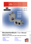
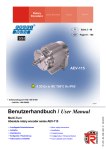
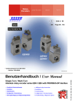
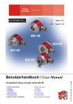
1
Rotary Encoders Linear Encoders System Motion D Seite 2 - 50 GB Page 51 - 100 CK-58 CEK-58 COK-58 CE-58 CEV-58 COV-58 CH-58 / CS-58 CEH-58 / CES-58 COH-58 / COS-58 437696, 437732, 43774A, 437753, 437744 • Zusätzliche Sicherheitshinweise • Installation • Inbetriebnahme • Parametrierung • Fehlerursachen und Abhilfen • Additional safety instructions • Installation • Commissioning • Parameterization • Cause of faults and remedies TR - ECE - BA - DGB - 0039 - 05 Single-Turn / Multi-Turn Absolute rotary encoder series Cxx-58 with SSI interface 10/11/2011 Benutzerhandbuch / User Manual TR-Electronic GmbH D-78647 Trossingen Eglishalde 6 Tel.: (0049) 07425/228-0 Fax: (0049) 07425/228-33 E-mail: [email protected] http://www.tr-electronic.de Urheberrechtsschutz Dieses Handbuch, einschließlich den darin enthaltenen Abbildungen, ist urheberrechtlich geschützt. Drittanwendungen dieses Handbuchs, welche von den urheberrechtlichen Bestimmungen abweichen, sind verboten. Die Reproduktion, Übersetzung sowie die elektronische und fotografische Archivierung und Veränderung bedarf der schriftlichen Genehmigung durch den Hersteller. Zuwiderhandlungen verpflichten zu Schadenersatz. Änderungsvorbehalt Jegliche Änderungen, die dem technischen Fortschritt dienen, vorbehalten. Dokumenteninformation Ausgabe-/Rev.-Datum: Dokument-/Rev.-Nr.: Dateiname: Verfasser: 10/11/2011 TR - ECE - BA - DGB - 0039 - 05 TR-ECE-BA-DGB-0039-05.DOC MÜJ Schreibweisen Kursive oder fette Schreibweise steht für den Titel eines Dokuments oder wird zur Hervorhebung benutzt. Courier-Schrift zeigt Text an, der auf dem Display bzw. Bildschirm sichtbar ist und Menüauswahlen von Software. < > weist auf Tasten der Tastatur Ihres Computers hin (wie etwa <RETURN>). TR-Electronic GmbH 2005, All Rights Reserved Page 2 of 100 Printed in the Federal Republic of Germany TR - ECE - BA - DGB - 0039 - 05 10/11/2011 Inhaltsverzeichnis Inhaltsverzeichnis Inhaltsverzeichnis .............................................................................................................................. 3 Änderungs-Index ................................................................................................................................ 6 1 Allgemeines ..................................................................................................................................... 7 1.1 Geltungsbereich...................................................................................................................... 7 1.2 Verwendete Abkürzungen / Begriffe ....................................................................................... 8 2 Zusätzliche Sicherheitshinweise ................................................................................................... 9 2.1 Symbol- und Hinweis-Definition .............................................................................................. 9 2.2 Organisatorische Maßnahmen ............................................................................................... 9 3 Technische Daten ............................................................................................................................ 10 3.1 Elektrische Kenndaten ............................................................................................................ 10 4 SSI Informationen ............................................................................................................................ 11 5 Installation / Inbetriebnahmevorbereitung ................................................................................... 12 5.1 RS422 Übertragungstechnik .................................................................................................. 12 5.2 Kabelspezifikation ................................................................................................................... 13 5.3 Anschluss ............................................................................................................................... 14 5.3.1 Anbindung an den PC (Programmierung) .............................................................. 15 5.4 SSI Schnittstelle ...................................................................................................................... 16 6 TRWinProg Parametrierung: C_58, CE_58 bis 13 Bit Auflösung ............................................... 17 6.1 Grundparameter ..................................................................................................................... 17 6.1.1 Zählrichtung ............................................................................................................ 17 6.1.2 Skalierungsparameter ............................................................................................. 17 6.1.2.1 Messlänge in Schritten .............................................................................................................. 18 6.1.2.2 Umdrehungen Zähler / Umdrehungen Nenner .......................................................................... 18 6.1.3 Presetwert ............................................................................................................... 21 6.1.4 Presetfreigabe......................................................................................................... 21 6.1.5 Messwertanfang...................................................................................................... 21 6.2 SSI .......................................................................................................................................... 22 6.2.1 Format ..................................................................................................................... 22 6.2.1.1 Tannenbaum Nein (Standard) ................................................................................................... 22 6.2.1.2 Tannenbaum Ja ........................................................................................................................ 23 6.2.1.3 Prüfsumme ................................................................................................................................ 24 6.2.1.4 26-Bit Wiederholung .................................................................................................................. 25 6.2.2 Anzahl Datenbits ..................................................................................................... 27 6.2.3 Ausgabecode .......................................................................................................... 27 6.2.4 Negative Werte ....................................................................................................... 27 6.3 Endschalter ............................................................................................................................. 28 Printed in the Federal Republic of Germany 10/11/2011 TR-Electronic GmbH 2005, All Rights Reserved TR - ECE - BA - DGB - 0039 - 05 Page 3 of 100 Inhaltsverzeichnis 6.4 Sonderbits ............................................................................................................................... 28 6.4.1 Endschalter ............................................................................................................. 28 6.4.2 Überdrehzahl .......................................................................................................... 28 6.4.3 Aufwärts gehen, Abwärts gehen ............................................................................. 28 6.4.4 Aufwärts gegangen ................................................................................................. 29 6.4.5 Bewegung ............................................................................................................... 29 6.4.6 Statischer und dynamischer Fehler (Watchdog) .................................................... 29 6.4.7 Parity gerade, Fehlerparity gerade ......................................................................... 29 6.5 Istwerte ................................................................................................................................... 30 6.5.1 Istwert...................................................................................................................... 30 6.5.2 Umdr/Min ................................................................................................................ 30 7 TRWinProg Parametrierung: CE_58 bis 15 Bit Auflösung .......................................................... 31 7.1 Grundparameter ..................................................................................................................... 31 7.1.1 Zählrichtung ............................................................................................................ 31 7.1.2 Skalierungsparameter ............................................................................................. 31 7.1.2.1 Messlänge in Schritten .............................................................................................................. 31 7.1.2.2 Anzahl Umdrehungen ............................................................................................................... 32 7.1.3 Presetwert ............................................................................................................... 32 7.1.4 Presetfreigabe......................................................................................................... 32 7.2 SSI .......................................................................................................................................... 33 7.2.1 Format ..................................................................................................................... 33 7.2.1.1 Tannenbaum Nein ..................................................................................................................... 33 7.2.1.2 Tannenbaum Ja ........................................................................................................................ 34 7.2.2 Anzahl Datenbits ..................................................................................................... 35 7.2.3 Ausgabecode .......................................................................................................... 35 7.3 Istwerte ................................................................................................................................... 36 7.3.1 Position ................................................................................................................... 36 8 TRWinProg Parametrierung: CO_58 ............................................................................................. 37 8.1 Grundparameter ..................................................................................................................... 37 8.1.1 Zählrichtung ............................................................................................................ 37 8.1.2 Skalierungsparameter ............................................................................................. 37 8.1.2.1 Messlänge in Schritten .............................................................................................................. 38 8.1.2.2 Umdrehungen Zähler / Umdrehungen Nenner .......................................................................... 38 8.1.3 Presetwert ............................................................................................................... 41 8.1.4 Presetfreigabe......................................................................................................... 41 8.1.5 Messwertanfang...................................................................................................... 41 8.2 SSI .......................................................................................................................................... 42 8.2.1 Format ..................................................................................................................... 42 8.2.1.1 Kein Sonderformat .................................................................................................................... 42 8.2.1.2 Parity gerade ............................................................................................................................. 43 8.2.1.3 Parity ungerade ......................................................................................................................... 43 8.2.1.4 Toggelbit ................................................................................................................................... 43 8.2.1.5 Wiederholung mit 1-3 Pausentakten ......................................................................................... 44 8.2.1.6 Prüfsumme 28 nach 25-28 Datenbits ........................................................................................ 45 8.2.2 Anzahl Datenbits ..................................................................................................... 46 8.2.3 Ausgabecode .......................................................................................................... 46 8.2.4 Negative Werte ....................................................................................................... 47 8.2.5 Monozeit ................................................................................................................. 47 TR-Electronic GmbH 2005, All Rights Reserved Page 4 of 100 Printed in the Federal Republic of Germany TR - ECE - BA - DGB - 0039 - 05 10/11/2011 Inhaltsverzeichnis 8.3 Inkremental (optional) ............................................................................................................. 47 8.3.1 Anzahl Impulse ....................................................................................................... 47 8.3.2 Phase K1/K2 ........................................................................................................... 47 8.3.3 Nullimpuls wenn ...................................................................................................... 48 8.4 Position ................................................................................................................................... 49 8.4.1 Position ................................................................................................................... 49 8.4.2 Geschwindigkeit in Umdr/Min ................................................................................. 49 9 Fehlerursachen und Abhilfen......................................................................................................... 50 Printed in the Federal Republic of Germany 10/11/2011 TR-Electronic GmbH 2005, All Rights Reserved TR - ECE - BA - DGB - 0039 - 05 Page 5 of 100 Änderungs-Index Änderungs-Index Änderung Datum Index Erstausgabe 27.07.05 00 14.09.05 01 Angaben zur UL / CSA – Zulassung 12.07.06 02 EMV – Normen angepasst 30.11.09 03 Neue Encoder Baureihe: COV-58, COK-58, COS-58, COH-58 15.03.10 04 Anpassung der Warnhinweise 11.10.11 05 Textanpassungen für Warnhinweis in Kapitel 6 Neue Encoder Baureihe: CEV-58, CEK-58, CES-58, CEH-58 TR-Electronic GmbH 2005, All Rights Reserved Page 6 of 100 Printed in the Federal Republic of Germany TR - ECE - BA - DGB - 0039 - 05 10/11/2011 Allgemeines 1 Allgemeines Das vorliegende schnittstellenspezifische Benutzerhandbuch beinhaltet folgende Themen: Ergänzende Sicherheitshinweise zu den bereits in der Montageanleitung definierten grundlegenden Sicherheitshinweisen Elektrische Kenndaten Installation Inbetriebnahme Parametrierung Fehlerursachen und Abhilfen Da die Dokumentation modular aufgebaut ist, stellt dieses Benutzerhandbuch eine Ergänzung zu anderen Dokumentationen wie z.B. Produktdatenblätter, Maßzeichnungen, Prospekte und der Montageanleitung etc. dar. Das Benutzerhandbuch kann kundenspezifisch im Lieferumfang enthalten sein, oder kann auch separat angefordert werden. 1.1 Geltungsbereich Dieses Benutzerhandbuch gilt ausschließlich für folgende Mess-System-Baureihen mit SSI Schnittstelle: CE-58, CEV-58, COV-58 CH-58, CEH-58, COH-58 CS-58, CES-58, COS-58 CK-58, CEK-58, COK-58 Die Produkte sind durch aufgeklebte Typenschilder gekennzeichnet und sind Bestandteil einer Anlage. Es gelten somit zusammen folgende Dokumentationen: anlagenspezifische Betriebsanleitungen des Betreibers, dieses Benutzerhandbuch, und die bei der Lieferung beiliegende Montageanleitung TR-ECE-BA-DGB-0035 Printed in the Federal Republic of Germany 10/11/2011 TR-Electronic GmbH 2005, All Rights Reserved TR - ECE - BA - DGB - 0039 - 05 Page 7 of 100 Allgemeines 1.2 Verwendete Abkürzungen / Begriffe CE, CEV Absolut-Encoder mit optischer Abtastung Ausführung mit Vollwelle COV Absolut-Encoder mit optischer Abtastung > 15 Bit Auflösung, Ausführung mit Vollwelle CK, CEK Absolut-Encoder mit optischer Abtastung Ausführung mit Kupplung COK Absolut-Encoder mit optischer Abtastung > 15 Bit Auflösung, Ausführung mit Kupplung CS, CES Absolut-Encoder mit optischer Abtastung Ausführung mit Sackloch COS Absolut-Encoder mit optischer Abtastung > 15 Bit Auflösung, Ausführung mit Sackloch CH, CEH Absolut-Encoder mit optischer Abtastung Ausführung mit Hohlwelle COH Absolut-Encoder mit optischer Abtastung > 15 Bit Auflösung, Ausführung mit Hohlwelle CRC Cylic Redundancy Check (Redundanzprüfung) EMV Elektro-Magnetische-Verträglichkeit SSI Synchron-Serielles-Interface LSB Least Significant Bit (niederwertiges Bit) MSB Most Significant Bit (höchstwertiges Bit) NEC National Electrical Code T Periodendauer tM SSI Monozeit tp Pausenzeit tV Verzögerungszeit VZ Vorzeichen 0x Hexadezimale Darstellung TR-Electronic GmbH 2005, All Rights Reserved Page 8 of 100 15 Bit Auflösung, 15 Bit Auflösung, 15 Bit Auflösung, 15 Bit Auflösung, Printed in the Federal Republic of Germany TR - ECE - BA - DGB - 0039 - 05 10/11/2011 Zusätzliche Sicherheitshinweise 2 Zusätzliche Sicherheitshinweise 2.1 Symbol- und Hinweis-Definition bedeutet, dass Tod oder schwere Körperverletzung eintreten kann, wenn die entsprechenden Vorsichtsmaßnahmen nicht getroffen werden. bedeutet, dass eine leichte Körperverletzung eintreten kann, wenn die entsprechenden Vorsichtsmaßnahmen nicht getroffen werden. bedeutet, dass ein Sachschaden eintreten kann, wenn die entsprechenden Vorsichtsmaßnahmen nicht getroffen werden. bezeichnet wichtige Informationen bzw. Merkmale und Anwendungstipps des verwendeten Produkts. 2.2 Organisatorische Maßnahmen Dieses Benutzerhandbuch muss ständig am Einsatzort des Mess-Systems griffbereit aufbewahrt werden. Das mit Tätigkeiten am Mess-System beauftragte Personal muss vor Arbeitsbeginn insbesondere das Kapitel „Grundlegende - die Montageanleitung, Sicherheitshinweise“, - und dieses Benutzerhandbuch, insbesondere das Kapitel „Zusätzliche Sicherheitshinweise“, gelesen und verstanden haben. Dies gilt in besonderem Maße für nur gelegentlich, z. B. bei der Parametrierung des Mess-Systems, tätig werdendes Personal. Printed in the Federal Republic of Germany 10/11/2011 TR-Electronic GmbH 2005, All Rights Reserved TR - ECE - BA - DGB - 0039 - 05 Page 9 of 100 Technische Daten 3 Technische Daten 3.1 Elektrische Kenndaten 11…27 VDC, paarweise verdrillt und geschirmt Versorgungsspannung ..................................... Bei UL / CSA-Zulassung ..................................... Nach NEC Klasse 2; 24 V DC (11-27 V DC) < 350 mA bei 11 V DC, < 180 mA bei 27 V DC Stromaufnahme ohne Last ............................... Gesamtauflösung CEx ...................................................................... 30 Bit COx ..................................................................... 36 Bit * Schrittzahl / Umdrehung CEx, Standard ..................................................... 8.192 CEx, erweitert ...................................................... 32.768 COx ..................................................................... 262.144 * Anzahl Umdrehungen CEx, Standard ..................................................... 4.096 CEx, erweitert ...................................................... 256.000 COx ..................................................................... 256.000 PC IBM kompatibel (TRWinProg) Programmierung über RS485 ........................... Takte und Daten jeweils paarweise verdrillt und geschirmt SSI Schnittstelle ................................................ Takteingang......................................................... Optokoppler Taktfrequenz ....................................................... 80 kHz – 1 MHz * Ausgabecode .................................................... Binär, Gray, BCD Datenausgang ..................................................... RS422 (2-Draht) nach dem EIA-Standard * Anzahl Datenbits ............................................... 36, ohne SSI-Sonderbits * Ausgabeformat.................................................. Standard, Tannenbaum, Prüfsumme, 26-Bit Wiederholung u.a. * negative Werte .................................................. Vorzeichen + Betrag, 2er Komplement * Monozeit tM ....................................................... 16 µs tM 25 µs, typisch 20 µs 250 µs Zykluszeit ........................................................... Push-Pull, max. 8 Parallel-Ausgänge, nur CEx ............................. Ausgangsstrom ................................................... 50 mA, kurzschlussfest (je Ausgang) Eingänge * V/R .................................................................... Zählrichtung * Preset ................................................................ elektronische Justage Schaltpegel.......................................................... „0“ < + 2 V DC, „1“ > + 11 V DC, max. 27 V DC EMV Störfestigkeit........................................................ DIN EN 61000-6-2: 2006 Störaussendung .................................................. DIN EN 61000-6-3: 2007 * parametrierbar über TRWinProg, typspezifische Unterstützung TR-Electronic GmbH 2005, All Rights Reserved Page 10 of 100 Printed in the Federal Republic of Germany TR - ECE - BA - DGB - 0039 - 05 10/11/2011 SSI Informationen 4 SSI Informationen Das SSI-Verfahren ist ein synchron-serielles Übertragungsverfahren für die MessSystem-Position. Durch die Verwendung der RS422 Schnittstelle zur Übertragung können ausreichend hohe Übertragungsraten erzielt werden. Das Mess-System erhält vom Datenempfänger (Steuerung) ein Taktbüschel und antwortet mit dem aktuellen Positionswert, der synchron zum gesendeten Takt seriell übertragen wird. Weil die Datenübernahme durch den Büschelanfang synchronisiert wird, ist es nicht notwendig, einschrittige Codes wie z.B. Graycode zu verwenden. Die Datensignale Daten+ und Daten– werden mit Kabelsendern (RS422) gesendet. Zum Schutz gegen Beschädigungen durch Störungen, Potentialdifferenzen oder Verpolen werden die Taktsignale Takt+ und Takt- mit Optokopplern empfangen. Zur Erkennung von fehlerhaften Übertragungen können Parities oder Prüfsummen hinzugefügt werden. Als einfachste Maßnahme ist auch die doppelte Einlesung möglich, bei der die Datenbits nach jeweils 26 Takten eines Büschels wiederholt werden. Von Nachteil ist aber die stark erhöhte Übertragungsdauer. BAV99 65 SSI-Clock+ +5V Opto-Koppler C 2.2 nF N.C. SSI-Clock- GND 65 C Abbildung 1: SSI Prinzip-Eingangsschaltung D a ta + R S 4 2 2 D a ta - Abbildung 2: SSI-Ausgangsschaltung Printed in the Federal Republic of Germany 10/11/2011 TR-Electronic GmbH 2005, All Rights Reserved TR - ECE - BA - DGB - 0039 - 05 Page 11 of 100 Installation / Inbetriebnahmevorbereitung 5 Installation / Inbetriebnahmevorbereitung 5.1 RS422 Übertragungstechnik Bei der RS422-Übertragung wird ein Leitungspaar für die Signale Daten+ und Daten– und ein Leitungspaar für die Signale Takt+ und Takt– benötigt. Die seriellen Daten werden ohne Massebezug als Spannungsdifferenz zwischen zwei korrespondierenden Leitungen übertragen. Der Empfänger wertet lediglich die Differenz zwischen beiden Leitungen aus, so dass Gleichtakt-Störungen auf der Übertragungsleitung nicht zu einer Verfälschung des Nutzsignals führen. Durch die Verwendung von abgeschirmtem, paarig verseiltem Kabel, lassen sich Datenübertragungen über Distanzen von bis zu 500 Metern bei einer Frequenz von 100 kHz realisieren. RS422-Sender stellen unter Last Ausgangspegel von 2V zwischen den beiden Ausgängen zur Verfügung, die Empfängerbausteine erkennen Pegel von ± 200mV noch als gültiges Signal. TR-Electronic GmbH 2005, All Rights Reserved Page 12 of 100 Printed in the Federal Republic of Germany TR - ECE - BA - DGB - 0039 - 05 10/11/2011 Installation / Inbetriebnahmevorbereitung 5.2 Kabelspezifikation Signal Leitung (z.B. TR Art.-Nr.: 64-200-021) Daten+ / Daten– (RS422+ / RS422–) Takt+ / Takt– (RS422+ / RS422–) min. 0,25mm2, jeweils paarig verseilt und geschirmt Programmierschnittstelle (RS485+ / RS485–) min. 0,5mm2, paarig verseilt und geschirmt Versorgung Die maximale Leitungslänge hängt von der SSI-Taktfrequenz und der Kabelbeschaffenheit ab und sollte an folgende Tabelle angepasst werden. Zu beachten ist, dass pro Meter Kabel mit einer zusätzlichen Verzögerungszeit tv (Daten+/Daten–) von ca. 6ns zu rechnen ist. SSI-Taktfrequenz [kHz] Leitungslänge [m] 810 750 570 360 220 120 100 ca. 12.5 ca. 25 ca. 50 ca. 100 ca. 200 ca. 400 ca. 500 Um eine hohe Störfestigkeit des Systems gegen elektromagnetische Störstrahlungen zu erzielen, muss eine geschirmte Datenleitung verwendet werden. Der Schirm sollte möglichst beidseitig und gut leitend über großflächige Schirmschellen an Schutzerde angeschlossen werden. Nur wenn die Maschinenerde gegenüber der Schaltschrankerde stark mit Störungen behaftet ist, sollte man den Schirm einseitig im Schaltschrank erden. Weiterhin ist zu beachten, dass die Daten- und Taktleitungen möglichst separat von allen starkstromführenden Kabeln verlegt werden. Um einen sicheren und störungsfreien Betrieb zu gewährleisten, sind die einschlägigen Normen und Richtlinien zu beachten! Insbesondere sind die EMV-Richtlinie sowie die Schirmungs- und Erdungsrichtlinien in den jeweils gültigen Fassungen zu beachten! Printed in the Federal Republic of Germany 10/11/2011 TR-Electronic GmbH 2005, All Rights Reserved TR - ECE - BA - DGB - 0039 - 05 Page 13 of 100 Installation / Inbetriebnahmevorbereitung 5.3 Anschluss Die Steckerbelegung ist abhängig von der Geräteausführung und ist deshalb bei jedem Mess-System auf dem Typenschild als Steckerbelegungsnummer vermerkt. Bei der Auslieferung des Mess-Systems wird jeweils eine gerätespezifische Steckerbelegung in gedruckter Form beigelegt. Nachfolgend sind als exemplarisches Beispiel die Signalnamen aufgeführt: M = Mandatory (zwingend) O = Optional Bezeichnung Beschreibung Pegel M/O SSI_Clock– IN Takteingang– RS422 M SSI_Clock+ IN Takteingang+ RS422 M SSI_Data+ OUT Datenausgang+ RS422 M SSI_Data– OUT Datenausgang– RS422 M Ser.Program+ IN/OUT Programmierung RS485 O Ser.Program– IN/OUT Programmierung RS485 O Direction IN Zählrichtungsänderung 11-27 V DC O Preset1 IN Vorgabewert 1 11-27 V DC O Preset2 IN Vorgabewert 2 11-27 V DC O Output D0 Out Parallel-Ausgang 1 11-27 V DC O Output D1 Out Parallel-Ausgang 2 11-27 V DC O Output D2 Out Parallel-Ausgang 3 11-27 V DC O Output D3 Out Parallel-Ausgang 4 11-27 V DC O Output D4 Out Parallel-Ausgang 5 11-27 V DC O Output D5 Out Parallel-Ausgang 6 11-27 V DC O Output D6 Out Parallel-Ausgang 7 11-27 V DC O Output D7 Out Parallel-Ausgang 8 11-27 V DC O Versorgungsspannung IN Versorgungsspannung 11-27 V DC M GND IN Ground 0V M TR-Electronic GmbH 2005, All Rights Reserved Page 14 of 100 Printed in the Federal Republic of Germany TR - ECE - BA - DGB - 0039 - 05 10/11/2011 Installation / Inbetriebnahmevorbereitung 5.3.1 Anbindung an den PC (Programmierung) Was wird von TR-Electronic benötigt? Schaltschrankmodul Art.-Nr.: 490-00101 Programmier-Set Art.-Nr.: 490-00310: Kunststoff-Koffer, mit nachfolgenden Komponenten: – USB PC-Adapter V4 Umsetzung USB <--> RS485 – USB-Kabel 1,00 m Verbindungskabel zwischen PC-Adapter und PC – Flachbandkabel 1,30 m Verbindungskabel zwischen PC-Adapter und TR-Schaltschrank-Modul (15-pol. SUB-D Buchse/Stecker) – Steckernetzteil 24 V DC, 1A Versorgungsmöglichkeit des angeschlossenen Gerätes über den PC-Adapter – Software- und Support-CD - USB-Treiber, Soft-Nr.: 490-00421 - TRWinProg, Soft-Nr.: 490-00416 - EPROGW32, Soft-Nr.: 490-00418 - LTProg, Soft-Nr.: 490-00415 – Installationsanleitung TR-E-TI-DGB-0074, Deutsch/Englisch Printed in the Federal Republic of Germany 10/11/2011 TR-Electronic GmbH 2005, All Rights Reserved TR - ECE - BA - DGB - 0039 - 05 Page 15 of 100 Installation / Inbetriebnahmevorbereitung 5.4 SSI Schnittstelle Im Ruhezustand liegen Daten+ und Takt+ auf High. Dies entspricht der Zeit vor Punkt (1) im unten angegebenen Schaubild. Mit dem ersten Wechsel des Takt-Signals von High auf Low (1) wird das Geräteinterne re-triggerbare Monoflop mit der Monoflopzeit tM gesetzt. Die Zeit tM bestimmt die unterste Übertragungsfrequenz (T = tM / 2). Die obere Grenzfrequenz ergibt sich aus der Summe aller Signallaufzeiten und wird zusätzlich durch die eingebauten Filterschaltungen begrenzt. Mit jeder weiteren fallenden Taktflanke verlängert sich der aktive Zustand des Monoflops um die Zeit tM, zuletzt ist dies bei Punkt (4) der Fall. Mit dem Setzen des Monoflops (1) werden die am internen Parallel-Seriell-Wandler anstehenden bit-parallelen Daten durch ein intern erzeugtes Signal in einem Eingangs-Latch des Schieberegisters gespeichert. Damit ist sichergestellt, dass sich die Daten während der Übertragung eines Positionswertes nicht mehr verändern. Mit dem ersten Wechsel des Taktsignals von Low auf High (2) wird das höchstwertige Bit (MSB) der Geräteinformation an den seriellen Datenausgang gelegt. Mit jeder weiteren steigenden Flanke wird das nächst niederwertigere Bit an den Datenausgang geschoben. Nach beendeter Taktfolge werden die Datenleitungen für die Dauer der Monozeit tM (4) auf 0V (Low) gehalten. Dadurch ergibt sich auch die Pausenmindestzeit tp, die zwischen zwei aufeinanderfolgenden Taktsequenzen eingehalten werden muss und beträgt 2 * tM. Bereits mit der ersten steigenden Taktflanke werden die Daten von der Auswerteelektronik eingelesen. Bedingt durch verschiedene Faktoren ergibt sich eine Verzögerungszeit tV >100ns, ohne Kabel. Das Mess-System schiebt dadurch die Daten um die Zeit tV verzögert an den Ausgang. Zum Zeitpunkt (2) wird deshalb eine „Pausen-1“ gelesen. Diese muss verworfen werden oder kann in Verbindung mit einer „0“ nach dem LSB-Datenbit zur Leitungsbruchüberwachung benutzt werden. Erst zum Zeitpunkt (3) wird das MSB-Datenbit gelesen. Aus diesem Grund muss die Taktanzahl immer um eins höher sein (n+1) als die zu übertragende Anzahl der Datenbits. tp Monoflopzeit Takt+ Daten+ Abbildung 3: Typische SSI-Übertragungssequenzen 1 Takt+ Daten+ 2 3 1 4 T 2 MSB n+1 n tM LSB High Low High Low tV High Low intern re-triggerbares Monoflop Abbildung 4: SSI-Übertragungsformat TR-Electronic GmbH 2005, All Rights Reserved Page 16 of 100 Printed in the Federal Republic of Germany TR - ECE - BA - DGB - 0039 - 05 10/11/2011 TRWinProg Parametrierung: C_58, CE_58 bis 13 Bit Auflösung 6 TRWinProg Parametrierung: C_58, CE_58 bis 13 Bit Auflösung Gefahr von Körperverletzung und Sachschaden beim Wiedereinschalten des Mess-Systems nach Positionierungen im stromlosen Zustand durch Verschiebung des Nullpunktes! Ist die Anzahl der Umdrehungen keine 2-er Potenz oder >4096, kann, falls mehr als 512 Umdrehungen im stromlosen Zustand ausgeführt werden, der Nullpunkt des Multi-Turn Mess-Systems verloren gehen! Sicherstellen, dass bei einem Multi-Turn Mess-System der Quotient von Umdrehungen Zähler/Umdrehungen Nenner eine 2er-Potenz aus der Menge 20, 21, 22…212 (1, 2, 4…4096) ist. oder Sicherstellen, dass sich Positionierungen im stromlosen Zustand bei einem Multi-Turn Mess-System innerhalb von 512 Umdrehungen befinden. 6.1 Grundparameter 6.1.1 Zählrichtung Auswahl Beschreibung Default Steigend Mess-System – Position im Uhrzeigersinn steigend (Blick auf Anflanschung) Fallend Mess-System – Position im Uhrzeigersinn fallend (Blick auf Anflanschung) X 6.1.2 Skalierungsparameter Über die Skalierungsparameter kann die physikalische Auflösung des Mess-Systems verändert werden. Das Mess-System unterstützt die Getriebefunktion für Rundachsen. Dies bedeutet, dass die Anzahl Schritte pro Umdrehung und der Quotient von Umdrehungen Zähler/Umdrehungen Nenner eine Kommazahl sein darf. Der ausgegebene Positionswert wird mit einer Nullpunktskorrektur, der eingestellten Zählrichtung und den eingegebenen Getriebeparametern verrechnet. Printed in the Federal Republic of Germany 10/11/2011 TR-Electronic GmbH 2005, All Rights Reserved TR - ECE - BA - DGB - 0039 - 05 Page 17 of 100 TRWinProg Parametrierung: C_58, CE_58 bis 13 Bit Auflösung 6.1.2.1 Messlänge in Schritten Legt die Gesamtschrittzahl des Mess-Systems fest, bevor der Mess-System wieder bei Null beginnt. Untergrenze 2 Schritte Obergrenze 1 073 741 824 Schritte (30 Bit) Default 16 777 216 Der tatsächlich einzugebende Obergrenzwert für die Messlänge in Schritten ist von der Mess-System-Ausführung abhängig und kann nach untenstehender Formel berechnet werden. Da der Wert „0“ bereits als Schritt gezählt wird, ist der Endwert = Messlänge in Schritten – 1. Messlänge in Schritten = Schritte pro Umdrehung * Anzahl der Umdrehungen Zur Berechnung können die Parameter Schritte/Umdr. und Anzahl Umdrehungen vom Typenschild des Mess-Systems abgelesen werden. 6.1.2.2 Umdrehungen Zähler / Umdrehungen Nenner Diese beiden Parameter zusammen legen die Anzahl der Umdrehungen fest, bevor das Mess-System wieder bei Null beginnt. Da Kommazahlen nicht immer endlich (wie z.B. 3,4) sein müssen, sondern mit unendlichen Nachkommastellen (z.B. 3,43535355358774... ) behaftet sein können, wird die Umdrehungszahl als Bruch eingegeben. Der Bruch darf jedoch nicht kleiner als 0,5 sein. Untergrenze Zähler 1 Obergrenze Zähler 256000 Default Zähler 4096 Untergrenze Nenner 1 Obergrenze Nenner 16384 Default Nenner 1 Formel für Getriebeberechnung: Messlänge in Schritten = Anzahl Schritte pro Umdrehung * TR-Electronic GmbH 2005, All Rights Reserved Page 18 of 100 Anzahl Umdrehungen Zähler Anzahl Umdrehungen Nenner Printed in the Federal Republic of Germany TR - ECE - BA - DGB - 0039 - 05 10/11/2011 TRWinProg Parametrierung: C_58, CE_58 bis 13 Bit Auflösung Sollten bei der Eingabe der Parametrierdaten die zulässigen Bereiche von Zähler und Nenner nicht eingehalten werden können, muss versucht werden diese entsprechend zu kürzen. Ist dies nicht möglich, kann die entsprechende Kommanzahl möglicherweise nur annähernd dargestellt werden. Die sich ergebende kleine Ungenauigkeit wird bei echten Rundachsenanwendungen (Endlos-Anwendungen in eine Richtung fahrend) mit der Zeit aufaddiert. Zur Abhilfe kann z.B. nach jedem Umlauf eine Justage durchgeführt werden, oder man passt die Mechanik bzw. Übersetzung entsprechend an. Der Parameter „Anzahl Schritte pro Umdrehung“ darf ebenfalls eine Kommazahl sein, jedoch nicht die „Messlänge in Schritten“. Das Ergebnis aus obiger Formel muss auf bzw. abgerundet werden. Der dabei entstehende Fehler verteilt sich auf die programmierte gesamte Umdrehungsanzahl und ist somit vernachlässigbar. Vorgehensweise bei Linearachsen (Vor- und Zurück-Verfahrbewegungen): Der Parameter „Umdrehungen Nenner“ kann bei Linearachsen fest auf „1“ programmiert werden. Der Parameter „Umdrehungen Zähler“ wird etwas größer als die benötigte Umdrehungsanzahl programmiert. Somit ist sichergestellt, dass das Mess-System bei einer geringfügigen Überschreitung des Verfahrweges keinen Istwertsprung (Nullübergang) erzeugt. Der Einfachheit halber kann auch der volle Umdrehungsbereich des Mess-Systems programmiert werden. Das folgende Beispiel soll die Vorgehensweise näher erläutern: Gegeben: - Mess-System mit 4096 Schritte/Umdr. und max. 4096 Umdrehungen - Auflösung 1/100 mm - Sicherstellen, dass das Mess-System in seiner vollen Auflösung und Messlänge (4096x4096) programmiert ist: Messlänge in Schritten = 16777216, Umdrehungen Zähler = 4096 Umdrehungen Nenner = 1 Zu erfassende Mechanik auf Linksanschlag bringen - Mess-System mittels Justage auf „0“ setzen - Zu erfassende Mechanik in Endlage bringen - Den mechanisch zurückgelegten Weg in mm vermessen - Istposition des Mess-Systems an der angeschlossenen Steuerung ablesen Printed in the Federal Republic of Germany 10/11/2011 TR-Electronic GmbH 2005, All Rights Reserved TR - ECE - BA - DGB - 0039 - 05 Page 19 of 100 TRWinProg Parametrierung: C_58, CE_58 bis 13 Bit Auflösung Annahme: - zurückgelegter Weg = 2000 mm Mess-Sysem-Istposition nach 2000 mm = 607682 Schritte Daraus folgt: Anzahl zurückgelegter Umdrehungen = 607682 Schritte / 4096 Schritte/Umdr. = 148,3598633 Umdrehungen Anzahl mm / Umdrehung = 2000 mm / 148,3598633 Umdr. = 13,48073499mm / Umdr. Bei 1/100mm Auflösung entspricht dies einer Schrittzahl / Umdrehung von 1348,073499 erforderliche Programmierungen: Anzahl Umdrehungen Zähler = 4096 Anzahl Umdrehungen Nenner = 1 Messlänge in Schritten = Anzahl Schritte pro Umdrehung * = 1348,073499 Schritte / Umdr. * Anzahl Umdrehungen Zähler Anzahl Umdrehungen Nenner 4096 Umdrehungen Zähler 1 Umdrehung Nenner = 5521709 Schritte (abgerundet) TR-Electronic GmbH 2005, All Rights Reserved Page 20 of 100 Printed in the Federal Republic of Germany TR - ECE - BA - DGB - 0039 - 05 10/11/2011 TRWinProg Parametrierung: C_58, CE_58 bis 13 Bit Auflösung 6.1.3 Presetwert Festlegung des Positionswertes, auf welchen das Mess-System justiert wird, wenn die Preset-Justage-Funktion durch Beschalten des Preset-Eingangs ausgeführt wird. Programmierter Messwertanfang Presetwert < Programmierte Messlänge in Schritten Untergrenze –1 073 741 824 Obergrenze 1 073 741 823 Default 0 6.1.4 Presetfreigabe Gefahr von Körperverletzung und Sachschaden durch einen Istwertsprung bei Ausführung der Preset-Justage-Funktion! Die Preset-Justage-Funktion sollte nur im Mess-System-Stillstand ausgeführt werden, bzw. muss der resultierende Istwertsprung programmtechnisch und anwendungstechnisch erlaubt sein! Werden die Preset-Eingänge nicht benötigt, sollten sie zur Störunterdrückung gesperrt werden. Auswahl Beschreibung freigegeben Preset-Justage-Funktion aktiv gesperrt Preset-Justage-Funktion inaktiv Default kundenspezifisch 6.1.5 Messwertanfang Festlegung des Mess-System-Anfangswertes (Zählbeginn). Ein von „0“ unterschiedlicher Wert bewirkt eine Nullpunktverschiebung und es entsteht ein negativer oder positiver Offset. Ist ein negativer Messanfang definiert worden, muss im Abschnitt „SSI“ die Darstellungsart (2er-Komplement oder Vorzeichen und Betrag) für die negativen Werte festgelegt werden. Untergrenze –1 073 741 824 Obergrenze 1 073 741 824 Default 0 Printed in the Federal Republic of Germany 10/11/2011 TR-Electronic GmbH 2005, All Rights Reserved TR - ECE - BA - DGB - 0039 - 05 Page 21 of 100 TRWinProg Parametrierung: C_58, CE_58 bis 13 Bit Auflösung 6.2 SSI 6.2.1 Format 6.2.1.1 Tannenbaum Nein (Standard) Tannenbaum Nein = Default-Einstellung Eine synchron-serielle Datenübertragung ohne Tannenbaumformat ist min. 8 Bit, bzw. max. 32 Bit breit. Die Datenübertragung beginnt mit dem höchstwertigen Bit (MSB) und enthält die Positionsbits (P) und max. 8 frei programmierbare SSI-Sonderbits (S). Die SSI-Sonderbits werden nach dem LSB-Positionsbit angehängt. In der DefaultEinstellung sind die SSI-Sonderbits auf „ständig 0V“ programmiert und erzeugen, wenn sie zum Tragen kommen, nachlaufende „Nullen“. Die Daten können beliebig, bezogen auf das Beispiel von 32 Takten, durch den Parameter Anzahl Datenbits verschoben werden. Die Daten können rechts - oder linksbündig, mit und ohne führende „Nullen“ übertragen werden. Führende „Nullen“ werden erzeugt, indem der Parameter Anzahl Datenbits größer programmiert wird, als dies von der Gesamtmesslänge her nötig wäre. Der Parameter Anzahl Datenbits unter dem Abschnitt SSI repräsentiert die Anzahl der ausgegebenen Positionsbits ohne die SSI-Sonderbits ! Beispiel Mess-System: 1024 Schritte/Umdrehung (10 Bits) 4096 Umdrehungen (12 Bits) --> Gesamtmesslänge = 22 Bits Code: Binär oder Gray Ausgabe rechtsbündig Programmierte Anzahl Datenbits = 24 MSB LSB 1 2 3 – 24 25 26 27 28 29 30 31 32 0 0 P 221 – P 20 S1 S2 S3 S4 S5 S6 S7 S8 Ausgabe linksbündig Programmierte Anzahl Datenbits = 22 MSB LSB 1 – 22 23 24 25 26 27 28 29 30 31 32 P 221 – P 20 S1 S2 S3 S4 S5 S6 S7 S8 0 0 TR-Electronic GmbH 2005, All Rights Reserved Page 22 of 100 Printed in the Federal Republic of Germany TR - ECE - BA - DGB - 0039 - 05 10/11/2011 TRWinProg Parametrierung: C_58, CE_58 bis 13 Bit Auflösung 6.2.1.2 Tannenbaum Ja Eine synchron-serielle Datenübertragung mit Tannenbaumformat wird aufgeteilt in Positionsbits (P) für die Anzahl Umdrehungen (links der Mittelachse) und in Positionsbits für die Schrittzahl pro Umdrehung (rechts der Mittelachse). Unabhängig von der programmierten Umdrehungszahl werden für die Anzahl Umdrehungen immer 12 Bits ausgegeben. Programmierungen > 12 Bit sind nicht zulässig. Abhängig von der programmierten Auflösung werden für die Schrittzahl pro Umdrehung max. 13 Bits ausgegeben. Damit lassen sich max. 8192 Schritte/Umdrehung x 4096 Umdrehungen übertragen. Nach dem LSB-Positionsbit werden max. 8 frei programmierbare SSI-Sonderbits (S) angehängt. In der Default-Einstellung sind die SSI-Sonderbits auf „ständig 0V“ programmiert und erzeugen, wenn sie zum Tragen kommen, nachlaufende „Nullen“. Führende „Nullen“ werden erzeugt, wenn für Umdrehungen weniger als 12 Bit benötigt werden. die programmierte Anzahl Die für die programmierte Gesamtmesslänge erforderliche Anzahl Datenbits muss exakt eingetragen werden. Bei der Übertragung der Programmierung an das Mess-System wird die dafür erforderliche Anzahl Datenbits errechnet und mit dem eingetragenen Wert verglichen. Liegt eine Differenz vor, wird der vom Programm errechnete Wert angezeigt. Mit der Übernahme des Wertes wird der falsch eingetragene Wert überschrieben. Einschränkungen: Die Schrittzahl pro Umdrehung muss eine 2er-Potenz sein Messwertanfang = 0 Es kann nur Binär- oder Graycode benutz werden Beispiel 1 (auf 32 Takte bezogen) Mess-System: 8192 Schritte/Umdrehung (13 Bits) 4096 Umdrehungen (12 Bits) --> Gesamtmesslänge = 25 Bits, dies entspricht 25 Datenbits MSB LSB 1 – 12 13 – 25 26 27 28 29 30 31 32 P 224 – P 213 P 212 – P 20 S1 S2 S3 S4 S5 S6 S7 Anzahl Umdrehungen Schrittzahl pro Umdrehung Printed in the Federal Republic of Germany 10/11/2011 TR-Electronic GmbH 2005, All Rights Reserved TR - ECE - BA - DGB - 0039 - 05 Page 23 of 100 TRWinProg Parametrierung: C_58, CE_58 bis 13 Bit Auflösung (auf 32 Takte bezogen) Beispiel 2 Mess-System: 1024 Schritte/Umdrehung (10 Bits) 512 Umdrehungen (9 Bits) --> Gesamtmesslänge = 19 Bits, dies entspricht 19 Datenbits MSB LSB 1 2 3 0 0 0 4 – 12 13 – 22 23 24 25 26 27 28 29 30 31 32 P 218 – P 210 P 29 – P 20 S1 S2 S3 S4 S5 S6 S7 S8 0 0 Anzahl Umdrehungen Schrittzahl pro Umdrehung 6.2.1.3 Prüfsumme Die Auswahl „Prüfsumme“ bewirkt, dass das Mess-System seine Daten im TReigenen SSI-Format überträgt: 28 Datenbits ohne SSI-Sonderbits im Binärcode (MSB-Bit zuerst) Anzahl Umdrehungen = 12 Bit, Schrittzahl pro Umdrehung = 16 Bit, dies entspricht einer max. Gesamtmesslänge von 65536 Schritte/Umdrehung x 4096 Umdrehungen 15 Prüfsummenbits (MSB-Bit zuerst) MSB LSB 1 – 12 13 – 28 29 – 43 P 227 – P 216 P 215 – P 20 CRC 214 – CRC 20 12 Bit Anzahl Umdrehungen 16 Bit Schrittzahl pro Umdrehung 15 Bit TR-Prüfsumme Das Übertragungsformat mit Prüfsumme arbeitet mit einer Hammingdistanz von 6 und erkennt auf diese Weise bis zu 5 Fehler je Codewort. Zudem lassen sich unterbrochene Takt- oder Datenleitungen im Empfangsgerät erkennen. Als Empfangsgeräte (SSI-Master) dienen TR-eigene Applikations-Module, wie z.B. die Achskassette „AK-41“. Wegen der hohen Störsicherheit bei diesem Übertragungsformat, wird diese Technik z.B. in elektrisch stark „verseuchter“ Umgebung mit langen Verbindungswegen eingesetzt. TR-Electronic GmbH 2005, All Rights Reserved Page 24 of 100 Printed in the Federal Republic of Germany TR - ECE - BA - DGB - 0039 - 05 10/11/2011 TRWinProg Parametrierung: C_58, CE_58 bis 13 Bit Auflösung Programmierungen < 12 Bit für die Anzahl Umdrehungen erzeugen führende „Nullen“, Programmierungen < 16 Bit für die Schrittzahl pro Umdrehung erzeugen nachlaufende „Nullen“. Die für die programmierte Gesamtmesslänge erforderliche Anzahl Datenbits muss exakt eingetragen werden. Als Übertragungscode muss Binär ausgewählt werden. Beispiel Mess-System: 4096 Schritte/Umdrehung (12 Bits) 1024 Umdrehungen (10 Bits) --> Gesamtmesslänge = 22 Bits, dies entspricht 22 Datenbits Code: Binär MSB LSB 1 2 3 – 12 13 – 24 25 26 27 28 29 – 43 0 0 P 221 – P 212 P 211 – P 20 0 0 0 0 CRC 214 – CRC 20 12 Bit Anzahl Umdrehungen 16 Bit Schrittzahl pro Umdrehung 15 Bit TR-Prüfsumme 6.2.1.4 26-Bit Wiederholung Mit der Programmierung „26-Bit Wiederholung“ wird mit dem zweiten Taktbüschel Takt 27 bis Takt 52 der gespeicherte Positionswert nochmals übertragen und dient zur Erkennung von Übertragungsfehlern. Ein weiteres Taktbüschel von 26 Takten überträgt ein neues aktualisiertes Datenwort. Ein Datenwort wird also immer nur einmal wiederholt. Folgt der Takt 27 nach einer Zeit die größer als die Standard-Monozeit von 20 μs ist, wird ebenfalls ein neues aktualisiertes Datenwort gesendet. Die Gesamtzahl der Anzahl Datenbits und SSI-Sonderbits darf 26 nicht überschreiten. Eine synchron-serielle Datenübertragung mit 26-Bit Wiederholung ist immer 26 Bit breit. Die Datenübertragung beginnt mit dem höchstwertigen Bit (MSB) und enthält die Positionsbits (P) und max. 8 frei programmierbare SSI-Sonderbits (S). Die SSISonderbits werden nach dem LSB-Positionsbit angehängt. In der Default-Einstellung sind die SSI-Sonderbits auf „ständig 0V“ programmiert und erzeugen, wenn sie zum Tragen kommen, bis zum 26. Takt nachlaufende „Nullen“. Printed in the Federal Republic of Germany 10/11/2011 TR-Electronic GmbH 2005, All Rights Reserved TR - ECE - BA - DGB - 0039 - 05 Page 25 of 100 TRWinProg Parametrierung: C_58, CE_58 bis 13 Bit Auflösung Die Daten können innerhalb der 26 Takte beliebig durch den Parameter Anzahl Datenbits verschoben werden. Die Daten können rechts - oder linksbündig, mit und ohne führende „Nullen“ übertragen werden. Führende „Nullen“ werden erzeugt, indem der Parameter Anzahl Datenbits größer programmiert wird, als dies von der Gesamtmesslänge her nötig wäre. Der Parameter Anzahl Datenbits unter dem Abschnitt SSI repräsentiert die Anzahl der ausgegebenen Positionsbits ohne die SSI-Sonderbits ! Beispiel Mess-System: 1024 Schritte/Umdrehung (10 Bits) 4096 Umdrehungen (12 Bits) --> Gesamtmesslänge = 22 Bits Code: Binär oder Gray Ausgabe rechtsbündig Programmierte Anzahl Datenbits = 24 MSB LSB MSB 1 2 3 – 24 0 0 P 221 – P 20 LSB 26 1 2 3 – 24 S1 S2 0 0 P 221 – P 20 25 Datenwort 1 25 26 S1 S2 Datenwort 2 Ausgabe linksbündig Programmierte Anzahl Datenbits = 22 MSB LSB MSB 1 – 22 23 P 221 – P 20 24 25 26 S1 S2 S3 S4 Datenwort 1 TR-Electronic GmbH 2005, All Rights Reserved Page 26 of 100 LSB 1 – 22 23 P 221 – P 20 24 25 26 S1 S2 S3 S4 Datenwort 2 Printed in the Federal Republic of Germany TR - ECE - BA - DGB - 0039 - 05 10/11/2011 TRWinProg Parametrierung: C_58, CE_58 bis 13 Bit Auflösung 6.2.2 Anzahl Datenbits Der Parameter Anzahl Datenbits legt die Anzahl der reservierten Bits für die Mess-System-Position fest. Sonderbits sind darin nicht enthalten und werden nach den Datenbits ausgegeben. Im Übertragungsformat „Tannenbaum Nein“ und „26-Bit Wiederholung“ wird damit die Lage des 20-Positionsbits zum MSB-Bit festgelegt. Die Übertragungsformate „Tannenbaum Ja“ und „Prüfsumme“ erfordern eine genaue Angabe der Datenbits, entsprechend der programmierten Gesamtmesslänge. Untergrenze 8 Obergrenze 32 Default 24 Formatbedingte Einschränkungen - Prüfsumme: 26-Bit Wiederholung: max. Anzahl Datenbits max. Anzahl Datenbits 28 26 6.2.3 Ausgabecode Auswahl Beschreibung Default Binär SSI-Ausgabecode = Binär Gray SSI-Ausgabecode = Gray BCD SSI-Ausgabecode = BCD X 6.2.4 Negative Werte Auswahl Beschreibung Default 2er Komplement –Maximalwert/2 bis +Maximalwert/2 – 1 Vorzeichen (VZ) + Betrag VZ=1 Maximalwert/2 – 1 bis VZ=0 Maximalwert/2 – 1 X Bei negativen Zahlen ist bei beiden Darstellungen das höchstwertige Positionsbit gesetzt, welches als Vorzeichen benutzt wird. Damit der Zahlenbereich dadurch nicht eingeschränkt wird, wird ein zusätzliches Datenbit benötigt. In der folgenden Tabelle sind Komplement- und Vorzeichendarstellung für Binär- und BCD-Code mit 16 Bit gegenübergestellt: Wert Binär + Komplement Binär + VZ BCD + Komplement BCD + VZ 2 1 0 -1 -2 -3 0x0002 0x0001 0x0000 0xFFFF 0xFFFE 0xFFFD 0x0002 0x0001 0x0000 0x8001 0x8002 0x8003 0x0002 0x0001 0x0000 0x9999 0x9998 0x9997 0x0002 0x0001 0x0000 0x8001 0x8002 0x8003 Printed in the Federal Republic of Germany 10/11/2011 TR-Electronic GmbH 2005, All Rights Reserved TR - ECE - BA - DGB - 0039 - 05 Page 27 of 100 TRWinProg Parametrierung: C_58, CE_58 bis 13 Bit Auflösung 6.3 Endschalter Unter „Endschalter“ werden die erlaubte Höchstdrehzahl des Drehzahlwächters und die Ein- und Ausschaltpunkte der 4 möglichen Endschalter eingestellt. Die Endschalter und der Drehzahlwächter können als Sonderbits auf den ParallelAusgängen und/oder auf der SSI-Schnittstelle ausgegeben werden, siehe nachfolgenden Abschnitt. Die Höchstdrehzahl muss sich im Bereich von 30 bis 6000 min-1 befinden, die DefaultEinstellung ist 6000 min-1. 6.4 Sonderbits Es können max. 8 parallele Sonderbits, bzw. SSI-Sonderbits definiert werden, die Default-Einstellung ist „ständig 0V“. Bedingt durch die kundenspezifischen Geräteausführungen können auch entsprechend weniger parallele Sonderbits auf der Steckerbelegung aufgelegt sein. Die Anzahl der SSI-Sonderbits ist abhängig von den gewählten SSI-Einstellungen und der gesendeten Taktanzahl. Die Sonderbits werden im SSI-Protokoll nach dem niederwertigen Datenbit angehängt. Nachfolgend werden die möglichen Funktionen für die Sonderbits angegeben. Für ein auftretendes Ereignis einer Funktion kann über die Auswahl aktiv high / aktiv low der Ausgangspegel festgelegt werden. 6.4.1 Endschalter Das Sonderbit Endschalter wird gesetzt, solange die Position auf, oder über dem Einschaltpunkt liegt. Es können auch „umlaufende“ Endschalter realisiert werden, dabei ist der Einschaltpunkt größer als der Ausschaltpunkt. Die Schaltpunkte werden oben im Abschnitt „6.3 Endschalter“ eingegeben. 6.4.2 Überdrehzahl Das Sonderbit Überdrehzahl wird gesetzt, wenn die oben im Abschnitt „6.3 Endschalter“ eingestellte Höchstdrehzahl überschritten wird. 6.4.3 Aufwärts gehen, Abwärts gehen Es handelt sich um eine Kombination von Richtungsanzeige und Stillstandswächter. Das Sonderbit wird gesetzt, wenn die Position sich in die entsprechende Richtung bewegt, und gelöscht, sobald sie 50 Millisekunden unverändert bleibt. Die Bewegungserkennung hat zur Unterdrückung von Vibrationen eine Hysterese. Diese beträgt einen Schritt bezogen auf die Auflösung der Zentralscheibe. Nach einer Laufrichtungsumkehr muss mindestens ein der Hysterese entsprechender Weg gefahren werden, bevor eine Bewegung oder Richtungsänderung gemeldet wird. Die Hysterese gilt auch für die nachfolgend geschilderten Signale Aufwärts gegangen und Bewegung. TR-Electronic GmbH 2005, All Rights Reserved Page 28 of 100 Printed in the Federal Republic of Germany TR - ECE - BA - DGB - 0039 - 05 10/11/2011 TRWinProg Parametrierung: C_58, CE_58 bis 13 Bit Auflösung 6.4.4 Aufwärts gegangen Das Sonderbit wird gesetzt, wenn Aufwärts gehen gesetzt wird, und gelöscht, wenn Abwärts gehen gesetzt wird. 6.4.5 Bewegung Das Sonderbit ist gesetzt, solange entweder Aufwärts gehen oder Abwärts gehen gesetzt ist. 6.4.6 Statischer und dynamischer Fehler (Watchdog) Solange die Positionsdaten fehlerfrei gemessen und übertragen werden können, ist das Sonderbit Statischer Fehler gelöscht und das Sonderbit Dynamischer Fehler liefert eine Rechteckfrequenz von 250 Hz. Im Fehlerfall wird der Statische Fehler gesetzt und der Dynamische Fehler bleibt auf irgendeinem Pegel stehen. Nach Möglichkeit sollte der dynamische statt dem statischen Fehler verwendet werden, weil damit auch ein fehlerhafter Programmablauf im Gerät mit sehr hoher Wahrscheinlichkeit erkannt werden kann. Folgende Fehler werden gemeldet: Satelliten-Abtastfehler (internes Getriebe) EEPROM-Lesefehler Flash-Löschfehler Flash-Schreibfehler Ist der Fehler behoben, kann der Fehler über den Eingang „Preset“, oder durch Ausschalten und anschließendem Wiedereinschalten der Spannungsversorgung gelöscht werden. 6.4.7 Parity gerade, Fehlerparity gerade Das Paritybit dient als Kontrollbit zur Fehlererkennung bei der SSI-Datenübertragung. Die Parität stellt die Quersumme der Bits im SSI-Datenwort dar. Enthält das SSIDatenwort eine ungerade Anzahl von Einsen, ist das Sonderbit Parity gerade = „1“ und ergänzt die Quersumme auf gerade Parität. Deshalb muss das Parity- bzw. Fehlerparity-Sonderbit immer an letzter Stelle definiert werden. Es wird aus allen vorausgehenden Bits berechnet. Daher ist auch nur ein einziges Parity-Sonderbit möglich. Durch Auswahl des invertierten Parity erhält man das Parity ungerade bzw. Fehlerparity ungerade. Das Fehlerparity entspricht dem normalen Parity, wenn kein Mess-System-Fehler vorliegt. Im Fehlerfall wird es invertiert. Dadurch wird die zusätzliche Übertragung eines Encoderfehlers eingespart. Printed in the Federal Republic of Germany 10/11/2011 TR-Electronic GmbH 2005, All Rights Reserved TR - ECE - BA - DGB - 0039 - 05 Page 29 of 100 TRWinProg Parametrierung: C_58, CE_58 bis 13 Bit Auflösung 6.5 Istwerte 6.5.1 Istwert Im Onlinezustand wird im Feld Istwert die aktuelle Mess-System-Position angezeigt. Durch Eingabe eines Wertes in das Feld Istwert kann das Mess-System auf den gewünschten Positionswert gesetzt werden. Der Wert wird mit Ausführung der Funktion Daten zum Gerät schreiben übernommen. Messwertanfang gewünschter Positionswert < prog. Messlänge in Schritten 6.5.2 Umdr/Min Im Onlinezustand wird im Feld Umdr/Min die aktuelle Mess-System-Drehzahl in min-1 angezeigt. TR-Electronic GmbH 2005, All Rights Reserved Page 30 of 100 Printed in the Federal Republic of Germany TR - ECE - BA - DGB - 0039 - 05 10/11/2011 TRWinProg Parametrierung: CE_58 bis 15 Bit Auflösung 7 TRWinProg Parametrierung: CE_58 bis 15 Bit Auflösung 7.1 Grundparameter 7.1.1 Zählrichtung Auswahl Beschreibung Default Steigend Mess-System – Position im Uhrzeigersinn steigend (Blick auf Anflanschung) Fallend Mess-System – Position im Uhrzeigersinn fallend (Blick auf Anflanschung) X 7.1.2 Skalierungsparameter Über die Skalierungsparameter kann die physikalische Auflösung des Mess-Systems verändert werden. Der ausgegebene Positionswert wird entsprechend dem programmierten Ausgabecode dekodiert und mit einer Nullpunktskorrektur und der eingestellten Zählrichtung verrechnet. Das Mess-System unterstützt keine Kommazahlen abweichende Umdrehungszahlen (Getriebefunktion). oder von 2er-Potenzen 7.1.2.1 Messlänge in Schritten Legt die Gesamtschrittzahl des Mess-Systems fest, bevor der Mess-System wieder bei Null beginnt. Untergrenze 2 Schritte Obergrenze 134 217 728 Schritte (27 Bit) Default 16 777 216 Der tatsächlich einzugebende Obergrenzwert für die Messlänge in Schritten ist von der Mess-System-Ausführung abhängig und kann nach untenstehender Formel berechnet werden. Da der Wert „0“ bereits als Schritt gezählt wird, ist der Endwert = Messlänge in Schritten – 1. Messlänge in Schritten = Schritte pro Umdrehung * Anzahl der Umdrehungen Zur Berechnung können die Parameter Schritte/Umdr. und Anzahl Umdrehungen vom Typenschild des Mess-Systems abgelesen werden. Printed in the Federal Republic of Germany 10/11/2011 TR-Electronic GmbH 2005, All Rights Reserved TR - ECE - BA - DGB - 0039 - 05 Page 31 of 100 TRWinProg Parametrierung: CE_58 bis 15 Bit Auflösung 7.1.2.2 Anzahl Umdrehungen Legt die Anzahl der Umdrehungen fest, bevor das Mess-System wieder bei Null beginnt. Untergrenze 1 Obergrenze 4096 Default 4096 7.1.3 Presetwert Festlegung des Positionswertes, auf welchen das Mess-System justiert wird, wenn die Preset-Justage-Funktion durch Beschalten des Preset-Eingangs ausgeführt wird. Presetwert < Programmierte Messlänge in Schritten Untergrenze 0 Obergrenze 134 217 727 Default 0 7.1.4 Presetfreigabe Gefahr von Körperverletzung und Sachschaden durch einen Istwertsprung bei Ausführung der Preset-Justage-Funktion! Die Preset-Justage-Funktion sollte nur im Mess-System-Stillstand ausgeführt werden, bzw. muss der resultierende Istwertsprung programmtechnisch und anwendungstechnisch erlaubt sein! Werden die Preset-Eingänge nicht benötigt, sollten sie zur Störunterdrückung gesperrt werden. Auswahl Beschreibung freigegeben Preset-Justage-Funktion aktiv gesperrt Preset-Justage-Funktion inaktiv TR-Electronic GmbH 2005, All Rights Reserved Page 32 of 100 Default kundenspezifisch Printed in the Federal Republic of Germany TR - ECE - BA - DGB - 0039 - 05 10/11/2011 TRWinProg Parametrierung: CE_58 bis 15 Bit Auflösung 7.2 SSI 7.2.1 Format 7.2.1.1 Tannenbaum Nein Tannenbaum Nein = Default-Einstellung Eine synchron-serielle Datenübertragung mit Tannenbaum Nein ist min. 8 Bit, bzw. max. 32 Bit breit. Die Datenübertragung beginnt mit dem höchstwertigen Bit (MSB) und enthält die Positionsbits (P). Die Daten können beliebig, bezogen auf eine bestimmte Anzahl von Takten, durch den Parameter Anzahl Datenbits verschoben werden. Die Daten können rechts oder linksbündig, mit und ohne führende „Nullen“ übertragen werden. Führende „Nullen“ werden erzeugt, indem der Parameter Anzahl Datenbits größer programmiert wird, als dies von der Gesamtmesslänge her nötig wäre. Beispiel Mess-System: 1024 Schritte/Umdrehung (10 Bits) 4096 Umdrehungen (12 Bits) --> Gesamtmesslänge = 22 Bits Code: Binär oder Gray Anzahl Takte: 24 Ausgabe rechtsbündig Programmierte Anzahl Datenbits = 24 MSB LSB 1 2 3 – 24 0 0 P 221 – P 20 Ausgabe linksbündig Programmierte Anzahl Datenbits = 22 MSB LSB 1 – 22 23 24 P 221 – P 20 0 0 Printed in the Federal Republic of Germany 10/11/2011 TR-Electronic GmbH 2005, All Rights Reserved TR - ECE - BA - DGB - 0039 - 05 Page 33 of 100 TRWinProg Parametrierung: CE_58 bis 15 Bit Auflösung 7.2.1.2 Tannenbaum Ja Eine synchron-serielle Datenübertragung mit Tannenbaumformat wird aufgeteilt in Positionsbits (P) für die Anzahl Umdrehungen (links der Mittelachse) und in Positionsbits für die Schrittzahl pro Umdrehung (rechts der Mittelachse). Unabhängig von der programmierten Umdrehungszahl werden für die Anzahl Umdrehungen immer 12 Bits ausgegeben. Programmierungen > 12 Bit sind nicht zulässig. Abhängig von der programmierten Auflösung werden für die Schrittzahl pro Umdrehung max. 13 Bits ausgegeben. Damit lassen sich max. 8192 Schritte/Umdrehung x 4096 Umdrehungen übertragen. Führende „Nullen“ werden erzeugt, wenn für Umdrehungen weniger als 12 Bit benötigt werden. die programmierte Anzahl Die für die programmierte Gesamtmesslänge erforderliche Anzahl Datenbits muss exakt eingetragen werden. Bei der Übertragung der Programmierung an das Mess-System wird die dafür erforderliche Anzahl Datenbits errechnet und mit dem eingetragenen Wert verglichen. Liegt eine Differenz vor, wird der vom Programm errechnete Wert angezeigt. Mit der Übernahme des Wertes wird der falsch eingetragene Wert überschrieben. Einschränkungen: Die Schrittzahl pro Umdrehung muss eine 2er-Potenz sein Messwertanfang = 0 Es kann nur Binär- oder Graycode benutz werden Beispiel 1 (auf 25 Takte bezogen) Mess-System: 8192 Schritte/Umdrehung (13 Bits) 4096 Umdrehungen (12 Bits) --> Gesamtmesslänge = 25 Bits, dies entspricht 25 Datenbits MSB LSB 1 – 12 13 – 25 P 224 – P 213 P 212 – P 20 Anzahl Umdrehungen Schrittzahl pro Umdrehung TR-Electronic GmbH 2005, All Rights Reserved Page 34 of 100 Printed in the Federal Republic of Germany TR - ECE - BA - DGB - 0039 - 05 10/11/2011 TRWinProg Parametrierung: CE_58 bis 15 Bit Auflösung (auf 25 Takte bezogen) Beispiel 2 Mess-System: 1024 Schritte/Umdrehung (10 Bits) 512 Umdrehungen (9 Bits) --> Gesamtmesslänge = 19 Bits, dies entspricht 19 Datenbits MSB 1 LSB 2 4 – 12 13 – 22 23 24 25 P 218 – P 210 P 29 – P 20 0 0 0 3 0 0 0 Anzahl Umdrehungen Schrittzahl pro Umdrehung 7.2.2 Anzahl Datenbits Der Parameter Anzahl Datenbits legt die Anzahl der reservierten Bits für die Mess-System-Position fest. Im Übertragungsformat „Tannenbaum Positionsbits zum MSB-Bit festgelegt. Nein“ wird damit die Lage des 20- Das Übertragungsformat „Tannenbaum Ja“ erfordert eine genaue Angabe der Datenbits, entsprechend der programmierten Gesamtmesslänge. Untergrenze 8 Obergrenze 32 Default 24 7.2.3 Ausgabecode Auswahl Beschreibung Binär SSI-Ausgabecode = Binär Gray SSI-Ausgabecode = Gray BCD SSI-Ausgabecode = BCD Printed in the Federal Republic of Germany 10/11/2011 Default X TR-Electronic GmbH 2005, All Rights Reserved TR - ECE - BA - DGB - 0039 - 05 Page 35 of 100 TRWinProg Parametrierung: CE_58 bis 15 Bit Auflösung 7.3 Istwerte 7.3.1 Position Im Onlinezustand wird im Feld Position die aktuelle Mess-System-Position angezeigt. Durch Eingabe eines Wertes in das Feld Position kann das Mess-System auf den gewünschten Positionswert gesetzt werden. Der Wert wird mit Ausführung der Funktion Daten zum Gerät schreiben übernommen. gewünschter Positionswert < prog. Messlänge in Schritten TR-Electronic GmbH 2005, All Rights Reserved Page 36 of 100 Printed in the Federal Republic of Germany TR - ECE - BA - DGB - 0039 - 05 10/11/2011 TRWinProg Parametrierung: CO_58 8 TRWinProg Parametrierung: CO_58 Gefahr von Körperverletzung und Sachschaden beim Wiedereinschalten des Mess-Systems nach Positionierungen im stromlosen Zustand durch Verschiebung des Nullpunktes! Ist die Anzahl der Umdrehungen keine 2-er Potenz oder >4096, kann, falls mehr als 512 Umdrehungen im stromlosen Zustand ausgeführt werden, der Nullpunkt des Multi-Turn Mess-Systems verloren gehen! Sicherstellen, dass bei einem Multi-Turn Mess-System der Quotient von Umdrehungen Zähler/Umdrehungen Nenner eine 2er-Potenz aus der Menge 20, 21, 22…212 (1, 2, 4…4096) ist. oder Sicherstellen, dass sich Positionierungen im stromlosen Zustand bei einem Multi-Turn Mess-System innerhalb von 512 Umdrehungen befinden. 8.1 Grundparameter 8.1.1 Zählrichtung Auswahl Beschreibung Default Steigend Mess-System – Position im Uhrzeigersinn steigend (Blick auf Anflanschung) Fallend Mess-System – Position im Uhrzeigersinn fallend (Blick auf Anflanschung) X 8.1.2 Skalierungsparameter Über die Skalierungsparameter kann die physikalische Auflösung des Mess-Systems verändert werden. Das Mess-System unterstützt die Getriebefunktion für Rundachsen. Dies bedeutet, dass die Anzahl Schritte pro Umdrehung und der Quotient von Umdrehungen Zähler/Umdrehungen Nenner eine Kommazahl sein darf. Der ausgegebene Positionswert wird mit einer Nullpunktskorrektur, der eingestellten Zählrichtung und den eingegebenen Getriebeparametern verrechnet. Printed in the Federal Republic of Germany 10/11/2011 TR-Electronic GmbH 2005, All Rights Reserved TR - ECE - BA - DGB - 0039 - 05 Page 37 of 100 TRWinProg Parametrierung: CO_58 8.1.2.1 Messlänge in Schritten Legt die Gesamtschrittzahl des Mess-Systems fest, bevor der Mess-System wieder bei Null beginnt. Untergrenze 1 Schritt Obergrenze 68 719 476 736 Schritte (36 Bit) Default 16 777 216 Der tatsächlich einzugebende Obergrenzwert für die Messlänge in Schritten ist von der Mess-System-Ausführung abhängig und kann nach untenstehender Formel berechnet werden. Da der Wert „0“ bereits als Schritt gezählt wird, ist der Endwert = Messlänge in Schritten – 1. Messlänge in Schritten = Schritte pro Umdrehung * Anzahl der Umdrehungen Zur Berechnung können die Parameter Schritte/Umdr. und Anzahl Umdrehungen vom Typenschild des Mess-Systems abgelesen werden. 8.1.2.2 Umdrehungen Zähler / Umdrehungen Nenner Diese beiden Parameter zusammen legen die Anzahl der Umdrehungen fest, bevor das Mess-System wieder bei Null beginnt. Da Kommazahlen nicht immer endlich (wie z.B. 3,4) sein müssen, sondern mit unendlichen Nachkommastellen (z.B. 3,43535355358774... ) behaftet sein können, wird die Umdrehungszahl als Bruch eingegeben. Der Bruch darf jedoch nicht kleiner als 0,5 sein. Untergrenze Zähler 1 Obergrenze Zähler 256000 Default Zähler 4096 Untergrenze Nenner 1 Obergrenze Nenner 16384 Default Nenner 1 Formel für Getriebeberechnung: Messlänge in Schritten = Anzahl Schritte pro Umdrehung * TR-Electronic GmbH 2005, All Rights Reserved Page 38 of 100 Anzahl Umdrehungen Zähler Anzahl Umdrehungen Nenner Printed in the Federal Republic of Germany TR - ECE - BA - DGB - 0039 - 05 10/11/2011 TRWinProg Parametrierung: CO_58 Sollten bei der Eingabe der Parametrierdaten die zulässigen Bereiche von Zähler und Nenner nicht eingehalten werden können, muss versucht werden diese entsprechend zu kürzen. Ist dies nicht möglich, kann die entsprechende Kommanzahl möglicherweise nur annähernd dargestellt werden. Die sich ergebende kleine Ungenauigkeit wird bei echten Rundachsenanwendungen (Endlos-Anwendungen in eine Richtung fahrend) mit der Zeit aufaddiert. Zur Abhilfe kann z.B. nach jedem Umlauf eine Justage durchgeführt werden, oder man passt die Mechanik bzw. Übersetzung entsprechend an. Der Parameter „Anzahl Schritte pro Umdrehung“ darf ebenfalls eine Kommazahl sein, jedoch nicht die „Messlänge in Schritten“. Das Ergebnis aus obiger Formel muss auf bzw. abgerundet werden. Der dabei entstehende Fehler verteilt sich auf die programmierte gesamte Umdrehungsanzahl und ist somit vernachlässigbar. Vorgehensweise bei Linearachsen (Vor- und Zurück-Verfahrbewegungen): Der Parameter „Umdrehungen Nenner“ kann bei Linearachsen fest auf „1“ programmiert werden. Der Parameter „Umdrehungen Zähler“ wird etwas größer als die benötigte Umdrehungsanzahl programmiert. Somit ist sichergestellt, dass das Mess-System bei einer geringfügigen Überschreitung des Verfahrweges keinen Istwertsprung (Nullübergang) erzeugt. Der Einfachheit halber kann auch der volle Umdrehungsbereich des Mess-Systems programmiert werden. Das folgende Beispiel soll die Vorgehensweise näher erläutern: Gegeben: - Mess-System mit 4096 Schritte/Umdr. und max. 4096 Umdrehungen - Auflösung 1/100 mm - Sicherstellen, dass das Mess-System in seiner vollen Auflösung und Messlänge (4096x4096) programmiert ist: Messlänge in Schritten = 16777216, Umdrehungen Zähler = 4096 Umdrehungen Nenner = 1 Zu erfassende Mechanik auf Linksanschlag bringen - Mess-System mittels Justage auf „0“ setzen - Zu erfassende Mechanik in Endlage bringen - Den mechanisch zurückgelegten Weg in mm vermessen - Istposition des Mess-Systems an der angeschlossenen Steuerung ablesen Printed in the Federal Republic of Germany 10/11/2011 TR-Electronic GmbH 2005, All Rights Reserved TR - ECE - BA - DGB - 0039 - 05 Page 39 of 100 TRWinProg Parametrierung: CO_58 Annahme: - zurückgelegter Weg = 2000 mm Mess-Sysem-Istposition nach 2000 mm = 607682 Schritte Daraus folgt: Anzahl zurückgelegter Umdrehungen = 607682 Schritte / 4096 Schritte/Umdr. = 148,3598633 Umdrehungen Anzahl mm / Umdrehung = 2000 mm / 148,3598633 Umdr. = 13,48073499mm / Umdr. Bei 1/100mm Auflösung entspricht dies einer Schrittzahl / Umdrehung von 1348,073499 erforderliche Programmierungen: Anzahl Umdrehungen Zähler = 4096 Anzahl Umdrehungen Nenner = 1 Messlänge in Schritten = Anzahl Schritte pro Umdrehung * = 1348,073499 Schritte / Umdr. * Anzahl Umdrehungen Zähler Anzahl Umdrehungen Nenner 4096 Umdrehungen Zähler 1 Umdrehung Nenner = 5521709 Schritte (abgerundet) TR-Electronic GmbH 2005, All Rights Reserved Page 40 of 100 Printed in the Federal Republic of Germany TR - ECE - BA - DGB - 0039 - 05 10/11/2011 TRWinProg Parametrierung: CO_58 8.1.3 Presetwert Festlegung des Positionswertes, auf welchen das Mess-System justiert wird, wenn die Preset-Justage-Funktion durch Beschalten des Preset-Eingangs ausgeführt wird. Presetwert < Programmierte Messlänge in Schritten Untergrenze 0 Obergrenze 68 719 476 735 Default 0 8.1.4 Presetfreigabe Gefahr von Körperverletzung und Sachschaden durch einen Istwertsprung bei Ausführung der Preset-Justage-Funktion! Die Preset-Justage-Funktion sollte nur im Mess-System-Stillstand ausgeführt werden, bzw. muss der resultierende Istwertsprung programmtechnisch und anwendungstechnisch erlaubt sein! Werden die Preset-Eingänge nicht benötigt, sollten sie zur Störunterdrückung gesperrt werden. Auswahl Beschreibung freigegeben Preset-Justage-Funktion aktiv gesperrt Preset-Justage-Funktion inaktiv Default kundenspezifisch 8.1.5 Messwertanfang Keine Funktion, wird intern auf „0“ gesetzt. Printed in the Federal Republic of Germany 10/11/2011 TR-Electronic GmbH 2005, All Rights Reserved TR - ECE - BA - DGB - 0039 - 05 Page 41 of 100 TRWinProg Parametrierung: CO_58 8.2 SSI 8.2.1 Format 8.2.1.1 Kein Sonderformat Kein Sonderformat = Default-Einstellung Eine synchron-serielle Datenübertragung mit Kein Sonderformat ist min. 8 Bit, bzw. max. 36 Bit breit. Die Datenübertragung beginnt mit dem höchstwertigen Bit (MSB) und enthält die Positionsbits (P). Die Daten können beliebig, bezogen auf eine bestimmte Anzahl von Takten, durch den Parameter Anzahl Datenbits verschoben werden. Die Daten können rechts oder linksbündig, mit und ohne führende „Nullen“ übertragen werden. Führende „Nullen“ werden erzeugt, indem der Parameter Anzahl Datenbits größer programmiert wird, als dies von der Gesamtmesslänge her nötig wäre. Beispiel Mess-System: 1024 Schritte/Umdrehung (10 Bits) 4096 Umdrehungen (12 Bits) --> Gesamtmesslänge = 22 Bits Code: Binär oder Gray Anzahl Takte: 24 Ausgabe rechtsbündig Programmierte Anzahl Datenbits = 24 MSB LSB 1 2 3 – 24 0 0 P 221 – P 20 Ausgabe linksbündig Programmierte Anzahl Datenbits = 22 MSB LSB 1 – 22 23 24 P 221 – P 20 0 0 TR-Electronic GmbH 2005, All Rights Reserved Page 42 of 100 Printed in the Federal Republic of Germany TR - ECE - BA - DGB - 0039 - 05 10/11/2011 TRWinProg Parametrierung: CO_58 8.2.1.2 Parity gerade Das Parity-Sonderbit dient als Kontrollbit zur Fehlererkennung bei der SSIDatenübertragung. Die Parität stellt die Quersumme der Bits im SSI-Datenwort dar. Enthält das SSIDatenwort eine ungerade Anzahl von Einsen, ist das Sonderbit Parity gerade = „1“ und ergänzt die Quersumme auf gerade Parität. Das ParitySonderbit folgt immer nach dem letzten Datenbit der Positionsausgabe. Es wird aus allen vorausgehenden Bits berechnet. Daher ist auch nur ein einziges ParitySonderbit möglich. 8.2.1.3 Parity ungerade Das Parity-Sonderbit dient als Kontrollbit zur Fehlererkennung bei der SSIDatenübertragung. Die Parität stellt die Quersumme der Bits im SSI-Datenwort dar. Enthält das SSIDatenwort eine gerade Anzahl von Einsen, ist das Sonderbit Parity ungerade = „1“ und ergänzt die Quersumme auf ungerade Parität. Das Parity-Sonderbit folgt immer nach dem letzten Datenbit der Positionsausgabe. Es wird aus allen vorausgehenden Bits berechnet. Daher ist auch nur ein einziges ParitySonderbit möglich. 8.2.1.4 Toggelbit Das Toggel-Sonderbit ist ein zusätzliches Bit im SSI-Format und wird nach dem letzten Datenbit der Positionsausgabe angehängt. Nach jeder fehlerfreien SSIÜbertragungssequenz wird der momentane Zustand des Toggelbits geändert. Im Fehlerfall wird der letzte Zustand des Toggelbits vor dem Fehler beibehalten. Printed in the Federal Republic of Germany 10/11/2011 TR-Electronic GmbH 2005, All Rights Reserved TR - ECE - BA - DGB - 0039 - 05 Page 43 of 100 TRWinProg Parametrierung: CO_58 8.2.1.5 Wiederholung mit 1-3 Pausentakten Mit der Programmierung „Wiederholung mit 1-3 Pausentakten“ wird mit dem zweiten Taktbüschel der gespeicherte Positionswert nochmals übertragen und dient zur Erkennung von Übertragungsfehlern. Entsprechend der Auswahl können eins bis max. drei Pausentakte eingefügt werden, bevor der zweite Taktbüschel beginnt. Ein weiteres Taktbüschel überträgt ein neues aktualisiertes Datenwort. Ein Datenwort wird also immer nur einmal wiederholt. Die Datenbreite bei der Übertragung richtet sich nach der Einstellung unter dem Parameter Anzahl Datenbits. Die Datenübertragung beginnt mit dem höchstwertigen Bit (MSB) und enthält die Positionsbits (P). Die Daten können beliebig, bezogen auf eine bestimmte Anzahl von Takten, durch den Parameter Anzahl Datenbits verschoben werden. Die Daten können rechts oder linksbündig, mit und ohne führende „Nullen“ übertragen werden. Führende „Nullen“ werden erzeugt, indem der Parameter Anzahl Datenbits größer programmiert wird, als dies von der Gesamtmesslänge her nötig wäre. Beispiel Mess-System: 1024 Schritte/Umdrehung (10 Bits) 4096 Umdrehungen (12 Bits) --> Gesamtmesslänge = 22 Bits Code: Binär oder Gray Auswahl: Wiederholung mit 2 Pausentakten Ausgabe rechtsbündig Programmierte Anzahl Datenbits = 24 MSB LSB 1 0 2 3 – 24 0 21 P2 –P2 MSB 25 0 26 0 0 1 0 LSB 2 3 – 24 0 21 P2 –P2 Datenwort 1 0 25 26 0 0 Datenwort 2 Ausgabe linksbündig Programmierte Anzahl Datenbits = 22 MSB LSB 1 – 22 21 MSB 23 P2 –P2 0 0 1 – 22 0 21 Datenwort 1 TR-Electronic GmbH 2005, All Rights Reserved Page 44 of 100 LSB 24 P2 –P2 0 23 24 0 0 Datenwort 2 Printed in the Federal Republic of Germany TR - ECE - BA - DGB - 0039 - 05 10/11/2011 TRWinProg Parametrierung: CO_58 8.2.1.6 Prüfsumme 28 nach 25-28 Datenbits Die Auswahl „Prüfsumme 28“ bewirkt, dass das Mess-System seine Daten im TReigenen SSI-Format überträgt: 28 Datenbits im Binärcode (MSB-Bit zuerst) Prüfsumme 28 nach 25 Datenbits: Anzahl Umdrehungen = 12 Bit, Schrittzahl pro Umdrehung = 13 Bit, dies entspricht einer max. Gesamtmesslänge von 8192 Schritte/Umdrehung x 4096 Umdrehungen. Nach der Ausgabe der Position folgen 3 Nullbits, um den Datenrahmen von 28 Bits einzuhalten. - Prüfsumme 28 nach 26 Datenbits: Anzahl Umdrehungen = 12 Bit, Schrittzahl pro Umdrehung = 14 Bit, dies entspricht einer max. Gesamtmesslänge von 16384 Schritte/Umdrehung x 4096 Umdrehungen. Nach der Ausgabe der Position folgen 2 Nullbits, um den Datenrahmen von 28 Bits einzuhalten. - Prüfsumme 28 nach 27 Datenbits: Anzahl Umdrehungen = 12 Bit, Schrittzahl pro Umdrehung = 15 Bit, dies entspricht einer max. Gesamtmesslänge von 32768 Schritte/Umdrehung x 4096 Umdrehungen. Nach der Ausgabe der Position folgt 1 Nullbit, um den Datenrahmen von 28 Bits einzuhalten. - Prüfsumme 28 nach 28 Datenbits: Anzahl Umdrehungen = 12 Bit, Schrittzahl pro Umdrehung = 16 Bit, dies entspricht einer max. Gesamtmesslänge von 65536 Schritte/Umdrehung x 4096 Umdrehungen 15 Prüfsummenbits (MSB-Bit zuerst) Beispiel für den Protokollaufbau für die Auswahl Prüfsumme 28 nach 28 Datenbits: MSB LSB 1 – 12 27 P2 –P2 13 – 28 16 15 P2 –P2 12 Bit Anzahl Umdrehungen 29 – 43 0 16 Bit Schrittzahl pro Umdrehung CRC 214 – CRC 20 15 Bit TR-Prüfsumme Das Übertragungsformat mit Prüfsumme arbeitet mit einer Hammingdistanz von 6 und erkennt auf diese Weise bis zu 5 Fehler je Codewort. Zudem lassen sich unterbrochene Takt- oder Datenleitungen im Empfangsgerät erkennen. Als Empfangsgeräte (SSI-Master) dienen TR-eigene Applikations-Module, wie z.B. die Achskassette „AK-41“. Wegen der hohen Störsicherheit bei diesem Übertragungsformat, wird diese Technik z.B. in elektrisch stark „verseuchter“ Umgebung mit langen Verbindungswegen eingesetzt. Printed in the Federal Republic of Germany 10/11/2011 TR-Electronic GmbH 2005, All Rights Reserved TR - ECE - BA - DGB - 0039 - 05 Page 45 of 100 TRWinProg Parametrierung: CO_58 Programmierungen < 12 Bit für die Anzahl Umdrehungen erzeugen führende „Nullen“, Programmierungen < 16 Bit für die Schrittzahl pro Umdrehung erzeugen nachlaufende „Nullen“. Die für die programmierte Gesamtmesslänge erforderliche Anzahl Datenbits muss exakt eingetragen werden. Als Übertragungscode muss Binär ausgewählt werden. Beispiel Mess-System: 4096 Schritte/Umdrehung (12 Bits) 1024 Umdrehungen (10 Bits) --> Gesamtmesslänge = 22 Bits, dies entspricht 22 Datenbits Code: Binär MSB LSB 1 2 3 – 12 13 – 24 25 26 27 28 29 – 43 0 0 P 221 – P 212 P 211 – P 20 0 0 0 0 CRC 214 – CRC 20 12 Bit Anzahl Umdrehungen 16 Bit Schrittzahl pro Umdrehung 15 Bit TR-Prüfsumme 8.2.2 Anzahl Datenbits Der Parameter Anzahl Datenbits legt die Anzahl der reservierten Bits für die Mess-System-Position fest. Sonderbits sind darin nicht enthalten und werden nach den Datenbits ausgegeben. Im Übertragungsformat „Kein Sonderformat“ und „Wiederholung mit 1-3 Pausentakten“ wird damit die Lage des 20-Positionsbits zum MSB-Bit festgelegt. Das Übertragungsformat „Prüfsumme 28...“ erfordert eine genaue Angabe der Datenbits, entsprechend der programmierten Gesamtmesslänge. Untergrenze 8 Obergrenze 36 Default 24 Formatbedingte Einschränkungen - Prüfsumme: max. Anzahl Datenbits 28 8.2.3 Ausgabecode Auswahl Beschreibung Binär SSI-Ausgabecode = Binär Gray SSI-Ausgabecode = Gray TR-Electronic GmbH 2005, All Rights Reserved Page 46 of 100 Default X Printed in the Federal Republic of Germany TR - ECE - BA - DGB - 0039 - 05 10/11/2011 TRWinProg Parametrierung: CO_58 8.2.4 Negative Werte Keine Funktion, wird intern nicht ausgewertet. 8.2.5 Monozeit Auswahl Beschreibung Default 15 µsec SSI-Monoflopzeit = 15 µs 20 µsec SSI-Monoflopzeit = 20 µs 50 µsec SSI-Monoflopzeit = 50 µs 500 µsec SSI-Monoflopzeit = 500 µs X 8.3 Inkremental (optional) 8.3.1 Anzahl Impulse Festlegung der ausgegebenen Impulse/Umdrehung. Untergrenze 2 Obergrenze 262 144 Default 1024 8.3.2 Phase K1/K2 Auswahl Beschreibung K1 voreilend Bedingungen Default X K1 nacheilend Printed in the Federal Republic of Germany 10/11/2011 TR-Electronic GmbH 2005, All Rights Reserved TR - ECE - BA - DGB - 0039 - 05 Page 47 of 100 TRWinProg Parametrierung: CO_58 8.3.3 Nullimpuls wenn Auswahl Beschreibung Bedingungen K1 = 1, K2 = 1 Default X K1 = 1, K2 = 0 Parameter: K1 voreilend K1 = 0, K2 = 1 K1 = 0, K2 = 0 TR-Electronic GmbH 2005, All Rights Reserved Page 48 of 100 Printed in the Federal Republic of Germany TR - ECE - BA - DGB - 0039 - 05 10/11/2011 TRWinProg Parametrierung: CO_58 8.4 Position 8.4.1 Position Im Onlinezustand wird im Feld Position die aktuelle Mess-System-Position angezeigt. Durch Eingabe eines Wertes in das Feld Position kann das Mess-System auf den gewünschten Positionswert gesetzt werden. Der Wert wird mit Ausführung der Funktion Daten zum Gerät schreiben übernommen. gewünschter Positionswert < prog. Messlänge in Schritten 8.4.2 Geschwindigkeit in Umdr/Min Im Onlinezustand wird im Feld Geschwindigkeit in Umdr/Min die aktuelle Mess-System-Drehzahl in min-1 angezeigt. Printed in the Federal Republic of Germany 10/11/2011 TR-Electronic GmbH 2005, All Rights Reserved TR - ECE - BA - DGB - 0039 - 05 Page 49 of 100 Fehlerursachen und Abhilfen 9 Fehlerursachen und Abhilfen Fehlermeldungen und Rücksetzung siehe Kapitel 6.4.6, Seite 29. Störung Ursache Abhilfe Vibrationen, Schläge und Stöße z.B. an Pressen, werden starke Vibrationen mit sogenannten „Schockmodulen“ gedämpft. Wenn der Fehler trotz dieser Maßnahmen wiederholt auftritt, muss das Mess-System getauscht werden. Gegen elektrische Störungen helfen eventuell isolierende Positionssprünge des MessSystems Die Sonderbits Flansche und Kupplungen aus Kunststoff, sowie elektrische Störungen geschirmte Kabel mit paarweise verdrillten Adern für EMV Takt , Daten Kabellänge, „Statischer Fehler“, und Versorgung. Abschirmung etc. Kabelquerschnitt, siehe Kapitel 5.2 „Kabelspezifikation“, Seite 13. „Dynamischer Fehler“ sind gesetzt, siehe auch Kap. 6.4.6, Seite 29 - übermäßige axiale und radiale Belastung der Welle Kupplungen vermeiden mechanische Belastungen der Welle. Wenn der Fehler trotz dieser Maßnahme weiterhin - Satelliten-Abtastfehler auftritt, muss das Mess-System getauscht werden. Lässt sich der Fehler auch nicht durch mehrmaliges Speicherfehler Quittieren zurücksetzen, muss das Mess-System getauscht werden. TR-Electronic GmbH 2005, All Rights Reserved Page 50 of 100 Printed in the Federal Republic of Germany TR - ECE - BA - DGB - 0039 - 05 10/11/2011 User Manual C_-58 / CE_-58 / CO_-58 SSI Printed in the Federal Republic of Germany 10/11/2011 TR-Electronic GmbH 2005, All Rights Reserved TR - ECE - BA - DGB - 0039 - 05 Page 51 of 100 TR-Electronic GmbH D-78647 Trossingen Eglishalde 6 Tel.: (0049) 07425/228-0 Fax: (0049) 07425/228-33 E-mail: [email protected] http://www.tr-electronic.de Copyright protection This Manual, including the illustrations contained therein, is subject to copyright protection. Use of this Manual by third parties in contravention of copyright regulations is forbidden. Reproduction, translation as well as electronic and photographic archiving and modification require the written content of the manufacturer. Offenders will be liable for damages. Subject to amendments Any technical changes that serve the purpose of technical progress, reserved. Document information Release date/Rev. date: Document rev. no.: File name: Author: 10/11/2011 TR - ECE - BA - DGB - 0039 - 05 TR-ECE-BA-DGB-0039-05.DOC MÜJ Font styles Italic or bold font styles are used for the title of a document or are used for highlighting. Courier font displays text, which is visible on the display or screen and software menu selections. < > indicates keys on your computer keyboard (such as <RETURN>). TR-Electronic GmbH 2005, All Rights Reserved Page 52 of 100 Printed in the Federal Republic of Germany TR - ECE - BA - DGB - 0039 - 05 10/11/2011 Contents Contents Contents .............................................................................................................................................. 53 Revision index .................................................................................................................................... 56 1 General information ........................................................................................................................ 57 1.1 Applicability ............................................................................................................................. 57 1.2 Abbreviations used / Terminology .......................................................................................... 58 2 Additional safety instructions ........................................................................................................ 59 2.1 Definition of symbols and instructions .................................................................................... 59 2.2 Organizational measures ........................................................................................................ 59 3 Technical data.................................................................................................................................. 60 3.1 Electrical characteristics ......................................................................................................... 60 4 SSI information ................................................................................................................................ 61 5 Installation / Preparation for commissioning ............................................................................... 62 5.1 RS422 Data transmission technology .................................................................................... 62 5.2 Cable definition ....................................................................................................................... 63 5.3 Connection .............................................................................................................................. 64 5.3.1 Connection to the PC (Programming) .................................................................... 65 5.4 SSI interface ........................................................................................................................... 66 6 TRWinProg Parameterization: C_58, CE_58 – 13 bit resolution ................................................. 67 6.1 Basic parameters .................................................................................................................... 67 6.1.1 Count direction ........................................................................................................ 67 6.1.2 Scaling parameters ................................................................................................. 67 6.1.2.1 Total number of steps ............................................................................................................... 68 6.1.2.2 Revolutions numerator / Revolutions denominator ................................................................... 68 6.1.3 Preset value ............................................................................................................ 71 6.1.4 Preset function ........................................................................................................ 71 6.1.5 Origin Type ............................................................................................................. 71 6.2 SSI .......................................................................................................................................... 72 6.2.1 Format ..................................................................................................................... 72 6.2.1.1 Tree format no (standard) ......................................................................................................... 72 6.2.1.2 Tree format yes ......................................................................................................................... 73 6.2.1.3 Check sum ................................................................................................................................ 74 6.2.1.4 26-bit + repeat ........................................................................................................................... 75 6.2.2 Number of data bits................................................................................................. 77 6.2.3 Transmit code ......................................................................................................... 77 6.2.4 Negative values ...................................................................................................... 77 6.3 Cams....................................................................................................................................... 78 Printed in the Federal Republic of Germany 10/11/2011 TR-Electronic GmbH 2005, All Rights Reserved TR - ECE - BA - DGB - 0039 - 05 Page 53 of 100 Contents 6.4 Special bits.............................................................................................................................. 78 6.4.1 Cams ....................................................................................................................... 78 6.4.2 Overspeed .............................................................................................................. 78 6.4.3 Going up, Going down ............................................................................................ 78 6.4.4 UP ........................................................................................................................... 79 6.4.5 Moving..................................................................................................................... 79 6.4.6 Encoder and dynamic error (watchdog) ................................................................. 79 6.4.7 Even parity, Even error parity ................................................................................. 79 6.5 Position value ......................................................................................................................... 80 6.5.1 Position ................................................................................................................... 80 6.5.2 Speed 1/min. ........................................................................................................... 80 7 TRWinProg Parameterization: CE_58 – 15 bit resolution ........................................................... 81 7.1 Basic parameters .................................................................................................................... 81 7.1.1 Count direction ........................................................................................................ 81 7.1.2 Scaling parameters ................................................................................................. 81 7.1.2.1 Total number of steps ............................................................................................................... 81 7.1.2.2 Number of revolutions ............................................................................................................... 82 7.1.3 Preset value ............................................................................................................ 82 7.1.4 Preset function ........................................................................................................ 82 7.2 SSI .......................................................................................................................................... 83 7.2.1 Format ..................................................................................................................... 83 7.2.1.1 Tree format no ........................................................................................................................... 83 7.2.1.2 Tree format yes ......................................................................................................................... 84 7.2.2 Number of data bits................................................................................................. 85 7.2.3 Transmit code ......................................................................................................... 85 7.3 Position value ......................................................................................................................... 86 7.3.1 Position ................................................................................................................... 86 8 TRWinProg Parameterization: CO_58 ........................................................................................... 87 8.1 Basic parameters .................................................................................................................... 87 8.1.1 Count direction ........................................................................................................ 87 8.1.2 Scaling parameters ................................................................................................. 87 8.1.2.1 Total number of steps ............................................................................................................... 88 8.1.2.2 Revolutions numerator / Revolutions denominator ................................................................... 88 8.1.3 Preset value ............................................................................................................ 91 8.1.4 Preset function ........................................................................................................ 91 8.1.5 Origin Type ............................................................................................................. 91 8.2 SSI .......................................................................................................................................... 92 8.2.1 Format ..................................................................................................................... 92 8.2.1.1 No special format ...................................................................................................................... 92 8.2.1.2 Parity even ................................................................................................................................ 93 8.2.1.3 Parity odd .................................................................................................................................. 93 8.2.1.4 Toggle bit .................................................................................................................................. 93 8.2.1.5 Repeat with 1-3 low clocks ........................................................................................................ 94 8.2.1.6 Check sum 28 after 25-28 data bits .......................................................................................... 95 8.2.2 Number of data bits................................................................................................. 96 8.2.3 Transmit code ......................................................................................................... 96 8.2.4 Negative values ...................................................................................................... 97 8.2.5 Mono time ............................................................................................................... 97 TR-Electronic GmbH 2005, All Rights Reserved Page 54 of 100 Printed in the Federal Republic of Germany TR - ECE - BA - DGB - 0039 - 05 10/11/2011 8.3 Incremental (optional) ............................................................................................................. 97 8.3.1 Number of pulses .................................................................................................... 97 8.3.2 Phase K1/K2 ........................................................................................................... 97 8.3.3 Index high when ...................................................................................................... 98 8.4 Position value ......................................................................................................................... 99 8.4.1 Position ................................................................................................................... 99 8.4.2 Speed 1/min. ........................................................................................................... 99 9 Causes of faults and remedies ...................................................................................................... 100 Printed in the Federal Republic of Germany 10/11/2011 TR-Electronic GmbH 2005, All Rights Reserved TR - ECE - BA - DGB - 0039 - 05 Page 55 of 100 Revision index Revision index Revision Date Index 07/27/05 00 09/14/05 01 Details to the UL / CSA approval 07/12/06 02 EMC – standards modified 11/30/09 03 New encoder series: COV-58, COK-58, COS-58, COH-58 03/15/10 04 Modification of the warnings 10/11/11 05 First release Text modifications for Warning note in chapter 6 New encoder series: CEV-58, CEK-58, CES-58, CEH-58 TR-Electronic GmbH 2005, All Rights Reserved Page 56 of 100 Printed in the Federal Republic of Germany TR - ECE - BA - DGB - 0039 - 05 10/11/2011 General information 1 General information This interface-specific User Manual includes the following topics: Safety instructions in additional to the basic safety instructions defined in the Assembly Instructions Electrical characteristics Installation Commissioning Parameterization Cause of faults and remedies As the documentation is arranged in a modular structure, this User Manual is supplementary to other documentation, such as product datasheets, dimensional drawings, leaflets and the assembly instructions etc. The User Manual may be included in the customer's specific delivery package or it may be requested separately. 1.1 Applicability This User Manual applies exclusively to the following measuring system models with SSI interface: CE-58, CEV-58, COV-58 CH-58, CEH-58, COH-58 CS-58, CES-58, COS-58 CK-58, CEK-58, COK-58 The products are labelled with affixed nameplates and are components of a system. The following documentation therefore also applies: the operator's operating instructions specific to the system, this User Manual, and the assembly instructions TR-ECE-BA-DGB-0035, which is enclosed when the device is delivered Printed in the Federal Republic of Germany 10/11/2011 TR-Electronic GmbH 2005, All Rights Reserved TR - ECE - BA - DGB - 0039 - 05 Page 57 of 100 General information 1.2 Abbreviations used / Terminology CE, CEV Absolute Encoder with optical scanning unit Solid Shaft COV Absolute Encoder with optical scanning unit > 15 bit resolution, Solid Shaft CK, CEK Absolute Encoder with optical scanning unit Integrated Claw Coupling COK Absolute Encoder with optical scanning unit > 15 bit resolution, Integrated Claw Coupling CS, CES Absolute Encoder with optical scanning unit Blind Shaft COS Absolute Encoder with optical scanning unit > 15 bit resolution, Blind Shaft CH, CEH Absolute Encoder with optical scanning unit Hollow Through Shaft COH Absolute Encoder with optical scanning unit > 15 bit resolution, Hollow Through Shaft CRC Cylic Redundancy Check EMC Electro Magnetic Compatibility SSI Synchronous-Serial-Interface LSB Least Significant Bit MSB Most Significant Bit NEC National Electrical Code T Period tM SSI mono time tp Pause time tD Delay time S Sign 0x Hexadecimal notation TR-Electronic GmbH 2005, All Rights Reserved Page 58 of 100 15 bit resolution, 15 bit resolution, 15 bit resolution, 15 bit resolution, Printed in the Federal Republic of Germany TR - ECE - BA - DGB - 0039 - 05 10/11/2011 Additional safety instructions 2 Additional safety instructions 2.1 Definition of symbols and instructions means that death or serious injury can occur if the required precautions are not met. means that minor injuries can occur if the required precautions are not met. means that damage to property can occur if the required precautions are not met. indicates important information or features and application tips for the product used. 2.2 Organizational measures This User Manual must always kept accessible at the site of operation of the measurement system. Prior to commencing work, personnel working with the measurement system must have read and understood - the assembly instructions, in particular the chapter "Basic safety instructions", - and this User Manual, in particular the chapter "Additional safety instructions". This particularly applies for personnel who are only deployed occasionally, e.g. at the parameterization of the measurement system. Printed in the Federal Republic of Germany 10/11/2011 TR-Electronic GmbH 2005, All Rights Reserved TR - ECE - BA - DGB - 0039 - 05 Page 59 of 100 Technical data 3 Technical data 3.1 Electrical characteristics 11…27 V DC, twisted in pairs and shielded Supply voltage ................................................... At UL / CSA approval .......................................... According to NEC Class 2; 24 V DC (11-27 V DC) < 350 mA at 11 V DC, < 180 mA at 27 V DC Current consumption without load ................. Total resolution CEx ...................................................................... 30 bit COx ..................................................................... 36 bit * Number of steps / revolution CEx, standard...................................................... 8.192 CEx, expanded .................................................... 32.768 COx ..................................................................... 262.144 * Number of revolutions CEx, standard...................................................... 4.096 CEx, expanded .................................................... 256.000 COx ..................................................................... 256.000 PC IBM compatible (TRWinProg) Programming via RS485 ................................... SSI interface ....................................................... Clock and Data , twisted in pairs and shielded Clock input........................................................... Optocoupler Clock frequency .................................................. 80 kHz – 1 MHz * Output code ...................................................... Binary, Gray, BCD Data output .......................................................... RS422 (2-wire) according to the EIA standard * Number of data bits .......................................... 36, without SSI special bits * Output format .................................................... Standard, Tree format, Check sum, 26-bit Repeat etc. * negative value ................................................... Sign + Value, Two's complement * Mono time tM ..................................................... 16 µs tM 25 µs, typically 20 µs 250 µs Cycle time ........................................................... Push-Pull, max. 8 Parallel outputs, only CEx ................................ Output current ..................................................... 50 mA, short-circuit proof (per output) Inputs * F/B..................................................................... Count direction * Preset ................................................................ electronic adjustment Switching level..................................................... "0" < + 2 V DC, "1" > + 11 V DC, max. 27 V DC EMC Immunity to disturbance ...................................... DIN EN 61000-6-2: 2006 Transient emissions ............................................ DIN EN 61000-6-3: 2007 * parametrization via TRWinProg, support depends on type of device TR-Electronic GmbH 2005, All Rights Reserved Page 60 of 100 Printed in the Federal Republic of Germany TR - ECE - BA - DGB - 0039 - 05 10/11/2011 SSI information 4 SSI information The SSI procedure is a synchronous serial transmission procedure for the measuring system position. By using the RS422 interface for transmission, sufficiently high transmission rates can be achieved. The measuring system receives a clock sequence from the control and answers with the current position value, which is transmitted serially and is synchronous to sent clock. Since the data transfer is synchronized by the start of the sequence, it is not necessary to use single-step codes such as Gray code. The data signals Data+ and Data– are transmitted by means of cable transmitters (RS422). The clock signals Clock+ and Clock– are received by means of optocouplers to protect them from damage resulting from interference, potential differences, or polarity reversal. Parity bits or checksums can be added to detect faulty transmissions. The simplest measure is to read in the values twice with the data bits being repeated after 26 clock pulses of a sequence. However, this has the disadvantage of considerably increasing transmission times. BAV99 65 SSI-Clock+ +5V Optocoupler C 2.2 nF N.C. SSI-Clock- GND 65 C Figure 1: SSI Principle input circuit D a ta + R S 4 2 2 D a ta - Figure 2: SSI Output circuit Printed in the Federal Republic of Germany 10/11/2011 TR-Electronic GmbH 2005, All Rights Reserved TR - ECE - BA - DGB - 0039 - 05 Page 61 of 100 Installation / Preparation for commissioning 5 Installation / Preparation for commissioning 5.1 RS422 Data transmission technology With the RS422 transmission one line-pair is used for the signals Data+ and Data– and one line-pair for the signals Clock+ and Clock–. The serial data are transmitted without mass reference as a voltage difference between two corresponding lines. The receiver evaluates only the difference between the two lines. Therefore commonmode interferences on the transmission line do not lead to a corruption of the useful signal. By the use of shielded and twisted pair cable, data transmissions over distances from up to 500 meters with a frequency of 100 kHz can be realized. Under load RS422 transmitters provide output levels of ±2V between the two outputs. RS422 receivers still recognize levels of ±200mV as valid signal. TR-Electronic GmbH 2005, All Rights Reserved Page 62 of 100 Printed in the Federal Republic of Germany TR - ECE - BA - DGB - 0039 - 05 10/11/2011 Installation / Preparation for commissioning 5.2 Cable definition Signal Line (e.g. TR Art.-No.: 64-200-021) Data+ / Data– (RS422+ / RS422–) Clock+ / Clock– (RS422+ / RS422–) min. 0,25mm2, twisted in pairs and shielded Programming interface (RS485+ / RS485–) min. 0,5mm2, twisted in pairs and shielded Supply voltage The maximum cable length depends on the SSI clock frequency and cable quality and should be conditioned to the following diagram. Pay attention, that per meter cable with an additional delay-time tD (Data+/Data–) of approx. 6ns must be calculated. SSI clock frequency [kHz] Line length [m] 810 750 570 approx. 12.5 approx. 25 approx. 50 360 220 120 100 approx. 100 approx. 200 approx. 400 approx. 500 A shielded data cable must be used to achieve high electromagnetic interference stability. The shielding should be connected with low resistance to protective ground using large shield clips at both ends. Only if the machine ground is heavily contaminated with interference towards the control cabinet ground the shield should be grounded in the control cabinet only. It is also important that the data- and clock-lines are routed separate from power current carrying cables if at all possible. The applicable standards and guidelines are to be observed to insure safe and stable operation! In particular, the applicable EMC directive and the shielding and grounding guidelines must be observed! Printed in the Federal Republic of Germany 10/11/2011 TR-Electronic GmbH 2005, All Rights Reserved TR - ECE - BA - DGB - 0039 - 05 Page 63 of 100 Installation / Preparation for commissioning 5.3 Connection The pin assignment depends on the device type and is therefore noted at each measuring system on the nameplate as pin assignment number. At the delivery of the measuring system one device specific pin assignment in printed form is enclosed. As exemplary example in the following the signal names are specified: M = Mandatory O = Optional Name Description Level M/O SSI_Clock– IN Clock input– RS422 M SSI_Clock+ IN Clock input+ RS422 M SSI_Data+ OUT Data output+ RS422 M SSI_Data– OUT Data output– RS422 M Ser.Program+ IN/OUT Programming RS485 O Ser.Program– IN/OUT Programming RS485 O Direction IN Change of count direction 11-27 V DC O Preset1 IN Preset value 1 11-27 V DC O Preset2 IN Preset value 2 11-27 V DC O Output D0 Out Parallel output 1 11-27 V DC O Output D1 Out Parallel output 2 11-27 V DC O Output D2 Out Parallel output 3 11-27 V DC O Output D3 Out Parallel output 4 11-27 V DC O Output D4 Out Parallel output 5 11-27 V DC O Output D5 Out Parallel output 6 11-27 V DC O Output D6 Out Parallel output 7 11-27 V DC O Output D7 Out Parallel output 8 11-27 V DC O Supply Voltage IN Supply Voltage 11-27 V DC M GND IN Ground 0V M TR-Electronic GmbH 2005, All Rights Reserved Page 64 of 100 Printed in the Federal Republic of Germany TR - ECE - BA - DGB - 0039 - 05 10/11/2011 Installation / Preparation for commissioning 5.3.1 Connection to the PC (Programming) What will be needed by TR-Electronic? Switch cabinet module Order-No.: 490-00101 Programming set Order-No.: 490-00310: Plastic case, with the following components: – USB PC adapter V4 Conversion USB <--> RS485 – USB cable 1.00 m Connection cable between PC adapter and PC – Flat ribbon cable 1.30 m Connection cable between PC adapter and TR switch cabinet module (15-pol. SUB-D female/male) – Plug Power Supply Unit 24 V DC, 1A The connected device can be supplied via the PC adapter – Software- and Support-CD - USB driver, Soft-No.: 490-00421 - TRWinProg, Soft-No.: 490-00416 - EPROGW32, Soft-No.: 490-00418 - LTProg, Soft-No.: 490-00415 – Installation Guide TR-E-TI-DGB-0074, German/English Printed in the Federal Republic of Germany 10/11/2011 TR-Electronic GmbH 2005, All Rights Reserved TR - ECE - BA - DGB - 0039 - 05 Page 65 of 100 Installation / Preparation for commissioning 5.4 SSI interface In the idle condition the signals Data+ and Clock+ are high. This corresponds the time before item (1) is following, see chart indicated below. With the first change of the clock pulse from high to low (1) the internal-devicemonoflop (can be retriggered) is set with the monoflop time tM. The time tM determines the lowest transfer frequency (T = tM / 2). The upper limit frequency results from the total of all the signal delay times and is limited additional by the built-in filter circuits. With each further falling clock edge the active condition of the monoflop extends by the time tM, at last at item (4). With setting of the monoflop (1), the bit-parallel data on the parallel-serial-converter will be stored via an internal signal in the input latch of the shift register. This ensures that the data cannot change during the transmission of a position value. With the first change of the clock pulse from low to high (2) the most significant bit (MSB) of the device information will be output to the serial data output. With each following rising edge of the clock pulse, the next lower significant bit is set on the data output. When the clock sequence is finished, the system keeps the data lines at 0V (Low) for the duration of the mono period, tM (4). With this, the minimum break time tp between two successive clock sequences is determined and is 2 * tM. Already with the first rising clock edge the data are read in by the evaluation electronics. Due to different factors a delay time results to tV > 100ns, without cable. Thereby the measuring system shifts the data with the time tV retarded to the output. Therefore at item (2) a "Pause 1" is read. This must be rejected or can be used for the line break monitoring in connection with a "0" after the LSB data bit. Only to item (3) the MSB data bit is read. For this reason the number of clock pulses corresponds the number of data bits +1 (n+1). tp Monoflop time Clock+ Data+ Figure 3: Typical SSI - transmission sequences 1 Clock+ Data+ 2 3 1 4 T 2 MSB n+1 n tM LSB High Low High Low tD High Low internal Monoflop, can be retriggered Figure 4: SSI transmission format TR-Electronic GmbH 2005, All Rights Reserved Page 66 of 100 Printed in the Federal Republic of Germany TR - ECE - BA - DGB - 0039 - 05 10/11/2011 TRWinProg Parameterization: C_58, CE_58 – 13 bit resolution 6 TRWinProg Parameterization: C_58, CE_58 – 13 bit resolution Danger of personal injury and damage to property exists if the measurement system is restarted after positioning in the de-energized state by shifting of the zero point! If the number of revolutions is not an exponent of 2 or is >4096, it can occur, if more than 512 revolutions are made in the de-energized state, that the zero point of the multi-turn measuring system is lost! Ensure that the quotient of Revolutions Numerator / Revolutions Denominator for a multi-turn measuring system is an exponent of 2 of the group 20, 21, 22…212 (1, 2, 4…4096). or Ensure that every positioning in the de-energized state for a multi-turn measuring system is within 512 revolutions. 6.1 Basic parameters 6.1.1 Count direction Selection Description Default Increasing Measuring system position increasing clockwise (view onto the flange connection) Decreasing Measuring system position decreasing clockwise (view onto the flange connection) X 6.1.2 Scaling parameters The scaling parameters can be used to change the physical resolution of the measuring system. The measuring system supports the gearbox function for round axes. This means that the Measuring units per revolution and the quotient of Revolutions numerator / Revolutions denominator can be a decimal number. The position value output is calculated with a zero point correction, the count direction set and the gearbox parameter entered. Printed in the Federal Republic of Germany 10/11/2011 TR-Electronic GmbH 2005, All Rights Reserved TR - ECE - BA - DGB - 0039 - 05 Page 67 of 100 TRWinProg Parameterization: C_58, CE_58 – 13 bit resolution 6.1.2.1 Total number of steps Defines the total number of steps of the measuring system before the measuring system restarts at zero. lower limit 2 steps upper limit 1 073 741 824 steps (30 bit) default 16 777 216 The actual upper limit for the measurement length to be entered in steps is dependent on the measuring system version and can be calculated with the formula below. As the value "0" is already counted as a step, the end value = Total number of steps – 1. Total number of steps = Number of steps per revolution * Number of revolutions To calculate, the parameters Number of steps per revolution and the Number of revolutions can be read on the measuring system nameplate. 6.1.2.2 Revolutions numerator / Revolutions denominator Together, these two parameters define the Number of revolutions before the measuring system restarts at zero. As decimal numbers are not always finite (as is e.g. 3.4), but they may have an infinite number of digits after the decimal point (e.g. 3.43535355358774...) ) the number of revolutions is entered as a fraction. However, the fraction mustn't be smaller than 0.5. numerator lower limit 1 numerator upper limit 256000 default numerator 4096 denominator lower limit 1 denominator upper limit 16384 default denominator 1 Formula for gearbox calculation: Total number of steps = Number of steps per revolution * TR-Electronic GmbH 2005, All Rights Reserved Page 68 of 100 Number of revolutions numerator Number of revolutions denominator Printed in the Federal Republic of Germany TR - ECE - BA - DGB - 0039 - 05 10/11/2011 TRWinProg Parameterization: C_58, CE_58 – 13 bit resolution If it is not possible to enter parameter data in the permitted ranges of numerator and denominator, the attempt must be made to reduce these accordingly. If this is not possible, it may only be possible to represent the decimal number affected approximately. The resulting minor inaccuracy accumulates for real round axis applications (infinite applications with motion in one direction). A solution is e.g. to perform adjustment after each revolution or to adapt the mechanics or gearbox accordingly. The parameter "Number of steps per revolution" may also be decimal number, however the "Total number of steps" may not. The result of the above formula must be rounded up or down. The resulting error is distributed over the total number of revolutions programmed and is therefore negligible. Preferably for linear axes (forward and backward motions): The parameter "Revolutions denominator" can be programmed as a fixed value of "1". The parameter "Revolutions numerator" is programmed slightly higher than the required number of revolutions. This ensures that the measuring system does not generate a jump in the actual value (zero transition) if the distance travelled is exceeded. To simplify matters the complete revolution range of the measuring system can also be programmed. The following example serves to illustrate the approach: Given: - Measuring system with 4096 steps/rev. and max. 4096 revolutions - Resolution 1/100 mm - Ensure the measuring system is programmed in its full resolution and total measuring length (4096x4096): Total number of steps = 16777216, Revolutions numerator = 4096 Revolutions denominator = 1 - Set the mechanics to be measured to the left stop position - Set measuring system to "0" using the adjustment - Set the mechanics to be measured to the end position - Measure the mechanical distance covered in mm - Read off the actual value of the measuring system from the controller connected Printed in the Federal Republic of Germany 10/11/2011 TR-Electronic GmbH 2005, All Rights Reserved TR - ECE - BA - DGB - 0039 - 05 Page 69 of 100 TRWinProg Parameterization: C_58, CE_58 – 13 bit resolution Assumed: - Distance covered = 2000 mm Measuring system actual position after 2000 mm = 607682 steps Derived: Number of revolutions covered = 607682 steps / 4096 steps/rev. = 148.3598633 revolutions Number of mm / revolution = 2000 mm / 148.3598633 revs. = 13.48073499mm / rev. For 1/100mm resolution this equates to a Number of steps per revolution of 1348.073499 Required programming: Number of Revolutions numerator = 4096 Number of Revolutions denominator = 1 Total number of steps = Number of steps per revolution * = 1348.073499 steps / rev. * Number of revolutions numerator Number of revolutions denominator 4096 revolutions numerator 1 revolution denominator = 5521709 steps (rounded off) TR-Electronic GmbH 2005, All Rights Reserved Page 70 of 100 Printed in the Federal Republic of Germany TR - ECE - BA - DGB - 0039 - 05 10/11/2011 TRWinProg Parameterization: C_58, CE_58 – 13 bit resolution 6.1.3 Preset value Specification of the position value, on which the measuring system is adjusted when the preset-adjustment-function is executed via the Preset-input. programmed Origin Type Preset value < programmed Total number of steps lower limit –1 073 741 824 upper limit 1 073 741 823 default 0 6.1.4 Preset function Risk of injury and damage to property by an actual value jump when the Preset adjustment function is performed! The preset adjustment function should only be performed when the measuring system is at rest, otherwise the resulting actual value jump must be permitted in the program and application! If the Preset inputs are not used, they should be disabled to suppress interference. Selection Description Default In use Preset adjustment function active Not in use Preset adjustment function inactive user-specific 6.1.5 Origin Type Specification of the measuring system origin (start of counting). A value different of "0" causes a zero shift and it results a negative or positive offset. If a negative origin was defined, in the section "SSI" the type of representation (Complement or Sign + value) for the negative values must be specified. lower limit –1 073 741 824 upper limit 1 073 741 824 default 0 Printed in the Federal Republic of Germany 10/11/2011 TR-Electronic GmbH 2005, All Rights Reserved TR - ECE - BA - DGB - 0039 - 05 Page 71 of 100 TRWinProg Parameterization: C_58, CE_58 – 13 bit resolution 6.2 SSI 6.2.1 Format 6.2.1.1 Tree format no (standard) Tree format no = default setting A synchronous-serial data transmission without tree format is min. 8 bits, or max. 32 bits long. The data transmission begins with the most significant bit (MSB) and contains the position bits (P) and max. 8 freely programmable SSI special bits (S). The SSI special bits are added after the LSB position bit. In the default setting the SSI special bits are programmed to "Logical 0V" and produce, if they can be output, added "zeros". Related to the example of 32 clocks, the data can be shifted arbitrarily by the parameter Number of data bits. The data can be transmitted right-justified or left-justified, with leading "zeros" and without leading "zeros". Leading "zeros" are produced if the parameter Number of data bits is programmed larger, as it would be necessary from the total measuring length. The parameter Number of data bits under the section SSI represents the number of output position bits without the SSI special bits! Example Measuring system: 1024 steps/revolution (10 bits) 4096 revolutions (12 bits) --> Total measuring length = 22 bits Code: Binary or Gray Output right-justified Programmed number of data bits = 24 MSB LSB 1 2 3 – 24 25 26 27 28 29 30 31 32 0 0 P 221 – P 20 S1 S2 S3 S4 S5 S6 S7 S8 Output left-justified Programmed number of data bits = 22 MSB LSB 1 – 22 23 24 25 26 27 28 29 30 31 32 P 221 – P 20 S1 S2 S3 S4 S5 S6 S7 S8 0 0 TR-Electronic GmbH 2005, All Rights Reserved Page 72 of 100 Printed in the Federal Republic of Germany TR - ECE - BA - DGB - 0039 - 05 10/11/2011 TRWinProg Parameterization: C_58, CE_58 – 13 bit resolution 6.2.1.2 Tree format yes A synchronous serial data transmission with tree format is divided up in position bits (P) for the Number of revolutions (left of the centerline) and in position bits for the Number of steps per revolution (right of the centerline). Independently of the programmed revolutions for the Number of revolutions are output always 12 bits. Programmings > 12 bits are not permissible. Depending on the programmed resolution for the Number of steps per revolution max. 13 bits are output. Thus max. 8192 steps/revolution x 4096 revolutions can be transferred. After the LSB position bit max. 8 freely programmable SSI special bits (S) are output. In the default setting the SSI special bits are programmed to "Logical 0V" and produce, if they take effect, added "zeros". Leading "zeros" are produced, if for the programmed Number of revolutions less than 12 bits are needed. The Number of data bits required for the programmed Total number of steps must be typed in exactly. During transmission of the programming to the measuring system the required Number of data bits is calculated and compared with the entered value. If there is a difference, the value calculated by the program is displayed. With the take-over of the value the wrongly entered value is overwritten. Restrictions: The number of steps per revolution must be a power of two Origin of the measured value = 0 It can be used only Binary- or Gray-code Example 1 (related to 32 clocks) Measuring system: 8192 steps/revolution (13 bits) 4096 revolutions (12 bits) --> Total number of steps = 25 bits, this corresponds to 25 data bits MSB LSB 1 – 12 13 – 25 26 27 28 29 30 31 32 P 224 – P 213 P 212 – P 20 S1 S2 S3 S4 S5 S6 S7 Number of revolutions Number of steps per revolution Printed in the Federal Republic of Germany 10/11/2011 TR-Electronic GmbH 2005, All Rights Reserved TR - ECE - BA - DGB - 0039 - 05 Page 73 of 100 TRWinProg Parameterization: C_58, CE_58 – 13 bit resolution (related to 32 clocks) Example 2 Measuring system: 1024 steps/revolution (10 bits) 512 revolutions (9 bits) --> Total number of steps = 19 bits, this corresponds to 19 data bits MSB 1 LSB 2 4 – 12 13 – 22 23 24 25 26 27 28 29 30 31 32 P 218 – P 210 P 29 – P 20 S1 S2 S3 S4 S5 S6 S7 S8 0 0 3 0 0 0 Number of revolutions Number of steps per revolution 6.2.1.3 Check sum The selection "check sum" causes that the measuring system transmits its data in TR-SSI-format: 28 data bits without SSI special bits in binary code (MSB bit first) Number of revolutions = 12 bits, Number of steps per revolutions = 16 bits, this corresponds to a max. total measuring length of 65536 steps/revolution x 4096 revolutions 15 check sum bits (MSB bit first) MSB LSB 1 – 12 27 P2 –P2 13 – 28 16 15 P2 –P2 12 bit Number of revolutions 29 – 43 0 16 bit Number of steps per revolution CRC 214 – CRC 20 15 bit TR Check sum The transmission format with check sum works with a "Hamming Distance" of 6 and recognizes up to 5 errors per code word. Moreover, interrupted clock- or data-lines in the receiver device can be recognized. As receive devices (SSI master) serve TR application modules, e.g. the "AK-41" axis cassette. Because of high immunity to disturbance with this transmission format, this technology is used e.g. in areas with strong electro smog and long connection lines. TR-Electronic GmbH 2005, All Rights Reserved Page 74 of 100 Printed in the Federal Republic of Germany TR - ECE - BA - DGB - 0039 - 05 10/11/2011 TRWinProg Parameterization: C_58, CE_58 – 13 bit resolution Programmings < 12 bits for the Number of revolutions produce leading "zeros", Programmings < 16 bits for the Number of steps per revolution produce added "zeros". The Number of data bits required for the programmed Total number of steps must be typed in exactly. As transmission code Binary must be selected. Example Measuring system: 4096 steps/revolution (12 bits) 1024 revolutions (10 bits) --> Total number of steps = 22 bits, this corresponds to 22 data bits Code: Binary MSB LSB 1 2 3 – 12 13 – 24 25 26 27 28 29 – 43 0 0 P 221 – P 212 P 211 – P 20 0 0 0 0 CRC 214 – CRC 20 12 bit Number of revolutions 16 bit Number of steps per revolution 15 bit TR Check sum 6.2.1.4 26-bit + repeat With the programming "26-bit + repeat" with the second clock sequence clock 27 to clock 52 the stored position value is transferred again and serves for recognition of transmission errors. A further clock sequence of 26 clocks transfers a new updated data word. So a data word is always repeated only once. If the clock 27 follows after a time larger than the standard mono time of 20 µs, also a new updated data word is sent. The total number of the Number of data bits and SSI special bits must be 26 bits. A synchronous-serial data transmission with 26-bit + repeat is always 26 bits long. The data transmission begins with the most significant bit (MSB) and contains the position bits (P) and max. 8 freely programmable SSI special bits (S). The SSI special bits are added after the LSB position bit. In the default setting the SSI special bits are programmed to "Logical 0V" and produce, if they can be output, added "zeros" up to the 26. clock. Printed in the Federal Republic of Germany 10/11/2011 TR-Electronic GmbH 2005, All Rights Reserved TR - ECE - BA - DGB - 0039 - 05 Page 75 of 100 TRWinProg Parameterization: C_58, CE_58 – 13 bit resolution Within the 26 clocks, the data can be shifted arbitrarily by the parameter Number of data bits. The data can be transmitted right-justified or left-justified, with leading "zeros" and without leading "zeros". Leading "zeros" are produced if the parameter Number of data bits is programmed larger, as it would be necessary from the total measuring length. The parameter Number of data bits under the section SSI represents the number of output position bits without the SSI special bits! Example Measuring system: 1024 steps/revolution (10 bits) 4096 revolutions (12 bits) --> Total number of steps = 22 bits Code: Binary or Gray Output right-justified Programmed Number of data bits = 24 MSB LSB MSB 1 2 3 – 24 0 0 P 221 – P 20 LSB 26 1 2 3 – 24 S1 S2 0 0 P 221 – P 20 25 Data word 1 25 26 S1 S2 Data word 2 Output left-justified Programmed Number of data bits = 22 MSB LSB MSB 1 – 22 23 P 221 – P 20 24 25 26 S1 S2 S3 S4 Data word 1 TR-Electronic GmbH 2005, All Rights Reserved Page 76 of 100 LSB 1 – 22 23 P 221 – P 20 24 25 26 S1 S2 S3 S4 Data word 2 Printed in the Federal Republic of Germany TR - ECE - BA - DGB - 0039 - 05 10/11/2011 TRWinProg Parameterization: C_58, CE_58 – 13 bit resolution 6.2.2 Number of data bits The parameter Number of data bits defines the number of reserved bits for the measuring system position. Special bits are not contained in it and will be output after the data bits. Thereby in the transmission format "Tree format no" and "26-bit + repeat" the position of the 20-position bit to the MSB-bit is defined. In case of the transmission formats "Tree format yes" and "Check sum" the Number of data bits required for the programmed Total number of steps must be typed in exactly. lower limit 8 upper limit 32 default 24 Restrictions in case of following SSI-formats - Check sum: 26-bit + repeat: max. number of data bits max. number of data bits 28 26 6.2.3 Transmit code Selection Description Binary SSI output code = Binary Gray SSI output code = Gray BCD SSI output code = BCD Default X 6.2.4 Negative values Selection Description Default Complement –Max. value/2 to +Max. value/2 – 1 Sign + value Sign=1 Max. value/2 – 1 to Sign=0 Max. value/2 – 1 X With negative numbers, the most significant position bit, which is used as the sign, is set in both forms of representation. So that the number range isn't limited thereby, an additional data bit is needed. The following table compares the complement representation and signed representation for binary and BCD code with 16 bits: Value Binary + Complement Binary + Sign BCD + Complement BCD + Sign 2 1 0 -1 -2 -3 0x0002 0x0001 0x0000 0xFFFF 0xFFFE 0xFFFD 0x0002 0x0001 0x0000 0x8001 0x8002 0x8003 0x0002 0x0001 0x0000 0x9999 0x9998 0x9997 0x0002 0x0001 0x0000 0x8001 0x8002 0x8003 Printed in the Federal Republic of Germany 10/11/2011 TR-Electronic GmbH 2005, All Rights Reserved TR - ECE - BA - DGB - 0039 - 05 Page 77 of 100 TRWinProg Parameterization: C_58, CE_58 – 13 bit resolution 6.3 Cams Under "Cams" the allowed maximum speed of the speed monitor and the switch-on and switch-off points of the four possible limit switches are adjusted. The limit switches and the speed monitor can be output in the form of special bits on the parallel outputs and/or on the SSI interface, see following section. The maximum speed must be between 30 and 6000 min-1, the default setting is 6000 min-1. 6.4 Special bits It can be defined max. 8 parallel special bits and max. 8 SSI special bits, the default setting is "Logical 0V". As a result of custom-designed device designs also appropriately less parallel special bits can be connected on the pin assignment. The number of SSI special bits is dependent on the chosen SSI settings and the sent number of clocks. In the SSI protocol the special bits are added after the LSB-data bit. In the following the possible functions for the special bits are indicated. For an occurring event of a function about the selection active high / active low the output level can be specified. 6.4.1 Cams The special bit Cam is set while the position is on or above the switch-on point. Also "circulating" limit switches can be realized, in this case the switch-on point is larger than the switch-off point. The switching points are entered in the section "6.3 Cams", see above. 6.4.2 Overspeed The special bit is set when the maximum speed set in the "6.3 Cams" section above is exceeded. 6.4.3 Going up, Going down This is a combination of direction indicator and zero-speed monitoring. The special bit is set when the position moves in the corresponding direction and is deleted once it has remained unchanged for 50 milliseconds. To suppress vibrations, the movement detection has a hysteresis and is one step referred to the resolution of the central disk. After a reversal of the direction of movement, at least a distance corresponding to the hysteresis must be traveled before a movement or change in the direction of movement is signaled. The hysteresis also applies to the UP and Moving signals explained below: TR-Electronic GmbH 2005, All Rights Reserved Page 78 of 100 Printed in the Federal Republic of Germany TR - ECE - BA - DGB - 0039 - 05 10/11/2011 TRWinProg Parameterization: C_58, CE_58 – 13 bit resolution 6.4.4 UP The special bit is set when Going up is set and it is deleted when Going down is set. 6.4.5 Moving The special bit is set while either Going up or Going down is set. 6.4.6 Encoder and dynamic error (watchdog) As long as the position data can be measured and transmitted without errors, the signal bit Encoder error is deleted and the signal bit Dynamic error supplies a square-wave frequency of 250 Hz. In the case of an error, the Encoder error is set and the Dynamic error stays at any level. If it is possible the dynamic error instead of the encoder error should be use, since the dynamic error is very likely to also detect faulty program execution in the device. The following errors are reported: Satellite scanning error (internal gear) EEPROM reading error Flash erasing error Flash writing error If the error is eliminated, the error can be deleted about the input "Preset" or if the supply voltage is switched-off and then switched-on again. 6.4.7 Even parity, Even error parity The parity bit serves as control bit for the error detection during SSI data transmissions. The parity represents the checksum of the bits in the SSI data word. If the SSI data word contains an odd number of "1", the special bit Even Parity = "1" and supplements the checksum to even parity. Therefore the Parity or Error Parity special bit must always be defined at the last digit. It is calculated from all previous bits. About that, only one single Parity special bit is possible. By selection of the inverted Parity the Odd Parity or the Odd Error Parity can be deduced. If no encoder error is present, the error parity corresponds exactly to the normal parity. In the case of an error, it is inverted. Its purpose is to make additional transmitting of the encoder error unnecessary. Printed in the Federal Republic of Germany 10/11/2011 TR-Electronic GmbH 2005, All Rights Reserved TR - ECE - BA - DGB - 0039 - 05 Page 79 of 100 TRWinProg Parameterization: C_58, CE_58 – 13 bit resolution 6.5 Position value 6.5.1 Position In the online state in the field Position the current measuring system position is displayed. With entering of a value into the field Position the measuring system can be adjusted on the desired position value. The new position is set if the function Data write to device is executed. Origin Type desired position value < programmed Total number of steps 6.5.2 Speed 1/min. In the online state in the field Speed 1/min. the current measuring system speed in min-1 is displayed. TR-Electronic GmbH 2005, All Rights Reserved Page 80 of 100 Printed in the Federal Republic of Germany TR - ECE - BA - DGB - 0039 - 05 10/11/2011 TRWinProg Parameterization: CE_58 – 15 bit resolution 7 TRWinProg Parameterization: CE_58 – 15 bit resolution 7.1 Basic parameters 7.1.1 Count direction Selection Description Default Increasing Measuring system position increasing clockwise (view onto the flange connection) Decreasing Measuring system position decreasing clockwise (view onto the flange connection) X 7.1.2 Scaling parameters The scaling parameters can be used to change the physical resolution of the measuring system. The position value output is decoded according to the programmed output code and is calculated with a zero point correction and the count direction set. The measuring system does not support decimal numbers or numbers of revolutions (gearbox function) deviating from exponents of 2. 7.1.2.1 Total number of steps Defines the total number of steps of the measuring system before the measuring system restarts at zero. lower limit 2 steps upper limit 134 217 728 steps (27 bit) default 16 777 216 The actual upper limit for the measurement length to be entered in steps is dependent on the measuring system version and can be calculated with the formula below. As the value "0" is already counted as a step, the end value = Total number of steps – 1. Total number of steps = Number of steps per revolution * Number of revolutions To calculate, the parameters Number of steps per revolution and the Number of revolutions can be read on the measuring system nameplate. Printed in the Federal Republic of Germany 10/11/2011 TR-Electronic GmbH 2005, All Rights Reserved TR - ECE - BA - DGB - 0039 - 05 Page 81 of 100 TRWinProg Parameterization: CE_58 – 15 bit resolution 7.1.2.2 Number of revolutions Defines the Number of revolutions before the measuring system restarts at zero. lower limit 1 upper limit 4096 default 4096 7.1.3 Preset value Specification of the position value, on which the measuring system is adjusted when the preset-adjustment-function is executed via the Preset-input. Preset value < programmed Total number of steps lower limit 0 upper limit 134 217 727 default 0 7.1.4 Preset function Risk of injury and damage to property by an actual value jump when the Preset adjustment function is performed! The preset adjustment function should only be performed when the measuring system is at rest, otherwise the resulting actual value jump must be permitted in the program and application! If the Preset inputs are not used, they should be disabled to suppress interference. Selection Description In use Preset adjustment function active Not in use Preset adjustment function inactive TR-Electronic GmbH 2005, All Rights Reserved Page 82 of 100 Default user-specific Printed in the Federal Republic of Germany TR - ECE - BA - DGB - 0039 - 05 10/11/2011 TRWinProg Parameterization: CE_58 – 15 bit resolution 7.2 SSI 7.2.1 Format 7.2.1.1 Tree format no Tree format no = default setting A synchronous-serial data transmission with Tree format no is min. 8 bits, or max. 32 bits long. The data transmission begins with the most significant bit (MSB) and contains the position bits (P). Related to a certain number of clocks, the data can be shifted arbitrarily by the parameter Number of data bits. The data can be transmitted right-justified or left-justified, with leading "zeros" and without leading "zeros". Leading "zeros" are produced if the parameter Number of data bits is programmed larger, as it would be necessary from the total measuring length. Example Measuring system: 1024 steps/revolution (10 bits) 4096 revolutions (12 bits) --> Total measuring length = 22 bits Code: Binary or Gray Number of clocks: 24 Output right-justified Programmed number of data bits = 24 MSB LSB 1 2 3 – 24 0 0 P 221 – P 20 Output left-justified Programmed number of data bits = 22 MSB LSB 1 – 22 23 24 P 221 – P 20 0 0 Printed in the Federal Republic of Germany 10/11/2011 TR-Electronic GmbH 2005, All Rights Reserved TR - ECE - BA - DGB - 0039 - 05 Page 83 of 100 TRWinProg Parameterization: CE_58 – 15 bit resolution 7.2.1.2 Tree format yes A synchronous serial data transmission with tree format is divided up in position bits (P) for the Number of revolutions (left of the centerline) and in position bits for the Number of steps per revolution (right of the centerline). Independently of the programmed revolutions for the Number of revolutions are output always 12 bits. Programmings > 12 bits are not permissible. Depending on the programmed resolution for the Number of steps per revolution max. 13 bits are output. Thus max. 8192 steps/revolution x 4096 revolutions can be transferred. Leading "zeros" are produced, if for the programmed Number of revolutions less than 12 bits are needed. The Number of data bits required for the programmed Total number of steps must be typed in exactly. During transmission of the programming to the measuring system the required Number of data bits is calculated and compared with the entered value. If there is a difference, the value calculated by the program is displayed. With the take-over of the value the wrongly entered value is overwritten. Restrictions: The number of steps per revolution must be a power of two Origin of the measured value = 0 It can be used only Binary- or Gray-code Example 1 (related to 25 clocks) Measuring system: 8192 steps/revolution (13 bits) 4096 revolutions (12 bits) --> Total number of steps = 25 bits, this corresponds to 25 data bits MSB LSB 1 – 12 13 – 25 P 224 – P 213 P 212 – P 20 Number of revolutions Number of steps per revolution TR-Electronic GmbH 2005, All Rights Reserved Page 84 of 100 Printed in the Federal Republic of Germany TR - ECE - BA - DGB - 0039 - 05 10/11/2011 TRWinProg Parameterization: CE_58 – 15 bit resolution (related to 25 clocks) Example 2 Measuring system: 1024 steps/revolution (10 bits) 512 revolutions (9 bits) --> Total number of steps = 19 bits, this corresponds to 19 data bits MSB 1 LSB 2 4 – 12 13 – 22 23 24 25 P 218 – P 210 P 29 – P 20 0 0 0 3 0 0 0 Number of revolutions Number of steps per revolution 7.2.2 Number of data bits The parameter Number of data bits defines the number of reserved bits for the measuring system position. Thereby in the transmission format "Tree format no" the position of the 20position bit to the MSB-bit is defined. In case of the transmission format "Tree format yes" the Number of data bits required for the programmed Total number of steps must be typed in exactly. lower limit 8 upper limit 32 default 24 7.2.3 Transmit code Selection Description Binary SSI output code = Binary Gray SSI output code = Gray BCD SSI output code = BCD Printed in the Federal Republic of Germany 10/11/2011 Default X TR-Electronic GmbH 2005, All Rights Reserved TR - ECE - BA - DGB - 0039 - 05 Page 85 of 100 TRWinProg Parameterization: CE_58 – 15 bit resolution 7.3 Position value 7.3.1 Position In the online state in the field Position the current measuring system position is displayed. With entering of a value into the field Position the measuring system can be adjusted on the desired position value. The new position is set if the function Data write to device is executed. desired position value < programmed Total number of steps TR-Electronic GmbH 2005, All Rights Reserved Page 86 of 100 Printed in the Federal Republic of Germany TR - ECE - BA - DGB - 0039 - 05 10/11/2011 TRWinProg Parameterization: CO_58 8 TRWinProg Parameterization: CO_58 Danger of personal injury and damage to property exists if the measurement system is restarted after positioning in the de-energized state by shifting of the zero point! If the number of revolutions is not an exponent of 2 or is >4096, it can occur, if more than 512 revolutions are made in the de-energized state, that the zero point of the multi-turn measuring system is lost! Ensure that the quotient of Revolutions Numerator / Revolutions Denominator for a multi-turn measuring system is an exponent of 2 of the group 20, 21, 22…212 (1, 2, 4…4096). or Ensure that every positioning in the de-energized state for a multi-turn measuring system is within 512 revolutions. 8.1 Basic parameters 8.1.1 Count direction Selection Description Default Increasing Measuring system position increasing clockwise (view onto the flange connection) Decreasing Measuring system position decreasing clockwise (view onto the flange connection) X 8.1.2 Scaling parameters The scaling parameters can be used to change the physical resolution of the measuring system. The measuring system supports the gearbox function for round axes. This means that the Measuring units per revolution and the quotient of Revolutions numerator / Revolutions denominator can be a decimal number. The position value output is calculated with a zero point correction, the count direction set and the gearbox parameter entered. Printed in the Federal Republic of Germany 10/11/2011 TR-Electronic GmbH 2005, All Rights Reserved TR - ECE - BA - DGB - 0039 - 05 Page 87 of 100 TRWinProg Parameterization: CO_58 8.1.2.1 Total number of steps Defines the total number of steps of the measuring system before the measuring system restarts at zero. lower limit 1 step upper limit 68 719 476 736 steps (36 bit) default 16 777 216 The actual upper limit for the measurement length to be entered in steps is dependent on the measuring system version and can be calculated with the formula below. As the value "0" is already counted as a step, the end value = Total number of steps – 1. Total number of steps = Number of steps per revolution * Number of revolutions To calculate, the parameters Number of steps per revolution and the Number of revolutions can be read on the measuring system nameplate. 8.1.2.2 Revolutions numerator / Revolutions denominator Together, these two parameters define the Number of revolutions before the measuring system restarts at zero. As decimal numbers are not always finite (as is e.g. 3.4), but they may have an infinite number of digits after the decimal point (e.g. 3.43535355358774...) ) the number of revolutions is entered as a fraction. However, the fraction mustn't be smaller than 0.5. numerator lower limit 1 numerator upper limit 256000 default numerator 4096 denominator lower limit 1 denominator upper limit 16384 default denominator 1 Formula for gearbox calculation: Total number of steps = Number of steps per revolution * TR-Electronic GmbH 2005, All Rights Reserved Page 88 of 100 Number of revolutions numerator Number of revolutions denominator Printed in the Federal Republic of Germany TR - ECE - BA - DGB - 0039 - 05 10/11/2011 TRWinProg Parameterization: CO_58 If it is not possible to enter parameter data in the permitted ranges of numerator and denominator, the attempt must be made to reduce these accordingly. If this is not possible, it may only be possible to represent the decimal number affected approximately. The resulting minor inaccuracy accumulates for real round axis applications (infinite applications with motion in one direction). A solution is e.g. to perform adjustment after each revolution or to adapt the mechanics or gearbox accordingly. The parameter "Number of steps per revolution" may also be decimal number, however the "Total number of steps" may not. The result of the above formula must be rounded up or down. The resulting error is distributed over the total number of revolutions programmed and is therefore negligible. Preferably for linear axes (forward and backward motions): The parameter "Revolutions denominator" can be programmed as a fixed value of "1". The parameter "Revolutions numerator" is programmed slightly higher than the required number of revolutions. This ensures that the measuring system does not generate a jump in the actual value (zero transition) if the distance travelled is exceeded. To simplify matters the complete revolution range of the measuring system can also be programmed. The following example serves to illustrate the approach: Given: - Measuring system with 4096 steps/rev. and max. 4096 revolutions - Resolution 1/100 mm - Ensure the measuring system is programmed in its full resolution and total measuring length (4096x4096): Total number of steps = 16777216, Revolutions numerator = 4096 Revolutions denominator = 1 - Set the mechanics to be measured to the left stop position - Set measuring system to "0" using the adjustment - Set the mechanics to be measured to the end position - Measure the mechanical distance covered in mm - Read off the actual value of the measuring system from the controller connected Printed in the Federal Republic of Germany 10/11/2011 TR-Electronic GmbH 2005, All Rights Reserved TR - ECE - BA - DGB - 0039 - 05 Page 89 of 100 TRWinProg Parameterization: CO_58 Assumed: - Distance covered = 2000 mm Measuring system actual position after 2000 mm = 607682 steps Derived: Number of revolutions covered = 607682 steps / 4096 steps/rev. = 148.3598633 revolutions Number of mm / revolution = 2000 mm / 148.3598633 revs. = 13.48073499mm / rev. For 1/100mm resolution this equates to a Number of steps per revolution of 1348.073499 Required programming: Number of Revolutions numerator = 4096 Number of Revolutions denominator = 1 Total number of steps = Number of steps per revolution * = 1348.073499 steps / rev. * Number of revolutions numerator Number of revolutions denominator 4096 revolutions numerator 1 revolution denominator = 5521709 steps (rounded off) TR-Electronic GmbH 2005, All Rights Reserved Page 90 of 100 Printed in the Federal Republic of Germany TR - ECE - BA - DGB - 0039 - 05 10/11/2011 TRWinProg Parameterization: CO_58 8.1.3 Preset value Specification of the position value, on which the measuring system is adjusted when the preset-adjustment-function is executed via the Preset-input. Preset value < programmed Total number of steps lower limit 0 upper limit 68 719 476 735 default 0 8.1.4 Preset function Risk of injury and damage to property by an actual value jump when the Preset adjustment function is performed! The preset adjustment function should only be performed when the measuring system is at rest, otherwise the resulting actual value jump must be permitted in the program and application! If the Preset inputs are not used, they should be disabled to suppress interference. Selection Description Default In use Preset adjustment function active Not in use Preset adjustment function inactive user-specific 8.1.5 Origin Type Not supported, internally set to “0”. Printed in the Federal Republic of Germany 10/11/2011 TR-Electronic GmbH 2005, All Rights Reserved TR - ECE - BA - DGB - 0039 - 05 Page 91 of 100 TRWinProg Parameterization: CO_58 8.2 SSI 8.2.1 Format 8.2.1.1 No special format No special format = default setting A synchronous-serial data transmission with No special format is min. 8 bits, or max. 36 bits long. The data transmission begins with the most significant bit (MSB) and contains the position bits (P). Related to a certain number of clocks, the data can be shifted arbitrarily by the parameter Number of data bits. The data can be transmitted right-justified or left-justified, with leading "zeros" and without leading "zeros". Leading "zeros" are produced if the parameter Number of data bits is programmed larger, as it would be necessary from the total measuring length. Example Measuring system: 1024 steps/revolution (10 bits) 4096 revolutions (12 bits) --> Total measuring length = 22 bits Code: Binary or Gray Number of clocks: 24 Output right-justified Programmed number of data bits = 24 MSB LSB 1 2 3 – 24 0 0 P 221 – P 20 Output left-justified Programmed number of data bits = 22 MSB LSB 1 – 22 23 24 P 221 – P 20 0 0 TR-Electronic GmbH 2005, All Rights Reserved Page 92 of 100 Printed in the Federal Republic of Germany TR - ECE - BA - DGB - 0039 - 05 10/11/2011 TRWinProg Parameterization: CO_58 8.2.1.2 Parity even The parity bit serves as control bit for the error detection during SSI data transmissions. The parity represents the checksum of the bits in the SSI data word. If the SSI data word contains an odd number of "1", the special bit Parity even = "1" and supplements the checksum to even parity. The Parity special bit is always defined at the last digit of the position output. It is calculated from all previous bits. About that, only one single Parity special bit is possible. 8.2.1.3 Parity odd The parity bit serves as control bit for the error detection during SSI data transmissions. The parity represents the checksum of the bits in the SSI data word. If the SSI data word contains an even number of "1", the special bit Parity odd = "1" and supplements the checksum to odd parity. The Parity special bit is always defined at the last digit of the position output. It is calculated from all previous bits. About that, only one single Parity special bit is possible. 8.2.1.4 Toggle bit The Toggle special bit is an additional bit in the SSI format and is attached after the last data bit of the position output. After each error free SSI transmission sequence the momentary condition of the Toggle bit is changed. In the event of an error the last condition of the Toggle bit, before the error was occurred, is maintained. Printed in the Federal Republic of Germany 10/11/2011 TR-Electronic GmbH 2005, All Rights Reserved TR - ECE - BA - DGB - 0039 - 05 Page 93 of 100 TRWinProg Parameterization: CO_58 8.2.1.5 Repeat with 1-3 low clocks With the programming "Repeat with 1-3 low clocks" with the second clock sequence the stored position value is transferred again and serves for recognition of transmission errors. According to the selection one up to max. three break clocks can be inserted before the second clock sequence is starting. A further clock sequence transfers a new updated data word. So a data word is always repeated only once. The data capacity at the transmission is adjusted with the parameter Number of data bits. The data transmission begins with the most significant bit (MSB) and contains the position bits (P). Related to a certain number of clocks, the data can be shifted arbitrarily by the parameter Number of data bits. The data can be transmitted right-justified or left-justified, with leading "zeros" and without leading "zeros". Leading "zeros" are produced if the parameter Number of data bits is programmed larger, as it would be necessary from the total measuring length. Example Measuring system: 1024 steps/revolution (10 bits) 4096 revolutions (12 bits) --> Total number of steps = 22 bits Code: Binary or Gray Selection: Repeat with 2 low clocks Output right-justified Programmed Number of data bits = 24 MSB LSB 1 0 2 3 – 24 0 21 P2 –P2 MSB 25 0 26 0 1 0 0 LSB 2 3 – 24 0 21 P2 –P2 Data word 1 0 25 26 0 0 Data word 2 Output left-justified Programmed Number of data bits = 22 MSB LSB 1 – 22 21 MSB 23 P2 –P2 0 0 1 – 22 0 21 Data word 1 TR-Electronic GmbH 2005, All Rights Reserved Page 94 of 100 LSB 24 P2 –P2 0 23 24 0 0 Data word 2 Printed in the Federal Republic of Germany TR - ECE - BA - DGB - 0039 - 05 10/11/2011 TRWinProg Parameterization: CO_58 8.2.1.6 Check sum 28 after 25-28 data bits The selection "Check sum 28 after 25-28 data bits" causes that the measuring system transmits its data in TR-SSI-format: 28 data bits in binary code (MSB bit first) Check sum 28 after 25 data bits: Number of revolutions = 12 bits, Number of steps per revolutions = 13 bits, this corresponds to a max. total measuring length of 8192 steps/revolution x 4096 revolutions. After output of the position 3 zero bits are attached, in order to keep the data frame of 28 bits. - Check sum 28 after 26 data bits: Number of revolutions = 12 bits, Number of steps per revolutions = 14 bits, this corresponds to a max. total measuring length of 16384 steps/revolution x 4096 revolutions. After output of the position 2 zero bits are attached, in order to keep the data frame of 28 bits. - Check sum 28 after 27 data bits: Number of revolutions = 12 bits, Number of steps per revolutions = 15 bits, this corresponds to a max. total measuring length of 32768 steps/revolution x 4096 revolutions. After output of the position 1 zero bit is attached, in order to keep the data frame of 28 bits. - Check sum 28 after 28 data bits: Number of revolutions = 12 bits, Number of steps per revolutions = 16 bits, this corresponds to a max. total measuring length of 65536 steps/revolution x 4096 revolutions. 15 check sum bits (MSB bit first) Example of the protocol structure for the selection Check sum 28 after 28 data bits: MSB LSB 1 – 12 27 P2 –P2 13 – 28 16 15 P2 –P2 12 bit Number of revolutions 29 – 43 0 16 bit Number of steps per revolution CRC 214 – CRC 20 15 bit TR Check sum The transmission format with check sum works with a "Hamming Distance" of 6 and recognizes up to 5 errors per code word. Moreover, interrupted clock- or data-lines in the receiver device can be recognized. As receive devices (SSI master) serve TR application modules, e.g. the "AK-41" axis cassette. Because of high immunity to disturbance with this transmission format, this technology is used e.g. in areas with strong electro smog and long connection lines. Printed in the Federal Republic of Germany 10/11/2011 TR-Electronic GmbH 2005, All Rights Reserved TR - ECE - BA - DGB - 0039 - 05 Page 95 of 100 TRWinProg Parameterization: CO_58 Programmings < 12 bits for the Number of revolutions produce leading "zeros", Programmings < 16 bits for the Number of steps per revolution produce added "zeros". The Number of data bits required for the programmed Total number of steps must be typed in exactly. As transmission code Binary must be selected. Example Measuring system: 4096 steps/revolution (12 bits) 1024 revolutions (10 bits) --> Total number of steps = 22 bits, this corresponds to 22 data bits Code: Binary MSB LSB 1 2 3 – 12 13 – 24 25 26 27 28 29 – 43 0 0 P 221 – P 212 P 211 – P 20 0 0 0 0 CRC 214 – CRC 20 12 bit Number of revolutions 16 bit Number of steps per revolution 15 bit TR Check sum 8.2.2 Number of data bits The parameter Number of data bits defines the number of reserved bits for the measuring system position. Special bits are not contained in it and will be output after the data bits. Thereby in the transmission format "No special format" and "Repeat with 1-3 low clocks" the position of the 20-position bit to the MSB-bit is defined. In case of the transmission format "Check sum 28…" the Number of data bits required for the programmed Total number of steps must be typed in exactly. lower limit 8 upper limit 36 default 24 Restrictions in case of following SSI-formats - Check sum: max. number of data bits 28 8.2.3 Transmit code Selection Description Binary SSI output code = Binary Gray SSI output code = Gray TR-Electronic GmbH 2005, All Rights Reserved Page 96 of 100 Default X Printed in the Federal Republic of Germany TR - ECE - BA - DGB - 0039 - 05 10/11/2011 TRWinProg Parameterization: CO_58 8.2.4 Negative values No function, internally not calculated. 8.2.5 Mono time Selection Description Default 15 µsec SSI mono-flop time = 15 µs 20 µsec SSI mono-flop time = 20 µs 50 µsec SSI mono-flop time = 50 µs 500 µsec SSI mono-flop time = 500 µs X 8.3 Incremental (optional) 8.3.1 Number of pulses Specification of the output pulses/revolution. lower limit 2 upper limit 262 144 default 1024 8.3.2 Phase K1/K2 Selection Description K1 before K2 Conditions Default X K1 after K2 Printed in the Federal Republic of Germany 10/11/2011 TR-Electronic GmbH 2005, All Rights Reserved TR - ECE - BA - DGB - 0039 - 05 Page 97 of 100 TRWinProg Parameterization: CO_58 8.3.3 Index high when Selection Description Conditions K1 = 1, K2 = 1 Default X K1 = 1, K2 = 0 Parameter: K1 leading K1 = 0, K2 = 1 K1 = 0, K2 = 0 TR-Electronic GmbH 2005, All Rights Reserved Page 98 of 100 Printed in the Federal Republic of Germany TR - ECE - BA - DGB - 0039 - 05 10/11/2011 TRWinProg Parameterization: CO_58 8.4 Position value 8.4.1 Position In the online state in the field Position the current measuring system position is displayed. With entering of a value into the field Position the measuring system can be adjusted on the desired position value. The new position is set if the function Data write to device is executed. desired position value < programmed Total number of steps 8.4.2 Speed 1/min. In the online state in the field Speed 1/min. the current measuring system speed in min-1 is displayed. Printed in the Federal Republic of Germany 10/11/2011 TR-Electronic GmbH 2005, All Rights Reserved TR - ECE - BA - DGB - 0039 - 05 Page 99 of 100 Causes of faults and remedies 9 Causes of faults and remedies Error messages and resetting procedure see chapter 6.4.6, page 79. Fault Cause Remedy Vibrations, impacts and shocks, e.g. on presses, are Strong vibrations dampened with "shock modules". If the error recurs despite these measures, the measuring system must be replaced. Perhaps isolated flanges and couplings made of plastic Position skips of the measuring system The special bits Electrical faults EMC help against electrical faults, as well as cables with twisted pair wires for Clock , Data and Supply. Cable cross section, cable length, shielding etc. see chapter 5.2 "Cable "Encoder error", definition", page 63. "Dynamic error" are set, see also chap. 6.4.6, page 79 - Extreme axial and radial load on the shaft Couplings prevent mechanical stress on the shaft. If the error still occurs despite these measures, the measuring - Satellite scanning error Memory error system must be replaced. If the error cannot be reset, the measuring system must be replaced. TR-Electronic GmbH 2005, All Rights Reserved Page 100 of 100 Printed in the Federal Republic of Germany TR - ECE - BA - DGB - 0039 - 05 10/11/2011