1
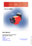
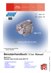
LE-200
User Manual
● Safety notes
● Assembly
● Installation / Commissioning
● Parameter setting
● Causes of Faults and Remedies
● Software/Support CD: 490-01001
- Soft-No.: 490-00416
TR - ELE - BA - GB - 0011 - 02
21.12.2007
Laser Measuring Device LE-200 with SSI - interface
TR-Electronic GmbH
D-78647 Trossingen
Eglishalde 6
Tel.: (0049) 07425/228-0
Fax: (0049) 07425/228-33
E-mail: [email protected]
http://www.tr-electronic.de
Copyright protection
This Manual, including the illustrations contained therein, is subject to copyright
protection. Use of this Manual by third parties in contravention of copyright
regulations is forbidden. Reproduction, translation as well as electronic and
photographic archiving and modification require the written content of the
manufacturer. Offenders will be liable for damages.
Subject to amendments
Any technical changes that serve the purpose of technical progress, reserved.
Document information
Release date/Rev. date:
Document rev. no.:
File name:
Author:
21.12.2007
TR - ELE - BA - GB - 0011 - 02
TR-ELE-BA-GB-0011-02.DOC
MÜJ
Font styles
Italic or bold font styles are used for the title of a document or are used for
highlighting.
Courier font displays text, which is visible on the display or screen and software
menu selections.
″<
> ″ indicates keys on your computer keyboard (such as <RETURN>).
© TR-Electronic GmbH 2007, All Rights Reserved
Page 2 of 37
Printed in the Federal Republic of Germany
TR - ELE - BA - GB - 0011 - 02
21.12.2007
Revision History
Revision History
i
Note
The cover of this document shows the current revision status and the corresponding
date. Since each individual page has its own revision status and date in the footer,
there may be different revision statuses within the document.
Documents that are in the appendix have their own revision history.
Document created:
24.10.2003
Revision
Date
- Revision of the warning label in chapter "Intended purpose"
18.12.2003
- Modification of the Laser Standard DIN EN 60825-1
- Warning bit “Plausibility measured value”
- Additional reflector foils, chap. Accessories
- Max. measuring range 240 m
- Modification of the parameters
21.12.2007
© TR-Electronic GmbH 2007, All Rights Reserved
Printed in the Federal Republic of Germany
21.12.2007
TR - ELE - BA - GB - 0011 - 02
Page 3 of 37
Table of Contents
Table of Contents
Revision History ...............................................................................................................................3
Table of Contents .............................................................................................................................4
1 Safety ..............................................................................................................................................6
1.1 General risk potential.......................................................................................................6
1.2 Safety information............................................................................................................6
1.2.1 Hints on installation..........................................................................................7
1.2.1.1 General interference suppression measures ..................................8
1.3 Intended purpose.............................................................................................................9
1.4 Authorized operators .......................................................................................................11
1.5 Safety measures at the installation site...........................................................................11
2 General Description ......................................................................................................................12
3 Transportation / Storage...............................................................................................................13
4 Assembly instructions ..................................................................................................................14
4.1 Aligning of the laser light spot to the reflector / foil inclination.........................................14
4.2 Parallel operation of laser linear paths ............................................................................16
5 Commissioning / Installation .......................................................................................................17
5.1 Electrical connection........................................................................................................17
5.1.1 Supply voltage .................................................................................................17
5.1.2 SSI interface ....................................................................................................17
5.1.3 Switching input / Switching output ...................................................................18
5.1.4 RS485 - programming interface ......................................................................18
5.1.5 Wiring examples ..............................................................................................19
5.2 SSI interface ....................................................................................................................20
6 Configuration / Parameter setting via TRWinProg.....................................................................22
6.1 Basic parameter ..............................................................................................................22
6.1.1 Count direction.................................................................................................22
6.1.2 Resolution ........................................................................................................22
6.1.3 Measuring-Dynamic.........................................................................................22
6.1.4 Measuring-Output-Time...................................................................................23
6.1.5 Physical Resolution .........................................................................................23
6.2 SSI interface ....................................................................................................................24
6.2.1 Number of data bits .........................................................................................24
6.2.2 Code ................................................................................................................24
6.2.3 Fail-Bit SSI .......................................................................................................24
6.2.4 Output value SSI..............................................................................................25
6.3 Failure-Handling ..............................................................................................................26
6.3.1 Fail Output .......................................................................................................26
6.3.2 Level Fail Output..............................................................................................26
6.3.3 Failure-quit.......................................................................................................26
6.3.4 Output value in case of an error ......................................................................27
6.3.5 Warning bit Temperature from.........................................................................27
6.3.6 Warning bit Intensity under ..............................................................................27
© TR-Electronic GmbH 2007, All Rights Reserved
Page 4 of 37
Printed in the Federal Republic of Germany
TR - ELE - BA - GB - 0011 - 02
21.12.2007
Table of Contents
6.4 Preset ..............................................................................................................................28
6.4.1 Function ext. Input (Switching Input) ...............................................................28
6.4.2 Active Input-Slope............................................................................................28
6.4.3 Input-Active-Time.............................................................................................28
6.4.4 Preset-Value ....................................................................................................29
6.4.5 Preset reset .....................................................................................................29
6.5 Actual values ...................................................................................................................30
6.5.1 Position ............................................................................................................30
6.5.2 Device state .....................................................................................................31
6.5.3 Hardware-Info ..................................................................................................31
6.6 Speed ..............................................................................................................................32
6.6.1 Speed-Values ..................................................................................................32
6.6.2 Dynamic ...........................................................................................................32
6.6.3 Output-Format .................................................................................................32
6.6.4 Sign..................................................................................................................33
7 Causes of Faults and Remedies ..................................................................................................34
8 Maintenance...................................................................................................................................35
8.1 General Maintenance Information ...................................................................................35
8.2 Repair, Maintenance .......................................................................................................35
9 Appendix ........................................................................................................................................36
9.1 Specifications...................................................................................................................36
9.1.1 Electrical ratings ..............................................................................................36
9.1.2 Environmental conditions ................................................................................37
9.2 Accessories .....................................................................................................................37
Pin Assignment.......................................................................................................... No.: 3296
Drawings
Dimensioned drawing ............................................................................ 04-K2200-005
© TR-Electronic GmbH 2007, All Rights Reserved
Printed in the Federal Republic of Germany
21.12.2007
TR - ELE - BA - GB - 0011 - 02
Page 5 of 37
Safety
1 Safety
1.1 General risk potential
The Laser Measuring Device LE-200 SSI cannot be operated independently, but is
installed as part of an overall system usually consisting of several interacting
components. For this reason, the laser measuring device is not equipped directly with
a protective device.
Warning
The corresponding measures must be taken in order to avoid person and
property damages!
However, over a hardware output or over the SSI format different error messages
such as temperature-, intensity- or hardware-errors can be read out. Depending on
setting, for resetting an acknowledgement of the error is to be made. More
information's see chapter "Failure-Handling", page 26. It is therefore essential to
integrate the error messages into your own safety system via the evaluation
software (e.g. a PLC).
All persons responsible for the assembly, start-up and operation of the device must
• be suitably qualified
• adhere strictly to this operating manual.
Your safety and the safety of your equipment depends on this!
1.2 Safety information
This operating manual contains information which must be observed in the interests of
your own personal safety and that of your equipment. The safety hints are
emphasized by a warning triangle and classified according to the degree of danger as
follows:
Warning
means that failure to take the relevant safety precautions can lead to serious damage
to property or injuries.
i
Note
refers to important information and features of the product, plus tips on its application.
© TR-Electronic GmbH 2007, All Rights Reserved
Page 6 of 37
Printed in the Federal Republic of Germany
TR - ELE - BA - GB - 0011 - 02
21.12.2007
Safety
1.2.1 Hints on installation
Since the Laser Measuring Device is normally used as part of a larger system, these
hints are merely intended as a guide for integrating the device safely into its
environment.
Warning
• During the operation of the Laser Measuring Device it isn't allowed to interrupt the
laser beam. If it comes nevertheless to an interruption, at the restart of the
automatic operation mode first the validity (plausibility) of the measured value has
to be checked.
• Precautionary measures must be taken to allow an interrupted program to be
properly resumed following a voltage drop or failure. Dangerous operating
conditions must not be permitted to arise even for short periods. If necessary, an
"EMERGENCY STOP" must be forced.
• EMERGENCY STOP devices according to EN 60204/IEC 204 (VDE 0113) must
remain operational in all operating modes of the programmable controller. The
release of the EMERGENCY STOP devices must not trigger an uncontrolled or
undefined reactivation of the equipment.
• The safety and accident prevention regulations applicable to the specific
application must be observed.
• In the case of permanently installed plants or systems without an all-pole mains
switch and/or fuses, one of these devices must be installed accordingly and the
equipment connected to a PE conductor.
• In the case of 24 V supplies, make sure the extra-low voltage is reliably
disconnected. Only use power supply units manufactured to the standards
IEC 364 - 4 - 41 / HD 384.04.41 (VDE 0100 Part 410).
• Fluctuations or deviations of the supply voltage from the nominal value must not
exceed the tolerance limits stated in the specifications, otherwise operational
failures and dangerous states in the electrical assemblies cannot be ruled out.
• Connecting and signal wires must be installed in such a way as to prevent the
automation functions from being hampered by inductive and capacitive
interference.
• The units of the automation system and their operating elements must be installed
in such a way as to ensure adequate protection against accidental actuation.
• In order to prevent a wire or strand breakage on the signal side from causing
undefined states in the programmable controller, suitable hardware and software
safety precautions must be taken with regard to the I/O interface.
© TR-Electronic GmbH 2007, All Rights Reserved
Printed in the Federal Republic of Germany
21.12.2007
TR - ELE - BA - GB - 0011 - 02
Page 7 of 37
Safety
1.2.1.1 General interference suppression measures
•
Lay the (shielded) connecting cable to the device at a sufficient distance or in a
separate room from any power cables which are subject to interference. Otherwise the
data transmission of the measured value can be interfered.
•
To ensure reliable data transmission, use fully shielded cables and make sure they are
well earthed. For differential data transfer (RS422, RS485 etc.), twisted-pair wires must
be used in addition.
•
Use a minimum cable cross-section of 0.25 mm2 for the SSI-signals data+/- and clock +/-.
•
Use a minimum earthing cable (machine base) cross-section of 10 mm2 in order to
avoid equipotential currents across the shield. Make sure the resistance of the earthing
cable is much lower than that of the shield.
•
Avoid crossing cables where possible. If unavoidable, only cross them at right-angles.
•
Ensure continuous wiring of the shield and a large contact area on special cable screw
glands (mating connector, female connector):
Step A:
1.-2.
Push clamp ring and cable clamp with seal
over cable.
(If required insert sleeve order no.
FC6CX004I00X is helpful)
3.
Strip cable 24mm.
4.
Push shielding back over cable.
Step B:
5.
Strip cores 5mm.
Step C:
6.
Put shielding ring on.
7.
Twist remaining shielding around shielding
ring.
Step D:
8.
Solder wires in contacts.
Step E:
9.
Snap distance ring over insulation body.
10.
Push insulation body into bridge of plug
housing.
11.
Screw clamp ring onto plug housing.
© TR-Electronic GmbH 2007, All Rights Reserved
Page 8 of 37
Printed in the Federal Republic of Germany
TR - ELE - BA - GB - 0011 - 02
21.12.2007
Safety
1.3 Intended purpose
The measuring system is used for recording linear movements and processing the
measured data for a downstream control system with a synchronous-serial
interface (SSI).
Particularly the measuring system is designed for the use of distance measurements
for the detection of the position and positioning of:
!
!
!
!
High-bay storage devices and lifting gears
Crane systems
Side-tracking skates and truck storage vehicles
Transfer machines
Warning
Switch off the voltage supply before carrying out wiring work or opening and
closing electrical connections!
Short-circuits, voltage peaks, etc. can cause operating failures and uncontrolled
operating states, as well as serious personal injuries and damage to property.
Check all electrical connections before switching on the system!
Incorrectly wired connections can cause operating failures, while wrong connections
can lead to serious personal injuries and damage to property.
Mechanical or electrical modifications to the measuring systems are prohibited
for safety reasons!
In particular the following uses are forbidden
operation in areas where interruption of the laser beam, e.g. by covering the
laser lens opening, can lead to equipment damage or injury to personnel
-
in environments, in which strong rain, snow, fog, steams or direct insolations
etc. can influence the laser beam intensity negatively
-
operation in rooms with explosive atmospheres
-
operation for medical purposes
With use-purposes larger 125m measuring length, a special reflector must to be
used! (see chapter "Accessories", page 37)
© TR-Electronic GmbH 2007, All Rights Reserved
Printed in the Federal Republic of Germany
21.12.2007
TR - ELE - BA - GB - 0011 - 02
Page 9 of 37
Safety
Warning
Laser Light
Do not stare into the beam
Laser Class 2
P max = 1 mW, λ = 670 nm
DIN EN 60825-1: 2003-10
Complies with 21 CFR 1040.10 and
1040.11 except for deviations pursuant
to laser notice No. 50, July 2001
• In the case of Class 2 laser devices, the eye is not endangered if the exposure of
the laser radiation is very short (up to 0.25 s) and accidental. For this reason,
devices of this class can be used without additional protective measures, provided
for the application it is not necessary to look into the laser beam deliberately for
longer periods, i.e. 0.25 s, or to look repeatedly into the laser beam itself or the
specular reflected beam.
The existence of the blinking reflex for the protection of the eyes may not be
assumed. Therefore the eyes should be closed consciously, or the head
should be turned away immediately!
• The device must be installed in such a way that the exposure of persons to the
laser beam can only happen accidentally.
• The laser beam may only extend as far as is necessary for the range
measurement. The beam must be limited at the end of the useful range by a
diffusely reflecting target area in such a way as to minimize the danger from direct
or diffuse reflection. For this purpose, you should use the TR-Electronic reflecting
foil supplied with the device.
• The area outside the operating range where the unshielded laser beam falls should
be limited as far as possible and should remain out of bounds, particularly in the
area above and below eye level.
• Observe the legal and local regulations applicable to the operation of laser units.
i
Note
The start-up, operating and programming instructions contained in this manual are
mandatory.
© TR-Electronic GmbH 2007, All Rights Reserved
Page 10 of 37
Printed in the Federal Republic of Germany
TR - ELE - BA - GB - 0011 - 02
21.12.2007
Safety
1.4 Authorized operators
The start-up and operation of this device may only be performed by qualified
personnel. For the purposes of this manual, the term "qualified personnel" refers to
persons who are authorized to operate, earth and label equipment, systems and
power circuits according to recognized safety standards.
1.5 Safety measures at the installation site
Warning
Do not perform any welding work once the device is connected and switched on!
Variations in potential can destroy the device or restrict its operation.
Do not touch plug contacts with your hands!
Static charges may destroy electronic components of the device.
Do not connect unused inputs (see pin assignment)!
Observe the voltage supply range:
Standard device:
18-27 V DC (± 5 %)
Device with heating:
24 V DC (± 5 %)
Clean lens opening of the laser and the reflecting foil regularly!
(see chapter "Maintenance", page 35)
i
Note
Make sure that the environment of the installation site is protected against corrosive
media (acids, etc.)
© TR-Electronic GmbH 2007, All Rights Reserved
Printed in the Federal Republic of Germany
21.12.2007
TR - ELE - BA - GB - 0011 - 02
Page 11 of 37
General Description
2 General Description
The laser measuring devices of the series LE are optical sensors, with which larger
distances can be measured without contact and serviceable for controller. The
measuring system consists of the real measuring device with laser light source,
receiving optics, electronic evaluation and data interface as well as a reflector. The
device sends out a modulated light beam which is reflected by the reflector. From the
phase difference of the sent and received light beam the distance is measured 1000
times per second. Thus the LE is suitable also directly for the position feedback in
controller loops.
According to the requirements the laser distance measuring devices of the series
LE-200 SSI are configured with the PC-programming software "TRWinProg".
Principle
Receiver signal
ϕ
Transmitter signal
ϕ = Phase displacement
Reflecting foil
d = Distance
d = f(ϕ)
Measuring start
0,2m
Measuring end
Display range max. 240m (Special Device)
© TR-Electronic GmbH 2007, All Rights Reserved
Page 12 of 37
Measuring range
125m
Printed in the Federal Republic of Germany
TR - ELE - BA - GB - 0011 - 02
21.12.2007
Transportation / Storage
3 Transportation / Storage
Transport instructions
Do not drop the device or expose it to shocks or vibrations!
Device contains an optical system with glass elements.
Only use the original packaging!
The wrong packaging material can cause damage to the device during transportation.
Storage
Storage temperature : -20 to +75°C
Store in dry conditions.
© TR-Electronic GmbH 2007, All Rights Reserved
Printed in the Federal Republic of Germany
21.12.2007
TR - ELE - BA - GB - 0011 - 02
Page 13 of 37
Assembly instructions
4 Assembly instructions
The adjustment of the laser measuring device in the vertical plain is carried out via
four studs (A) in the mounting plate. The adjustment in the horizontal plane can be
made by four hexagon bolts (B). It has to be taken into account that the screw
diameter is approx. 1-2 mm smaller than the through bore of the mounting plate. Exact
dimensional properties are on the dimensional drawing in the rear part of the
document.
B
A
Figure 1: Mechanical adjustment possibilities
4.1 Aligning of the laser light spot to the reflector / foil inclination
i
The measuring device or reflector is attached to the moving object and the
reflector/sensor to the fixed remote station in such a way that the reflector always
remains within the visual field of the sensor. This can be done using the light spot of
the laser diode, which is still clearly visible on the reflecting foil even at long distance.
When aligning the laser measuring device, the user may need to take measures to
ensure that it can be mechanically adjusted.
The size of the reflecting foil must be such that the light spot cannot be displaced from
the reflector by vibrations. Since with an increasing distance the light spot gets larger
and larger, the edge areas of the foil also have to be avoided.
The device comes with a reflecting foil measuring 20 x 20 [cm], but other sizes can be
ordered on request.
Note
Reflecting foils by other manufacturers should not be used under any circumstances,
as all the information in the "Specifications" chapter refers to the foil already supplied
with the device.
© TR-Electronic GmbH 2007, All Rights Reserved
Page 14 of 37
Printed in the Federal Republic of Germany
TR - ELE - BA - GB - 0011 - 02
21.12.2007
Assembly instructions
Procedure:
• Figure 2: Detection of the surface reflectivity:
At first attaching the reflector foil flatly and drive plant on minimal
distance Laser – Foil.
Centering paper (C) in front of the laser optics so, that the laser beam
can unhinderedly emerge by an approx. 2 cm hole. Now, the interfering
signal (B) should get visible on the paper (C). To the better location of
the interfering signal (B) the reflector foil can be moved also a little.
Here it is valid: angle of incidence = angle of reflection
• Figure 3: Transmitting away the surface reflectivity:
Rotate the reflector foil in the Y- or in the Z-axis so, that the interference
signal (B) always is outside the laser lens. Nevertheless keeping the
inclination of the reflector foil as low as possible to minimize measuring
errors caused by misalignments in the procedure movement. For
example, if the light spot drifts on the reflector foil around, small
differences arise as a result of the oblique position.
Fix reflector foil
(A)
real wanted signal, is always
thrown back 180° independently of the reflector inclination
Figure 2: Detection of the surface reflectivity
(B)
Surface reflectivity
(interference signal)
(C)
Paper with an approx. 2 cm
large hole in the center
Figure 3: Transmitting away the surface reflectivity
© TR-Electronic GmbH 2007, All Rights Reserved
Printed in the Federal Republic of Germany
21.12.2007
TR - ELE - BA - GB - 0011 - 02
Page 15 of 37
Assembly instructions
4.2 Parallel operation of laser linear paths
It has to be taken care in the parallel operation of laser linear paths that a minimum
distance of 1 m is kept. The reflector foil inclination must be made in such a way that
the surface reflectivity (see arrows) points not into the other laser linear path.
The alignment is carried out as described in chapter 4 / 4.1.
Figure 4: Minimum distance in parallel operation
© TR-Electronic GmbH 2007, All Rights Reserved
Page 16 of 37
Printed in the Federal Republic of Germany
TR - ELE - BA - GB - 0011 - 02
21.12.2007
Commissioning / Installation
5 Commissioning / Installation
5.1 Electrical connection
i
Note
At the realization of the electrical connection the references in chapter 1.2.1, starting
from page 7 must be considered.
B
9
1
2
9
7
10 12
3
4
11
4
8
6
7
10 12
3
1
2
8
6
11
5
5
5.1.1 Supply voltage
Pin 11 Standard: 18 – 27 V DC
Device with heating: 24 V DC (±5%)
9
1
2
7
10 12
3
Pin 12 0V, GND
8
4
11
6
5
5.1.2 SSI interface
Pin 1
SSI-Clock –
Pin 2
SSI-Clock +
2
Pin 3
SSI-Data +
3
Pin 4
SSI-Data –
1
8
7
10 12
4
11
6
5
© TR-Electronic GmbH 2007, All Rights Reserved
Printed in the Federal Republic of Germany
21.12.2007
9
TR - ELE - BA - GB - 0011 - 02
Page 17 of 37
Commissioning / Installation
5.1.3 Switching input / Switching output
The programming of the switching input /switching output is carried out directly via the
PC software "TRWinProg".
Functions of the switching input:
- Preset
- Switch off laser diode
- Failure quit
Functions of the switching output:
- Temperature
- Intensity
- Hardware-Fail
- every fail
- Speed-check
- Plausibility measured value
- Switching output position
1
Pin 8
Switching output
2
Pin 9
Switching input
3
9
8
7
10 12
4
11
6
5
5.1.4 RS485 - programming interface
Via the PC software "TRWinProg" and a PC adapter the connection to the laser
measuring device is established. More information's see page 19 or in the TRWinProg
software manual.
1
Pin 5
RS485+
2
Pin 6
RS485–
3
Page 18 of 37
8
7
10 12
4
© TR-Electronic GmbH 2007, All Rights Reserved
9
11
6
5
Printed in the Federal Republic of Germany
TR - ELE - BA - GB - 0011 - 02
21.12.2007
Commissioning / Installation
5.1.5 Wiring examples
* Shield connection, see chapter 1.2.1.1 page 8.
RS485 / SSI - connection with parameter setting via "TRWinProg"
© TR-Electronic GmbH 2007, All Rights Reserved
Printed in the Federal Republic of Germany
21.12.2007
TR - ELE - BA - GB - 0011 - 02
Page 19 of 37
Commissioning / Installation
5.2 SSI interface
In the idle condition the signals Data+ and Clock+ are high. This corresponds the time
before item (1) is following, see chart indicated below.
With the first change of the clock pulse from high to low (1) the internal-devicemonoflop (can be retriggered) is set with the monoflop time tM.
The time tM is set to 20 µs and determines the lowest transfer frequency of
approximately 80 kHz. The upper limit frequency results from the total of all the signal
delay times and is limited additional by the built-in filter circuits to approx.
820 kHz.
With each further falling clock edge the active condition of the monoflop extends by
further 20µs, at last at item (4).
With setting of the monoflop (1), the bit-parallel data on the parallel-serial-converter
will be stored via an internal signal in the input latch of the shift register. This ensures
that the data cannot change during the transmission of a position value.
With the first change of the clock pulse from low to high (2) the most significant bit
(MSB) of the device information will be output to the serial data output. With each
following rising edge of the clock pulse, the next lower significant bit is set on the data
output.
When the clock sequence is finished, the system keeps the data lines at 0V (Low) for
the duration of the mono period, tM (4). With this, the admissible break time tp between
two successive clock sequences is determined and is >20µs.
Caused be the delay time tv (approx. 100ns, without cable), the evaluation electronic
must be read-in the data only at time (3). This corresponds to the second rising clock
edge. For this reason the number of clock pulses corresponds the number of data bits +1.
Typical SSI - transmission sequences
tp
Clock+
Data+
Monoflop Time
SSI transmission format
1
Clock+
Data+
2
3
1
4
T
2
n+1
n
MSB
tM
LSB
High
Low
High
Low
tV
internal
Monoflop, can be retriggered
© TR-Electronic GmbH 2007, All Rights Reserved
Page 20 of 37
High
Low
Printed in the Federal Republic of Germany
TR - ELE - BA - GB - 0011 - 02
21.12.2007
Commissioning / Installation
The maximum cable length depends on the SSI clock frequency and should be
conditioned to the following diagram.
Pay attention, that per meter cable with an additional delay-time of approx. 6ns must
be calculated.
Transmission rate in KHz
1000
800
600
400
200
0
50
0
150
100
250
200
350
450
300
400
550
500
Cable length in m
Cable length [m]
SSI-clock frequency [kHz]
12,5
25
50
100
200
400
500
810
750
570
360
220
120
100
© TR-Electronic GmbH 2007, All Rights Reserved
Printed in the Federal Republic of Germany
21.12.2007
TR - ELE - BA - GB - 0011 - 02
Page 21 of 37
Configuration / Parameter setting via TRWinProg
6 Configuration / Parameter setting via TRWinProg
6.1 Basic parameter
6.1.1 Count direction
The counting direction defines whether increasing or decreasing position values are
output.
Selection
Description
Default
Up
With increasing distance to the laser, values increasing
Down
With increasing distance to the laser, values decreasing
X
6.1.2 Resolution
Definition of the measuring system resolution.
Selection
Default
10 mm
1 mm
X
1/10 mm
1/100 mm
1 Inch
1/10 Inch
1/8 mm
Free resolution (in 1/100 mm), valid values are 1 - 65535
For example 1 mm corresponds the input value of 100.
That means the laser outputs 1 step/mm.
100
6.1.3 Measuring-Dynamic
Measuring-dynamic is an parameter, who characterize mathematic calculation of the
measure-value. With high measuring-dynamic there is no mathematic calculation on
the measure-value, but the noise of the measure-value is larger, in case of small
measuring-dynamic the noise is lower, but there exist a small time-delay for the
measure-value.
Selection
Default
slow
mid
X
high
© TR-Electronic GmbH 2007, All Rights Reserved
Page 22 of 37
Printed in the Federal Republic of Germany
TR - ELE - BA - GB - 0011 - 02
21.12.2007
Configuration / Parameter setting via TRWinProg
6.1.4 Measuring-Output-Time
The Measuring-Output-Time defines the time for calculating the measuring value.
Selection
Default
1 ms
X
2 ms
3 ms
4 ms
5 ms
6 ms
7 ms
8 ms
9 ms
10 ms
15 ms
20 ms
25 ms
30 ms
50 ms
100 ms
200 ms
500 ms
6.1.5 Physical Resolution
The physical resolution of the measuring system is the smallest possible resolution,
with which the measured value can be produced.
Selection
Default
0.76 mm
X
0.1 mm
© TR-Electronic GmbH 2007, All Rights Reserved
Printed in the Federal Republic of Germany
21.12.2007
TR - ELE - BA - GB - 0011 - 02
Page 23 of 37
Configuration / Parameter setting via TRWinProg
6.2 SSI interface
6.2.1 Number of data bits
The number of data bits defines the max. number of data bits which can be
transferred on the SSI interface. A possibly defined error bit is not contained.
Selection
Description
12 bit
Number of SSI data bits = 12
...
...
24 bit
Number of SSI data bits = 24
25 bit
Number of SSI data bits = 25
26 bit
Number of SSI data bits = 26
27 bit
Number of SSI data bits = 27
28 bit
Number of SSI data bits = 28
29 bit
Number of SSI data bits = 29
30 bit
Number of SSI data bits = 30
31 bit
Number of SSI data bits = 31
32 bit
Number of SSI data bits = 32
Default
X
6.2.2 Code
Defines the SSI output code.
Selection
Description
Gray
SSI output code = Gray
Binary
SSI output code = Binary
Default
X
6.2.3 Fail-Bit SSI
The SSI error bit is an additional bit in the SSI protocol and is attached after the
"LSB-bit". Definition of errors see "Device state", page 31.
Selection
Default
disabled
X
Temperature
Intensity
Hardware
Every Failure
Plausibility measured value
© TR-Electronic GmbH 2007, All Rights Reserved
Page 24 of 37
Printed in the Federal Republic of Germany
TR - ELE - BA - GB - 0011 - 02
21.12.2007
Configuration / Parameter setting via TRWinProg
6.2.4 Output value SSI
The SSI output value specifies the value, which is output on the SSI interface.
Selection
Description
Position
Output of the Laser position
Intensity
Output of the Laser intensity value
Speed
Output of the Laser actual speed
Position + Speed
21 bit position data, 11 bit speed. The number of
data bits must be set to 32. Max. possible
resolution = 0.1 mm.
X
© TR-Electronic GmbH 2007, All Rights Reserved
Printed in the Federal Republic of Germany
21.12.2007
Default
TR - ELE - BA - GB - 0011 - 02
Page 25 of 37
Configuration / Parameter setting via TRWinProg
6.3 Failure-Handling
6.3.1 Fail Output
Determines the function of the error output (external switching output). Definition of
errors see "Device state", page 31.
Selection
Default
disabled
X
Temperature
Intensity
Hardware-Fail
every fail
Speed-check
Plausibility measured value
Switching output position
6.3.2 Level Fail Output
Specifies the active output level of the selected error, if the error occurs.
Selection
Description
active HIGH
Error active, Switching Output = HIGH
active LOW
Error active, Switching Output = LOW
Default
X
6.3.3 Failure-quit
Determines, whether occurring error reports should be cleared automatically after
eliminating the trouble.
Selection
Description
automatic
An occurring error report is cleared automatically
after remedying of the error.
not automatic
An occurring error report can be cleared only via
the external switching input (see "Function ext.
Input (Switching Input)", page 28).
© TR-Electronic GmbH 2007, All Rights Reserved
Page 26 of 37
Default
X
Printed in the Federal Republic of Germany
TR - ELE - BA - GB - 0011 - 02
21.12.2007
Configuration / Parameter setting via TRWinProg
6.3.4 Output value in case of an error
Determines, which data value is to be transmitted in the case of an error. The data
value is output, if the laser can output no more measurement. This is given e.g., if a
beam interruption is present.
Selection
Description
all 0
The position is set to "0"
all 1
All 24 bits are set to '1' (0xFFFFFF or -1)
last valid value
Output of the last valid position
Default
X
6.3.5 Warning bit Temperature from
Determines, starting from which temperature the warning bit or switching output will be
set.
Selection
Description
47
Message, if device temperature ≥ 47 °C
48
Message, if device temperature ≥ 48 °C
49
Message, if device temperature ≥ 49 °C
50
Message, if device temperature ≥ 50 °C
Default
X
6.3.6 Warning bit Intensity under
Determines, starting from which intensity value of the laser beam the warning bit or
switching output will be set.
Input
1 – 100 [%]
Description
Message, if intensity value < Input value
12 %
© TR-Electronic GmbH 2007, All Rights Reserved
Printed in the Federal Republic of Germany
21.12.2007
Default
TR - ELE - BA - GB - 0011 - 02
Page 27 of 37
Configuration / Parameter setting via TRWinProg
6.4 Preset
6.4.1 Function ext. Input (Switching Input)
Determines, whether the switching input is to be used as
Preset input
Switch-off Laser-Diode (LD) or
Failure reset - input
With connection of the switching input as Preset-input the laser is adjusted on the
predefined position value in chapter "Preset-Value", page 29. With connection the
switching input as LD-input the laser diode is switched off for the extension of the life
time. If in the PC-program "TRWinProg" in the basic parameters the switching-off of
the laser diode is carried out automatically, the LD-switching input does not have a
function.
Selection
Description
Default
disabled
Function switched off, following parameters
without meaning.
Preset function
External switching input is determined as Preset
input.
LD switching input
External switching input is used for switching-off of
the laser diode.
Error
acknowledgement
X
External switching input is used as error
acknowledgement.
6.4.2 Active Input-Slope
It determines whether the function of the switching input is activated with an rising or
falling edge at the switching input.
Selection
Description
Low->High
Function release with rising edge
High->Low
Function release with falling edge
Default
X
6.4.3 Input-Active-Time
It determines the response time of the switching edge of the switching input up to the
actual execution. This parameter is used for the interference suppression of the signal
at the switching input.
Selection
Description
100 ms
Response time = 100 ms
200 ms
Response time = 200 ms
500 ms
Response time = 500 ms
1000 ms
Response time = 1000 ms
© TR-Electronic GmbH 2007, All Rights Reserved
Page 28 of 37
Default
X
Printed in the Federal Republic of Germany
TR - ELE - BA - GB - 0011 - 02
21.12.2007
Configuration / Parameter setting via TRWinProg
6.4.4 Preset-Value
Definition of the position value to which the laser is adjusted, when the preset function
is executed (see "Function ext. Input (Switching Input)", page 28).
The preset value must be programmed in the range from 0 ... measuring length (see
"Range", chapter "Specifications", page 36). Default value is "0".
6.4.5 Preset reset
Via this parameter, the calculated zero-point is deleted (difference of the desired
preset value to the physical laser position). After deletion of the zero-point correction
the laser outputs his "real" physical position. With the adjusting = "Yes" no
Preset/Adjustment can be executed.
Selection
Description
Default
Yes
Clear Preset
X
No
No clearing
© TR-Electronic GmbH 2007, All Rights Reserved
Printed in the Federal Republic of Germany
21.12.2007
TR - ELE - BA - GB - 0011 - 02
Page 29 of 37
Configuration / Parameter setting via TRWinProg
6.5 Actual values
In this tab all required operation parameters will be displayed:
-
Position, with the resolution adjusted in the basic parameters
-
Intensity [%]
-
Device-Temperature [°C]
-
Speed, with the output format adjusted in the speed parameters
-
Device state
-
Hardware-Info
6.5.1 Position
By writing of a value into the field position the laser can be adjusted on the desired
position value. The execution is carried out with transmission of the values to the laser
measuring device.
The value must be programmed in the range from 0 ... measuring length (see
"Range", chapter "Specifications", page 36).
© TR-Electronic GmbH 2007, All Rights Reserved
Page 30 of 37
Printed in the Federal Republic of Germany
TR - ELE - BA - GB - 0011 - 02
21.12.2007
Configuration / Parameter setting via TRWinProg
6.5.2 Device state
The device state displays the actual state of the device and is coded bitwise:
Error-Code
Description
Intensity
Bit 0
The bit is set, if an intensity value of smaller 8% is
present, or the laser beam is interrupted and leads to the
error value output (see chapter "6.3.4", page 26).
Temperature
Bit 1
The bit is set, if the device temperature is outside of the
range from 0 - 50 °C. A low range deviation has still no
influence on the measurement and is therefore to be
regarded as a warning.
Hardware
Bit 2
The bit is set, if an internal hardware error were noticed
and leads to the error value output
(see chapter "6.3.4", page 26).
Laser diode switched off
Bit 3
The bit is set, if the laser diode was switched off over the
switching input. Serves only for information purposes.
Intensity warning
Bit 4
The bit is set, if an intensity value of smaller 12% were
determined and means that the measuring system optics,
or the reflecting foil is to be cleaned. However, the device
operates error-freely furthermore.
Overspeed warning
Bit 5
The bit is set if the speed, adjusted in the PC program
TRWinProg, is exceeded. About the default setting the
speed-check is switched off.
Warning bit Plausibility
Bit 6
The bit is set if the plausibility of the measured value
cannot be guaranteed. E.g. this is the case at a position
jump if a second reflection foil is held into the laser beam.
6.5.3 Hardware-Info
The Hardware-Info refers to bit two "Hardware Error" in the Device state and specifies
the hardware error in detail.
Error-Code
Bit 0, Failure Fieldbus-Chip
Bit 1, undefined Measuring length
Bit 2, Failure Temperature-Sensor
Bit 3, Failure ext. Flash
© TR-Electronic GmbH 2007, All Rights Reserved
Printed in the Federal Republic of Germany
21.12.2007
TR - ELE - BA - GB - 0011 - 02
Page 31 of 37
Configuration / Parameter setting via TRWinProg
6.6 Speed
6.6.1 Speed-Values
Adjusting of the velocity level. If the adjusted velocity level is exceeded, this is
signalized with the setting of the switching output. For this, about the function of the
switching output the output must be defined as "Speed-check" (see "Fail Output",
page 26).
Selection
Description
0
Function disabled
free input: 1 - 200
Speed in 0,1 m/s
Default
X
6.6.2 Dynamic
Time constant for calculating the speed.
Selection
Description
Default
Auto-Dynamic Dynamic ranging depending from the speed level.
Range 1
lower delay, higher noise
Range 2
middle delay, middle noise
Range 3
higher delay, lower noise
X
6.6.3 Output-Format
Definition of the output format for the speed which is displayed in the tab Actual
values.
Selection
Description
1 mm / sec
Output of the speed in 1 mm/s
10 mm / sec
Output of the speed in 10 mm/s
© TR-Electronic GmbH 2007, All Rights Reserved
Page 32 of 37
Default
X
Printed in the Federal Republic of Germany
TR - ELE - BA - GB - 0011 - 02
21.12.2007
Configuration / Parameter setting via TRWinProg
6.6.4 Sign
Definition if the speed, which is displayed in the tab Actual value, is output with
sign or without sign.
Selection
Description
no sign, always positive
Output without sign
direction depending sign
Output as value with sign
X
© TR-Electronic GmbH 2007, All Rights Reserved
Printed in the Federal Republic of Germany
21.12.2007
Default
TR - ELE - BA - GB - 0011 - 02
Page 33 of 37
Causes of Faults and Remedies
7 Causes of Faults and Remedies
The error causes are determined in chapter "Device state", page 31. Depending on
setting the error messages must be acknowledged for resetting the error, see chapter
"Failure-quit", page 26.
Error
Cause
Remedy
The device checks
the intensity of the
Bit 0
received laser signal
Intensity error
continuously, it was
detected a belowminimum intensity.
1.
2.
3.
Clean measuring system optics
Clean reflecting foil
Rule out an interruption of the laser beam
If the possibility of soiling or interruption of the laser signal
can be ruled out, the device must be replaced.
The temperature has
exceeded or fallen
Bit 1
Device temperature
short of the range of
0 - 50°C at the
Appropriate measures must be taken to prevent the device
from overheating or undercooling.
housing of the device
The device has
Bit 2
Hardware error
detected an internal
If the error occurs repeated, the device must be replaced.
hardware error.
The bit is set, if the
Bit 3
laser
Laser diode
switched off over the Serves only for information purposes.
bus, or the switching
switched off
diode
was
input.
Bit 4
Intensity warning
Bit 5
Speed-check warning
Bit 6
Plausibility warning
The
device
deter-
mined an intensity of
< 12%.
This message is only a warning and means that the
measuring system optics, or the reflecting foil is to be
cleaned.
the
device
operates
error-freely
The
speed
level This message is a warning and means that possibly
adjusted over the PC corresponding measures must be taken, so that no system
program TRWinProg
components will be damaged.
was exceeded.
The plausibility of the This message is a warning and means that possibly
measured
value corresponding measures must be taken, so that no system
couldn't be guarancomponents will be damaged.
teed any more.
© TR-Electronic GmbH 2007, All Rights Reserved
Page 34 of 37
However,
furthermore.
Printed in the Federal Republic of Germany
TR - ELE - BA - GB - 0011 - 02
21.12.2007
Maintenance
8 Maintenance
8.1 General Maintenance Information
The Laser Measuring Device does not, in general, require maintenance by the
operator.
i
Note
If the lens opening of the laser or the reflecting foil become dirty, clean with a soft
cloth.
Do not use an aggressive cleaning material such as thinner or acetone !
8.2 Repair, Maintenance
Repairs to the devices must only be carried out by the manufacturer.
Contact your TR-Electronic GmbH distributor or service organization should repairs be
required. The addresses are listed on the last page of this description.
© TR-Electronic GmbH 2007, All Rights Reserved
Printed in the Federal Republic of Germany
21.12.2007
TR - ELE - BA - GB - 0011 - 02
Page 35 of 37
Appendix
9 Appendix
9.1 Specifications
i
Note
The electric characteristics have validity, only after an operating time of approximate
30 minutes.
9.1.1 Electrical ratings
Measuring principle: ................................. Phase delay time measurement
Range (measurem. on reflecting foil): .... 0,2 – 125 m standard,
170m, 195m, 240m (special devices)
* Resolution: .............................................. selectable, physical resolution 0,7 mm
Linearization
up to 12m (standard):................ absolute linearity error ±3 mm
complete measuring length:...... absolute linearity error ±5 mm
Operating voltage
Standard device: ....................... 18-27 V DC (± 5%)
Device with heating: .................. 24 V DC (± 5%)
Power consumption (no-load):................ < 6 watts
Power consumption with heating: .......... < 60 watts
Opto-transmitter:.......................................
Wavelength λ: ...........................
Max. laser power:......................
Laser protection class: ..............
Lifetime:.....................................
Laser diode (red light)
670 nm
P ≤ 1 mW
2 according to DIN EN 60 825-1: 2003-10
50 000 h
Measured value output / refresh cycle: .. 1000 values / s
Integration time: ........................................ 1 ms
Reproducibility:......................................... ± 2 mm
Programming via RS485:.......................... PC IBM compatible (TRWinProg)
SSI Interface: .............................................
Clock input: ...............................
Clock frequency: .......................
* Output code: ...........................
* SSI output value: ....................
Cable length: .............................
Data output:...............................
* Number of data bits: ...............
Clock/Data, twisted pair cables and shielded
Optocoupler
80 kHz - 820 kHz
Binary, Gray
Position, Intensity, Speed
Depending on cable cross section, shielding, clock frequency etc.
RS422 (4-wire)
12-26, with error bit transmission (Temperature, Intensity, Hardware)
* Switching input / Switching output
Levels switching input: .............. 1-level > +8V, 0-level < +2V, up to ±35V, 5 kOhm
Levels switching output:............ 1-level > US-2V, 0-level < 1 V, up to 100mA
* programmable parameter
© TR-Electronic GmbH 2007, All Rights Reserved
Page 36 of 37
Printed in the Federal Republic of Germany
TR - ELE - BA - GB - 0011 - 02
21.12.2007
Appendix
9.1.2 Environmental conditions
EMC: ............................................................................ EN 61000-4-2 (IEC-801-2) /
EN 61000-4-4 (IEC-801-4)
Operating temperature range: .................................. 0-50°C
Device with heating: ................................... -30 to +50°C
Thermal drift: .............................................................. 1 ppm / °C, related to the max. measuring
length of 125 m, 170 m, 195 m or 240 m
Storage temperature range:...................................... -20 to +75°C
Relative air humidity:................................................. 98 % (no moisture condensation)
* Degree of protection: .............................................. IP 65 (DIN 40 050)
Vibration ( 50-2000 Hz Sinusoidal ) DIN IEC 68-2-6:..... ≤ 50 m/s2 (5g)
Shock (11ms) DIN IEC 68-2-27:................................. ≤ 300 m/s2 (30g)
* Valid for the device with screwed-on mating connector and screwed-together cable gland.
9.2 Accessories
Article-No.:
Description
490-00105
TR-PT-15/2: switch cabinet module for PC adapter connection
490-00310
Device: PC adapter (RS485 <--> USB)
490-01001
Soft-No.: 490-00416
"TRWinProg" PC-software with user manual German and English
Reflecting foils for measurements up to 125m
49-500-020
200 x 200 mm, package contents
49-500-038
200 x 300 mm
49-500-031
749 x 914 mm
Other sizes upon request.
In addition, the foils can be sticked-on side-by-side up to the desired size.
Fresnel Reflecting foils for measurements > 125m
49-500-032
554 x 480 mm, package contents
49-500-034
554 x 480 mm, predrilled
49-500-036
720 x 693 mm
49-500-037
1108 x 960 mm
49-500-039
200 x 200 mm, for measurements approx. up to 130m
© TR-Electronic GmbH 2007, All Rights Reserved
Printed in the Federal Republic of Germany
21.12.2007
TR - ELE - BA - GB - 0011 - 02
Page 37 of 37