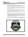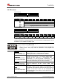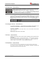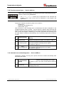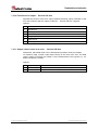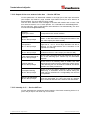
1
LE-200 • Software/Support DVD: 490-01001 - Soft-Nr.: 490-00407 • Additional safety instructions • Installation • Commissioning • Configuration / Parameterization • Troubleshooting / Diagnostic options TR - ELE - BA - GB - 0009 - 08 Laser Measuring Device LE-200 with CAN DeviceNet - interface 18/03/2013 User Manual TR-Electronic GmbH D-78647 Trossingen Eglishalde 6 Tel.: (0049) 07425/228-0 Fax: (0049) 07425/228-33 E-mail: [email protected] http://www.tr-electronic.de Copyright protection This Manual, including the illustrations contained therein, is subject to copyright protection. Use of this Manual by third parties in contravention of copyright regulations is forbidden. Reproduction, translation as well as electronic and photographic archiving and modification require the written content of the manufacturer. Offenders will be liable for damages. Subject to amendments Any technical changes that serve the purpose of technical progress, reserved. Document information Release date/Rev. date: Document rev. no.: File name: Author: 18/03/2013 TR - ELE - BA - GB - 0009 - 08 TR-ELE-BA-GB-0009-08.DOC MÜJ Font styles Italic or bold font styles are used for the title of a document or are used for highlighting. Courier font displays text, which is visible on the display or screen and software menu selections. < > indicates keys on your computer keyboard (such as <RETURN>). Trademarks DeviceNet is a registered trademark of ODVA (Open DeviceNet Vendor Association) TR-Electronic GmbH 2007, All Rights Reserved Page 2 of 28 Printed in the Federal Republic of Germany TR - ELE - BA - GB - 0009 - 08 18/03/2013 Contents Contents Contents ............................................................................................................................................ 3 Revision index .................................................................................................................................. 5 1 General information ...................................................................................................................... 6 1.1 Applicability ...................................................................................................................... 6 2 Additional safety instructions ...................................................................................................... 7 2.1 Definition of symbols and instructions ............................................................................. 7 2.2 Additional instructions for intended use........................................................................... 7 2.3 Organizational measures................................................................................................. 8 3 Technical data................................................................................................................................ 9 3.1 Electrical characteristics .................................................................................................. 9 4 CAN DeviceNet information ........................................................................................................ 10 5 Installation / Preparation for start-up .......................................................................................... 12 5.1 Electrical connection........................................................................................................ 12 5.1.1 Supply voltage ................................................................................................. 12 5.1.2 CAN DeviceNet................................................................................................ 12 5.1.2.1 Bus termination ................................................................................ 13 5.1.2.2 Identifier (MAC-ID) ........................................................................... 13 5.1.2.3 Baud rate ......................................................................................... 13 5.1.2.4 Length of the bus line....................................................................... 13 5.1.3 Switching input / Switching output ................................................................... 14 5.1.4 RS485 - programming interface ...................................................................... 14 5.1.5 General interference suppression measures .................................................. 15 5.1.6 Wiring examples .............................................................................................. 16 6 Commissioning.............................................................................................................................. 17 6.1 CAN DeviceNet interface................................................................................................. 17 6.2 Bus status ........................................................................................................................ 17 6.3 EDS-file ............................................................................................................................ 18 6.4 Messages ........................................................................................................................ 18 6.5 Classes ............................................................................................................................ 18 6.6 I/O Instance ..................................................................................................................... 19 TR-Electronic GmbH 2007, All Rights Reserved Printed in the Federal Republic of Germany 18/03/2013 TR - ELE - BA - GB - 0009 - 08 Page 3 of 28 Contents 7 Parameterization and configuration ............................................................................................ 20 7.1 Configuration Assembly Data Attribute Format ............................................................... 20 7.2 Parameter Object Instances ............................................................................................ 21 7.3 Parameters / Value Ranges ............................................................................................ 21 7.3.1 Direction of Counting - Service 001 hex ........................................................ 21 7.3.2 Clear Preset - Service 002 hex...................................................................... 22 7.3.3 Scaling in 1/100 mm - Service 003 hex ......................................................... 22 7.3.4 Preset - Service 005 hex ............................................................................... 22 7.3.5 Data-Check - Service 006 hex....................................................................... 22 7.3.6 Adjustment - Service 007 hex ........................................................................ 23 7.3.7 Resolution - Service 009 hex ......................................................................... 23 7.3.8 Function external input - Service 00A hex ..................................................... 24 7.3.9 Automatic error acknowledgement - Service 00B hex .................................... 24 7.3.10 Function error output - Service 00C hex ..................................................... 25 7.3.11 Output value in case of an error - Service 00D hex .................................... 25 7.3.12 Output of the error status via the bus - Service 00E hex............................. 26 7.3.13 Intensity in % - Service 00F hex .................................................................. 26 8 Causes of faults and remedies .................................................................................................... 27 9 Appendix ........................................................................................................................................ 28 9.1 Accessories ..................................................................................................................... 28 Pin Assignment ..........................................................................................TR-ELE-TI-GB-0009 Drawings Dimensioned drawing ...................................................................04-K2200-002 TR-Electronic GmbH 2007, All Rights Reserved Page 4 of 28 Printed in the Federal Republic of Germany TR - ELE - BA - GB - 0009 - 08 18/03/2013 Revision index Revision index Revision Date Index 07/22/03 00 0918/03 01 10/09/03 02 12/18/03 03 06/01/07 04 Max. measuring range 240 m 12/18/07 05 Implementation of new reflectors; Physical resolution = 0,1mm 02/02/09 06 Shield connection via cable screw glands removed 01/12/10 07 General changes; Modification of the warnings; Mounting removed 09/11/12 08 First release Expansion of the function for the error output, service 00C Speed-check, configurable via TRWinProg New parameter, service 00F "Intensity in %" Revision of the laser warning label. ● Revision of the shielding concept ● General technical modifications ● Layout modifications TR-Electronic GmbH 2007, All Rights Reserved Printed in the Federal Republic of Germany 18/03/2013 TR - ELE - BA - GB - 0009 - 08 Page 5 of 28 General information 1 General information This interface-specific User Manual includes the following topics: Safety instructions in additional to the basic safety instructions defined in the Assembly Instructions Electrical characteristics Installation Commissioning Configuration and parameterization Troubleshooting and diagnostic options As the documentation is arranged in a modular structure, this User Manual is supplementary to other documentation, such as product datasheets, dimensional drawings, leaflets and the assembly instructions etc. The User Manual may be included in the customer's specific delivery package or it may be requested separately. 1.1 Applicability This User Manual applies exclusively to the following measuring systems with DeviceNet interface: LE-200 The products are labelled with affixed nameplates and are components of a system. The following documentation therefore also applies: the operator's operating instructions specific to the system, this User Manual, and the assembly instructions TR-ELE-BA-DGB-0018, which is enclosed when the device is delivered TR-Electronic GmbH 2007, All Rights Reserved Page 6 of 28 Printed in the Federal Republic of Germany TR - ELE - BA - GB - 0009 - 08 18/03/2013 Additional safety instructions 2 Additional safety instructions 2.1 Definition of symbols and instructions means that death or serious injury can occur if the required precautions are not met. means that minor injuries can occur if the required precautions are not met. means that damage to property can occur if the required precautions are not met. indicates important information or features and application tips for the product used. 2.2 Additional instructions for intended use The measurement system is designed for operation with CAN DeviceNet networks according to the International Standard ISO/DIS 11898 and 11519-1 up to max. 500 kbit/s. The technical g uidelines for the structure of the CAN DeviceNet network from the CAN User Organization ODVA are always to be observed in order to ensure safe operation. Intended use also includes: observing all instructions in this User Manual, observing the assembly instructions. The "Basic safety instructions" in particular must be read and understood prior to commencing work. TR-Electronic GmbH 2007, All Rights Reserved Printed in the Federal Republic of Germany 18/03/2013 TR - ELE - BA - GB - 0009 - 08 Page 7 of 28 Additional safety instructions 2.3 Organizational measures This User Manual must always kept accessible at the site of operation of the measurement system. Prior to commencing work, personnel working with the measurement system must have read and understood - the assembly instructions, in particular the chapter "Basic safety instructions", - and this User Manual, in particular the chapter "Additional safety instructions". This particularly applies for personnel who are only deployed occasionally, e.g. at the parameterization of the measurement system. TR-Electronic GmbH 2007, All Rights Reserved Page 8 of 28 Printed in the Federal Republic of Germany TR - ELE - BA - GB - 0009 - 08 18/03/2013 Technical data 3 Technical data The characteristics have validity, only after an operating time of approximate 30 minutes. 3.1 Electrical characteristics Supply voltage, standard .................................18 - 27 V DC (± 5 %) with heating, optional ...............................24 V DC (± 5 %) Current consumption (no-load).......................< 350 mA with heating, optional ...............................< 2.5 A Measuring principle .........................................Phase delay time measurement Measuring range (on reflecting foil) ...............0.2 – 125 m standard, 170 m, 195 m, 240 m (special devices) * Resolution ......................................................selectable, physical resolution 0.1 mm Linearization up to 12 m (standard) ..............................absolute linearity error ± 3 mm complete measuring length .....................absolute linearity error ± 5 mm Reproducibility .................................................± 2 mm Opto-transmitter ...............................................Laser diode (red light) Wavelength ..........................................670 nm Max. laser power .....................................Pmax ≤ 1 mW Laser protection class .............................2 according to DIN EN 60 825-1: 2003-10 Lifetime, 25°C: .........................................50 000 h Measured value output / refresh cycle ...........1000 values / s Integration time ................................................1 ms Programming via RS485 ..................................WINDOWS® compatible (TRWinProg) / CAN DeviceNet CAN DeviceNet Interface .................................CAN-Fieldbus-Interface (opto-isolated) CAN-BUS-Driver (ISO/DIS 11898) Baud rate (adjustable) .............................125 kbaud, line length up to 500 250 kbaud, line length up to 250 m 500 kbaud, line length up to 100 m Output code .............................................Binary Special features.......................................Configuration of the following parameters via the CAN-Bus: Direction of Counting, Clear Preset, Scaling, Preset, Adjustment, Resolution, Function ext. input, Automatic error acknowledgement, Function error output, Output value in case of an error, Output of the error status via the bus * Switching input/output Levels switching input .............................1 level > +8 V, 0 level < +2 V, up to ± 35 V, 5 kOhm Levels switching output ...........................1 level > US-2 V, 0 level < 1 V, up to 100 mA EMC Immunity to disturbance ..........................DIN EN 61000-6-2: 2006 Transient emissions ................................DIN EN 61000-6-3: 2007 * programmable parameter TR-Electronic GmbH 2007, All Rights Reserved Printed in the Federal Republic of Germany 18/03/2013 TR - ELE - BA - GB - 0009 - 08 Page 9 of 28 CAN DeviceNet information 4 CAN DeviceNet information DeviceNet was developed by Rockwell Automation and the ODVA as an open field bus standard, based on the CAN protocol and is standardized in the European standard EN 50325. Specification and maintenance of the DeviceNet standard is regulated by the ODVA. DeviceNet, along with ControlNet and EtherNet/IP, belongs to the family of CIP-based networks. The CIP (Common Industrial Protocol) forms a common application layer for these 3 industrial networks. DeviceNet, ControlNet and Ethernet/IP are therefore well matched to one another and present the user with a graduated communication system for the physical layer (Ethernet/IP), cell layer (ControlNet) and field layer (DeviceNet). DeviceNet is an object-oriented bus system and works according to the producer/consumer model. DeviceNet Protocol The DeviceNet protocol is an object-oriented protocol. It is typically used for networking sensors and actuators with the superordinate automation devices (PLC, IPC). DeviceNet Data Link Layer Layer 2 (Data Link Layer) is based on the Controller Area Network (CAN), which was originally designed for use in motor vehicles. DeviceNet Network and Data Transport Layer The link is set up with the Group 2 Unconnected Port. Selected CAN identifiers are used for the link set-up. A link, once set up, can be used for transmitting explicit messages or for setting up additional I/O links. As soon as an I/O link has been set up, I/O data can be exchanged between the DeviceNet users. The 11 bit identifier is used exclusively for coding I/O data. The 8-byte wide CAN data field is fully available for user data. DeviceNet Application Layer – CIP Protocol The CIP (Common Industrial Protocol) forms the application layer for DeviceNet. The CIP defines the exchange of I/O data in realtime via I/O messages (I/O messaging or implicit messaging), as well as the exchange of data required for configuration, diagnosis and management via explicit messages (explicit messaging). The communication between two devices always takes place according to a connection-oriented communication model, either via a point-to-point or a multicast-V1 connection. This allows both master/slave and multi-master systems to be realized. Data are known as objects and are logged in the object directory of each device. TR-Electronic GmbH 2007, All Rights Reserved Page 10 of 28 Printed in the Federal Republic of Germany TR - ELE - BA - GB - 0009 - 08 18/03/2013 CAN DeviceNet information Predefined Master-Slave Connection Set The so-called "Predefined Master/Slave Connection Set" is used for the DeviceNet measuring system. This subset of the DeviceNet protocol simplifies the transmission of I/O data between an automation system (PLC) and the decentralized peripheral devices (slaves): Only "Group2 Messages" are supported, with the exception of "Group1 Message for Slave I/O Poll Response". DeviceNet Device Profiles Beyond the specification of the pure communication functions, DeviceNet also includes the definition of device profiles. These profiles define the respective device types for minimally available objects and communication functions. The device type number 08hex was defined for the DeviceNet measuring system. Vendor ID The vendor IDs (manufacturer’s identifiers) are assigned and administrated by the ODVA. The TR-Electronic vendor ID for DeviceNet™ is "134" (dec). You can obtain further information on DeviceNet from the Open DeviceNet Vendor Association (ODVA) or the following Internet addresses: http://www.odva.org e-mail: mailto:[email protected] TR-Electronic GmbH 2007, All Rights Reserved Printed in the Federal Republic of Germany 18/03/2013 TR - ELE - BA - GB - 0009 - 08 Page 11 of 28 Installation / Preparation for start-up 5 Installation / Preparation for start-up 5.1 Electrical connection In order to be able to carry out the connection, the connection cap must be removed from the laser first. For this the screws (A) are loosened and the cap (B) is removed away from the laser. ERR OK RUN B A 1 A 20 X1 DIP-Switch ON OFF 2 0 2 7 5.1.1 Supply voltage Pin 7 0V, GND Pin 8 Standard: 18 – 27 V DC Device with heating: 24 V DC (5%) 1 2 3 4 5 6 7 8 9 10 11 121314 1516171819 20 5.1.2 CAN DeviceNet Pin 15 GNDI (reference potential CAN_L / CAN_H) Pin 16 Shield (internal RC-element onto case) Pin 17 CAN_H 1 2 3 4 5 6 7 8 9 10 11 121314 1516171819 20 Pin 18 CAN_H Pin 19 CAN_L Pin 20 CAN_L TR-Electronic GmbH 2007, All Rights Reserved Page 12 of 28 Printed in the Federal Republic of Germany TR - ELE - BA - GB - 0009 - 08 18/03/2013 Installation / Preparation for start-up 5.1.2.1 Bus termination For the communication a defined no-signal level must be guaranteed on the CAN bus. To this both line ends have to be terminated with terminating resistors. In the laser measuring device is not provided an add-on connection of the terminating resistor. Therefore, if the laser measuring device is the last slave in the CAN bus line, the termination must be made manually with a terminating resistor of 121 ohms between the CAN_H and CAN_L lines. 5.1.2.2 Identifier (MAC-ID) 1 2 3 4 5 6 7 8 9 10 11 12 13 14 15 16 17 18 19 20 The identifier (laser address) 0 – 63 is adjusted via the DIL-switches 1-6: DIL-1 = ID 20, DIL-6 = ID 25 Note: The adjusted address may be assigned only once in the CAN DeviceNet bus. 1 2 DIP-Switch ON 0 2 7 OFF 5.1.2.3 Baud rate The baud rate is adjusted via the DILswitches 7-8: 1 2 3 4 5 6 7 8 9 10 11 12 13 14 15 16 17 18 19 20 DIP-7 DIP-8 Baud rate OFF OFF 125 kbps ON OFF 250 kbps OFF ON 500 kbps 1 2 DIP-Switch ON 0 2 7 OFF 5.1.2.4 Length of the bus line The max. bus line length is dependent on the adjusted baud rate: Baud rate [kbps] 125 250 500 Line length [m] approx. 500 approx. 250 approx. 100 TR-Electronic GmbH 2007, All Rights Reserved Printed in the Federal Republic of Germany 18/03/2013 TR - ELE - BA - GB - 0009 - 08 Page 13 of 28 Installation / Preparation for start-up 5.1.3 Switching input / Switching output Risk of injury and damage to property by an actual value jump when the preset function is performed! The preset function should only be performed at rest, otherwise the resulting actual value jump must be permitted in the program and application! The programming of the switching input / switching output is carried out either directly via the bus, or via the PC software "TRWinProg". Functions of the switching input: - Preset - Switch off laser diode - Failure quit Functions of the switching output: - Temperature- , - Intensity- , - Hardware-Fail-Output or - every fail - Speed-check - Plausibility measured value - Switching output position Pin 1 GND, reference potential pin 2 Pin 2 Switching output Pin 3 Switching input 1 2 3 4 5 6 7 8 9 10 11 121314 1516171819 20 5.1.4 RS485 - programming interface The RS485 programming interface was developed mainly only as service interface for the technician. Primarily therefore the programming possibilities via the CAN DeviceNet should be used. Via the PC software "TRWinProg" and a PC adapter the connection to the laser measuring device is established. More informations see page 15 or in the TRWinProg software manual. Pin 9 RS485– 1 2 3 4 5 6 7 8 9 10 11 121314 1516171819 20 Pin 10 RS485+ TR-Electronic GmbH 2007, All Rights Reserved Page 14 of 28 Printed in the Federal Republic of Germany TR - ELE - BA - GB - 0009 - 08 18/03/2013 Installation / Preparation for start-up 5.1.5 General interference suppression measures Lay the (shielded) connecting cable to the device at a sufficient distance or in a separate room from any power cables which are subject to interference. Otherwise the data transmission of the measured value can be interfered. To ensure reliable data transmission, use fully shielded cables and make sure they are well earthed. For differential data transfer (RS422, RS485 etc.), twisted-pair wires must be used in addition. Use a minimum cable cross-section of 0.22 mm2 for data transfer purposes. Use a minimum earthing cable (machine base) cross-section of 10 mm2 in order to avoid equipotential currents across the shield. Make sure the resistance of the earthing cable is much lower than that of the shield. Avoid crossing cables where possible. If unavoidable, only cross them at rightangles. The line shielding of the CAN cable must be connected on screw-clamp 16, see chapter 5.1.2 on page 12 and chapter 5.1.6 on page 16. In order to correspond to the CAN DeviceNet installation technology, the cable screw glands and internal screen clamps may not be used in this case for the shielding connection. The CAN connection signal GNDI is galvanically separated from the device voltage supply and may not be connected therefore with 0V. The line shielding for the RS485 connection with parameter setting possibility over "TRWinProg" is to be connected on the internalscreen clamp (A), see following figure. TR-Electronic GmbH 2007, All Rights Reserved Printed in the Federal Republic of Germany 18/03/2013 TR - ELE - BA - GB - 0009 - 08 Page 15 of 28 Installation / Preparation for start-up 5.1.6 Wiring examples Observe the “General interference suppression measures”, chapter 5.1.5 page 15. CAN DeviceNet connection RS485-connection with parameter setting via "TRWinProg" TR-Electronic GmbH 2007, All Rights Reserved Page 16 of 28 Printed in the Federal Republic of Germany TR - ELE - BA - GB - 0009 - 08 18/03/2013 Commissioning 6 Commissioning 6.1 CAN DeviceNet interface The CAN-Fieldbus-Interface (separated galvanically by CAN-BUS-Driver PCA82C251) in the Laser is determined according to the international standard ISO/DIS 11898 and covers the two lower layers of the ISO/OSI reference module. The transformation of Laser information into the CAN protocol occurs by the protocol chip SJA1000. The function of the protocol chip is monitored by a watchdog. The PREDEFINED MASTER/SLAVE CONNECTION SET is used for the Laser who only works as a slave. It will be used only the Group 2 Messages with the exception of the Group 1 Message For Slave I/O Poll Response. Establishing or breakdown of a connection must occur via Group 2 Only Unconnected Explicit Request Message. The Laser contains an I/O Communication Port and an Explicit Message Communication Port. The I/O communication port is used for polling the Laser position and must be made accessible by setting the watchdog (after the I/O connection master/slave was set up before). Is the I/O port not retriggered (polled) punctually the connection is interrupted and the red LED flashes. The connection for the I/O port must be installed again. During programming, data is exchanged between the Laser and the master in binary code. 6.2 Bus status At the connection cap the laser has 3 LEDs, which display the bus status of the laser: LEDs Off Laser is not on-line - No Dup_MAC_ID test - Device may not be powered RUN, green On-line, with connections in the established state - Device is allocated to a master RUN, green flashing Recoverable faults - e.g. I/O-connections are in the time-out state ERR, red - Turn off system, after that turn on system - Replace laser device ERR, red flashing - Dup-MAC-ID test successful - No allocation to a master OK, green Laser hardware ok RUN TR-Electronic GmbH 2007, All Rights Reserved Printed in the Federal Republic of Germany 18/03/2013 ERR OK TR - ELE - BA - GB - 0009 - 08 Page 17 of 28 Commissioning 6.3 EDS-file The EDS-file (electronic data sheet) contains all informations about the laser specific parameters and operating modes of the laser measuring device. The EDS-file is needed by the DeviceNet network configuration tool to be able to configure or to take into operation the laser measuring device duly. The EDS-file has the file name "LE200.EDS" The file is on the Software/Support DVD: Order number: 490-01001, Soft-No.: 490-00407. 6.4 Messages Following messages are supported by the Laser: I/O Poll Command/Respond Message This message is sent directly by the master to the desired slave (point-to point). For every slave which is polled the master must sent an own poll command message. As response on a Poll Command the slave sends back to the master the Poll Response I/O Message. Explicit Response/Request Message Explicit Request Messages are used for processing of write/read attribute's. Explicit Response Messages contains the result of an Explicit Request Message Service. Group 2 Only Unconnected Explicit Request Message Group 2 Only Unconnected Explicit Request Message serves for the establishing or breakdown of connections for the Predefined Master/Slave Connection Set. Duplicate MAC ID Check Message After switch-on the slave he reports Duplicate MAC ID Messages. 6.5 Classes The communication objects are divided into classes. The Laser supports the following classes: Object Class Number of instances Identity 1 Message Router 1 DeviceNet 1 Connection 2 Assembly 2 Parameter 15 Position Sensor 1 TR-Electronic GmbH 2007, All Rights Reserved Page 18 of 28 Printed in the Federal Republic of Germany TR - ELE - BA - GB - 0009 - 08 18/03/2013 Commissioning 6.6 I/O Instance Input Instance Number Name 1 Position Value Input Data Format Instance Byte 1 0 1 2 3 Bit7 Bit6 Bit5 Bit4 Bit3 Bit2 Bit1 Bit0 Low Byte Position Value . . High Byte Position Value / Error Status Output Instance Number Name 1 Control Bits Output Data Format Instance Byte Bit7 Bit6 Bit5 Bit4 Bit3 1 0 0 0 0 0 FQ Bit2 Bit1 Bit0 LD-ON LD-OFF Preset Via the output byte control commands can be transferred to the laser. It must be taken into account that for a repeated execution of a control bit the corresponding bit has to be reset to "0" for at least one polling cycle. Risk of injury and damage to property by an actual value jump when the preset function is performed! The preset function should only be performed at rest, otherwise the resulting actual value jump must be permitted in the program and application! [Preset] Execute Preset Bit 0 in the output byte [LD-OFF] Switch off laser diode Bit 1 in the output byte [LD-ON] Switch on laser diode Bit 2 in the output byte [FQ] Clear Error Bit 3 in the output byte Bit 4 - 7 By setting this bit the laser is adjusted to the value deposited in "Preset - Service 005 hex", page 22. Preset cycles lower than 500ms are not allowed. By setting this bit the laser diode (LD) is switched off for the extension of the life time. If in "Function external input Service 00A hex", page 24 = "LD-switching input" is preselected, or in the PC-program "TRWinProg" in the basic parameters the switching-off of the laser diode is carried out automatically, this function is ineffective. By setting this bit the laser diode is switched on. This function is ineffective if: see Bit 1 "Switch off laser diode" above. If in parameter "Automatic error acknowledgement - Service 00B hex", page 24 the setting is preselected "not automatically", by setting this bit an occurring error report is deleted. If the error could not be eliminated, the corresponding bit in error status or error output is set in the next cycle again. not used TR-Electronic GmbH 2007, All Rights Reserved Printed in the Federal Republic of Germany 18/03/2013 TR - ELE - BA - GB - 0009 - 08 Page 19 of 28 Parameterization and configuration 7 Parameterization and configuration The configuration of the laser occurs alternatively via the configuration software of the CAN DeviceNet - master or via the TRWinProg-software. With a download of the control parameters the parameters, which were configured via the TRWinProgsoftware, will be overwritten by the control. In this instruction only the configuration via the CAN DeviceNet - master is described. The PC program TRWinProg is described in an instruction of its own. 7.1 Configuration Assembly Data Attribute Format The LE-200 laser measuring device can be operated also with LE-100 CAN DeviceNet projects, but then the functionality of the device is reduced. In this case the EDS-file "LE100.EDS" is to be used. Instance 42 Byte 0 1 2 to 5 6 to 9 10 to 13 14 to 15 Bit7 Bit6 Bit5 Bit4 1 1 Bit3 Bit2 Bit1 Bit0 Direction of counting 1 Clear Preset Scaling in 1/1000 mm Error value (not supported) 1 Low Byte Preset 1 High Byte Preset 1 Data-Check 16 Resolution 17 Function external input 18 Automatic error acknowledgement 19 Function error output 20 Output value in case of an error 21 Error status via the bus While programming the parameters via the "Assembly-Class" the Laser returns as response while reading the configured values to the master. At LE-100 projects altogether 16 bytes are returned, otherwise 22 bytes. The data check is carried out automatically. 1 With LE-100 CAN DeviceNet projects supported parameters TR-Electronic GmbH 2007, All Rights Reserved Page 20 of 28 Printed in the Federal Republic of Germany TR - ELE - BA - GB - 0009 - 08 18/03/2013 Parameterization and configuration 7.2 Parameter Object Instances The LE-200 laser measuring device can be operated also with LE-100 CAN DeviceNet projects, but then the functionality of the device is reduced. In this case the EDS-file "LE100.EDS" is to be used. Number 1 2 3 4 5 6 7 8 9 10 11 12 13 14 15 Name 2 Direction of Counting Clear Preset 2 Scaling in 1/100 mm Error value (not supported) 2 Preset 2 Data-Check 2 Adjustment 2 Software version Resolution Function external input Automatic error acknowledgement Function error output Output value in case of an error Error status via the bus Intensity in % 2 Data Type USINT USINT UDINT UDINT USINT UINT UDINT UDINT USINT USINT USINT USINT USINT USINT USINT If the parameters are programmed via the "Parameter-Class", for taking over the data, a Data-Check must be carried out subsequently (otherwise the programmed values are lost after Power off/on). 7.3 Parameters / Value Ranges 7.3.1 Direction of Counting - Service 001 hex Definition of the counting direction: 0 (223 to 20) (default) 1 (223 to 20) With increasing distance to the laser, values increasing With increasing distance to the laser, values decreasing The position value is max. 24 bit 2 With LE-100 CAN DeviceNet projects supported parameters TR-Electronic GmbH 2007, All Rights Reserved Printed in the Federal Republic of Germany 18/03/2013 TR - ELE - BA - GB - 0009 - 08 Page 21 of 28 Parameterization and configuration 7.3.2 Clear Preset - Service 002 hex Danger of physical injury and damage to property due to an actual value jump during execution of the Clear Preset - function! The Clear Preset - function should only be executed when the measuring system is stationary, or the resulting actual value jump must be permitted by both the program and the application! Via this attribute, the calculated zero-point is deleted (difference of the desired adjustment- or preset-value to the physical laser position). After deletion of the zeropoint correction the measuring system outputs his "real" physical position. With the adjusting = "0" no adjustment- and no preset-function can be executed. 0 1 Clear Preset No clearing 7.3.3 Scaling in 1/100 mm - Service 003 hex If in parameter "Resolution - Service 009 hex" the selection "Free resolution" was carried out, via the scaling the resolution of the measuring system is defined. Input value in 1/100 mm 1 mm e.g. corresponds to the input value of 100. That means, that the laser output 1 step / mm. Default value: 100, maximum value: 65535 7.3.4 Preset - Service 005 hex Definition of the position value to which the laser is adjusted, when the preset function is executed (see "I/O Instance", page 19 / "Function external input - Service 00A hex", page 24). The preset value must be programmed in the range from 0 ... measuring length (see “Range” chapter “Technical data” on page 9). Default value is "0" 7.3.5 Data-Check - Service 006 hex Over the data check service the parameters are saved in the device permanently. This function must be executed after each parameter modification otherwise the programmed values are lost after Power off/on. TR-Electronic GmbH 2007, All Rights Reserved Page 22 of 28 Printed in the Federal Republic of Germany TR - ELE - BA - GB - 0009 - 08 18/03/2013 Parameterization and configuration 7.3.6 Adjustment - Service 007 hex Danger of physical injury and damage to property due to an actual value jump during execution of the Adjustment - function! The Adjustment - function should only be executed when the measuring system is stationary, or the resulting actual value jump must be permitted by both the program and the application! By adjustment, via the CAN-bus the Laser is set to the desired position value. After the adjustment, no Data-Check is necessary. The value must be programmed in the range from 0 ... measuring length (see "Range" chapter “Technical data” on page 9). Default value is "0" 7.3.7 Resolution - Service 009 hex Definition of the measuring system resolution. Options: 0 Centimeter 1 Millimeter (default) 2 1/10 millimeter 3 1/100 millimeter 4 Inch 5 1/10 Inch 6 Free resolution (in 1/100 mm), valid values are 1 - 65535, default = 100 With selection "Free resolution" the entered value of the parameter "Scaling in 1/100 mm - Service 003 hex" is used. TR-Electronic GmbH 2007, All Rights Reserved Printed in the Federal Republic of Germany 18/03/2013 TR - ELE - BA - GB - 0009 - 08 Page 23 of 28 Parameterization and configuration 7.3.8 Function external input - Service 00A hex Risk of injury and damage to property by an actual value jump when the Preset function is performed! The preset function should only be performed at rest, otherwise the resulting actual value jump must be permitted in the program and application! Determines, whether the switching input is to be used as Preset input Switch-off Laser-Diode (LD) or Failure reset - input With connection of the switching input as Preset-input the laser is adjusted on the predefined position value in "Preset - Service 005 hex", page 22. With connection the switching input as LD-input the laser diode is switched off for the extension of the life time. If in the PC-program "TRWinProg" in the basic parameters the switching-off of the laser diode is carried out automatically, the LD-switching input does not have a function. 0 disabled (default) 1 Preset function 2 LD switching input 3 Error acknowledgement Function switched off, following parameters without meaning External switching input is determined as Preset input. Software execution see chapter "I/O Instance", page 19. External switching input is used for switching-off of the laser diode. Software switching-off see chapter "I/O Instance", page 19. External switching input is used as error acknowledgement. Software acknowledgement see chapter "I/O Instance", page 19. 7.3.9 Automatic error acknowledgement - Service 00B hex Determines, whether occurring error reports should be cleared automatically after eliminating the trouble. 0 not automatically (default) An occurring error report can be cleared via bit 3 in the output byte (see chapter " I/O Instance", page 19) or also via the external switching input. 1 automatically An occurring error report is cleared automatically after remedying of the error. TR-Electronic GmbH 2007, All Rights Reserved Page 24 of 28 Printed in the Federal Republic of Germany TR - ELE - BA - GB - 0009 - 08 18/03/2013 Parameterization and configuration 7.3.10 Function error output - Service 00C hex Specifies the function of the error output (external switching output). Definition of the error see "Output of the error status via the bus - Service 00E hex", page 26. Options: 0 disabled (default) 1 Temperature 2 Intensity 3 Hardware-Fail 4 every fail 5 Speed-check 6 Plausibility measured value 7.3.11 Output value in case of an error - Service 00D hex Determines, which data value is to be transmitted as position value (see chapter I/O Instance, page 19 table "Input Data Format") in the case of an error. The data value is output, if the laser can output no more measurement. This is given e.g., if a beam interruption is present. Options: 0 Null (default) The position is set to "0" 1 0xFF All 24 bits are set to '1' (0xFFFFFF or -1) 2 last valid value Output of the last valid position TR-Electronic GmbH 2007, All Rights Reserved Printed in the Federal Republic of Germany 18/03/2013 TR - ELE - BA - GB - 0009 - 08 Page 25 of 28 Parameterization and configuration 7.3.12 Output of the error status via the bus - Service 00E hex Via this parameter it is determined whether in the high byte of the input information (see chapter “I/O Instance”, page 19 table "Input Data Format") the error status is to be transmitted. The error status is binary coded. Over the error status the error message of the laser will transfer and is reset, if the error were recovered, or is no more present. If in "Automatic error acknowledgement Service 00B hex", page 24 the selection was carried out "not automatically", the error must be acknowledged additionally. No error Input byte = 0x00 Corresponds to the normal condition Intensity Bit 0 in the input byte The bit is set, if an intensity value of smaller 8% is present, or the laser beam is interrupted and leads to the error value output (see Service 00D). Temperature Bit 1 in the input byte The bit is set, if the device temperature is outside of the range from 0 - 50 °C. A low range deviation has still no influence on the measurement and is therefore to be regarded as a warning. Hardware Bit 2 in the input byte The bit is set, if an internal hardware error were noticed and leads to the error value output (see Service 00D). Laser diode switched off Bit 3 in the input byte The bit is set, if the laser diode was switched off over the bus, or the switching input. Serves only for information purposes. Intensity warning Bit 4 in the input byte The bit is set, if an intensity value of smaller 12% were determined and means that the measuring system optics, or the reflecting foil is to be cleaned. However, the device operates error-freely furthermore. Overspeed warning Bit 5 in the input byte The bit is set if the speed, adjusted in the PC program TRWinProg, is exceeded. About the default setting the speed-check is switched off. A configurability over the bus is not possible. Warning bit Plausibility Bit 6 in the input byte The bit is set if the plausibility of the measured value cannot be guaranteed. E.g. this is the case at a position jump if a second reflection foil is held into the laser beam. 7.3.13 Intensity in % - Service 00F hex Via this parameter the momentary beam intensity of the laser measuring device in % (max. 100) is output. The value only can be read. TR-Electronic GmbH 2007, All Rights Reserved Page 26 of 28 Printed in the Federal Republic of Germany TR - ELE - BA - GB - 0009 - 08 18/03/2013 Causes of faults and remedies 8 Causes of faults and remedies The error causes are determined in “Output of the error status via the bus - Service 00E hex”, page 26. Depending on setting the error messages must be acknowledged for resetting the error code (see chapter “I/O Instance”, page 19 table “Output Data Format” and “Function external input - Service 00A hex”, page 24). Error code Cause Remedy The device checks the intensity of the Bit 0 received laser signal Intensity error continuously, it was 1. 2. 3. Clean measuring system optics Clean reflecting foil Rule out an interruption of the laser beam If the possibility of soiling or interruption of the laser signal can be ruled out, the device must be replaced. detected a belowminimum intensity. The temperature has exceeded or fallen Bit 1 Device temperature short of the range of 0 - 50°C at the Appropriate measures must be taken to prevent the device from overheating or undercooling. housing of the device The device has Bit 2 Hardware error detected an internal If the error occurs repeated, the device must be replaced. hardware error. The bit is set, if the Bit 3 laser Laser diode switched off over the Serves only for information purposes. bus, or the switching switched off diode was input. Bit 4 Intensity warning Bit 5 Speed-check warning Bit 6 Plausibility warning The device deter- mined an intensity of < 12%. This message is only a warning and means that the measuring system optics, or the reflecting foil is to be cleaned. the device operates error-freely The speed level This message is a warning and means that possibly adjusted over the PC corresponding measures must be taken, so that no system program TRWinProg components will be damaged. was exceeded. The plausibility of the This message is a warning and means that possibly measured value corresponding measures must be taken, so that no system couldn't be guarancomponents will be damaged. teed any more. TR-Electronic GmbH 2007, All Rights Reserved Printed in the Federal Republic of Germany 18/03/2013 However, furthermore. TR - ELE - BA - GB - 0009 - 08 Page 27 of 28 Appendix 9 Appendix 9.1 Accessories Article-No.: Description 490-00105 TR-PT-15/2: switch cabinet module for PC adapter connection 490-00310 Device: PC adapter (RS485 <--> USB) 490-01001 Soft-No.: 490-00416 "TRWinProg" PC-software with user manual German and English Soft-No.: 490-00407 EDS files Reflecting foils for measurements up to 125m 1) 49-500-020 200 x 200 mm, package contents / alternative type 49-500-046 49-500-038 200 x 300 mm / alternative type 49-500-048 49-500-031 749 x 914 mm / alternative type 49-500-047 49-500-046 200 x 200 mm, package contents 49-500-048 200 x 300 mm 49-500-047 749 x 914 mm Other sizes upon request. In addition, the foils can be sticked-on side-by-side up to the desired size. Fresnel Reflecting foils for measurements > 125m 49-500-032 554 x 480 mm, package contents 49-500-034 554 x 480 mm, predrilled 49-500-036 720 x 693 mm 49-500-037 1108 x 960 mm 49-500-039 200 x 200 mm, for measurements approx. up to 130m 1) can be supplied only transitionally TR-Electronic GmbH 2007, All Rights Reserved Page 28 of 28 Printed in the Federal Republic of Germany TR - ELE - BA - GB - 0009 - 08 18/03/2013