1
CONTROLS
2.2
CONTROL DESCRIPTIONS __________________________________________________
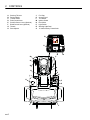
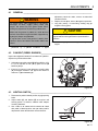
A. Steering Tilt Control
Pull lever to release steering column. Tilt column up or
down to position desired. Release lever to lock steering
column in place.
! CAUTION
Never adjust steering while unit ismoving. Stop unit and
set parking brake before adjusting.
B. Parking Brake Lock / Release
To lock parking brake, hold brake pedal (B) down and
press lock (B1) until it engages. To disengage, press
brake pedal release (B2).
C. Traction Pedal
Press front of pedal down forforward travel. Press rear
of pedal downfor reverse travel. Release pedal to slow
unit and stop. Allow unit to come to a complete stop
before reversing directions. Do not press traction pedal
when parking brake isset.
D. Rake Control Lever
Push forward to lower rake, pull back to raise rake.
NOTE: Never operate in reverse with rake down.
Rake may fold under unit and damage rake and unit.
M. Ignition Switch
The ignition switch has three positions. OFF - RUN START. See Section 6.4.
N. Hour Meter
Records engine operating hours. Use hour meter to
schedule periodic maintenance.
P. Light Switch
Controls operation ofwork lights.
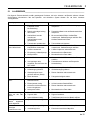
R. Warning Light Panel
Alerts the operator to conditions requiring immediate
action. See Section 2.3.
S. 12 Volt Accessory Power Outlet
Allows operation of approved 12 voltaccessories and
attachments. To prevent excessive battery drain, only
use 12 volt outlet with engine running.
! CAUTION
The 12 Volt Accessory outlet circuit is protected by a 10
Amp fuse. Do notattempt to use attachment(s) with a
combined power rating greater than 120 Watts.
To prevent the risk or burns or fire do not replace 10 amp
fuse with a higher amperage rating fuse.
E. Scarifier Lever (Optional)
Push forward to lower attachment, pull back to raise
attachment.
F.
2
Blade Control Lever (Optional)
Push forward to lower attachment, pull back to raise
attachment. To lock blade in float position, push lever all
the wayforward.
G. Throttle
Controls engine speed. Run machine at full throttle
during normal machine operation.
H. Seat Adjustment
Pull left side lever out to adjust seat forward or
backward.
J. Fuel Cap/Gauge
Displays fuel level. Read fueling instructions and the
engine manufacturer’s Owner’s Manual before
refueling.
K. Access Panel
Open panel toaccess hydraulic reservoir.
L. Tool Holder
A holder has been placed on each side of the hood to
store hand rakes, shovels,etc.
en-7