1
#
N,
rc,/
e13
AB'1290
AB1 21 60
4812210
AB2460
4824100
ABRC
'ätitilifrl:i'
STERLING
POWER PRODUCTS
Alte rn ato r-to-Batte ry
Ch
arge rs
and Remote Gontrol
(€
RoHS
complronT
ww\A/, sterl i n g - power, com
\ y'w\ /,sterling-power, uso,com
LrcnrnnascHrNEN-Blrrnnrn-LlnncnnAr
ErNslu- uNl BSITENUNGSANLETTuNG
Sicherheitshinweise
Vor dem Einbau und dem Betrieb lhres Sterling
Lichtmaschinen-Batterie-Ladegerätes lesen Sie diese
Anleitung sowie die Sicherheitshinweise auf dem Gerät
und den Batterien bitte vollständig durch. Nur eine gemäß
dieser Anleitung durchgeführte, korrekte lnstallation stellt
sicher, dass lhr Lichtmaschinen-Batterie-Ladegerät
optimal arbeiten kann.
Allgemeine Sicherheitsvorkehrungen
lnstallieren Sie das Gerät stets an einem trockenen, kühlen
und gut belüfteten Ort. Jeglicher Kontakt mit Wasser oder
großer Feuchtigkeit ist zu vermeiden. Sorgen Sie für
ausreichend Freiraum um die Lüfter des Gerätes, um es vor
Überhitzung zu schützen.
Stellen Sie sicher, dass alle Kabel ausreichend dimensioniert
und in gutem Zustand sind. Betreiben Sie das Gerät nicht mit
beschädigten oder ungeeigneten Kabeln.
Sicherheitsvorkehrungen gegen Gasexplosionen
Das Lichtmaschinen-Batterie-Ladegerät enthält elektrische
Bauteile, die unter Umständen Funken erzeugen können. Um
das Risiko eines Brandes oder einer Explosion
auszuschließen, daff das Gerät nicht in Räumen installiert
werden, in denen Batterien oder leicht entzündliche Stoffe
aufbewahrt werden oder welche explosionsgeschützte
Ausrüstung erfordern. Dies betrifft jeden Raum mit benzin-,
gas- oder dieselbetriebenen Motoren sowie jeden Raum mit
entsprechenden Tanks oder Leitungen.
Bevor Sie mit der lnstallation des Ladegerätes beginnen,
sorgen Sie für ausreichende Belüftung. Um die Bildung
explosiver Gase zu vermeiden, stellen Sie sicher, dass die
Batterien mindestens 4 Stunden vor Beginn der
lnstallationsarbeiten nicht geladen wurden.
Sicherheitsvorkehrungen beim Umgang mit Batterien
Wenn Sie in der Nähe einer Blei-Säure-Batterie arbeiten, sollte
stets eine zweite Person in Rufweite sein, die im Bedarfsfall
Hilfe leisten kann. Für den Fall dass Batteriesäure in Kontakt
mit Haut, Augen oder Kleidung kommt, sollte stets reichlich
Wasser und Seife in der Nähe bereitstehen. Tragen Sie stets
Augenschutz und schützende Kleidung. Vermeiden Sie
unbedingt, lhreAugen zu berühren, während Sie mit einer
Batterie hantieren.
Falls Haut oder Kleidung mit Batteriesäure in Kontakt
kommen, waschen Sie diese sofort mit Wasser und Seife aus.
Falls Batteriesäure in dieAugen gerät, spülen Sie diese
mindestens 10 Minuten unter fließendem, kalten Wasser aus
und suchen unmittelbar danach einen Arzt auf.
ln der Nähe von Batterien oder Verbrennungsmotoren darf
weder geraucht werden, noch mit offenem Feuer hantiert
werden. Jede Funkenbildung ist zu vermeiden.
Achten Sie insbesondere darauf, dass keine metallischen Teile
oder Werkzeuge mit den Batterien in Kontakt kommen. Dies
kann einen Kurzschluss verursachen, welcher unter
ungünstigen Umständen eine Explosion auslösen könnte.
Bevor Sie mit derArbeit an oder in der Nähe einer Batterie
beginnen, entfernen Sie alle persönlichen Gegenstände aus
Metall, wie z.B. Ringe, Armreifen, Halsketten, Uhren und
Schmuck. Eine Batterie kann bei einem Kurzschluss einen
hohen Strom erzeugen, welcher einen Ring oder einen
anderen Metallgegenstand stark erhitzen und schwere
Verbrennungen verursachen kann.
Laden Sie niemals eine gefrorene Batterie.
Allgemeiner überbtick
Das Sterling Lichtmaschinen-Batterie-Ladegerät ist ein
vollautomatisches, elektronisches Mehrstufen-Ladesystem zum
gleichzeitigen Laden zwei verschiedener Batteriebänke mit Hilfe
einer oder mehrerer Lichtmaschinen. Es kombiniert einen
fortschrittlichen Dioden-Ladestromverteiler mit einer
leistungsfähigen Verstärkereinheit. Das Gerät besitzt einen
Anschluss für einen oder mehrere Lichtmaschinen und zwei
Ausgänge zum Laden zwei verschiedener Batteriebänke.
Der mit "starter battery" bezeichnete Ausgang ist eine einfache mit
einer Sperrdiode versehene Durchleitung von der Lichtmaschine zur
Starterbatterie des Bootes oder Fahrzeugs. Zur Vermeidung
möglicher Regelungskonflikte mit der Motorelektronik wird die
Spannung auf diesem Ausgang nicht verstärkt.
Der mit "domestic battery" bezeichnete Ausgang arbeitet mit einem
intelligenten, softwaregesteuerten Spannungsverstärker, der die
Verbraucherbatterien bis zu fünf mal schneller und sehr viel
effizlenter als eine Standard-Lichtmaschine lädt. Darüber hinaus
nehmen die Batterien bis zu 50% mehr Ladestrom auf, was die
Nutzung ihrer vollen Kapazitäl erlaubt.
Das Lichtmaschinen-Batterie-Ladegerät sorgt für eine deufliche
Verbesserung der Ladung der Verbraucherbatteriebank. Dabei hat
jedoch die Starterbatterie stets Priorität, und das Gerät sorgt dafür,
dass diese zum Starten des Motors jederzeit ausreichend geladen
ist" Die Starterbatterie wird während des Ladevorgangs stets auf
einer Spannung von mindestens 'l3V gehalten.
Zusätzliche Funktionen des Gerätes schützen lhr Bordnetz und lhre
Batterien vor möglichen Fehlern wie überladung oder überhitzung.
Ein Systemfehleiwird durch eine Reihe von LE"Ds bzw. auf der
optionalen Fernbedienung angezeigt.
Wie das Gerät arbeitet
Das Lichtmaschinen-Batterie-Ladegerät maximiert die
Ausgangsleistung der Lichimaschine und zieht dabei deren
Ausgangsspannung auf ca. 1 3V herunter. Diese (bei hohem
Ausgangsstrom) anliegende, niedrige Spannung wird anschließend
im Gerät auf eine höhere Spannung verstärkt, welche sich zum
effektiven Laden von Batterien eignet, d.h" zwischen 14,2V und
14,8V. Dabei errechnet die intelligente Software automatisch den
optimalen Ladezyklus und die Ausgleichsladezeit. Wenn die
Batterien vollständig geladen sind, geht das Gerät in eine
Erhaltungsladung mit einer Spannung zwischen 13,5V und 13,8V.
Produktmerkmale
Einfache lnstallation: Es könnte nicht einfacher sein. Für die
Basisinstallation sind nur 4 Kabelverbindungen erforderlich: eine
von der/den Lichtmaschine/n, eine zu jeder Batteriebank und eine
zum gemeinsamen Minuspol. Mit Ausnahme der MinuspolVerbindung sollten die meisten dieser Kabel an Bord bereits
vorhanden sein.
Fortschrittliche Ladetechnik: I ntelligente, software-gesteuerte 4Stufen-Ladung der Verbraucherbatterien inklusive Temperaturkompensation.
Keine Konflikte mit der Motorelektronik: Weil das System die
Spannung der Starterbatterie nicht erhöht, sind Konflikte mit der
Motorelektron ik praktisch ausgeschlossen.
Keine Veränderungen an der Lichtmaschine: Die Lichtmaschine
muss nicht im geringsten modifiziert werden. Deswegen wird auch
die Garantie des Motoren- bzw" Lichtmaschinenherstellers nicht
beeinträchiigt.
Geeignet zum Anschluss mehrerer Lichtmaschinen: lm
Gegensatz zu anderen Systemen kann das LichtmaschinenBatterie-Ladegerät gleichzeitig mit mehr als einer Lichtmaschine
betrieben werden, was weitere lnstallations- und Kostenvorteile
bedeutet.
Priorität der Starterbatterie: Das System stellt sicher, dass die
Pluspol der Batterie! Die beiden dünnen Anschlussdrähte am
Starterbatterie stets einsatzbereit bleibt.
anderen Ende des Sensors schließen Sie an die mit "battery
lntelligente Schutzfunktionen: Das Gerät besitzt zahlreiche
temp" bezeichneten Geräteklemmen an. Achten Sie darauf, dass
Sie den Temperatursensor nicht beschädigen! Das System ist
nun in der Lage, die Batterietemperatur zu messen und die
Ladespannung entsprechend der für den gewählten Batterietyp
empfohlenen Temperaturkompensation anzupassen.
Sicherheitsmerkmale und Fehleranzeigen. Selbst bei einem
Totalausfall arbeitet das Gerät immer noch als Trenndiode.
Erweiterte lnstallationsmöglichkeiten : m Lieferumfang des
I
Gerätes sind Temperatursensoren für die Batterie und die
Lichtmaschine enthalten. Zusätzlich kann es mit der optional
erhältlichen Fernbedienung im Funktionsumfang erheblich
erweitert werden.
Basrsinsfa llation
Wichtig: Diese lnstallationshinweise beziehen sich auf die
Kabelverbindungen, die zur korrekten lnstallation des
Lichtmaschinen-Batterie-Ladegerätes erforderlich sind, Bei
einem bereits existierenden Bordnetz ist es ggf. erforderlich,
einige der bis dato genutzten Kabelverbindungen zu
entfernen.
lnstallieren Sie das Gerät an einer kühlen und gut belüfteten
Stelle in der Nähe der Lichtmaschine(n). Der lnstallationsort muss
trocken und vor starker Kondensationsfeuchtigkeit geschützt sein,
da das Gerät nicht wasserdicht ist. lnstallieren Sie das Geräi nicht
einem geschlossenen Kasten, da dies zu Überhitzung und
reduzierter Leistung des Gerätes führen kann.
Das Gerät besitzt drei temperaturgesteuerte Lüfter. Diese werden
häufiger arbeiten, wenn das Gerät an einer Stelle mit hoher
U mge bu ng stemperatu r mo ntie rt wi rd.
Bevor Sie das Gerät mit lhrer/lhren Lichtmaschine(n) verbinden,
überprüfen Sie, dass lhr Lichtmaschinen-Batterie-Ladegerät der
maximalen Leistung lhrer Lichtmaschine(n) entspricht.
Verbinden Sie den positiven Lichtmaschinenausgang (B+) mit
dem mit "alternator input" bezeichneten Geräteanschluss. Danach
verbinden Sie die beiden Ausgangsklemmen des Gerätes mit der
Starter- bzw. der Verbraucherbaiterie. Versichern Sie sich, dass
die verwendeten Kabel für den maximalen Strom der
Lichtmaschine(n) geeignet sind. Am besten wählen Sie eine
Kabelstärke, die mindestens für einen doppelt so hohen Strom
geeignet sind als eigentlich erforderlich. Wenn Sie z.B. eine 70A
Lichtmaschine haben, dann verwenden Sie mindestens ein 140A
Kabel.
Wenn Sie nur eine Batteriebank laden möchten, benutzen Sie nur
den Ausgang "DOMESTIC BATTERY". Der Ausgang "SIÄRf
BATTERY" kann frei bleiben, ohne dass die Funktion des Geräfes
beeinträchtigt wird.
Das Gerät besitzt einen kurzen, negativen Anschlussdraht (2), der
verlängertwerden muss und direkt mit dem Masseanschluss
(bzw. Gehäuse) der Lichtmaschine verbunden wird. Verwenden
Sie dazu ein 304 Kabel.
Wenn Sie zum Laden bisher eine Trenndiode verwendet haben,
dann sind die drei positiven Ladekabel bereits vorhanden.
Ersetzen Sie einfach lhre Trenndiode durch das LichtmaschinenBatterie-Ladegerät, und verbinden Sie den Masseanschluss mit
der Lichtmaschine.
Wichtig: Alle in dieser Anleitung angegebenen Spannungen
beziehen sich auf ein Umgebungstemperatur von 20"C. Bei
Ve nue n d u n g e i n e s B atte ri ete m p e ratu rse n so rs we rd e n d i e
tatsäch I ich e n S pan n u nge n aufg ru n d de r Te m pe ratu rkom pe nsation ggf. davon abweichen.
Lichtmaschinentemperatur: (10) Verbinden Sie das mit einem
Kabelschuh versehene Ende des Temperatursensors mit dem
Masseanschluss bzw. dem Gehäuse der Lichtmaschine.
Verwenden Sie dazu keinen positiven LichtmaschinenAnschluss! Die beiden dünnen Anschlussdrähte am anderen
Ende des Sensors schließen Sie an die mit "alt temp"
bezeichneten Geräteklemmen an. Achten Sie darauf, dass Sie
den Temperatursensor nicht beschädigen! Das System ist nun in
der Lage, die Lichtmaschinentemperatur zu messen; bei einer
Temperatur von mehr als '1 00"C schaltet sich der Verstärkerteil
des Lichtmaschinen-Batterie-Ladegerätes ab, bis sich die
Lichtmaschine wieder abgekühlt hat.
Spannungssensor: (7) ln der Basisinstallation misst das
Lichtmaschinen-Batterie-Ladegerät alle Spannungen direkt am
Gerät. Um einen möglichen Spannungsabfall zwischen Gerät
und Verbraucherbatterie auszugleichen, besteht die Möglichkeit,
einen einfachen 0,5mm' Draht als Spannungssensor zu
verwenden. Dieser wird zwischen dem Pluspol der
Verbraucherbatterie und der mit "dom sense" bezeichneten
Geräteklemme installiert.
Anlasser-Klemme: (4) Einige Lichtmaschinen benötigen zum
Starten eine Spannung an ihrem B+ Ausgang. Weil das
Lichtmaschinen-Batterie-Ladegerät eine Trenndiode enthält, liegt
am B+ Ausgang der Lichtmaschine jedoch keine Spannung an.
Der Motor lässt sich dann zwar starten, aber die Lichtmaschine
erzeugt unter Umständen keine Spannung. Zur Lösung des
Problems nutzen Sie die mit "starter solenoid feed" bezeichnete
Geräteklemme und verbinden diese mit derAnlasser-Klemme,
die während des Startvorgangs Spannung führt, d.h. während
der ca. 2 Sekunden, in denen derAnlasser betätigt wird.
Während dieser 2 Sekunden wird über das Gerät eine 12VSpannung an den B+ Anschluss der Lichtmaschine durchgeleitet, was im allgemeinen ausreicht, um die Lichtmaschine
starten zu lassen. Danach erregt sich die Lichtmaschine selbst.
Benutzen Sie für diese Verbindung einen 0,5mm2 Draht.
Anschluss mehrerer Lichtmaschinen: Das LichtmaschinenBatterie-Ladegerät kann mit mehreren Lichtmaschinen
gleichzeitig betrieben werden. Verbinden Sie einfach alle
Lichtmaschinen-Ausgänge (B+) mit dem LichtmaschinenEingang des Gerätes. Versichern Sie sich, dass lhr
Lichtmasch inen-Batterie-Ladegerät der maximalen
Gesamtleistung lhrer Lichtmaschinen entspricht.
Wichtig: Wenn lhre Lichtmaschine einen eigenen BatterieSpannungssensor besitzt, dann muss dieser vom Batterie-Pluspol
entfernt werden und stattdessen auf den B+ Ausgang der Lichtmaschine gelegt werden. Dadurch werden Regelungskonflikte
zwischen Lichtmaschine und Lichtmaschinen-Batterie-Ladegerät
ausgeschlossen.
Erweiterte
In
stal lation
Für erweiterte Funktionen und verbesserte Ladeleistung kann das
Gerät mit zusätzlichen Optionen installiert werden. Beachten Sie
bitte, dass die lnstallation dieser Zusatzoptionen für die korrekte
Funktion des Gerätes grundsätzlich nicht erforderlich sind.
Batterietemperatur: (6) Verbinden Sie das mit einem
Kabelschuh versehene Ende des Temperatursensors mit dem
Minuspol der Verbraucherbatterie. Verwenden Sie dazu nicht den
Fernbedienung: (5) Als optionales Zubehör ist eine
Fernbedienung lieferbar. Die Fernbedienung informiert Sie über
Spannungen, Stromstärken, Temperaturen und weitere
Kennzahlen. Ebenso werden auftretende Systemfehler
angezeigt.
Wahl des Batterietyps
Stellen Sie den Typ lhrer Verbraucherbatterie mit Wahlschalter (6)
ein. Das Gerät verfügt über Einstellmöglichkeiten für 8
verschiedene Batterietypen :
BATTERY TYPE
SELECTOR
POS 1: GEL USA - Batterien, welche in den USA hergestellt
wurden. Hier gelten abweichende Ladeschlussspannungen.
Ladeschlussspannung U1 bei '14,0V und Erhaltungsladung bei
13,7V.
POS 2: AGM USA - Einstellung fürAGM Batterien, welche in den
USA hergestellt wurden. Ladeschlussspannung U1 bei 14,35V
und Erhaltungsladung U2 bei 13,35V.
POS 3: GESCHLOSSENE SAURE - Einstellung für
geschlossene (nicht nachzufüllende) Blei-Säure-Batterien.
Ladeschlussspannung Ul bei 14,4V und Erhaltungsladung U2
bei 13,6V.
POS 4: GEL EURO - Einstellung für Gel-Batterien, welche nach
der europäischen Spezifikation von Exide gebaut wurden.
Ladeschlussspannung U1 von 14,4Y und Erhaltungsladung U2
von 13,8V. Besonderheit ist hier, dass die Erhaltungsladung U2
erst nach frühestens 12 Std. einsetzt. Das ist so von Exide
empfohlen.
POS 5: AGM EURO - Einstellung fürAGM Batterien nach
europäischen Standard. Ladeschlussspannung von 14,6V und
Erhaltungsladung von 1 3,7V.
POS 6: OFFENE BLEISAURE - Einstellung für Blei-Säure
Batterien, deren Verschlusskappen zum Nachfüllen von Wasser
geöffnetwerden können. Ladeschlussspannung U1 von 14,8V
und Erhaltungsladung U2 von 13,3V
Jetzt fängt die LEDI an zu leuchten sowie eventuell andere
LEDs, welche Störungen oder Stati anzeigen.
Nach Abschluss der Startphase brennt die LED 1 kontinuierlich
grün und zeigt damit an, dass sich das Gerät in der Hochstromladephase befindet und die Verbraucherbatterie eine verstärkte
Ladung erhält. Damit steigt gleichzeitig die an der Lichtmaschine
anliegende Last.
Die Spannung am Ausgang zur Verbraucherbatterie wächst nun
kontinuierlich bis zum Erreichen der Ladeschlussspannung für
den eingestellten Batterietyp. Danach wird die Spannung auf
gleichem Niveau gehalten (14,lV bis 15,1V); zusätzlich brennt
die gelbe "Time Control" LED 2. Die intelligente Software des
Gerätes berechnet automatisch die optimale Ausgleichsladezeit
(zwischen 1 und 24 Stunden).
Wenn die Batterien vollständig geladen sind, wird die Spannung
abgesenkt, und es liegt eine konstante Erhaltungsladespannung
an (13,3V bis 13,8V).
Sobald in der Erhaltungsladephase die Spannung der
Verbraucherbaiterie unter 12V absinkt (2.B. aufgrund einer hohen
Stromentnahme), beginnt der gesamte Ladezyklus von vorn.
Fehlersuche
Gerät zeigt keinerleiAktivität (keine LEDs)
Nachdem Sie die Maschine gestartet haben, überprüfen Sie die
Eingangsspannung am Lichtmaschinen-Anschluss des Gerätes.
Hier sollten mindestens 13V anliegen. Wenn Sie überhaupt keine
Spannung messen können, kann es sein, dass lhre
Lichtmaschine keine Spannung abgibt, weil sie zunächst extern
erregt werden muss. (Siehe "Erweiterte lnstallation".) Verbinden
Sie in diesem Fall die mit "STARTER SOLENOlD" bezeichnete
Klemme mit dem positiven Anschluss des Starter-Relais.
Wenn die Eingangsspannung am Gerät 13V oder mehr beträgt
und dennoch keine der LEDs leuchtet, prüfen Sie bitte die interne
Sicherung des Gerätes und ersetzen Sie diese, wenn
erforderlich. Falls die neue Sicherung anschließend erneut
durchbrennt, setzen Sie sich bitte mit dem Sterling Kundendienst
in Verbindung.
Wichtig: Schnelles Laden kostet Wasser! Prüfen Sie den
Gerät verstärkt die Spannung nicht
Wasserstand in lhren Batterien regelmäßig und füllen Sie Wasser
nach wenn erforderlich. Nicht zu viel Wasser einfüllen!
Die meisten Lichtmaschinenregler sind auf eine
Ausgangsspannung zwischen 13,6V und 14,4V eingestellt. Wenn
lhr Lichtmaschinenregler nicht innerhalb dieser Grenzen arbeitet
und die Spannung unter 13,3V regelt, kann das LichtmaschinenBatterie-Ladegerät die Spannung unter Umständen nicht
verstärken. Bitte reparieren oder ersetzen Sie lhren
Standardregler mit einem Regler, welcher diesen StandardAnforderung entspricht.
POS 7: KALZIUM-KALZIUM - Einstellung für Batterien mit einer
Silber Kalzium, Kalzium-Kalzium Legierung.
Ladeschlussspannung von 15,1V und Erhaltungsladung von
13,6V.
POS 8: DESULFATIERUNG - Einstellung nur für oflene BleiSäure-Batterien zur Desulfatierung der Bleiplatten.
Ladeschlussspannung U1 von 15,5V für4 Stunden. Anschließend
normale Ladeschlussspannung der Lichtsmaschine ohne Boost
Funktion.
Die optimale Ausgleichsladezeit für die einzelnen Batterietypen
wird mit jedem neuen Ladezyklus automatisch neu berechnet.
POS 9: OHNE BOOST - KEINE SPANNUNGSERHÖHUNG
ln dieser Funktion arbeitet das Gerät als normale Trenndiode
ohne die Spannung am Verbraucherausgang zu beeinflussen.
Einschalten und Test
Sobald das Gerät vollständig angeschlossen ist, erfasst es die
von der Lichtmaschine kommende Eingangsspannung. Wenn die
Lichtmaschine Spannung erzeugt, wird das LichtmaschinenBatterie-Ladegerät aktiv und zwar in folgenderAbfolge:
Zuerst wird die Softwareversion im Hexadezimalcode für 2 Sek.
angezeigt. Anschließend leuchten alle LEDs für 2 Sek.
Danach wird der eingestellte Batterietyp durch 1 LED für 5 Sek.
angezeigt. Die Batterietypenanzeige wird anschließend zur reinen
Spannungsanzeige.
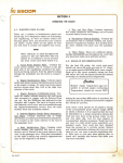
Anhang 1:
LED Anzeigen und Fehlermeldungen
LED 14 - BOOST (grün)
konsiant: Maximalstromladephase (LED 15 aus)
blinkend: Ladepause.
LED 15 - TIMER (gelb)
Die Ladeschlussspannung wurde erreicht bzw. wird in Kürze
erreicht. Sie brennt immer zusätzlich zu LED 1. Die
Ausgleichsladungsphase kann zwischen 1 und 24 Std. dauern, je
nach eingestelltem Batterietyp und berechneter Zeit.
LED 16 - FLOAT/POWERPACK (grün)
Die Augleichsladungsphase ist beendet und die Batterien sind
vollständig geladen. Sie bleibt an, bis das Gerät ausgeschaltet
wird bzw. bis ein neuer Ladezyklus beginnt.
LED 17 - HlcH VOLTS lN / OUT (rot)
konstant: Überspannung am Eingang von der Lichtmaschine.
Dies ist häufig ein Hinweis auf einen defekten
Lichtmaschinenregler oder eine andere Ladeeinheit.
blinkend: Uberspannung am Ausgang zu den
Verbraucherbatterien. Entweder ist der Lichtmaschinenregler
oder die Boost-Funktion dieses Gerätes defekt. Bleibt die
Spannung weiterhin sehr hoch, dann ist ein Defekt des
Lichtmaschinenreglers sehr wahrscheinlich.
Überprüfen Sie die Lichtmaschinenspannung; falls erforderlich,
stoppen Sie die Maschine so bald wie möglich und trennen die
Lichtmaschine vom Lichtmaschinen-Batterie-Ladegerät.
Andernfalls besteht die Gefahr, dass Sie lhre Batterien überladen
und zerstören!
3x blinkend - pause: Überspannung an der Starterbatterie.
Optionaler Anschluss für das Anlasser-Relais. (Siehe "Eniveiterte
lnstallation".) Nur im Bedarlsfall zu verwenden!
REMOTE DOM SENSE (7) (optional)
Optionaler Anschluss für den Spannungssensor der
Verbraucherbatterie. (Siehe "Erweiterte lnstallation".)
ALTERNATOR TEMP SENSOR {f S} (optional)
Optionaler Anschluss für den Lichtmaschinen-Temperatursensor.
BATTERY TEMP SENSOR (6) (optional)
Optionaler Anschl uss für den Batterie-Temperatursensor.
4x blinkend - pause: Hoher Spannungsabfall zwischen Ausgang
und Verbraucherbatterie
5x blinkend - pause: Zu hoher Spannungsabfall zwischen
Ausgang und Verbraucherbatterie. Boost ist abgeschaltet.
REMOTE CONTROL {5} (optional)
Anschluss für die optionale Fernbedienung.
LED 18 - H|GH TEMP TRIP (ON) / BOOST (FLASH)
konstant: Maximal erlaubte interne Temperatur wurde
140
l5
16a
170
180
überschritten. Das Gerät ist abgeschaltet und kann nur durch
einen Neustart wieder reaktiviert werden.
blinkend: Der Boost-Kühlkörper hat die maximal erlaubte
Temperatur überschritten. Der Boost Modus ist deaktiviert und
das Gerät im Standby, bis die Temperatur wieder auf ein
Normalniveau abgesunken ist.
t9
200
21 .
ln beiden Fällen überprüfen Sie unbedingt die Raumtemperatur
und die Belüftung des Gerätes. Überprüfen Sie, ob alle 4
Ventilatoren im Gerät funktionieren.
LED 19 - LOW BATTERY V (gelb-orange)
konstant: Die Eingangsspannung am Gerät ist unter 13V.
blinkend; Die Ausgangsspannung (Verbraucher) ist unter 13V.
Häufig ist dies ein Hinweis auf eine defekte Lichtmaschine oder
Batterie.
LED 20 - BAT TEMP HIGH (rot)
konstant: Die Batterie hat eine Temperatur von 55'C
überschritten. Das Gerät hat abgeschaltet und kann erst durch
einen Neustart wieder aktiviert werden, Überprüfen Sie sofort,
warum die Batterie zu heiß geworden ist.
a
o
o
o
o
blinkend: Die maximal erlaubte Lichtmaschinentemperatur von
90'C wurde überschritten. Das Gerät ist im Standby, bis die
Temperatur einen Normalwert erreicht hat.
2x blinkend - pause: Einer der 3 internen Temperatursensoren ist
defekt. Das Gerät muss zur Reparatur in eine Sterling
Servicewerkstatt.
LED 2'l - SENSOR FITTED I BAT TEMP OK (grün)
Batterietemperatursensor ist angeschlossen und die Temperatur
ist im erlaubten Bereich.
Anhang 2: Geräteanschlüsse
Stellen Sie sicher, dass alle verwendeten Kabel
ausreichend dimensioniert sind!
TO DOMESTIC BATTERY BANK
Anschluss für das positive Ladekabel zur Verbraucherbatterie.
MAIN ALTERNATOR INPUT
Positive Eingangsklemme zum B+ Anschluss der Lichtmaschine.
TO ENGINE STARTER BATTERY
Anschluss für das positive Ladekabel zur Starterbatterie.
NEGAilVE CABLE {2)
Verlängern Sie dieses Kabel zum Masseanschluss der
Lichtmaschine. Es sollte ein 60A Kabel verwendet werden.
STARTER SOLENOID {4} (optional)
Welche Kabeldurchmesser in mm'
bis
zu
0-25
25-45
45-85
85-125
125- 180
180 - 330
amps
amps
amps
amps
amps
amps
0-1 .5 m
mm'
mmz
mm2
mm2
mm2
mm"
Kabellänge
6
16
25
35
50
70
1.5 - 4 ß!
10 mm"
25 mm'z
35 mm2
50 mmz
70 mm2
90 mm2
Wenn Sie ein starkes Kabel nicht erwerben können, dann nehmen Sie 2x
das schwächere Kabel, Viele Probleme entstehen durch zu hohen
Spannungsabfall in den Kabeln. Deshalb entscheiden Sie sich bitte immer
für das stärkere Kabel.
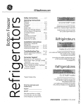
FnRxsnnrENUNG
ETNnau- UND BEDIENUNGSANLEITUNG
Fernbedienung (oploN)
ohne Funktion
mon ueller Anzeigenwechsel
outomotischer Anzeigenwechsel on/ous
Alormton on/ous
Geröt on / ous
Für die jeweilige Funktion
muß die Tqsle mind. t Sek.
gedrückl gehollen werden.
Wir danken lhnen für den Kauf der Fernbedienung für das
Sterling Lichtmaschinen-Batterie-Ladegerät. Mit dieser
Fernbedienung wird der Funktionsumfang des lhres
Lichtmaschinen-Batterie-Ladegerätes
nochmals erweitert.
Achtung: Vor Beginn der lnstallationsarbeiten müssen
Sie die Stromversorgung zum LichtmaschinenBatterie-Ladegerät unterbrechen, am besten durch
Abklemmen der Batterien und der Lichtmaschine.
Lieferumfang
Fernbedienung / Anzeige inkl. Aufbaurahmen.
Anschlusskabel für Fernbedienung, ca. 8m
Benötigte Werkzeuge und Teile
Stichsäge (bei Einbaumontage)
12mm Bohrer (bei Aufbaumontage
2mm Bohrer
4 Stk. 45x3mm Senkkopfschrauben
Kreuz-Schraubenzieher
Zweiadriges Telefon- oder Computerkabel als Messleitung
2) Montage als Einbaugerät
Entfernen Sie die Aufbaublende (B) vom Gerät durch Abziehen
nach hinten.
Diese Aufbaublende (B) benutzen Sie nun als Einbauschablone.
Halten Sie die Einbauschablone an den gewünschten Einbauort.
Jetzt zelchnen Sie mit einem Bleistift den inneren Ausschnitt
nach.
Sägen Sie den Ausschnitt sehr vorsichtig und genau aus, denn
die Abdeckung der Kante ist nicht sehr breit"
Anschließend verbinden Sie das Kabel mit dem Gerät, und dann
schieben Sie das Gerät in die von lhnen gesägte öffnung und
schrauben es mit 4 kurzen Schrauben mit Senkkopf fest. Achten
Sie darauf, dass die Schrauben versenkt sind, denn sonst passen
die Abeckkappen (A) nicht über die Schrauben. Abschließend
schieben Sie die Abdeckkappen (A) über die Schrauben.
3) Montage als Hinterbaugerät im Schaltpanel
Der lnstallationsort sollte außerdem leicht zugänglich sein.
Die Fernbedienung lässt sich alsAufbaugerät, als Einbaugerät
oder als Hinterbaugerät montieren:
Entfernen Sie die Abdeckkappen (A). Schneiden Sie einen
Ausschnitt von 'l34x90mm in lhr Panel. lm ldealfall benutzen Sie
dafür einen Laser, um eine absolut gerade Kante zu bekommen.
Das Panel sollte eine maximale Stärke von 3mm aufiryeisen. Bei
mehr als 3mm steht die Fernbedienung etwas zurück, was vom
Erscheinungsbild her nicht optimal ist. Anschließend bohren Sie
vier Löcher mit Senkungen zur Befestigung des Gerätes. Als
Schrauben dienen die vier bereits vorhandenen Schrauben mit
Senkkopf. Entsprechend müssen auch die Bohrungen und
Senkungen im Panel gearbeitet werden. Nach Beendigung dieser
Arbeiten entfernen Sie die vier Schrauben, schieben das Gerät
von hinten in den Ausschnitt und befestigen es anschließend
wieder mit den Schrauben.
1) Montage als Aufbaugerät
Anschluss des Gerätes
Bohren Sie ein Loch für das Kabel in die Rückwand. Anschießend
markieren Sie die Bohrlöcher für die Befestigungsschrauben.
Dazu schieben Sie die rechte und linke Abdeckkappe (A) seiflich
vom Gerät herunter. Bitte keine Gewalt anwenden, da diese aus
Kunstoff bestehen und die Führungsrillen brechen könnten. Jetzt
können Sie die Befestigungslöcher sehen. Markieren Sie die
Bohrlöcher und verbinden Sie die rückseitigen Anschlüsse mit
den Kabeln. Abschließend befestigen Sie das Gerät mit
geeigneten Schrauben.
Verbinden Sie das mitgelieferte Kabel mit der Fernbedienung. Auf
der Rückseite der Fernbedienung ist eine öffnung, hinter der sich
der Steckersockel befindet. Achten Sie bei der Verbindung auf die
korrekte Richtung" Die kleine Zunge auf dem Stecker muss nach
oben zeigen. Anschließend verbinden Sie das Kabel mit dem
Anschluss am Lichtmaschinen-Batterie-Ladegerät. Achten Sie
auch hierbei auf die korrekte Orientierung des Steckers (Zunge
oben).
Verlegen Sie das Verbindungskabel zwischen Ladegerät und
Fernbedienung nicht neben Leitungen, die 230V führen und auch
nicht neben Leitungen, die hohe Ströme leiten. Durch die Nähe
Ort der lnbetriebnahme
lnstallieren Sie die Fernbedienung an einem trockenen Ort.
Wählen Sie diesen Ort so, dass Sie jederzeit die Anzeige ablesen
und die Tasten bedienen können.
Wichtig: Der lnstallationsort muss trocken sein!
I
kann es zu Störungen in der Datenübertragung kommen. Es
handeli sich um eine reine Datenverbindung, die mit sehr
geringen Spannungen arbeitet.
Wir empfehlen lhnen dringend, dieses Kabel nicht zu kürzen. lm
Falle einerAuftrennung und Wiederverbindung des Kabels
erlischt die Gewährleistung.
Wenn alle Kabel korrekt verlegt und verbunden sind, stellen Sie
die zuvor unterbrochene Stromversorgung (Batterien,
Lichtmaschine) wieder her.
ANZETGEN (START UP )
HERSIELLERFIRMEN
co, 2 Sek
Kontoldoufnohme zum
Houptgeröt, Sollle
lönger ols ein poor Sek,
douern, donn
Sle bifie die Kobelverb,
Gerätefunktionen
Grundfunktionen
1) Ein- und Ausschalten der Ladefunktion
Durch Drücken der Taste power kann die Funktion des
Ladegerätes manuell ein- und ausgeschaltet werden. Auch bei
ausgeschalteter Ladefunktion bleibt das Ladegerät in
Bereitschaft, arbeitet jedoch nicht. Die Fernbedienung zeigt in
diesem Fall die Spannung der Verbraucherbatterie an.
Nach dem Einschalten des Gerätes zeigt das Gerät zunächst für
einige Sekunden die Software-Version des Ladegerätes und der
Fernbedienung an. Sollte es zu einem technischen Problem mit
dem Gerät kommen und Sie möchten uns kontaktieren, notieren
Sie bitte vorher die angezeigten Softwdre-Versionen.
Wenn Sie die Ladefunktion manuell ausgeschaltet haben, wird
diese bei einem Neustart des Motors nicht automatisch wieder
eingeschaltet.
Eingeslellter
Botterletyp
Lodestufenonzeige
und Sponnung
Siondard Anzeige
weileren lnformolionen drücken Sie bitte die
"Selecl" Toste für jeweils min. I Sek. Möchten Sie, doss die Anzeige
outomolisch wechselt, drücken Sie bilte die "Function" Toste.
Nun wechsell die Anzeige qulomolisch olle 5 Sek.
Zum Ausschollen dieser Funklion drücken Sie bitte nochmols die
"Function" Toste.
Zur Anzeige von
Noch dem Drücken
der "Function" Toste
Y
o
.'-,
I
tf
N
Anzeige der Lodestufe
und der Sponnung
"l
tIIJ
Anzeige nur, wenn in
Ausgleichslodung,
Anzeige der verbleiben
o
IJJ
den
Eingongssponnung
om Geröt
zlrJ
F
Verbroucher AusgongsSponnung om Geröt
1'ä
r.l
Storter Ausgongs-
-
HEä
<gLur
uvr6A
JZ-=
sponnung om Geröt
Verbroucherbolterie
Sponnung. Nur ongezeigt, wenn entspr,
Kobel ongeschlossen.
9F!FH
I
I
I
I
=ZEEJt11
z!r!+<+
ur=i=ö
ffäfiän
ouJLh=
tr;Pfrd
tr6'Hotr
Z.
--l'4-
Fr '+f'\
Anzeige der BoostLeistung,
-
at-Y=A
^üfi<*H
LrzmäuJ
3 ü.2\,8
öE;tu
lZJJ<
uru<<z
I\,4inuten
co. 5 Sek
=
ltJ
J
tr
F
_t
co, 2 Sek,
Produktinformalion
und Typ
€
IL
lnterne Geröletemperotur, Anze ge in
Fohrenheii und Celcius,
co, 5 Sek,
w
ry
co, 5
V
Sek,
V
co, 5 Sek
Anzeige der BotlerieTemperotur,
Nur wenn Sensor
ongeschlossen
ist,
V
co, 5 Sek,
co, 5
Anzeige der Lichtmoschinentemperotur
Nur wenn Sensor
ongeschlossen ist
Sek,
WARN. HINWEISE:
Diese Anzeigen sollten nur erscheinen, wenn es ein Problem beim Betrieb gibt.
Der Alqrmton konn durch drücken der Alorm Toste unterbrochen werden.
Sollten mehrere kritische Fehler quf einmol possieren, donn wird der wichtigste Alqrm ongezeigt.
w
@
Der Spannungsabfall zwischen dem Ausgang der Verbraucherbatterie und der Batterie selbst
ist zu hoch.
Der Boost ist abgeschaltet. Erhöhen Sie den Kabeldurchmesser.
Die Eingangsspannung ist zu hoch. Der Boost ist abgeschaltet. Wahrscheinlich ist der
Standard-Regler defekt. Stoppen sie sofort die Ladung der Batterien.
Die Ausgangsspannung ist zu hoch. Der Boost ist abgeschaltet. Entweder erzeugt ein anderes
Ladegerät eine erhöhte Spannung oder dieses Gerät ist defekt.
Die Temperatur der Batterie ist zu hoch. Stoppen sie die Ladung um eine weitere Schädigung
der Batterie zu vermeiden. Kontrollieren Sie die Temperatur der Batterie umgehend. Das Gerät
ist abgeschaltet.
Die Lichtmaschinentemperatur ist zu hoch. Das Gerät ist im Standby Modus und wartet auf ein
Abkühlen der Lima. Verbessern Sie die Kühlung der Lima!
Ein interner Temperatursensor ist defekt. Das Gerät muß zur Untersuchung in eine Sterling
Servicewerkstatt.
Die maximale interne Temperatur ist überschritten worden. Das Gerät ist abgeschaltet.
Überprüfen Sie die Belüftung.
Die normale Arbeitstemperatur ist überschritten worden. Das Gerät ist in Standby, bis die
Temperatur wieder im normalen Bereich ist. Überprüfen Sie die Belüftung des Einbauortes.
Die Starterbatteriespannung ist zu hoch. Da das Gerät keinen Einfluß auf diese Batterie h at,
schaltet das Gerät nicht ab. Überprüfen Sie sofort, warum so eine hohe Spannung an der
Starterbatierie anliegt.
Die Spannung der Starterbatterie ist sehr niedrig. Sotte die Warnung nicht erlöschen,
überprüfen Sie bitte die Batterie und die Verkabelung.
@
W
Die Verbraucherbatteriespannung ist sehr gering. Eventuell war die Batterie sehr stark
Entladen und braucht eine gewisse Zeit, bis die Spannung ansteigt. Erlischt die Anzeige nicht,
überprüfen Sie bitte die Kabel und Spannungen.
Die Eingangsspannung ist zu gering. Sollte diese Warnung anhalten, dann überprüfen Sie bitte
die Funktion der Lichtmaschine und des Standardreglers.
uolprnO4uoc
Äuo u; ouop
slr-l+
eq+ esoercul o+ MoH
lllds ord o Ou;sn lV ord o uror1 peOroqc quoq fue4oq Jo requrnu
o
o
o
o
o
NOl tl tO3 tdv SetN ]]V tdnsNl
lfIS^S
CIIS:IUOO
^Efl-IVE
l
o
re+eur +lo^ uo
seurooeq Äoldsrp 'p e'1
ell+ Jo uol+ces srql dn
fols reuo spuoces 00
B
sern+oel Ä1e;os repun
suor+cnr+su! ell+ ees esoe;d
7 ro 0 o
ecuenbes
L{sol1
ur 0urqsoll 'p'e'1 e0o11on q01q
I
eq+
lo lue^eeq+
ut-_l
I
W,
Wl
1o durag
pq/pafi$ rosues
dual 1oq
q61q
(ttsou)lno(uo)ur sllo^,v\ol
(ttspU)lsooq/(uo)dUt dure+ qOlq
(rtsouhno(uo)ul
..62
I
a.ezl
.'tzl
oiez
.. sz
'vz
..Itz
zz
'.'
,,
o
oz
6r.
oef
I
I
I
I
I
I
I
I
I
sllorr qOrt .lL
tpol] o 91
laurll 91
a Vl
lsoog
sruJBlE pue
uolleuJoluI.G'f '-l
Lou
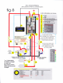
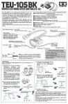
Norrv'r'rYrsNr lrsvfl
CNIUIA IAItrJSÄS WNIüNIIN
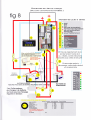
ANSCHLUSS. DIAGRAM
fig B
L.E.D. information
and alarms
14 o boost
'I
5
6
timer
o floqt
. 17 o high volls in(on)out(flosh)
['t a o high temp trip(on)/boosl(flosh)
'I
l9 low volls in(on)out(flosh)
I 20
o bot temp high
I
,t
. sensor fitted/bqt lemp ok
|
lr,'iW
lä,i.W
t'
I
Uo*--l
im Fole einer
Sponnung, bitie lesen
Sie
Einzelheiten in dieser Anlei-
B
30 Sek. noch dem Stort
wird diese Anzeige zu einem
Voltmeter
Battery
Temperatur
Sensor
Sensor
(beliesend)
t
Q
I
Verbraucher Batterien
Vergewissern Sie sich, doss
Anschlüssen
können I oder
2 Lichtmoschinen
ongeschlossen werden.
Die mqximole Leistung
des Gerötes dqrf nicht
überschrilten werden.
STARTER BATTERIE
_l
Es
-
ROTARY SWITCH FUNCTIONS
feiii,,=*-"
\Iq ;i;5i;;i*i;.
-
8) de-sulphation ( danger, read
MAX. CHARGING
VOLTAGE
14.0 v
-
10hrs
'l- thrs
1 - 12hrs
'14-r'lv
12
14.35
v
v
14.8 v
14.6
'15.1
v
J5.5 v
instructions before running
this cycle)
9) LtFEPO4
1
14.4Y
14-6 v
t1 1-
13.7 v
13.35 v
-24hrs
13.6 v
13.8 v
Shrs
Shrs
't3.3 v
6hrs
4 hrs
thr
13-7 v
13.6 v
off
13.8 v
Um mehrere Botteriebönke optimol mit dem Lichtmoschinen-Botterie-Loder zu loden,
konn dos Pro Splil eingesetzt werden,
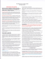
We are committed to customer satisfaction and value your business. lf at any time during the warranty period you experience a
problem with your Sterling product, simply call us on +44 (0)1905 771771 for technical support.
Sterling
Limited Two-Year Factory Warranty
Each Sterling product is guaranteed against defects in material and workmanship to the original consumer in normal use for 2 years
from the date of purchase. Sterling Power Products Ltd. will at its discretion repair or replace free of charge any defects in material or
workmanship. The following conditions apply:
.
r
Warranty is void if unauthorised repairs are attempted.
The customer is responsible for returning the product to Sterling Power Products Ltd. lnbound shipping costs are to be paid by
the customer.
.
This warraniy does not cover blemishes due to normal wear and tear or damages caused by accidents, abuse, alterations or
misuse.
r
Repairs not covered by this warranty can be done at the customer's request and expense.
Purchase or other acceptance of the product shall be on the condition and agreement that Steding Power Products Ltd. shall not be
liable for incidental or consequential damages of any kind. (Some countries do not allow the exclusion or limitation of incidental or
consequential damages, so the above limitations may not apply to you.) This warranty is made in lieu of all other obligations or
liabilities on the part of Sterling Power Products Ltd. Sterling Power Products Ltd. neither assumes nor authorises any person for any
obligation or liablility in connection with the sale of this product.
To make a claim underwarranty, contact Sterling Power Products Ltd.,8 Wassage Way, Hampton Lovett lnd. Est, Droitwich, WRg ONX,
United Kingdom. The customer has to provide a proof of purchase. Sterling Power Products Ltd. will make its best effort to repair or
replace the product, if found defective, within 30 days after return of the product to the company. Sterling Power Products Ltd. will ship
the repaired or replaced product back to the customer.
This warranty is in lieu of all others expressed or implied.
Vordringliches Ziel unseres Unternehmens ist die Zufriedenheit unserer Kunden. Falls Sie zu irgendeinem Zeitpunkt Schwierigkeiten
mit der Funktion oder der Bedienung lhres Sterling Produktes haben sollten, erhalten Sie unter der Rufnummer +44 (0)1905 771771
technischen Support.
Sterling
Zwe i -J ah res -H e rstel le rga
rantie
Jedes Sterling Produkt ist mit einer zweijährigen Garantie gegen Material- oder Fertigungsfehler ausgestattet. Diese beginnt mit dem
Tag des Verkaufs an den ersten Endkunden. ln einem berechtigten Garantiefall wird Sterling Power Products Ltd. das Gerät nach
eigenem Ermessen reparieren oder ersetzen. Dabei gelten die folgenden Garantiebestimmungen:
.
.
o
.
Die Garantie erlischt im Falle nicht autorisierter Reparaturversuche.
Es obliegt dem Kunden, ein defektes Produkt an Sierling Power Products Ltd. zurückzusenden. Der Versand muss frei erfolgen
Schäden, welche auf Verschleiß, Unfälle, unsachgemäße Nutzung oder bauliche Veränderungen zurückgehen, sind von der
Garantie ausgeschlossen.
Reparaturen außerhalb der Garantie werden auf Kundenwunsch gegen Berechnung durchgeführt..
Der Kauf oder sonstige Erwerb dieses Produktes erfolgt unter der Bedingung und Vereinbarung, dass Sterling Power Products Ltd.
keine Haftung für Neben- oder Folgeschäden jeglicherArt übernimmt. (Dies gilt nicht in Ländern, die solche Ausschlüsse oder
Beschränkungen nicht gestatten.) Gesetzliche Gewährleistungsansprüche werden hierdurch nicht berührt. Sterling Power Products
Ltd. übernimmt keine Haftung für Schäden, die im Zusammenhang mit dem Verkauf dieses Produktes stehen.
Zur Geltendmachung von Garantieansprüchen schreiben Sie bitte direkt an Sterling Power Products Ltd, 8 Wassage Way, Hampton
Lovett lnd. Est, Droitwich, WRg ONX, Großbritannien. Dem Schreiben ist eine Kopie des Kaufbeleges beizufügen. Sterling Power
Products Ltd. wird ein fehlerhaftes Produkt im Rahmen der Garantiebedingungen in der Regel innerhalb von 30 Tagen nach Eingang
reparieren oder ersetzen und an den Käufer zurücksenden.
Diese Produktgarantie ersetzt alle früheren veröffentlichten oder implizierten Garantien und Garantiebedingungen.
SrnntrrYc PowER PRqDUCTS LTD
Webs ite : www.sterl i n g-power.com
Emai I : [email protected]
Copyright 2008 by Sterling Power Products Ltd. Copying and reprinting not allowed.
Changes and errors excepted.
Ar-rnnxaroR-To-BATTERy CnaRcnn
INsrnucrroNs
Safety lnstructions
Product Characteristics
Before connecting and running your Sterling alternator-to-battery
charger, read the complete instructions and all cautionary labels
on the unit and on the batteries. Only a correct installation
according to these instructions will let you take full advantage of
your alternator-to-battery charger.
General Precautions Always install the unit in a dry cool and well-ventilated
place. Any contact with water and heavy humidity has to be avoided. Do not
cover the fans to prevent the unit from overheating. Make sure all cables
have the appropriate size and are in good condition. Do not run the unit with
cables that are damaged or olherwise inappropriate.
Precautions against Gas Explosions The altemator-to-battery charger contains
electrical components which may produce sparks in event of failure. In order
to avoid the risk of fire or explosion, do not install the unit in rooms
containing batteries or highly inflammable materials or in any place requiring
explosion-proofequipment. This includes any room with petrol, gas or diesel
driven engines or with tanks or piping used for any such substance. Before
starting to install the charger please ensue that there is sufficient ventilation.
In order to prevent the formation ol explosive gases make sure that the
batteries have not been charged for at least 4 hours prior to installation.
Precautions when Handling Batteries Someone should be within earshot, i.e.
close enough to come to your aid when working near a lead-acid battery.
Have plenty ofr.vater and soap nearby in case battery acid comes in contact
with skin, clothes or eyes. Wear complete eye protection and protective
clothing. Avoid touching the eyes while working with a battery.
lf battery acid contacts skin or clothing, wash immediately with
soap and
water. Il acid enters the eye(s), flood eye(s) with running cold water for at
least 10 minutes and seek medical attention immediately.
\ever smoke or allow
a spark or flame
in the vicinity of
a
battery or the
Easy installation: It could not be easier. For the basic system only 4 connections are
required: one lrom the altemator(s), one to each battery bant and one to the common
negative. Apad from the additional negative connection most ofthese cables will be
on board anlnvay.
Advanced charging technology: Intelligent, soffware-controlled, 4step charging
the dornestic banery including lemperature cornpensation.
of
No interference with engine electronics: Because the system does not increase the
voltage ofthe starter battery there is no risk olproblems with the electronic engine
management system.
No work on the altemator required: Absolutely no changes to the altemator
required. As a result no wamanty conflicts can arise.
are
Suitable for multiple altemators: Unlike other systems the altemator{o-battery
charger can be used simultaneously on more than one altgmator. saving even more
installation work and money.
Starter battery priority: The system ensures that the stafier battery is always kept in
operational condition.
Intelligent fault protection: The unit comprises multiple safety features and fault
indicators. Even in the unlikely event of a complete failure, the unit will still work
as
a split charge diode.
Enhanced installation options: The unit comes with temperature sensors for the
battery and the altemator. It can be enlanced by an optional remote control.
BaSiC lnStallatiOl? Important: These guidelines refer to the connection!
that have to be made for the conect installation of the Sterling Alternator-to-Batte:'
Charger. On an existing system you may also be required to remove some of the
original connections that were used to charge the batteries prior to the installatron rthe unit.
:ngine.
Work with extra caution to reduce the risk of dropping a metal tool onto a
':attery. It may create sparks or shorl-circuit the battery or other electrical
fJrts that may cause an explosion.
Remove all personal metal items such as rings, bracelets, necklaces, watches
and jew1ery when working near a battery. A battery can produce a short-circuit
iurrent high enough to weld a ring or any other metal which will lead to
serious bums.
\er er charge
a frozen battery.
General Overview
The Sterling altemator-to-battery charger is a fully automatic, electronic
multi-stage splitcharge system which charges two banks ofbatteries from one
or more alternators. It combines an advanced split charge diode system with a
powerful voltage ampliher. The unit has one input to connect to one or more
alternators and two outputs to charge two different battery banks.
The ouQut marked "starter battery" is a straight channel through a diode; this
is the channel that is connected to the boat / vehicle engine system. In order to
avoid any conflicts with an electronic engine management system, there is no
boost function on this chamel.
The output marked "domestic battery" comprises an intelligent, softwarecontrolled boost function which charges the domestic battery bank up to five
times faster and much more efficient than a standard altemator could do. In
addition, the batteries will take in up to 50% more charge current, allowing
you to utilize their full capacity.
While the altemator-to-battery charger greatly improves the charging olthe
domestic battery bank, the starter battery has always priority, ensuring that the
engine can be started at any time. Under no circumstances
allow the starler battery to drop below 13V
will the system
-\dditional functions protect your electrical system and your batteries from
possible faults such as overcharging or over temperalüe caused by the
altemator to battery charger. Any fault on the system will be indicated by a
::nber of LEDs or on the optional remote control unit.
_ , :: ..,..rrks
-.-- -:i;::o marimist the altemator
:.-.:::: c:-ls
,
output cunent, the altemator-to-battery
the altemator output voltage down to about 13,3V. Then this low
, -,:-: :s :::plified
to a higher voltage suitable lor effective battery charging,
: : ,-. :- :.S\. The unit's intelligent software automatically calculates the
: ::.:
-: ::-r;: c1cle and absorption time. When the batteries have been
- : -.::-::. --:: '. rrlra,qe is reduced to float voltage (appr. 13.5V to 13.8V) if
:,..:: : : :::,:::tr-i Lln rhe output voltage ofthe alternator.
:
.
Install the unit in a cool and well-ventilated position close to the altemator(s). Also.
the installation point has to be dry and free from hear,y condensation since the unit is
not waterproof. Do not fit it in a closed box as this might lead to overheating of the
unit and reduced perlormance.
The unit has three temperature-controlled fans. Therefore they will run more often
when the unit is installed in a place with a high ambient temperature.
Belore connecting the unit to your alternator(s) make sure that your altemator-tobattery charger is rated for the maximum ( combined ) output of the alternator(s ).
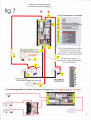
Connect the main altemator/ s output(s) (B+) to the center stud marked
"ALTERNATOR INPUT. Then simply connect the other studs to the engine banerl
and to the domestic battery respectively. Make sure that the cables used can carry
the full current ofthe altemator(s). Choose a cable size that can carry at least nvice
as much cunent than required. For example, ifyou have a 70A altemator, then use :
140A cable to reduce voltage drop in the cable and improve performance
Ifyou are only going to charge one bank ofbatteries, then use the "DOMESTIC
BATTERY" output only. The "STARI BATTERY" ouQut can temain unused
without affecting the performance of the unit.You can split the boosted domestic
battery side by using a Sterling Pro Split R 0 volt spliting system or the Current
limitingVSR.
The unit has a shorl negative wire which has to be extended and connected directll
to the altemator negative (or case) or the cofilmon battery neg using a 604 cable.
If you cunently have a split charge diode, then the three positive wires are alreadl
there. Simply replace the split charge diode with the alternator-to-battery charger a:d
connect the negative wire to the altemator neg or the nearest main comm neg.
Important: Ifyour alternator has got its own battery voltage sense wire, then this has
to be removed from the battery terminal and should be connected to the altemator's
own B+ output instead. This will prevent contradictory regulation between the
altemator and the altemator-to-battery charger.
Extended Installation
For additional functions and improved perfonnance some extra features can be
installed. Note that this extended installation is optional and is not required lor the
unit to work.
Battery Temperature: Using its ring teminal end, comect one of the enclosed
temperature sensors to your domestic battery's negative post. Do not use on thc
positive battery terminal lor this connection! Connect the two small wires on the
other end to the small tenlinals marked "battery temp". Be careful not to damage or
alter the temperature sensor in any wayl The system will then sense the banery
temperature and change the ouQut voltage in accordance with the recommended
temperature compensation lor the selected battery type. Thc temp sensor does not
nced to be uscd lor thc unit to work,
Impofiant: All voltages indicated in these instrrrctions refer to an ambient
temperature of 20'C. When using a battery temperature sensor these voltages
will
be
different due to temperafure compensation.
Alternator Temperature; (10) Using its ring terminal end, connect one ofthe
enclosed temperature sensors to your altemator case or negative stud. Do not use
any positive terminal (B+) for this connection! Connect the two small wires on
the other end to the small terminals marked "alt temp". Be careful not to damage
or alter the temperature sensor in any way! The system will then sense the
altemator temperature and will disengage the voitage ampliher if the altemator
temperature exceeds 100oC.
Voltage Sensing: (7) The altemator-to-battery charger in its standard
configwation senses all voltages directly at the unit. However, in order to
compensate a possible voltage drop between the unit and your domestic battery,
you can run a simple 0.5mm'wire from the positive stud of your domestic battery
to the terminal marked'odom sense".
Starter solenoid: (4) Some altemators will not fire up without a voltage on their
B+ terminal. Because the altemator-to-battery charger gontains a split charge
diode there will be no voltage feed on the B+ terminal which means that the
engine will start but the altemator may not work. If this is the case, then simply
comect a ignition feed ( from the key switch ) which becomes live when the
engine is started. this will feed 12 v through the unit and fire up the alt
Multipie Altemators: The altemator-to-battery charger can be used on trore than
one alternator at the same time. Simply connect all alternator outputs (B+) to the
aitemator input terminal on the unit. Make sure that your aitemator-to-battery
charger is rated for the combined maximum outpüt of the altemators.
Remote Control: (5) The remote conkol kit is an optional extra
The remote control wiil keep you informed about voitages, currents, temperafures
and other operating figures. In the event of a problem, it indicates what the
problem is.
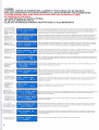
Battery Type Selection FIG 7/8
Program the type ofyour domestic battery into the unit by using the rotary switch
(6). The unit has 8 different battery type settings and a de sulphation setting:
Batter Type Selector, for 24 v x voltages by 2
Switeh
setting
Boost
0) to be used by factory for set up
t+
1)Gel usa
Float
t3.'l
14.1. 13.4
3)AGM 2
14.6 t3j
4;sealed leadacid
14.4 13.6
S)gel ewo
14.4 13.8
6)open lead acid
14.8 t3.3
7)calcuim
15,1 13.6
15.5 4 hrs then off
8)de sulfation
9)LiFeP04
14.8 v I 3.8
2}AOM i
1) {ie1 U.S. spec. l:loosi 14.0\r. Tine i - l0 hls, Float 11.7V
American gel manufactures want a different charging regime than the European
ones. If in doubt ask the baftery supplier.
2) ÄGM U.S. spcc. Binst 1.tr.-15!. |'iure 1 - 8 hrs. Floal l-1.-l5v
This is the setting which most American AGM battery manufacturers would
like. Ask your battery supplier for the gorrect setting as this is a new battery type
which is becoming more and more popular.
3) Sealcd Lcad-Acid Bocst 14.:1V. Tirne I - l2 hrs, Float i3.6V
Sealed lead-acid batteries are simply lead-acid batterios which have no access to
top up the water level.
4) Iluropean Gei ,r liriirle spcc. Boost t;tr.4\i Jure 12 - ?4 hrs" Irltiat ll.8V
This program is, as per the recommendation of Exide, set at a voltage of 14.4
volts for about 12-24hrs. The unit then drops to float voltage to maintainlhe
batteries.
5) liuropeanAGM spec. I]oost 14.6V, l'inte I - 8 hrs, Float l-l.lV
This is what the European AGM suppliers such as Optima want for their
batteries. Again we would strongly recommend you contact your battery
supplier to confirm which charging option they require for their batteries. This
higher voltage appears to be for AGM batteries with a highdr calcium content on
the plates.
6) Open Lead-Acir1 Boost 14.8V Timc I - 8 trrs, Ploat l-1.3V
or sealed lead-acid batteries, where you can unscrew the lid ofthe battery and
are able to top it up with water, The maximum boost voltage for this fype of
batteries is 14.8V.
7) Calciunr-Calciurn (Jiqr-rid lead-acirl): tr]ocst l5.lV. Time 1 - 6l.rrs, Itloat
13.6V
Some modern batteries have had calcium added to their plates in order to reduce
water loss in the battery. The down side with this is that you need a high charge
voltage to get the batteries charged. This setting goes up as far as 15.1 volts on
boost and can have a detrimental effect on voltage-senstive equipment on the
boat/vehicle. It is important to ensure that your equipment works safely at a
voltage in the region of 15.4 volts (x2 lor 24V systems) before selecting this
option, most equipment does but not all.
8) Ile-suiphatir:rr Selling: lloost LE.5!', Timc 4 hrs, Float none/otT.
WARNING: This is a very dangerous setting if used without understanding what
it does. First of all, the batteries should be isolated lrom the boat's system as the
voltage will be pushed up close to 16 volts which will damage some onboard
equipment. The reason why you would engage this charge mode is to blast the
sulfation off old or unused batteries to regenerate them. It will probably need to
be used on an old set olbatteries which are not charging or holding a charge.
This program will help a lot to remove the sulfation from the plates. It is
unlikely this setting would need to be used when the batteries are still new. Do
not use this setting on sealed, gel or AGM batteries as they will gas and you will
be unable to replace the water loss! DO NOT USE ON LIFEPO4 BATTERIES
9) LiFePO4 Lithium batteries, this is a charge
BATTERY TYPE
SELECTOR
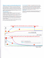
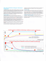
tsaltery C-harging lerminology: We use the word Boosi,/ fast charge which then
becomes absorption or equalising charge, to describe the fißt and second stage
ofthe charge cyc1e. A1i it means is that the charger is offering the boost voltage to
the batteries (and the batteries will absorb a1i the current up to the max curent of
the charger) for as long as possible. Then the current will taper off. After a period
of time the voltage will drop to float. This is a voltage which will mailrtain your
batteries and aiso allows the system to act as a power pack to supply power being
used on the boat or vehicle without touching the newly charged batteries- The
time on boost is determined by the state of charge of the battery bank and the
ratio ofyour battery bank size and the size olthe charger. The intemal software
program works this out every time the charger is used and will vary within the
paramgters shown as time.
Fuses
: Because the instructions refer
to 12V
of
as
14.8 volts and a {loat
well
of I 3.8
as 24V units between 100
and 200 amps and there are a lot of different fuse possibilities and cornbinations,
it is simply not possible for us to recommend any fuse values. This will be up to
the installer. However, here are a few key issues to remember when choosing a
fuse;
1) In most cases a fuse is there to protect the cable not the product, so always
fuse 50% pius on the product rating. For example, if the altemator is a 100 amp
altemator then fuse about 150 amps etc
2) Too small a fuse in an alternator line can cause major problems. If, for
example, you have a 100 amp altemator and you only put a 100 amp fuse on,
then on start up and when coid, a 100 amp altemator can produce about 120
amps. This will blow the fuse and because you have open circuited the
alternatoq this wili result in the destruction of the altemator. So it is vital that an
alternator cannot blow its fuse under normal operating parameters as this will be
an expensive mistake. Always fuse higher rather than to low
WHAT CABLE TO USE lN sq mm
A charger or inverter up
amps
2545 amps
45-85 amps
85-125 amps
125- 180 amps
180-330 amps
0-25
to
cable run distance 0-1.5
6 mm sq
16 mm sq
25 mm sq
35 mm sq
50 mm sq
70 mm sq
rntr
1.5 - 4 mtr
10 mm sq
25 mm sq
35 mm sq
50 mm sq
70 mm sq
90 mm sq
Please note that if there is a problem obtaining for example 90 sq mm cable,
simply use 2 x 50 sq mm or 3 x 35 sq mm. The cable is simply copper, and
all you require is the copper. ll does not matter if it is one cable or 10 cables
as long as the cross-section adds up. Performance of any product can be
improved by thicker cable, so if in doubt round up,
o oo o o
-
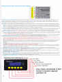
The battery type l.e.d.s display 2 different sets of information
unit first starts up the 1.e.d.s show the battery type selected for the first 30 secs.
2) after 30 secs this block of l.e.d.s becomes volt metre showing the voltage at the ouQut of the unit
this allow you to access if the unit is working correctly, ie after a few minuets on start up the l.e.d.s
should progress up to the preset voltages set by the Battery type adjustrnent. this could take a few
minuets to a few hours depending on the size and state ofthe battery bank
1) when the
The LED meanings and functions (fig 8)
14
o
l5
l6 o
o
l8 o
17
l9
20
o
21
o
14) BOOST / HIGH CHARGE RATE ON: Green: This should be on from start-up (a slow flash shows that the unit is on but on standby, ie the high alt temp trip
or some other trip has switched the boost aspect ofland the unit is waiting to reset if possible). When this LED is on continuously this shows that the sysrem
should be working at it's maximum to achieve the full preset desired output voltage . It should remain on until the green float comes on and this shows the high
charge rate is complete.
15)TIMERON:Yellow:TimerActivated:Thiscomeson,whenthevoltagereachesaboutl3.9-14vo1ts(x2for24v)anddependingonhowlongittooktoachieve
this voltage from start up will dictate how long the timing cycle will remain on. The soltware will calculate the timing for the high charge rate. This will vary fiom
- 10 hours and the time will be displayed on the remote panel as a count down . This light will remain on until the high charge rate is over, and will go out at the
same time as the high charge rate between 1-6 hrs after activation. (a slow flash shows that the
has switched the boost aspect
1
unit is on but on standby, ie the high alt temp trip or some other trip
offand the unit is waiting to reset ifpossible)
16) FLOAT: Green Float Mode: This indicates that all the high charge cycles are now over and should remain on after all the high charge lights are out. The system is
now running at a standard float voltage rate only (about 14 volts) regulated on the battery (a slow flash shows that the unit is on but on standby, ie the high alt temp
trip or some other trip has switched the boost aspect offand the unit is waiting to reset ilpossible).
17) HIGH TEMPERATURE. red: ( L.E.D. on solid ) This device monitors both heat sinks and in the event of that exceeding 75 deg C the unit will switch olluntil the
temperature has been reduced. It is important not to fit the unit inside a hot engine room or somewhere with no air flow round the unit total unit shutdown, auto reset
on unit temp dropping below 65 deg c
( L.E.D. Flashing constant ) and the cunent lights flashing, this means the boost has been switched off ( to reduce the heat being produced on the heat sink, if the temp
keeps increasing then the l.e.d. will come on solid and trip the unit completely , as such the unit is on standby waitrng for the temp to reduce
18) HIGH VOLTS lN ( ON ) / OUT ( FLASH ) :( L.E.D.on solid ) This will wam you and switch off the boost section, this means that your alternators own regulator has
lailed and the altemator will now boil and destroy your batteries, there is simply nothing we can do about this except wam you:
please take this warning very seriously and stop your engine as soon as possible, remove the alternator input cable to prevent damage to your batteries then
continue yourjourney and have the alternator inspected and repaired at next available place. this is a fatal warning and should not be ignored
Battery output voltage high ( L.E.D. on flashing continually )This will warn you and switch off the boost section, this means that either this unit has failed
and was in the process of overcharging your battery bank, or you have some other charging source on your output battery bank which is overcharging the
batteries and our unit thinks it is at fault ie ifthere was a battery charger or solar cell which was putting out a voltage in excess of 1.5 volt above the boost
voltage ofeach ofthe different battery types. this is a fatal trip and the unit will not come back on again until reset, ie engin switched offand on again
led 2 flash, high internal voltage, latal flaw , unit defective and must be returned
led 3 flash, group high voltage starter battery, warning only no action by our unit
led4flash, highvoltagedropfromunitoutputtotheendoftheremotesensingcable,thisisduetoeithertosmallacable,tolongarun,detlectivecrimping
fatal , find fault and fix , max voltage drop between unit output and cable end is 0.8 volts this is a warning but no action from our unit
led 5 flash short circuit on output, the parameters are , voltage below 6 volts and current in excess of 100 amps ( the software will take this as a short circuit )
19) LOW VOLTS IN ( ON y OUT ( FLASH ) yellow: Low Input Voltage Warning: (LED on solid ) This is simply saying that there is a 1ow voltage at the altemator input
and has no active function. For infotmation only, this usually indicates a defective altemator or lose cable , it could also be simply very high demand at 1ow r.p.m.
Battery output low voltage: Low Voltage Waming: (LED flashing ) This is saying that there is this could simply be that the output batteries are so flat that it could take a
, or cable broken. not
few hrs to build up the voltage , or the unit is delective and unable to charger the batteries
Low Starter battery 2 flash thenpause etc etc
20) HIGH TEMP TRIB ON / BAT ( FLASH / ALT ) Red : This shows that the battery temperature sensor has picked up a temperature in excess of 50 deg C at its source (
where ever you have fitted it ) this will trip the unit until it has been reset. Please find the fault belore resetting, it could be a hot defective batter or a lose termrnal near the
temp sensor which has overheated the terminal giving the sensor a false temp reading , the unit processes taking this reading as the actual battery temp .
21) SENSOR FITTED/BATTERY TEMP OK this confirms that the battery temperature sensor is fitted and that all is o.k., if the sensor is not fitted this l.e.d. $'ill ec. ..ur=
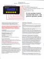
REMOTE CONTROL (oPnoN)
scroll
outomotic scroll on/off
switch olorm offlon
switch unit off monuolly
for qll commonds
pleqse hold the button
for qbout I sec
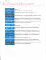
SCREENS (START UP
COIVlPANIES INVOLVED
IN THIS PRODUCT
Optional Remote Control
Place oflnstallation
ABOUT 2 SECONDS
V
CON/S SIGNAL,IF N/ORE
Imporlant: The panel must be installed in a dry place!
The remote panel can be flush-mounted or top-mounted with or without frame:
PRODUCT INFORIVATION
]VODEL TYPE
l) Top-Mounting with Frame
Drill a hole for the wires into
the back board. Slide the smal1 left and right hand
covers (A) offthe front panel which will expose the screws. Unscrew, remove the
frame (B) and drill the required holes into the back board. Connect all necessary
wires to the correct terminals at the back of the unit. Mount the unit using the
frame (B) and suitably long screws onto the back board.Reattach the covers (A)
onto the front panel.
SHOWNG INFORI\IATION
ON THE BATIERY ryPE
SETTING, TO CHANGE
ADJUST BATIERY ryPE
POT
2) Top-Mounting without Frame
Slide the small left and right hand covers (A) olf the front panel which will
expose the screws. Unscrew and remove the frame (B). Use the inside of the
frame (B) as a template for the required cutout in the back board. Carefully cut
out the back board and connect al1 necessary wires to the correct terminals at the
back ofthe unit. Mount the unit using the four shorl screws supplied and reattach
the covers (A) onto the front panel.en.
3) Flush-Mounting
Remove the small left and right hand covers (A) off the front panel and make a
cutout of 134mm x 90mm into the back board. Ideally, the back board should not
be thicker than 3mm; otherwise the front panel will stand back a 1itt1e. Using the
actual Power Ma"nagement Panel as a template, drill the required holes with
counterbores into the back board. Connect all necessary wires to the coffect
terminals at the back of the unit. Push the unit from behind into the cutout and fix
it with the screws provided..
STATE
@
ABOUI 2 SECONDS
SHOWING THE CHARGE
& VOLTS
IE
FASI/ADSORPTION/F LOAT
CHARGE,
DEFAUIT SCREEN
Connect the supplied remote control cable with the remote control unit. On the
back of the remote panel is a small opening with a socket behind. Mind the
correct orientation of the plug when you connect the cable. The small clip on top
of the plug must be dilected upwards. Then, connect the remote control cable
with the corresponding connector on the altemator-to-battery charger. Again,
mind the correct orientation of the plug! (c1ip on top).
Avoidifpossible laying theremotecontrolcablenexttoany230voltsa/ccables
or next to high current d/c cables. This may cause interference and erroneous data
transmission. Remember, the remote control cable is purely a data transmission
working on r ery low voltages.
Ifyou cut and reconnect the
SCROtt THROUGH, AtL VOLTAGE READINGS BETOW ARE JUST EXAMPLES
TO STOP THE AUTOMATIC SCROTLING AND LOCK ONTO ANY OF THE
BELOW SCREENS THEN SIMPLY PUSH THE FUNCTION BUTTON AGAIN
THE SCREEN WILL SAY SCROLT OFF AND LOCK ON THE SELECTED SCREEN
AND
AFTER YOU PUSH THE
FUNCTION BUTTON
WHAT PART OF THE
CHARGE CYCLE ]HE
UNIT IS CIJRRENTLY
ON
AND THE VOLTAGE,
IE
WHEN THE CYCLE IS
ON ADSORPTION
I\4ODE, THIS IS THE COUN
DOWN TIMER UNTIL
IT GOES ONTO FLOAT
*uffifrN**w
ABOUT 5 SECONDS
DOIV]ESTIC OUTPUT
VOLTAGE AT OUR STUD
off
The alternator-to-battery charger can be switched on and offmanually by
pressing the orVoff key ( assumming the altemato is working. Even when the
charger has been switched off, it will remain on standby mode. Also, the batteries
will sti11 be charged, but without the boost on the domestic battery side.
After the unit has been switched on, the remote control will show the software
release ofthe charger and the remote control unit. In case you are experiencing
problem with your altemator-to-battery charger, please take a note of these
a
numbers before you contact us.
When the engine is restarted, the altemator-to-battery charger will also restart,
even when the charger has been switched off manually before.
REFERS TO THE STARTER
BANERY VOLTAGE
TAKEN AT OUR UNITS
]ERMINAL
REFERS TO THE
BATTERY
BANK VOLTAGE
IF THE REIVOTE SENSE
WIRE IS USED ONLY IF
NOT USED THEN NO DATA
SHOWING BETWEEN
2) Alann Sound
I
The alam sound indicating any system faults can be muted using the alarm key.
EFFECTIVE BOOST
3) Background Light
l0O%
The background light of the display panel can be switched on and offusing the
light key.
BOX INSTALLATION INSTRUCTIONS
SLIDE PARTS A TO EXPOSE SCREW HOLES
FOR FLUSH MOUNT, REMOVE PART B
FOR SURFACE MOUNT KEEP PART B
AFTER INSTALLATION REPLACE PARTS A
I
I OO% THIS IS THE
%:
LITTLE
=
WORK
MAXWORK
UNIT TEIVIP SHOWN
IN DEGREE C AND IN
DEGREE F THE UNIT WILL
SWTCH OFF AT 80 DEG
ALTERNATOR TEMP
IF SENSOR FINED. IF
SENSOR NOT FITIED THEN
NO SENSE.
BATTERY TEMP
IF SENSOR FITIED, IF
SENSOR NOT FITIED THEN
€
V
FAST/ABSOR BTION/FLOAT
When all cables have been correctly laid and connected, reconnect the batteries
and the altemator.
Basic Functions
V
FOR MORE INFORMATION PUSH THE FUNCIION BUTTON ON THE
REMOTE CONTROL. AND THE SCREENS WILL AUTOMATICATLY
ABOUT 2 SECONDS
Installation of the Remote Control
A*
V
THAN A FEW SECONDS,
CHECK THE LINK CABLE
AND CONNECTORS
The installation location should be accessible easily.
We strongly recomend not to shorten this cable.
cable this may void the warranty olyour unit.
ABOUT 2 SECONDS
SEARCHING FOR THE
Install the remote control panel in a dry place and in such away that you can
easily read the display and access the confol buttons.
1) Switching the charger on and
)
NO SENSE,
V
ALARMS:
A LOT OF ALARM AND SAFETY FEATURES.
UNDER NORMAL RUNNING THEY SHOULD NEVER COME ON.
THE ALARM BUZZER CAN BE SWITCHED OFF BY
PUSHING THE ALARM BUTTON ON THE REMOTE CONTROL,
THE ACTUAT ALARM WIIL REMAIN ON THE SCREEN.
IN THE EVENT OF SEVERAL ALARMS HAPPENING THEN
THEY ARE PRIORITIZED TO SHOW THE WORST ONE
THE UNIT IS FITIED WITH
IF THE VOLTAGE DROP
BEMEEN THE UN
THE
DOM
T
OUT &
BAT ( IF SENSE
)
WIRE IS USED
EXCEEDS
I ,6 V, THERE IS A CABLE
PROBLEI\I
THE STANDARD ALT
S
REG IVUST HAVE FAILED
LS PUSH NG OUT IN
AND
EXCESS
OF I5,5 V
AIARM IN THE EVENT OF
THE OUTPUT VOL]AGE
BEING
I
VOLT ABOVE THE
D PROGRAIV] I\1ED
VOLTAGE
DESIRE
SENSOR READING IN
EXCESS OF 55 DEG C
COULD BE HOT BATTS
OR LOSE CONNECTION
ON TERIV]INAL
ALT TEIV]P SENSOR
SENSING IN EXCESS OF
90 DEG C AT THE ALT
ONE OF THE 3 INTERNAL
TEMP SENSORS HAS
FAILED
A WARNING
YOUR DOI\,4ESTIC
BATTERY CABLE IS
TO TH N OR N/AYBE
LOOSE
THIS IS
THAT
Cob e thickness is very imporionl to ovoid to much volloge drop ot high currents. This could leod to o fiie in the
coble ts olwoys o good deo to test the unit at full power ond feel oll the bottery cobles, if you hove problems
touching the coble then the temp will be n excess of obout 50 deg C ond this s getting to hot, odd more cable
to reduce the v drop ond the temp Vvill olso drop
The usuol only woy this con hoppen if the olternotors stondord reg hos fo led ond 10 much vo toge s being
produced ol the olternotor, ihis is o serious event ond requires the engine to be switched off os soon os poss ble
to prevent domoge done to the syslem, we connoi stop this, only worn you, if you ore somewhere where you
connot f x this problem, then pleose stop the engine os soon os possib e ond remove the olternotor output
coble or the olternotor drive belt before continu ng on sort the o t os soon os possible
The usuol only woy this con hoppen if the olternolors sfondord reg hos folled ond 10 much voltoge is being
produced ot the oliernotor, ( os obove ) however its poss ble the o ternotor is ok but ihe olt to bottery chorger
regulotor hos foiled in some woy ond !1s going to domoge / over chorge your botteries, in this cose when
the frip is octivoted the voltoge should drop down to within sofe limlts ( oboul l4 volts I the unit is then defective
foult s ntended to show high bottery iemp in excess of 55 deg c, however other foctors con tr gger this
olorm, for exomple o lorge omount of current going through loose/ smoll coble con couse the iemperoture on the
bottery stud ( where the temp sensor is connecled )to over heot, this con set the olorm off, so in the event of thjs
olorm octivoting, visit the termino n queslion os soon os possible ( wthin a minuet or so ) ond confirm if the botteries
ore hot or s mply the term noL, in which cose fix the terminol/wiring to stop this
This
foult s lnlended to show high temp ot the olternotor, if this keeps golng off then you shou d consider piping
cold oir in oround the bock of the olternotor, the olternoior will then suck ihe oir from the bock of the o t throuoh
to the froni , this will dromoticollv cool the olt down
This
There ore 3 internaL temp sensors contro ling the fons ins de our unil jn the event of one of them foiling then this
olorm wl sound, it would be o good deo to return the unit for service
This js the first stoge worn ng thot the voltoge drop down your moin domestic coble between the un;t ond the
domestic bolter es ls geiting to much ( ossuming the remote sense wire is connected ) ond you should be
looking ot ncreosing the omount of copper on thot run of coble { ie double it up ) , if the voltoge drop goes
over 8 volts then the unit will tr p ( see obove olorrn l
I
IF UNIT TEN/P EXCFEDS
80 DEG C
THEN
]T
WLL SWITCH OFF IHE
This
olorm is os it stotes, the unlt is gefiing to hol ond hos switch off, moke sure the unit s jn o venU oie spoce
e y coo , not in o engine room or o seoled cupboord, You moy need to reposilion the un t
ond reosonob
UNIT
IF THE UNIT IS
ABOVE
70 DEG C BUT BELOW
80 DEG C THEN THIS
IS A WARNING TS
GENING HOT
COIJLD BE DUE TO
IVAJOR ALTERNATOR
FAILURE OR O]HER
CHARGE SOURCE
THIS IS
Th
s is jusl
a pre worning saying the unit
is
getting into o uncomfortoble condltion but
ls still working
ond hos
hotosyet trppedoulyet
Hord to soy whot would couse this, o olternoior reg foilure cousing o high olt voltoge would but then i would expect
other o orms to go foo firsl onother possib lity would be onother chorging source ccusing the problem , mo\ibe
o solor or wind gen or o botlery chorge has foiled open circuit, check the olt voltoge
A WARNING
YOUR STARTER
BAIIERY IS IO LOW
THAT
Th s
foult could be coused by o excess ve lood on the storler bottery or o clternotor foilure
ALT FAILURE ??
DOMESTIC BATTERY
BANK LOW EITHER
EXPECTED OR ALT / UNIT
This oLorm could be os o result or the cliernotor foi ure ( check o i vo toge s obove I 3,3 volts I if so then
you could simpLy hove o heow lood exceeding the obi ity of the system to sustoin thot lood, the problem
w I resolve itself when the lood s re eved, ond the syslem given o chonce io recover
.
FAILURE
F LOW INPUT
VOLTAGE , CHECK ALT
VOLTAGE TO SEE F
ALT STILL WORKING OR
REMOVE LARGE LOAD
MAJOR FAULT ON IHE
DOMESTIC BATIERY BANK
I would soy the most likely problem here would be the olternator foiLure, or possible such o lorge lood
on the system the olternotor hos collopsed, remove
orge loods ond see if the o ternotor recovers , f
not then the olternator hos foiied,
o
this would be o cotostrophic short circu t on the domeslic botteries, fix os soon os possible
uolprnO4uoc
Äuo u; ouop
slr-l+
eq+ esoercul o+ MoH
lllds ord o Ou;sn lV ord o uror1 peOroqc quoq fue4oq Jo requrnu
o
o
o
o
o
NOl tl tO3 tdv SetN ]]V tdnsNl
lfIS^S
CIIS:IUOO
^Efl-IVE
l
o
re+eur +lo^ uo
seurooeq Äoldsrp 'p e'1
ell+ Jo uol+ces srql dn
fols reuo spuoces 00
B
sern+oel Ä1e;os repun
suor+cnr+su! ell+ ees esoe;d
7 ro 0 o
ecuenbes
L{sol1
ur 0urqsoll 'p'e'1 e0o11on q01q
I
eq+
lo lue^eeq+
ut-_l
I
W,
Wl
1o durag
pq/pafi$ rosues
dual 1oq
q61q
(ttsou)lno(uo)ur sllo^,v\ol
(ttspU)lsooq/(uo)dUt dure+ qOlq
(rtsouhno(uo)ul
..62
I
a.ezl
.'tzl
oiez
.. sz
'vz
..Itz
zz
'.'
,,
o
oz
6r.
oef
I
I
I
I
I
I
I
I
I
sllorr qOrt .lL
tpol] o 91
laurll 91
a Vl
lsoog
sruJBlE pue
uolleuJoluI.G'f '-l
Lou
Norrv'r'rYrsNr lrsvfl
CNIUIA IAItrJSÄS WNIüNIIN
Fur,r Sysrnm Wrnrxc
(rxcr,unrnc oPTToNAL REMorn xrr )
fig B
L.E.D. information
o
14
t5
l6
17
and alarms
boosl
timer
floqt
o
o high volls in(onloul(flosh)
o high temp trip(on)/boost(flosh)
lo\4/
volts in(on)out(flosh)
o bot temp high
o sensor fitled/bot temp ok
high voltoge l,e,d, floshing in
o 3 or 4 flosh sequence
pleose see the instructions
under sofety feotures
Fuse size opprox 40-50% lorger
lhon lhe unil roling,
ie lor o 100 qmp unit use 150 qmp luse
for o 200 omp-unil use oboul 300 omps
Recommended fuse
Fuse holder GANLI
_.1'
',11
, Fuse GANL###A
'f;.
###= loo or 2oo omp
,\
....,,
&" .*. r':-' '
'g
,,,.;Fl$du,",,
_--y
Battery
temperature
_-E
,\ --"ü
sensor t
cable O
"-,a./-',
B
30 seconds ofter stort
up this section of the
l,e,d, disploy becomes
on omp meter
B
{ü
-,
/'
.
( supplied )
DOMESTIC BATTERY SYSTEM
ENSURE
1 or 2 olternqtors
or botlery chorger
or solqr cell
ony power source
wilhin performonce
voltoges
AtL NEGS
ENGINE STARTER
BATTERY
ARE
--- l
.I
MAX. CHARGING
VOLTAGE
ROTARY SWTCH FUNCTIONS
14.0 v
14-35 v
14.4 v
14.4v
14.6 v
14.8 v
15,1 v
15-5 v
this cycle)
9) LTFEPO4
14.6
1'10hrs
11-
Shrs
12hrs
12 -
24hts
1' I hrs
- thrs
1- 6hrs
'l
4 hrs
'13-7 v
v
13.6 v
13-8 v
13.35
13.7 v
13.3 v
13.6 v
oft
What do I expect to
see
from this unit and why?
The illustration below shows results from bench tests representing a typical
split charge system with an engine battery of 1 00 amp hr (standard lead acid)
and a domestic battery of 3 x 1 00 amp br (standard lead acid). The engine
battery was discharged to 11 volts (about 10 engine stafts) and the domestic
bank to about I 1 volts (wil1 no longer mn an invefter and is about 60% empty)
The altemator used was a Bosch 90 amp with a standard 13.9 volt (variable)
regulator. The unit battery type is programmed to open lead acid. There are 2 x
graphs, one is the cunent delivered into the batteries, and the other is various
voltages measured on the system.
System voltage graph:
The key points to pick up on here are:
The yellow ttace (altemator voltage into the unit) clearly shows the system
doing itsjob it is designed to pull this voltage down a iittle to enable the
standard alternator regulator to produce its full current, you can clearly see that
the standard altemator voltage is at position 4 on the voltage curve, however
the input voltage has been pulled down to position 5, the eflect on the
altemator ouQut curent is ful1 ouqut at position 8 - 9 , where you can clearly
see the standard altemator cr-[Tent without the advanced charging system taper
down fast from 80 - 30 amps over the same time (from position 2-3). The
advanced charging equates to about 70 amps improvement over the standard
non assisted altemator.
Position 1 : This is the most interesting stage where the magic is at work, the
point where thc domestic battery voltage exceeds the alternatof input voltage,
this is what the advanced charging process is all about.
The current graph The domestic current graph clearly shows the constant
current charge between points 8-9, at position 9 the curuent stafts to taper off
until it reaches posit'ion 10. The accuracy ofthe software can be seen when the
voltage drops from the high voltage charge to the constant voltage charge
(float), the curent only dropped 5 amps, (at position 10) showing without
doubt that the software program was spot on, the batteries could not accept any
more positive charge and were clearly fuIl. The high charge voltage is
maintained between voltage positions 6-7 at 14.8 volts .
Engine priorit-v
Position 11 shows that through the whole process the engine battery continues
to charge and is not deprived ofits charging voltage, the engine battery
perlormance is the most impodant as at the end of the day it must be able to
restarl the engine.
Engine battery bank, domestic battery bank, and alternator
curves
a
o
14.50
alternator input voltage
starter battery voltage
domestic battery voltage
i
I
time
H-
i
6@
n@
öö
r
N
o
+
+
66
tsö
öö
-
N
d
in
+
mns-
6b
@ ts
-
@
100
90
80
I
70
60
Domestic
omestic battery current
50
Starter battery bank
40
30
current
-j
i
What a Standard alternator curent curue was without the voltage
amllifiel
,
1
20
I
j
10
1
0
time in mins
AB'1290
4812160
4812210
A.82460
A.B.24100
ABRC
THE QUE€N's AV'TARDS
FOR ENTERPRISE:
INNOVATION
2005
,STERLIIYG
POWER PROD(ICTS
Chargeu r d'alternateu r et
Panneau de contröle
C(
RoHS
compltonl
www. ste rl i n g -powe r. co m
CnancnuR D'ALTERNATEUR
Ixsrnucrroxs
Instructions de s6curit6
Caract6ristiques du produit
Avant de commencer l'installation du chargeur d'alternateur,
assurez vous de lire complötement la notice et les pröconisations
concernant l'utilisation de I'appareil et la manipulation des
batteries. Seule une installation correcte vous permettra de tirer
le meilleur parti du chargeur d'alternateur.
Installation facile; Ce ne pourrait ötre plus simple. Pour I'installation de base seuls 4
cäbles sont requis: un depuis l'alternateur, un de chacun des parcs de batterie et un
cäble n6gatif. Mis ä parl 1e cäble ndgatil tous ces cäb1es auraient öt6 dans tous les cas
Pröconisations g6n6rales lnstaller le chargeur d'altemateur dans un endroit
sec, frais et bien ventilö. Ne pas couvrir 1es ventilateurs pour permettre une
ventilation correcte de l'appareil. Assurez vous que les cäb1es de connexion
sont en bon ötat et conectement dimensionn6s. Ne pas cäbler l'appareil avec
des cäbles alt6r6s ou mal dimensionn6s.
temperature.
n6cessaires.
Technologie avanc6e de charge: Cycle de charge intelligent contrö16 par logiciel,
Cycle de charge en trois phases du parc de batterie de service avec compensation de
Pas d'interf6rence avec le systöme de contrö1e 6lectronique du moteur. La tension de
la batterie de d6marrage n'est pas augment6e, donc cela ne g6ne pas le systdme de
gestion 6lectronique.
Pas d'interwention n6cessaire sur
Pr6conisation pour 6viter les explosions Le chargeur d'alternateur contient
des composants qui pourraient produire une dtincelle en cas de panne. Pour
öviter tout risque d'incendie, ne pas installer l'appareil dans un comparliment
contenant des batteries ou tout produit inflammable. Ceci inclut toute piöce
contenant du gasoil, du gaz ou de l'essence. Avant de commencer
f installation, assurez vous que 1'endroit est suffisamment ventil6. Ahn
d'6viter 1a lormation de gaz, assurez vous que les batteries n'ont pas 6tÖ
chargöes pendant au moins quatre heures avant de proc6der ä I'installation.
Pröconisations pour manipuler les batteries Quelqu'un doit se trouver ä
proximit6 pour vous venir 6ventuellement en aide quand vous travaillez sur
les batteries. Si vous subissez des projections d'acide sur 1a peau ou dans 1es
yeux, rincez abondamment avec de 1'eau savonneuse. Munissez vous de
lunettes de protection ainsi que de vötements appropri6s. Evitez de vous
toucher les yeux lorsque vous manipulez 1es batteries
Si 1'acide entre au contact de votre peau, rincez abondamment avec de l'eau
savoruleuse. S'il s'agit de vos yeux, rincez les ä I'eau froide et consultez au
plus vite un m6decin.
l'altemateur: donc aucun risque vis
ä
vis de la
garantie eventuelle.
Compatible avec plusieurs altemateurs: Le chargeur d'altemateur peut ötre utilisd
avec plusieurs altemateurs, ce qui permet d'öconomiser du temps d'installation et de
I'argent pour les installations ä alternateur multiples.
Priorit6
ä la batterie de d6marrage: Le systöme s'assure que la batterie de dömarrage
est conserv6e dans les meilleures conditions de fonctionnement.
Protection en cas de panne: L'appareil dispose de nombreuses lonctionnalites de
s6curit6 et d'un systöme de gestion des pannes. Möme dans le cas d'une panne
complöte, l'appareil fonctionnera comme un repafiiteur de charge ä diode.
Autres options: Deux sondes de tempörature sont foumies (une pour 1'alternateur et
une pour la battcrie). Le pameau de contröle offre une vis:ibilitö sur ces temp6ratures.
lnStallatiOl?
lmporlant: Cette notice detaille les connexions qui doivent 6tre
mises en place pour I'installation du chargeur d'altemateur. Sur une installation
existante, vous pouvez avoir ä supprimer cerlains cäbles qui 6taient en place avant la
mise en place du chargeur d'altemateur.
Ne lumez jamais, ne provoquez pas d'ötincelle ä proximitö d'une batterie.
Travaillez avec pr6caution pour limiter le risque de faire tomber un outil sur la
batterie. Cela pourrait engendrer un courl circuit qui pourrait conduire ä une
explosion.
Installer 1e produit dans un endroit frais et bien ventilö et proche de I'alternateur. De
plus I'emplacement doit Ctre sec et non sujet ä une condensation forte, le chargeur
d'altemateur n'ötant pas 6tanche. Ne pas installer dans une boite ferm6e, ceci
conduirait ä une surchauffe de l'appareil et en r6duirait les perflormances.
Enlevez tous 1es bracelets, montres lorsque vous lravalllez sur une batterie.
Une batterie peut provoquer des court circuits qui pounaient d6boucher sur
des brülures sdrieuses.
Ne chargez jamais une batterie gel6e
Le produit dispose de trois ventilateurs thermo contrö16s. Par cons6quent, les
ventilateurs tourneront plus souvent si le chargeur d'altemateur est mis en place dans
un endroit oü la temp6rature ambiante est ölev6e.
Description g6n6rale
Avant de connecter 1e chargeur d'altemateur, assurez vous que 1a puissance cumulöe
de(s) I' altemateur(s) ne döpasse pas la puissance du chargeur d'altemateur.
Connecter
Le chargeur d'alternateur Sterling est un appareil 6lectronique complötement
automatique qui permet de recharger deux batteries depuis un ou plusieurs
altemateurs. Il combine un röparliteur de charge 6vo1u6 avec un puissant
amplificateur de tension. Cet appareil dispose d'une entröe pour connecter un
ou plusieurs alternatcurs et de deux softies pour recharger deux parcs de
batteries
La sortie marqu6e "stafter battery"
est une connexion directe ä travers une
diode vers 1a battetic de d6manage. I1 n'y a pas d'amplification appliqu6e sur
cette sorlie (ce n'est pas utile et pounait poser des probldmes au systöme
6lectronique de gestion du moteur).
La sorlie marqu6e "domestic battery" utilise un logiciel intelligent qui intögre
une fonction de boost permettant de charger le parc de batteries de service
jusqu'ä cinq fois plus vite et de fagon beaucoup plus efficace que ne le ferait
un alternateur. De plus 1es batteries absorberont 50% de courant de charge en
plus, ce qui pemet d'utiliser toute leur capacit6
Le chargeur d'altemateur est congu pour am6liorer notablement 1a charge du
parc de batteries de serwice, nöanmoins 1a prioritö est d'abord donn6e ä 1a
batterie de d6marrage qui doit pemettre au moteur de dömarrer en toute
circonstance .Le systöme fait en sorte que la tension de 1a batterie de
dömarrage ne descendejamais sous 13V.
Des fonctionnalit6s suppl6mentaires protögent votre installation 6lectrique et
vos batteries des 6ventuelles surtemperature ou surcharge que pourrait causer
le chargeur d'alternateur. Tout problöme est indiqu6 sur le chargeur
d'altemateur gräce ä un systöme de leds ou sur le panneau de contröle
optiorurel.
1a
sortie puissance de I'altemateur (B+) ä la bome centrale d6nommöe
"ALIERNATOR INPUT". Ensuite connccter les autres bomes
ä 1a batterie de
d6mamage et au parc de batteries de service. Assurez vous que les cäb1es utilis6s sont
dimensionn6s pour faire passer 1a totalit6 du courant de l'altemateur. Utiliser un cäble
qui peut transporter au moins deux lois le courant nominal de l'altemateur pour
limiter la perle de puissance dans 1es cäbles.
Si vous avez pr6r,.u de ne charger qu'un seul parc de batteries, utiliser uniquement 1a
sorlie "DOMESTIC BATTERY". La sortie "START BATTERY" peut rester
inutilisöe sans nuire aux performances. Si vous avez plusieurs parcs de batteries de
service ä charger de fagon efficace, vous pouvez utiliser un r6parliteur Sterling Pro
Split R (röpafiiteur sans perte).
L'appareil a un cäble n6gatif qui doit ötre prolongö pour ötre raccord6 ä la borne
n6gative de l'altemateur ou ä la bomc nögative commune des batteries. Utiliscr une
section de cäble identique pour le prolonger.
Si vous avez un r6parliteur de charge existant, les trois cäbles positifs sont döjä en
place. Remplacez simplement le r6partiteur de charge par le chargeur d'a1ten'rateur et
connectez la bome nögative du chargeur d'altemateur ä la masse la plus proche.
Impofiant: Si votre altemateur dispose de son propre
cäb1c pennettant de disposer de
tension batterie, ce cäble doit ötre enlev6 de 1a borne de 1a batterie et doit Ctre
connect6 ä la borne B+ de l'altemateur ceci afin d'6viter une r6gulation
contradictoire entre 1'altemateur et le chargeur d'altemateur.
1a
Installation Etendue
Pour disposer de plus de fonctions et atteindre un meilleur niveau de performance,
des composants additiomels peuvent 6tre install6s. A noter que ceci est optionnel et
non nöcessaire pour faire fonctionner 1e chargeur d'altemateur.
Modc de fonctionnement
Afin de maximiser le courant produit par l'alternateur, le chargeur
d'altemateur force la tension en sofiie d'altemateur ä 13,3V. Cette tension
basse est ensuite amplifide ä une tension plus haute appropriöe pour charger
de faqon efficace 1e parc de batteries de service (14,1Vä 14,8V en lonction
des batteries). Le temps du cycle d'absorption optimum est calculö
automatiquement par le chargeur d'altemateur. Lorsque 1es batteries sont
complötement chargöes, la tension est r6duite ä la tension de floating (1 3,5 ä
13,8V si possible), en fonction de la tension de sorlie de I'alternateur.
Temp6rature batterie: Utiliser une des sondes de tempörature et la connecter ä 1a
borne nögative de votre parc de batteries de serwice. Ne pas utiliser la bome positive
de la batterie pour cette comexion! Connecter les deux pctits cäb1es de 1a sonde de
temp6rafure au terminal marqu6 "battery temp". Attention ä ne pas endommager la
sonde de temp6rature! Le systöme adapte la tension de charge de la batterie ä la
tempdratüe. La sonde dc tcmpörirturc n'est pas n6cessaire pour fäire fonctionner
I'apparcil.
Important: Toutes les tensions indiqu6es dans la suite de ceitte notice se r6fdrent ä une
tempörature ambiante de 20"C. En utilisant la sonde de temp6rature batterie, ces
lnstructions de söcurit6
Avant de commencer I'installation du chargeur d'alternateur, assurez
vous de lire complötement la nolice et les pr6conisations
concernant l'utilisation de l'appareil et la manipulation des batteries.
Seule une installation correcte vous permettra de tirer le meilleur
parti du chargeur d'alternateur.
Prdconisations g6n6rales Installer ie chargeur d'altemateur dans un endroit sec,
frais et bien ventil6. Ne pas coulrir les ventilateurs pour permettre une ventilation
correcte de l'appareil. Assurez vous que les cäbles de connexion sont en bon 6tat
et correctement dimensionn6s. Ne pas cäbler I'appareii avec des cäb1es a1t6r6s ou
ma1 dimensionnös.
Pr6conisation pour 6viter les explosions Le chargeur d'altemateu contient des
composants qui pourraient produire une 6tincelle en cas de panne. Pour 6viter
tout risque d'incendie, ne pas installer l'apparcil dans un compartiment contenant
des batteries ou tout produit inflammable. Ceci inclut toute piöce contenant du
gasoil, du gaz ou de 1'essence. Avant de commencer I'installation, assulez vous
que l'endroit est su{fisamment ventil6. Afin d'6viter ia formation de gaz, assurez
vous que les batteries n'ont pas 6t6 chargdes pendant au moins quatre heures
avant de proc6der ä l'instaliation.
Pr6conisations pour manipuler les batteries Quelqu'un doit se trouver ä
proximit6 pour vous venir öventueilement en aide quand vous travaillez sur les
batteries. Si vous subissez des projections d'acide sur la peau ou dans les yeux,
rincez abondamment avec de l'eau savonneuse. Munissez vous de lunettes de
protection ainsi que de vötements appropri6s. Evitez de vous toucher les yeux
lorsque vous manipulez 1es batteries
Si l'acide entre au contact de votre peau, rincez abondamment avec de 1'eau
savonneuse. S'il s'agit de vos yeux, rincez les ä 1'eau froide et consultez au plus
vite un m6decin.
Ne fumez jamais, ne provoquez pas d'ötincelie
ä
proximit6 d'une batterie.
Travatllez avec pr6caution pour limiter le risque de faire tomber un outil sur la
batterie. Cela pourrait engendrer un court circuit qui pourrait conduire ä une
explosion.
batteries des 6venfuelles surtemp6rafure ou surcharge que pourrait causer le
chargeur d'altemateur. Tout problöme est indiqu6 sur le chargeur d,altemateur
gräce ä un systöme de leds ou sur le panneau de contröle option_nel.
\4ode de lbnctionnenrent
Afin de maximiser le courant produit par l'altemateur, le chargeur d'altemateur
force la tension en sortie d'altemateur ä 1 3,3V. Cette tension basse est ensuite
amplifi6e ä une tension plus haute appropri6e pour chatger de fagon efficace le
parc de batteries de service (14,1Vä 14,8V en fonction des batteries). Le temps
du cycle d'absorption optimum est calcul6 automatiquement par le chargeur
d'altemateur. Lorsque les batteries sont complötement charg6es, la tension est
r6duite ä la tension de floating (13,5 ä 13,8V si possible), en fonction de la
tension de sortie de l'altemateur.
Caract6ristiques du produit
Installation facile; Ce ne pourrait ötre plus simple. Pour I'installation de base
seuls 4 cäbles sont requis: un depuis 1'altemateur, un de chacun des parcs de
batterie et un cäble n6gatif. Mis ä part ie cäble n6gatil tous ces cäbles awaient
6t6 dans tous les cas n6cessaires.
Technologie avancde de charge: Cycle de charge intelligent contrö16 par logiciel,
Cycle de charge en trois phases du parc de batterie de service avec
compensation de temperatue.
Pas d'interförence avec le systöme de conköle 6lectronique du moteur.
La
tension de la batterie de dömarrage n'est pas augment6e, donc cela ne göne pas
le systöme de gestion 6lectronique.
Pas
d'intervention n6cessaire sur I'altemateur: donc aucun risque vis
ä vis de la
garantie 6ventuelle.
Compatible avec plusieurs altemateurs: Le chargeur d'altemateu peut Ctre
utilis6 avec plusieurs alternateurs, ce qui permet d'6conomiser du temps
d'installation et de 1'argent pow les installations ä altemateur multiples.
Priorit6
ä 1a batterie de d6marrage: Le systöme s'assure que la batterie de
d6marrage est conserv6e dans les meilleures conditions de fonctionnement.
Enlevez tous les bracelets, montres lorsque vous travaillez sur une batterie. Une
des court circuits qui pourraient d.boucher sur
Protection en cas de panne: L'appareil dispose de nombreuses fonctiomalitds de
s6curitö et d'un systöme de gestion des pannes. Möme dans le cas d,une panne
complöte, l'appareil fonctionnera comme un r6partiteur de charge ä diode.
Ne chargez jamais une batterie gel6e
Autres options: Deux sondes de temp6rahtre sont fournies (une pour
l'aiternateur et une pour la batterie). Le panneau de contröle offre une visibilit6
*m
ifff,:rt"#"fl""::quer
Description
g6n6rale
sELEcTEURDE
sur ces temp6ratures.
lnStallatiO,fl
Le chargeur d'altemateur Sterling
est un appareil 6lectroniqu" .o*p1öt"-"HilERlE
automatique qui permet de recharger deux batteries depuis un ou plusieurs
altemateurs. Il combine un r6partiteur de charge 6vo1u6 avec un puissant
amplificateur de tension. Cet äppareil dispose d'une entr6e pour connecter un ou
plusieurs altemateurs et de deux sorties pour recharger deux parcs de batteries
Imporrant: Cette notice dÖtaille les connexions qui doivent
ötre mises en place pour I'installation du chargeur d'altemateur. Sur une
installation existante, vous pouvez avoir ä supprimer certains cäbles qui 6taient
en place avant la mise en place du chargeur d'altemateur.
La sodie marqu6e "starler battery" est une connexion directe ä travers une diode
vers la batterie de d6marrage. Il n'y a pas d'amplification appliqu6e sw cette
sorlie (ce n'est pas utile et pourrait poser des problömes au systöme 6lectronique
de gestion du moteur).
Installer le produit dans un endroit frais et bien ventil6 et proche de l,altemateur.
De plus I'emplacement doit ötre sec et non sujet ä une condensation forte, le
chargeur d'alternateur n'6tant pas 6tanche. Ne pas installer dans une boite
fetm6e, ceci conduirait ä une surchauffe de l'appareil et en r6duirait les
performances.
La sortie marqu6e "domestic battery" utilise un logiciel intelligent qui intögre une
fonction de boost permettant de charger 1e parc de batteries de service jusqu'ä
cinq fois plus vite et de faEon beaucoup plus efficace que ne le ferait un
altemateur. De plus les batteries absorberont 50% de courant de charge en plus,
ce qui permet d'utiliser toute leur capacit6
Le chargeur d'alternateur est congu pour am6liorer notablement la charge du parc
de batteries de service, n6anmoins la priorit6 est d'abord donn6e ä la batterie de
d6marrage qui doit permettre au moteur de demarrer en toute circonstance .Le
systöme fait en sorte que la tension de la batterie de d6marrage ne descende
jamais sous 13V.
Le produit dispose de trois ventilateurs thermo contrö16s. Par cons6quent, les
ventilateurs toumeront plus souvent si le chargeur d'altemateur est mis en place
dans un endroit oü 1a tempörature ambiante est 6lev6e.
Avant de connecter le chargeur d'altemateur, assurez vous que la puissance
cumul6e de(s) l' altemateur(s) ne d6passe pas la puissance du chargeur
d'altemateur.
Connecter la sortie puissance de 1'altemateur (B+) ä ia bome centrale
dönomm6e
"ALIERNATOR INPUT". Ensuite connecter les autres bomes ä la batterie
Des fonctionnalit6s suppl6mentaires protögent votre installation 6lectrique et vos
de
d6marrage et au parc de batteries de service. Assurez vous que 1es cäbles utilis6s
QUEL CABLE UTILISER EN mm2
l'appareil
amps
2545 amps
45-85 amps
85-125 amps
125- 180 amps
{80-330 amps
Puissance de
0-25
dislance 0-1.S m
1.5-4m
6 mm2
16 mm2
25mm2
25 mm2
35 mm2
50 mm2
70 mm2
35 mm2
50 mm2
70 mm2
90 mm2
10 mm2
Si vous avez des difficult6s ä passer un cäble de 90mm2 par exemple, vous
pouvez sans problöme utiliser deux cäbles de 50mm2 ou 3 cäbles de
35mm2. Ce qui compte c'est uniquement la surface de cuivre. D,autre part, il
n'est pas genant d'avoir des longs cäbles dans la mesure oü la section est
respect6e.
c oo c a
-
Les leds batterie montrent deux ffpes d'information:
1) Quand 1e chargeur d'altemateur d6marre, les leds montrent 1e type de batterie selectionn6e pendant 30s.
2) Aprös 30s, cet ensemble de leds devient un voltmötre qui donne la tension ä la sortie de I'appareil.
Cela permet de conltrmer que 1e chargeur d'altemateur fonctionne correctement, au cor:rs de l'utilisation les Le.d.s
doivent progresser vers la tension s6lectionn6e (en fonction du type de batterie). En fonction de la tai11e et de l'6tat de
charge du parc batterie, cela peut prendre de quelques minutes ä plusieurs heures.
3
Interpr6tations des leds et fonctions (fig 8r
14
15
16
17
18
19
20
21
o
o
o
o
o
a
f 4) BOOST / HIGH CHARGE RATE ON: vert: Cette 1ed reste verte depuis le d6but (un clignotement lent montre que l'appareil est en attente, ceci peut ötre
causö par une temperature alternateur ou batterie ölev€e ou tout autre 6vdnement qui a pu faire terminer la phase de boost, i1 faut red6marrer 1'appareil si
possible). Quand cette led est allumöe en continu, cela montre que 1'appareil fonctionne ä son maximum pour atteindre la tension d'absorption. Cette led doit
rester allum6e jusqu'ä la phase de floating, ceci montre que le cycle de charge est termin6.
l5) TIMER ON :jaune: TimerActiv6: Cette led s'a11ume lorsque la tension atteint 13,9 I l4V (*2 pour 1es batteries 24V.) et en fonction du temps pris pour atteindre
cette tension cela d6terminera 1a dur6e du cycle d'absorption. Le logiciel calculera 1e temps du cycle, cela variera de 1 ä 10 heures et 1e temps de charge restant sera
indiquö sur le panneau de contröle Cette led restera allum6e jusqu'ä la fin du cycle d'absorption en möme temps que la led de boost, elles s'6teindront en m6me
temps lors du passage en phase de floating. un clignotement lent montre que l'appareil est en attente, ceci peut ötre caus6 par une temperature alternateur ou batterie
ö1ev6e ou tout autre 6vönement qui a pu faire terminer la phase de boost, il faut red6marrer l'appareil si possible)
16) FLOAT: Vert phase de floating: Ceci indique que le cycle de charge est terminö, cette 1ed restera allum6e une fois que toutes les autres se seront öteintes. L'appareil
maintient ä prösent 1a tension d'entretien ä 1a batterie (autour de 13,8V). Un clignotement lent montre que I'appareil est en attente, ceci peut ötre caus6 par une
temp6rature alternateur ou batterie 61ev6e ou tout autre 6vönement qui a pu faire terminer 1a phase de boost, il faut redömarrer 1'appareil si possible)
l7) HIGH TEMPERATURE. rouge: ( L.E.D. allum6e en permanence ) Cette 1ed göre les deux radiateurs et si 1a temp6rature excöde 75 deg C, I'appareil s'arrötera de
fonctionnerjusqu'äcequelatemp6raturebaisse. Cecipeutarriverlorsquelechargeurd'alternateurestmisenplacedanslecompartimentmoteuroudansunendroit
peu venti16. L'appareil red6manera dös que 1a temp6rature descendra sous 1es 65 deg.
( L.E.D. scintillement constant ) cela signifie que la phase de boost a 6t6 stopp6e (pour r6duire la quantite de chaleur produite), si la temp6rature continue d'augmenter,
1a led sera allumöe de fagon permanente et l'appareil s'6teindra complötement, il redömarrera lorsque la temp6rature aura diminuö.
18) HIGH VOLTS lN ( ON ) / OUT ( FLASH ) :( L.E.D. allumöe en permanence) Cela vous pr6vient et arr€te la phase de boost. Cela signifie que le r6gulateur de votre
altemateur est tomb6 en panne et que celui ci va d6truire vos batteries. Le chargeur d'altemateur ne peut rien faire saufvous pr6venir.
Prenez cet avertissement trös au s6rieux, arrötez votre moteur dös que possible, enlevez 1e cable d'alimentation de l'alternateur pour öviter de döt6riorer vos
batteries. Vous pouvez ensuite red€marrer votre moteur et faire rnspecter et r6parer l'alternateur dös que possible.
Battery output voltage high ( L.E.D. scintillement constant ) Ceci vous aveftit que 1a tension batterie est haute, 1a phase de boost est arröt6e. Cela signifie que
1e chargeur d'alternateur a un problöme et qu'il 6tait en train de surcharger 1es batteries ou que vous avez une autre source d'6nergie (chargeur, panneau
solaire) connect6e aux batteries en train de surcharger 1es batteries. Ceci est une erreur fatale et le chargeur d'alternateur doit ötre red6marrö pour
lonctionner.
led 2 flash, haute tension interne. Problöme avec le chargeur d'alternateur, i1 doit 6tre renvoy6 pour maintenance.
led 3 flash, Tension haute de la batterie de d6marrage. Ceci est un message d'avertissement.
led 4 flash, Chute de tension importante entre 1a sortie du chargeur d'alternateur et la sonde de mesure de tension, ceci peut ötre dü ä une section de cäble
trop fine, ou une trop longueur de cäble trop importante. Ceci apparait quand la chute de tension est sup6rieure ä 0.8V. Il s'agit d'un message d'information et
aucune action particuliöre n'est 16alisöe par 1e chargeur d'alternateur.
led 5 flash court circuit de sortie, la tension de sortie est sous 6V et I'amp6rage sup6rieur ä 1 00A (1e logiciel prendra cela pour un court circuit).
19) LOW VOLTS lN ( ON y OUT ( FLASH ) jaune: Alarme de tension basse: (LED allunr6e en continu) Cela signihe qu'il y a une tension basse en entr6e du chargeur
d'altemateur. Ce message d'information indique un altemateur d6fectueur ou une trös forte demande de courant.
Tension de batterie basse: (LED scintillle) Ceci indique une tension basse sur 1e parc batterie. Celä signifie que les batteries sont si d6charg6es que ce1ä peut prendre
plusieurs heures de les charger ou que l'appareil est d6fectueux et pas en mesure de recharger les batteries.
Low Starter battery 2 flash puis pause etc etc
20) HIGH TEMPTRIP, ON /BAT ( FLASH /ALT ) Rouge: Cela indique que 1a sonde detemp6rature batterie a dötectöune temperature sup6rieure ä 50 deg C. Pouröviter
batterie d6lectueuse ou d'un appareil se trouvant proche des batteries et diffusant de la chaleur sur la sonde.
21) SENSOR FITTED/BATTERY TEMP OK Cela confirme que le capteur de temp6rature est en place et fonctionne correctement. Si le capteur n'est pas en place, cette led
est 6teinte.
PANNEAU DE CONTROLE (oPnoN)
olorme ollum6e/6teinte
pour toute commande, il faut
laisser le bouton appuy6
pendant 1S
4
ECRAN (DEMARRAGE
)
FABRICANT DU
PRODUIT
Panneau de contröle optionnel
Positionnement
RECHERCHE DU SIGNAL
CELA DURE PLUS DE
OUELQUES SECONDES?
VERIFIER CABLE ET
CONNECTEURS
Installer le panneau de contröle dans un endroit sec et facilement accessible pour
acc6der aux boutons et ä la lecture de l'6cran.
SI
Important: Le panneau de contröle doit 6tre installö dans un endroit sec!.
Le panneau de contröle peut 6he encastr6 ou mont6 en saillie (avec le cadre
foumi):
APRES 2 SECONDESY
INFORIVAT]ON DU
N/ODELE
1) Montage en saillie avec cadre
Percer un trou pour le passage des cäbles dans la plaque arriöre. Retirer le cache
droit et gauche (A) du pameau afin d'acc6der aux vis. D6visser les vis, enlever
1e cadre(B) et percer les trous n6cessaires dans la plaque arriöre. Connecter tous
1es cäbles n6cessaires aux terminaux ä l'arriöre du panneau de contröle.Monter le
parneau en utilisant le cadre (B) et des vis suffisamment longues. Remettre les
caches (A) en place.
NFORIV]ATION SUR LE
ryPE DE BANERIE
SELECTIONNE
2) Montage en saillie sans cadre
Retirer le cache droit et gauche (A) du panneau afin d'acc6der aux vis. D6visser
1es vis, enlever le cadre(B). Utiliser le cadre (B) comme un modöle pour percer
1es trous dans la plaque arriöre. Couper la plaque arriöre et connecter tous les
cäb1es n6cessaires aux terminaux ä 1'arriöre du panneau de contrö1e. Monter le
panneau en utilisant les vis courtes. Remettre les caches (A) en place.
3) Montage encastr6
Retirer le cache droit et gauche (A) du panneau ahn d'accöder ar.x vis et faire un
trou de 1 34mm x 90mm sur le support. Id6alement, 1e support devrait avoir une
öpaisseur minimum de 3mm, dans le cas contraire, 1e pameau döpassera un peu.
En utilisant le panneau de contröle comme modö1e, percer les trous n6cessaires ä
1a fixation sur le supporl. Connecter tous les cäbles n6cessaires aux terminaux ä
l'aniöre du panneau de contröle. Encastrer le panneau (en le tirant par l'arriöre) e1
mettre en place les vis floumies.
N,4ONIRE TETAT DE
CHARGE AINSI QUE IA
TENSION
ECRAN PAR DEFAUT
POUR PLUS D'INFORMATION, APPUYEZ SUR LE BOUTON FONCTION
DU PANNEAU DE CONTRÖLE. LES DIFFERENTS MENUS DEFILERONT,
TOUTES LES TENSIONS CI DESSOUS SONT JUSTE DES EXEMPLES
POUR ARRETER SUR UN MENU PARTICULIER, IL SUFFIT DE RAPPUYER
SUR LE MENU FONCTION. LE DEFILEMENT S'ARRETERA SUR LE MENU
SELECTIONNE
APRES AVOIR APPUYE
SUR FONCTION
Installation du panneau de contröle
Connecter le cäble foumi avec 1e panneau de contröle au panneau. Sur I'arriöre
du panneau de contröle se trouve une petite ouverture avec un comecteur.
Attention ä I'orientation conecte du cäb1e lorsque vous le branchez. Le petit clip
se trouvant sur 1a prise doit ätre vers le haut. Ensuite connecter le cäble sur le
chargeur d'altemateur. Attention encore au sens d'orientation du cäble (clip en
haut).
Eviter de laire passer le cäble du panneau de contröle
ä
proximit6 de cäbles 230V
ou de cäbles de puissance. Cela pourrait causer des interförences qui conduiraient
ä une mauvaise transmission des donn6es. Rappelez vous que le cäble du
panneau de contröle transporle des donnöes ä une tension trös basse.
Il
est forlement conseillö de ne pas raccourcir le cäble. Si
pourrait enlever la garantie.
1e cäble est
coup6, cela
Quand tous les cäbles sont pass6s et connectös, vous pouvez reconnecter les
batteries et I'alternateur.
ACTUEL DU CYCLE DE
CHARGE ie
BOOST/ABSORPTION/F
LOAT
DURANT LE CYCLE
DABSORPTION, C'EST
LE TEMPS OUI RESTE
AVANT IA PHASE DE
FLOATING
TENSION ALTERNATEUR
PRISE EN ENTREE DE
I]APPAREIL
APRES 5 SECONDESI
Fonctions basiques
1)
ry
APRES 2 SECONDESI
ETAT
Allumage et extinction du chargeur d'alternateur
TENSION DU PARC DE
Le chargeur d'altemateur peut ötre a1lum6 et 6teint en appuyant sur 1e bouton
on/off. Möme si le chargeur d'altemateur est öteint, i1 restera en mode standby.
Les batteries continueront ä ötre charg6es mais sans 1a fonction de booster sur le
parc domestique.
Aprös l'allumage du chargeur d'alternateur, le parneau de contröle affichera 1a
version logicielle du chargeur et du panneau de contröle. Si vous avez un souci
avec I'appareil, il est int6ressant de prendre note de ces numdros de version avant
de nous contacter.
Quand le moteur est d6marr6, le chargeur d'altemateur red6mare
automatiquement (möme si celui ci avait 6te arrötö auparavant).
2) Alarme sonore
L'alarme sonore indique tout problöme qui surwient sur l'appareil. L'alarme
sonore peut ötre dösactivde en appuyant sur 1a touche alarme.
3) Lumiöre de fond
La lumiöre de fond peut ötre activ6e/d6sactivöe en utilisant le bouton light.
SERVICE PRISE SUR LE
CHARGEUR
TENSION DE BAIIERLE
DEN/ARRAGE EN SORTIE
DAPPARE L
TENSION DE BATIERIE
DE SERVICE SI LA SONDE
DE TENS ON ESI
INSTALLEE SINON RIEN
APRES 5 SECONDESi
IVESURE DE
I
-I OO% CECI INDIOUE
DE IA PERIODE
DE BOOST
'l%- DEBUI
UETAT
'1000/.:
FIN
TEIVPERATURE DE
INSTRUCTION D'INSTALLATION DU PANNEAU
CACHE A POUR ACCEDER AUX VIS
POUR UN MONTAGE ENCASTRE, ENLEVER LE CACHE B
POUR UN MONTAGE EN SAILLIE, CONSERVER B
APRES INSTALLATION, REPLACER LES CACHES A
TAPPAREIL IL S'ETEINT
ASOC
TENIPERATURE
ALTERNATEUR SI LA
SONDE EST EN PIÄCE
TEN/PERATURE
BATIERIE SI LA
A.-
SONDE EST EN PLACE
€
5
ALARMES:
L'APPAREIL DISPOSE DE NOMBREUSES ALARMES ET FONCTIONNALITES DE SECURITE.
DANS DES CONDITIONS D'UTILISATION NORMALE, ELLES NE DEVRAIENT PAS SE MANIFESTER.
L'ALARME SONORE PEUT ETRE ARRETEE EN APPUYANT SUR LE BOUTON ALARME
DU PANNEAU DE CONTROLE,
L'ALARME RESTERA AFFICHEE A L'ECRAN.
EN CAS D'ALARMES MULTIPLES
ELLES ONT UN ORDRE DE PRIORITE POUR AFFICHER LA PLUS IMPORTANTE
LA CHUTE DE TENS ON
ENTRE LA BATIERIE DE
SERVICE ET LE C
l,6v
DEPASSE
(Sl LA
SONDE DE TENSION
EST
UTILISEE
LE REGULATEUR DE I]
ALTERNATEUR
EST
DEFECTUEUX ET ENVOIE
UNE TENSION
A
Celo onive gÖn610lement lorsque le 169uloteur de 'olternoteur est d6fectueux et envoie une tension trop importonte
, cette olorme est s6rieuse et le moteur doit Ötre onÖte dÖs que possible pour pr6server l'inslollotion, le chorgeur
d'olternoteur ne peut rien foire dons un tel cos, Si vous ötes dons un endro t oü vous ne pouvez pos r6gler ce problöme,
o(Öter le moteur dÖs que possible et decöbler lo sortie de l'olternoteur ou enlever lo courrole ovonl de poursuivre,
DE I5,5V
TENSION DE SORTIE
SUPERIEURE
Lo section du cÖble est trös importonte pour 6viter Les chutes de iension d forle pulssonce, Celo peut couser un feu
dons le cÖble, il est toujours int6ressont de tester le systöme d plelne puissonce et de sentir les cöbles botterie, si vous
n'orrivez pos d toucher le cöble, c'est que lo temp6rolure est supörieure d 50 deg, celo commence ö ötre trop,
ougmenter lo section du cöb e pour limiier lo tension et r6duire lo tempdroture,
LA
TENSION PROGRAMMEE
TEN/PERATURE BANERIE
HAUTE, BATTERIES
CHAUDES OU PROBLEME
DE CONNEXION
Celo onlve g6n6rolement lorsque le r6guloteur de 'o ternoteur est d6fectueux et envoie une tension trop importonte
(comme ci dessus), ceci peul oussi Ötre dÜ ö un problöme sur le chorgeur d'olternoleur, dons un tel cos, lo tension
dolt redescendre ö l4 volts {mesure de s6curit6 du chorgeur), le chorgeur d'olternoteur est d6fectueux,
Ceci overlit que lo temp6roture botterie est houte (sup6rieure ö 55 deg c), ceci peut oussi ötre dü d une mouvoise
connexion ou des cöbles trop fins sur e termlnol botterie (oü e copieur de temp6roture est connecte),ce qui conduit
ö des öchouffements, Si celle olorme opporcil regorder le terminol en question dös que possible ei v6rifier si le
problÖme vient des botteries ou du cöbloge, dons un lel cos, r6gler le problöme.
Cec coroctörise une houte temp6roture ö l'olternoteur, si celo orrive fr6quemment, il fout penser ö omener de l'oir
frois ö i'orriÖre de l'olternoteur, [o]ternoteur fero ensuite circuiler cet oir frois de i'oniöre d 'ovonl, ce qui permetlra de
le ref roidir consid6roblement.
TENIPERATURE
ALTERNATEUR HAUTE
UN DES TROIS CAPTEURS
DE TEN/PERATURE
INTERNE
y o trois copleurs de temp6roture d l'ntdrieur de l'oppore!|, celo overtit que l'un d'entre eux est d6fectueux, il fout
penser ö renvoyer l'opporeil pour 16porotion,
ll
EST
DEFECTUEUX
AverUssement, le cÖble
entre lo botlerie de
s-orvice et le chorgeur
est trop fin
C'est un overtissement cor lo chute de tension entre e chorgeur d'olternoteur et le porc de service devient trop
lmportonte {lo sonde de tension doit ötre connectee), lo section du cöble entre le chorgeur d'olternoteur et lo
botterie doit Ötre ougment6e ( por exemple doubler le cöble ) , S lo chute de tension d6posse 1,8 volts, le chorgeur
d'olternoteur se d6soctivero,
SI LA TEIVIPERATURE
DU CHARGEUR DEPASSE
80 DEG, IL S'ARRETE
Cette olorme vous overlit que l'opporeil est choud et o onöt6 de fonctionner, ossurez vous que 'opporeil es1 mis en
ploce dons un endroil frois et sulfisamment bien ventil6 (pos d l'int6rieur de la cole moteu0. Vous pouvez ovoir ö
reposilionner l'opporeil,
SI LA TEIVPERATURE
DE I]APPAREIL
SUPERIEURE
EST
A 7OC,
NIESSAGE
Ceci est un overlissement qui vous previent que le chorgeur d'clternoteur commence ö chouffer Ceci est juste un
overlissemenl et l'opparell continue de fonctionner,
DAVERTISSEMENT
TENSION BANERIE
IV1OTEUR HAUTE, PEUT
ETRE DU
A
IALTERNATEUR
OU UNE AUTRE SOURCE
Cetle olorme est ossez lore (normolement d'outres olormes lo prdcÖdent), Ceci peut ötre couse por un probläme sur le
169uloteur de l'olternoteur ou une outre source d'6nergie (ponneou soloire, Öolienne) qui induit une surtension,
V6rifier lo tension de l'olternoteur,
AVERTISSEN/ENI QUE LA
TENSION BATTERIE DE
DEI\4ARRAGE EST BASSE
Ce problÖme peut Ötre cous6 pcr un consommoieur importonl connect6 d o botterie de d6morroge ou c un
problöme de l'olternoteur,
IPROBLEIVE ALTERNAT?)
:'rS]ON BAIIERIE
SERVICE BASSE. BATTERIE
DECHARGEE OU PROBTEME
ALTERNATEUR CHARGE UR
Celte olorme peut Ölre cousÖe por un problÖme de l'olternoteur (verifier que lo sorl.e de l'ollernoteur est sup6rieure
'13,3V).
Ö
Ceci peut oussi lout simplement ötre dü d un gros consommoteur d'energie. Le problöme sero dons ce
cos r6solu dös que le consommoteur ouro cesse d'ötre utilis6,
:
i:RIFIER QUE TALTERNAIEUR
FONCTTONNE (ENLEVER
ES GROS CONSOMMATEURS'
PROBLEME I\,IAJEUR SUR
LE PARC DE SERVICE
6
Ce problöme est probob ement cousÖ por une ponne de l'olternoteur, ou por lo connection d'un consommoteur
puissont qui foil que l'olternoteur ne peut fournir l'6nerg e, Ret rer tous les gros consommoteurs et v6rifier lc tension
en sortie d'olternote,rr,
Court circuit oux bornes de lo botterie de service, A prendre en compte en urgence,
Canr,,tcn MINIMUM pouR
UNE INSTALLATION BASIQUE
fig 7
+
3
L.E.D- d'information et d'alarmes
o
boost
timer
float
high volts in(onloutfflash)
high temp trip{on}/boost(flash)
low volts in(onlout{flash}
bat temp high
sensor fitted/bat temp ok
en cos de clignotement
led de tension houte de
ou
4 floshs, voir les instruc
ploc6es sous celles de s6c
B
30 second", op,.o, r"
dömorroge, cette portie Oeirent
un omperemetre
8
Comment augmenter le nombre de batteries charg6es par un chargeur avec
-l
o
o
o
o
un Pro Split
Drecnxuun nn cASLIGE
(rxcrulxr rn PANNEAU
DE
CoMPLET
coNTRöln )
fig B
information des L.E.Ds. et alarmes
'14 a
boost
15 timer
16 o float
17 I high volts in(onlout(flash)
temp trip(on)/boost(flash)
trip(on)/boost(
18
.18 jt high
I 19 low volts in(on)out(flash)
: ::ll"#fi,ii3lu"t t",p o,,
l7l
l1l":'ffi
L-
en cos de clignotement de
led de tension houte de 3
ou 4 floshs, voir les instruc
6es sous celles de
Utiliser un fusible de 40-50% plüs puissant
que la puissance de I'appareil,
pour un 100 amp utiliser un fusibl|l50 amp
pour un 100 amp utiliser un fusiblr 300 amp
##=
100 or 200 amp
30 secondes oprös le
morroge, cette podie devient
un ompöremötre
--1---i
-u-:---
-,
f-- -
BATTERIE DE SERVICE
BATTERIE DE
DEMARRAGE
ASSUREZ VOUS QUE LES BORNES NEGA
1
ou 2alternateurs
ou chargeur de batterie
ou toute source d'6nergie
r6gul6e en tension
f
i',,
-,,r,l(
I
r0
Iension de
Type de batterie
I 1) gel usa
2) agm 1 usa
3) sealed lead acid
4) gel euro
5) agm 2 euro
6) open lead acid
7) calcium/calcium
8) de-sulphation ( danger, lire les
instructions avant d'appliquer ce
cycle)
.
9) LTFEP04
14.0 v
14.35 v
14.4v
14-4v
14.6 v
'14.8
't5_1
v
v
14.6
duröe absorption
1-
10hrs
1- Shrs
1- 12hrs
12 - 24 hts
't - Shrs
1- thrs
1- 6hrs
Tension iloating
13.7 v
13.35 v
13.6 v
13.8 v
'13.7 v
13.3 v
13.6 v
Que peut-on attendre du chargeur d'alternateur
et pourquoi?
l'alternateur en simulant une batterie d6charg6e (tension basse) combin6e ä un
amplificateur de tension pour appliquer 1e cycle de charge appropri6 ä la
batterie de servitude.
Le graphique ci dessous montre l'effet du chargeur d'altemateur sur un systöme
compos6 d'une batterie de d6marrage de 100Ah (p1omb acide classique) et d'un
parc de service de 300Ah (plomb ouverl). La batterie moteur est ä I 1V en d6but
de cycle et 1e parc de seruice est d6charg6 ä 60% (plus en mesure de faire
fonctionner un convertisseur. L altemateur utilis6 est un bosch de 90A avec un
rögulateur de tension limit6 ä 13.9V Le chargeur d'altemateur est 16916 sur
plomb ouverl.. Il y a deux graphiques, I'un repr6sente les diffdrentes tensions
mesur6es et I'autre le courant arrivant aux batteries.
Courbes de tension:
Gräce ä la tension mesur6e aux bornes de I'alternateur (en jaune sur le
graphique du haut), on voit que le systöme fait baisser 1a tension de 1'altemateur
pour en tirer le maximum de puissance. On voit clairement que la tension
standard de l'altemateur est celle de 1a position 4, le chargeur d'altemateur fait
en sorte de r6duire cette tension ä la tension 5. ceci fait que 1'altemateur
produit au maximum de sa puissance de la position 8 ä la position 9. On note
aussi clairement la difförence entre un systöme sans chargeur d'alternateur et un
systöme avec chargeur d'altemateur, sans le chargeur d'alternateur, 1a
production de l'altemateü baisse de 80A ä 30A (difförence entre la pos:ition 2
et 3). Le chargeur d'altemateut permet de gagner 70 A par rapport ä un systöme
Courbe de courant
La courbe de courant montre clairement la charge ä courant constant entre 1e
point 8 et 9, ä la position 9 le courant de charge commence ä diminuer jusqu'ä
ce qu'i1 atteigne 1a position 1 0. La pr6cision du logiciel de charge peut 6tre
appr6ci6e quand on passe du cycle d'absorption au cycle de floating oü le
courant ne diminue que de 5 Amp. A ce stade, les batteries sont complötement
chargöes et ne peuvent plus accepter de courant. La tension d'absorption est
maintenue entre le point 6 et 7 ä 14.8V (batterie au plomb ouverl).
Priorit6 ä la battcrie de d6marrage:
La position I 1 montre que pendant le cycle de charge la batterie de d6manage
continue de se recharger et est charg6e ä sa bonne tension. Ceci est
pafiiculiörement important dans la mesure oü c'est elle qui doit assurer le
d6marrage du moteur.
classique.
Le point 1 est int6ressant, puisque I'on voit qu'ä partir du point 1 la tension de
la batterie de seruitude est au dessus de celle de I'altemateur. C'est pr6cis6ment
la m6thode utilis6e par le chargeur d'alternateur, tirer le meilleur parti de
Courbe de tension ä la Batterie de d6marrage, la batterie de service et I'alternateur
t
,
,
tension en sortie d'alternateur
tension ä la batterie de d6marrage
tension ä la batterie de service
'-PRb933p3S533R3533*338:RR39b3p3S33&3
*-'::
""
:dNNNdd-iN-&öööö;*ggäSggf
ä
S9$$ggs
Courant de charge dans les batteries de service et la batterie de d6marrage
I
Courant de charge dans les batteries de service
Courant de charge de la batterie de d6marrage
Courant de charge dans les batteries de seruice avec un altemateur standard
5