1
Connect red cable from stud on plastic solenoid cover on winch to
emergency stop solenoid. Important: Hold inner nut with end wrench
while tightening outer nut. Install emergency stop switch and
Spool the rope properly on the drum when storing between each
usage.
Check the oil level in the gearboxes every six months. At the same
time, check electrical connections and mounting bolts – tighten if
necessary.
Corrosion on electrical connections will reduce performance or may
cause a short. Clean all connections, especially in remote switch
receptacle. In salty environments use a silicone sealer to protect
from corrosion.
Replace oil annually or more often if winch is used frequently.
Fill the worm gear box with 3/4 pint of SAE 140 EP. Use 1/2 pint of
SAE 20 for spur gear box. Apply cup grease to lube fitting at top of
clutch housing. Should winch be submerged for a brief period, drain
oil, flush and replace oil in gearboxes, and grease all fittings (see
Troubleshooting Guide).
To minimize corrosion of the internal motor components that may
occur due to condensation, power the winch in or out periodically.
Energizing the motor will generate heat, which will dissipate any
moisture buildup in the motor. This should be performed at periodic
intervals (such as with each oil change to your vehicle).
Lubricate rope periodically using light penetrating oil. Inspect for
broken strands and replace if necessary. Install new rope per
“Rope Installation”, Page 2.
solenoid per kit # 282067 (12V) or 282068 (24V) as applicable.
Operating Instructions
Winch Installation
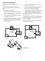
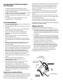
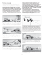
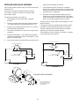
NOTE: The winch must be mounted to angles 9 x 63 x 63
(3/8” x 2-1/2” x 2 1/2” minimum) high strength 344,000 kPa
(50,000 PSI) yield steel angle or in a frame with both sides of
the clutch housing and gear housing bolted to the angles or
frame. See diagram below for recommended mounting dimensions.
Note various thread depths of mounting holes and use
correspondingly different bolt lengths for proper mounting.
Substitution of attaching hardware items) bolts, nuts, or washers)
different from those supplied with your winch mounting kit can
lead to failure causing damage or serious injury. Use a socket head
mounting bolt on side with Spur Gear Housing (see diagram) to
prevent clearance problems. Use SAE grade 5 bolts or better.
Electrical Connections and Operations
For normal self-recovery work, your existing electrical system is
adequate. Your battery must be kept in good condition. A fully
charged battery and proper connections are essential. Run the
vehicle engine during winching operation to keep battery charged.
3/8-16 x 0.50" DEEP THREADS
(EACH SIDE)
USE SOCKET HEAD MTG BOLTS
ON SIDE WITH SPUR GEAR HSG.
3/8-16x1" DEEP
THREADS
(EACH SIDE)
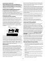
The RAM-LOK® semi-automatic clutch provides free spooling and
clutch engagement with the rope drum. With the clutch disengaged,
the rope can be pulled off the drum by hand. For winching in the
load, the clutch must be fully engaged with the drum.
To disengage the clutch: run the winch in the reverse (“reelout”) direction until the load is off the rope and the rope drum stops
turning. Pull outward on the clutch handle, rotate it counter-clockwise
90º and release. The clutch is now locked out and the rope may be
pulled by hand. (NOTE: If the clutch handle cannot be pulled out,
again run the winch momentarily in reverse to relieve pressure on the
clutch jaws.) WARNING: DO NOT ATTEMPT TO DISENGAGE THE
ROPE DRUM WHEN THERE IS A LOAD ON THE ROPE.
To engage the clutch: pull outward on the handle, rotate it
clockwise 90º and release. Run the winch in reverse until the clutch
handle snaps fully in or until the rope drum starts turning. At this
point make sure the clutch handle is all the way in. The plastic plug
in top of clutch housing may be removed, for inspection of clutch to
assure total engagement. After the clutch is fully engaged, the winch
is ready for winching in the rope.
REMOVE RUBBER COVER FROM
RELIEF FITTINGS BEFORE PUTTING
WINCH INTO USE.
188,8 MM
7.44 IN.
61,2 MM
2.41 IN.
F-2
A
28,5
1.12
3/8-16 x .75"
DEEP THREADS
(EACH SIDE)
63,5 MM
2.50 IN.
MODEL
RE 50,7
RE 50,7X
F-1
A
63,5 MM
2.50 IN.
"A" DIMENSION
IN. ±.015
10.12
13.12
ATTACH BLACK GROUND CABLE
TO THE GROUND TERMINAL
OF THE WINCH MOTOR
mm ±.4
257,2
333,3
Connect black cable from motor ground stud to negative
battery terminal. A good electrical ground is required for proper
performance.
The remote control switch is waterproof and has push button
stations on either side. It is designed this way to prevent quick
winch reversals, which lead to solenoid failure. Make sure the winch
motor has stopped fully before reversing.
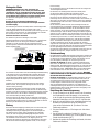
Adjustment of Rated Load Limiter
1. Make some test pulls with winch (using a load cell or
spring scale) to determine if switch is at desired rated
load setting. Acceptable setting is 100% to 125% of
rated load.
2. If load is not within above range, remove tamper-proof
compound in threaded hole (on top of set screws #4).
Remove top set screw.
3. Loosen bottom set screw approximately 2 turns counter
When first setting up your winch, follow the directions for inserting
the proper “IN” or “OUT” label in the thumb button. The switch is
also color coded to aid you in determining the direction your winch
will run.
Maintenance
Check monthly the action of the sliding clutch, making sure it is fully
engaging and disengaging with the rope drum. With the clutch in the
engaged position, remove the plastic plug in top of the housing and
observe if the clutch is fully engaging. If clutch is not fully engaging,
inspect the clutch shifter assembly parts, check for damage or
excessive wear and replace as necessary. Observe the jaws on both
the clutch and rope drum, checking for rounding of the driving faces.
If rounding has occurred they should be replaced immediately.
clockwise.
4. To reduce line pull, thread switch #1 “IN” by turning
clockwise. To increase line pull, thread switch “OUT”.
5. After desired setting is reached, tighten bottom set
5