1
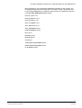
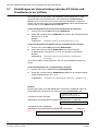
MX Multi-Channel Box
RCI 0601
Benutzerhandbuch
User Manual
Fire Safety & Security Products
Siemens Building Technologies
Liefermöglichkeiten und technische Änderungen vorbehalten.
Data and design subject to change without notice. / Supply subject to availability.
© 2006 Copyright by
Siemens Building Technologies AG
Wir behalten uns alle Rechte an diesem Dokument und an dem in ihm dargestellten Gegenstand vor. Der Empfänger anerkennt diese
Rechte und wird dieses Dokument nicht ohne unsere vorgängige schriftliche Ermächtigung ganz oder teilweise Dritten zugänglich machen
oder außerhalb des Zweckes verwenden, zu dem es ihm übergeben worden ist.
We reserve all rights in this document and in the subject thereof. By acceptance of the document the recipient acknowledges these rights
and undertakes not to publish the document nor the subject thereof in full or in part, nor to make them available to any third party without our
prior express written authorization, nor to use it for any purpose other than for which it was delivered to him.
Inhalt
1
Beschreibung ..........................................................................................5
2
Sicherheit.................................................................................................6
3
3.1
3.2
Richtlinien und Normen .........................................................................7
Elektromagnetische Verträglichkeit (EMV) ...............................................7
Konformitätserklärung des Herstellers......................................................7
4
Technische Daten ...................................................................................8
5
Bestellangaben........................................................................................8
6
6.1
6.2
Systemübersicht .....................................................................................9
SISTORE MX ............................................................................................9
SISTORE MX Pro .....................................................................................9
7
7.1
7.1.1
7.1.2
7.1.3
Montage .................................................................................................10
Kabel anschließen...................................................................................10
Beschreibung der Klemmen....................................................................10
RS232-Schnittstelle (GAA-Schnittstelle).................................................11
RS485-Schnittstelle (MX-Schnittstelle) ...................................................11
8
8.1
8.2
Inbetriebnahme .....................................................................................12
Adresse einstellen...................................................................................13
Baudrate einstellen .................................................................................13
9
Anschluss MX Multi-Channel Box an SISTORE MX und
SISTORE MX Pro ...................................................................................14
Geräte anschließen.................................................................................14
MX Multi-Channel Boxen an SISTORE MX anschließen .......................14
MX Multi-Channel Boxen an SISTORE MX Pro (Black Box)
anschließen.............................................................................................14
Einstellungen in der MX Multi-Channel Box ...........................................15
MX Multi-Channel Box mit der MX-Applikation parametrieren ...............15
Einstellungen in der GAA.ini-Datei..........................................................15
Einstellungen für TYP=SNI .....................................................................16
Einstellungen für TYP=SNI_DREBA.......................................................17
Einstellungen für TYP=NCR ...................................................................17
Einstellungen für weitere GAA-Typen.....................................................17
Informationen zum Telegramm-Ablauf ...................................................18
Einträge STEP-Kennung für Bildaufzeichnung.......................................18
Einstellungen zur Unterscheidung zwischen EC-Karten und
Kreditkarten in der ini-Datei ....................................................................20
Eintrag Timeout-Zeit ...............................................................................21
Eintrag Zähler für den dritten STEP........................................................21
Eintrag für verkettete Vorgänge ..............................................................21
Eintrag parametrierbares Statusflag .......................................................22
Eintrag für die Zeitsynchronisation..........................................................22
Eintrag parametrierbarer STEP für die Zeitsynchronisation ...................22
Eintrag (Workaround) für Fehler in der Sequenznummer des ersten
Telegramms ............................................................................................23
Eintrag STEP, ab dem die Sequenznummer geprüft wird......................23
9.1
9.1.1
9.1.2
9.2
9.3
9.4
9.4.1
9.4.2
9.4.3
9.4.4
9.5
9.6
9.7
9.8
9.9
9.10
9.11
9.12
9.13
9.14
9.15
3
Siemens Building Technologies
Fire Safety & Security Products
06.2006
10
10.1
10.2
10.2.1
10.2.2
10.2.3
Anschluss von GAA an SISTORE MX .................................................24
Schnittstelleneinstellung..........................................................................24
GAA-Telegrammtyp ................................................................................25
Beispiel für Telegramm SNI, SNI_DREBA..............................................25
Beispiel für Telegramm NCR ..................................................................25
Beispiel für Telegramm IBM, IBM_PBM, SNI_PBM ...............................26
11
Instandhaltung ......................................................................................26
12
Entsorgung ............................................................................................26
4
Siemens Building Technologies
Fire Safety & Security Products
06.2006
Beschreibung
1
Beschreibung
Die MX Multi-Channel Box RCI0601 ist für den Anschluss von Geldausgabeautomaten verschiedener Hersteller an den SISTORE MX vorgesehen.
Die MX Multi-Channel Box steuert den Datenverkehr zwischen den
Geldausgabeautomaten und dem SISTORE MX.
Der Einsatz der MX Multi-Channel Box RCI0601 ist nur für den Innenbereich
zugelassen (Schutzklasse IP40).
Zu diesem Handbuch
Dieses Benutzerhandbuch erklärt die Installation und Konfiguration der MX MultiChannel Box.
5
Siemens Building Technologies
Fire Safety & Security Products
06.2006
Sicherheit
2
Sicherheit
Um Schäden zu vermeiden und eine optimale Bildwiedergabe zu erreichen, sollte
diese Betriebsanleitung aufmerksam gelesen und befolgt werden.
Beachten Sie unbedingt folgende Warnhinweise:
z Anschluss, Inbetriebnahme sowie Instandhaltung dürfen nur von entsprechend
qualifiziertem Personal durchgeführt werden.
z Der einwandfreie und sichere Betrieb dieser MX Multi-Channel Box setzt
sachgemäßen Transport, Lagerung und Montage sowie sorgfältige Bedienung
und Instandhaltung voraus.
z Legen Sie keine Gegenstände auf das Gerät. Decken Sie das Gerät nicht ab.
z Bewahren Sie das Gerät vor direkter Sonneneinstrahlung.
z Bringen Sie das Gerät nicht mit Flüssigkeiten jedweder Art in Berührung.
z Bewahren Sie die dieses Dokument zum Nachschlagen auf.
z Geben Sie dieses Dokument auch bei der Weitergabe des Produktes mit.
Wir weisen darauf hin, dass der Inhalt dieser Betriebsanleitung nicht Teil einer früheren oder
bestehenden Vereinbarung, Zusage oder eines Rechtsverhältnisses ist oder dieses abändern soll.
Sämtliche Verpflichtungen von Siemens ergeben sich aus dem jeweiligen Kaufvertrag, der auch die
vollständige und allein gültige Gewährleistungsregelung enthält. Diese vertraglichen
Gewährleistungsbestimmungen werden durch die Ausführung dieser Betriebsanleitung weder
erweitert noch beschränkt.
6
Siemens Building Technologies
Fire Safety & Security Products
06.2006
Richtlinien und Normen
3
Richtlinien und Normen
3.1
Elektromagnetische Verträglichkeit (EMV)
Dieses Produkt ist für den Einsatz in allgemeinen CCTV-Anwendungen in Wohn-,
Geschäfts- oder industriellen Umgebungen ausgelegt. Wenden Sie sich bitte an
den Lieferanten dieses Produktes, bevor Sie es in medizinischen und/oder
eigensicheren Anwendungen oder in einer industriellen EMV-Umgebung
installieren.
Das Produkt muss gemäß den aktuell gültigen Installationsvorschriften für EMV
installiert werden, um den bestimmungsgemäßen Betrieb sicherzustellen und
EMV-Probleme zu verhindern.
3.2
Konformitätserklärung des Herstellers
Das mit dieser Bedienungsanleitung gelieferte Gerät entspricht den Anforderungen
der EG-Richtlinie 89/336/ EWG für elektromagnetische Verträglichkeit.
Dies wurde nachgewiesen durch Prüfung nach den Normen:
Störaussendung:
EN 61000-6-3:2001, EN 55022 Kl. B: 1998
Störfestigkeit:
EN 50130-4 + A1: 1998
Die EG-Konformitätserklärungen werden für die zuständigen Behörden zur
Verfügung gehalten bei:
Siemens Building Technologies
Fire & Security Products GmbH & Co. oHG
Siemensallee 84
76187 Karlsruhe
7
Siemens Building Technologies
Fire Safety & Security Products
06.2006
Technische Daten
4
Technische Daten
Anschlüsse
14 x Federkraftklemme
1x RS232 für GAA
2x RS485 für SISTORE MX
5
Aderquerschnitt
0,08 bis 0,5 mm² bzw. AWG28-20
Dateneingang
GAA-Schnittstelle, Protokoll
parametrierbar
Baudrate
parametrierbar
Datenausgang
RS485
Baudrate
19200 / 38400 / 57600 / 115200 Baud,
umschaltbar
Spannungsversorgung
DC 12 V ± 10 %, max. 150 mA
Gebrauchstemperaturbereich,
relative Luftfeuchtigkeit
0 bis + 50 °C,
5 bis 95 %, nicht kondensierend
Maße (B x H x T) in mm
130 x 180 x 40
(ohne Kabelverschraubung)
Kabeleinführung
1 x M12 x 1,5 für Kabeldurchmesser von
3,5 bis 7 mm
Schutzklasse
IP40
Bestellangaben
Typ
Art.-Nr.
Bezeichnung
Gewicht
RCI0601
S24245-F5092-A1
MX Multi-Channel Box
0,60 kg
Zubehör, nicht im Lieferumfang enthalten
Steckernetzgerät
485 SD9R
2GF1800-8BE
230 V, 50 Hz/DC 12 V, 640 mA,
für Innenräume, mit 2 m DC-Kabel
0,53 kg
Konverter Firma B+B Electronics
8
Siemens Building Technologies
Fire Safety & Security Products
06.2006
Systemübersicht
6
Systemübersicht
6.1
SISTORE MX
Abb. 1
6.2
Systemübersicht SISTORE MX
SISTORE MX Pro
Abb. 2
Systemübersicht SISTORE MX Pro
9
Siemens Building Technologies
Fire Safety & Security Products
06.2006
Montage
7
Montage
Zum Befestigen des Kunststoffgehäuses verwenden Sie
z auf Metall:
vier Schrauben M4 x 16
z auf Holz:
vier Holzschrauben Ø 3,5 x 20
z auf Beton / an Wand: vier Holzschrauben
Ø 3,5 x 40 mit Dübel Ø 5
(Schrauben nicht im Lieferumfang enthalten).
7.1
1.
Öffnen Sie das Gehäuse durch Abschrauben des Deckels.
2.
Führen Sie die Kabel durch diese Kabelverschraubungen in das Gehäuse ein.
3.
Schließen Sie die Kabel an gemäß Abschnitt 7.1: Kabel anschließen.
4.
Stellen Sie die Schiebeschalter ein gemäß Abschnitten 8.1: Adresse
einstellen und 8.2: Baudrate einstellen.
5.
Schließen Sie das Gehäuse durch Anschrauben des Deckels.
Kabel anschließen
1.
Schließen Sie die MX Multi-Channel Box an die Spannungsversorgung an.
Bei Anschluss z. B. an Steckernetzgerät (2GF1800-8BE, nicht im
Lieferumfang) ist auf die richtige Polung zu achten.
7.1.1
2.
Schließen Sie das Kabel an den Klemmen 1, 2 und 3, 4 DC 12 V. Vergleichen
Sie hierzu Tab. 1: Beschreibung der Klemmen.
3.
Schließen Sie die Geldausgabeautomaten an der RS232-Schnittstelle an.
Vergleichen Sie hierzu Kap. 7.1.2: RS232-Schnittstelle (GAA-Schnittstelle)
4.
Schließen Sie den SISTORE MX an der RS485-Schnittstelle an. Vergleichen
Sie hierzu Kap. 7.1.3: RS485-Schnittstelle (MX-Schnittstelle).
Beschreibung der Klemmen
Klemme
Tab. 1
Beschreibung
1
+12 V DC Versorgungsspannung
2
+12 V DC Versorgungsspannung (intern verbunden mit 1)
3
0 V DC Versorgungsspannung Masse
4
0 V DC Versorgungsspannung Masse (intern verbunden mit 3)
5
RS232 TXD
6
RS232 RXD
7
0 V DC (intern verbunden mit 3, 4)
8
RS485 T-
9
RS485 T+
10
0 V DC (intern verbunden mit 3, 4)
11
+ TTY Out
12
- TTY Out
13
0 V DC (intern verbunden mit 3, 4)
14
0 V DC (intern verbunden mit 3, 4)
Beschreibung der Klemmen
10
Siemens Building Technologies
Fire Safety & Security Products
06.2006
Montage
7.1.2
RS232-Schnittstelle (GAA-Schnittstelle)
Abb. 3
9pol. Sub-D-Stecker
Pin 2: RXD
Pin 3: TXD
Pin 5: GND
Die Verbindung zum Geldausgabeautomaten (GAA) kann mittels eines NullModem-Kabels erfolgen.
7.1.3
RS485-Schnittstelle (MX-Schnittstelle)
Abb. 4
9pol. Sub-D-Buchse
Pin 2: Data+
Pin 3: Data Die Verbindung zum SISTORE MX und weiteren MX Multi-Channel Boxen kann
mittels eines 1:1-Kabel (Verlängerungskabel) erfolgen.
11
Siemens Building Technologies
Fire Safety & Security Products
06.2006
Inbetriebnahme
8
Inbetriebnahme
Die MX Multi-Channel Box wird immer nur einem Geldausgabeautomaten
zugeordnet. Zur Unterscheidung muss für jedes Gerät intern eine andere
Adresse vergeben werden. Insgesamt können 8 MX Multi-Channel Boxen in Reihe
angeschlossen werden. Es ist darauf zu achten, dass bei Anschluss von mehreren
MX Multi-Channel Boxen unterschiedliche Adressen in aufsteigender Reihenfolge,
jedoch gleicher Baudrate, eingestellt werden.
Gemäß Spezifikation darf die Leitungslänge des RS485-Busses 1,2 km nicht
überschreiten.
WICHTIG
Eine normgerechte Terminierung der Leitungsenden ist vorzusehen.
Die Einstellung der GAA-Schnittstelle erfolgt automatisch über den SISTORE MX
beim Start des SISTORE MX.
Abb. 5
Innenansicht MX Multi-Channel Box
1
RS485 Busabschluss
2
SW1
3
SW2
12
Siemens Building Technologies
Fire Safety & Security Products
06.2006
Inbetriebnahme
8.1
Adresse einstellen
Stellen Sie die Adresse mit dem 8fach-Schiebeschalter SW1 ein.
Die Schalter S1 bis S4 sind für die Adressierung vorgesehen.
Die Schalter S5 bis S8 werden nicht benutzt (auf ”OFF” stellen).
8fach-Schiebeschalter
SW1
S1-S4
Die Adresse wird binär eingestellt. ”1” bedeutet Schalterstellung auf ”ON”,
”0” bedeutet auf ”OFF”.
Voreinstellung
1000= Adresse 1
0100 = Adresse 2
1100 = Adresse 3
0010 = Adresse 4
1010 = Adresse 5
0110 = Adresse 6
1110 = Adresse 7
0001 = Adresse 8
Adresseinstellungen
Tab. 2
8.2
Baudrate einstellen
Stellen Sie die Baudrate mit dem 8fach-Schiebeschalter SW2 ein.
Die Schalter S3 und S4 sind für die Baudrate zum SISTORE MX vorgesehen.
Die Schalter S1 und S2 sind nicht relevant.
Die Schalter S5 bis S8 müssen immer auf OFF stehen.
ON
OFF
4
1
2
3
5
8fach-Schiebeschalter
Voreinstellung
Tab. 3
6
7
8
SW2
S3
S4
Baudrate
0
0
19200 Baud
1
0
38400 Baud
0
1
57600 Baud
1
1
115200 Baud
SW2: Baudrate SISTORE MX
Alle nicht ausdrücklich erwähnten Schalterstellungen werden nicht unterstützt!
Nach einer Änderung der Schiebeschalter muss die MX Multi-Channel Box durch Aus- und
Wiedereinschalten der Spannungsversorgung neu initialisiert werden!
13
Siemens Building Technologies
Fire Safety & Security Products
06.2006
Anschluss MX Multi-Channel Box an SISTORE MX und SISTORE MX Pro
9
Anschluss MX Multi-Channel Box an SISTORE MX
und SISTORE MX Pro
Für den Anschluss von MX Multi-Channel Box an SISTORE MX und SISTORE MX
Pro gehen Sie wie folgt vor:
9.1
1.
Geräte anschließen. Vergleichen Sie hierzu Kap. 9.1: Geräte anschließen.
2.
MX Multi-Channel Box mit der MX-Applikation parametrieren. Vergleichen Sie
hierzu Kap. 9.3: MX Multi-Channel Box mit der MX-Applikation parametrieren.
3.
Einstellungen in der GAA.ini-Datei vornehmen. Vergleichen Sie hierzu Kap.
9.4: Einstellungen in der GAA.ini-Datei .
Geräte anschließen
Sie können MX Multi-Channel Boxen an
z SISTORE MX oder an
z SISTORE MX Pro (Black Box)
anschließen.
9.1.1
MX Multi-Channel Boxen an SISTORE MX anschließen
Voraussetzung:
Verwenden Sie nur 1-zu-1-Kabel mit verdrahtetem Pin 2 und 3.
Schließen Sie alle MX Multi-Channel Boxen (RS485) in Reihe (physikalisch
parallel) an dem SISTORE MX (COM1/COM2) an. Vergleichen Sie hierzu Kap.
6.1: SISTORE MX.
9.1.2
MX Multi-Channel Boxen an SISTORE MX Pro (Black Box) anschließen
Voraussetzung:
– Für den Anschluss der MX Multi-Channel Box an SISTORE MX Pro (Black
Box) ist ein RS232-RS485-Konverter zu verwenden. Vergleichen Sie hierzu
Kap. 5: Bestellangaben.
– Verwenden Sie das Kabel zwischen MX Multi-Channel Box und Konverter
mit verdrahtetem Pin 2 und 3.
1.
Schließen Sie ein RS232-RS485-Konverter an dem SISTORE MX Pro
(COM1/COM2) an.
2.
Schließen Sie alle MX Multi-Channel Boxen (RS485) in Reihe (physikalisch
parallel) an dem RS232-RS485-Konverter an. Vergleichen Sie hierzu Kap.
6.2: SISTORE MX Pro.
14
Siemens Building Technologies
Fire Safety & Security Products
06.2006
Anschluss MX Multi-Channel Box an SISTORE MX und SISTORE MX Pro
9.2
9.3
9.4
Einstellungen in der MX Multi-Channel Box
1.
Öffnen Sie die MX Multi-Channel Box.
2.
Stellen Sie die Adresse auf DIP Switch 1 ein. Vergleichen Sie hierzu Tab. 2:
Adresseinstellungen.
3.
Stellen Sie Baudrate der RS485-Schnittstelle auf DIP Switch 2, 57 600 Baud.
Vergleichen Sie hierzu Tab. 3: SW2: Baudrate SISTORE MX.
4.
Entfernen Sie in allen Multi-Channel Boxen den RS485-Busabschluss
(schwarze Steckbrücke) mit Ausnahme der letzten Box. Vergleichen Sie
hierzu Abb. 5: Innenansicht MX Multi-Channel Box.
MX Multi-Channel Box mit der MX-Applikation parametrieren
1.
Starten Sie die MX-Applikation.
2.
Wählen Sie aus dem Menü Konfiguration den Menüpunk Bankenmodul.
3.
Tragen Sie den GAA-Typ für jeden verwendeten GAA ein (beim Kunden zu
erfragen).
4.
Geben Sie bis zu 3 GAA-Kameras an, die bei dem jeweiligen GAA
aufgezeichnet werden sollen (es werden nur die Kameras angeboten, die im
Register Kameras als GAA-Kamera definiert sind). Weitere Informationen
hierzu finden Sie im Benutzerhandbuch SISTORE MX.
Einstellungen in der GAA.ini-Datei
HINWEIS
Ab SISTORE MX Version 2.58 kann die Multi-Channel Box mittels der SISTORE MX-Applikation
V2.58 konfiguriert werden.
1.
Öffnen Sie die Datei C:\Program Files\Cevis\Sistore\GAA.ini mit dem
Notepad.
2.
Ergänzen Sie in den jeweiligen Abschnitten folgende Einstellungen:
Abschnitt
Einstellung
[SERVER]
Hier müssen normalerweise keine Korrekturen vorgenommen werden.
[START]
Hier gibt es nur den Eintrag DELAY. Der Defaultwert ist 10 und muss für die
Systeme MX (Kompaktsysteme) nicht verändert werden.
Für die Systeme MX Pro (Black Box) setzen Sie den Wert auf 30.
[DEBUGINFO]
Hier wird festgelegt, ob eine Log-Datei geschrieben wird.
[SS_GAA]
Hier werden die Einstellungen der Schnittstelle MX-Multi-Channel-Box(en) und
SISTORE MX und SISTORE MX Pro definiert .
Behalten Sie die Einstellungen bei.
3.
Nehmen Sie für jeden der 8 möglichen GAA im Block [SS x] (unter der Zeile
[SSx], x = 1 ... 8), abhängig vom GAA-Typ, folgende Einstellungen vor:
– TYP:
Wenn Sie in der MX-Applikation die GAA schon parametriert haben, sollte bei
TYP der richtige GAA-Typ und bei KAMERA die parametrierte(n) Kamera(s)
angezeigt werden.
15
Siemens Building Technologies
Fire Safety & Security Products
06.2006
Anschluss MX Multi-Channel Box an SISTORE MX und SISTORE MX Pro
– FORMAT:
Tragen Sie die Schnittstellenparameter des GAA unter FORMAT ein.
(Weitere Informationen hierzu finden Sie in der GAA-Dokumentation).
– STATUS_ANF, STATUS_ANT und QUITT:
Die Zeilen STATUS_ANF, STATUS_ANT und QUITT sind abhängig vom Typ
des GAA. Am Ende der ini-Datei, im Kommentar-Block „Hinweise für die
Einstellungen“, finden Sie für jeden Typ die passenden Einstellungen (hier
im Beispiel sind die Daten eines SNI bzw. SNI_DREBA GAA aufgeführt).
Beispiel
[SSx]
TYP=
FORMAT=9600,N,8,1
STATUS_ANF=~00
STATUS_ANT=STX,11111111000000,ETX
QUITT=STX,ACK,ETX
KAMERA=
ZEITSYNC_COMNR=1
// legt fest, ob von diesem GAA eine Zeitsynchronisation des SISTORE MX
vorgenommen werden soll, bei 0 findet keine
Synchronisation statt
BILDANZAHL_PRO_STEP=1
// legt fest, wie viele Bilder bei einem
Telegramm aufgenommen werden, wenn
unter KAMERA= nur eine Kamera definiert
wurde (Defaultwert ist 1)
Die folgenden Zeilen definieren Verzögerungszeiten in Sekunden zwischen
Eintreffen des Telegramms und der eigentlichen Bildaufnahme;
VZ_BILD_BILD wird aktiv, wenn bei einem Telegramm mehrere Bilder von
einer Kamera oder jeweils ein Bild von verschiedenen Kameras gemacht
werden.
VZ_PERSON=0
VZ_GELD=0
VZ_RAUM=0
VZ_BILD_BILD=1
4.
9.4.1
Nehmen Sie weitere typabhängige Einstellungen vor, die in den folgenden
Kapiteln beschrieben sind.
Einstellungen für TYP=SNI
SNI_PORTRAET=1
// legt fest, wie viele Porträt-Telegramme erwartet werden
SNI_RAUM=1
// legt fest, wie viele Raum-Telegramme erwartet werden
16
Siemens Building Technologies
Fire Safety & Security Products
06.2006
Anschluss MX Multi-Channel Box an SISTORE MX und SISTORE MX Pro
9.4.2
9.4.3
Einstellungen für TYP=SNI_DREBA
PSTEP=1,3
// beim Telegramm ~01:1 werden die erste und die dritte Kamera der
unter dem Eintrag KAMERA= definierten Kameras (Porträt und Foyer)
aufgezeichnet
PSTEP_1=1,3
// beim Telegramm ~20/21/22: werden die erste und die dritte Kamera der
unter dem Eintrag KAMERA= definierten Kameras (Porträt und Foyer)
aufgezeichnet
PSTEP_2=1,3
// beim Telegramm ~30/31: werden die erste und die dritte Kamera der
unter dem Eintrag KAMERA= definierten Kameras (Porträt und Foyer)
aufgezeichnet
GSTEP=2,2,2
// beim Telegramm ~01:2: wird die zweite Kamera der unter dem Eintrag
KAMERA definierten Kameras (Geldfach) 3-mal aufgezeichnet
GSTEP_1=2,3
// beim Telegramm ~32: werden die zweite und die dritte Kamera der
unter dem Eintrag KAMERA= definierten Kameras (Geldfach und Foyer)
aufgezeichnet
RSTEP=3,3,3
// beim Telegramm ~01:0 wird die dritte Kamera der unter dem Eintrag
KAMERA= definierten Kameras (Foyer) 3-mal aufgezeichnet
Einstellungen für TYP=NCR
NCR_TELEGRAMME=2
9.4.4
// Es kommen 2 Telegramme während einer Transaktion vom NCR - GAA,
Default = 3
Einstellungen für weitere GAA-Typen
Alle weiteren GAA-Typen:
z TYP=IBM
z TYP=IBM_PBM
z TYP=SNI_PBM
z TYP=DIEBOLD
z TYP=KEBA_GAA
z TYP=ASCOM
arbeiten nach dem PBM (Personal Banking Machine) Protokoll von IBM.
Dieses Protokoll erlaubt den Rechenzentren der Banken gewisse Freiheiten in
einem „variablen Feld“ der Telegramme.
Bei verschiedenen Inbetriebnahmen hat sich gezeigt, dass nicht alle GAA genau
nach dem gleichen Datenmuster der Spezifikation arbeiten.
Diese Tatsache erlaubt auf MX-Seite somit keine Standard-Einstellungen, die eine
einfache IBS ermöglichen könnten, d.h. es muss stets nach den Bedingungen vor
Ort eine gezielte Parametrierung der GAA-Einstellungen am MX erfolgen.
Da in vielen Fällen sehr wenig Informationen über die tatsächlichen GAATelegramme beim IBS-Mitarbeiter vorliegen, wurde die Möglichkeit geschaffen, mit
dem MX-System die vom GAA gesendeten Daten aufzuzeichnen. Die Darstellung
der vom GAA gesendeten Telegramme gestattet dann eine gezielte
Parametrierung des SISTORE MX.
17
Siemens Building Technologies
Fire Safety & Security Products
06.2006
Anschluss MX Multi-Channel Box an SISTORE MX und SISTORE MX Pro
9.5
Informationen zum Telegramm-Ablauf
Bei der PBM-Kommunikation werden sogenannte Steuertelegramme mit und ohne
variablem Dateninhalt verwendet. Grundsätzlich sind 3 Telegrammkomponenten
als wichtigstes Merkmal für den Anschluss an SISTORE MX zu sehen:
z die Sequenznummer
z die STEP-Kennung für die Bildsteuerung
z die Daten im variablen Feld (Kontonummer, BLZ, Betrag usw.)
Eine Transaktion wird mit dem Eintreffen einer neuen Sequenznummer
angestoßen. Die Sequenznummer wird aus dem festen Teil des Telegramms
Stelle 22 bis 25 gelesen (“Fixed Field“).
9.6
Einträge STEP-Kennung für Bildaufzeichnung
Die Bildaufzeichnung für Bild 1, 2 (3) wird anhand der STEP-Kennung eingeleitet,
d. h. die STEP-Kennung bestimmt, ob und zu welchem Zeitpunkt ein Bild
aufgezeichnet wird. Die Einstellung, welche STEPs benutzt werden, erfolgt mit drei
in der ini-Datei einstellbaren STEPs. Wenn kein STEP 3 angegeben ist, wird Bild 3
über eine in der Parametrierung einstellbare Verzögerungszeit (VZ_BILD_BILD )
aufgezeichnet, als Folge von Bild 2.
Die STEP-Kennung steht im “Fixed Field“ des Telegramms an Stelle 26 und 27.
STEP1=3
// STEP1: STEP-Nr. für erste Bildaufnahme
STEP2=7
// STEP2: STEP-Nr. für zweite Bildaufnahme
STEP3=11
// STEP3: STEP-Nr. für dritte Bildaufnahme
Achtung:
Damit die GAA-Kopplung einen gesicherten Ablauf garantieren kann, müssen im GAA mindestens
zwei Felder (STEP 3 u. 10 oder 11) freigeschaltet sein !
Die Freischaltung erfolgt direkt am GAA über die “CI”. Es handelt sich hierbei um die
Konfigurationsdatei “Custom.dat”.
Folgende Informationen aus dem Telegramm (fester u. variabler Teil) können
konfiguriert werden:
z Datum: Tag, Monat, Jahr
z Uhrzeit: Stunden, Minuten, Sekunden
z Kontonummer
z Bankleitzahl
z Betrag
z Währung
z Status
z Transaktionsnummer
z Kreditkartennummer
z ID-Nr (Workstation-ID)
18
Siemens Building Technologies
Fire Safety & Security Products
06.2006
Anschluss MX Multi-Channel Box an SISTORE MX und SISTORE MX Pro
Diese entsprechen den nachfolgend aufgelisteten Einträgen in der ini-Datei. Um
die Stellenpositionen aus dem Telegramm zu ermitteln, ist der Log-Mechanismus
im Abschnitt [DEBUGINFO] zu aktivieren. Dann können die Telegramme über die
Log-Datei DTC_GAA.log dargestellt werden.
DATUM_TAG=12-13
DATUM_MONAT=10-11
DATUM_JAHR=14-15
ZEIT_STUNDEN=16-17
ZEIT_MINUTEN=18-19
ZEIT_SEKUNDEN=20-21
KONTONUMMER=29-38
BLZ=42-49
BETRAG=56-61
WAEHRUNG=0
STATUS=0
TRANSAKTIONSNUMMER=66-69
KREDITKARTENNUMMER=29-44
ID_NUMMER=85-89
19
Siemens Building Technologies
Fire Safety & Security Products
06.2006
Anschluss MX Multi-Channel Box an SISTORE MX und SISTORE MX Pro
9.7
Einstellungen zur Unterscheidung zwischen EC-Karten und
Kreditkarten in der ini-Datei
Die Telegramme von EC-Karten und Kreditkarten unterscheiden sich, je nach
GAA-Automaten bzw. Rechenzentren, durch bestimmte charakteristische
Zeichen (z. B. Leerzeichen), die an einer bestimmten Position im Telegramm
stehen und manchmal auch durch die Telegrammlänge. Diese charakteristischen
Zeichen sind an ihrem ASCII-Code identifizierbar.
Unterscheidungskriterium Position des charakteristischen Zeichens
1.
Suchen Sie in der ini-Datei den Eintrag ECKKPOS=.
2.
Geben Sie nach dem Eintrag ECKKPOS= die Position des charakteristischen
Zeichens ein, z. B. 39.
Beispiel:
ECKKPOS=39
// ECKKPOS: Position für die Unterscheidung zw. EC- u. KK
Unterscheidungskriterium ASCII-Code des charakteristischen Zeichens
1.
Suchen Sie in der ini-Datei den Eintrag ECKKCHAR=.
2.
Geben Sie nach dem Eintrag ECKKCHAR= den ASCII-Code des
charakteristischen Zeichens ein, z. B. für ein Leerzeichen die Zahl 32.
Beispiel:
ECKKCHAR=32
// ECKKCHAR: Zeichen für die Unterscheidung, als ASCII-Code
//z.B. Chr(32) = " „
In Ausnahme-Fällen ist das Telegramm, das von einer Kreditkarte erzeugt wird,
länger.
Unterscheidungskriterium „Telegrammlänge“ festlegen
1.
Suchen Sie in der ini-Datei den Eintrag ECKKDIFLEN=.
2.
Geben Sie nach dem Eintrag ECKKDIFLEN= Differenz der Telegrammlänge
beider Kreditkartentypen ein, z. B. 7.
ECKKDIFLEN=7
// Unterschied in der Telegrammlänge, zwischen EC- u. Kreditkarte z. B 7
Beispiel:
Bei EC-Karten steht an der 39. Position ein Leerzeichen. Kreditkarten haben an
dieser Stelle kein Leerzeichen. Ein Leerzeichen hat den ASCII-Code „32“.
Telegramm bei einer EC-Karte:
Leerzeichen an 39. Position
ASCII-Code für Leerzeichen=32
059067661011603105510991707126550105 0009807579 7 10000 ON
Kein Leerzeichen
Telegramm bei einer Kreditkarte:
0660676610116031059599920071591004D0411021285363
10000 ON
Differenz Telegrammlänge EC-Karte und Kreditkarte = 7 Zeichen
20
Siemens Building Technologies
Fire Safety & Security Products
06.2006
Anschluss MX Multi-Channel Box an SISTORE MX und SISTORE MX Pro
9.8
Eintrag Timeout-Zeit
Nach einer eingestellten Timeout-Zeit wird eine aktive Transaktion automatisch
beendet. Dies ist nötig, um Transaktionen, bei denen der letzte angegebene STEP
fehlt, wie zum Beispiel bei einer Kontostandsabfrage, ordnungsgemäß zu
schließen. Die Angabe der Timeout-Zeit erfolgt in Sekunden.
TIMEOUT=300
Wird eine Transaktion durch Timeout beendet, erfolgt ein Archiveintrag mit
Status=2.
9.9
Eintrag Zähler für den dritten STEP
Einige Rechenzentren haben die Kameraschnittstelle des GAA derart ausgelegt,
dass mit dem Telegramm, meistens ist es STEP11, das zum Zeitpunkt der
Geldentnahme gesendet wird, signalisiert wird, ob der Kunde die Banknoten aus
dem Geldfach entnommen hat. Das erste Telegramm mit diesem STEP wird
gesendet, wenn der GAA die Banknoten bereitstellt und das zweite Telegramm
wird gesendet, wenn der Kunde die Banknoten aus dem Geldfach entnimmt.
Vergisst der Kunde die Banknoten zu entnehmen, zieht der GAA die Banknoten
wieder ein, in diesem Fall fehlt dann das zweite Telegramm und im Archiveintrag
wird mit dem Status 1 vermerkt, dass der Kunde das Geld nicht erhalten hat. Wenn
das Geld entnommen wurde, wird der Status auf 0 gesetzt.
STEP3COUNT=1 // Angabe, wie oft der dritte STEP erwartet wird
9.10
Eintrag für verkettete Vorgänge
Von verketteten Vorgängen spricht man, wenn z. B. auf eine Kontostandsabfrage
sofort eine Geldabbuchung erfolgt, ohne dass zwischenzeitlich die EC-Karte
entnommen wird.
Im Rechenzentrum werden die beiden Vorgänge unter zwei aufeinanderfolgenden
Transaktionsnummern geführt.
An der Kameraschnittstelle des GAA ergeben sich folgende
Telegrammkonstellationen: Die Kontostandsabfrage endet z.B. mit dem STEP 6,
dann kommt ein weiteres Telegramm mit dem STEP 6, in dem die
Transaktionsnummer (Sequenznummer) bereits erhöht wurde. Dieses Telegramm
ist der Geldabbuchung zuzuordnen.
Mit dem Eintrag VKSTEP=6 erwartet SISTORE MX bzw. SISTORE MX Pro diese
Telegrammfolge vom GAA und legt alle Bilder des Vorgangs unter einem
Archiveintrag ab.
SIS_NT.INI-File :
VKSTEP=6
//STEP für verkette Transaktionen
21
Siemens Building Technologies
Fire Safety & Security Products
06.2006
Anschluss MX Multi-Channel Box an SISTORE MX und SISTORE MX Pro
9.11
Eintrag parametrierbares Statusflag
Wenn der GAA gestartet wird bzw. in regelmäßigen Zeitabständen, sendet er auf
der Kameraschnittstelle einen Initialisierungsstring, der vom SISTORE MX u.a. mit
dem Statusflag beantwortet werden muss. Stimmt dieses Statusflag nicht mit dem
Statusflag überein, das der GAA erwartet, so schaltet der GAA die
Kameraschnittstelle total ab.
Ältere GAA erwarten als Statusflag 1010 während neuere Automaten mit 0000
arbeiten.
STATUSFLAG=0000
9.12
Eintrag für die Zeitsynchronisation
Werden an ein SISTORE MX-System mehrere GAA angeschlossen, so kann mit
dieser Angabe festgelegt werden, von welchen GAA das SISTORE MX-System
synchronisiert wird.
Es wird empfohlen, die Zeitsynchronisation nur bei einer Schnittstelle zu aktivieren;
falls die GAA untereinander unterschiedliche Zeiten haben, ist dies zwingend
notwendig.
ini-Datei :
ZEITSYNC_COMNR=1 // Zeitsynchronisation wird von dieser Schnittstelle
vorgenommen
9.13
Eintrag parametrierbarer STEP für die Zeitsynchronisation
Datum und Uhrzeit stehen sowohl im Fixed Field als auch im variablen Field, wenn
es eines gibt.
Über die Telegrammkonfiguration in der ini-Datei können die Stellen angegeben
werden, an denen Datum und Uhrzeit erwartet wird. In der Regel gibt es nun bei
einer Transaktion mehrere Telegramme mit relevantem Datum und Uhrzeit; z. B.
wenn diese aus dem Fixed Field entnommen werden, so kann über die
Parametrierung ZEITSTEP festgelegt werden, von welchem Telegramm die
Synchronisation vorgenommen werden soll. Damit soll eine optimale
Übereinstimmung der Uhrzeit zwischen SISTORE MX-Archiv und GAA-Journal
erreicht werden.
ZEITSTEP=11
// STEP, von dem die Zeitsynchronisation vorgenommen
wird
22
Siemens Building Technologies
Fire Safety & Security Products
06.2006
Anschluss MX Multi-Channel Box an SISTORE MX und SISTORE MX Pro
9.14
Eintrag (Workaround) für Fehler in der Sequenznummer des
ersten Telegramms
Normalerweise wird eine neue Transaktion mit dem ersten Telegramm (Porträt)
eingeleitet. In diesem Telegramm sollte die Sequenznummer gegenüber der
vorhergehenden Transaktion um 1 erhöht sein. Einige GAA bzw. Rechenzentren
erhöhen jedoch die Sequenznummer erst beim zweiten Telegramm der
Transaktion (Fehler).
Dieses Problem kann durch die Angabe des STEP, bei dem die Sequenznummer
erhöht wird, umgangen werden, so dass die Porträtaufnahme der neuen
Transaktion zugeordnet wird.
STEPINCSQNR=11
9.15
// STEP, bei dem die Sequenznummer hochgezählt
wird
Eintrag STEP, ab dem die Sequenznummer geprüft wird
Einige GAA bzw. Rechenzentren zählen die Sequenznummer bei
Kontostandsabfragen nicht weiter, d. h. werden mehrere Kontostandsabfragen mit
verschiedenen EC-Karten nacheinander ohne Verfügung durchgeführt, dann
werden diese alle mit der gleiche Sequenznummer gemeldet. Damit von jeder
dieser Kontostandsabfragen auch ein Bild erzeugt wird, ist es erforderlich, den
Test der Sequenznummer auf den dabei gemeldeten STEP zu setzen.
STEPTESTSQNR=3
// STEP, ab dem die Sequenznummer geprüft wird
23
Siemens Building Technologies
Fire Safety & Security Products
06.2006
Anschluss von GAA an SISTORE MX
10
Anschluss von GAA an SISTORE MX
Voraussetzung:
Zum Anschluss an SISTORE benötigen Sie für jeden GAA eine MX MultiChannel Box.
Beim Anschluss von GAA an SISTORE MX gehen Sie wie folgt vor:
3.
Informieren Sie sich über die Schnittstelleneinstellung beim Hersteller des
GAA oder beim Kunden.
Schnittstelleneinstellung: Baudrate, Daten/Stop/Parity-Bit(s).
4.
Wenn keine Infos über den GAA-Schnittstelle vorliegen, untersuchen Sie die
Schnittstelle mit Hilfe des Log-Mechanismus.
– Öffnen Sie die ini-Datei.
– Prüfen Sie unter Format (vgl. Kap. 9.4) die unterschiedlichen
Schnittstellenparameter. Vergleichen Sie hierzu Kap. 10.1:
Schnittstelleneinstellung.
– Tragen Sie den richtigen GAA-Typ ein. Wenn kein Typ eingetragen ist, wird
die Schnittstelle nicht berücksichtigt.
10.1
Schnittstelleneinstellung
Folgende Schnittstelleneinstellung werden am häufigsten verwendet:
Bei SNI-GAA: (für SNI, SNI_DREBA und SNI_PBM)
2400 Baud, 8 D-Bits, 1 Stop-Bit, None-Parity
9600 Baud, 8 D-Bits, 1 Stop-Bit, None-Parity
Bei IBM- bzw. NCR-GAA
1200 Baud, 7 D-Bits, 1 Stop-Bit, Odd-Parity
9600 Baud, 8 D-Bits, 1 Stop-Bit, None-Parity
Bei ASCOM-GAA
9600 Baud, 7 D-Bits, 1 Stop-Bit, Odd-Parity
24
Siemens Building Technologies
Fire Safety & Security Products
06.2006
Anschluss von GAA an SISTORE MX
10.2
GAA-Telegrammtyp
Es gibt drei GAA-Telegrammtypen, die Ihnen zur Verfügung stehen:
z SNI. Vergleichen Sie hierzu Kap. 10.2.1: Beispiel für Telegramm SNI,
SNI_DREBA.
z NCR. Vergleichen Sie hierzu Kap. 10.2.2: Beispiel für Telegramm NCR.
z IBM. Vergleichen Sie hierzu Kap. 10.2.3: Beispiel für Telegramm IBM,
IBM_PBM, SNI_PBM.
Hier sind die möglichen Steuerzeichen, die in den Telegrammen vorkommen
können:
z ASCII Dezimal 2
(STX)
z ASCII Dezimal 3
(ETX)
z ASCII Dezimal 6
(ACK)
z ASCII Dezimal 10
(LF)
z ASCII Dezimal 13
(CR)
z ASCII Dezimal 31
(US)
Diese Steuerzeichen werden in der Log-Datei entweder als Leerzeichen, dicker
schwarzer senkrechter Strich oder nicht ausgefülltes Karo dargestellt. Außer im
NCR-Telegramm kommen diese jedoch nur am Anfang und Ende eines
Telegramms vor. Bei NCR wird das US als Trennzeichen zwischen den InfoBlöcken verwendet.
10.2.1 Beispiel für Telegramm SNI, SNI_DREBA
STX03500~00:00~10:991130~11:122919~12:001ETX
Merkmale:
z Trennung der Felder durch „~“
z Feldnummer, z.B. „~10:“ für Datum
10.2.2 Beispiel für Telegramm NCR
STX5290US424010US948USUS10005752US7162544610ETX
Merkmale:
z Trennung der Felder durch „US“
z Alle Felder werden von rechts beginnend gelesen
z Erstes Feld Zeit, nur 4-stellig,z. B. 5290, entspricht 09:25
z Zweites Feld Datum, z.B. 424010, entspricht 24.04.01
z Drittes Feld TSA-Nr., z.B. 948, entspricht 849
z Viertes Feld BLZ, z.B. 10005752, entspricht 257 500 01
z Fünftes Feld Konto Nr., z.B. 7162544610, entspricht 0164452617
25
Siemens Building Technologies
Fire Safety & Security Products
06.2006
Instandhaltung
10.2.3
Beispiel für Telegramm IBM, IBM_PBM, SNI_PBM
STX0280999991130991231310007111ETX
Merkmale:
z 28 Stellen (Fixed Field) ohne Trennzeichen
z STX08901608108260215222572040710005757232 1 76351040 0312
000100,00 7204 020826 152225 16081ETX
z Im variablen Feld können auch Blanks vorkommen.
z Der Telegrammaufbau bei IBM ist immer gleich, die ersten 3 Stellen nach dem
STX geben die Gesamtlänge des Telegramms an, inklusiv der Blanks, aber
ohne ETX.
11
Instandhaltung
Eine defekte MX Multi-Channel Box sollte an das SIEMENS Service Center Berlin
gesendet werden.
12
Entsorgung
Alle Elektro- und Elektronikgeräte sind getrennt vom allgemeinen Hausmüll über
dafür staatlich vorgesehene Stellen zu entsorgen.
Wenn dieses Symbol eines durchgestrichenen Abfalleimers auf einem Produkt
angebracht ist, unterliegt dieses Produkt der europäischen Richtlinie 2002/96/EC.
Die sachgemäße Entsorgung und getrennte Sammlung von Altgeräten dienen der
Vorbeugung von potenziellen Umwelt- und Gesundheitsschäden. Sie sind eine
Voraussetzung für die Wiederverwendung und das Recycling gebrauchter Elektround Elektronikgeräte. Ausführlichere Informationen zur Entsorgung Ihrer Altgeräte
erhalten Sie bei Ihrer Kommune, Ihrem Müllentsorgungsdienst oder dem Fachhändler,
bei dem Sie das Produkt erworben haben.
26
Siemens Building Technologies
Fire Safety & Security Products
06.2006
MX Multi-Channel Box
RCI 0601
User Manual
Fire Safety & Security Products
Siemens Building Technologies
Liefermöglichkeiten und technische Änderungen vorbehalten.
Data and design subject to change without notice. / Supply subject to availability.
© 2006 Copyright by
Siemens Building Technologies AG
Wir behalten uns alle Rechte an diesem Dokument und an dem in ihm dargestellten Gegenstand vor. Der Empfänger anerkennt diese
Rechte und wird dieses Dokument nicht ohne unsere vorgängige schriftliche Ermächtigung ganz oder teilweise Dritten zugänglich machen
oder außerhalb des Zweckes verwenden, zu dem es ihm übergeben worden ist.
We reserve all rights in this document and in the subject thereof. By acceptance of the document the recipient acknowledges these rights
and undertakes not to publish the document nor the subject thereof in full or in part, nor to make them available to any third party without our
prior express written authorization, nor to use it for any purpose other than for which it was delivered to him
Contents
1
Description ............................................................................................31
2
Safety .....................................................................................................32
3
3.1
3.2
Standards and guidelines ....................................................................33
Electromagnetic compatibility (EMC) ......................................................33
Manufacturer's declaration of conformity ................................................33
4
Technical data .......................................................................................34
5
Details for ordering ...............................................................................34
6
6.1
6.2
System overview ...................................................................................35
SISTORE MX ..........................................................................................35
SISTORE MX Pro ...................................................................................35
7
7.1
7.1.1
7.1.2
7.1.3
Installation .............................................................................................36
Cable connection ....................................................................................36
Terminal assignment...............................................................................36
RS232 interface (cash dispenser interface)............................................37
RS485 interface (MX interface)...............................................................37
8
8.1
8.2
Setup ......................................................................................................38
Address ...................................................................................................39
Baud rate.................................................................................................39
9
9.2
9.3
9.4
9.4.1
9.4.2
9.4.3
9.4.4
9.5
9.6
9.7
9.8
9.9
9.10
9.11
9.12
9.13
9.14
9.15
Connection of MX Multi-Channel Box to SISTORE MX and
SISTORE MX Pro ...................................................................................40
Connecting the devices...........................................................................40
Connecting MX Multi-Channel Boxes to SISTORE MX..........................40
Connecting MX Multi-Channel Boxes to SISTORE MX Pro (Black
Box).........................................................................................................40
Settings in the MX Multi-Channel Box ....................................................41
Configuring the MX application for the MX Multi-Channel Box...............41
Configuring settings in the GAA.ini file....................................................41
Configurations for TYP=SNI....................................................................42
Configurations for TYP=SNI_DREBA .....................................................43
Configurations for TYP=NCR..................................................................43
Configurations for other cash dispenser types .......................................43
Information on the telegram run..............................................................44
STEP ID for picture recording .................................................................44
Distinction between debit cards and credit cards in the .ini file ..............46
Timeout ...................................................................................................47
Counter for the third STEP......................................................................47
Linked transactions .................................................................................47
Configurable status flag ..........................................................................48
Time synchronization ..............................................................................48
Configurable STEP for time synchronization ..........................................48
Workaround for errors in the sequence number of the first telegram .....49
STEP in which the sequence number is checked...................................49
10
10.1
10.2
10.2.1
10.2.2
10.2.3
Connecting cash dispensers to SISTORE MX ...................................50
Interface configuration ............................................................................50
CDM telegram type .................................................................................51
Example of an SNI, SNI_DREBA telegram ............................................51
Example of an NCR telegram .................................................................51
Example of an IBM, IBM_PBM, SNI_PBM telegram ..............................52
9.1
9.1.1
9.1.2
29
Siemens Building Technologies
Fire Safety & Security Products
06.2006
11
Maintenance...........................................................................................52
12
Disposal .................................................................................................52
30
Siemens Building Technologies
Fire Safety & Security Products
06.2006
Description
1
Description
The MX Multi-Channel Box RCI0601 is used to connect cash dispensers from
different manufacturers to SISTORE MX.
The MX Multi-Channel Box controls the data traffic between the cash dispensers
and SISTORE MX.
The MX Multi-Channel Box RCI0601 is designed for indoor use only (protection
class IP40).
About this manual
This user manual provides information on the installation and configuration of the
MX Multi-Channel Box.
31
Siemens Building Technologies
Fire Safety & Security Products
06.2006
Safety
2
Safety
To prevent damage, and to achieve optimum reproduction of images, please read
and follow these operating instructions carefully.
Please mind the following safety information:
z Connection, commissioning and maintenance must only be carried out by
suitably qualified personnel.
z Correct and safe operation of this MX Multi-Channel Box is dependent on proper
transport, storage, installation and connection, as well as careful operation and
maintenance.
z Do not place any objects on top of the device. Do not cover the device.
z Do not place the device in direct sunlight.
z Do not allow the device to come in contact with fluids of any kind.
z Keep this information nearby for reference.
z Always pass this document on together with the product.
Your attention is drawn to the fact that the contents of these operating instructions are not part of a
previous or existing agreement, commitment or statutory right and do not change the latter. All
commitments on the part of Siemens are contained in the respective sales contract which also
contains the complete and solely applicable warranty conditions. These warranty conditions in the
contract are neither extended nor limited by the contents of these operating instructions.
32
Siemens Building Technologies
Fire Safety & Security Products
06.2006
Standards and guidelines
3
Standards and guidelines
3.1
Electromagnetic compatibility (EMC)
This product is designed for use in general CCTV applications in living, business or
industrial environments. Please contact the supplier of this product if you intend to
use it in medical and/or intrinsically safe installations or in an industrial EMC
environment.
The device must be installed according to the currently valid installation regulations
to guarantee the designed use and to prevent EMC problems.
3.2
Manufacturer's declaration of conformity
The device supplied with these operating instructions complies with the EMC
requirements of the EU directive 89/336/ EEC.
This has been proven by testing according to the standards:
Emitted interference:
EN 61000-6-3:2001, EN 55022 Class B: 1998
Interference
resistance:
EN 50130-4 + A1: 1998
The EU declarations of conformity are available to the responsible agencies at
Siemens Building Technologies
Fire & Security Products GmbH & Co. oHG
Siemensallee 84
76187 Karlsruhe
33
Siemens Building Technologies
Fire Safety & Security Products
06.2006
Technical data
4
Technical data
Connections
14 x spring terminal
1x RS232 for ATM
2x RS485 for SISTORE MX
5
Wire cross-section
0.08 to 0.5 mm², or AWG28-20
Data input
CDM interface, configurable protocol
Baud rate
configurable
Data output
RS485
Baud rate
19200 / 38400 / 57600 / 115200 baud,
selectable
Power supply
DC 12 V ± 10 %, max. 150 mA
Operating temperature,
relative humidity
0 to + 50°C,
5 to 95 %, no condensation
Dimensions (W x H x D) in mm
130 x 180 x 40
(without cable glands)
Cable inlet
1 x M12 x 1.5 for cable dia. between 3.5
and 7 mm
Protection class
IP40
Details for ordering
Type
Order No.
Designation
Weight
RCI0601
S24245-F5092-A1
MX multi-channel box
0.60 kg
Accessories, not included in delivery!
Plug-in
power
supply
485 SD9R
2GE1800-8BE
230 V, 50 Hz/DC 12 V, 640 mA,
for indoor use, with 2 m DC cable
0.53 kg
Converter, manufacturer: B+B
Electronics
34
Siemens Building Technologies
Fire Safety & Security Products
06.2006
System overview
6
System overview
6.1
SISTORE MX
Abb. 6
6.2
Functional diagram SISTORE MX
SISTORE MX Pro
Abb. 7
Functional diagram SISTORE MX Pro
35
Siemens Building Technologies
Fire Safety & Security Products
06.2006
Installation
7
Installation
Use the following screw types for mounting the plastic housing
z on metal surfaces:
four screws M4 x 16
z on wooden surfaces:
four wood screws Ø 3.5 x 20
z on concrete / walls:
four wood screws
Ø 3.5 x 40 with plug Ø 5
(screws are not included in the scope of supply).
7.1
1.
Remove the cover to open the housing.
2.
Lead the cables in through these cable glands.
3.
Connect the cables as described in Section 7.1: Kabel anschließen.
4.
Set the dip switches as described in Sections 8.1: Adresse einstellen and 8.2:
Baudrate einstellen.
5.
Replace the cover to close the housing.
Cable connection
1.
Connect the MX Multi-Channel Box to the power source.
When connecting the device to a plug-in power supply (2GF1800-8BE, not
included in the delivery) make sure the polarity is correct.
7.1.1
2.
Connect the cable to the terminals 1, 2 and 3, 4 DC 12 V. See Tab. 1:
Beschreibung der Klemmen.
3.
Connect the cash dispensers via the RS232 interface. See Section 7.1.2:
RS232-Schnittstelle (GAA-Schnittstelle).
4.
Connect the SISTORE MX via the RS485 interface. See Section 7.1.3:
RS485-Schnittstelle (MX-Schnittstelle).
Terminal assignment
Terminal
Tab. 4
Description
1
+12 V DC supply voltage
2
+12 V DC supply voltage (internally connected to terminal 1)
3
0 V DC supply voltage ground
4
0 V DC supply voltage ground (internally connected to terminal 3)
5
RS232 TXD
6
RS232 RXD
7
0 V DC (internally connected to 3, 4)
8
RS485 T-
9
RS485 T+
10
0 V DC (internally connected to 3, 4)
11
+ TTY Out
12
TTY Out
13
0 V DC (internally connected to 3, 4)
14
0 V DC (internally connected to 3, 4)
Terminal assignment
36
Siemens Building Technologies
Fire Safety & Security Products
06.2006
Installation
7.1.2
RS232 interface (cash dispenser interface)
Abb. 8
9-pin Sub-D connector
PIN 2: RXD
PIN 3: TXD
PIN 5: GND
The connection to the cash dispenser can be made using a null-modem cable.
7.1.3
RS485 interface (MX interface)
Abb. 9
9-pin Sub-D socket
PIN 2: Data+
PIN 3: Data The connection to SISTORE MX and to other MX Multi-Channel Boxes can be
made using a 1:1 cable (extension cable).
37
Siemens Building Technologies
Fire Safety & Security Products
06.2006
Setup
8
Setup
The MX Multi-Channel Box is always assigned to only one cash dispenser. For
identification purposes, each device must be assigned its own address. Up to 8
MX Multi-Channel Boxes can be connected in series. If several Multi-Channel
Boxes are connected, make sure that the different addresses have the same baud
rate and are set in ascending order.
IMPORTANT
In accordance with the specification, the line length of the RS485 bus must not
exceed 1.2 km.
The line ends must be terminated conforming to standards.
The cash dispenser interface is set up automatically when SISTORE MX is started.
Abb. 10
Interior view of the MX Multi-Channel Box
1
RS485 bus termination
2
SW1
3
SW2
38
Siemens Building Technologies
Fire Safety & Security Products
06.2006
Setup
8.1
Address
The address is set using switch elements S1 to S4 of the DIP switch SW1.
The switch elements S5 to S8 are not used (must be set to ”OFF”).
8-way dip switch
SW1
S1-S4
The address is set using binary code. ”1” means the switch is in ”ON”
position, ”0” means ”OFF” position.
Default setting
1000= address 1
0100= address 2
1100= address 3
0010= address 4
1010= address 5
0110= address 6
1110= address 7
0001= address 8
Address configuration
Tab. 5
8.2
Baud rate
The baud rate is set using dip switch SW2.
The baud rate to SISTORE MX is set using switch elements S3 and S4.
The switch elements S1 and S2 are not relevant.
The switch elements S5 to S8 must always be set to "OFF".
ON
OFF
4
1
2
8-way dip switch
Default setting
Tab. 6
3
5
6
7
8
SW2
S3
S4
Baud rate
0
0
19200 baud
1
0
38400 baud
0
1
57600 baud
1
1
115200 baud
SW2: Baud rate of SISTORE MX
Switch positions that are not expressly mentioned are not supported!
Whenever the position of the dip switches is changed, the MX Multi-Channel Box must be reinitialized
by power off/power on.
39
Siemens Building Technologies
Fire Safety & Security Products
06.2006
Connection of MX Multi-Channel Box to SISTORE MX and SISTORE MX Pro
9
Connection of MX Multi-Channel Box to SISTORE
MX and SISTORE MX Pro
To connect the MX Multi-Channel Box to SISTORE MX and SISTORE MX Pro,
proceed as follows:
9.1
1.
Connect the devices. See Section 9.1: Geräte anschließen.
2.
Configure the MX application for the MX Multi-Channel Box. See Section 9.3:
MX Multi-Channel Box mit der MX-Applikation parametrieren.
3.
Configure settings in the GAA.ini file. See Section 9.4: Einstellungen in der
GAA.ini-Datei .
Connecting the devices
MX Multi-Channel Boxes can be connected to:
z SISTORE MX or to
z SISTORE MX Pro (Black Box).
9.1.1
Connecting MX Multi-Channel Boxes to SISTORE MX
Prerequisite:
Use only a 1 to 1 cable with pins 2 and 3 wired.
Connect all MX Multi-Channel Boxes (RS485) in series (physically parallel) to the
SISTORE MX (COM1/COM2). See Section 6.1: SISTORE MX.
9.1.2
Connecting MX Multi-Channel Boxes to SISTORE MX Pro (Black Box)
Prerequisite:
– When connecting the MX Multi-Channel Box to SISTORE MX Pro (black
box), an RS232 to RS485 converter has to be used. See Section 5: Details
for ordering.
– Use a cable that has pins 2 and 3 wired between the MX Multi-Channel
Box and the converter.
4.
Connect an RS232 to RS485 converter to the SISTORE MX Pro
(COM1/COM2).
5.
Connect all MX Multi-Channel Boxes (RS485) in series (physically parallel) to
the RS232 to RS485 converter. See Section 6.2: SISTORE MX Pro.
40
Siemens Building Technologies
Fire Safety & Security Products
06.2006
Connection of MX Multi-Channel Box to SISTORE MX and SISTORE MX Pro
9.2
9.3
9.4
Settings in the MX Multi-Channel Box
1.
Open the MX Multi-Channel Box.
2.
Set the address using DIP switch 1. See Tab. 2: Adresseinstellungen.
3.
Set the baud rate of the RS485 interface to 57 600 baud using DIP Switch
2.See Tab. 3: SW2: Baudrate SISTORE MX.
4.
Remove the RS485 bus termination (black jumper) in all Multi-Channel Boxes,
except for the last box. See Abb. 5: Innenansicht MX Multi-Channel Box.
Configuring the MX application for the MX Multi-Channel Box
1.
Start the MX application.
2.
Select Banking in the Configuration menu.
3.
Enter the CDM type of each cash dispenser used (please ask your customer).
4.
You can select up to 3 cameras for each cash dispenser that are to be
recorded (the cameras must have been defined as CDM cameras in the
Cameras tab). Further information on this can be found in the SISTORE MX
User Manual .
Configuring settings in the GAA.ini file
NOTE
From SISTORE MX Version 2.58, the Multi-Channel Box can be configured using the SISTORE MX
application V2.58.
1.
Open the file C:\Program Files\Cevis\Sistore\GAA.ini using Notepad.
2.
Configure the following settings:
Block
Configurations
[SERVER]
It is normally not necessary to make any corrections here.
[START]
The only entry in this section is DELAY. The default value is 10. For MX (compact
systems), this value needs not to be changed.
For MX Pro systems (black box), it must be set to 30.
[DEBUGINFO]
Here you can define whether data will be written to a log file.
[SS_GAA]
The interfaces between the MX Multi-Channel Box(es) and SISTORE MX and
SISTORE MX Pro are configured here.
These settings should not be changed.
3.
Configure the following settings in block [SS x] (below the row [SSx],
x = 1 ... 8) for each of the 8 CDMs, depending on the cash dispenser type:
– TYP:
If you have already configured the cash dispensers in the MX application, the
correct CDM type should be displayed after TYP and the camera(s) you have
configured should be displayed after KAMERA.
– FORMAT:
Enter the interface parameters of the cash dispenser after FORMAT. (More
information on this can be found in the documentation supplied with the cash
dispenser).
– STATUS_ANF, STATUS_ANT and QUITT:
The rows STATUS_ANF, STATUS_ANT and QUITT are dependent on the
41
Siemens Building Technologies
Fire Safety & Security Products
06.2006
Connection of MX Multi-Channel Box to SISTORE MX and SISTORE MX Pro
cash dispenser type. The appropriate configurations for the individual types
(the example shows the settings for an SNI or SNI_DREBA cash dispenser)
are listed in the comments block „Hinweise für die Einstellungen“ at the
end of the .ini file.
Example:
[SSx]
TYP=
FORMAT=9600,N,8,1
STATUS_ANF=~00
STATUS_ANT=STX,11111111000000,ETX
QUITT=STX,ACK,ETX
KAMERA=
ZEITSYNC_COMNR=1
// here you can define whether the CDM will
be time-synchronized with the SISTORE MX;
if "0" is entered, there will be no
synchronization
BILDANZAHL_PRO_STEP=1
// here you can define the number of pictures
to be recorded per telegram if only one
camera is defined for KAMERA= (default
value = 1)
The following parameters define the delay in seconds between the arrival of
the telegram and the start of the recording; VZ_BILD_BILD is active if several
pictures of a single camera or one picture each of different cameras are to be
recorded.
VZ_PERSON=0
VZ_GELD=0
VZ_RAUM=0
VZ_BILD_BILD=1
4.
9.4.1
Further type-dependent configurations are described in the following sections.
Configurations for TYP=SNI
SNI_PORTRAET=1
// here you can define the number of telegrams after which a portrait
picture is taken
SNI_RAUM=1
// here you can define the number of telegrams after which a picture of the
room is taken
42
Siemens Building Technologies
Fire Safety & Security Products
06.2006
Connection of MX Multi-Channel Box to SISTORE MX and SISTORE MX Pro
9.4.2
9.4.3
Configurations for TYP=SNI_DREBA
PSTEP=1,3
// telegram type ~01:1: the pictures of the first and the third camera
specified under KAMERA= (portrait und foyer) will be recorded
PSTEP_1=1,3
// telegram type ~20/21/22: the pictures of the first and the third camera
specified under KAMERA= (portrait und foyer) will be recorded
PSTEP_2=1,3
// telegram type ~30/31: the pictures of the first and the third camera
specified under KAMERA= (portrait und foyer) will be recorded
GSTEP=2,2,2
// telegram type ~01:2: 3 pictures taken by the second camera specified
under KAMERA= (cash drawer) will be recorded
GSTEP_1=2,3
// telegram type ~32: the pictures of the second and the third camera
specified under KAMERA= (cash drawer and foyer) will be recorded
RSTEP=3,3,3
// telegram type ~01:0: 3 pictures taken by the third camera specified
under KAMERA= (foyer) will be recorded
Configurations for TYP=NCR
NCR_TELEGRAMME=2
9.4.4
// 2 telegrams will be sent by the NCR CDM during a transaction; default
value = 3
Configurations for other cash dispenser types
All other cash dispenser types:
z TYP=IBM
z TYP=IBM_PBM
z TYP=SNI_PBM
z TYP=DIEBOLD
z TYP=KEBA_GAA
z TYP=ASCOM
use the PBM (Personal Banking Machine) protocol from IBM.
This protocol allows the banks' computing centres a certain freedom of
configuration in the variable fields of the telegrams.
Experience has shown that not all cash dispensers strictly adhere to the data
pattern of the specification.
It is thus not possible to make standard configurations on the SISTORE MX that
would facilitate installation and setup. These configurations therefore have to be
made on the site individually for each cash dispenser.
The commissioning staff usually has very little information on the individual cash
dispenser telegrams. SISTORE MX therefore allows the data transmitted with the
CDM telegrams to be recorded and visualized. Configuration of the SISTORE MX
is thereby facilitated considerably.
43
Siemens Building Technologies
Fire Safety & Security Products
06.2006
Connection of MX Multi-Channel Box to SISTORE MX and SISTORE MX Pro
9.5
Information on the telegram run
The PBM communication principle uses so-called control telegrams either with or
without variable fields. Basically, there are 3 major telegram components:
z the sequence number
z the step ID for camera control
z the data in the variable field (account number, bank sorting code, amount, etc.)
A transaction is initiated when a new sequence number is received. The sequence
number is read from positions 22 to 25 in the fixed field of the telegram.
9.6
STEP ID for picture recording
The STEP ID defines whether and when a picture will be recorded (pictures 1, 2
(3)). The steps are configured in the .ini file. If STEP 3 has not been defined,
picture no. 3 will be recorded after a preset delay (VZ_BILD_BILD ) as a sequential
picture of picture no. 2.
The STEP ID is contained in the fixed field of the telegram (positions 26 and 27).
STEP1=3
// STEP1: STEP ID for the first picture
STEP2=7
// STEP2: STEP ID for the second picture
STEP3=11
// STEP3: STEP ID for the third picture
Important:
To ensure a reliable operation of the system, at least two fields must have been enabled in the CDM
(STEPs 3 and 10 or 11) !
Enabling is performed directly on the CDM via the “CI”. This is the configuration file “Custom.dat”.
The positions of the following information content of a telegram (fixed and variable
fields) can be configured:
z Date: day, month, year
z Time: hours, minutes, seconds
z Account number
z Bank sort code
z Amount
z Currency
z Status
z Transaction number
z Credit card number
z ID No. (workstation ID)
44
Siemens Building Technologies
Fire Safety & Security Products
06.2006
Connection of MX Multi-Channel Box to SISTORE MX and SISTORE MX Pro
This information corresponds with the entries in the .ini file which are listed below.
To determine the positions in the telegram, the logging mechanism in the block
[DEBUGINFO] must be activated. The telegrams can then be visualized in the log
file DTC_GAA.log.
DATUM_TAG=12-13
DATUM_MONAT=10-11
DATUM_JAHR=14-15
ZEIT_STUNDEN=16-17
ZEIT_MINUTEN=18-19
ZEIT_SEKUNDEN=20-21
KONTONUMMER=29-38
BLZ=42-49
BETRAG=56-61
WAEHRUNG=0
STATUS=0
TRANSAKTIONSNUMMER=66-69
KREDITKARTENNUMMER=29-44
ID_NUMMER=85-89
45
Siemens Building Technologies
Fire Safety & Security Products
06.2006
Connection of MX Multi-Channel Box to SISTORE MX and SISTORE MX Pro
9.7
Distinction between debit cards and credit cards in the .ini file
The telegrams generated by debit cards and credit cards differ in certain typical
characters (e.g. space characters) at specific positions of the telegram and
sometimes also in the telegram length, depending on the cash dispenser type and
the computing centre. These typical characters can be identified by their ASCII
codes.
Distinctive feature: Position of the typical character
1.
Search the .ini file for the entry ECKKPOS=.
2.
Enter the position of the typical character, e.g. 39, after ECKKPOS=.
Example:
ECKKPOS=39
// ECKKPOS: Position of the feature that distinguishes between debit card
and credit card
Distinctive feature: ASCII code of the typical character
3.
Search the .ini file for the entry ECKKCHAR=.
4.
Enter the ASCII code of the typical character after ECKKCHAR=, e.g. the
figure 32 for a space character.
Example:
ECKKCHAR=32
// ECKKCHAR: Character for the distinction as an ASCII code
//e.g. Chr(32) = " „
In some cases, the telegrams generated by credit cards are longer.
Distinctive feature: „Telegram length“
5.
Search the .ini file for the entry ECKKDIFLEN=.
6.
Enter the difference in the telegram length of the two card types after
ECKKDIFLEN=, e.g. 7.
ECKKDIFLEN=7
// Difference in the telegram length between debit and credit card, e.g. 7
Example:
The telegrams of debit cards have a space character at position 39.The telegrams
of credit cards never have a space character at that position. A space character
has ASCII code „32“.
Space character at position 39
ASCII code for space character=32
Telegram generated by a debit card:
059067661011603105510991707126550105 0009807579 7 10000 ON
No space character
Telegram generated by a credit card:
0660676610116031059599920071591004D0411021285363
10000 ON
Difference in telegram length between debit card and credit card = 7
characters
46
Siemens Building Technologies
Fire Safety & Security Products
06.2006
Connection of MX Multi-Channel Box to SISTORE MX and SISTORE MX Pro
9.8
Timeout
An active transaction is terminated automatically after a preset time. This is
necessary in order that transactions for which no last step has been defined, such
as for instance an account balance query, are terminated correctly. The timeout is
indicated in seconds.
TIMEOUT=300
If a transaction is terminated by a timeout, an archive entry "Status=2" is made.
9.9
Counter for the third STEP
In some cases the camera interface of the cash dispenser is configured such that a
telegram - usually STEP11 - is sent when the customer has taken the money from
the slot. The first telegram of this STEP is sent when the money is delivered
through the machine slot, and the second telegram is sent when the customer
takes the money from the slot. If the customer fails to retrieve the money, the cash
dispenser retracts the banknotes left in the output slot. In that case, the second
telegram is not sent and an archive entry is made (status=1) indicating that the
customer did not receive the money. If the money is retrieved, the status is set to
"0".
STEP3COUNT=1 // indicates how many times STEP 3 is expected
9.10
Linked transactions
We speak about a linked transaction when, for instance, a customer withdraws
money immediately after querying his account balance without withdrawing his
debit card.
At the computing centre, the two transactions are registered with successive
transaction numbers.
The following telegrams will be sent over the camera interface of the cash
dispenser: The account balance query is terminated by STEP 6; then another
STEP 6 telegram is sent in which the transaction number (sequence number) is
already incremented. This telegram is allocated to the cash withdrawal.
If the entry in the .ini file is VKSTEP=6, then SISTORE MX or SISTORE MX Pro
expects this telegram sequence from the cash dispenser; all images related to this
process will be saved to the archive.
SIS_NT.INI-File :
VKSTEP=6
//STEP for linked transactions
47
Siemens Building Technologies
Fire Safety & Security Products
06.2006
Connection of MX Multi-Channel Box to SISTORE MX and SISTORE MX Pro
9.11
Configurable status flag
Each time a cash dispenser is started an initialization string is sent over the
camera interface which has to be acknowledged by a status flag sent by SISTORE
MX. If this status flag does not correspond with the status flag the cash dispenser
expects, then the cash dispenser will completely deactivate the camera interface.
Older CDMs use the status flag 1010 while newer models use 0000.
STATUSFLAG=0000
9.12
Time synchronization
If several cash dispensers are connected to one SISTORE MX system, this
parameter can be used to define by which cash dispenser the SISTORE MX will be
synchronized.
It is recommended to activate the time synchronization only on one interface.
.ini file:
ZEITSYNC_COMNR=1 // time synchronization will take place over this interface
9.13
Configurable STEP for time synchronization
Both the fixed field and the variable field (if provided) contain the current date and
time.
The positions where the current date and time are expected can be defined using
the telegram configuration in the .ini file. Usually, several telegrams containing the
relevant date and time will be sent during a transaction. If the date and time
contained in the fixed field are to be used, the step by which time synchronization
will be performed can be determined using the parameter ZEITSTEP. This is to
ensure an optimum synchronism between the SISTORE MX archive and the cash
dispenser log.
ZEITSTEP=11
// time synchronization will be performed by this STEP
48
Siemens Building Technologies
Fire Safety & Security Products
06.2006
Connection of MX Multi-Channel Box to SISTORE MX and SISTORE MX Pro
9.14
Workaround for errors in the sequence number of the first
telegram
A new transaction is normally initiated by the first telegram (portrait). The sequence
number in this telegram should be incremented by one compared to the previous
transaction. Some cash dispensers are configured such that the sequence number
is incremented with the second telegram of a transaction (error).
This can however be overridden by specifying the STEP in which the sequence
number is to be incremented; the picture taken by the portrait camera will then be
allocated to the new transaction.
STEPINCSQNR=11
9.15
// the sequence number will be incremented in this
STEP
STEP in which the sequence number is checked
Some cash dispensers are configured such that the sequence number is not
incremented when an account balance query is made. This means that several
account balance queries made successively using different debit cards but without
cash withdrawal will be registered with the same sequence number. To ensure that
a picture is taken whenever an account balance query is made the step in which
the sequence number is to be checked must be configured.
STEPTESTSQNR=3
// the sequence number will be checked in this STEP
49
Siemens Building Technologies
Fire Safety & Security Products
06.2006
Connecting cash dispensers to SISTORE MX
10
Connecting cash dispensers to SISTORE MX
Prerequisite:
When connecting cash dispensers to SISTORE MX, one MX Multi-Channel
Box is required for each cash dispenser.
When connecting cash dispensers to SISTORE MX, proceed as follows:
1.
Contact the manufacturer of the cash dispenser or your customer for
information on the interface configuration.
Interface configuration: Baud rate, data/stop/parity bit(s).
2.
If no information on the CDM interface is available, check the interface using
the logging mechanism.
– Open the .ini file.
– Check the interface parameters under Format (see Section 9.4). See
Section 10.1: Schnittstelleneinstellung.
– Enter the correct cash dispenser type. If no type is entered, the interface
will be ignored.
10.1
Interface configuration
The following interface configurations are the most commonly used:
SNI CDM (for SNI, SNI_DREBA and SNI_PBM)
2400 baud, 8 D-bits, 1 stop bit, none parity
9600 baud, 8 D-bits, 1 stop bit, none parity
IBM and NCR CDM
1200 baud, 7 D-bits, 1 stop bit, odd parity
9600 baud, 8 D-bits, 1 stop bit, none parity
ASCOM CDM
9600 baud, 7 D-bits, 1 stop bit, odd parity
50
Siemens Building Technologies
Fire Safety & Security Products
06.2006
Connecting cash dispensers to SISTORE MX
10.2
CDM telegram type
There are three different CDM telegram types:
z SNI. See Section 10.2.1: Beispiel für Telegramm SNI, SNI_DREBA.
z NCR. See Section 10.2.2: Beispiel für Telegramm NCR.
z IBM. See Section 10.2.3: Beispiel für Telegramm IBM, IBM_PBM, SNI_PBM.
The telegrams can contain the following control characters:
z ASCII decimal 2
(STX)
z ASCII decimal 3
(ETX)
z ASCII decimal 6
(ACK)
z ASCII decimal 10
(LF)
z ASCII decimal 13
(CR)
z ASCII decimal 31
(US)
In the log file, these control character are displayed either as space characters, as
thick black vertical strokes, or as blank squares. Except for NCR telegrams, these
control characters are only found at the beginning and end of the telegram. In NCR
telegrams "US" is used as a separator between blocks.
10.2.1
Example of an SNI, SNI_DREBA telegram
STX03500~00:00~10:991130~11:122919~12:001ETX
Features:
z Fields separated by „~“
z Field number, e.g. „~10:“ for the date
10.2.2 Example of an NCR telegram
STX5290US424010US948USUS10005752US7162544610ETX
Features:
z Fields separated by „US“
z All fields are read from right to left
z 1st field: time, 4-digit, e.g. 5290, corresponding to 09:25
z 2nd field: date, e.g. 424010, corresponding to 24.04.01
z 3rd field: TSA no., e.g. 948, corresponding to 849
z 4th field: bank sort code, e.g. 10005752, corresponding to 257 500 01
z 5thd field: account no., e.g. 7162544610, corresponding to 0164452617
51
Siemens Building Technologies
Fire Safety & Security Products
06.2006
Maintenance
10.2.3
Example of an IBM, IBM_PBM, SNI_PBM telegram
STX0280999991130991231310007111ETX
Features:
z 28 positions (fixed field) without separator
z STX08901608108260215222572040710005757232 1 76351040 0312
000100,00 7204 020826 152225 16081ETX
z The variable field may also contain space characters
z All IBM telegrams have the same structure; the first 3 positions following the
STX indicate the overall length of the telegram, including space characters but
excluding ETX.
11
Maintenance
Defective MX Multi-Channel Boxes should be sent to the SIEMENS Service Center
in Berlin.
12
Disposal
All electrical and electronic products should be disposed of separately from the
municipal waste stream via designated collection facilities appointed by the
government or the local authorities.
This crossed-out wheeled bin symbol on the product means the product is
covered by the European Directive 2002/96/EC.
The correct disposal and separate collection of your old appliance will help prevent
potential negative consequences for the environment and human health. It is a
precondition for reuse and recycling of used electrical and electronic equipment. For
more detailed information about disposal of your old appliance, please contact your
city office, waste disposal service or the shop where you purchased the product.
52
Siemens Building Technologies
Fire Safety & Security Products
06.2006
Herausgegeben von
Siemens Building Technologies
Fire & Security Products GmbH & Co. oHG
D-76181 Karlsruhe
www.sbt.siemens.com
Dokument Nr. A24205-A336-H397
Ausgabe
06.2006
© 2006 Copyright by
Siemens Building Technologies AG
Liefermöglichkeiten und technische Änderungen vorbehalten.
Gedruckt in der Bundesrepublik Deutschland
auf umweltfreundlich chlorfrei gebleichtem Papier.