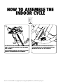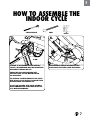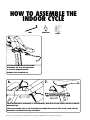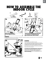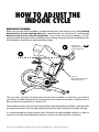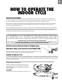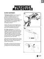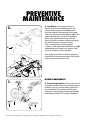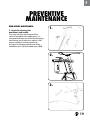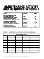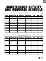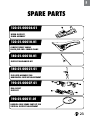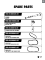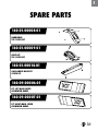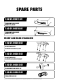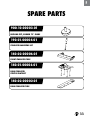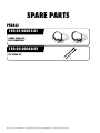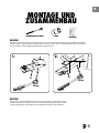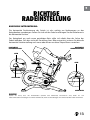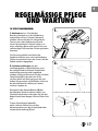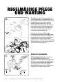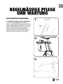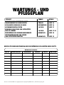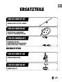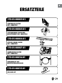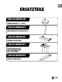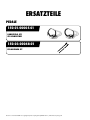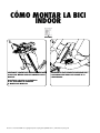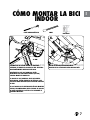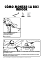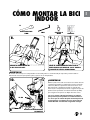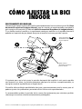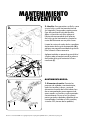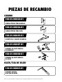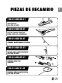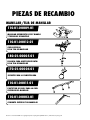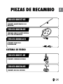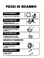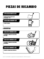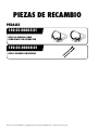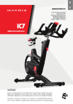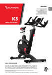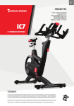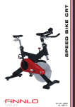
1
IC7
MODEL NO:IC-TKIC7B-01
CAUTION!
READ ALL PRECAUTIONS AND INSTRUCTIONS IN THIS MANUAL BEFORE YOU START
USING THIS EQUIPMENT. PLEASE KEEP THIS MANUAL FOR FUTURE REFERENCE.
IMPROPER ASSEMBLY, USE OR MAINTENANCE CAN VOID THE WARRANTY TERMS.
Version 1.0 2014 IC-TKIC7B-01 Copyright by Indoorcycling Group GmbH 2014 | www.indoorcycling.com
DEU
ENG
Indoorcycling Group GmbH
Happurger Str. 86
90482 Nuremberg | Germany
[email protected]
www.indoorcycling.com
Phone: +49(0)911 / 54 44 50
ESP
MANUFACTURED BY:
TABLE OF CONTENTS
IMPORTANT PRECAUTIONS P.3
GETTING STARTED P.4
HOW TO ASSEMBLE THE INDOOR CYCLE P.5-9
INSTALLATION AND DISPOSING OF BATTERIES P.10-11
HOW TO ADJUST THE INDOOR CYCLE P.12-14
HOW TO OPERATE THE INDOOR CYCLE P.15
PREVENTIVE MAINTENANCE P.16-19
MAINTENANCE ACTIVITY AND REQUIRED SCHEDULE P.20-21
SPARE PARTS P.22-34
WARRANTY P.35
TECHNICAL SPECIFICATIONS:
The TOMAHAWK IC7 Bike is, according to EN ISO 20957 (1 & 10), a Class S product for
use in a controlled environment such as sports or fitness facilities
under the supervision of a trainer.
WEIGHT OF BIKE:
54 KG
MAX USER WEIGHT: 150 KG
USER HEIGHT:
SUITABLE FOR USERS BETWEEN APPROX. 155 AND 215 CM
REQUIRED FOOT PRINT:
APPROX. 132 X 52 CM
MAX SADDLE & HANDLEBAR HEIGHT:
APPROX. 120 CM
WARNING!
The performance data shown on the display exceeds the requirements according to DIN EN
957-5 for Class A ergometers. The average achieved accuracy of < +/- 1% relates to a rotational
speed range of 40 - 120 RPM and a braking efficiency of between 50 - 900 watts.
Electronic components adhere to the EMV Directive 204/108/EC, EMV Directive 99/519/EC,
and DIN EN 60335-1 for electrical safety.
Version 1.0 2014 IC-TKIC7B-01 Copyright by Indoorcycling Group GmbH 2014 | www.indoorcycling.com
ENG
IMPORTANT
PRECAUTIONS
WARNING!
To reduce the risk of serious injury due to improper
use of the equipment, carefully read and adhere
to the following important precautions and
information before operating the indoor cycle!
1. It is the responsibility of the owner to ensure
that all users are informed of all warnings
and precautions for proper use, and are only
authorized to use the bike independently after
being successfully briefed by a qualified trainer or
instructor.
2. Do not operate the bike until it has been properly
assembled and inspected as described in this
manual.
3. Keep the indoor cycle indoors, away from moisture
and dust. Do not place the indoor cycle outdoors in
a garage or covered patio or near water or pools.
Operating temperature of the Indoor Cycle has to
be between 15°C~ 40°C Celsius (59°~104°F) at max.
humidity of 65%.
4. Always place the bike on a stable, level surface.
If the bike is to be placed on a hardwood floor or
carpet, it is recommended to place a floor mat
beneath the bike, to protect the floor
from becoming damaged.
5. The level of safety of the Indoor Bike can only be
guaranteed if it is regularly checked for possible
damage as well as wear and tear (e.g. fixing
points, E-Brake, Pedals, toe straps, etc.). Consult an
authorized service provider or the manufacturer
direct to ensure the regular inspections are properly
carried out.
6. Carry out all maintenance, care and service
procedures as described in this manual on a regular
basis. Defective parts must be replaced immediately,
and the device must not be used until the repairs
have been carried out.
Only use original parts from the manufacturer.
Repairs must only be carried out by from
manufacturer authorized service technicians.
7. Unsupervised children should be kept away from
the training device at all times.
8. Children under the age of 14 shall only be allowed
to use the indoor cycle with parental approval and
supervision of a qualified Trainer or Instructor. Use of
the bike by persons over the age of 14 only after they
are briefed by a qualified trainer or instructor.
9. The indoor cycle must not be used by persons
exceeding weight of 330 lbs/150 kg.
10. Always wear appropriate tight-fitting cycling
or athletic attire and sturdy shoes, preferably
cycling shoes, while operating the bike. Unfastened
shoelaces may become caught in the drive system
and lead to injury.
11. The bike does not have an independently-moving
flywheel. The pedals will continue to move with the
flywheel until the flywheel stops. The movement can
only be stopped by using the emergency brake or
by reducing the pedaling frequency in a controlled
manner. Always ride with resistance load to ensure
that your pedaling motion is controlled. Do not
adjust handlebar or saddle during workout.
Do not pedal backwards.
12. If you feel pain or dizziness while exercising, stop
immediately. It is recommended that you consult
a doctor if the pain does not subside for an
extended period of time.
13. All data shown on the display, especially
the Watt values generated by the integrated
power sensor serve merely as information
and to help guide training. Only exercise
within your physical limitations.
WARNING!
If you have pre-existing health problems or a disability,
it is recommended that you consult your physician, in
order to find the training method which is best suited
to you. Incorrect or extensive training can result
in serious health injuries.
The manufacturer expressly assumes no responsibility for health
risks, personal injury, property damage or consequential damages
sustained by or through the use of this device, unless it is a case of
consequential damage which can be traced back to faulty material
and/or manufacturing, and which come under the responsibility of
the manufacturer.
3
GETTING STARTED
DEAR CUSTOMER,
We would like to thank you for your confidence and purchase. With the TOMAHAWK Indoor Cycle,
you have chosen a high-quality product, which is designed according to the latest technical
developments and thus fulfils the highest standards in quality and reliability.
This high level of reliability can however only be ensured with regular care and maintenance.
Adhering to the maintenance procedures outlined in this manual will ensure a maximised
stability and prolonged lifespan in return for minimal maintenance effort. This will guarantee
long-standing, interruption-free operation.
Instructions on operation and managing training for the Coach-by-Color® computer can be
found in the computer user manual also included with delivery.
SADDLE
FLIP LEVER FOR
HORIZONTAL SADDLE ADJUSTMENT
FLIP LEVER FOR
VERTICAL SADDLE ADJUSTMENT
RESISTANCE KNOB/
EMERGENCY BRAKE
FLIP LEVER FOR
HORIZONTAL
HANDLEBAR
ADJUSTMENT
HANDLEBAR
FLYWHEEL
FLIP LEVER FOR VERTICAL
HANDLEBAR ADJUSTMENT
SHROUD
TRANSPORT WHEELS
DUAL SIDED SPD PEDAL
WARNING!
LEVELING FEET
You will find the production code for the Tomahawk IC7 Bike on the tag plate which is located on the lower left side of the
frame tube of the Indoor Bike. Please enter this production code into care and maintenance lists.
It is a strict requirement to provide the production code in all warranty claims.
Version 1.0 2014 IC-TKIC7B-01 Copyright by Indoorcycling Group GmbH 2014 | www.indoorcycling.com
ENG
HOW TO ASSEMBLE THE
INDOOR CYCLE
TORQUE WRENCH
17MM
2
PEOPLE
WARNING!
Avoid high fluctuations in temperature whilst transporting the bike from the store to the installation site.
If there are nevertheless large fluctuations in temperature, please allow the bike to acclimatise to the surrounding
temperature before proceeding with assembly.
1.
2.
50 NM
50 NM
WARNING!
Please ensure that bolts are tightened with significant force to minimize loosening
during use. If bolts are loosened after initial assembly, we recommend using
medium-strength LOCTITE® 243 when reassembling.
5
HOW TO ASSEMBLE THE
INDOOR CYCLE
2
PEOPLE
1.
SET THE VERTICAL ADJUSTMENT OF THE HANDLEBAR
STEM TO THE HIGHEST POSITION BEFORE BEGINNING
WITH ASSEMBLY.
2.
MAKE SURE THAT THE CONNECTING BRIDGES OF
THE HANDLEBARS ARE LOCATED UNDERNEATH THE
MOUNTING BRACKET FOR THE COMPUTER.
DO NOT REMOVE WARNING TAPE FROM THE SLIDERS
PRIOR TO THE HANDLEBAR BEING ASSEMBLED.
Version 1.0 2014 IC-TKIC7B-01 Copyright by Indoorcycling Group GmbH 2014 | www.indoorcycling.com
ENG
HOW TO ASSEMBLE THE
INDOOR CYCLE
TORQUE WRENCH
3.
6MM
2
PEOPLE
4.
30 NM
IN ORDER TO AVOID DAMAGING THE INTERIOR
CABLING, THE HANDLEBARS MUST NOT BE ADJUSTED
HORIZONTALLY BEFORE THIS STEP.
AFTER ASSEMBLY, REMOVE THE WARNING TAPE.
DO NOT MOVE HORIZONTAL SLIDER BACKWARDS.
ENSURE THAT BOLTS ARE TIGHTENED WITH
SUFFICIENT FORCE (30 NM) WHEN MOUNTING
THE HANDLEBARS.
THE FASTENING COUNTER SUNK BOLTS ARE COATED
WITH TUFLOK® AT THE FACTORY TO PREVENT THEM
FROM BECOMING LOOSE DURING USE.
IF BOLTS ARE LOOSENED AFTER INITIAL ASSEMBLY,
WE RECOMMEND USING HIGH-STRENGTH LOCTITE®
2701 WHEN REASSEMBLING.
7
HOW TO ASSEMBLE THE
INDOOR CYCLE
3MM
HAND TIGHT
2
PEOPLE
5.
OPEN THE FLIP LEVER FOR THE HORIZONTAL
ADJUSTMENT AND SLIDE THE HANDLEBARS
TO ITS MOST FORWARD POSITION.
ASSEMBLE THE BOTTOM END CAP.
6.
7.
CHECK THE HORIZONTAL ADJUSTMENT OF THE HANDLEBARS, WITH THE FLIP LEVER OPENED, FOR EASE OF MOTION
WHEN ADJUSTING.
CHECK THE CLAMPING FORCE OF THE HORIZONTAL ADJUSTMENT WITH THE FLIP LEVER CLOSED. MAKE SURE THE
HORIZONTAL ADJUSTMENT PERFORMS SUFFICIENTLY.
Version 1.0 2014 IC-TKIC7B-01 Copyright by Indoorcycling Group GmbH 2014 | www.indoorcycling.com
ENG
HOW TO ASSEMBLE THE
INDOOR CYCLE
1X
15 MM
PEDAL WRENCH
3MM
8.
HAND TIGHT
2
PEOPLE
9.
INSERT THE BIKE COMPUTER
INTO THE COMPUTER BRACKET.
FASTEN THE BIKE COMPUTER INTO PLACE FROM
THE UNDERSIDE OF THE HANDLEBARS WITH
THE BOLT AND PLASTIC SLEEVE PROVIDED.
WARNING!
The user manual for the IC7 Coach By Color® computer is enclosed separately and contains all the necessary information
for setting up and operating the computer.
10.
L
Attach the pedal marked R on the right
crank and tighten by turning clockwise (standard righthand thread). Attach the pedal marked L on the left crank
and tighten by turning counter-clockwise (left-hand
thread). Please make sure that both pedals are fastened
with sufficient force (55 NM), to ensure that the bolt does
not become loose during use.
The threads are provided with TufLok® at the factory
to prevent them from becoming loose during use.
If bolts are loosened after initial assembly, we
recommend using medium-strength LOCTITE® 243
when reassembling.
55 NM
R
WARNING!
OBSERVE ASSEMBLY
INSTRUCTIONS!
9
INSTALLATION AND
DISPOSING OF BATTERIES
Instructions stated in this manual must be performed during initial installation of the
TOMAHAWK Indoor Cycle in order to ensure optimal performance and a long lifespan. Please
read and follow the following instructions carefully. If the Indoor Cycles are not installed and
configured as described, the components may be subjected to excessive wear and tear and the
bike may become damaged. If you have any questions regarding installation, please contact
[email protected].
Please note: Lubricants are required for some maintenance procedures. Please only use an
acid- and solvent-free spray lubricant (e.g. Brunox) and white lithium grease.
1. Make sure the bike is level. If bike rocks on the floor, turn the levelling feet underneath the
front and/or rear stabilizer until the rocking motion is eliminated. Make sure that the levelling
feet are not screwed out further than 10 mm
2. Verify emergency brake function to make sure that it is working properly.
3. Check that both crank arm Allen bolts, with which the cranks (on the right and left side of the
bottom bracket) are fastened, are secure (tightening torque 60 NM). These bolts are provided
with TufLok® at the factory to prevent them from becoming loose during use.
If the bolts become lose, we recommend applying medium-strength LOCTITE® 243 and then
reattaching the crank fixing bolts with a tightening torque of 60 NM.
4. Wipe down bike frame with a rag moistened with solvent-free spray lubricant.
5. Some parts of the bike may become loose during shipment. Check crank arms and all exposed
screws, bolts and nuts, and make sure that they are all secure and properly tightened.
Version 1.0 2014 IC-TKIC7B-01 Copyright by Indoorcycling Group GmbH 2014 | www.indoorcycling.com
ENG
INSTALLATION AND
DISPOSING OF BATTERIES
CUSTOMER SERVICE
1. Provide the customer with basic maintenance instructions, and direct them to detailed
maintenance instructions.
2. Have the sign-off sheet for the manual, explanation of maintenance procedures and
verification of impeccable condition of the bikes confirmed by the customer when handing over
the goods. A copy of this confirmation counter-signed by yourself is withheld by the customer.
3. Repairs must only be carried out by manufacturer authorised service technicians.
BATTERIES MAY NOT:
• come into contact with fire
• come into contact with coins or other metallic objects
If the device remains unused for an extended period of time, remove the battery in order to
avoid damage due to leakage or corrosion. If the battery leaks, remove all residues immediately
and insert a new battery. If you make contact with any residues, carefully remove them.
Products or batteries labelled with this symbol may not be disposed of along with normal
household refuse. For proper disposal, please find out about the applicable laws or guidelines
on disposing of electrical devices and batteries in your local area and adhere to them.
11
HOW TO ADJUST THE
INDOOR CYCLE
The Tomahawk Indoor Cycle can be very easily adjusted, depending on the requirements of
various user groups. This enables maximum riding comfort to be ensured whilst achieving
optimal training results. The configurations described in the following paragraphs demonstrate
just a few of the most often used adjustment variations of which the Indoor Cycle is capable. It
is up to the user to adjust the Indoor Cycle to a riding position best suited to their requirements.
ADJUSTING THE SEAT HEIGHT:
Sit on the saddle and ensure that your hip is not tilted to one side when the pedal has assumed
the position as shown in the picture. Place your shoes in the toe clips (cages) on the pedals,
or in the SPD cleats if you are using cycling shoes, if your Indoor Cycle is not fitted with a
combi pedal system.
VERTICAL SADDLE
ADJUSTMENT
VERTICAL HANDLEBAR
ADJUSTMENT
OPEN
OPEN
CLOSED
CLOSED
WARNING!
Do not adjust seat and handlebar during exercise. Ensure that all flip levers (vertical and horizontal) are closed, before you
sit on the bike and always step off the bike when making adjustments to the handlebars and/or saddle.
Start pedalling slowly, until the pedal has reached the position as shown in the picture. The vertical saddle sliders should
be adjusted so that your knees are always slightly bent when this pedal position is reached, without dropping your hip
one side. Rule of thumb: When standing next to the bike, the upper edge of the saddle should be a hand‘s width/four
fingers below your iliac crest. Please avoid cycling with your knees fully extended or your hip tilted to one side.
Version 1.0 2014 IC-TKIC7B-01 Copyright by Indoorcycling Group GmbH 2014 | www.indoorcycling.com
ENG
HOW TO ADJUST THE
INDOOR CYCLE
ADJUSTING THE SADDLE HORIZONTALLY:
Properly positioning the saddle horizontally is very important in order to avoid injury to the
knees. Sit on the saddle and move the pedals until the crank arms are in the horizontal position.
The knee of your forward-facing leg should be positioned directly above the centre of the pedal.
If this does not correspond to your bike‘s setting, please align the horizontal saddle adjustment
to the front or rear in order to attain this seat position.
HORIZONTAL
SADDLE ADJUSTMENT
HORIZONTAL
HANDLEBAR ADJUSTMENT
OPEN
OPEN
CLOSED
CLOSED
WARNING!
Ensure that all flip levers (vertical and horizontal) are closed, before sitting on the bike and always step off the bike when
making adjustments to the handlebars and/or saddle.
13
HOW TO ADJUST THE
INDOOR CYCLE
HANDLEBAR POSITIONING:
Begin with the top of the handlebars at approximately the same height as the saddle (dotted
horizontal line A in the drawing below) for inexperienced users set to the “0“ marking (see
dotted vertical line B in the drawing below). If your knees touch the handlebars or if you
experience back discomfort when pedalling in the standing riding position for extended periods,
the handlebars should first be adjusted slightly higher.
B.
Horizontally
adjusting the handlebars
using the flip lever
A.
Vertically
adjusting the handlebars
using the flip lever
The next step is to adjust the horizontal position of the handlebars as precisely as possible to
your height. An ideal and protective seating position for inexperienced riders is achieved if your
back assumes an inclination at an angle of 45°.
The handlebars offer a wide variety of hand positions and adjustment possibilities, which provide
the experienced rider with every possibility to find his/her ideal seating and hand positioning.
It is recommended to change hand positions frequently during extended workouts in order to
minimise one-sided and monotonous exertions on your muscles, ligaments and joints.
Version 1.0 2014 IC-TKIC7B-01 Copyright by Indoorcycling Group GmbH 2014 | www.indoorcycling.com
ENG
HOW TO OPERATE THE
INDOOR CYCLE
RESISTANCE ADJUSTMENT:
The resistance adjustment can be set precisely and regulated in fine increments according to the requirements of
the cyclist using the resistance adjustment knob with a range of motion of 300°. The resistance in % (where 0% is no
resistance and 100% is maximum resistance) is also displayed on the Indoor Cycle computer display.
To increase the resistance, turn the resistance adjustment knob clockwise. To decrease the resistance, turn it counterclockwise. For a magnetic brake system, like the one fitted to this Indoor Cycle, the magnetic resistive effect also
increases with pedalling frequency.
Never pedal backwards under resistance, as this can loosen the screws between the pedals and the crank arm and the
two may even become detached. To stop the flywheel during use, the resistance knob/emergency brake knob must be
pressed down. During training, please make sure your shoes are placed in the toe clips (cages) provided or if you are
using cycling shoes, that they are connected with the SPD cleats.
The Indoor Bike does not have a free-moving flywheel. The flywheel is firmly connected to the pedals and does
not stop independently if the user stops pedalling. Please always check your movements and reduce speed
in a controlled manner to stop or simply press the red resistance/emergency brake knob down to quickly
slow down the movement and in so doing bring the flywheel to a stop and suspend the training session.
Emergency brake = press down red resistance/emergency knob.
If the emergency brake has been activated, it can only be disengaged again when the flywheel has come
to a complete standstill and the pressure has been removed from the pedals.
RESISTANCE KNOB (TURN RESISTANCE ADJUSTMENT KNOB)
EMERGENCY BRAKE (PRESS RESISTANCE ADJUSTMENT KNOB)
For safety reasons, please always make sure you pedal in a controlled manner and
adjust your pedalling frequency to your own cycling capabilities.
MOVING THE INDOOR CYCLE:
It is recommended that two people move the Indoor Cycle. In order to prevent accidents and damage to the plug-in
sockets of the handlebars it is necessary to firmly fix the vertical handlebar adjustment before the wheel is tilted. Please
take extra care when moving the Indoor Cycle over uneven surfaces. A second person is advisable here, to prevent the
cycle from tilting to one side.
Allow a minimum safety distance away from the nearest equipment of at least 50 cm to the left and right
and 90 cm to the front and rear.
Check the stability of the Indoor Cycle where it is to
be operated and if necessary adjust the levelling feet
underneath the front or rear stabilizers to ensure the
desired stability.
IMPORTANT!
Please do not unscrew the levelling feet more than 1 cm!
LEVELLING FEET
15
PREVENTIVE
MAINTENANCE
WARNING!
Please carefully observe the following instructions. The maintenance and care procedures
must be performed in the regularity set out, to ensure maximum operating safety and lifespan.
Irregularly observed maintenance and care procedures will lead to increased wear to the
product and will void the warranty. If you have any further questions on this topic, please
contact our technical support.
Please only use the acid- and solvent-free maintenance and care agent (e.g. Brunox)
recommended by us to prevent damage to components of the Indoor Cycle.
DAILY MAINTENANCE:
1. Make sure that the Indoor Cycle is leveled and does not rock
(if necessary adjust as described on p.15).
2. Cleaning: The Indoor Cycle must be regularly cleaned after each use for reasons of hygiene.
Ensure that there are sufficient soft cloths or paper towels and maintenance and disinfection
agent available. First disinfect the saddle and handlebars with a suitable agent and then wipe all
bodily residues off the entire Indoor Cycle.
WEEKLY MAINTENANCE:
1. Cleaning: Depending on how often the Indoor Cycle is used, it must be extensively cleaned
once a week. To do this, spray a maintenance spray onto a soft cloth and clean all plastic parts,
the entire flywheel, exposed framework parts including stabilizers and the plastic casing.
Never spray the maintenance spray directly onto the flywheel, as this could cause the drive belt
to slip through (belt slip).
Version 1.0 2014 IC-TKIC7B-01 Copyright by Indoorcycling Group GmbH 2014 | www.indoorcycling.com
ENG
PREVENTIVE
MAINTENANCE
BI-WEEKLY MAINTENANCE:
1. Emergency brake: To ensure operating
safety, the emergency brake must be
regularly checked to make sure it is
functioning properly. To do this, press
down the red emergency brake handle
whilst pedalling. When functioning optimally,
it should produce an immediate braking
effect and bring the flywheel to
a complete standstill.
The flywheel is only released again by the
emergency braking function after coming
to a complete standstill and when the
pressure is removed from the pedals.
2. Saddle adjustments: To maintain the
easy adjustment, the vertical and horizontal
saddle posts must be regularly cleaned and
lubricated. To do this, position the vertical
saddle post (A) in the uppermost position,
spray with maintenance spray and rub down
the entire exterior surfaces including the
horizontal post with a soft cloth.
1.
2.
A
Clean sweat residues off the contact surfaces
(B) of the horizontal saddle post beforehand
and if necessary apply a small amount of
lithium/silicone grease.
Also apply some lithium/silicone grease as
required to the clamp mechanism of the
clamping lever of the horizontal post (C).
B
C
17
PREVENTIVE
MAINTENANCE
3. Handlebars: To maintain the easy
adjustment of the handlebar posts, the
vertical and horizontal handlebar posts
must be regularly cleaned and lubricated.
To do this, position the handlebars (A) in the
uppermost position, spray the handlebar
posts with maintenance spray and rub
down the entire exterior surfaces including
the horizontal post with a soft cloth.
Clean sweat residues off the contact
surfaces of the horizontal handlebar post (B)
beforehand and if necessary apply a small
amount of lithium/silicone grease.
3.
A
Also apply some lithium/silicone grease as
required to the clamp mechanism of the flip
lever of the horizontal post (C).
C
B
1.
MONTHLY MAINTENANCE:
1. Connecting elements: During the course
of regular maintenance and care procedures,
all bolts, nuts etc. on the Indoor Cycle must
be checked for firm seating and function,
and parts showing wear or damage (saddle,
pedal teeth, pedals, SPD system) replaced.
Version 1.0 2014 IC-TKIC7B-01 Copyright by Indoorcycling Group GmbH 2014 | www.indoorcycling.com
ENG
PREVENTIVE
MAINTENANCE
USER-DEFINED MAINTENANCE:
1. Vertically adjusting the
handlebars and saddle:
To ensure the easy adjustment of the
vertical handlebar and saddle posts, it is
recommended that you check the clamping
mechanism and if necessary apply a small
amount of lithium/silicone grease to
the vertical clamping mechanism of the
handlebar posts (1) and saddle posts (2/3).
1.
2.
3.
19
MAINTENANCE ACTIVITY
AND REQUIRED SCHEDULE
ACTIVITY
ROTATIONDETAILS
FEET LEVELLING, DISINFECTION
& CLEANING OF THE BIKE
DAILY
P 16
SERVICING BRAKE PADS, DETAILED
CLEANING OF THE ENTIRE BIKE
WEEKLY
P 16
CHECK EMERGENCY BRAKE FUNCTION
BI-WEEKLY
P 17
CLEAN AND LUBRICATE SADDLE
& HANDLEBAR SLIDERS / POSTS
BI-WEEKLY P 17-18
CHECK ALL CONNECTIONS AND FIXINGS
MONTHLY
P 18
VERTICALLY ADJUSTING
THE HANDLEBARS AND SADDLE
MONTHLY
P 19
EXAMPLES OF MAINTENANCE PLAN CHARTS FOR IN-HOUSE SERVICE TECHNICIANS:
WEEKLY MAINTENANCE CHECKLIST
BIKE NO.
PRODUCTION CODE
OBSERVATIONS
ACTION TAKEN
RESULT
Version 1.0 2014 IC-TKIC7B-01 Copyright by Indoorcycling Group GmbH 2014 | www.indoorcycling.com
NAME / DATE
ENG
MAINTENANCE ACTIVITY
AND REQUIRED SCHEDULE
BI-WEEKLY MAINTENANCE CHECKLIST
BIKE NO.
PRODUCTION CODE
OBSERVATIONS
ACTION TAKEN
RESULT
NAME / DATE
RESULT
NAME / DATE
MONTHLY MAINTENANCE CHECKLIST
BIKE NO.
PRODUCTION CODE
OBSERVATIONS
ACTION TAKEN
21
SPARE PARTS
FRAME
100-01-00004-01
INLAY SLEEVE SET FOR HANDLEBAR TUBE
100-01-00006-01
INLAY SLEEVE SET FOR SEATPOST TUBE
100-01-00009-01
LEFT FLYWHEEL SUPPORT ARM KIT
100-01-00007-01
VERTICAL HANDLEBAR
ADJUSTMENT ASSEMBLY
100-01-00008-01
VERTICAL SEATPOST
ADJUSTMENT ASSEMBLY
SEAT/SEAT POST
120-01-00005-01
LOWER
SEATPOST ASSEMBLY
Version 1.0 2014 IC-TKIC7B-01 Copyright by Indoorcycling Group GmbH 2014 | www.indoorcycling.com
ENG
SPARE PARTS
120-01-00006-01
UPPER SEATPOST
SLIDER ASSEMBLY
120-01-00010-01
COMFORT SPORT SADDLE
BLACK/RED INCL. SADDLE CLAMP
180-01-00018-01
SEATPOST GASDAMPER KIT
180-01-00021-01
FLIP LEVER ASSEMBLY FOR
HORIZONTAL SEATPOST ADJUSTMENT
190-01-00007-01
END CAP SET
SEATPOST
190-01-00011-01
BOWDEN CABLE SPARE PART KIT FOR
VERTICAL SEATPOST ADJUSTMENT
23
SPARE PARTS
HANDLEBAR/HANDLEBAR STEM
110-01-00009-01
HANDLEBAR WITH SOFT PVC
COATING & MOUNTING BOLTS
110-01-00012-01
UPPER HANDLEBAR
SLIDER ASSEMBLY
180-01-00005-01
FLIP LEVER ASSEMBLY FOR
HORIZONTAL HANDLEBAR ADJUSTMENT
170-01-00004-01
CONSOLE BRACKET ASSEMBLY
110-01-00011-01
CABLE COVER KIT FOR UPPER
HORIZONTAL HANDLEBAR SLIDER
110-01-00003-01
LOWER HANDLEBAR STEM ASSEMBLY
Version 1.0 2014 IC-TKIC7B-01 Copyright by Indoorcycling Group GmbH 2014 | www.indoorcycling.com
ENG
SPARE PARTS
180-01-00017-01
HANDLEBAR GASDAMPER KIT
190-01-00010-01
BOWDEN CABLE SPARE PART KIT FOR
VERTICAL HANDLEBAR ADJUSTMENT
190-01-00006-01
END CAP SET
FOR HANDLEBAR
BRAKE SYSTEM
130-01-00011-01
UPPER BRAKE ASSEMBLY
130-01-00014-01
BRAKE DIAL KIT
25
SPARE PARTS
190-01-00008-01
EMERGENCY BRAKE SPARE PART KIT
190-01-00009-01
LOWER EDDY CURRENT BRAKE
SPARE PART KIT
190-01-00012-01
BOWDEN CABLE SPARE PART KIT
FOR EMERGENCY BRAKE
190-01-00013-01
BOWDEN CABLE SPARE PART KIT
FOR LOWER EDDY CURRENT BRAKE
DRIVE GEAR
150-01-00022-01
CAM PULLEY
72 TEETH KIT
150-01-00023-01
CRANK PULLEY
MOUNTING BOLTS
Version 1.0 2014 IC-TKIC7B-01 Copyright by Indoorcycling Group GmbH 2014 | www.indoorcycling.com
ENG
SPARE PARTS
150-01-00024-01
FLYWHEEL
AXLE KIT
900-00-90008-20
CRANK MOUNTING BOLT,
M8X20X1,25P
190-01-00014-01
FLYWHEEL SPARE PART ASSEMBLY
150-03-00044-01
POLY V BELT,
4PK 895 FOR SECONDARY DRIVE
150-03-00045-01
POLY V BELT,
2PJ 330 FOR GENERATOR DRIVE
150-03-00059-01
TIMING BELT,
784 8MHL 12 FOR PRIMARY DRIVE
27
SPARE PARTS
150-01-00016-01
PRIMARY DRIVE IDLER PULLEY ASSEMBLY
150-01-00018-01
SECONDARY DRIVE IDLER PULLEY ASSEMBLY
150-03-00054-01
LEFT CRANK ARM, RED
150-03-00053-01
RIGHT CRANK ARM, RED
ELECTRONICS
170-01-00004-01
CONSOLE BRACKET ASSEMBLY
150-01-00017-01
GENERATOR ASSEMBLY
Version 1.0 2014 IC-TKIC7B-01 Copyright by Indoorcycling Group GmbH 2014 | www.indoorcycling.com
ENG
SPARE PARTS
170-01-00009-01
POWER MODULE
PCB ASSEMBLY
170-01-00005-01
GEAR MODULE
PCB ASSEMBLY
170-01-00006-01
PHOTO INTERRUPTER
PCB KIT
170-01-00007-01
GAMMA SENSOR
PCB ASSEMBLY
170-01-00016-01
MAIN CABLE HARNESS SET WITH
IDENTIFICATION STICKER
170-01-00015-01
USB CABLE SET
29
SPARE PARTS
170-03-00012-01
LIPO RECHARGEABLE BATTERY
5000MAH/3.7V
320-00-00009-01
CONSOLE KIT
SHROUD
160-01-00004-01
RIGHT SIDE
MAIN SHROUD KIT
160-01-00006-01
LEFT SIDE
MAIN SHROUD KIT
160-01-00007-01
TOP
MAIN COVER KIT
Version 1.0 2014 IC-TKIC7B-01 Copyright by Indoorcycling Group GmbH 2014 | www.indoorcycling.com
ENG
SPARE PARTS
160-01-00008-01
HANDLEBAR
TOP COVER KIT
160-01-00009-01
SEATPOST
TOP COVER KIT
160-01-00014-01
GAS DAMPER BRACKET
COVER KIT
160-09-00006-01
IC7 LEFT MAIN COVER
ALUMINUM BADGE
160-09-00007-01
IC7 RIGHT MAIN COVER
ALUMINUM BADGE
31
SPARE PARTS
160-01-00011-01
TOMAHAWK LOGO PLATE
INSERT KIT, RIGHT
160-01-00010-01
TOMAHAWK LOGO PLATE
INSERT KIT, LEFT
FRONT AND REAR STABILIZER
140-01-00004-01
FRONT STABILIZER
PROTECTION PLATE KIT, LEFT
140-01-00005-01
FRONT STABILIZER
PROTECTION PLATE KIT, RIGHT
140-01-00003-01
TRANSPORTATION WHEEL KIT
140-03-00001-01
STABILIZER END CAP
Version 1.0 2014 IC-TKIC7B-01 Copyright by Indoorcycling Group GmbH 2014 | www.indoorcycling.com
ENG
SPARE PARTS
900-10-00003-01
LEVELING FEET, RUBBER 75° SHORE
190-01-00004-01
STABILIZER MOUNTING KIT
140-02-00006-01
FRONT STABILIZER TUBE
140-01-00006-01
REAR STABILIZER
STRETCH PLATE KIT
140-02-00002-01
REAR STABILIZER TUBE
33
SPARE PARTS
PEDALS
150-01-00005-01
COMBI PEDAL SET,
SPD COMPATIBLE
150-03-00048-01
TOE STRAP SET
Version 1.0 2014 IC-TKIC7B-01 Copyright by Indoorcycling Group GmbH 2014 | www.indoorcycling.com
ENG
WARRANTY
ICG warrants that all new equipment will be free of manufacturing defects in workmanship and materials,
effective on the date of original assembly at its production facility. Parts repaired or replaced under the terms
of this warranty will be warranted for the remainder of the original warranty period only. ICG is obligated to
uphold its manufacturer warranty obligation so long as the product is used in the closed environment it was
designed for, Temperature range between 15ºC~40°C Celsius (59ºF~104°F) and max. 65% humidity (not near
a swimming pool or outdoors). Defects caused by obvious deliberate mechanical impact, inappropriate use
or undo handling of the product may cause the manufacturer’s warranty to become void. In order for the
manufacturer to uphold the warranty coverage, the customer (fitness facility) is obligated to maintain and
service the product as per the manufacturer’s specifications stated in the owner manual of each product.
5 YEARS WARRANTY:
FRAME CONSTRUCTION AND WELDING
3 YEARS WARRANTY:
POWDER COATING (PAINT CRACKS, CORROSION)
HANDLEBAR AND SEAT POST ASSEMBLY
(ALUMINUM PARTS AND PVC COATING)
DUAL BELT DRIVE SYSTEM
POWER SENSOR
BOTTOM BRACKET ASSEMBLY
FLYWHEEL AND HUB ASSEMBLY
CRANKS
PEDALS (EXCLUDED BINDING SYSTEM AND STRAPS)
INSERT SLEEVES FOR HANDLE BAR AND SEAT POST
BOWDEN CABLES (BRAKE ADJUSTMENT, EBRAKE ACTIVATION,
GAS DAMPER ACTIVATION CABLE SP &HB VERTICAL ADJUSTMENT)
BRAKE SYSTEM
GAS DAMPERS
FLIP LEVER ASSEMBLY
FOR HORIZONTAL AND VERTICAL ADJUSTMENT ( HB & SP)
LEVELLING FEET
SHROUD AND TOP COVERS
1 YEAR WARRANTY:
ELECTRONIC COMPONENTS
(CONSOLE, CABLE HARNESS, PCBS AND SENSORS, GENERATOR)
LITHIUM POLYMER (LIPO) BATTERY
SADDLE CONSTRUCTION (EXCLUDED STITCHING AND SADDLE SURFACE)
THE FOLLOWING WEAR ITEMS ARE EXCLUDED FROM WARRANTY:
Pedal straps, pedal binding system, saddle surface.
35
CAUTION.
READ ALL PRECAUTIONS AND INSTRUCTIONS IN THIS MANUAL
BEFORE YOU BEGIN USING THIS EQUIPMENT. PLEASE KEEP
THIS MANUAL FOR FUTURE REFERENCE. IMPROPER ASSEMBLY,
SET UP, USE OR MAINTENANCE MAY VOID THE WARRANTY.
EMAIL: [email protected]
WEBSITE: WWW.INDOORCYCLING.COM
© 2014 Indoorcycling Group
Manufactured by: Indoorcycling Group® GmbH
Happurger Str. 86 90482 Nuremberg Germany
Indoorcycling Group GmbH
Happurger Str. 86
90482 Nuremberg | Germany
[email protected]
www.indoorcycling.com
Phone: +49(0)911 / 54 44 50
IC7
MODELL NR:IC-TKIC7B-01
WICHTIGER HINWEIS!
BITTE LESEN SIE VOR DER INBETRIEBNAHME DES BIKES DIESES HANDBUCH VOLLSTÄNDIG
UND BEFOLGEN SIE ALLE DARIN BESCHRIEBENEN ANLEITUNGEN ZU MONTAGE,
WARTUNG UND BETRIEB DES GERÄTES NICHT ORDNUNGSGEMÄSSE HANDHABUNG
ODER UNZUREICHENDE WARTUNG FÜHRT ZUM ERLÖSCHEN DER GARANTIE!
Version 1.0 2014 IC-TKIC7B-01 Copyright by Indoorcycling Group GmbH 2014 | www.indoorcycling.com
DEU
HERSTELLER:
INHALTSVERZEICHNIS
WICHTIGE SICHERHEITSHINWEISE S.3
EINFÜHRUNG S.4
MONTAGE UND ZUSAMMENBAU S.5-9
INSTALLATION, AUFBAU S.10-11
RICHTIGE RADEINSTELLUNG S.12-14
RICHTIGE HANDHABUNG DES BIKES S.15
REGELMÄSSIGE PFLEGE UND WARTUNG S.16-19
WARTUNGS - UND PFLEGEPLAN S.20-21
ERSATZTEILE S.22-34
GARANTIE S.35
TECHNISCHE DATEN:
Das Tomahawk IC7 Bike entspricht nach EN ISO 20957 (Teil 1 & 10) der Benutzerklasse S
und ist für die Verwendung in kontrollierter Umgebung wie z.B. Sportstätten und
Fitnesseinrichtungen unter Beaufsichtigung eines Trainers klassifiziert.
GEWICHT DES BIKES:
54 KG
MAXIMALES BENUTZERGEWICHT: 150 KG
BENUTZERGRÖSSE:
GEEIGNET FÜR KÖRPERGRÖSSEN VON CA. 155 - 215 CM
BENÖTIGTE STANDFLÄCHE:
CA. 132 X 52 CM
MAX. SATTEL UND LENKERHÖHE:
CA. 120 CM
WICHTIG!
Die auf dem Display angezeigten Leistungsdaten übertreffen die Anforderungen nach
DIN EN 957-5 für Klasse A Ergometer. Die erreichte Genauigkeit von durchschnittlich
< +/- 1% bezieht sich auf einen Drehzahlbereich von 40 - 120 RPM und
einer Bremsleistung zwischen 50 - 900 Watt.
Elektronische Bauteile entsprechen der EMV Richtlinie 204/108/EC,
EMV Richtlinie 99/519/EC, sowie der DIN EN 60335-1 für elektrische Sicherheit.
Version 1.0 2014 IC-TKIC7B-01 Copyright by Indoorcycling Group GmbH 2014 | www.indoorcycling.com
DEU
WICHTIGE
SICHERHEITSHINWEISE
WARNUNG!
Um einem Sicherheitsrisiko durch unsachgemäße
Handhabung des Gerätes vorzubeugen ist es
erforderlich, die nachfolgenden Sicherheitshinweise
und Informationen vor der Inbetriebnahme des
Gerätes im Detail zu lesen und zu beachten!
1. Es liegt in der alleinigen Verantwortung des
Eigentümers, alle Nutzer über die sachgerechte und
ordnungsgemäße Verwendung zu informieren und erst
nach erfolgter Einweisung durch einen qualifizierten
Trainer oder Instruktor die eigenständige Nutzung des
Bikes zu autorisieren.
2. Benutzen Sie das Bike erst nach ordnungsgemäßer
Montage und deren Überprüfung wie in diesem
Handbuch beschrieben.
3. Verwenden Sie das Bike nicht im Freien und setzen Sie
es keiner feuchten und/oder staubigen Umgebung aus.
Das Gerät wurde für die Verwendung in geschlossenen,
trockenen Räumen bei Umgebungstemperaturen
zwischen 15°C~40°C Celsius bei max. Luftfeuchtigkeit
von 65% konzipiert.
4. Platzieren Sie das Bike immer auf einem standsicheren,
ebenen und zugleich horizontalen Untergrund. Falls
Sie das Bike auf Teppich- oder Parkettböden platzieren,
empfiehlt es sich eine Unterlegmatte zu verwenden,
um eventuellen Beschädigungen des
Bodenbelags vorzubeugen.
5. Das Sicherheitsniveau des Indoor Bikes kann nur
gewährleistet werden, wenn dieses regelmäßig
auf Schäden und Verschleiß überprüft wird (z.B.
Verbindungsstellen, Pedalriemen etc.). Beauftragen
Sie ggfs. einen autorisierten Kundendienst um eine
regelmäßige Überprüfung der Betriebssicherheit zu
gewährleisten oder wenden Sie sich an den Hersteller.
6. Bitte führen Sie alle in diesem Handbuch
beschriebenen Pflege- und Wartungsarbeiten
regelmäßig durch. Defekte Teile sind umgehend zu
ersetzen und das Gerät bis zur erfolgten Instandsetzung
nicht mehr zu benutzen. Verwenden Sie ausschließlich
original Ersatzteile des Herstellers. Reparaturen dürfen
nur durch vom Hersteller autorisierte Servicetechniker
durchgeführt werden.
7. Unbeaufsichtigte Kinder sind generell vom
Trainingsgerät fernzuhalten.
8. Kindern unter 14 Jahren ist es nicht erlaubt das Bike
ohne Aufsicht durch einen dazu qualifizierten Trainer zu
verwenden. Verwendung des Gerätes für Personen über
14 Jahren nur nach vorheriger Einweisung durch
einen qualifizierten Trainer.
9. Das Bike ist für ein maximales Benutzergewicht
von 150 KG ausgelegt. Das Bike darf nicht von
Personen benutzt werden, die dieses max. zulässige
Benutzergewicht überschreiten.
10. Es ist darauf zu achten, nur mit eng anliegender Radoder Sportbekleidung zu fahren und festes Schuhwerk,
vorzugsweise Radschuhe, zu tragen. Lose Schnürsenkel
können sich im Antriebssystem verfangen und
zu Verletzungen führen.
11. Das Bike verfügt über keinen Freilauf. Die Pedale
sind über den Antrieb direkt mit dem Schwungrad
verbunden. Die Bewegung kann nur durch Betätigen
der Notbremse oder durch kontrolliertes Reduzieren
der Trittfrequenz gestoppt werden. Aus Gründen
der Benutzersicherheit sollte niemals komplett ohne
Bremswiderstand gefahren und keine Einstellungen am
Lenker und Sattel während des Trainings durchgeführt
werden. Nicht rückwärts treten.
12. Bei Schwindelgefühl oder Übelkeit sollte das Training
sofort unterbrochen werden. Es empfiehlt sich einen
Arzt zu konsultieren, falls sich dieses Unwohlsein
nicht kurzfristig bessert.
13. Die im Display angezeigten Daten insbesondere
die der integrierten Leistungsmessung dienen zur
Information und Trainingssteuerung. Trainieren Sie nur
innerhalb Ihrer physischen Leistungsfähigkeit.
WICHTIGER HINWEIS:
Falls Sie gesundheitliche Probleme haben oder
vorbelastet sind, empfiehlt es sich einen Arzt zu
konsultieren, um die für Sie am besten geeignete
Trainingsmethode zu finden. Zu hohe Trainingsbelastung
oder -intensität sowie die unsachgemäße Nutzung
des Bikes kann zu gesundheitlichen Schäden und
ernsthaften Verletzungen führen.
Der Hersteller übernimmt ausdrücklich keine Verantwortung für
gesundheitliche Risiken, Schäden oder Folgeschäden die durch die
Benutzung dieses Gerätes entstehen können insofern es sich hierbei
nicht um Folgeerscheinungen handelt, die auf Material- und/oder
Herstellungsmängel zurückzuführen sind und in der
Verantwortung des Herstellers liegen.
3
EINFÜHRUNG
SEHR GEEHRTER KUNDE,
wir möchten uns für Ihr Vertrauen und Ihre Kaufentscheidung bedanken. Mit dem Tomahawk
Indoor Cycle haben Sie sich für ein Qualitätsprodukt entschieden, dass nach den neuesten
technischen Erkenntnissen entwickelt und somit auf höchste Beanspruchung und Zuverlässigkeit
ausgelegt wurde.
Dieses Höchstmaß an Zuverlässigkeit lässt sich jedoch nur über eine regelmäßige Pflege und
Wartung sicherstellen. Bei entsprechender Einhaltung der in diesem Handbuch beschriebenen
Maßnahmen wird eine maximale Standfestigkeit und Lebensdauer bei minimalem
Wartungsaufwand an den Tag gelegt. Dies garantiert Ihnen einen langjährigen, störungsfreien
Betrieb.
Hinweise zur Bedienung und Trainingssteuerung für den Coach By Color® Computer entnehmen
Sie dem ebenfalls im Lieferumfang enthaltenen Benutzerhandbuch.
SATTEL
BREMSEINSTELLGRIFF/NOTBREMSE
ARRETIERHEBEL FÜR
HORIZONTALE SATTELVERSTELLUNG
ARRETIERHEBEL FÜR
HORIZONTALE
LENKERVERSTELLUNG
ARRETIERHEBEL FÜR
VERTIKALE SATTELVERSTELLUNG
LENKER
SCHWUNGSCHEIBE
ARRETIERHEBEL FÜR VERTIKALE
LENKERVERSTELLUNG
VERKLEIDUNG
TRANSPORTROLLE
KOMBIPEDAL
WICHTIG!
STANDFUSS
Den individuellen Produktionscode des Tomahawk IC7 Bikes finden Sie auf dem Typenschild, dass sich im unteren Bereich
des Rahmenrohrs in Fahrtrichtung links des Indoor Bikes befindet. Bitte tragen Sie diesen Produktionscode in die Pflegeund Wartungslisten ein. Die Angabe des Produktionscodes ist bei allen Garantieanfragen zwingend erforderlich.
Version 1.0 2014 IC-TKIC7B-01 Copyright by Indoorcycling Group GmbH 2014 | www.indoorcycling.com
DEU
MONTAGE UND
ZUSAMMENBAU
DREHMOMENTSCHLÜSSEL
17MM
2
PERSONEN
WICHTIG!
Vermeiden Sie hohe Temperaturschwankungen zwischen dem Transport des Bikes und dem Ort der Installation.
Sollten dennoch unterschiedliche Temperaturen herrschen, muss mit der Inbetriebnahme gewartet werden,
bis sich das Bike an die Umgebungstemperatur angeglichen hat.
1.
2.
50 NM
50 NM
WICHTIG!
Sicherstellen, dass alle Verbindungselemente ausreichend fest angezogen wurden.
Werden Schraubverbindungen nach der initialen Montage gelöst, wird bei einer
erneuten Montage die Verwendung von mittelfestem LOCTITE® 243 empfohlen.
5
MONTAGE UND
ZUSAMMENBAU
2
PERSONEN
1.
BRINGEN SIE DIE VERTIKALVERSTELLUNG DES
LENKERS IN DIE MAXIMALPOSITION BEVOR
SIE MIT DER MONTAGE BEGINNEN.
2.
ACHTEN SIE DARAUF, DASS SICH DIE
VERBINDUNGSBRÜCKE DES LENKERS UNTERHALB
DER HALTERUNG FÜR DEN COMPUTER BEFINDET.
ACHTUNG!
DEN AUFKLEBER ERST ENTFERNEN NACHDEM DER
LENKER MONTIERT WURDE.
Version 1.0 2014 IC-TKIC7B-01 Copyright by Indoorcycling Group GmbH 2014 | www.indoorcycling.com
DEU
MONTAGE UND
ZUSAMMENBAU
DREHMOMENTSCHLÜSSEL
3.
6MM
2
PERSONEN
4.
30 NM
UM EINE BESCHÄDIGUNG DER INNENLIEGENDEN
KABELFÜHRUNG ZU VERMEIDEN, DARF DER
LENKER VOR DIESEM ARBEITSCHRITT NICHT IN
DER HORIZONTALEN VERSTELLT WERDEN.
ENTFERNEN SIE NACH DER MONTAGE
DEN AUFKLEBER ZUR FIXIERUNG
DER HORIZONTALVERSTELLUNG.
STELLEN SIE SICHER, DASS DIE
SCHRAUBVERBINDUNGEN BEI DER
MONTAGE DES LENKERS AUSREICHEND
FEST (30 NM) ANGEZOGEN WERDEN.
DIE BEFESTIGUNGSSCHRAUBEN SIND AB WERK
MIT TUFLOK® VERSEHEN, UM EIN LÖSEN
DER SCHRAUBENVERBINDUNG WÄHREND
DES BETRIEBS ZU VERHINDERN.
WERDEN SCHRAUBVERBINDUNGEN NACH DER
INITIALEN MONTAGE GELÖST, WIRD BEI EINER
ERNEUTEN MONTAGE DIE VERWENDUNG VON
FESTEM LOCTITE® 2701 EMPFOHLEN.
7
MONTAGE UND
ZUSAMMENBAU
3MM
HANDFEST
2
PERSONEN
5.
ÖFFNEN SIE DEN ARRETIERHEBEL DER
HORIZONTALVERSTELLUNG UND SCHIEBEN SIE DEN
LENKER GANZ NACH VORNE.
MONTIEREN SIE DIE UNTERE ENDKAPPE.
6.
7.
ÜBERPRÜFEN SIE DIE HORIZONTALVERSTELLUNG DES LENKERS, BEI GEÖFFNETEM ARRETIERHEBEL,
AUF LEICHTGÄNGIGKEIT DER VERSTELLUNG.
ÜBERPRÜFEN SIE BEI GESCHLOSSENEM ARRETIERHEBEL DIE KLEMMKRAFT DER HORIZONTALVERSTELLUNG.
BEI GESCHLOSSENEM ARRETIERHEBEL MUSS DIE HORIZONTALE LENKER- UND SATTELPOSITION FEST FIXIERT SEIN!
Version 1.0 2014 IC-TKIC7B-01 Copyright by Indoorcycling Group GmbH 2014 | www.indoorcycling.com
DEU
MONTAGE UND
ZUSAMMENBAU
1X
15MM
PEDALSCHLÜSSEL
3MM
8.
HANDFEST
2
PERSONEN
9.
STECKEN SIE DEN RADCOMPUTER
AUF DIE HALTERUNG.
BEFESTIGEN SIE DEN RADCOMPUTER VON
DER LENKERUNTERSEITE AUS MIT DER
BEILIEGENDEN SCHRAUBE UND HALTERUNG.
WARNING!
Das Benutzerhandbuch für den IC7 Coach By Color® Computer ist separat beigepackt und enthält
alle notwendigen Informationen zur Inbetriebnahme und Bedienung des Computers.
10.
L
55 NM
R
MONTAGEHINWEISE
BEACHTEN!
WARNING!
Das mit R markierte Pedal am rechten Kurbelarm
montieren und in Uhrzeigerrichtung festziehen
(Standard Rechtsgewinde). Das mit L markierte
Pedal am linken Kurbelarm montieren und gegen
die Uhrzeigerrichtung festziehen (Linksgewinde).
Bitte darauf achten, dass beide Pedale mit
ausreichender Festigkeit (55 NM) montiert
werden, um einem Lösen der Schraubverbindung,
während des Betriebes vorzubeugen.
Die Gewinde sind ab Werk mit TufLok® versehen,
um ein Lösen der Schraubenverbindung
während des Betriebs zu verhindern.
Werden Schraubverbindungen nach der
initialen Montage gelöst, wird bei einer
erneuten Montage die Verwendung von
mittelfestem LOCTITE® 243 empfohlen.
9
INSTALLATION, AUFBAU
TOMAHAWK BIKES
Nachfolgende Maßnahmen müssen bei der Erstinstallation der TOMAHAWK Bikes durchgeführt
werden, um eine optimale Leistung und lange Lebensdauer zu gewährleisten. Bitte lesen und
befolgen Sie die folgenden Anleitungen genau. Wenn die Bikes nicht wie beschrieben installiert
und eingestellt werden, können die Komponenten einem übermäßigen Verschleiß ausgesetzt
sein und die Bikes beschädigt werden. Bei Fragen zur Installation wenden Sie sich bitte an
[email protected].
Hinweis: Für manche Wartungsverfahren werden Schmierstoffe benötigt. Bitte
verwenden sie ausschließlich einen lösungsmittel- und säurefreien Sprühschmierstoff
(z.B. Brunox) und weißes Lithiumfett.
1. Bitte sicherstellen, dass das Bike gerade steht. Sollte das Bike wackelig auf dem Boden stehen,
drehen Sie die verstellbaren Füße unter dem vorderen und/oder hinteren Stabilisator solange
heraus, bis die Schaukelbewegung aufhört. Stellen Sie sicher, dass die Standfüße nicht weiter als
10mm herausgedreht sind.
2. Überprüfen Sie die Notbremsfunktion auf korrekte Funktionsweise.
3. Überprüfen Sie die beiden Inbusschrauben, mit welchen die Tretkurbeln (an der rechten und
linken Seite des Tretlagers) befestigt sind, auf festen Sitz (Anziehdrehmoment 60NM).
Ab Werk sind diese Schrauben mit TufLok® versehen, um ein Lösen der Schraubverbindungen
während des Betriebs zu verhindern.
Sollte sich die Verschraubung lockern, wird empfohlen mittelfestes LOCTITE® 243 aufzutragen
und die Kurbelschrauben wieder mit einem Anziehdrehmoment von 60NM zu befestigen.
4. Lappen mit Sprühschmierstoff befeuchten und Rahmen abwischen.
5. Einige Teile des Bikes können sich während des Transportes lösen. Überprüfen Sie die Kurbeln
und alle sichtbaren Schrauben, Bolzen und Muttern. Stellen Sie sicher, dass diese festsitzen und
korrekt angezogen sind.
Version 1.0 2014 IC-TKIC7B-01 Copyright by Indoorcycling Group GmbH 2014 | www.indoorcycling.com
KUNDENDIENST
1. Geben Sie dem Kunden die Anleitungen für die Grundwartung und verweisen Sie ihn auf die
ausführlichen Wartungsanleitungen.
2. Lassen Sie sich die Übergabe des Handbuches, die Erklärung der Wartungsarbeiten und den
einwandfreien Zustand der Bikes bei der Übergabe durch den Kunden bestätigen. Ein von Ihnen
gegengezeichnetes Exemplar verbleibt beim Kunden.
3. Reparaturen dürfen nur durch vom Hersteller autorisierte Servicetechniker durchgeführt
werden!
BATTERIEN/AKKUS DÜRFEN NICHT:
• mit Feuer in Berührung kommen
• mit Münzen oder anderen metallischen Gegenständen in Berührung kommen
Sollte Sie das Gerät einen längeren Zeitraum nicht verwenden, entfernen Sie den Akku um
Schaden durch Auslaufen oder Korrosion zu vermeiden. Sollten der Akku auslaufen, entfernen
Sie sofort alle Rückstände und setzen Sie einen neuen Akku ein. Bei Kontakt mit den Rückständen,
entfernen Sie diese sorgfältig.
Mit diesem Symbol gekennzeichneten Produkte oder Batterien/Akkus dürfen nicht im normalen
Haushaltsabfall entsorgt werden. Für eine fachgerechte Entsorgung informieren Sie sich bitte
über maßgebliche Gesetze oder Vorgaben zur Entsorgung von elektrischen Geräten und
Batterien vor Ort und handeln entsprechend.
11
DEU
INSTALLATION, AUFBAU
TOMAHAWK BIKES
RICHTIGE
RADEINSTELLUNG
Das Tomahawk Bike kann sehr variabel, entsprechend den Bedürfnissen verschiedener
Benutzergruppen, eingestellt werden. Dadurch wird optimaler Fahrkomfort unter
Berücksichtigung einer für diesen Zweck idealen Körperhaltung gewährleistet. Somit können
optimale Trainingsergebnisse erzielt werden. Die nachfolgend beschriebenen Möglichkeiten
zeigen nur einige der meist verwendeten Einstellvarianten des Bikes. Es obliegt dem Benutzer,
eine für ihn ideale Fahrposition einzustellen.
SITZHÖHENEINSTELLUNG:
Setzen Sie sich auf den Sattel und stellen Sie sicher, dass Ihr Becken nicht auf eine Seite gekippt
ist, wenn das Pedal die im Bild gezeigte Stellung eingenommen hat. Platzieren Sie Ihre Schuhe
in den Schuhkörben der Pedale oder bei Verwendung von Radschuhen im Bindungssystem, falls
Ihr Bike mit einem Kombipedalsystem ausgerüstet ist.
VERTIKALE
SATTELVERSTELLUNG
VERTIKALE
LENKERVERSTELLUNG
OFFEN
OFFEN
GESCHLOSSEN
GESCHLOSSEN
WICHTIG!
Stellen Sie sicher, dass alle Arretierhebel (vertikal und horizontal) verschlossen sind, bevor Sie sich auf das Bike setzen und
steigen Sie immer vom Bike ab, wenn Sie Einstellungen am Lenker und/oder Sattel vornehmen.
Fangen Sie an langsam zu treten, bis das Pedal die im Bild gezeigte Position erreicht hat. Die vertikale Sattelstütze
sollte jetzt so eingestellt sein, dass die Knie immer beim Erreichen dieser Pedalstellung leicht abgewinkelt sind, ohne
dass das Becken auf eine Seite kippt. Faustregel: Wenn Sie neben dem Bike stehen sollte sich die Satteloberkante eine
Handbreit /4 Finger unterhalb des Beckenkamms befinden. Bitte vermeiden Sie, mit durchgestreckten
Knien oder kippendem Becken zu fahren.
Version 1.0 2014 IC-TKIC7B-01 Copyright by Indoorcycling Group GmbH 2014 | www.indoorcycling.com
DEU
RICHTIGE
RADEINSTELLUNG
HORIZONTALE SATTELEINSTELLUNG:
Die horizontale Positionierung des Sattels ist sehr wichtig um Verletzungen an den
Kniegelenken vorzubeugen. Setzen Sie sich auf den Sattel und bringen Sie die Kurbelarme in
die horizontale Position.
Das Kniegelenk am nach vorne gerichteten Bein sollte sich direkt über der Achse des
Pedals befinden. Falls dies nicht der Einstellung Ihres Bikes entspricht, justieren Sie bitte die
horizontale Sattelverstellung nach vorne oder hinten um diese Sitzposition zu erreichen.
HORIZONTALE
SATTELVERSTELLUNG
HORIZONTALE
LENKERVERSTELLUNG
OFFEN
OFFEN
GESCHLOSSEN
GESCHLOSSEN
WICHTIG!
Stellen Sie sicher, dass alle Arretierhebel (vertikal und horizontal) verschlossen sind, bevor Sie sich
auf das Bike setzen und steigen Sie immer vom Bike ab, wenn Sie Einstellungen am Lenker und/oder Sattel vornehmen.
13
RICHTIGE
RADEINSTELLUNG
LENKERPOSITIONIERUNG:
Zu Beginn der Einstellung sollte bei ungeübten Benutzern der Lenker in gleicher Höhe mit dem
Sattel eingestellt sein (Linie A) und sich auf der “0“ Markierung (Linie B) befinden. Wenn die
Knie beim stehenden Fahren den Lenker berühren oder diese Sitzposition bei längerem Fahren
unbequem ist, sollte zunächst der Lenker etwas höher eingestellt werden.
B.
Horizontale
Lenkerverstellung mittels
Klemmhebel (Seite 13)
A.
Vertikale
Lenkerverstellung mittels
Klemmhebel (Seite 12)
Als Nächstes sollte die horizontale Position des Lenkers möglichst genau auf Ihre Körpergröße
eingestellt werden.
Eine für ungeübte Fahrer ideale und schonende Sitzposition ist erreicht, wenn Ihr Rücken eine
Neigung in einem Winkel von 45° einnimmt.
Der Lenker offeriert vielfältige Handpositionen und Einstellmöglichkeiten, welche dem geübten
Fahrer alle Möglichkeiten bieten seine ideale Sitz- und Handpositionierung zu finden.
Es wird empfohlen während längerer Trainingseinheiten die Handposition regelmäßig
zu wechseln um einseitige und monotone Belastungen der Muskeln, Bänder und
Gelenke zu vermeiden.
Version 1.0 2014 IC-TKIC7B-01 Copyright by Indoorcycling Group GmbH 2014 | www.indoorcycling.com
EINSTELLUNG DES WIDERSTANDES:
Der individuell angestrebte Bremswiderstand kann mit Hilfe des Bremsverstellknopfes fein und exakt auf die Bedürfnisse
des Fahrers über einen Aktionsradius von 330° eingestellt werden. Der Widerstand in % (0% kein Bremswiderstand - 100%
maximaler Widerstand) wird zusätzlich auf dem Display des Radcomputers angezeigt.
Um den Bremswiderstand zu erhöhen, wird der Bremsverstellknopf im Uhrzeigersinn gedreht. Um den Bremswiderstand
zu verringern, drehen sie diesen gegen den Uhrzeigersinn. Bei einem, wie in diesem Indoor Cycle verbauten,
Magnetbremsystem steigt die magnetische Bremswirkung zusätzlich mit einer Erhöhung der Trittfrequenz.
Bitte niemals unter Widerstandsbelastung rückwärts fahren, da sich die Schraubverbindung der Pedale zum Kurbelarm
lockern kann und ein Lösen der Verbindung nicht auszuschließen ist. Um die Schwungscheibe während des Betriebs zu
stoppen muss der Widerstandsknopf/Notbremsknopf nach unten gedrückt werden. Während des Trainings ist darauf zu
achten, dass die Schuhe in den dafür vorgesehenen Fußkörben platziert oder bei Verwendung von Radschuhen mit dem
Bindungssystem verbunden sind.
Das Indoor Bike verfügt über keinen Freilauf. Die Schwungscheibe ist fest mit den Pedalen verbunden und stoppt nicht
selbstständig, wenn der Benutzer die Tretbewegung unterbricht. Bitte kontrollieren Sie immer Ihre Bewegungen und
verlangsamen Sie diese kontrolliert um anzuhalten oder drücken Sie den roten Widerstands-/Notbremsknopf einfach
nach unten um die Bewegung schnell zu verlangsamen damit die Schwungscheibe zum Stehen kommt um das Training
zu unterbrechen.
Notbremse = roten Widerstands-/Notbremsknopf nach unten drücken.
Wurde die Notbremse aktiviert, löst sich diese erst wieder, sobald der vollständige Stillstand der Schwungscheibe
erreicht und der Druck von den Pedalen genommen wird.
WIDERSTANDSREGLER (BREMSVERSTELLKNOPF DREHEN)
NOTBREMSE (BREMSVERSTELLKNOPF DRÜCKEN)
Aus Sicherheitsgründen ist darauf zu achten immer unter kontrollierter Bewegung
zu fahren und die Trittfrequenz den fahrerischen Fähigkeiten anzupassen.
AUFSTELLEN DES INDOOR CYCLES:
Es empfiehlt sich, das Indoor Cycle mit zwei Personen zu bewegen. Um Unfällen vorzubeugen und um Beschädigungen
an den Einschubbuchsen des Lenkers zu vermeiden ist es notwendig, dass die vertikale Lenkerverstellung fest
fixiert wurde bevor das Rad gekippt wird. Bitte seien Sie besonders vorsichtig wenn Sie das Indoor Cycle über einen
unebenen Boden bewegen. Hier empfiehlt sich eine 2. Person, die das eventuelle Kippen zur Seite verhindert.
Weiterhin ist darauf zu achten einen Sicherheitsabstand von mindestens 50 cm nach links und rechts, bzw. 90 cm
nach vorne und hinten zu anderen Geräten einzuhalten.
Überprüfen Sie die Standsicherheit des Indoor Cycles am
Einsatzort und justieren Sie ggf. die niveauregulierbaren
Standfüße auf der Unterseite der Stabilisatoren um die
gewünschte Standsicherheit zu gewährleisten.
WICHTIG!
Die Standfüße sollten immer möglichst weit hinein
gedreht und nicht mehr als 1cm herausgedreht werden!
STANDFÜSSE
15
DEU
RICHTIGE HANDHABUNG
DES BIKES
REGELMÄSSIGE PFLEGE
UND WARTUNG
WARNUNG!
Die nachfolgenden Wartungs- und Pflegemaßnahmen müssen in der beschriebenen
Regelmäßigkeit durchgeführt werden, um ein Höchstmaß an Betriebssicherheit und Lebensdauer
zu gewährleisten. Bitte befolgen Sie die nachfolgenden Anweisungen gewissenhaft. Nicht
regelmäßig durchgeführte Wartungs- und Pflegearbeiten führen zu erhöhtem Verschleiß am
Produkt und zum Erlöschen der Garantieleistungen. Falls Sie weitere Fragen zu diesem Thema
haben, wenden Sie sich bitte an unseren technischen Support.
Bitte verwenden Sie ausschließlich die von uns empfohlenen lösungsmittel- und säurefreien
Wartungs- und Pflegemittel (z.B. Brunox) um Beschädigungen an den Komponenten des Indoor
Cycles vorzubeugen.
TÄGLICHE MASSNAHMEN:
1. Prüfen des Indoor Cycles auf Standsicherheit (ggf. wie auf S.15 beschrieben justieren).
2. Reinigung: Das regelmäßige Reinigen des Indoor Cycles muss aus hygienischen Gründen
nach jeder Benutzung durchgeführt werden. Sorgen Sie auch dafür, dass ausreichend
weiche Lappen oder Zellstofftücher sowie Wartungs- und Desinfektionsmittel bereit stehen.
Desinfizieren Sie zuerst den Sattel und Lenker mit einem dafür geeigneten Mittel und reinigen
Sie danach das gesamte Indoor Cycle von Körperschweißrückständen.
WÖCHENTLICHE MASSNAHMEN:
1. Reinigung: Je nach Nutzung des Gerätes ist es erforderlich, mindestens einmal pro
Woche eine detaillierte Reinigung des Indoor Cycles durchzuführen. Hierzu sprühen Sie bitte
Wartungsspray auf einen weichen Lappen und reinigen Sie alle Kunststoffteile, die komplette
Schwungscheibe, sichtbare Rahmenteile inkl. Stabilisatoren, sowie die Kunststoffverkleidung.
Sprühen Sie das Wartungsspray nie direkt auf die Schwungscheibe, da dies dazu führen könnte,
dass es zum Durchrutschen (Schlupf) des Antriebsriemen kommt.
Version 1.0 2014 IC-TKIC7B-01 Copyright by Indoorcycling Group GmbH 2014 | www.indoorcycling.com
DEU
REGELMÄSSIGE PFLEGE
UND WARTUNG
14-TÄGIGE MASSNAHMEN:
1. Notbremse: Aus Gründen der
Betriebssicherheit muss die Notbremse
regelmäßig auf ihre Funktion überprüft
werden. Hierzu drücken Sie während des
Fahrens den roten Notbremsgriff nach
unten. Bei optimaler Funktion sollte es zu
einer sofortigen Bremswirkung bis hin zum
vollständigen Stillstand der Schwungscheibe
kommen.
Die Schwungscheibe wird durch die
Notbremsfunktion erst nach vollständigem
Stillstand und durch lösen des Drucks auf die
Pedale wieder freigegeben.
2. Sattelverstellungen: Um die
Leichtgängigkeit zu gewährleisten, muss
die vertikale und horizontale Sattelstütze
regelmäßig gereinigt und eingefettet
werden. Hierzu positionieren Sie die vertikale
Sattelstütze (A) in der obersten Stufe,
sprühen diese mit Wartungsspray ein und
reiben die gesamten Außenflächen inklusive
der horizontalen Verstellung mit einem
weichen Lappen ab.
1.
2.
A
Reinigen Sie die Kontaktflächen (B) der
horizontalen Sattelverstellung vorher von
Schweißrückständen und tragen Sie hier bei
Bedarf eine kleine Menge Lithium/Silikon Fett
auf.
Tragen Sie bei Bedarf ebenfalls
etwas Lithium/Silikon Fett auf den
Klemmmechanismus des Arretierhebel der
Horizontalverstellung (C) auf.
B
C
17
REGELMÄSSIGE PFLEGE
UND WARTUNG
3. Lenker: Um die Leichtgängigkeit der
Lenkerverstellung zu gewährleisten, muss
die vertikale und horizontale Lenkerstütze
regelmäßig gereinigt und eingefettet
werden. Hierzu positionieren Sie den
Lenker (A) in der obersten Stufe, sprühen
die Lenkerstützen mit Wartungsspray ein
und reiben die gesamten Außenflächen
inklusive der horizontalen Verstellung
mit einem weichen Lappen ab.
3.
A
Reinigen Sie die Kontaktflächen der
horizontalen Lenkerverstellung (B) vorher
von Schweißrückständen und tragen Sie
hier bei Bedarf eine kleine Menge Lithium/
Silikon Fett auf. Tragen Sie bei Bedarf
ebenfalls etwas Lithium/Silikon Fett auf den
Klemmmechanismus des Arretierhebel der
Horizontalverstellung (C) auf.
C
B
1.
MONATLICHE MASSNAHMEN:
1. Verbindungselemente: Im Rahmen
der regelmäßigen Wartungs-und
Pflegemaßnahmen sollten alle Schrauben,
Muttern u.s.w. am Indoor Cycle auf festen
Sitz und Funktion überprüft werden und
Teile die Verschleiß, Abnutzung oder
Beschädigung zeigen (Sattel, Pedalriemen,
Pedale, SPD System) ersetzt werden.
Version 1.0 2014 IC-TKIC7B-01 Copyright by Indoorcycling Group GmbH 2014 | www.indoorcycling.com
DEU
REGELMÄSSIGE PFLEGE
UND WARTUNG
NUTZUNGSABHÄNGIGE MASSNAHMEN:
1. Vertikalverstellung Lenker und Sattel:
Um die Leichtgängigkeit der vertikalen
Lenker- und Sattelverstellung sicherzustellen
wird empfohlen den Klemmmechanismus zu
prüfen und bei Bedarf eine geringe Menge
Lithium/Silikon Fett auf den vertikalen
Klemmmechanismus der Lenkerstütze (1.)
und der Sattelstütze (2./3.) aufzutragen.
1.
2.
3.
19
WARTUNGS - UND
PFLEGEPLAN
TÄTIGKEIT
TURNUSDETAILS
REINIGUNG UND DESINFEKTION SOWIE
STANDSICHERHEIT DES BIKES PRÜFEN
TÄGLICH
SEITE 16
DETAILLIERTE REINIGUNG DES BIKES
WÖCHENTLICH
SEITE 16
NOTBREMSFUNKTION TESTEN
14-TÄGIG
SEITE 17
REINIGUNG UND PFLEGE DER SATTELSTÜTZE
UND DES LENKERS
14-TÄGIG
SEITE 17-18
ÜBERPRÜFUNG DER VERBINDUNGSELEMENTE
MONATLICH
SEITE 18
VERTIKALVERSTELLUNG VON LENKER
UND SATTELSTÜTZE EINFETTEN
MONATLICH
SEITE 19
BEISPIEL FÜR EINEN WARTUNGSPLAN BEI DURCHFÜHRUNG DER ARBEITEN DURCH DRITTE.
WÖCHENTLICHE CHECKLISTE
BIKE NO.
PRODUKTIONSCODE
ANMERKUNGEN
HANDLUNG
RESULTAT
Version 1.0 2014 IC-TKIC7B-01 Copyright by Indoorcycling Group GmbH 2014 | www.indoorcycling.com
NAME/DATUM
DEU
WARTUNGS - UND
PFLEGEPLAN
14-TÄGIGE CHECKLISTE
BIKE NO.
PRODUKTIONSCODE
ANMERKUNGEN
HANDLUNG
RESULTAT
NAME/DATUM
RESULTAT
NAME/DATUM
MONATLICHE CHECKLISTE
BIKE NO.
PRODUKTIONSCODE
ANMERKUNGEN
HANDLUNG
21
ERSATZTEILE
RAHMEN
100-01-00004-01
EINSCHUBBUCHSEN SET FÜR LENKERROHR
100-01-00006-01
EINSCHUBBUCHSEN SET FÜR SATTELROHR
100-01-00009-01
BEFESTIGUNGSKIT LINKS FÜR
SCHWUNGSCHEIBE
100-01-00007-01
ARRETIERHEBEL SET FÜR
VERTIKALE LENKERVERSTELLUNG
100-01-00008-01
ARRETIERHEBEL SET FÜR
VERTIKALE SATTELVERSTELLUNG
SATTEL/SATTELSTÜTZE
120-01-00005-01
SATTELSTÜTZE
INKL. ANBAUTEILE
Version 1.0 2014 IC-TKIC7B-01 Copyright by Indoorcycling Group GmbH 2014 | www.indoorcycling.com
DEU
ERSATZTEILE
120-01-00006-01
OBERER SATTELSCHLITTEN
INKL. ANBAUTEILE
120-01-00010-01
KOMFORT SPORT SATTEL
SCHWARZ/ROT INKL. SATTELKLOBEN
180-01-00018-01
GASDRUCKFEDER SET FÜR SATTELSTÜTZE
180-01-00021-01
ARRETIERHEBEL SET FÜR
HORIZONTALVERSTELLUNG, SATTELSTÜTZE
190-01-00007-01
ENDKAPPENSET,
HORIZONTALER SATTELSCHLITTEN
OBEN/UNTEN INKL. ANBAUTEILE
190-01-00011-01
ERSATZTEILKIT, BOWDENZUG
VERTIKALE SATTELVERSTELLUNG
23
ERSATZTEILE
LENKER/LENKERSTÜTZE
110-01-00009-01
LENKER, PVC UMMANTELT MIT
BEFESTIGUNGSSCHRAUBEN
110-01-00012-01
OBERER LENKERSCHLITTEN
INKL. ANBAUTEILE
180-01-00005-01
ARRETIERHEBEL SET FÜR
HORIZONTALE LENKERVERSTELLUNG
170-01-00004-01
COMPUTERBEFESTIGUNG
110-01-00011-01
KABELABDECKUNGSKIT FÜR
HORIZONTALEN LENKERSCHLITTEN
110-01-00003-01
LENKERSTÜTZE INKL. ANBAUTEILE
Version 1.0 2014 IC-TKIC7B-01 Copyright by Indoorcycling Group GmbH 2014 | www.indoorcycling.com
DEU
ERSATZTEILE
180-01-00017-01
GASDRUCKFEDER KIT FÜR LENKER
190-01-00010-01
ERSATZTEILKIT, BOWDENZUG
VERTIKALE LENKERVERSTELLUNG
190-01-00006-01
ENDKAPPEN SET FÜR
HORIZONTALEN LENKERSCHLITTEN
OBEN/UNTEN INKL. ANBAUTEILE
BREMSSYSTEM
130-01-00011-01
OBERES BREMSSYSTEM
130-01-00014-01
BREMSKNOPF KIT
25
ERSATZTEILE
190-01-00008-01
ERSATZTEILKIT, NOTBREMSE
190-01-00009-01
ERSATZTEIL KIT, UNTERES
MAGNETBREMSSYSTEM
190-01-00012-01
ERSATZTEIL KIT, BOWDENZUG NOTBREMSE
190-01-00013-01
ERSATZTEIL KIT, BOWDENZUG
UNTERES MAGNETBREMSSYSTEM
ANTRIEB
150-01-00022-01
ZAHNRIEMENSCHEIBE PRIMÄRANTRIEB
(72 ZÄHNE) INKL. ANBAUTEILE
150-01-00023-01
BEFESTIGUNGSSET FÜR
ZAHNRIEMENSCHEIBE (72 ZÄHNE)
Version 1.0 2014 IC-TKIC7B-01 Copyright by Indoorcycling Group GmbH 2014 | www.indoorcycling.com
DEU
ERSATZTEILE
150-01-00024-01
SCHWUNGSCHEIBENACHSE
INKL. ANBAUTEILE
900-00-90008-20
BEFESTIGUNGSSCHRAUBE
FÜR KURBEL M8X20X1,25P
190-01-00014-01
ERSATZTEIL SET, SCHWUNGSCHEIBE
150-03-00044-01
POLY V RIEMEN,
4PK 895 FÜR SEKUNDÄRANTRIEB
150-03-00045-01
POLY V RIEMEN,
2PJ 330 FÜR GENERATORANTRIEB
150-03-00059-01
ZAHNRIEMEN,
784 8MHL 12 FÜR PRIMÄRANTRIEB
27
ERSATZTEILE
150-01-00016-01
SPANNROLLEN SET FÜR PRIMÄRANTRIEB
150-01-00018-01
SPANNROLLEN SET FÜR SEKUNDÄRANTRIEB
150-03-00054-01
LINKE KURBEL, ROT
150-03-00053-01
RECHTE KURBEL, ROT
ELEKTRONIK
170-01-00004-01
COMPUTERBEFESTIGUNG
150-01-00017-01
GENERATOR INKL. ANBAUTEILE
Version 1.0 2014 IC-TKIC7B-01 Copyright by Indoorcycling Group GmbH 2014 | www.indoorcycling.com
DEU
ERSATZTEILE
170-01-00009-01
POWERMODUL PLATINE
INKL. ANBAUTEILE
170-01-00005-01
POSITIONSSENSOR PLATINE FÜR
MAGNETBREMSE INKL. ANBAUTEILE
170-01-00006-01
OPTISCHE SENSOR PLATINE
INKL. ANBAUTEILE
170-01-00007-01
GAMMASENSOR PLATINE
INKL. ANBAUTEILE
170-01-00016-01
KABELBAUM SET MIT
IDENTIFIKATIONSAUFKLEBER
170-01-00015-01
USB KABEL SET
29
ERSATZTEILE
170-03-00012-01
LIPO AUFLADBARE
BATTERIE 5000MAH/3.7V
320-00-00009-01
COMPUTER SET
INKL. ANBAUTEILE
VERKLEIDUNG
160-01-00004-01
KUNSTSTOFFVERKLEIDUNG
RECHTS INKL. ANBAUTEILE
160-01-00006-01
KUNSTSTOFFVERKLEIDUNG
LINKS INKL. ANBAUTEILE
160-01-00007-01
KUNSTSTOFFABDECKUNG/VERKLEIDUNG
OBEN MITTIG INKL. ANBAUTEILE
Version 1.0 2014 IC-TKIC7B-01 Copyright by Indoorcycling Group GmbH 2014 | www.indoorcycling.com
DEU
ERSATZTEILE
160-01-00008-01
KUNSTSTOFFABDECKUNG/VERKLEIDUNG
DURCHFÜHRUNG LENKERSTÜTZE
INKL. ANBAUTEILE
160-01-00009-01
KUNSTSTOFFABDECKUNG/VERKLEIDUNG
DURCHFÜHRUNG SATTELSTÜTZE
INKL. ANBAUTEILE
160-01-00014-01
KUNSTSTOFFABDECKUNG/VERKLEIDUNG
AUFNAHME GASDRUCKFEDER
INKL. ANBAUTEILE
160-09-00006-01
IC7 AUFKLEBER FÜR
KUNSTSTOFFVERKLEIDUNG, LINKS
160-09-00007-01
IC7 AUFKLEBER FÜR
KUNSTSTOFFVERKLEIDUNG, RECHTS
31
ERSATZTEILE
160-01-00011-01
LOGOEINSATZ TOMAHAWK,
RECHTS INKL. ANBAUTEILE
160-01-00010-01
LOGOEINSATZ TOMAHAWK,
LINKS INKL. ANBAUTEILE
VORDERER UND HINTERER STABILISATOR
140-01-00004-01
TRITTSCHUTZPLATTE LINKS FÜR
VORDEREN STABILISATOR
INKL. BEFESTIGUNG
140-01-00005-01
TRITTSCHUTZPLATTE RECHTS FÜR
VORDEREN STABILISATOR
INKL. BEFESTIGUNG
140-01-00003-01
TRANSPORTROLLE INKL. BEFESTIGUNG
140-03-00001-01
ENDKAPPE FÜR STABILISATOR
Version 1.0 2014 IC-TKIC7B-01 Copyright by Indoorcycling Group GmbH 2014 | www.indoorcycling.com
DEU
ERSATZTEILE
900-10-00003-01
GUMMISTANDFUSS, 75° SHORE
190-01-00004-01
BEFESTIGUNGSKIT FÜR STABILISATOR
140-02-00006-01
VORDERER STABILISATOR
140-01-00006-01
TRITTSCHUTZPLATTE FÜR
HINTEREN STABILISATOR
INKL. BEFESTIGUNG
140-02-00002-01
HINTERER STABILISATOR
33
ERSATZTEILE
PEDALE
150-01-00005-01
KOMBIPEDAL SET,
SPD KOMPATIBEL
150-03-00048-01
PEDALRIEMEN SET
Version 1.0 2014 IC-TKIC7B-01 Copyright by Indoorcycling Group GmbH 2014 | www.indoorcycling.com
DEU
GARANTIE
Die Indoorcycling Group GmbH garantiert, dass alle neuen Produkte am Tag der Lieferung
zum Kunden frei von Fertigungs- und Materialfehlern sind. Verwendung des Produktes nur bei
Umgebungstemperaturen zwischen 15°C~ 40°C Celsius bei max. Luftfeuchtigkeit von 65%. Keine
Verwendung im Freien. Unsachgemäßer Gebrauch, Fehlbedienung, mechanische Beschädigung
und Veränderungen am Produkt führen zum Erlöschen jeglicher Garantieansprüche.
Nachfolgend sind die unterschiedlichen Garantiezeiten für die an den IC7 Bikes verwendeten
Komponenten und Baugruppen aufgelistet.
Detaillierte Informationen zu unseren Garantie- und Geschäftsbedingungen finden Sie im
Internet unter www.indoorcycling.com.
5 JAHRE GARANTIE:
BRUCH DER RAHMENKONSTRUKTION, SCHWEISSFEHLER
3 JAHRE GARANTIE:
PULVERBESCHICHTUNG (LACKPLATZER, KORROSION,
WENN NICHT DURCH MECHANISCHE VORSCHÄDIGUNG VERURSACHT)
LENKER, LENKER- UND SATTELSTÜTZEN
(ALUTEILE UND PVC BESCHICHTUNG) DUALER ANTRIEBSSTRANG
LEISTUNGSMESSSYSTEM
TRETLAGER/TRETLAGERACHSE
SCHWUNGSCHEIBE/SCHWUNGSCHEIBENLAGER/-ACHSE
KURBELN
KOMBIPEDALE (AUSGENOMMEN BINDUNG UND PEDALRIEMEN)
EINSCHUBBUCHSEN FÜR LENKER- UND SATTELROHR
BOWDENZÜGE (WIDERSTANDSREGELUNG, NOTBREMSFUNKTION,
AKTIVIERUNG DER GASDRUCKDÄMPFER ZUR VERTIKALVERSTELLUNG
VON SATTEL UND LENKER)
BREMSSYSTEM
GASDRUCKDÄMPFER
KLEMMHEBEL FÜR HORIZONTALE VERSTELLUNG VON SATTEL UND LENKER
STANDFÜSSE
KUNSTSTOFFVERKLEIDUNGEN UND -ABDECKUNGEN
1 JAHRE GARANTIE:
ELEKTRONIK KOMPONENTEN
(COMPUTER, KABELBAUM, PLATINEN, SENSOREN, GENERATOR)
LITHIUM POLYMER (LIPO) AKKU
SATTELKONSTRUKTION
NACHFOLGENDE VERSCHLEISSTEILE SIND NICHT BESTANDTEIL DER GARANTIE:
Pedalriemen, SPD-Bindungssystem, Satteldecke
35
ACHTUNG.
MACHEN SIE SICH MIT ALLEN SICHERHEITSMASSNAHMEN
UND -ANWEISUNGEN, DIE IN DIESER BEDIENUNGSANLEITUNG
BESCHRIEBEN SIND, VERTRAUT, BEVOR SIE DAS GERÄT IN BETRIEB
NEHMEN. BEWAHREN SIE DIESE ANLEITUNG SORGFÄLTIG AUF.
BEI
UNSACHGEMÄSSEM
ZUSAMMENUND
AUFBAU,
UNSACHGEMÄSSER
WARTUNG
UND
PFLEGE,
SOWIE
UNSACHGEMÄSSEM
GEBRAUCH,
KÖNNEN
DIE
GARANTIEBESTIMMUNGEN
ERLÖSCHEN.
EMAIL: [email protected]
WEBSITE: WWW.INDOORCYCLING.COM
© 2014 Indoorcycling Group
Manufactured by: Indoorcycling Group® GmbH
Happurger Str. 86 90482 Nuremberg Germany
Indoorcycling Group GmbH
Happurger Str. 86
90482 Nuremberg | Germany
[email protected]
www.indoorcycling.com
Teléfono: +49(0)911 / 54 44 50
IC7
MODELO Nº: IC-TKIC7B-01
NOTA IMPORTANTE:
LEA TODAS LAS INSTRUCCIONES Y PRECAUCIONES CONTENIDAS EN ESTE MANUAL
ANTES DE LA PUESTA EN SERVICIO DE LA BICICLETA Y OBSERVE TODAS LAS
INSTRUCCIONES DESCRITAS PARA EL MONTAJE, MANTENIMIENTO Y FUNCIONAMIENTO
DE LA BICICLETA. ¡EL USO Y MANEJO INAPROPIADO, MONTAJE INCORRECTO Y LA
FALTA DE MANTENIMIENTO PUEDEN DERIVAR EN LA CANCELACIÓN DE LA GARANTÍA!
Versión 1.0 2014 IC-TKIC7B-01 Copyright by Indoorcycling Group GmbH 2014 | www.indoorcycling.com
ESP
FABRICANTE:
ÍNDICE
ADVERTENCIAS IMPORTANTES P.3
INTRODUCCIÓN P.4
CÓMO MONTAR LA BICI INDOOR P.5-9
INSTALACIÓN Y RECICLADO DE LAS BATERÍAS P.10-11
CÓMO AJUSTAR LA BICI INDOOR P.12-14
CÓMO MANEJAR LA BICI INDOOR P.15
MANTENIMIENTO PREVENTIVO P.16-19
PLAN DE MANTENIMIENTO PROGRAMADO REQUERIDO P.20-21
PIEZAS DE RECAMBIO P.22-34
GARANTÍA P.35
ESPECIFICACIONES TÉCNICAS:
La bici indoor TOMAHAWK IC7 corresponde, conforme a la norma EN ISO 20957 (1 y 10), al
producto de Clase S para poder ser usada en un entorno controlado como por ejemplo en
centros deportivos y gimnasios bajo la dirección de un entrenador o instructor.
PESO DE LA BICI:
54 KG
PESO MÁXIMO DEL USUARIO: 150 KG
ALTURA APROX. DEL USUARIO:
APROPIADA PARA USUARIOS DE ENTRE 155 A 215 CM
SUPERFICIE REQUERIDA:
APROX. 132 X 52 CM
ALTURA MÁXIMA DEL MANILLAR Y SILLÍN:
APROX. 120 CM
¡ADVERTENCIA!
Los datos de rendimiento que se muestran en la pantalla, superan los requisitos de acuerdo a la
norma DIN EN 957-5 para ergómetros de Clase A. El promedio logra una precisión de <+ / - 1%
en relación a un rango de revoluciones de entre 40 a 120 RPM y una eficiencia de resistencia de
entre 50 a 900 vatios.
Los componentes electrónicos cumplen la directiva EMV 204/108/EC,
la directiva EMV 99/519/EC y DIN EN 60335-1 para la seguridad eléctrica.
Version 1.0 2014 IC-TKIC7B-01 Copyright by Indoorcycling Group GmbH 2014 | www.indoorcycling.com
¡ADVERTENCIA!
¡Para poder reducir el riesgo de lesiones graves
debido a un uso inapropiado del equipo, por favor
lea y siga atentamente la siguiente información y
advertencias importantes de seguridad antes de
manejar la bici indoor!
1. El propietario es el único responsable de asegurar
que todos los usuarios hayan sido informados
sobre cada una de las precauciones y advertencias
de seguridad para un uso apropiado, estando
autorizados los usuarios a utilizar la bici, previa
instrucción cualificada de un instructor.
2. No utilice la bici hasta que haya sido montada
correctamente y haya sido supervisada tal y como se
describe en este manual
3. Mantenga la bici en el interior, alejada de la
humedad y el polvo. No almacene la bici indoor
en un garaje, terraza cubierta o cerca de lugares
con agua o piscinas. La correcta temperatura de
funcionamiento para la bici indoor ha de ser de entre
15°C~40°C Centígrados (59°F~104°F) con un 65%
máx. de humedad ambiental.
4. Sitúe la bici sobre una superficie plana y nivelada.
Si la bici va a ser colocada sobre un suelo de madera
o alfombra, se recomienda colocar una alfombrilla
antideslizante entre el suelo y la bici, para así
proteger el suelo de posibles daños.
5. El grado de seguridad de la bici indoor,
solamente puede ser garantizado si se realiza un
mantenimiento regular para detectar posibles
daños o desgaste (p. ej. puntos de fijación, freno de
emergencia, pedales y correas, etc.). Consulte con un
servicio autorizado o directamente con el fabricante
para asegurarse de que el mantenimiento periódico
se lleva a cabo correctamente.
6. Lleve a cabo el procedimiento de mantenimiento
y cuidados tal y como se describe en este manual
de manera regular. Las piezas defectuosas deben
de reemplazarse inmediatamente y la bici no ha
de usarse hasta que la reparación haya concluido.
Use solamente piezas originales del fabricante. Las
reparaciones sólo han de llevarse a cabo por técnicos
de mantenimiento autorizados por el fabricante.
7. Los niños sin supervisión han de mantenerse
alejados de los equipos de entrenamiento en todo
momento.
ESP
ADVERTENCIAS
IMPORTANTES
8. Los jóvenes menores de 14 años sólo deben
utilizar la bici indoor previo consentimiento paterno
además de ser supervisados por un instructor o
entrenador cualificado.
Las personas mayores de 14 años, sólo podrán usar la
bici después de haber sido debidamente informados
por un entrenador o instructor cualificado.
9. La bici indoor, no debe ser usada por personas con
un peso superior a 150 Kg/330 lbs.
10. Utilice siempre ropa y calzado de deporte
apropiado, preferiblemente zapatillas de ciclista
mientras utiliza la bici indoor. No utilice ropas
holgadas ni cordones de zapatillas desatados que
puedan engancharse con las partes fijas y móviles de
la bici indoor.
11. Las bici no dispone de volante de inercia libre,
los pedales seguirán moviéndose junto con el
volante de inercia hasta que éste se detenga. El
movimiento sólo podrá pararse mediante el uso del
freno de emergencia o reduciendo la cadencia en el
pedaleo de manera controlada. Pedalee siempre con
resistencia para asegurar un movimiento de pedaleo
controlado. No ajuste el manillar ni el sillín durante el
entrenamiento. NO pedalee hacia atrás.
12. Si sintiese dolor o mareos durante el ejercicio,
deténgase inmediatamente. Se recomienda consultar
a un médico si persisten las molestias después de un
tiempo prolongado.
13. Todos los datos mostrados en la pantalla,
especialmente los valores en vatios (Watt) generados
por el sensor de potencia integrado, son meramente
informativos para ayudar a guiar el entrenamiento.
Practique dentro de sus limitaciones.
¡ADVERTENCIA!
Se recomienda que consulte a su médico si tiene
problemas pre-existentes de salud o discapacidad para
poder así definir el estilo de entrenamiento que mejor
se adapte a sus necesidades. Un incorrecto o extenso
entrenamiento pueden causar serios daños en la salud.
El fabricante no asume ninguna responsabilidad por daños en la
salud, daños físicos, daños a terceros o daños indirectos causados por
el uso de este equipo; a no ser que hayan sido como consecuencia
de defecto en materiales y/o en la fabricación, lo que deriva en la
responsabilidad del fabricante.
3
INTRODUCCIÓN
ESTIMADO CLIENTE,
En primer lugar queremos darle las gracias por su compra y su confianza. Con la bici indoor
TOMAHAWK, a elegido un producto de alta calidad, el cual ha sido diseñado bajo los últimos
avances tecnológicos y por lo tanto cumple con los más altos estándares de calidad y fiabilidad.
Sin embargo, este alto nivel de fiabilidad sólo puede ser garantizado con un cuidado y
mantenimiento regular. Siguiendo los procedimientos de mantenimiento descritos en este
manual se asegurará y maximizará la durabilidad y prolongación de la vida útil a cambio de un
mínimo esfuerzo de mantenimiento. Esto garantizará una prolongación de uso ininterrumpido.
Las instrucciones sobre el funcionamiento y organización de los entrenamientos para la
computadora Coach-by-Color® se encuentran en el manual del usuario de la computadora
incluido también en la entrega.
SILLÍN
PALANCA PARA EL AJUSTE
HORIZONTAL DEL SILLÍN
PALANCA PARA EL AJUSTE
VERTICAL DEL SILLÍN
DIAL DE RESISTENCIA/
FRENO DE EMERGENCIA
PALANCA PARA
EL AJUSTE
HORIZONTAL
DEL MANILLAR
MANILLAR
VOLANTE DE
INERCIA
PALANCA PARA EL AJUSTE
VERTICAL DEL MANILLAR
CUBIERTA
RUEDAS DE
TRANSPORTE
PEDALES SPD COMBI
¡ADVERTENCIA!
PIES DE NIVELACIÓN
Encontrará el código de producción de la bici Tomahawk IC7 en la placa identificativa que se encuentra en la parte inferior
izquierda del cuadro de la bici indoor. Por favor incluya este código de producción el los listados de cuidado y
mantenimiento.
Es un requisito indispensable proporcionar el código de producción en todas las reclamaciones de garantía.
Version 1.0 2014 IC-TKIC7B-01 Copyright by Indoorcycling Group GmbH 2014 | www.indoorcycling.com
LLAVE DINANOMÉTRICA
17MM
2
PERSONAS
¡ADVERTENCIA!
Evite diferencias notables de temperatura durante el transporte de la bici desde el almacen hasta el lugar de
instalación.
Si se producen inevitablemente notables diferencias de temperatura, por favor deje que la bici se aclimate a la
temperatura ambiente del lugar antes de proceder con el montaje.
1.
2.
50 NM
50 NM
¡ADVERTENCIA!
Por favor, asegúrese de apretar las tuercas y tornillos con suficiente fuerza para
evitar que se suelten durante el uso. Si los tornillos se sueltan después del montaje
inicial, recomendamos usar fijador de roscas de resistencia media LOCTITE® 243
durante el siguiente montaje.
5
ESP
CÓMO MONTAR LA BICI
INDOOR
CÓMO MONTAR LA BICI
INDOOR
2
PERSONAS
1.
POSICIONE EL CONJUNTO DE LA TIJA DEL MANILLAR
A SU ALTURA MÁXIMA ANTES DE COMENZAR CON EL
MONTAJE.
2.
ASEGÚRESE DE QUE EL PUENTE DEL MANILLAR ESTA
POSICIONADO POR DEBAJO DEL SOPORTE DE LA
COMPUTADORA.
NO RETÍRE EL PRECINTO DE ADVERTENCIA
DE LAS GUÍAS ANTES DE COMENZAR
EL MONTAJE DEL MANILLAR.
Version 1.0 2014 IC-TKIC7B-01 Copyright by Indoorcycling Group GmbH 2014 | www.indoorcycling.com
LLAVE DINANOMÉTRICA
3.
6MM
2
PERSONAS
4.
30 NM
CON MOTIVO DE EVITAR DAÑAR EL CABLEADO
INTERIOR, EL MANILLAR NO DEBE DE SER AJUSTADO
HORIZONTALMENTE ANTES DE ESTE PASO.
RETÍRE EL PRECINTO DE ADVERTENCIA.
NO DESLICE LA GUÍA HORIZONTAL HACIA ATRÁS.
ASEGÚRESE DE QUE LOS TORNILLOS ESTÁN
APRETADOS CON SUFICIENTE FUERZA (30 NM)
CUANDO MONTE EL MANILLAR.
LA ROSCA DE LOS TORNILLOS ALLEN DE CABEZA
AVELLANADA, ESTÁN CUBIERTOS DE FÁBRICA CON
TUFLOK® PARA PREVENIR QUE SE SUELTEN DURANTE
SU USO.
SI LOS TORNILLOS SE SUELTAN DESPUÉS DEL MONTAJE
INICIAL, RECOMENDAMOS USAR FIJADOR DE ROSCAS
DE ALTA RESISTENCIA LOCTITE® 2701 DURANTE EL
SIGUIENTE MONTAJE.
7
ESP
CÓMO MONTAR LA BICI
INDOOR
CÓMO MONTAR LA BICI
INDOOR
3MM
APRETADO A
MANO
2
PERSONAS
5.
ABRA LA PALANCA DE AJUSTE HORIZONTAL
Y DESLICE EL MANILLAR HASTA SU
POSICIÓN MÁS ADELANTADA.
MONTE LA TAPA TOPE.
6.
7.
COMPRUEBE EL AJUSTE HORIZONTAL DEL MANILLAR CON LA PALANCA ABIERTA PARA FACILITAR UN MOVIMIENTO
SUAVE DURANTE SU AJUSTE.
COMPRUEBE LA SUJECCIÓN DEL AJUSTE HORIZONTAL CON LA PALANCA CERRADA. ASEGÚRESE DE QUE EL AJUSTE
HORIZONTAL ESTÁ DEBIDAMENTE AJUSTADO.
Version 1.0 2014 IC-TKIC7B-01 Copyright by Indoorcycling Group GmbH 2014 | www.indoorcycling.com
1X
LLAVE PARA PEDAL
15MM
3MM
8.
APRETADO A
MANO
2
PERSONAS
9.
INSERTE LA COMPUTADORA DE
LA BICI EN SU SOPORTE.
SUJETE LA COMPUTADORA DE LA BICI POR LA
PARTE INFERIOR DEL MANILLAR CON EL TORNILLO
Y SOPORTE DE PLÁSTICO SUMINISTRADO.
¡ADVERTENCIA!
El manual de usuario para la computadora IC7 Coach By Color® es suministrado por separado y contiene toda la
información necesaria para poder ajustar y operar con la computadora.
10.
L
Monte el pedal marcado con la letra R en la biela derecha
y apriételo girandolo en sentido horario (rosca estándar
a derecha). Monte el pedal marcado con la letra L en la
biela izquierda y apriételo girandolo en sentido antihorario (rosca a izquierda). Por favor asegúrese de que los
pedales están apretados con suficiente fuerza (55 NM),
para asegurarse de que no se aflojen durante su uso.
Las roscas vienen cubiertas de fábrica con TufLok®
para prevenir que los pedales se suelten durante su
uso. Si los ejes se sueltan después del montaje inicial,
recomendamos usar fijador de roscas de resistencia
media LOCTITE® 243 durante el siguiente montaje.
55 NM
R
¡ADVERTENCIA!
OBSERVE LAS INSTRUCCIONES
DE MONTAJE
9
ESP
CÓMO MONTAR LA BICI
INDOOR
INSTALACIÓN Y RECICLADO DE LAS BATERÍAS
Las instrucciones descritas en este manual, deben de ser llevadas a cabo durante el montaje
inicial de la bici indoor TOMAHAWK para así poder garantizar un nivel de rendimiento óptimo y
una vida útil de larga duración. Por favor, léa y siga cuidadosamente las siguientes instrucciones.
Si las bicis indoor no se instalan y ajustan en la forma descrita, los componentes podrían estar
expuestos a un desgaste excesivo y la bici indoor podría resultar dañada. Para preguntas en
relación a la instalación, por favor diríjase a: [email protected]
Por favor, recuerde: Para algunos procedimientos de mantenimiento se requieren lubricantes.
Por favor use solamente un spray lubricante sin disolvente, silicona y ácidos (p.ej. Brunox) y
grasa de litio blanca.
1. Por favor, asegúrese de que la bici está nivelada. Si se balancea sobre el piso, corrija la
nivelación e inclinación ajustando los pies de nivelación situados debajo del estabilizador
delantero y/o trasero hasta que el movimiento de balanceo quede eliminado. Préste atención a
no desenroscar los pies de nivelación más de 10mm.
2. Compruebe el correcto funcionamiento del freno de emergencia.
3. Compruebe que los 2 tornillos Allen que sujetan las bielas derecha e izquierda, están
correctamente apretados (60 NM). Las roscas de ambos tornillos Allen están cubiertos de fábrica
con TufLok® para prevenir que se suelten durante su uso.
Si los tornillos se sueltan, recomendamos usar fijador de roscas de resistencia media
LOCTITE® 243 y después volver a apretar ambos tornillos con un par de apriéte de 60 NM.
4. Humedezca un paño con spray lubricante libre de disolventes y limpie la superficie de la bici.
5. Algunas piezas de la bici pueden soltarse durante el transporte. Compruebe las bielas, todas
las tuercas, tornillos expuestos y asegúrese de que estén correctamente apretados.
Version 1.0 2014 IC-TKIC7B-01 Copyright by Indoorcycling Group GmbH 2014 | www.indoorcycling.com
SERVICIO AL CLIENTE
1. Proporcione a su cliente las instrucciones básicas de mantenimiento y orientelo detalladamente
sobre las instrucciones de mantenimiento a seguir.
2. Asegúrese de que tanto las hojas de servicio situadas al final de este manual, como las
informaciones sobre el proceso para el correcto mantenimiento y verificación del estado de
las bicis, es correctamente cumplimentado y firmado por el cliente una vez se hayan recibido
las bicis. El cliente ha de poseer una copia de cada una de las confirmaciones detalladas
anteriormente.
3. Las reparaciones han de ser llevadas a cabo por técnicos de servicio autorizados por el
fabricante.
LAS BATERÍAS NO DEBEN:
• Entrar en contacto con fuego.
• Entrar en contacto con monedas u otros objetos metálicos.
Si el dispositivo no es usado durante un largo periodo de tiempo, por favor retíre las baterías
para evitar daños por residuos u oxidación de las baterías.Si las baterías están descargadas, retíre
cualquier residuo existente inmediatamente e instale nuevas baterías. Si entra en contacto con
algún residuo de las baterías, evíte el contacto de los ojos con las manos y lávese las manos
inmediata y generosamente.
Productos o baterías marcados con su símbolo, no deben ser arrojados ni almacenados en los
contenedores de basura domésticos. Por favor refiérase o informese en los servicios locales
sobre las normas para la disposición y almacenamiento de dispositivos eléctricos y baterías. Y
actúe en consecuencia.
11
ESP
INSTALACIÓN Y RECICLADO DE LAS BATERÍAS
CÓMO AJUSTAR LA BICI
INDOOR
La bici indoor Tomahawk puede ser ajustada fácilmente y de forma muy variable dependiendo de
las exigencias de varios grupos de usuarios. Esto permite un máximo confort durante el pedaleo,
para garantizar al mismo tiempo la obtención de unos resultados óptimos de entrenamiento.
Las configuraciones descritas a continuación, muestran sólo algunas de las variaciones de ajuste
más utilizadas de las que la bici indoor es capaz. Es total responsabilidad del usuario el ajustar la
bici indoor a la posición de conducción más adecuada a sus necesidades.
AJUSTE DE LA ALTURA DEL SILLÍN:
Móntese en el sillín y asegúrese de que su cadera no está ladeada hacia un lado cuando
los pedales están posicionados tal y como se muestra en la imágen. Posicione sus
zapatillas en los rastrales o en los clips automáticos SPD si utiliza zapatillas de ciclismo.
AJUSTE VERTICAL
DEL SILLÍN
ABIERTO
AJUSTE VERTICAL
DEL MANILLAR
ADJUSTMENT
ABIERTO
CERRADO
CERRADO
¡ADVERTENCIA!
No ajuste el manillar ni el sillín durante el ejercicio. Asegúrese de que todas las palancas (verticales y horizontales) están
cerradas antes de subirse a la bici y desmóntese siempre de la bici cuando sea necesario realizar cualquier ajuste del
manillar o del sillín.
Comience a pedalear lentamente hasta posicionar el pedal tal y como se muestra en la imágen. Deberá de ajustar
horizontalmente el sillín hasta conseguir que la rodilla ligeramente flexionada, coincida verticalmente con el eje del pedal
sin que su cadera quede ladeada hacia un lado. Regla general: Cuando se posicione de pie a un lado de la bici, el borde
superior del sillín ha de quedar a una ancho de su mano o 4 dedos de distancia por debajo de su cresta ilíaca. Por favor,
evíte pedalear con sus rodillas totalmente extendidas o su cadera ladeada hacia un lado.
Version 1.0 2014 IC-TKIC7B-01 Copyright by Indoorcycling Group GmbH 2014 | www.indoorcycling.com
AJUSTE HORIZONTAL DEL SILLÍN:
El ajuste horizontal del sillín es muy importante para evitar lesiones en las articulaciones de las
rodilla. Móntese en el sillín y pedalee hasta que las bielas queden en posición horizontal.
La rodilla de su pierna que está más avanzada, ha de situarse directamente sobre el eje vertical
del pedal. Si necesita ajustar ésta configuración, desmóntese primero de la bici y ajuste la
posición horizontal del sillín hacia adelante o hacia atrás hasta conseguir esta posición.
AJUSTE HORIZONTAL
DEL SILLÍN
AJUSTE HORIZONTAL DEL
MANILLAR
ABIERTO
ABIERTO
CERRADO
CERRADO
¡ADVERTENCIA!
Asegúrese de que todas las palancas (verticales y horizontales) están cerradas antes de subirse a la bici y desmóntese
siempre de la bici cuando sea necesario realizar cualquier ajuste del manillar o del sillín.
13
ESP
CÓMO AJUSTAR LA BICI
INDOOR
CÓMO AJUSTAR LA BICI
INDOOR
POSICIONAMIENTO DEL MANILLAR:
Comience con la parte superior del manillar aproximadamente a la misma altura que el sillín (línea
horizontal A rayada en la imágen inferior), para los usuarios no experimentados, posicione la
guía superior en la posición “0“, indicada (véa la línea vertical B rayada en la imágen inferior).
Si sus rodillas tocan el manillar o si experimenta continuas molestias en la espalda durante el
pedaleo en la posición de pie, deberá de ajustar el manillar hasta una posición superior.
B.
Ajuste horizontal
del manillar usando la
palanca superior
A.
Ajuste vertical
del manillar usando la
palanca inferior
El siguiente paso será el de ajustar la posición horizontal del manillar lo más precisa posible
con respecto a su altura. La posición protectora ideal para los ciclistas no experimentados, se
consigue cuando la espalda forma un ángulo de 45º.
El manillar ofrece múltiples posibilidades de ajuste y posicionamientos para las manos para así
poderse ajustar a las preferencias personales de los ciclistas más experimentados.
Es recomendable cambiar la posición de las manos frecuentemente para minimizar posibles
sobrecargas musculares durante entrenamientos prolongados.
Version 1.0 2014 IC-TKIC7B-01 Copyright by Indoorcycling Group GmbH 2014 | www.indoorcycling.com
AJUSTE DE LA RESISTENCIA:
La resistencia del freno, puede ser ajustada con precisión y también poder ser regulada de acuerdo a las exigencias
del ciclista en pequeños incrementos repartidos en un rango giratorio de 300° del dial de resistencia. La resistencia se
indica en % (donde 0% no presenta resistencia y donde 100% presenta la máxima resistencia) la cual es mostrada en la
pantalla de la computadora de la bici indoor.
Gire el dial de resistencia en sentido horario para aumentar la resistencia del freno. Gírelo en sentido anti-horario para
disminuir la resistencia del freno. En un sistema de freno magnético como el instalado en esta bici indor, el efecto de la
resistencia magnética aumenta con la cadencia de pedaleo.
Nunca pedalee hacia atrás bajo resistencia, ya que se podrían aflojar tanto los pedales como los tornillos que sujetan
las bielas. Para detener el volante de inercia durante el uso de la bici, presione el dial de reistencia hacia abajo, el mismo
hace doble función también como freno de emergencia. Por favor, asegúrese que durante su entrenamiento sus
zapatillas están colocadas en los rastrales o enganchadas a los clips SPD si usa zapatillas de ciclismo.
La bici indoor no dispone de volante de inercia libre. Los pedales seguirán moviéndose junto con
el volante de inercia hasta que éste se detenga. Por favor, asegúrese siempre de reducir la cadencia
de pedaleo de manera controlada o deteniéndola simplemente mediante la presión hacia abajo
del dial de resistencia / freno de emergencia y así poder detener su entrenamiento de forma segura.
Freno de emergencia = presione hacia abajo el dial rojo de resistencia/pomo de emergencia.
Si el freno de emergencia ha sido activado, sólo podrá ser desbloqueado una vez el volante de inercia se haya
detenido completamente y se haya eliminado la presión sobre los pedales.
DIAL DE RESISTENCIA (DIAL GIRATORIO DE AJUSTE DE RESISTENCIA
FRENO DE EMERGENCIA (PRESIONE SOBRE EL DIAL DE RESISTENCIA)
Por razones de seguridad, por favor asegúrese siempre de mantener una cadencia
de pedaleo controlada y ajústela a sus capacidades técnicas.
CÓMO MOVER LA BICI INDOOR:
Debido al peso de la bici indoor, se recomienda que sea movida por al menos 2 personas. Para evitar accidentes o
daños en las conexiones del manillar, es necesario fijar y asegurar los ajustes vertical y horizontal del manillar, antes de
elevar la parte trasera de la bici indoor. Por favor, preste especial atención cuando mueva la bici indoor sobre superficies
irregulares. Se aconseja ser ayudado por una segunda persona para evitar que la bici se incline y/o vuelque hacia un lado.
Asegúrese de mantener una distancia mínima de 50 cm a cada lado entre los equipos más cercanos y de
90 cm entre la parte delantera y trasera de la bici indoor.
Compruebe la estabilidad de la bici indoor allí donde
vaya a ser utilizada y ajuste si fuera necesario, los pies
de nivelación situados debajo de los estabilizadores
delantero y trasero para asegurar la estabilidad deseada.
¡IMPORTANTE!
Por favor no desenrosque los pies de nivelación
más de 1 cm.
PIES DE NIVELACIÓN
15
ESP
CÓMO MANEJAR LA BICI
INDOOR
MANTENIMIENTO
PREVENTIVO
¡ADVERTENCIA!
Por favor, siga cuidadosamente las siguientes instrucciones. Los procedimientos de
mantenimiento y cuidado deben ser llevados a cabo regularmente de la manera establecida,
para garantizar la máxima seguridad de funcionamiento y vida útil. Un mantenimiento irregular
y cuidado inapropiado, expondrán al producto a un mayor desgaste y anularán las condiciones
de garantía. Si tiene preguntas sobre el mantenimiento, por favor póngase en contacto con
nuestro servicio técnico.
Por favor úse solamente productos recomendados por nosotros libres de disolventes, ácidos y
silicona (p. ej. Brunox) para evitar daños en los componentes de la bici indoor.
MANTENIMIENTO DIARIO:
1. Asegúrese de que la bici indoor está nivelada y no balancea.
(Si fuera necesario, ajústela como se describe en la pág.15).
2. Limpieza: La bici indoor ha de ser limpiada regularmente después de cada uso por motivos
de higiene. Asegúrese de que dispone de suficientes paños o toallas de papel y un agente
desinfectante adecuado. Primero desinfecte el sillín y manillar con un agente adecuado y
después termine de limpiar y eliminar los restos de residuos corporales de la bici indoor.
MANTENIMIENTO SEMANAL:
1. Limpieza: Dependiendo de la frecuencia con la que se use la bici indoor, ésta puede ser limpiada
una vez por semana. Para ello, aplique el producto en spray recomendado por el fabricante
sobre un paño suave y sin pelusas y limpie todas las piezas de plástico, el volante de inercia al
completo, partes del cuadro expuestas incluidos ambos estabilizadores y cubiertas de plástico.
Nunca aplíque el spray de mantenimiento recomendado directamente sobre el volante de
inercia ya que esto podría provocar que la correa patine.
Version 1.0 2014 IC-TKIC7B-01 Copyright by Indoorcycling Group GmbH 2014 | www.indoorcycling.com
MANTENIMIENTO CADA 2 SEMANAS:
1. Freno de emergencia: Para garantizar la
seguridad de funcionamiento, el freno de
emergencia debe ser revisado regularmente.
Para ello, presione hacia abajo el pomo rojo
del freno de emergencia mientras pedalea.
Cuando funcione de manera óptima, debe
producir un efecto de frenado inmediato
pero no instantáneo, deteniéndose antes de
completar un giro completo de las bielas.
El volante de inercia es nuevamente
liberado una vez éste se haya detenido
completamente y se haya eliminado
la presión sobre los pedales.
1.
2.
2. Ajustes del sillín: Para garantizar un fácil
y suave ajuste, la tija y guías horizontales han
de ser limpiadas y engrasadas regularmente.
Para ello, posicione la tija del sillín (A) en
su posición más alta, aplique el lubricante
recomendado en el exterior de la tija y guías
horizontales y limpie los restos de lubricante
con un paño suave.
A
Previamente, limpie los restos de sudor
de las superficies de contacto de las guías
horizontales (B) y aplique una pequeña
cantidad de grasa de litio /silicona si fuera
necesario.
Aplique también un poco de grasa de litio/
silicona sobre el mecanismo de la palanca
de fijación de la guía horizontal si fuera
necesario (C).
ESP
MANTENIMIENTO
PREVENTIVO
B
C
17
MANTENIMIENTO
PREVENTIVO
3. Manillar: Para garantizar un fácil y suave
ajuste, la tija y guías horizontales han de
ser limpiadas y engrasadas regularmente.
Para ello, posicione la tija del manillar
(A) en su posición más alta, aplique el
lubricante recomendado en el exterior
de la tija y guías horizontales y limpie los
restos de lubricante con un paño suave.
3.
Limpie los restos de sudor de las superficies
de contacto de las guías horizontales (B) y
aplique una pequeña cantidad de grasa de
litio /silicona si fuera necesario.
A
Aplique también un poco de grasa de litio/
silicona sobre el mecanismo de la palanca
de fijación de la guía horizontal si fuera
necesario (C).
C
B
1.
MANTENIMIENTO MENSUAL:
1. Elementos de unión: Durante los
procesos de cuidado y mantenimiento,
todos los tornillos, tuercas y resto de
elementos de unión de la bici indoor, han
de ser comprobados para asegurarse de
que cumplan su función y estén apretados
correctamente. De no ser así, las piezas/
partes gastadas o dañadas, deberán de ser
reemplazadas (incluidos el sillín, pedales,
sistemas SPD, correas de los pedales).
Version 1.0 2014 IC-TKIC7B-01 Copyright by Indoorcycling Group GmbH 2014 | www.indoorcycling.com
MANTENIMIENTO DEFINIDO POR EL
USUARIO:
ESP
MANTENIMIENTO
PREVENTIVO
1.
1. Ajustando verticalmente
el manillar y sillín:
Para garantizar un fácil ajuste vertical de la tija
del manillar y del sillín, es recomendable que
compruebe el mecanismo de la palanca de
bloqueo y aplique una pequeña cantidad de
grasa de litio/silicona en ambos mecanismos
de la tija del manillar (1) y tija del sillín (2/3).
2.
3.
19
PLAN DE
MANTENIMIENTO
PROGRAMADO
REQUERIDO
ACTIVIDAD
REGULARIDADDETALLES
PIES DE NIVELACIÓN, DESINFECIÓN
Y LIMPIEZA DE LA BICI
DIARIO
PÁG. 16
ZAPATA DE FRENO, LIMPIEZA
DETALLADA DE TODA LA BICI
SEMANAL
PÁG. 16
FUNCIÓN DEL FRENO DE EMERGENCIA
CADA 2 SEMANAS
PÁG. 17
LIMPIEZA Y ENGRASE DE LAS GUÍAS
Y TIJAS DEL MANILLAR Y SILLÍN
CADA 2 SEMANAS
PÁGS. 17-18
ELEMENTOS DE UNIÓN Y FIJACIÓN
MENSUAL
PÁG. 18
AJUSTE VERTICAL DEL
MANILLAR Y SILLÍN
MENSUAL
PÁG. 19
EJEMPLO DE UN PLAN DE MANTENIMIENTO PARA LOS TÉCNICOS DE SERVICIO:
COMPROBACIÓN DE MANTENIMIENTO SEMANAL
BICI Nº.
Nº. DE SERIE
OBSERVACIONES
ACCIÓN TOMADA
RESULTADO
Version 1.0 2014 IC-TKIC7B-01 Copyright by Indoorcycling Group GmbH 2014 | www.indoorcycling.com
NOM. / FECHA
ESP
PLAN DE
MANTENIMIENTO
PROGRAMADO
REQUERIDO
COMPROBACIÓN DE MANTENIMIENTO CADA 2 SEMANAS
BICI Nº.
Nº. DE SERIE
OBSERVACIONES
ACCIÓN TOMADA
RESULTADO
NOM. / FECHA
RESULTADO
NOM. / FECHA
COMPROBACIÓN DE MANTENIMIENTO MENSUAL
BICI Nº.
Nº. DE SERIE
OBSERVACIONES
ACCIÓN TOMADA
21
PIEZAS DE RECAMBIO
CUADRO
100-01-00004-01
CAMISA INTERIOR TUBO MANILLAR
100-01-00006-01
CAMISA INTERIOR TUBO SILLÍN
100-01-00009-01
SOPORTE IZDO. VOLANTE DE INERCIA
100-01-00007-01
CONJUNTO DE AJUSTE VERTICAL
DEL MANILLAR
100-01-00008-01
CONJUNTO DE AJUSTE VERTICAL
DEL SILLÍN
SILLÍN/TIJA DE SILLÍN
120-01-00005-01
CONJUNTO INFERIOR
DE LA TIJA DEL SILLÍN
Version 1.0 2014 IC-TKIC7B-01 Copyright by Indoorcycling Group GmbH 2014 | www.indoorcycling.com
ESP
PIEZAS DE RECAMBIO
120-01-00006-01
GUÍA SUPERIOR
DE LA TIJA DE SILLÍN
120-01-00010-01
SILLÍN DE CONFORT DEPORTIVO
NEGRO/ROJO INCL. ABRAZADERA
180-01-00018-01
CONJUNTO AMORTIGUADOR GAS SILLÍN
180-01-00021-01
PALANCA PARA AJUSTE HORIZONTAL
DE LA TIJA DE SILLÍN
190-01-00007-01
CONJUNTO TAPAS TOPE
TIJA SILLÍN
190-01-00011-01
CABLEADO PARA EL AJUSTE VERTICAL
DE LA TIJA DEL SILLÍN
23
PIEZAS DE RECAMBIO
MANILLAR/TIJA DE MANILLAR
110-01-00009-01
MANILLAR RECUBIERTO DE PVC BLANDO
Y TORNILLOS DE MONTAJE
110-01-00012-01
GUÍA SUPERIOR
DE LA TIJA DE MANILLAR
180-01-00005-01
PALANCA PARA AJUSTE HORIZONTAL
DE LA TIJA DE MANILLAR
170-01-00004-01
SOPORTE PARA LA COMPUTADORA
110-01-00011-01
PROTECTOR DE CABLE PARA LA GUÍA
SUPERIOR DEL MANILLAR
110-01-00003-01
CONJUNTO INFERIOR TIJA MANILLAR
Version 1.0 2014 IC-TKIC7B-01 Copyright by Indoorcycling Group GmbH 2014 | www.indoorcycling.com
ESP
PIEZAS DE RECAMBIO
180-01-00017-01
CONJUNTO AMORTIGUADOR GAS
MANILLAR
190-01-00010-01
CABLEADO PARA EL AJUSTE VERTICAL
DE LA TIJA DEL MANILLAR
190-01-00006-01
CONJUNTO TAPAS TOPE
TIJA MANILLAR
SISTEMA DE FRENO
130-01-00011-01
CONJUNTO SUPERIOR DE FRENO
130-01-00014-01
CONJUNTO DEL DIAL DE FRENO
25
PIEZAS DE RECAMBIO
190-01-00008-01
CONJUNTO DEL FRENO DE EMERGENCIA
190-01-00009-01
CONJUNTO SISTEMA FRENO
ELECTROMAGNÉTICO (EDDY CURRENT)
190-01-00012-01
CONJUNTO CABLEADO PARA FRENO DE
EMERGENCIA
190-01-00013-01
CONJUNTO CABLEADO PARA FRENO
ELECTROMAGNÉTICO (EDDY CURRENT)
CONJUNTO DE TRANSMISIÓN
150-01-00022-01
CONJUNTO POLEA DE BIELA
72 DIENTES
150-01-00023-01
TORNILLOS MONTAJE
POLEA DE BIELA
Version 1.0 2014 IC-TKIC7B-01 Copyright by Indoorcycling Group GmbH 2014 | www.indoorcycling.com
ESP
PIEZAS DE RECAMBIO
150-01-00024-01
CONJUNTO EJE VOLANTE DE INERCIA
900-00-90008-20
TORNILLO DE BIELA,
M8X20X1,25P
190-01-00014-01
CONJUNTO VOLANTE DE INERCIA
150-03-00044-01
CORREA POLY V 4PK 895
PARA TRANSMISIÓN SECUNDARIA
150-03-00045-01
CORREA POLY V 2PJ 330
PARA TRANSMISIÓN GENERADOR
150-03-00059-01
CORREA DISTRIBUCIÓN 784 8MHL 12
PARA TRANSMISIÓN PRIMARIA
27
PIEZAS DE RECAMBIO
150-01-00016-01
CONJUNTO RODILLO TENSOR PRIMARIO
150-01-00018-01
CONJUNTO RODILLO TENSOR SECUNDARIO
150-03-00054-01
BIELA IZQUIERDA, ROJA
150-03-00053-01
BIELA DERECHA, ROJA
ELECTRÓNICA
170-01-00004-01
SOPORTE PARA LA COMPUTADORA
150-01-00017-01
CONJUNTO DEL GENERADOR
Version 1.0 2014 IC-TKIC7B-01 Copyright by Indoorcycling Group GmbH 2014 | www.indoorcycling.com
ESP
PIEZAS DE RECAMBIO
170-01-00009-01
MÓDULO DE POTENCIA
170-01-00005-01
CONJUNTO DEL MÓDULO DE VELOCIDAD
170-01-00006-01
CONJUNTO DEL INTERRUPTOR ÓPTICO
170-01-00007-01
CONJUNTO DEL MÓDULO GAMMA
170-01-00016-01
CABLEADO PRINCIPAL
CON ETIQUETAS IDENTIFICATIVAS
170-01-00015-01
CABLE USB
29
PIEZAS DE RECAMBIO
170-03-00012-01
BATERÍA RECARGABLE LIPO
5000MAH/3.7V
320-00-00009-01
COMPUTADORA
CUBIERTAS
160-01-00004-01
CONJUNTO CUBIERTA PRINCIPAL
DERECHA
160-01-00006-01
CONJUNTO CUBIERTA PRINCIPAL
IZQUIERDA
160-01-00007-01
CUBIERTA PRINCIPAL SUPERIOR
Version 1.0 2014 IC-TKIC7B-01 Copyright by Indoorcycling Group GmbH 2014 | www.indoorcycling.com
ESP
PIEZAS DE RECAMBIO
160-01-00008-01
CUBIERTA SUPERIOR
DEL CONJUNTO DEL MANILLAR
160-01-00009-01
CUBIERTA SUPERIOR
DEL CONJUNTO DEL SILLÍN
160-01-00014-01
CONJUNTO CUBIERTA ABRAZADERA
AMORTIGUADOR DE GAS
160-09-00006-01
DISTINTIVO DE ALUMINIO IC7 DE LA
CUBIERTA PRINCIPAL IZDA
160-09-00007-01
DISTINTIVO DE ALUMINIO IC7 DE LA
CUBIERTA PRINCIPAL DCHA
31
PIEZAS DE RECAMBIO
160-01-00011-01
PLACA EXTRAIBLE LOGO TOMAHAWK
LADO DERECHO
160-01-00010-01
PLACA EXTRAIBLE LOGO TOMAHAWK
LADO IZQUIERDO
ESTABILIZADOR DERECHO E IZQUIERDO
140-01-00004-01
PLACA DE PROTECCIÓN
ESTABILIZADOR DELANTERO, IZDA
140-01-00005-01
PLACA DE PROTECCIÓN
ESTABILIZADOR DELANTERO, DCHO
140-01-00003-01
CONJUNTO RUEDA DE TRANSPORTE
140-03-00001-01
TAPA TOPE DEL ESTABILIZADOR
Version 1.0 2014 IC-TKIC7B-01 Copyright by Indoorcycling Group GmbH 2014 | www.indoorcycling.com
ESP
PIEZAS DE RECAMBIO
900-10-00003-01
PIES DE NIVELACIÓN DE GOMA A (75º)
190-01-00004-01
CONJUNTO PARA EL MONTAJE DEL
ESTABILIZADOR
140-02-00006-01
TUBO ESTABILIZADOR DELANTERO
140-01-00006-01
CONJUNTO PLACA DE ESTIRAMIENTO DEL
ESTABILIZADOR TRASERO
140-02-00002-01
TUBO ESTABILIZADOR TRASERO
33
PIEZAS DE RECAMBIO
PEDALES
150-01-00005-01
JUEGO DE PEDALES COMBI,
COMPATIBLE CON SISTEMA SPD
150-03-00048-01
JUEGO CORREAS DE RASTRALES
Version 1.0 2014 IC-TKIC7B-01 Copyright by Indoorcycling Group GmbH 2014 | www.indoorcycling.com
ESP
GARANTÍA
ICG garantiza que todos los productos nuevos en el día de entrega al cliente no contienen defectos de
material ni de fabricación, entrando en vigor desde la fecha original de instalación. Las piezas reparadas o
reemplazadas bajo los términos de esta garantía, estarán garantizadas hasta el final de la garantía original.
ICG tiene la obligación de mantener su garantía como fabricante, siempre y cuando el producto haya sido
usado en el entorno para el que fue diseñado, con una temperatura de entre 15ºC~40°C Centigrados y un
máximo de 65% de humedad ambiental (no cercano a piscinas o el exterior). Los defectos producidos por
un obvio y deliberado impacto mecánico, por un uso o manejo inapropiado del producto pueden anular las
condiciones de garantía del fabricante. Con el fín de que el fabricante pueda mantener sus coberturas de
garantía, el cliente (gimnasio), está obligado a mantener y reparar el producto según las especificaciones del
fabricante indicadas en el manual de usuario de cada producto.
5 AÑOS DE GARANTÍA:
CONSTRUCCIÓN DEL CUADRO Y SOLDADURAS.
3 AÑOS DE GARANTÍA:
RECUBRIMIENTO DE PINTURA EN POLVO (GRIETAS EN LA PINTURA, CORROSIÓN)
MONTAJE DEL MANILLAR Y SILLÍN
(PIEZAS DE ALUMINIO Y RECUBRIMIENTO DE PVC)
SISTEMA DUAL DE TRANSMISIÓN POR CORREA
SENSOR DE POTENCIA
MONTAJE DEL CONJUNTO PEDALIER
MONTAJE DEL BUJE Y VOLANTE DE INERCIA
BIELAS
PEDALES (EXCLUIDO SISTEMA DE FIJACIÓN SPD Y CORREAS)
CAMISAS INTERIORES PARA LOS TUBOD DEL MANILLAR Y SILLÍN
CABLEADOS (AJUSTE DEL FRENO, ACTIVACIÓN DEL FRENO DE EMERGENCIA,
ACTIVACIÓN DEL AMORTIGUADOR DE GAS, CABLE PARA EL AJUSTE VERTICAL DEL MANILLAR Y SILLÍN)
SISTEMA DE FRENO
AMORTIGUADORES DE GAS
MONTAJE DE LA PALANCA PARA EL AJUSTE VERTICAL DEL MANILLAR Y SILLÍN ( HB & SP)
PIES DE NIVELACIÓN
CUBIERTAS PRINCIPALES Y SUPERIORES
1 AÑO DE GARANTÍA:
COMPONENTES ELECTRÓNICOS
(COMPUTADORA, CABLEADO PRINCIPAL, PLACAS PCB Y SENSORES, GENERADOR)
BATERÍA DE POLÍMERO DE LITIO (LIPO)
CONSTRUCCIÓN DEL SILLÍN (EXCLUIDAS COSTURAS Y SUPERFICIE)
LAS SIGUIENTES PIEZAS SOMETIDAS A DESGASTE ESTÁN EXCLUIDAS DE LA GARANTÍA:
Correas de los rastrales, sistema de fijación SPD de los pedales, superficie del sillín.
35
¡PRECAUCIÓN!
LEA TODAS LAS ADVERTENCIAS E INSTRUCCIONES INCLUIDAS
EN ESTE MANUAL ANTES DE COMENZAR A UTILIZAR
ESTE PRODUCTO. POR FAVOR, GUARDE ESTE MANUAL EN
LUGAR SEGURO PARA POSIBLES CONSULTAS FUTURAS. EL
MONTAJE, AJUSTE, USO O MANTENIMIENTO INCORRECTO
PUEDEN DERIVAR EN LA CANCELACIÓN DE LA GARANTÍA.
EMAIL: [email protected]
PÁGINA WEB: WWW.INDOORCYCLING.COM
© 2014 Indoorcycling Group
Fabricado por: Indoorcycling Group® GmbH
Happurger Str. 86 90482 Nuremberg Germany